bimguide.biminstitute.org.zabimguide.biminstitute.org.za/wp-content/uploads/2017/07… · web...
TRANSCRIPT

AEC (UK) BIM Protocol for GRAPHISOFT ArchiCADAdditional detail and enhancements for implementation of the AEC (UK) BIM Protocol for GRAPHISOFT ArchiCAD users.
Version 1.0 March 2013 Published as a supplementary document to the generic AEC (UK) BIM Protocol

AEC (UK) BIM Protocol for GRAPHISOFT ArchiCAD
AEC (UK) BIM Protocol for GRAPHISOFT ArchiCAD
Contents1 Introduction 4
1.1 Background 41.2 The Committee 51.3 Disclaimer 61.4 Scope 61.5 Update Procedure 61.6 References 61.7 Definitions 7
2 Best Practice 82.1 BIM 82.2 Drawing Production 8
3 Project BIM Execution Plan 83.1 Roles and Responsibilities 83.2 Project BIM Execution Plan 83.3 Project BIM Meetings 8
4 Collaborative BIM Working 94.1 Common Data Environment (CDE) 94.2 Preparation for publication 94.3 Legal Stuff 94.4 Data Security & Saving 94.5 Reviewing BIM Data 10
5 Interoperability 115.1 Introduction 115.2 Incoming CAD/BIM Data Management 115.3 Intended Use of Model 115.4 Data Transfer between Packages 11
6 Data Segregation 136.1 General Principles 136.2 Division 156.3 Referencing 16
7 Modelling Methodology 177.1 Model Development Methodology 177.2 Graded Component Creation 237.3 Drawing Compilation 237.4 Spatial Location & Co-ordination 247.5 Units and Measurement 26
8 Folder Structure and Naming Conventions 278.1 Introduction 27
document.docx Page 2 of 45
AEC (UK) BIM Protocol for GRAPHISOFT ArchiCAD
8.2 Project Folder Structure 278.3 General Naming Conventions 278.4 Model File Naming 278.5 Division Naming 288.6 Library Object Naming 308.7 Object Property Naming 308.8 View Naming 318.9 View List Scheduling 328.10 Data Organisation 328.11 Sheet Naming 32
9 Presentation Styles 339.1 Introduction 339.2 AEC (UK) Compliant Materials 339.3 Annotation 339.4 Text Assignment 339.5 Line Weights 349.6 Line Patterns 349.7 Line Styles 359.8 Hatching and Filled Regions 359.9 View Templates 359.10 Dimensioning 359.11 Drawing Borders and Title Blocks 369.12 Symbology 369.13 Copyright 36
10 Resources 3710.1 Introduction 3710.2 Software 3710.3 BIM Content / Resource Libraries 3710.4 Meta-data 3910.5 Keyboard Shortcuts 41
11 Appendices 4111.1 Model File Naming Codes 4111.2 Project Folder Structure 41
document.docx Page 3 of 45

AEC (UK) BIM Protocol for GRAPHISOFT ArchiCAD
1 Introduction1.1 Background
The AEC (UK) BIM Standard was released in November 2009.
Version 2.0 of the AEC (UK) BIM Protocol was published in September 2012 to improve the process of design information production, management and exchange. The protocol was published with specific supplements for both Autodesk REVIT and Bentley.
This additional published supplement provides specific application of those protocols for GRAPHISOFT ArchiCAD. This document is Version 1.0.
Copyright Notice:
It is important to note that this standard will only become truly useful if as many companies adopt it as possible. To that extent, it may be freely distributed and used in any format necessary, provided credit is given to the committee.
document.docx Page 4 of 45

AEC (UK) BIM Protocol for GRAPHISOFT ArchiCAD
1.2 The Committee
The GRAPHISOFT sub-committee has representatives from architectural, engineering and construction companies in the UK, large and small, hence the adoption of the AEC (UK) moniker. The BIM committee is working together to realise a unified, usable, co-ordinated approach to Building Information Modelling in a design environment.
Committee
James Anwyl Eurobuild [email protected]
Senthil Arjunan Maber Architects [email protected]
Stuart Clark Constructive Thinking Studio [email protected]
Adrian Harms Graphisoft Technical Services [email protected]
Mark Hindley Penoyre and Prasad [email protected]
Rob Jackson (Chair) Bond Bryan Architects [email protected]
Rob Kalocay Graphisoft UK [email protected]
Adam Lamping Laing O’Rourke [email protected]
Karl Thurston LSI Architects [email protected]
Paul Tunstall HLM Architects [email protected]
Benedict Wallbank SmartBIM Solutions bwallbank@smartbimsolutions
Contributors
Trevor Carmichael bmj architects
Howard Gill Bite Design
document.docx Page 5 of 45

AEC (UK) BIM Protocol for GRAPHISOFT ArchiCAD
1.3 Disclaimer
All the advice outlined in this document is for information only. The authors and contributing companies take no responsibility for the utilisation of these procedures and guidelines. Their suitability should be considered carefully before embarking upon any integration into your current working practices.
None of the recommendations in this document are intended as a replacement for companies who already have an AEC (UK)-based or BS1192-compliant system.
1.4 Scope
This supplement is intended to support all BIM work undertaken using GRAPHISOFT ArchiCAD across a practice, or on a specific project, unless otherwise dictated by the client.
The AEC (UK) BIM Protocol for GRAPHISOFT ArchiCAD builds on the procedures and methodologies defined in the AEC (UK) BIM Protocol and should be read in conjunction with that document.
Terminology and reference to functionality is based around the GRAPHISOFT ArchiCAD platform.
1.5 Update Procedure
Proposed changes and additions to this standard should be submitted in writing with accompanying examples, discussion, or other supportive material to the GRAPHISOFT sub-committee. Feedback will be gathered and continuously reviewed; they will be collated to form new revisions at appropriate intervals.
It is expected that this standard will undergo a relatively rapid evolution process, as the industry adapts to the implications and advantages of BIM methodology.
1.6 References
This standard is written with reference to the following documents:
BS1192:2007
PAS1192-2:2013
BS8541-1 and BS8541-2:2011
AEC (UK) BIM Protocol v2.0
AEC (UK) CAD Standard for Layer Naming v3
document.docx Page 6 of 45

AEC (UK) BIM Protocol for GRAPHISOFT ArchiCAD
1.7 Definitions
The following terms are provided in addition to those included in the AEC (UK) BIM Protocol and are terms specific to GRAPHISOFT ArchiCAD and are referred to throughout this protocol.
Attributes ArchiCAD utilises a series of ‘attributes’ which are designed to manage the project. These include layers, line types etc.
BIM Server A server system specifically for the storage and management of ArchiCAD Teamwork files.
GDL Geometric Description Language. ArchiCAD’s standard object format.
Hotlink An external file referenced into other ArchiCAD files.
IFC Industry Foundation Classes, the international file format, maintained by buildingSMART for the exchange of Building Information Models.
Layout The source structure of published drawings.
LCF ArchiCAD container file for Libraries.
Masters Master layout sheets contain title block information, which appears on layout sheets using a particular master.
Office Template
This is the office generic template setup by the company BIM Manager and the basis for Project Templates.
PLA Archive project file format.
PLN Single user project file format.
PMK ArchiCAD external Drawing file format.
Profile Sectional 2D shape used to represent complex model elements.
Project Template
A template created specifically for a particular project which will contain project specific information.
Teamwork A type of ArchiCAD project which facilitates multiple-user access using object-level database technology.
TPL Template file format
View A generated rendition of graphical or non-graphical information (a plan, section, elevation, schedule, or other view of a project).
document.docx Page 7 of 45
AEC (UK) BIM Protocol for GRAPHISOFT ArchiCAD
2 Best Practice2.1 BIM
2.2 Drawing Production
3 Project BIM Execution Plan3.1 Roles and Responsibilities
3.1.1 Strategic
3.1.1.1 BIM Manager (Strategic)
3.1.2 Management
3.1.3 Production
3.1.3.1 Modeller (Production)
3.2 Project BIM Execution Plan
3.3 Project BIM Meetings
3.3.1 BIM Kick-Off
3.3.2 BIM Reviews
document.docx Page 8 of 45
AEC (UK) BIM Protocol for GRAPHISOFT ArchiCAD
4 Collaborative BIM Working4.1 Common Data Environment (CDE)
4.1.1 Work In Progress (WIP)
4.1.2 Shared
4.1.3 Publication and Document Issue
4.1.4 Archiving
4.2 Preparation for publication
4.3 Legal Stuff
Whilst detailed legal advice is not covered here it is recommended that as a minimum companies implementing BIM on projects, consult with their insurers to discuss their cover.
4.4 Data Security & Saving
See the generic AEC (UK) BIM Protocol.
Backup procedures for Unshared BIM Projects will follow the generic protocols but backup procedures for Teamwork / BIM Server projects will differ.
All users on a Teamwork / BIM Server project should send and receive their data to the BIM Server at the end of the day.
The BIM Server can have two backup procedures. A scheduled BIM Server Backup can be run at set intervals (default hourly), which will save a complete copy of the project into the Project Backup folder with control over how many of these to keep. It is advisable to set this to keep one whole day’s backups. The general office backup procedures will then back these up for offsite storage.
The second BIM Server backup, which can be scheduled, is the saving of a PLN file into the BIM Server Project Backups folder. This can be scheduled for a specific time but will only be prompted for execution when a client machine sends and receives. It is therefore advisable that the person responsible sets the scheduled time and carrying out a send and receive immediately after.
An alternative to the scheduled saving of a PLN as above, is for the person responsible to manually save a PLN file from the BIM Server Project, to a specific Backup folder in the Main Server Project Folder. These backup PLNs should have
document.docx Page 9 of 45
AEC (UK) BIM Protocol for GRAPHISOFT ArchiCAD
the date added to the name of the Project. These can then be manually deleted as their necessity is deemed to be superseded.
Note: When writing scripts for automatic backup procedures, ensure that ArchiCAD BIM Server’s Project Backup folders are included but that the live data files are excluded unless a script is set to stop the BIM Server during backup.
4.5 Reviewing BIM Data
BIM data for any project should be reviewed at regular intervals by the person responsible for the project, although team members should exert a duty of care when working on projects.
Ensure that users accessing project files have the appropriate experience for the level of access they are given. BIM Explorer (BIMx) is a useful tool for reviewing models as this will not allow modelled elements to be amended.
Drawings should be reviewed as a non-editable file such as PDF or DWF.
A Teamwork environment gives the greatest control over a user’s editing rights.
document.docx Page 10 of 45

AEC (UK) BIM Protocol for GRAPHISOFT ArchiCAD
5 Interoperability5.1 Introduction
5.2 Incoming CAD/BIM Data Management
5.3 Intended Use of Model
5.4 Data Transfer between Packages
Data exchange should be in line with recommendations made in Annex B2 of BS1192:2007. In addition the following recommendations are made for use with GRAPHISOFT ArchiCAD.
5.4.1 CAD data transfer
It is important to understand that in order to issue information in a CAD format, such as DWG, there are settings available to the user to control the final output. The settings should be carefully considered and setup by the person responsible for use by users.
These translators should be available from a central location. Translators should be reviewed with each software update.
5.4.2 BIM data transfer
The international standard for interoperability between BIM software is that developed by buildingSMART, namely the IFC (Industry Foundation Classes) file format which is registered with ISO as ISO16739. The current version supported by over 130 software packages is IFC 2x3. A full list of compatible software is available at: http://www.buildingsmart-tech.org/implementation/implementations.
Review with each party the software they are using but in particular the version, and that they have verifiable file exchange using IFC 2x3. Ideally this should be the latest version of the software although this is not always possible.
Always check the Graphisoft website for the latest information and releases of hotfixes to the IFC Add-on. They do not necessarily coincide with Hotfixes for the main package.
Again, like CAD export, there are translator settings to be configured. Translator settings vary depending on:
- The software to be exported to- The needs of the recipient
document.docx Page 11 of 45

AEC (UK) BIM Protocol for GRAPHISOFT ArchiCAD
These translators should be available from a central location. Translators should be reviewed with each software update.
More information is provided by GRAPHISOFT here: http://www.graphisoft.com/support/ifc/
It should be noted that successful data exchange through IFC is dependent on a number of factors:
Understanding of what the recipient requires in the form of geometry and data
Accurate modelling and data insertion by the ArchiCAD user
Selection of the correct translator settings prior to export
Successful data exchange from one party to another (some file exchange methods can cause corruption)
The quality of the IFC implementation of the receiving software
Correct import of the IFC file by the recipient
In order to assist data exchange with certain software, GRAPHISOFT had produced a number of add-ins for other software, in particular Autodesk REVIT products. The information for the add-ins should be passed to those using this software for improved interoperability.
Interoperability downloads are available here: http://www.graphisoft.com/support/archicad/downloads/interoperability/
5.4.3 Other data transfer
Other data transfer methods, both import and export are available for ArchiCAD users. As with any data exchange it is recommended that tests are carried out between ArchiCAD and the receiving software.
document.docx Page 12 of 45

AEC (UK) BIM Protocol for GRAPHISOFT ArchiCAD
6 Data Segregation6.1 General Principles
6.1.1 Segregation of files - sub-models
There are a number of distinct reasons for creating segregation of files within GRAPHISOFT ArchiCAD. These models are specifically referred to in BS1192:2007 as sub-models, which are defined as a ‘model included as an instance in another model’. The reasons for developing sub-models in ArchiCAD include:
Replication – Where modelling elements are repeated on a number of occasions these are best linked into other files. e.g. hotel bedrooms in a hotel complex or toilet cores which are the repeated throughout a building.
Reference – Often it is best to split files for reasons of file management or data safety. E.g. a structural file linked into a building model or a grid file linked into a structural model. This prevents accidental editing.
Split level projects – Projects with split levels can be managed by splitting the project at appropriate points and then linking these to a combined model.
External source – Model or drawing files from external sources that are required to be linked into ArchiCAD files. See 6.3.2 External reference information, for more detail.
Geospatial referencing – See 7.4 Spatial Location & Co-ordination for more detail.
File size – Whilst it is generally not recommended to split buildings, sometimes file size can be an issue due to a combination of hardware specifications, overall project size and project organization. There are no hard and fast rules although project files over 1GB should generally be avoided.
Segregation of models should therefore be carefully considered at the outset and be appropriate for the type, scale and requirements of the project. More information on the use of sub-models is covered in Section 6.2.
document.docx Page 13 of 45
AEC (UK) BIM Protocol for GRAPHISOFT ArchiCAD
6.1.2 Segregation of files - models and drawings
Models and drawing layouts can be retained in the same file or the model and drawing layouts can be placed into separate files.
It is generally recommended that layouts remain separate from the model file and the following should be considered when retaining layouts within the same file as the model.
- Size of file(s)
- Speed of file(s)
- Access requirements for multiple user(s) – particularly where Teamwork is not available
- Data safety
It is then possible to place Views directly from the model file onto layouts in the layout file. Alternatively, external PMK files can be written out from the model file and these can then be placed onto layouts in the layout file. This keeps file size down and has benefits for data security.
Where files are broken down in this way it is very important to decide on an appropriate folder structure and maintain it for the duration of the project. It is advisable to keep these files and folders on the same server.
6.1.3 Segregation of ownership
Where it is necessary for more than one person to work simultaneously on a project then the most efficient method is to use Teamwork.
In Teamwork data can be segregated by user rather than needing to split a project into separate files for different people to work on.
Data can be split in a number of ways. e.g. by stories (floors), layers, zones etc. Agreement of how the Teamwork project will be segregated should be agreed at the outset between the team members, but may change throughout the life of a project.
In Teamwork specific Roles can be established giving access to pre-agreed functionality. Roles and access rights should be documented and each user should be allocated a role appropriate for their level of expertise / ability. Roles will be Office wide rather than project specific, but can be allocated to users for a particular project as appropriate. Roles can be changed at any point subject to agreement with the person responsible.
document.docx Page 14 of 45

AEC (UK) BIM Protocol for GRAPHISOFT ArchiCAD
6.2 Division
6.2.1 Hotlinks generally
Models in ArchiCAD can be sub-divided into a series of files and then linked together by what are known as Hotlinks. Both Unshared and Teamwork projects can be sub-divided if necessary. There will normally be a host file into which the sub-divisions will be referenced using Hotlinking.
On importing a source file into a host file care should be taken to ensure the source file is placed on the correct storey (floor) and that it is placed on the correct master layer. The master layer allows the user to turn off the whole link by switching off one layer. Layers should be created accordingly for this process.
These Hotlinks once inserted are then managed through the Hotlink Manager (File > External Content > Hotlink Manager).
It is possible to have more than one level of Hotlinking. E.g. Hotlink files ‘nested’ into Hotlinks which are then Hotlinked into a subsequent host file. The deeper the nesting the more complex control becomes.
A Model Matrix (see the supporting document AEC(UK)BIMProtocol-ModelMatrix-v2.0) will be required to explain and communicate the linking methodology with a key diagram to assist.
Note: Where hotlinks are utilised care should be taken with the management of attributes. Attributes need to be kept in step between files. This is best achieved with a master Attribute file for a project into which all new attributes are added and from which the attributes of all other project files are propagated.
6.2.2 Hotlinks on large projects
In large projects where multiple buildings, and therefore multiple hotlinks are required, care should be taken not to create overly complex relationships. The facility in Hotlink Manager to ‘Skip Nested Modules’ may need to be used to limit updating delays during use. It is also very important that folder structures for the location of project files are set at the outset and maintained throughout the project. It is advisable to keep all files for a project on a single server.
These multi-building projects should be regarded as model projects only, therefore containing no layouts or documentation for publication, other than views created specifically for the creation of 2D or 3D model files (DWG or IFC, respectively).
document.docx Page 15 of 45

AEC (UK) BIM Protocol for GRAPHISOFT ArchiCAD
6.3 Referencing
6.3.1 External reference information – DWG
DWG files from external sources should be opened with an appropriate translator in a standalone ArchiCAD file.
Consideration should be given to re-layering where a file is not in line with the agreed project requirements. Whilst it is not always necessary it is recommended where rationalisation will aid navigation in the source file.
Note: It is of particular importance to check the scale after import to ensure it is correct.
Once information is ready for use it can be Hotlinked, copied into a project file or used as an Xref.
6.3.2 External reference information - IFC
Model files from external sources, other than ArchiCAD, should be received in IFC format, opened in a separate ArchiCAD session and saved as a single-user PLN file and stored within the project filing structure. This file should be purged as required prior to Hotlinking to the relevant project file (either Unshared or Teamwork).
It is recommended that layers within files received from an external source are not amended. This is particularly true when IFC files will be issued regularly to the ArchiCAD user.
Where multiple IFC models are received, for import into a project, use of the merge function will reduce the risk of misreading profiles.
document.docx Page 16 of 45
AEC (UK) BIM Protocol for GRAPHISOFT ArchiCAD
7 Modelling Methodology7.1 Model Development Methodology
An ArchiCAD BIM consists primarily of parametric elements, but not everything will be modelled. The primary aim is to create fully coordinated information. Sometimes it will be hard to resolve difficult problems in 3D - but there are tools to help visualize problems. Resolving issues at an earlier stage will make life much easier and more straightforward downstream.
ArchiCAD’s parametric elements can be quickly and easily changed throughout the WHOLE project at any stage. It is not necessary to get everything right at the outset when only the generalities are known - not the specifics.
ArchiCAD’s method of controlling views with View definitions containing variable ‘Model View Options’, ‘Layer Combinations’, ‘Dimension styles’ etc. enables the same model information to be viewed in completely different ways for different purposes. Views of the model can be defined to suit the stage of the project, whether it be initial Sketch Design, Design Development or Production Information. It is imperative that new users understand and can control the power inherent in View definitions.
Although it is not necessary to enter detailed element information at the outset of a project it is very important to place these elements accurately. Any inaccuracies will be carried forward with potentially disastrous consequences!
7.1.1 Office Template(s)
An Office Template(s) is at the heart of successful BIM implementation in GRAPHISOFT ArchiCAD. Templates dictate that all new projects work to an agreed consistent standard and ensure the highest quality delivery.
The templates shall be created by the person responsible. Template files should be saved as TPL files and maintained and updated as required, but particularly at new version releases.
Much of this document includes many aspects that affect an ArchiCAD template and this document should be used for guidance in developing company templates. A checklist of items (based on ArchiCAD 16) is provided under separate cover.
In addition to the items listed in Appendix 11.3, companies should establish a Central Resource Library (see 10.3.2) and also translators for data exchange.
Note: It is recommended that no libraries, other than the ArchiCAD library are attached to the template where multiple servers are used.
document.docx Page 17 of 45

AEC (UK) BIM Protocol for GRAPHISOFT ArchiCAD
7.1.2 Project Specific Template(s)
All projects should always commence by using the latest agreed company Office Template(s). These should then be updated at the commencement of a project to reflect project information and other project requirements.
Each project should have a template file(s) saved as a TPL file and these should be stored with the project (see Appendix 11.2). Instructions should be provided to users as to what information needs to be setup to create a Project Template.
Users should therefore always start a new file from the Project Template.
Note: Files should never be created by duplicating project files. Content and information should also never be copied from other projects. This is extremely dangerous practice, particularly with respect to attributes.
7.1.3 Teamwork and BIM Servers
Projects requiring simultaneous access by more than one user should be shared as a Teamwork project setup on a BIM Server. Any project started as an Unshared project can be shared at any time for multi-user access on the BIM Server.
BIM Servers should be appropriately named and managed by the person responsible. Always follow the recommendations set out by Graphisoft for hardware specifications and BIM Server setup (http://archicadwiki.com/Teamwork).
document.docx Page 18 of 45
AEC (UK) BIM Protocol for GRAPHISOFT ArchiCAD
7.1.4 Composite Structures
Composite structures should be named and setup in a consistent and logical manner to aid navigation through the project.
Each skin of a composite structure can have a skin priority assigned to it. Skin priorities are recommended as follows:
Main cavity – very high Insulation - high Core – medium Furrings, dabs etc - low Outermost finish – very low Other – as appropriate
When creating Composite Structures it is important to bear in mind the position of the reference line for the element. The following are recommended:
Ceiling - Reference line to bottom Roof – Reference line to bottom Slab – Reference line to top Walls External – Reference line can be either provided companies are
consistent. There are justifications for both methods. (For information - ArchiCAD’s template Composite Structures are set to external). *
Walls Internal – Reference line to centre of wall or as otherwise agreed where spatial dimensions are critical for particular spaces *
Note: Users should be aware that composite structures export as one element through IFC. Therefore cavity constructions will not be represented. If clash detection is required between architecture and structure, then composite structures are not recommended.
However, where individual skins are used, care needs to be taken by the user to model empty openings that match door / window elements correctly, and these need to be excluded from door and window schedules etc.
* The RICS prescribes measurement along the centre line of all walls therefore this should be noted when measurements are required.
document.docx Page 19 of 45

AEC (UK) BIM Protocol for GRAPHISOFT ArchiCAD
7.1.5 Building Materials
Building Materials should be named and setup in a consistent and logical manner to aid navigation through the project.
Care should be taken with the length of names. For example if a 3DS file is exported to Autodesk 3DS Max from ArchiCAD only the first 16 characters are visible. This number of characters can still be somewhat limiting in ArchiCAD so a recommendation of no more than 24 characters (including spaces) is advised.
Note: Where IFC is utilised, that textured materials are not specifically exported but rather their ‘surface colour’. Care should therefore be taken to ensure that the surface colour (represented by an RGB colour) is of a similar appearance to the textured material.
Also IFC only supports one body colour per element so this needs to be considered if colour is required to be exported. i.e. whilst ArchiCAD allows three materials to be assigned to a wall, only the colour of the wall of the leading edge will export.
7.1.6 Profiles
Profiles should be named and setup in a consistent and logical manner to aid navigation through the project.
A Profile can be assigned to a Wall, Beam or Column. Profiles should only be allocated to the element(s) that they will be used for.
Typically, the origins for Profiles will be placed as follows:
Wall – Base of the wall to either the left or right hand side depending on the reference line
Beam – Top and centre Column – Centre
When creating profiles, the profile editor will automatically put one selection point at the origin/reference line, with the associated tool adding further ones at the extremities of the element. Users can also add to these using the hotspot tool within the profile editor. These will define nodes on the profile for selection and manipulation. Generally this should be done on an ad hoc basis, but a good guide is to put one at every fill node used to create the profile.
Note: Particular care should be taken with profiles when using hotlinks on a project to ensure the attributes in all connected files match.
document.docx Page 20 of 45

AEC (UK) BIM Protocol for GRAPHISOFT ArchiCAD
7.1.7 Zone Categories
ArchiCAD users should set up Zone Categories suitable for the type and scale of the project(s) within their Office Template.
Zone Category colours should also match the model colour so that the 2D and 3D representation are the same.
Note: It should be noted that Zones actually represent Spaces (IfcSpace) and that actual Zone data is managed within the IFC Manager.
7.1.8 Model View Options
Model View Options should be named and setup in a consistent and logical manner to aid navigation through the project. The following is a recommended format for naming -
Field 1: Number
A sequential number with 2 digits. (01, 02, 03 etc)
Field 2: ModelView (Optional)
Adding this field aids navigation, particularly in Quick Options palette.
Field 3: Description
Description of Model View and should be in CamelCase.
Example: E.g. 03-ModelView-Ceiling
All fields should be separated by hyphen.
Information displayed using Model View Options should be appropriate for the stage of the project. For example, full detailed wall constructions would not need to be displayed at an early design stage of a project but would be required at a later stage.
7.1.9 Scale
Models should always be modelled at a scale of 1:1, however in ArchiCAD, the scale of the model can be set in the display and this can be used to display different information on the published output.
document.docx Page 21 of 45
1Number 2ModelView 3Description

AEC (UK) BIM Protocol for GRAPHISOFT ArchiCAD
ArchiCAD represents certain objects, zones, doors and windows with relevance to different scales. Due attention should be paid to choose the right scale before creating Views.
7.1.10 Floor Plan Cut Plane
The Floor Plan Cut Plane should be agreed and documented in the Project BIM Execution Plan. By default the international ArchiCAD template is set to 1100mm. When establishing a height for the cut plane, please bear in mind heights of window cills. The Floor Plan Cut Plane can also be adjusted by View as required.
Note: Particular attention needs to be made where more than one building exists in a project and each building uses different floor-to-floor heights. Generally buildings with different floor heights should be modelled in separate files although this is not always ideal particularly regarding the Floor Plan Cut Plane.
7.1.11 Partial Structure Display
The Partial Structure Display is one of the data filters that allow users to control how elements in the model are displayed. Users define the skins of composite elements to be ‘core’, ‘finish’ or ‘other’. It is then possible to display elements in any view of the model to show: ‘Entire Model’, ‘Without Finishes’, ‘Core Only’, and ‘Core of Load Bearing Elements Only’. It is necessary to use this function in conjunction with the classification of an element’s ‘Structural Function’ (under Tags and Categories for an element) to achieve the last Partial Structure Display option.
The function will control the display in any current window and can be set to control the display in any saved View definition. This enables the export of appropriate data to other consultants, in IFC or other formats. View definitions can be set specifically for this purpose.
Where dimensions are referenced to elements set to a particular Partial Structure Display they are specific to that Display only. If the Partial Structure Display is changed, those dimensions will be supressed. It is therefore important to set the appropriate Partial Structure Display before dimensioning strings are added.
It can be useful to use the Trace Reference function to display a view with a different Partial Structure Display to the one in the current window to compare the two.
7.1.12 Solid Element Operations (SEO)
This is a method for carrying out a subtraction of one element on another element(s). The element that carries out the subtraction is typically placed on its own layer so that it can be hidden.
Whilst this functionality offers great power to the user it needs to be used with care. The following need to be given due consideration when using Solid Element Operations -
Size of filedocument.docx Page 22 of 45

AEC (UK) BIM Protocol for GRAPHISOFT ArchiCAD
Scheduling Number of SEO’s to an element Ecodesigner
document.docx Page 23 of 45

AEC (UK) BIM Protocol for GRAPHISOFT ArchiCAD
7.2 Graded Component Creation
7.2.1 Model / Draughting Detail
7.3 Drawing Compilation
Views should be assembled within the model file with the correct settings for placement on the layout sheet as drawings. Views should be named logically in accordance with Office Standards and typical Views can be set up in the Office Template as a source for appropriate View settings. More on View Naming is covered in Section 8.8. Views are defined with the following settings:
Layer Combination
Scale
Structure Display
Penset
Model View Options
Renovation Filter
Floor Pan Cut Plane Settings
Dimensions
Zoom Factor
Note: While it is possible to ‘right click’ in the ‘Project Map’ and select ‘Save View and place on Layout’ or drag from the Project Map onto a Layout, neither of these options should EVER be used! Both will result in an unstructured set of Views in the View Map, which will be subsequently undecipherable. Settings in Views should never be set to ‘custom’.
document.docx Page 24 of 45

AEC (UK) BIM Protocol for GRAPHISOFT ArchiCAD
7.4 Spatial Location & Co-ordination
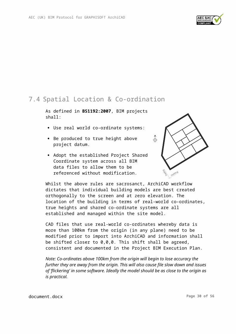
As defined in BS1192:2007, BIM projects shall:
Use real world co-ordinate systems:
Be produced to true height above project datum.
Adopt the established Project Shared Coordinate system across all BIM data files to allow them to be referenced without modification.
Whilst the above rules are sacrosanct, ArchiCAD workflow dictates that individual building models are best created orthogonally to the screen and at zero elevation. The location of the building in terms of real-world co-ordinates, true heights and shared co-ordinate systems are all established and managed within the site model.
CAD files that use real-world co-ordinates whereby data is more than 100km from the origin (in any plane) need to be modified prior to import into ArchiCAD and information shall be shifted closer to 0,0,0. This shift shall be agreed, consistent and documented in the Project BIM Execution Plan.
Note: Co-ordinates above 100km from the origin will begin to lose accuracy the further they are away from the origin. This will also cause file slow down and issues of ‘flickering’ in some software. Ideally the model should be as close to the origin as is practical.
Real-world co-ordinates are then re-established in the ArchiCAD environment and site / true locations are managed within.
Data exported from ArchiCAD can then be either real-world or local and whilst the majority of data will need to be delivered in OS co-ordinates for the purposes of collaboration and cross-referencing, some software (e.g. certain structural analysis software) requires data to be located at 0,0. For export to such software, local coordinate systems must be utilised.
Model exchange should always be from real-world co-ordinates and therefore should always be exported from the site model rather than the building model.
document.docx Page 25 of 45

AEC (UK) BIM Protocol for GRAPHISOFT ArchiCAD
7.4.1 Large sites (Local Scale Factor)
For large sites there is a potential for the curvature of the earth to play a factor in terms of the site setting out. In particular, while Ordnance Survey National Grid coordinates are based on a ‘flat earth’ projection, actual measurements on site are typically based on a ‘round earth’, which can lead to significant setting out discrepancies when projected over long distances.
It is typically beneficial for all sites to be set out based on a ‘flat earth’ model in order to be able to tie into the Local Project Grid derived from the Ordnance Survey National Grid and more easily reference in important features surrounding the site (e.g. utilities connections etc).
In order to resolve the potential round earth / flat earth discrepancies an Ordnance Survey Projection or Local Scale Factor (LSF) must be applied. The LSF varies according to location across the UK, but often (i.e. typically for individual sites, as opposed to regional studies) a uniform site specific LSF can be applied without introducing significant errors. This LSF should be obtained / calculated as early as possible to ensure a uniform topographic base is being used across the entire project.
Assuming a ‘flat earth’ basis; all design models, drawings and associated setting out information should be based upon the Local Project Grid derived from the Ordnance Survey National Grid coordinates, (standard northings/eastings etc). Site setting out for construction activities will typically need to incorporate ‘control stations’ at regular intervals to ensure that round earth / flat earth discrepancies are ‘smoothed out’ over the length and breadth of the site. (If possible this should be agreed in principle with the site setting out team prior to commencement of design activities.)
All site topographic surveys should be commissioned such that the output has been converted to OS National Grid using the site specific LSF prior to use for design purposes.
document.docx Page 26 of 45
AEC (UK) BIM Protocol for GRAPHISOFT ArchiCAD
7.5 Units and Measurement
See main AEC (UK) BIM Protocol for recommendations regarding units and measurement.
ArchiCAD users have control over Working Units and Dimension Units separately from the Options > Project Preferences Menu. A set of Dimension Unit options can be set and saved with a name for selection under the View definition settings. These should be set up in line with the recommendations made in the AEC (UK) BIM Protocol. The following is a recommended format for Project Preference naming -
Field 1: Number
A sequential number with 2 digits. (01, 02, 03 etc)
Field 2: ProjectPreference (Optional)
Adding this field aids navigation, particularly in Quick Options palette.
Field 3: Description
Description of Project Preference and should be in CamelCase.
Example: 01-ProjectPref-Standard
All fields should be separated by hyphen.
The options for Calculation Units & Rules, Zones, Construction Elements and Reference Levels should be setup under the Project Preferences and will be specific to that project. They therefore need to be set in the Office or Project Specific template file (.tpl).
Units and Measurement should be setup within the companies Office Template and not deviated from without prior agreement from the person responsible.
document.docx Page 27 of 45
1Number
2ProjectPreference
3Description

AEC (UK) BIM Protocol for GRAPHISOFT ArchiCAD
8 Folder Structure and Naming Conventions
8.1 Introduction
8.2 Project Folder Structure
8.2.1 Central Resource
Standard templates, Central BIM Resource Libraries, Attribute files, Translators, Favourites, Schedules, Work Environment Profiles etc and other non-project specific data shall be held within a central location, with restricted write access.
Central resources shall be organised by software and version. A central resource will be stored centrally for access by all appropriate staff. This may be a server, intranet, extranet etc. depending on company systems and access requirements.
Copies of Central BIM Resource Libraries (typically saved as container files – LCF) must be stored on each server and users must only connect to the library on the same server as the project.
8.2.2 Local Project Folder Structure
Generally files should not be stored on local machines. The only exceptions are when files are copied purely for viewing purposes or a Teamwork Travel Pack has been generated to allow a user to work offline whilst out of the office.
8.3 General Naming Conventions
8.4 Model File Naming
document.docx Page 28 of 45

AEC (UK) BIM Protocol for GRAPHISOFT ArchiCAD
8.5 Division Naming
ArchiCAD is managed using a combination of Layers (with associated Layer Combinations) and Renovation Status to manage division of information.
8.5.1 Layers
ArchiCAD uses Layers to manage both data within the modelling environment and also for control of output CAD and BIM data. It is recommended that the layering system is in accordance with the recommendations made in the AEC (UK) Protocols.
Layers are used for both managing CAD and BIM data and so it needs to be understood that some other software will be able to view and use layers as a way of filtering information.
The person responsible should establish a base set of Layers suitable for the type and scale of work and include these within an Office Template.
It is recommended that Layers are documented outside ArchiCAD for both ArchiCAD users and for others who wish to utilise the layers. This document should be included as an Appendix to the Project BIM Execution Plan.
Layers additional to the Office Template that have been added by the project team should also be documented in the Project BIM Execution Plan.
document.docx Page 29 of 45
AEC (UK) BIM Protocol for GRAPHISOFT ArchiCAD
8.5.2 Layer management
Layers within GRAPHISOFT ArchiCAD can be managed using Layer Combinations. The person responsible should setup standard Layer Combinations within the Office Template.
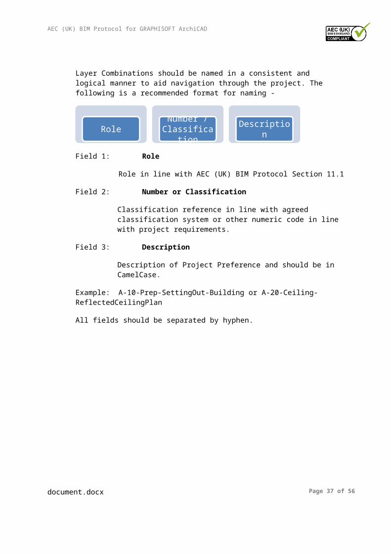
Layer Combinations should be named in a consistent and logical manner to aid navigation through the project. The following is a recommended format for naming -
Field 1: Role
Role in line with AEC (UK) BIM Protocol Section 11.1
Field 2: Number or Classification
Classification reference in line with agreed classification system or other numeric code in line with project requirements.
Field 3: Description
Description of Project Preference and should be in CamelCase.
Example: A-10-Prep-SettingOut-Building or A-20-Ceiling-ReflectedCeilingPlan
All fields should be separated by hyphen.
document.docx Page 30 of 45
1Role 2Number / Classification
3Description

AEC (UK) BIM Protocol for GRAPHISOFT ArchiCAD
8.5.3 Renovation filters and renovation display
Elements can be set to an Existing, Demolished or New status. Elements can then be filtered depending on what needs to be displayed for different views of the model. This is done with Renovation Filters.
Renovation Filters should be named and setup in a consistent and logical manner to aid navigation through the project. The following is a recommended format for naming -
Field 1: Number
A sequential number with 2 digits. (01, 02, 03 etc)
Field 2: Renovation (Optional)
Adding this field aids navigation, particularly in Quick Options palette.
Field 3: Description
Description of Renovation filter and should be in CamelCase.
Example: 01-Renovation-Existing
All fields should be separated by hyphen.
8.6 Library Object Naming
It is recommended that the standard ArchiCAD library maintain the original naming as shipped with the product. Any vendor-supplied object which is altered in any way by the user is to be treated as a new element and named / stored accordingly in either the Central BIM Resource Library or Project BIM Resource Library.
Objects imported from external sources, or internal objects copied to create a project-specific library shall use a consistent naming convention in line with the recommendations made in the AEC (UK) BIM Protocol or as agreed in the Project BIM Execution Plan.
Where Library Objects are added to a Project they may by default be added to the ‘Embedded Library’. While this may be satisfactory for an Unshared project it is not suitable for a Teamwork Project or one with many Hotlinks. In such cases an external Project Library or BIM Server Library (as appropriate) needs to be established and objects should be removed from the Embedded Library to this.
document.docx Page 31 of 45
1Number 2Renovation 3Description

AEC (UK) BIM Protocol for GRAPHISOFT ArchiCAD
For ArchiCAD users, the Type and Grade / Level of detail should be considered optional.
8.7 Object Property Naming
GRAPHISOFT ArchiCAD contains standard IFC Property Sets. These Property Sets allow the user to complete standard fields in line with the IFC standard. Each type of element within a model will contain different data depending on how the element has been classified in the Element Classification field.
Whilst the standard IFC Property Sets are built-in to the software, ArchiCAD also allows companies and individuals to add additional Property Sets based on their needs. Data can either be added at a project level or an element level.
Project level IFC can be added at File > File Special > IFC2x3 > IFC Scheme Setup
Additional Property Sets should be added at the appropriate level. The person responsible should consider the companies standard data needs and add these to the Office Template.
The naming of any new Property Set and property set data should avoid conflict with the standard Property Sets and therefore should be named in the following format:
Field 1: Creator Identifier
This a unique identifier for the creator of the Property Set. So for example a company called Joe Bloggs Architects might use JBA
Field 2: Property Set
Should state Pset.
Field 3: Description
Description of Property Set and should be in CamelCase.
Example: JBA_Pset_General
All fields should be separated by Underscore.
Individual data for each Property Set should be added as CamelCase and care should be taken to ensure spelling is correct.
document.docx Page 32 of 45
1Creator Identifier
2Property Set 3Description

AEC (UK) BIM Protocol for GRAPHISOFT ArchiCAD
8.8 View Naming
Views should be named in a consistent and logical manner to aid navigation through the project. Views should be assembled in folders, which should also be organised and named in a consistent and logical manner to aid navigation through the project
Different approaches to View naming have been utilized but organizations should be consistent in their approach. The following is an example of how Views might be handled:
Field 1: Zone
This is the code from the Project Map where coding has been used to identify elements in the model. For example, Level 01 would be L01.
Field 2: Classification (Optional)
Classification reference in line with agreed classification system.
Classification is not required for cloned Views.
Field 3: Description
Description of View name
Example: D01-2550 Window Details
Fields 1 and 2 should be separated by hyphen.
Note: Cloned Views automatically take the name of the View that they have been created from. These cannot be amended and therefore may not follow the naming convention.
document.docx Page 33 of 45
1Zone 2Classification 3Description

AEC (UK) BIM Protocol for GRAPHISOFT ArchiCAD
8.9 View List Scheduling
Not applicable to GRAPHISOFT ArchiCAD.
8.10 Data Organisation
8.11 Sheet Naming
document.docx Page 34 of 45

AEC (UK) BIM Protocol for GRAPHISOFT ArchiCAD
9 Presentation Styles9.1 Introduction
This section defines the criteria which ensure the plotted appearance of drawing output from the BIM is consistent and of the highest quality.
9.2 AEC (UK) Compliant Materials
To be developed in due course.
9.3 Annotation
9.4 Text Assignment
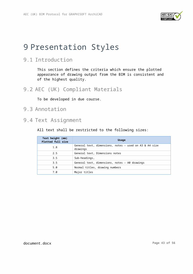
All text shall be restricted to the following sizes:
Text height (mm) Plotted full size Usage
1.8 General text, dimensions, notes – used on A3 & A4 size drawings
2.5 General text, Dimensions notes
3.5 Sub-headings,
3.5 General text, dimensions, notes – A0 drawings
5.0 Normal titles, drawing numbers
7.0 Major titles
document.docx Page 35 of 45

AEC (UK) BIM Protocol for GRAPHISOFT ArchiCAD
9.5 Line Weights
Line weights or Pen weights as they are more commonly known within ArchiCAD can control the graphical display of on-screen data as well as all published output.
The plotted/printed appearance of modelled components shall be:
Consistent across the project
Represented in a manner that provides ‘depth’ to the final published output and allows for adequate differentiation of elements cut in section, profile view and priority elements
Pen weights on published information are controlled within ArchiCAD by a combination of the Pen number selected and the chosen Penset.
The following is a recommended format for naming of Pensets -
Field 1: Number
A sequential number with 2 digits. (01, 02, 03 etc)
Field 2: Penset (Optional)
Adding this field aids navigation, particularly in Quick Options palette.
Field 3: Description
Description of Penset and should be in CamelCase.
Example: 01-Penset-Model
All fields should be separated by hyphen.
There are 255 pens within ArchiCAD.
Generally it is recommended that pen weights are restricted to the following where possible – 0.13, 0.18, 0.25, 0.35, 0.50, 0.70, 1.00, 1.40 and 2.00mm. These are in line with ISO 128.
document.docx Page 36 of 45
1Number 2Penset 3Description
AEC (UK) BIM Protocol for GRAPHISOFT ArchiCAD
9.6 Line Patterns
In GRAPHISOFT ArchiCAD, Line Patterns are referred to as Line Types.
Line Types are used for all draughting production work. It is recommended that the Line Types provided with the standard ArchiCAD template are maintained. Additional Line Types required should be added after the final line type attribute in the template file. These can be added into an office template or added to project specific files as required.
9.7 Line Styles
See 9.6 Line Patterns.
9.8 Hatching and Filled Regions
Default Fill Patterns for Model and Draughting, which are loaded into the default templates, should be used.
Alternative Fill Patterns shall be used only with the approval of the person responsible.
Fills shall be created using the relevant tools available within the software.
Where possible, hatch patterns should be assigned to the relevant materials for the elements, rather than assigned as 2D patches.
Care shall be taken to ensure that the draw order and transparency settings of filled regions are appropriate to the situation so as not to cover required graphical information.
Note: Cut fill patterns within ArchiCAD form the exported IFC material and therefore care should be taken to ensure the cut fill chosen reflects the material of the element it is cutting through.
9.9 View Templates
See 7.3 Drawing Compilation.
9.10 Dimensioning
See the generic AEC (UK) BIM Protocol.
It should also be noted that elements that may be replaced later in the process should not be dimensioned to. For example, a structural frame produced by the architect will be replaced by a Structural Engineer’s frame and subsequently by a Fabricators model. Dimensions should therefore be to a reference point rather than the element itself.
document.docx Page 37 of 45

AEC (UK) BIM Protocol for GRAPHISOFT ArchiCAD
Also great care should be taken to ensure that the correct Partial Structure Display is set before utilizing dimensions.
9.11 Drawing Borders and Title Blocks
Corporate titleblocks should be setup within the Office Template(s) on Master Layouts. Layouts should be created for each standard paper size (e.g. A4, A3, A2, A1 and A0).
Examples of drawing sheet templates are contained in Appendix E of ‘A Standard Framework and Guide to BS1192’.
In ArchiCAD, information on title blocks can be automated to update fields on multiple sheets. Careful consideration should be given to what can be fully automated. Information that can be automated should then be set as Autotext on the Master Layout sheet(s).
To aid the user it is recommended that the office template has as many fields completed as possible and that ‘dummy’ text is inserted in other fields the user is required to complete. E.g. Against Project Name it has in the required field Project Name. The user should then amend the fields in the Project Info dialogue box (available under File > Info > Project Info) as required.
Project-specific title blocks shall be created by amending the Office Template and saved as a Project Specific Template(s) within the project folder structure (see Appendix 11.2).
9.12 Symbology
Standard symbols such as north points, dimension bars, etc. are stored within the appropriate BIM Resource Libraries.
North points should be included on all building and site plan information.
9.13 Copyright
document.docx Page 38 of 45
AEC (UK) BIM Protocol for GRAPHISOFT ArchiCAD
10 Resources10.1 Introduction
10.2 Software
10.3 BIM Content / Resource Libraries
BIM Resource Libraries hold objects, textures and other data for use within CAD and BIM files. They may also hold macros, textures and user interfaces which are utilised by some BIM objects. These are generally not used directly by the user and care should be taken to ensure relevant supporting information is contained within the correct library.
Although ArchiCAD supports the use of embedded libraries, these are not recommended for large or Teamwork projects and all content should be stored within with a Central BIM Resource Library or a Project BIM Resource Library as appropriate.
Note: The only exception to this rule is for Property Objects on Teamwork projects, which are best embedded.
Central BIM Resource Libraries can get very large and it is recommended to break them into sub-folders so that only those types of objects required for a particular project are loaded and not the whole library.
See also the generic AEC (UK) BIM Protocol.
10.3.1 Custom ArchiCAD Objects
Any created / downloaded ArchiCAD GDL objects should all have preview images.
ArchiCAD objects should also ensure that the correct Subtype is selected before incorporation into the Central BIM Resource Library or Project BIM Resource Library. Note: This is particularly important when it comes to IFC export.
10.3.2 ArchiCAD Library
Each version of ArchiCAD is provided with a standard library for use with that specific version. All project files should have the ArchiCAD library loaded by default. When a project moves from one version of ArchiCAD to another it is advisable to ensure that the Library for the current version is loaded plus the appropriate ‘Migration Libraries’ back to the file’s original version.
document.docx Page 39 of 45

AEC (UK) BIM Protocol for GRAPHISOFT ArchiCAD
10.3.3 Central BIM Resource Library
Content shall be segregated by software product and version.
When content is updated for use in newer product version:
The original data shall be maintained,
The updated version of the content shall be created in the appropriate location for that product & version. This avoids ‘forwards incompatibility’ when using content with the version of the software for which it was originally created.
10.3.4 Project BIM Resource Library
This shall be the repository for the storage of project specific content where additional content is required due to project or client requirements.
Objects, textures and other data produced in the process of completing the project shall be held within the Project BIM Resource Library (refer to Appendix 11.2).
The Project BIM Resource Library may be held within the project folder structure or on larger projects, on a BIM Server. On Teamwork projects this Library must be uploaded to the BIM Server as a BIM Server Library. If this Library was loaded when the project was shared, the appropriate BIM Server Library will be created automatically.
On a Teamwork project, any new Library objects must be added to the Project BIM Resource Library. This must then be used as the source to refresh the appropriate BIM Server Library.
Libraries should be clearly named to make it clear which project they are attached to.
No more than one project specific library should be attached to each project, except where more than one project is combined into a wider site or central model.
document.docx Page 40 of 45

AEC (UK) BIM Protocol for GRAPHISOFT ArchiCAD
10.4 Meta-data
Meta data within ArchiCAD can either come from object parameters or from IFC data. Generally speaking it is recommended that IFC data fields be used where possible, although object parameter data can be linked to IFC data fields as required to allow the user to input into object parameter fields.
Careful consideration should be made to what data is required at the appropriate stages in projects.
10.4.1 Favorites
ArchiCAD allows the user to configure elements and objects with specific settings. This allows company standards to be developed within the Office Template. For objects these can be configured for geometry, 2D/3D display, layer allocation, and data requirements and for elements for 2D/3D display, layer allocation and data requirements.
Favorites are considered an integral part of data delivery for BIM projects using ArchiCAD. Creating them allows the development and control of company standards and greatly enhances productivity.
Users should also be encouraged to utilise Favorites wherever possible.
10.4.2 ArchiCAD object parameters
ArchiCAD allows users to input data directly into objects as part of the object settings. There are two ways to export this meta-data. This can either be done by linking the object data to IFC parameters or it can be done by choosing the required data to export.
10.4.3 IFC data
ArchiCAD comes with many in-built IFC ‘Property Sets’. These are developed along standards documented by buildingSMART. (The technical website can be found here - http://buildingsmart-tech.org/ifc/IFC2x3/TC1/html/index.htm).
As a minimum for successful exchange of geometry (and of course data) particular importance is placed on ensuring that the Element Classification is correctly assigned. It should also be noted that some Element Classifications also have ‘Predefined Types’. So for example a ‘floor finish’ would be classified by a user as a Covering (IfcCovering) but they would then also need to select a predefined type of FLOORING from the menu.
Particular care should be given to elements that are modelled with a tool that is not specifically designed for its original purpose. For example, ArchiCAD’s slab tool can be used for slabs (floors) but also for ceilings, raised access floors and floor finishes. Users should ensure the Element Classifications are defined correctly.
document.docx Page 41 of 45

AEC (UK) BIM Protocol for GRAPHISOFT ArchiCAD
It should be noted that the user is not expected to complete every standard field but companies should determine their standard company requirements. Project requirements may then deviate where necessary and this should be documented in the Project BIM Execution Plan.
10.4.4 COBie data
GRAPHISOFT have produced a guidance document regarding COBie data input into ArchiCAD. This is available at http://www.graphisoft.com/support/ifc/downloads/. Locations for where this data is entered into ArchiCAD is contained within the GRAPHISOFT documentation.
In order to assist in COBie delivery it is recommended that the following Contact data is input into the Office Template.
- Category- Company- Phone- Street- PostalBox- Town- StateRegion- PostalCode- Country
This reduces the need for repeated entry of data and ensures consistency across projects.
Project Templates should add the following Contact data when a project template is created.
- Email- GivenName- FamilyName
If known, it is also recommended to insert the following Facility data to the Project Template.
- Name- Category- ProjectName- SiteName- Description- ProjectDescription- SiteDescription- Phase
Again if known, the following Floor data to the Project Template.
document.docx Page 42 of 45
AEC (UK) BIM Protocol for GRAPHISOFT ArchiCAD
- Name- Category- Description
10.5 Keyboard Shortcuts
Generally users should endeavour to use the keyboard shortcuts provided with the standard ArchiCAD template.
However, ArchiCAD does allow users to have shortcuts and other user specific settings. These settings are controlled within the Work Environment Profile (WEP).
The Work Environment Profile is available under the ArchiCAD or Options menu bars. Users may setup User Preference Schemes, Shortcut Schemes, Tool Schemes, Palette Schemes and Command Layout Schemes. Users however should not deviate from agreed office Company Standard Scheme.
Where a user chooses to setup their own WEP they should store each profile option with an appropriate name. For example, if Joe Bloggs wanted to have his own Shortcut Scheme he should save this as Joe Bloggs SS16 (where 16 is the version). Once each setting has been saved the user should then set up a WEP with the required Profile Options. This should then be named appropriately e.g. Joe Bloggs WEP 16.
Once the WEP is created this should then be exported and stored centrally on a server for use with other projects or on other machines as required.
It is recommended that users setup WEP’s for each version and do not import previous WEPs as this can lead to some functionality being lost.
11 Appendices11.1 Model File Naming Codes
document.docx Page 43 of 45

AEC (UK) BIM Protocol for GRAPHISOFT ArchiCAD
11.2 Project Folder Structure
The following folder structure is provided as an example arrangement, designed to encourage compliancy with the strategies contained within this protocol.
This is provided as an example only and should not be used in preference to or replace any internal company quality assured standard folder structures. Always consider your company processes and procedures, especially if ISO accreditation is involved before adopting change.
- [Project Folder] - BIM [BIM data repository]
- 01-WIP [WIP data repository]
- CAD-BIM [CAD, BIM and layout files (incl. ‘Modified’)]- Export [Export data e.g. gbXML or images]- WIP_TSA [WIP Temporary Shared Area (TSA)]
- 02-Shared [Verified Shared data]
- CAD [CAD data/output files]- BIM [Design models]- CoordModels [Compilation models]
- 03-Published [Published Data]
+ YYYYMMDD-Description [Sample submission folder]+ YYYYMMDD-Description [Sample submission folder]
- 04-Archived [Archived Data repository]
+ YYMMDD-Description [Archive folder]+ YYMMDD-Description [Archive folder]
- 05-Incoming [Incoming Data repository]
- Source [Data originator]+ YYYYMMDD-Description [Incoming folder]
+ Source [Data originator]
- 06-Resource [Project BIM Resources Library]
+ Logos [Project logos]+ ProjectBIMResourceLibrary [Project specific BIM content]+ ProjectTemplates [Project specific templates]+ Standards [Project standards]+ Translators [Project translators for DWG, IFC etc]
document.docx Page 44 of 45

AEC (UK) BIM Protocol for GRAPHISOFT ArchiCAD
No spaces or special characters are to be used in the folder naming as this can potentially interfere with certain file management tools and collaboration across the internet.
document.docx Page 45 of 45