· web viewwe xor t with the 4-byte word n bytes before in the expandedkey (where n is once 16...
TRANSCRIPT
www.final-yearproject.com | www.finalyearthesis.com
In today’s world most of the communication is done using electronic media.
Data Security plays a vital role in such communication. Hence, there is a need to
protect data from malicious attacks. Cryptography is the science of secret codes,
enabling the confidentiality of communication through an insecure channel. It protects
against unauthorized parties by preventing unauthorized alteration of use. Generally
speaking, it uses a cryptographic system to transform a plaintext into a cipher text,
using most of the time a key.
Advanced Encryption Standard (AES), also known as Rijndael, is an
encryption standard used for securing information. AES was published by NIST
(National Institute of Standards and Technology). AES is a block cipher algorithm
that has been analyzed extensively and is now used widely. AES is a symmetric block
cipher that is intended to replace DES as the approved standard for a wide range of
applications. The block cipher Rijnddael was designed by Dr. Joan Daemen and Dr.
Vincent Rijmen and the name of the algorithm is a combination of the names of its
two creators. Rijndael is very secure and has no known weakness. Rijndael is
conventional (symmetric key) system and is relatively simple cipher in many respects.
It takes an input block of a certain size, usually 128, and produces a corresponding
output block of the same size. The transformation requires a second input, which is
the secret key. It is important to know that the secret key.
In this work, both encryption and decryption will be carried out with the key
length of 128 bits, that is, both AES encrypter and the AES decrypter were integrated.
Hence the input block and secret key will be provided for encryption and the cipher
block and same secret key will be provided to the decryption to get the proper block
as output. All the transformations of both Encryption and Decryption will be
developed using VHDL language and will be verified with the help of its simulation
result.
The AES Encryption and Decryption is synthesized on FPGA family of
Virtex-2 using Xilinx ISE tool and hence the design operates at a maximum clock
frequency of 18.970 MHz with a minimum period of 52.716ns.
1
www.final-yearproject.com | www.finalyearthesis.com
INDEX
1.INTRODUCTION 1-13
1.1 Introduction 1
1.1.1 What is cryptography 1
1.1.2 How does cryptography work 2
1.1.3 The purpose of cryptography 3
1.2 Methods of encryption 4
1.2.1 Symmetric cryptography 4
1.2.2 Asymmetric cryptography 7
1.3 Types of cryptographic algorithms 10
1.4 Introduction to AES 11
1.4.1 Block cipher 12
1.5 Application 13
2. ADVANCED ENCRYPTION STANDARD ALGORITHM 14-31
2.1 Introduction 14
2.2 Terminologies 14
2.3 Algorithm parameters 15
2.4 AES algorithm 16
2.4.1 Specification 16
2.4.2 Description 16
2.5 Encryption 18
2.5.1 AES cipher functions 19
2.5.1.1 Subbytes transformation
2.5.1.2 Shiftrows transformation 21
2.5.1.3 Mixcolumns transformation 22
2.5.1.4 Addroundkey transformation 24
2.5.2 Key expansion 25
2.6 Decryption
28
2.6.1 AES inverse cipher functions 29
2.6.1.1 Invsubbytes transformation 29
2
www.final-yearproject.com | www.finalyearthesis.com
2.6.1.2 Invshiftrows transformation 29
2.6.1.3 Invmixcolumns transformation 30
2.7 Summary 31
3. AES ALGORITHM IMPLEMENTATION 32-40
3.1 Introduction 32
3.2 Implementation requirements 32
3.3 Notation and conventions 33
3.4 Mathematical preliminaries 35
3.5 General implementation flow 36
3.6 Implementation 37
3.7 Summary 40
4.CODING 41-61
4.1 Package of functions required for AES algorithm 41
4.2 Entity for AES encryption / decryption round 51
4.3 Entity for last AES encryption / decryption round 53
4.4 Entity for testing AES encryption / decryption round 54
4.5 Entity for testing AES encryption / decryption round 59
5.RESULTS AND DISCUSSION 62-75
5.1 Introduction 62
5.2 Simulation results 62
5.3 Introduction to FPGA 71
5.4 Synthesis result 72
5.5 Summary 75
3
www.final-yearproject.com | www.finalyearthesis.com
6.CONCLUSION AND FUTURE SCOPE 76-78
6.1 Conclusion 76
6.2 Future scope 76
7.BIBILOGRAPHY 79
4
www.final-yearproject.com | www.finalyearthesis.com
LIST OF FIGURES
1.1 Encryption and decryption 1
1.2 Using symmetric algorithms, the sender and receiver use the same key
for encryption and decryption functions. 5
1.3 Asymmetric cryptosystem 7
1.4 Type of security service that will be provided 9
1.5 Three types of cryptographic algorithms 11
2.1 Top Level Block Diagram of AES Algorithm 17
2.2 Block Diagram for AES Round and AES Last Round 20
2.3 SubBytes Operation of the State 21
2.4 ShiftRows Operation of the State 22
2.5 MixColumns operates on the State column-by-column 24
2.6 AddRoundKey Operation 25
2.7 InvShiftRows Operation of the State 30
3.1 State Array Input and Output 34
3.2 General Implementation Flow Diagram 36
5.1 Simulation Result of AES Encryption and Decryption for Set-1 Inputs 63
5.2 Simulation Result of AES Encryption and Decryption for Set-2 Inputs 64
5.3 Simulation Result of Encryption with Internal Operation for Set-1 65
5.4 Simulation Result of Decryption with Internal Operation for Set-1 Inputs 67
5.5 Simulation Result of Encryption with Internal Operation for Set-2 Inputs 68
5.6 Simulation Result of Decryption with Internal Operation for Set-2 Inputs 68
5
www.final-yearproject.com | www.finalyearthesis.com
5.7 Simulation Result of Encryption for Set-1 Inputs
69
5.8 Simulation Result of Decryption for Set-1 Inputs 70
5.9 Simulation Result of Encryption for Set-2 Inputs 70
5.10 Simulation Result of Decryption for Set-2 Inputs 71
5.11 Logic Block 72
5.12 RTL Schematic 73
6
www.final-yearproject.com | www.finalyearthesis.com
INTRODUCTIONINTRODUCTION
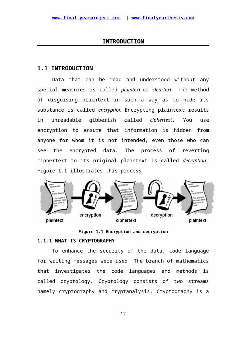
1.1 INTRODUCTIONData that can be read and understood without any special measures is called
plaintext or cleartext. The method of disguising plaintext in such a way as to hide its
substance is called encryption. Encrypting plaintext results in unreadable gibberish
called ciphertext. You use encryption to ensure that information is hidden from
anyone for whom it is not intended, even those who can see the encrypted data. The
process of reverting ciphertext to its original plaintext is called decryption. Figure 1.1
illustrates this process.
Figure 1.1 Encryption and decryption
1.1.1 WHAT IS CRYPTOGRAPHY
To enhance the security of the data, code language for writing messages were
used. The branch of mathematics that investigates the code languages and methods is
called cryptology. Cryptology consists of two streams namely cryptography and
cryptanalysis. Cryptography is a science of coding message secretly while
cryptanalysis is a science of breaking codes.
CRYPTOLOGY
CRYPTOGRAPHY CRYPTANALYSIS
Our project is concerned with cryptography. Cryptography is a science of
using mathematics to encrypt and decrypt data. Cryptography enables to store
7
www.final-yearproject.com | www.finalyearthesis.com
sensitive information or transmit it across insecure networks so that it cannot be read
by any one except the intended recipient.
Cryptography or Cryptology is derived from Greek kryptos “hidden” and the
verb grafo “write” or legein “to speak” is the practice and study of hiding information.
In modern times, Cryptology is considered to be a branch of both mathematics and
computer science, and is afflicted closely with information theory, computer security
and engineering. Cryptography is used in applications present in technology advanced
in societies; examples include the security of the ATM cards, computer pass words
and electronic commerce which all depend upon Cryptography.
Cryptography embraces both cryptography and cryptanalysis. While
cryptography is science of securing data, cryptanalysis is a science of analyzing and
breaking secure communication. Classical involves and interesting combination of
analytical reasoning, application of mathematical tools, pattern finding, determination,
and luck. Cryptanalysts are also attackers.
There are two kinds of cryptography in this world: cryptography that will stop
major governments from reading our files. PGP is also about the latter sort of
cryptography. Cryptography can be strong or weak, as explained above.
Cryptography strength is measured in the time and the resources it would
require to recover plain text. The result of the strong Cryptography is cipher text that
is very difficult to decipher without possession of the appropriate decoding tool. How
difficult? Given all today’s computing power and available time- even a billion
computers doing a billion checks a second – it is not possible to decipher the result of
strong cryptography before the end of the universe.
One would think, then, that strong Cryptography would hold up rather well
against even an extremely determined cryptanalyst. Who’s really to say? No can
prove that the strongest encryption obtainable today will hold up under tomorrow’s
computing power. Vigilance and conservatism will protect us better, however, than
claims of impenetrability.
1.1.2 HOW DOES CRYPTOGRAPHY WORK
A cryptographic algorithm, or cipher, is a mathematical function used in the
encryption and decryption process. A cryptographic algorithm works in combination
with a key—a word, number, or phrase—to encrypt the plaintext. The same plaintext
encrypts to different ciphertext with different keys.
8
www.final-yearproject.com | www.finalyearthesis.com
The security of encrypted data is entirely dependent on two things: the strength of the
cryptographic algorithm and the secrecy of the key.
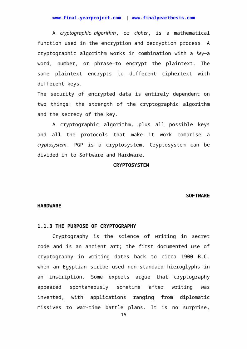
A cryptographic algorithm, plus all possible keys and all the protocols that
make it work comprise a cryptosystem. PGP is a cryptosystem. Cryptosystem can be
divided in to Software and Hardware.
CRYPTOSYSTEM
SOFTWARE HARDWARE
1.1.3 THE PURPOSE OF CRYPTOGRAPHY
Cryptography is the science of writing in secret code and is an ancient art; the
first documented use of cryptography in writing dates back to circa 1900 B.C. when
an Egyptian scribe used non-standard hieroglyphs in an inscription. Some experts
argue that cryptography appeared spontaneously sometime after writing was invented,
with applications ranging from diplomatic missives to war-time battle plans. It is no
surprise, then, that new forms of cryptography came soon after the widespread
development of computer communications.
In data and telecommunications, cryptography is necessary when
communicating over any un-trusted medium, which includes just about any network,
particularly the Internet.
Within the context of any application-to-application communication, there are
some specific security requirements including:
Authentication: The process of proving one's identity. (The primary forms
of host-to-host authentication on the Internet today are name-based or
address-based, both of which are notoriously weak.)
Privacy/confidentiality: Ensuring that no one can read the message except
the intended receiver.
Integrity: Assuring the receiver that the received message has not been
altered in any way from the original.
Non-repudiation: A mechanism to prove that the sender really sent this
message.
9
www.final-yearproject.com | www.finalyearthesis.com
Cryptography, then, not only protects data from theft or alteration, but can also
be used for user authentication. There are, in general, three types of cryptographic
schemes typically used to accomplish these goals: secret key (or symmetric)
cryptography, public-key (or asymmetric) cryptography, and hash functions, each of
which is described below. In all cases, the initial unencrypted data is referred to as
plaintext. It is encrypted into ciphertext, which will in turn (usually) be decrypted into
usable plaintext.
In many of the descriptions below, two communicating parties will be referred
to as Alice and Bob; this is the common nomenclature in the crypto field and
literature to make it easier to identify the communicating parties. If there is a third or
fourth party to the communication, they will be referred to as Carol and Dave.
Mallory is a malicious party, Eve is an eavesdropper, and Trent is a trusted third
party.
1.2 METHODS OF ENCRYPTIONAlthough there can be several pieces to an encryption method, the two main
pieces are the algorithms and the keys. As stated earlier, algorithms are usually
complex mathematical formulas that dictate the rules of how the plaintext will be
turned into cipher text. A key is a string of random bits that will be inserted into the
algorithm. For two entities to be able to communicate via encryption, they must use
the same algorithm and, many times, the same key. In some encryption methods, the
receiver and the sender use the same key and in other encryption methods, they must
use different keys for encryption and decryption purposes. The following sections
explain the difference between these two types of encryption methods.
Symmetric versus Asymmetric Algorithms
Cryptography algorithms use either symmetric keys, also called secret keys, or
asymmetric keys, also called public keys. As encryption was not complicated enough,
the titles that are used to describe the key type’s only make it worse. Just pay close
attention and we will get through this just fine.
1.2.1 SYMMETRIC CRYPTOGRAPHY
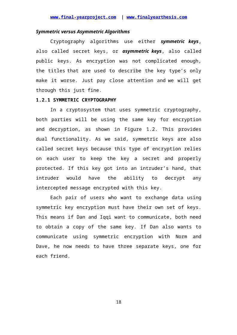
In a cryptosystem that uses symmetric cryptography, both parties will be using
the same key for encryption and decryption, as shown in Figure 1.2. This provides
dual functionality. As we said, symmetric keys are also called secret keys because this 10

www.final-yearproject.com | www.finalyearthesis.com
type of encryption relies on each user to keep the key a secret and properly protected.
If this key got into an intruder’s hand, that intruder would have the ability to decrypt
any intercepted message encrypted with this key.
Each pair of users who want to exchange data using symmetric key encryption
must have their own set of keys. This means if Dan and Iqqi want to communicate,
both need to obtain a copy of the same key. If Dan also wants to communicate using
symmetric encryption with Norm and Dave, he now needs to have three separate
keys, one for each friend.
Figure 1.2 Using symmetric algorithms, the sender and receiver use the same key
for encryption and decryption functions.
This might not sound like a big deal until Dan realizes that he may
communicate with hundreds of people over a period of several months, and keeping
track and using the correct key that corresponds to each specific receiver can become
a very daunting task. If Dan were going to communicate with 10 other people, then he
would need to keep track of 45 different keys. If Dan were going to communicate
with 100 other people, then he would have to maintain and keep up with 4,950
symmetric keys. Dan is a pretty bright guy, but does not necessarily want to spend his
days looking for the right key to be able to communicate with Dave.
The security of the symmetric encryption method is completely dependent on
how well users protect the key. This should raise red flags to you if you have ever had
11
www.final-yearproject.com | www.finalyearthesis.com
to depend on a whole staff of people to keep a secret. If a key is compromised, then
all messages encrypted with that key can be decrypted and read by an intruder.
This is complicated further by how symmetric keys are actually shared and updated
when necessary. If Dan wants to communicate to Norm for the first time, Dan has to
figure out how to get Norm the right key. It is not safe to just send it in an e-mail
message because the key is not protected and it can be easily intercepted and used by
attackers. Dan has to get the key to Norm through an out-of-band method. Dan can
save the key on a floppy disk and walk over to Norm’s desk, send it to him via snail
mail, or have a secure carrier deliver it to Norm. This is a huge hassle, and each
method is very clumsy and insecure. Because both users use the same key to encrypt
and decrypt messages, symmetric cryptosystems can provide confidentiality, but they
cannot provide authentication or non-repudiation. There is no way to prove who
actually sent a message if two people are using the exact same key.
Well, if symmetric cryptosystems have so many problems and flaws, why use
them at all? They are very fast and can be hard to break. Compared to asymmetric
systems, symmetric algorithms scream in speed. They can encrypt and decrypt large
amounts of data that would take an unacceptable amount of time if an asymmetric
algorithm was used instead. It is also very difficult to uncover data that is encrypted
with a symmetric algorithm if a large key size was used.
The following list outlines the strengths and weakness of symmetric key
systems:
Strengths
Much faster than asymmetric systems
Hard to break if using a large key size
Weaknesses
Key distribution It requires a secure mechanism to deliver keys properly. Scalability Each pair of users needs a unique pair of keys, so the number of
Keys grow exponentially.
Limited security It can provide confidentiality, but not authenticity or non-
repudiation.
The following are examples of symmetric key cryptography algorithms:
Data Encryption Standard (DES)
Triple DES (3DES)
12
www.final-yearproject.com | www.finalyearthesis.com
Advanced Encryption Standard (AES)
1.2.2 ASYMMETRIC CRYPTOGRAPHY
Some things you can tell the public, but some things you just want to keep
private.
In symmetric key cryptography, a single secret key is used between entities,
whereas in public key systems, each entity has different keys, or asymmetric keys.
The two different asymmetric keys are mathematically related. If a message is
encrypted by one key, the other key is required to decrypt the message.
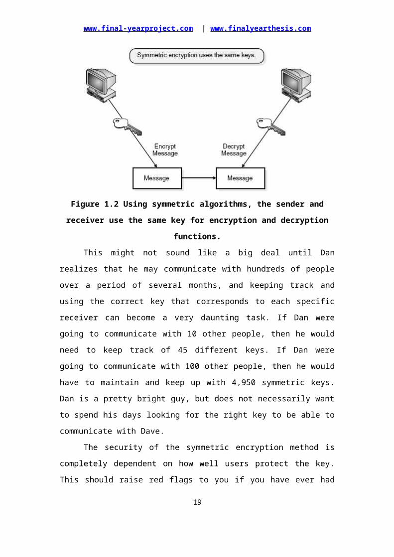
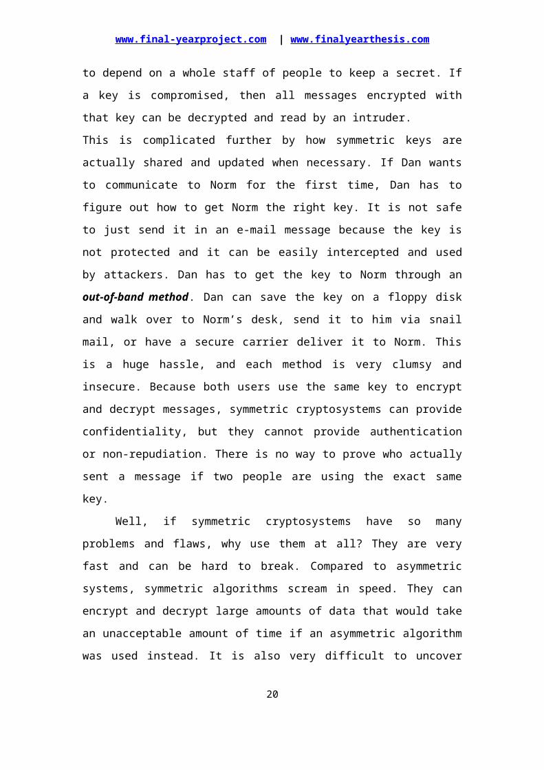
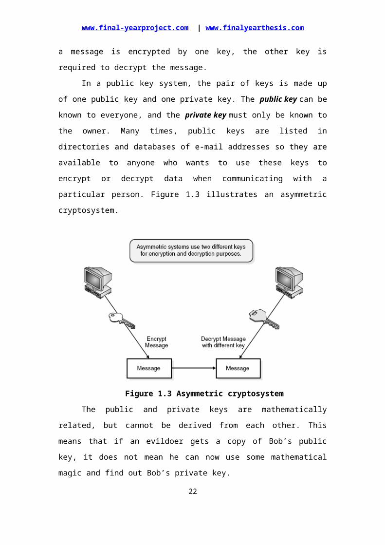
In a public key system, the pair of keys is made up of one public key and one
private key. The public key can be known to everyone, and the private key must only
be known to the owner. Many times, public keys are listed in directories and
databases of e-mail addresses so they are available to anyone who wants to use these
keys to encrypt or decrypt data when communicating with a particular person. Figure
1.3 illustrates an asymmetric cryptosystem.
Figure 1.3 Asymmetric cryptosystem
The public and private keys are mathematically related, but cannot be derived
from each other. This means that if an evildoer gets a copy of Bob’s public key, it
does not mean he can now use some mathematical magic and find out Bob’s private
key.
13
www.final-yearproject.com | www.finalyearthesis.com
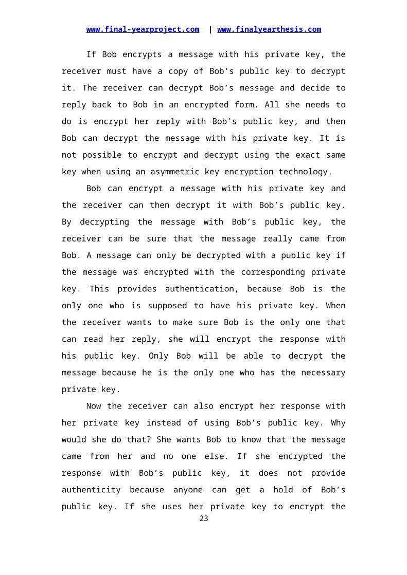
If Bob encrypts a message with his private key, the receiver must have a copy
of Bob’s public key to decrypt it. The receiver can decrypt Bob’s message and decide
to reply back to Bob in an encrypted form. All she needs to do is encrypt her reply
with Bob’s public key, and then Bob can decrypt the message with his private key. It
is not possible to encrypt and decrypt using the exact same key when using an
asymmetric key encryption technology.
Bob can encrypt a message with his private key and the receiver can then
decrypt it with Bob’s public key. By decrypting the message with Bob’s public key,
the receiver can be sure that the message really came from Bob. A message can only
be decrypted with a public key if the message was encrypted with the corresponding
private key. This provides authentication, because Bob is the only one who is
supposed to have his private key. When the receiver wants to make sure Bob is the
only one that can read her reply, she will encrypt the response with his public key.
Only Bob will be able to decrypt the message because he is the only one who has the
necessary private key.
Now the receiver can also encrypt her response with her private key instead of
using Bob’s public key. Why would she do that? She wants Bob to know that the
message came from her and no one else. If she encrypted the response with Bob’s
public key, it does not provide authenticity because anyone can get a hold of Bob’s
public key. If she uses her private key to encrypt the message, then Bob can be sure
that the message came from her and no one else. Symmetric keys do not provide
authenticity because the same key is used on both ends. Using one of the secret keys
does not ensure that the message originated from a specific entity.
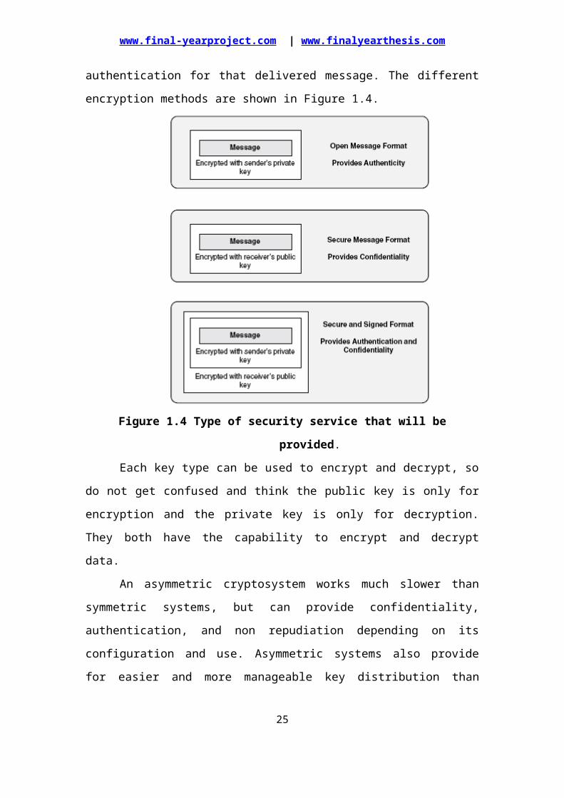
If confidentiality is the most important security service to a sender, she would
encrypt the file with the receiver’s public key. This is called a secure message format
because it can only be decrypted by the person who has the corresponding private
key. If authentication is the most important security service to the sender, then she
would encrypt the message with her private key. This provides assurance to the
receiver that the only person who could have encrypted the message is the individual
who has possession of that private key. If the sender encrypted the message with the
receiver’s public key, authentication is not provided because this public key is
available to anyone.
14
www.final-yearproject.com | www.finalyearthesis.com
Encrypting a message with the sender’s private key is called an open message
format because anyone with a copy of the corresponding public key can decrypt the
message; thus, confidentiality is not ensured.
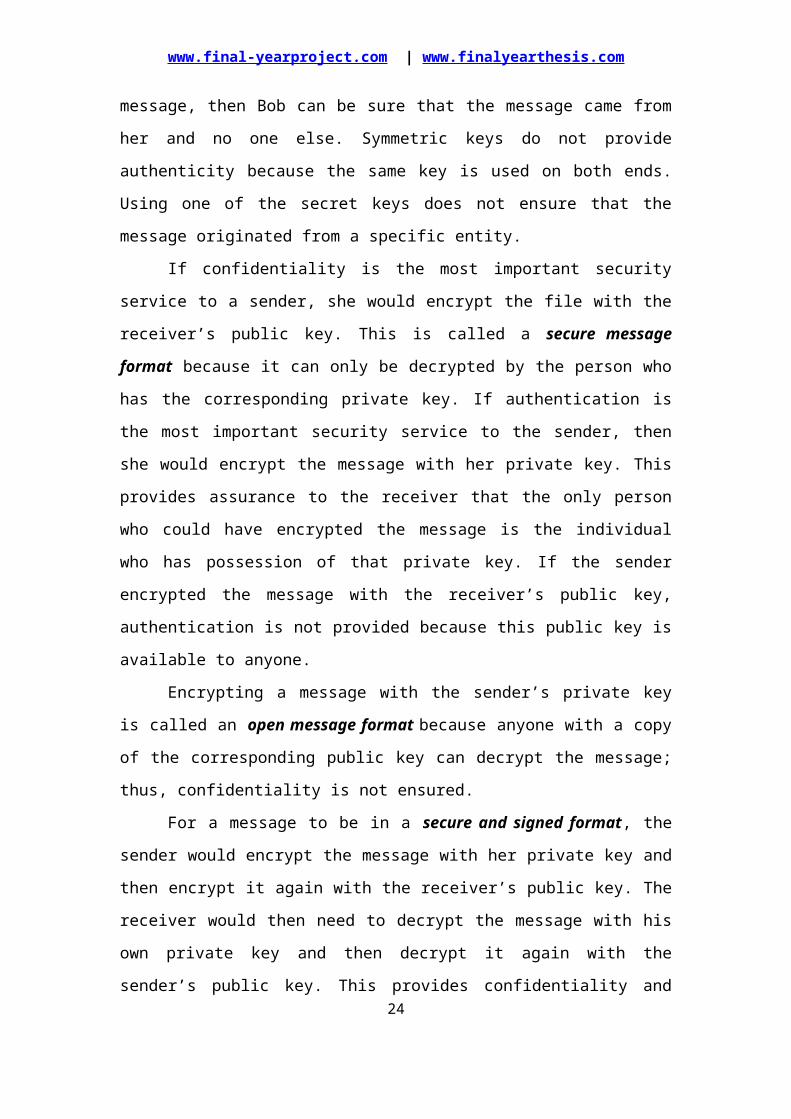
For a message to be in a secure and signed format, the sender would encrypt
the message with her private key and then encrypt it again with the receiver’s public
key. The receiver would then need to decrypt the message with his own private key
and then decrypt it again with the sender’s public key. This provides confidentiality
and authentication for that delivered message. The different encryption methods are
shown in Figure 1.4.
Figure 1.4 Type of security service that will be provided.
Each key type can be used to encrypt and decrypt, so do not get confused and
think the public key is only for encryption and the private key is only for decryption.
They both have the capability to encrypt and decrypt data.
An asymmetric cryptosystem works much slower than symmetric systems, but
can provide confidentiality, authentication, and non repudiation depending on its
configuration and use. Asymmetric systems also provide for easier and more
manageable key distribution than symmetric systems and do not have the scalability
issues of symmetric systems. 15
www.final-yearproject.com | www.finalyearthesis.com
The following outlines the strengths and weaknesses of asymmetric key
systems:
Strengths
Better key distribution than symmetric systems
Better scalability than symmetric systems
Can provide confidentiality, authentication, and non repudiation
Weaknesses
Works much slower than symmetric systems
The following are examples of asymmetric key algorithms:
RSA
Elliptic Curve Cryptosystem (ECC)
Diffie-Hellman
El Gamal
Digital Signature Standard (DSS)
1.3 TYPES OF CRYPTOGRAPHIC ALGORITHMSThere are several ways of classifying cryptographic algorithms. For purposes
of this paper, they will be categorized based on the number of keys that are employed
for encryption and decryption, and further defined by their application and use. The
three types of algorithms those are discussed in Figure 1.5.
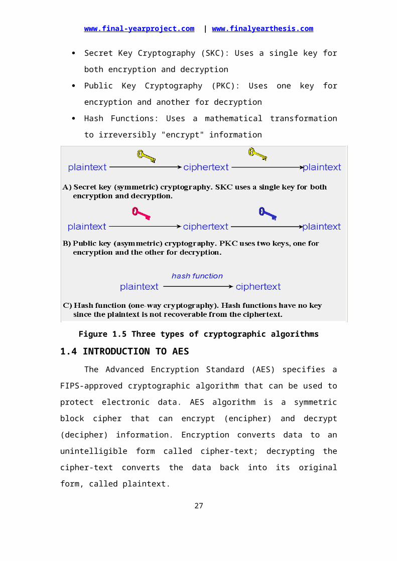
Secret Key Cryptography (SKC): Uses a single key for both encryption and
decryption
Public Key Cryptography (PKC): Uses one key for encryption and another for
decryption
Hash Functions: Uses a mathematical transformation to irreversibly "encrypt"
information
16
www.final-yearproject.com | www.finalyearthesis.com
Figure 1.5 Three types of cryptographic algorithms
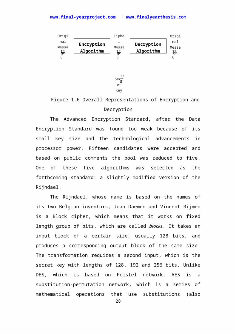
1.4 INTRODUCTION TO AESThe Advanced Encryption Standard (AES) specifies a FIPS-approved
cryptographic algorithm that can be used to protect electronic data. AES algorithm is
a symmetric block cipher that can encrypt (encipher) and decrypt (decipher)
information. Encryption converts data to an unintelligible form called cipher-text;
decrypting the cipher-text converts the data back into its original form, called
plaintext.
Figure 1.6 Overall Representations of Encryption and Decryption
The Advanced Encryption Standard, after the Data Encryption Standard was
found too weak because of its small key size and the technological advancements in
processor power. Fifteen candidates were accepted and based on public comments the
17
Encryption Algorithm
Decryption Algorithm
Original Message
Cipher Message
Original Message
Secret Key
128 128 128
128
www.final-yearproject.com | www.finalyearthesis.com
pool was reduced to five. One of these five algorithms was selected as the
forthcoming standard: a slightly modified version of the Rijndael.
The Rijndael, whose name is based on the names of its two Belgian inventors,
Joan Daemen and Vincent Rijmen is a Block cipher, which means that it works on
fixed length group of bits, which are called blocks. It takes an input block of a certain
size, usually 128 bits, and produces a corresponding output block of the same size.
The transformation requires a second input, which is the secret key with lengths of
128, 192 and 256 bits. Unlike DES, which is based on Feistel network, AES is a
substitution-permutation network, which is a series of mathematical operations that
use substitutions (also called S-Box) and permutations (P-Boxes) and their careful
definition implies that each output bit depends on every input bit.
1.4.1 BLOCK CIPHER
When a block cipher algorithm is used for encryption and decryption
purposes, the message is divided into blocks of bits. These blocks are then put through
substitution, transposition, and other mathematical functions.
The algorithm dictates all the possible functions available to be used on the message,
and it is the key that will determine what order these functions will take place. Strong
algorithms make reengineering or trying to figure out all the functions that took place
on the message, basically impossible.
It has been said that the properties of a cipher should contain confusion and
diffusion. Different unknown key values cause confusion, because the attacker does
not know these values, and diffusion is accomplished by putting the bits within the
plaintext through many different functions so that they are dispersed throughout the
algorithm. Block ciphers use diffusion and confusion in their methods.
Advantages of AES:
Through AES, input message of length 128 bits can be encrypted which is
more than the DES and Triple DES.
AES has the various secret key lengths such as 128 bits, 192 bits and 256 bits,
whereas DES and Triple DES have fixed length of 64 bits.
The cipher key is expanded into a larger key, which is later used for the actual
operation.
The Expanded Key shall ALWAYS be derived from the Cipher Key and never
be specified directly.
18
www.final-yearproject.com | www.finalyearthesis.com
AES is very hard to attack or crack when compared to DES.
AES will be faster when compared to the Triple DES.
1.5 APPLICATION This standard may be used by Federal departments and agencies when an
agency determines that sensitive (unclassified) information (as defined in P. L.
100-235) requires cryptographic protection
High speed ATM/Ethernet/Fiber-Channel switches
Secure video teleconferencing
Routers and Remote Access Servers
In addition, this standard may be adopted and used by non-Federal
Government organizations. Such use is encouraged when it provides the
desired security for commercial and private organizations.
19
www.final-yearproject.com | www.finalyearthesis.com
ADVANCED ENCRYPTION STANDARD ALGORITHM
2.1 INTRODUCTIONThe main objectives of AES are high level security, adoptable to diverse
application, efficient and exportable. In this project work, the plain text of 128 bits is
given as input to encryption block in which encryption of data is made and the cipher
text of 128 bits is throughout as output. The key length of 128 bits is used in process
of encryption. The AES algorithm is a block cipher that uses the same binary key both
to encrypt and decrypt data blocks is called a symmetric key cipher. A commonly
accepted definition of a good symmetric key algorithm, such as the AES, is that there
exists no attack better than key exhaustion to read an encrypted message.
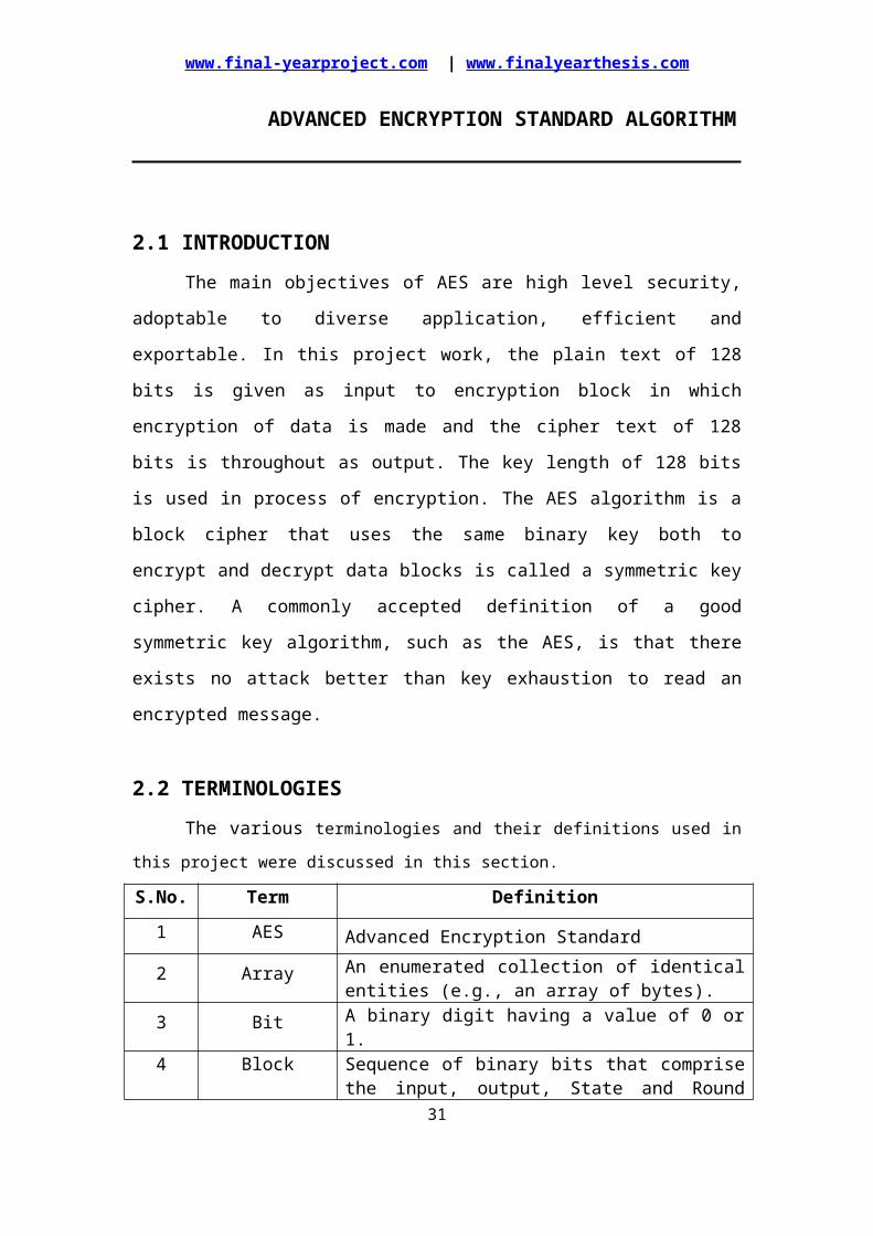
2.2 TERMINOLOGIESThe various terminologies and their definitions used in this project were discussed
in this section.
S.No. Term Definition
1 AES Advanced Encryption Standard
2 Array An enumerated collection of identical entities (e.g., an array of bytes).
3 Bit A binary digit having a value of 0 or 1.
4 BlockSequence of binary bits that comprise the input, output, State and Round Key. The length of a sequence is the number of bits it contains. Blocks are also interpreted as arrays of bytes.
5 Byte A group of eight bits that is treated either as a single entity or as an array of 8 individual bits.
6 Cipher Series of transformations that converts plaintext to cipher text using the Cipher Key.
7 Cipher KeySecret, cryptographic key that is used by the Key Expansion routine to generate a set of Round Keys; can be pictured as a rectangular array of bytes, having four rows and Nk columns.
8 Cipher text Data output from the Cipher or input to the Inverse Cipher.
9 Inverse Cipher Series of transformations that converts cipher text to plaintext using the Cipher Key.
10 Key Expansion Routine used to generate a series of Round Keys from
20

www.final-yearproject.com | www.finalyearthesis.com
the Cipher Key.11 Plaintext Data input to Cipher or output from the Inverse Cipher.
12 Rijndael Cryptographic algorithm specified in this Advanced Encryption Standard (AES).
13 Round KeyRound keys are values derived from the Cipher Key using the Key Expansion routine; they are applied to the State in the Cipher and Inverse Cipher.
14 StateIntermediate Cipher result that can be pictured as a rectangular array of bytes, having four rows and Nb columns.
15 S-boxNon-linear substitution table used in several byte substitution transformations and in the Key Expansion routine to perform a one-for-one substitution of a byte value.
16 Word A group of 32 bits that is treated either as a single entity or as an array of 4 bytes.
Table 2.1 Terminologies and their Definitions
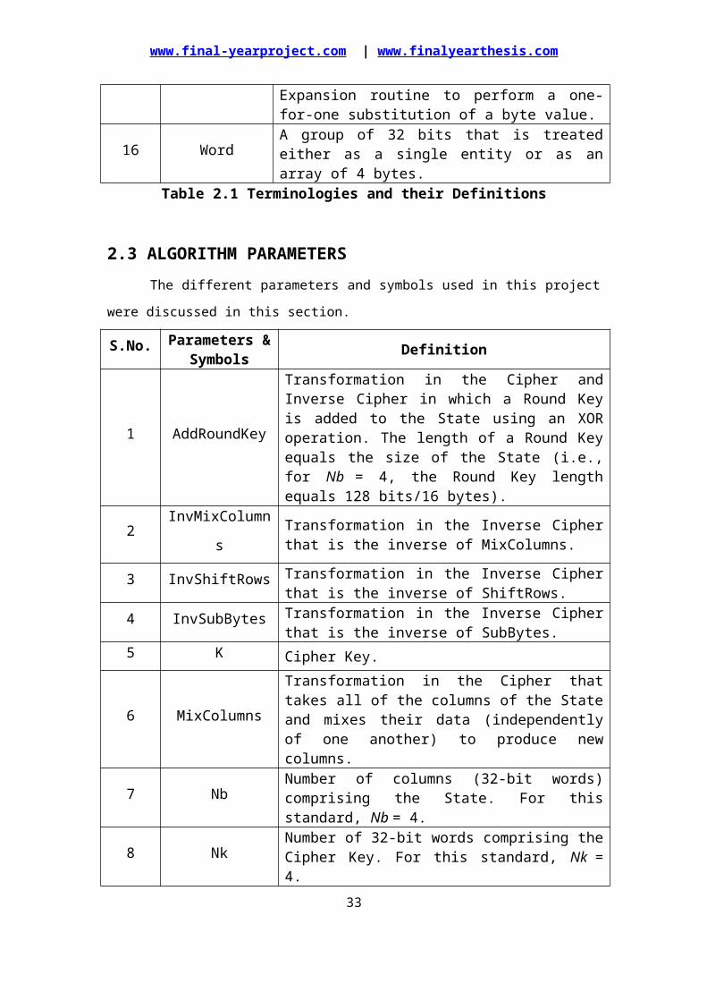
2.3 ALGORITHM PARAMETERSThe different parameters and symbols used in this project were discussed in this
section.
S.No. Parameters & Symbols Definition
1 AddRoundKey
Transformation in the Cipher and Inverse Cipher in which a Round Key is added to the State using an XOR operation. The length of a Round Key equals the size of the State (i.e., for Nb = 4, the Round Key length equals 128 bits/16 bytes).
2 InvMixColumns Transformation in the Inverse Cipher that is the inverse of MixColumns.
3 InvShiftRows Transformation in the Inverse Cipher that is the inverse of ShiftRows.
4 InvSubBytes Transformation in the Inverse Cipher that is the inverse of SubBytes.
5 K Cipher Key.
6 MixColumnsTransformation in the Cipher that takes all of the columns of the State and mixes their data (independently of one another) to produce new columns.
7 Nb Number of columns (32-bit words) comprising the State. For this standard, Nb = 4.
8 Nk Number of 32-bit words comprising the Cipher Key. For this standard, Nk = 4.
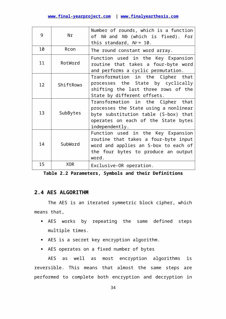
9 Nr Number of rounds, which is a function of Nk and Nb (which is fixed). For this standard, Nr = 10.
21
www.final-yearproject.com | www.finalyearthesis.com
10 Rcon The round constant word array.
11 RotWord Function used in the Key Expansion routine that takes a four-byte word and performs a cyclic permutation.
12 ShiftRowsTransformation in the Cipher that processes the State by cyclically shifting the last three rows of the State by different offsets.
13 SubBytesTransformation in the Cipher that processes the State using a nonlinear byte substitution table (S-box) that operates on each of the State bytes independently.
14 SubWordFunction used in the Key Expansion routine that takes a four-byte input word and applies an S-box to each of the four bytes to produce an output word.
15 XOR Exclusive-OR operation.Table 2.2 Parameters, Symbols and their Definitions
2.4 AES ALGORITHMThe AES is an iterated symmetric block cipher, which means that,
AES works by repeating the same defined steps multiple times.
AES is a secret key encryption algorithm.
AES operates on a fixed number of bytes
AES as well as most encryption algorithms is reversible. This means that
almost the same steps are performed to complete both encryption and decryption in
reverse order. The AES algorithm operates on bytes, which makes it simpler to
implement.
2.4.1 SPECIFICATION
For the AES algorithm, the length of the input block, the output block and
the State is 128 bits. This is represented by Nb = 4, which reflects the number of 32-
bit words (number of columns) in the State. For the AES algorithm, the length of the
Cipher Key, K, is 128 bits. The key length is represented by Nk = 4, which reflects
the number of 32-bit words (number of columns) in the Cipher Key.
For the AES algorithm, the number of rounds to be performed during the
execution of the algorithm is dependent on the key size. The number of rounds is
represented by Nr, where Nr = 10 when Nk = 4.
2.4.2 DESCRIPTION
The AES is an iterated block cipher with a fixed block size of 128 and a
variable key length. The different transformations operate on the intermediate results,
22
www.final-yearproject.com | www.finalyearthesis.com
called state. The state is a rectangular array of bytes and since the block size is 128
bits, which is 16 bytes, the rectangular array is of dimensions 4x4. The basic unit for
processing in the AES algorithm is a byte, a sequence of eight bits treated as a single
entity. The input, output and Cipher Key bit sequences which are processed as arrays
of bytes that are formed by dividing these sequences into groups of eight contiguous
bits to form arrays of bytes.
In the Rijndael version with variable block size, the row size is fixed to four
and the number of columns varies. The number of columns is the block size divided
by 32 and denoted Nb. The cipher key is similarly pictured as a rectangular array with
four rows. The number of columns of the cipher key, denoted Nk, is equal to the key
length divided by 32. AES uses a variable number of rounds, which are fixed: A key
of size 128 has 10 rounds.
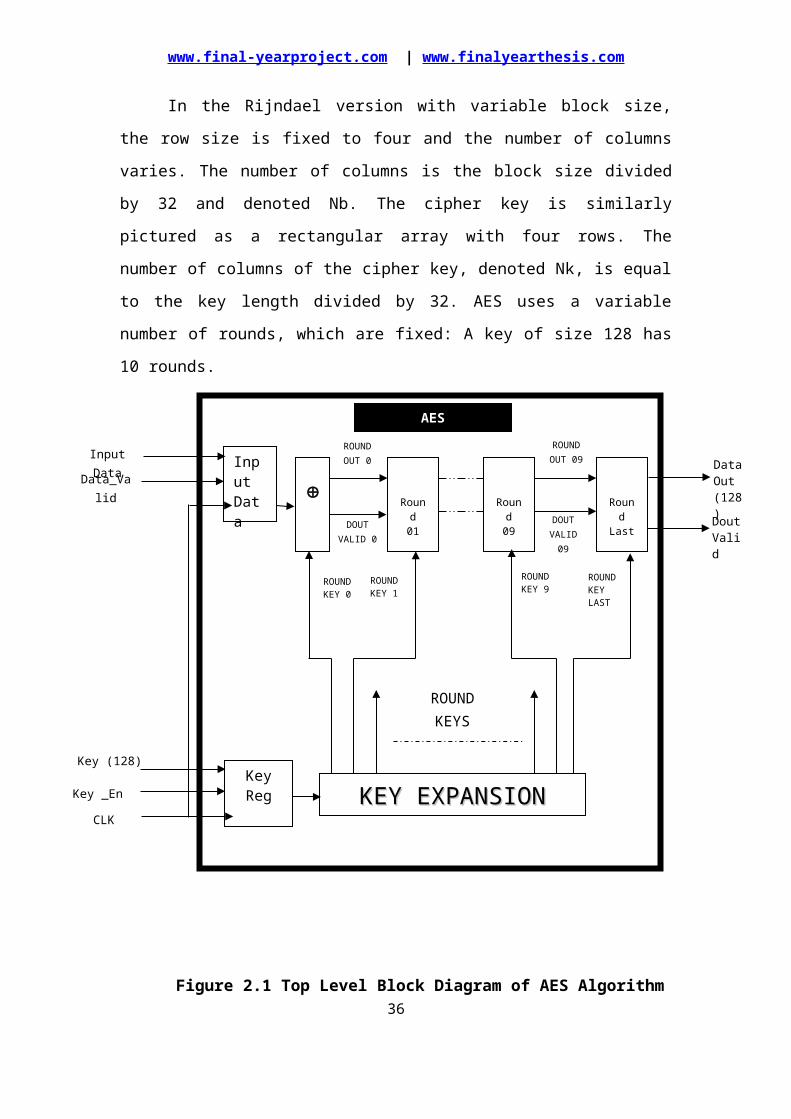
Figure 2.1 Top Level Block Diagram of AES Algorithm
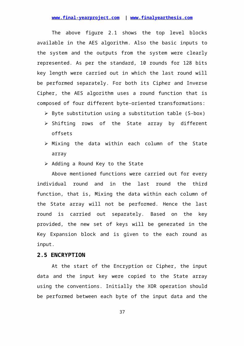
The above figure 2.1 shows the top level blocks available in the AES
algorithm. Also the basic inputs to the system and the outputs from the system were
23
DOUT VALID 0
InputDataData_Valid
Input Data
DOUT VALID 09
CLK
ROUND OUT 0
KEY EXPANSIONKEY EXPANSION
Round01
Round09
RoundLast
ROUND OUT 09
ROUND KEYS
ROUNDKEY 0
ROUNDKEY 1
ROUNDKEY 9
ROUNDKEY LAST
KeyRegKey _En
Key (128)
DataOut(128)
DoutValid
AES
www.final-yearproject.com | www.finalyearthesis.com
clearly represented. As per the standard, 10 rounds for 128 bits key length were
carried out in which the last round will be performed separately. For both its Cipher
and Inverse Cipher, the AES algorithm uses a round function that is composed of four
different byte-oriented transformations:
Byte substitution using a substitution table (S-box)
Shifting rows of the State array by different offsets
Mixing the data within each column of the State array
Adding a Round Key to the State
Above mentioned functions were carried out for every individual round and in
the last round the third function, that is, Mixing the data within each column of the
State array will not be performed. Hence the last round is carried out separately.
Based on the key provided, the new set of keys will be generated in the Key
Expansion block and is given to the each round as input.
2.5 ENCRYPTIONAt the start of the Encryption or Cipher, the input data and the input key were
copied to the State array using the conventions. Initially the XOR operation should be
performed between each byte of the input data and the input key and the output will
be given as the input of the Round-1. After an initial Round Key addition, the State
array is transformed by implementing a round function 10 times, with the final round
differing slightly from the first Nr–1 rounds. The final State is then copied to the
output. The round function is parameterized using a key schedule that consists of a
one-dimensional array of four-byte words derived using the Key Expansion routine.
The individual transformations that carried out are listed below.
SubBytes
ShiftRows
MixColumns
AddRoundKey
24
www.final-yearproject.com | www.finalyearthesis.com
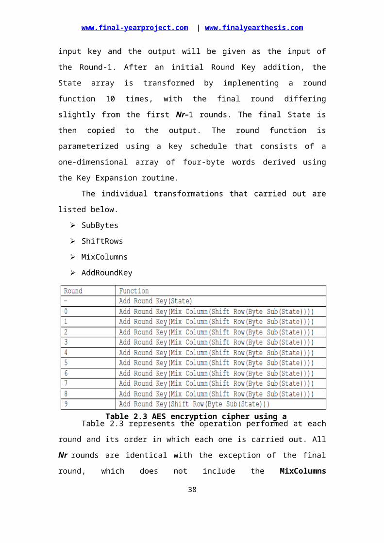
Table 2.3 represents the operation performed at each round and its order in
which each one is carried out. All Nr rounds are identical with the exception of the
final round, which does not include the MixColumns transformation. Thus the cipher
text, that is, encrypted data will be achieved at the end of the final round.
2.5.1 AES CIPHER FUNCTIONS
The block diagram shown in the figure 2.2 represents the functions carried out
in each round and the functions performed in the last round.
25
Table 2.3 AES encryption cipher using a 16 byte key
www.final-yearproject.com | www.finalyearthesis.com
26
Figure 2.2 Block Diagram for AES Round and AES Last Round
www.final-yearproject.com | www.finalyearthesis.com
2.5.1.1 SubBytes Transformation
The SubBytes operation is a non-linear byte substitution, operating on each
byte of the state independently. The substitution table (S-Box) is invertible and is
constructed by the composition of two transformations:
Take the multiplicative inverse in Rijndael's finite field
Apply an affine transformation
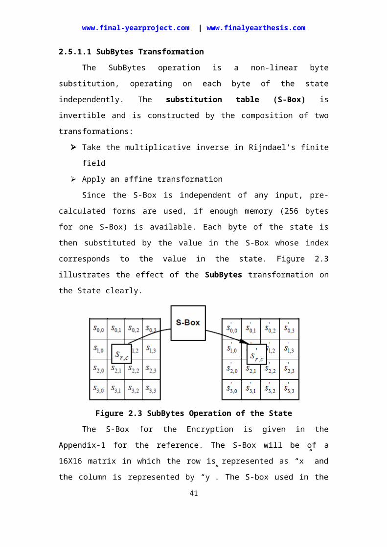
Since the S-Box is independent of any input, pre-calculated forms are used, if
enough memory (256 bytes for one S-Box) is available. Each byte of the state is then
substituted by the value in the S-Box whose index corresponds to the value in the
state. Figure 2.3 illustrates the effect of the SubBytes transformation on the State
clearly.
Figure 2.3 SubBytes Operation of the State
The S-Box for the Encryption is given in the Appendix-1 for the reference.
The S-Box will be of a 16X16 matrix in which the row is represented as “x” and the
column is represented by “y”. The S-box used in the SubBytes transformation is
presented in hexadecimal form and hence the substitution value would be determined
by the intersection of the row and the column.
For example, if S1,1 = {53}, then the substitution value would be determined
by the intersection of the row with index ‘5’ and the column with index ‘3’. This
would result in S1,1 having a value of {ed}. These values can be referred in the S-Box
present in the Appendix-1.
2.5.1.2 ShiftRows Transformation
Arranges the state in a matrix and then performs a circular shift for each row.
This is not a bit wise shift. The circular shift just moves each byte one space over. A
byte that was in the second position may end up in the third position after the shift.
27
www.final-yearproject.com | www.finalyearthesis.com
The circular part of it specifies that the byte in the last position shifted one space will
end up in the first position in the same row. Hence in this ShiftRows operation, each
row of the state is cyclically shifted to the left, depending on the row index. This has
the effect of moving bytes to “lower” positions in the row, while the “lowest” bytes
wrap around into the “top” of the row.
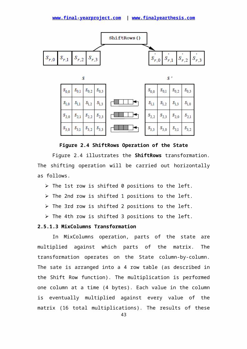
Figure 2.4 ShiftRows Operation of the State
Figure 2.4 illustrates the ShiftRows transformation. The shifting operation
will be carried out horizontally as follows.
The 1st row is shifted 0 positions to the left.
The 2nd row is shifted 1 positions to the left.
The 3rd row is shifted 2 positions to the left.
The 4th row is shifted 3 positions to the left.
2.5.1.3 MixColumns Transformation
In MixColumns operation, parts of the state are multiplied against which parts
of the matrix. The transformation operates on the State column-by-column. The sate is
arranged into a 4 row table (as described in the Shift Row function). The
multiplication is performed one column at a time (4 bytes). Each value in the column
is eventually multiplied against every value of the matrix (16 total multiplications).
The results of these multiplications are XORed together to produce only 4 result bytes
for the next state. There fore 4 bytes input, 16 multiplications 12 XORs and 4 bytes
28
www.final-yearproject.com | www.finalyearthesis.com
output. The multiplication is performed one matrix row at a time against each value of
a state column.
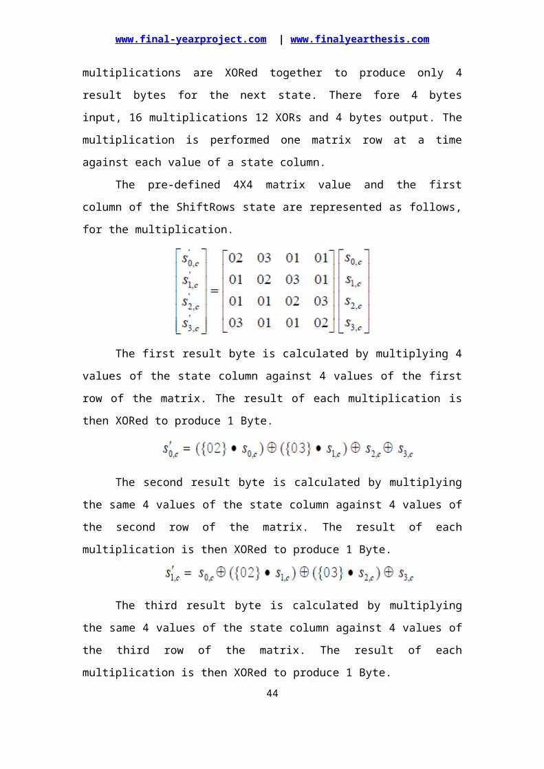
The pre-defined 4X4 matrix value and the first column of the ShiftRows state
are represented as follows, for the multiplication.
The first result byte is calculated by multiplying 4 values of the state column
against 4 values of the first row of the matrix. The result of each multiplication is then
XORed to produce 1 Byte.
The second result byte is calculated by multiplying the same 4 values of the
state column against 4 values of the second row of the matrix. The result of each
multiplication is then XORed to produce 1 Byte.
The third result byte is calculated by multiplying the same 4 values of the state
column against 4 values of the third row of the matrix. The result of each
multiplication is then XORed to produce 1 Byte.
The fourth result byte is calculated by multiplying the same 4 values of the
state column against 4 values of the fourth row of the matrix. The result of each
multiplication is then XORed to produce 1 Byte.
This procedure is repeated again with the next column of the state, until there
are no more state columns. Hence putting it all together, the first column will include
state bytes 1-4 and will be multiplied against the matrix in the following manner:
29

www.final-yearproject.com | www.finalyearthesis.com
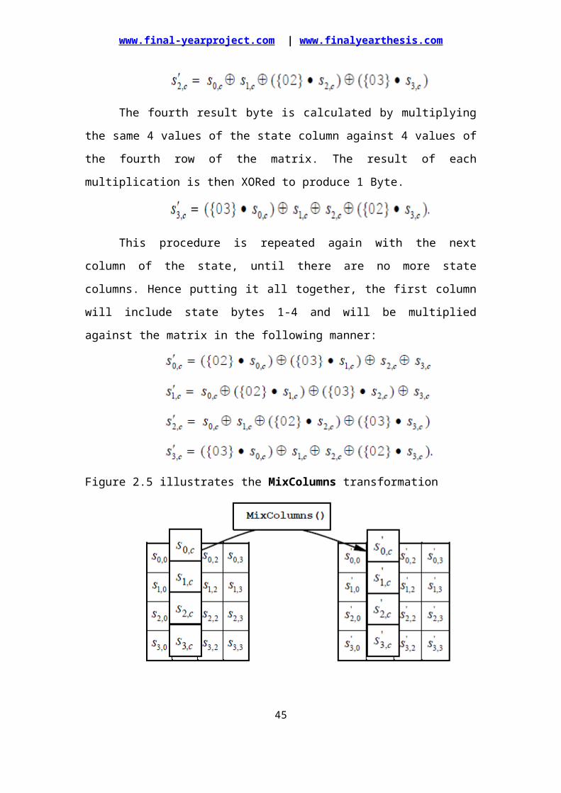
Figure 2.5 illustrates the MixColumns transformation
Figure 2.5 MixColumns operates on the State column-by-column
Hence the pictorial representation of the MixColumns operation represented
above gives the clear view on this transformation.
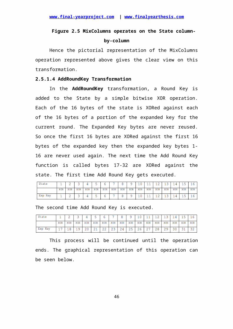
2.5.1.4 AddRoundKey Transformation
In the AddRoundKey transformation, a Round Key is added to the State by a
simple bitwise XOR operation. Each of the 16 bytes of the state is XORed against
each of the 16 bytes of a portion of the expanded key for the current round. The
Expanded Key bytes are never reused. So once the first 16 bytes are XORed against
the first 16 bytes of the expanded key then the expanded key bytes 1-16 are never
used again. The next time the Add Round Key function is called bytes 17-32 are
XORed against the state. The first time Add Round Key gets executed.
The second time Add Round Key is executed.
30
www.final-yearproject.com | www.finalyearthesis.com
This process will be continued until the operation ends. The graphical
representation of this operation can be seen below.
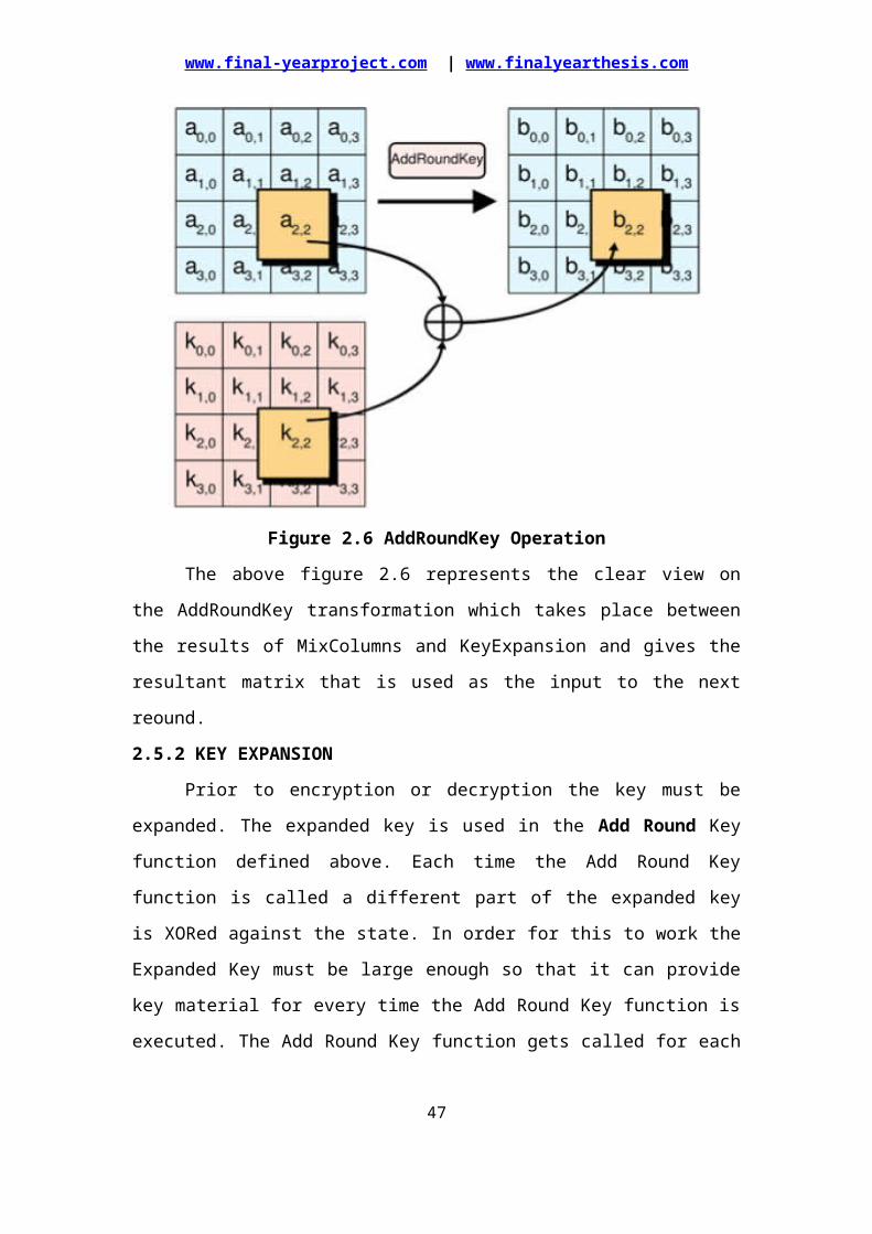
Figure 2.6 AddRoundKey Operation
The above figure 2.6 represents the clear view on the AddRoundKey
transformation which takes place between the results of MixColumns and
KeyExpansion and gives the resultant matrix that is used as the input to the next
reound.
2.5.2 KEY EXPANSION
Prior to encryption or decryption the key must be expanded. The expanded
key is used in the Add Round Key function defined above. Each time the Add Round
Key function is called a different part of the expanded key is XORed against the state.
In order for this to work the Expanded Key must be large enough so that it can
provide key material for every time the Add Round Key function is executed. The
Add Round Key function gets called for each round as well as one extra time at
beginning of the algorithm.
31

www.final-yearproject.com | www.finalyearthesis.com
The AES algorithm takes the Cipher Key, K, and performs a Key Expansion
routine to generate a key schedule. The Key Expansion generates a total of Nb (Nr +
1) words: the algorithm requires an initial set of Nb words, and each of the Nr rounds
requires Nb words of key data. The resulting key schedule consists of a linear array of
4-byte words.
Since the key size is much smaller than the size of the sub keys, the key is
actually “stretched out” to provide enough key space for the algorithm. Hence an 128
bit key is expanded to an 176 byte key.
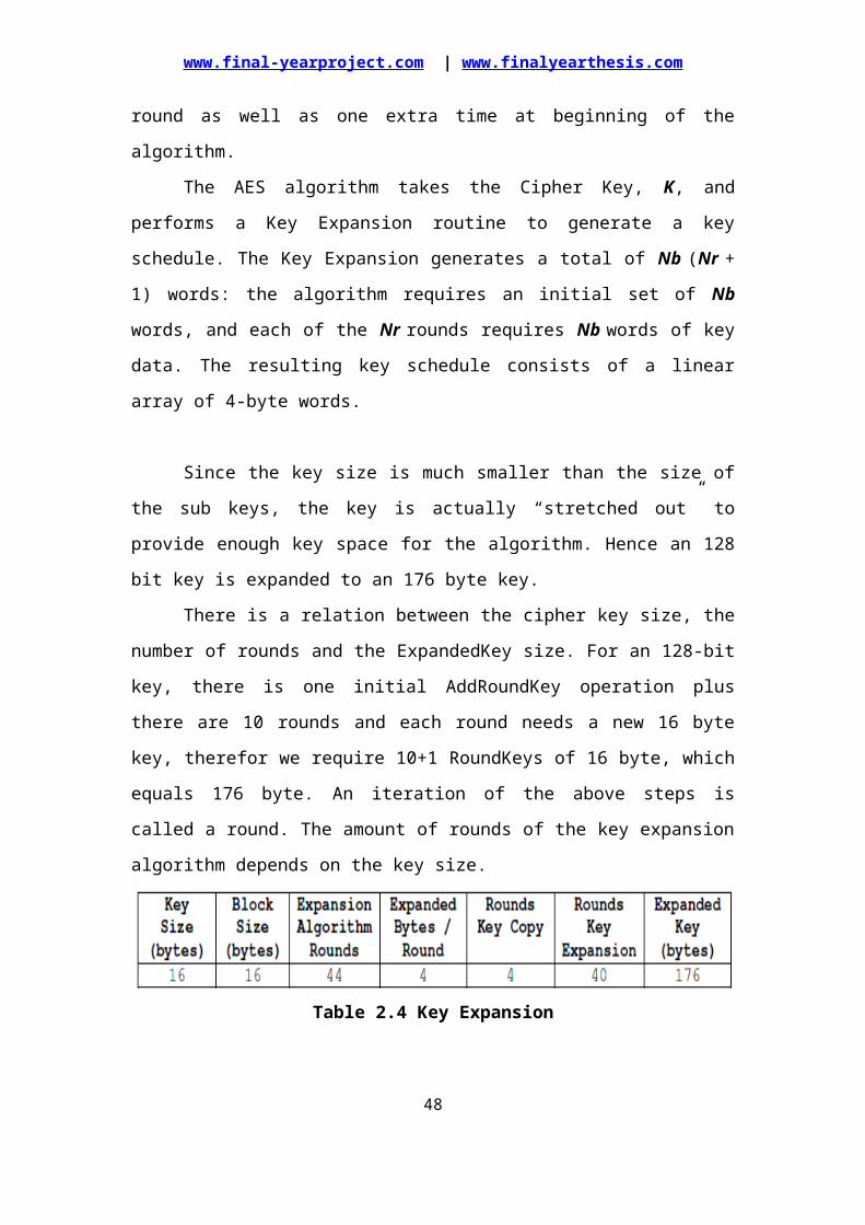
There is a relation between the cipher key size, the number of rounds and the
ExpandedKey size. For an 128-bit key, there is one initial AddRoundKey operation
plus there are 10 rounds and each round needs a new 16 byte key, therefor we require
10+1 RoundKeys of 16 byte, which equals 176 byte. An iteration of the above steps is
called a round. The amount of rounds of the key expansion algorithm depends on the
key size.
Table 2.4 Key Expansion
The first bytes of the expanded key are always equal to the key. If the key is
16 bytes long the first 16 bytes of the expanded key will be the same as the original
key. If the key size is 32 bytes then the first 32 bytes of the expanded key will be the
same as the original key. Each round adds 4 bytes to the Expanded Key. With the
exception of the first rounds each round also takes the previous rounds 4 bytes as
input operates and returns 4 bytes.
The key expansion routine executes a maximum of 4 consecutive functions.
These functions are:
ROT WORD
SUB WORD
RCON
XORRot Word (4 bytes)
32
www.final-yearproject.com | www.finalyearthesis.com
This does a circular shift on 4 bytes similar to the Shift Row Function. The 4-
byte word is cyclically shifted 1 byte to the left.
For Example, let’s take a sequence 1,2,3,4 which will be rotated and obtain the
result as 2,3,4,1.
Sub Word (4 bytes)
The Key Schedule uses the same S-Box substitution as the main algorithm
body. This step applies the S-box value substitution as described in SubBytes function
to each of the 4 bytes in the argument. The S-Box is present in the Appendix-1 for the
reference.
Rcon
Basically this function returns a 4 byte value based on the following table.
Round Number Rcon Value
1 Rcon(1) 01000000
2 Rcon(2) 02000000
3 Rcon(3) 04000000
4 Rcon(4) 08000000
5 Rcon(5) 10000000
6 Rcon(6) 20000000
7 Rcon(7) 40000000
8 Rcon(8) 80000000
9 Rcon(9) 1B000000
10 Rcon(10) 36000000
Table 2.5 Rcon Table
The result of the SubWords should be XORed with the above mentioned Rcon
values with respect to the corresponding round number. It can be seen that the first Nk
words of the expanded key are filled with the Cipher Key. Every following word,
w[i], is equal to the XOR of the previous word, w[i-1], and the word Nk positions
earlier, w[i-Nk]. For words in positions that are a multiple of Nk, a transformation is
applied to w[i-1] prior to the XOR, followed by an XOR with a round constant,
Rcon[i].
Steps in Key Expansion33
www.final-yearproject.com | www.finalyearthesis.com
The first n bytes of the expanded key are simply the cipher key (n = the size of
the encryption key)
The rcon value i is set to 1
Until we have enough bytes of expanded key, we do the following to generate
n more bytes of expanded key (please note once again that "n" is used here,
this varies depending on the key size)
1. we do the following to generate four bytes
we use a temporary 4-byte word called t
we assign the previous 4 bytes to t
we perform the key schedule core on t, with i as Rcon value
we increment i
we XOR t with the 4-byte word n bytes before in the
expandedKey (where n is once 16 bytes)
2. we do the following x times to generate the next x*4 bytes of the
expandedKey (x = 3 for n=16)
we assign the previous 4-byte word to t
we XOR t with the 4-byte word n bytes before in the
expandedKey (where n is once 16 bytes)
Hence, for n=16, we generate: 4 + 3*4 bytes = 16 bytes per iteration.
2.6 DECRYPTIONThe cipher text of 128 bits and the same key of 128 bits will be given as the
input to the decryption block. The encrypted data will be decrypted and the original
plain message will be achieved as the output of the decryption block. The Cipher
transformations can be inverted and then implemented in reverse order to produce a
straightforward Inverse Cipher for the AES algorithm. The individual transformations
used in the Inverse Cipher were listed as follows.
InvShiftRows
InvSubBytes
InvMixColumns
AddRoundKey
Here also 10 rounds will be carried out and the only difference in the
decryption block with respect to the algorithm flow is that the result of the
34
www.final-yearproject.com | www.finalyearthesis.com
KeyExpansion of each round will also be given to the MixCoulmns operation after
which the AddRoundKey transformation should be carried out.
InvMixColumns (state XOR Round Key) = InvMixColumns (state) XOR
InvMixColumns (Round Key)
The above equation represents the basic difference in the process of the AES
Encryption and Decryption algorithm.
2.6.1 AES INVERSE CIPHER FUNCTIONS
The AES Inverse Cipher Function has the same set of transformations as in the
encryption but in the inverse form, that is, the predefined values which used for the
each transformation will be different. In this section we can discuss about each
transformations in detail.
2.6.1.1 InvSubBytes Transformation
InvSubBytes is the inverse of the byte substitution transformation, in which
the inverse S-Box is applied to each byte of the State. The inverse S-Box is present in
the Appendix-1 for the reference. The transformation of this process will be carried
out in the similar way as in the SubBytes in the encryption such as the substitution
value would be determined by the intersection of the row and the column.
For example, if S1,1 = {53}, then the substitution value would be determined
by the intersection of the row with index ‘5’ and the column with index ‘3’. This
would result in S1,1 having a value of {50}. These values can be referred in the S-Box
present in the Appendix-1.
2.6.1.2 InvShiftRows Transformation
The InvShiftRows is the inverse of the ShiftRows transformation. The bytes in
the last three rows of the State are cyclically shifted over different numbers of bytes
(offsets). The first row, r = 0, is not shifted. The bottom three rows are cyclically
shifted by Nb - shift(r,Nb) bytes, where the shift value shift(r,Nb) depends on the row
number. Specifically, the InvShiftRows transformation proceeds as follows.
35
www.final-yearproject.com | www.finalyearthesis.com
Figure 2.7 InvShiftRows Operation of the State
The illustration figure will gives the clear view on this InvShiftRows
transformation.
2.6.1.3 InvMixColumns Transformation
The InvMixColumns is the inverse of the MixColumns transformation.
InvMixColumns operates on the State considering column-by-column. The pre-
defined 4X4 matrix value and the first column of the InvShiftRows state are
represented as follows, for the multiplication.
As a result of this multiplication, the four bytes in a column are replaced by
the following.
Thus the 4X4 matrix will be obtained which will be given as the input to the
next transformation.36
www.final-yearproject.com | www.finalyearthesis.com
2.6.1.4 Inverse of the AddRoundKey Transformation
The Inverse of the AddRoundKey is similar to the AddRoundKey in the
encryption process. Each element in the resultant matrix of MixColumns and resultant
matrix of KeyExpansion will be XORed and the resultant matrix of AddRoundKey
will be given as the input to the next round.
Hence all the inverse cipher transformations were discussed above and finally,
the only thing left to do is putting it all together in one inversed main algorithm.
Similarly the forward cipher transformations were combined together to form a
Round and combining all the 10 Rounds will constitute a complete AES Encryption
and Decryption algorithm.
2.7 SUMMARY Basic Terminologies and the Parameters used in this Algorithm have been
discussed at the earlier section.
Basic introduction and description on the AES Algorithm and its Top Level
Block Diagram was discussed.
Discussed on AES Encryption Process which includes AES Cipher Functions
and its transformation procedure.
Steps involved in the Key Expansion process were given.
AES Decryption Process which includes AES Inverse Cipher Functions was
explained.
37
www.final-yearproject.com | www.finalyearthesis.com
AES ALGORITHM IMPLEMENTATION
3.1 INTRODUCTIONThe AES is a block cipher. This means that the number of bytes that it
encrypts is fixed. AES can currently encrypt blocks of 16 bytes at a time; no other
block sizes are presently a part of the AES standard. If the bytes being encrypted are
larger than the specified block then AES is executed concurrently. This also means
that AES has to encrypt a minimum of 16 bytes. If the plain text is smaller than 16
bytes then it must be padded. Simply said the block is a reference to the bytes that are
processed by the algorithm.
The current condition of the block will be defined by the State. That is the
block of bytes that are currently being worked on. The state starts off being equal to
the block, however it changes as each round of the algorithms executes. Plainly we
can say that this is the block in progress. The Advanced Encryption Standard
Algorithm which includes both Encryption and Decryption are implemented using
VHDL and their functionality will be verified in the ModelSim Tool with proper test
cases.
3.2 IMPLEMENTATION REQUIREMENTSDuring the implementation, there are different parameters are required which
are discussed as follows.
Input Data Length Requirements
An implementation of the AES algorithm should have the input data (Plain
Text) length of 128 bits which acts as the primary input to the both Encryption and
Decryption block.
Key Length Requirements
In this AES implementation the input key chosen to be as 128 bits from the
various key lengths available. This also acts as the primary input to the both
Encryption and Decryption block.
Keying Restrictions
No weak or semi-weak keys have been identified for the AES algorithm and
there is no restriction on key selection.
38

www.final-yearproject.com | www.finalyearthesis.com
Parameterization of Block Size and Round Number
Here since the input data and the input key lengths are 128 bits, the block size
will be of Nb = 4 and the Round Number will be of Nr = 10. The Round Number will
be taken with respect to the AES Algorithm Standard.
3.3 NOTATION AND CONVENTIONSThe different notations and conventions were used in this implementation of
AES Algorithm.
HEX
Hexadecimal defines a notation of numbers in base 16. This simply means that
the highest number that can be represented in a single digit is 15, rather than the usual
9 in the decimal (base 10) system. Hence all the values were represented in the
Hexadecimal number system.
Inputs and Outputs
The input and output for the AES algorithm each consist of sequences of 128
bits (digits with values of 0 or 1). These sequences will sometimes be referred to as
blocks and the number of bits they contain will be referred to as their length. The
Cipher Key for the AES algorithm is a sequence of 128 bits. Other input and output
lengths are not permitted by this standard.
The bits within such sequences will be numbered starting at zero and ending at
one less than the sequence length (block length or key length). The number i attached
to a bit is known as its index and will be in one of the ranges 0 ≤ i < 128 depending on
the block length and key length (specified above).
Bytes
The basic unit for processing in the AES algorithm is a byte, a sequence of
eight bits treated as a single entity. The input, output and Cipher Key bit sequences
are processed as arrays of bytes that are formed by dividing these sequences into
groups of eight contiguous bits to form arrays of bytes. For an input, output or Cipher
Key denoted by a, the bytes in the resulting array will be referenced using one of the
two forms, “an” or a[n], where n will be in one of the following ranges.
Key length = 128 bits, 0 ≤ n < 16
Block length = 128 bits, 0 ≤n < 16
39

www.final-yearproject.com | www.finalyearthesis.com
State
Internally, the AES algorithm’s operations are performed on a two-
dimensional array of bytes called the State. The State consists of four rows of bytes,
each containing Nb bytes, where Nb is the block length divided by 32. In the State
array denoted by the symbol s, each individual byte has two indices, with its row
number r in the range 0 ≤ r < 4 and its column number c in the range 0 ≤ c < Nb. This
allows an individual byte of the State to be referred to as either sr,c or s[r,c]. For this
standard, Nb =4, i.e., 0 ≤ c < 4.
At the start of the Cipher and Inverse Cipher, the input (the array of bytes in0,
in1, … in15) will be copied into the State array. The Cipher or Inverse Cipher
operations are then conducted on this State array, after which its final value is copied
to the output will be the array of bytes out0, out1, … out15.
Figure 3.1 State Array Input and Output
Hence, at the beginning of the Cipher or Inverse Cipher, the input array, in, is
copied to the State array according to the scheme:
s[r, c] = in[r + 4c] for 0 ≤ r < 4 and 0 ≤ c < Nb,
And at the end of the Cipher and Inverse Cipher, the State is copied to the output
array out as follows:
out[r + 4c] = s[r, c] for 0 ≤ r < 4 and 0 ≤ c < Nb.
State as an Array of Columns
The four bytes in each column of the State array form 32-bit words, where the
row number r provides an index for the four bytes within each word. The state can
hence be interpreted as a one-dimensional array of 32 bit words (columns), w0...w3,
where the column number c provides an index into this array. Hence the State can be
considered as an array of four words, as follows:
w0 = s0,0 s1,0 s2,0 s3,0 w2 = s0,2 s1,2 s2,2 s3,240
www.final-yearproject.com | www.finalyearthesis.com
w1 = s0,1 s1,1 s2,1 s3,1 w3 = s0,3 s1,3 s2,3 s3,3
3.4 MATHEMATICAL PRELIMINARIESAll bytes in the AES algorithm are interpreted as finite field elements that can
be added and multiplied, but these operations are different from those used for
numbers.
Addition
The addition of two elements in a finite field is achieved by “adding” the
coefficients for the corresponding powers in the polynomials for the two elements.
The addition is performed with the XOR operation (denoted by ). For example, two
hexadecimal numbers have been taken and the addition, that is, XOR operation has
performed.
{57} {83} = {d4}
Multiplication
The modular product of a(x) and b(x), denoted by a(x) b(x), is given by d(x)
which are given as follow.
The matrix of 4X4 is taken and is multiplied with the single column, that is,
matrix multiplication has to be performed.
The multiplication of the above matrix can be performed in the following
manner.
41
www.final-yearproject.com | www.finalyearthesis.com
3.5 GENERAL IMPLEMENTATION FLOWThe generalized implementation flow diagram of the project is represented as
follows.
Figure 3.2 General Implementation Flow Diagram
Initially the market research should be carried out which covers the previous
version of the design and the current requirements on the design. Based on this
42
www.final-yearproject.com | www.finalyearthesis.com
survey, the specification and the architecture must be identified. Then the RTL
modeling should be carried out in VHDL with respect to the identified architecture.
Once the RTL modeling is done, it should be simulated and verified for all the cases.
The functional verification should meet the intended architecture and should pass all
the test cases.
Once the functional verification is clear, the RTL model will be taken to the
synthesis process. Three operations will be carried out in the synthesis process such as
Translate
Map
Place and Route
The developed RTL model will be translated to the mathematical equation
format which will be in the understandable format of the tool. These translated
equations will be then mapped to the library that is, mapped to the hardware. Once the
mapping is done, the gates were placed and routed. Before these processes, the
constraints can be given in order to optimize the design. Finally the BIT MAP file will
be generated that has the design information in the binary format which will be
dumped in the FPGA board.
3.6 IMPLEMENTATIONThe project deals with both the Encryption and Decryption algorithm and its
operation.
RTL Modeling
The implementation of the encryption and decryption should be differentiated
and the system must know which one it should perform. So a signal
“Enc_Dec” is declared which will represents the operation of the system, that
is, system is either in encryption or decryption.
The given input data and key will be converted to a State and Word for the
further transformation.
For accessing the State, that is, 4X4 array, two loops have been used with the
naming convention of ‘i’ and ‘j’.
KeyExpansion
The implementation of AES with the Cipher Key expansion, that is to enlarge
our input cipher key, whose size is 128 bits into a larger key, from which
different RoundKeys can be derived.43
www.final-yearproject.com | www.finalyearthesis.com
The S-Box values can either be calculated on-the-fly to save memory or the
pre-calculated values can be stored in an array. There are 2 S-Boxes, one for
the encryption and one for the decryption whose values will store the values in
an array. Additionally, instead of accessing the values immediately from the
program, it got wrap a little function around which makes for a more readable
code and would allow us to add additional code later on. In the
implementation of the 2 S-Boxes, it's only a table-lookup that returns the value
in the array whose index is specified as a parameter of the function.
From the theoretical part, it is known already that Rotate takes a word (a 4-
byte array) and rotates it 8 bit to the left. Since 8 bit correspond to one byte
and the array type is character (whose size is one byte), rotating 8 bit to the
left corresponds to shifting cyclically the array values one to the left.
The implementation of Rcon is done with respect to the counter. The counter
is set with respect to round number and the Rcon value will be calculated by
performing the multiplication operation between the input value and constant
value.
The Key Expansion is where it all comes together. As you can see in the pretty
big list in the theory about the Rijndael Key Expansion, we need to apply
several operations a number of times, depending on they key size.
KeyExpansion function basically needs only two things:
o Input cipher key
o Output expanded key
All the operations should be applied one after the other on the 4-byte word
which does the complete operation. The parameters are the 4-byte word and
the iteration counter, on which Rcon depends. Hence this KeyExpansion will
be calculated and each 16 bytes will be given to each Round.
AES Encryption
To implement the AES encryption algorithm, we proceed exactly the same
way as for the key expansion, that is, we first implement the basic helper
functions and then move up to the main loop. The functions take as parameter
a state, which is, as already explained, a rectangular 4x4 array of bytes.
44
www.final-yearproject.com | www.finalyearthesis.com
The shiftRows function iterates over all the rows and then call shiftRow with
the correct offset. shiftRow does nothing but to shift a 4-byte array by the
given offset.
This is the part that involves the roundKey was generated during each
iteration. Here simply XOR each byte of the key to the respective byte of the
state
The MixColumns implementation was carried out by first one would generate
a column and then call mixColumn, which would then apply the matrix
multiplication.
As you can see in the theory, one AES round is the one which has to apply all
four operations on the state consecutively. All we have to do is take the state,
the ExpandedKey and the number of rounds as parameters and then call the
operations one after the other.
Finally, all we have to do is put it all together. Our parameters are the input
plaintext, the key of size keySize and the output. First, we calculate the
number of rounds based on they keySize and then the expandedKeySize based
on the number of rounds. Then we have to map the 16 byte input plaintext in
the correct order to the 4x4 byte state (as explained above), expand the key
using our key schedule, encrypt the state using our main AES body and finally
un-map the state again in the correct order in order to get the 16 byte output
ciphertext.
AES Decryption
For the AES Decryption, the key schedule stays the same, the only operations
we need to implement are the inversed subBytes, shiftRows and mixColumns,
while addRoundKey stays the same.
As you can see, they are nearly identical to their encryption except that the
rotation this time is to the right and that we use the inversed S-Box for the
substitution. As for the inversed mixColumns operation, the only difference is
the multiplication matrix is different.
Finally, the only thing left to do is putting it all together in one inversed main
algorithm. Please note that we use our expanded key backwards, starting with
the last 16 bytes and then moving towards the start.
45
www.final-yearproject.com | www.finalyearthesis.com
The separate modules were written for the Last Round and other Rounds.
From first round to ninth round the same module can be instantiated and for
the last round, a separate module was used since it doesn’t have the
MixColumns operation.
The functional verification was carried out for all the test cases and hence the
RTL modeling is taken to the synthesis process using the Xilinx tool.
Synthesis Process
The synthesis process will be carried out by giving the RTL model as the input
to the tool. This RTL modeling requires Virtex-2 board for the
implementation.
Hence the Virtex-2 board is selected and the whole process flow will be
carried out in the Xilinx tool and finally the BIT FILE is generated which is
used for dumping on the board.
3.7 SUMMARY The implementation requirement which includes the primary input and
primary output of the design and the proper notation and conventions were
discussed.
General implementation flow of the design were represented and explained in
order to understand the proper flow.
Implementation details have been discussed which includes implementation
style of each process.
Finally the synthesis process was discussed which gives that in which FPGA
family, the design has been implemented.
46
www.final-yearproject.com | www.finalyearthesis.com
4.CODING4.CODING-- ============================================================================== ---- 4.1 ADVANCED ENCRYPTION STANDARD-- ============================---- PACKAGE OF FUNCTIONS REQUIRED FOR AES ALGORITHM-- ============================================================================== --
library ieee;use ieee.std_logic_1164.all;use ieee.std_logic_unsigned.all;
package AES_PACK_128 is
constant NB : integer := 4;
subtype BYTE is std_logic_vector(7 downto 0);
type ROW_COL_TYPE is array (0 to NB-1,0 to NB-1) of integer range 0 to 15;type WORD is array (0 to NB-1) of BYTE;type XARRAY is array (0 to 7 ) of BYTE;type S_TYPE is array (0 to 15,0 to 15) of BYTE;type STATE_TYPE is array (0 to NB-1,0 to NB-1) of BYTE;type KEY_TYPE is array (0 to 3,0 to NB-1) of BYTE;type EXP_KEY_TYPE is array (0 to (11*NB)-1,0 to NB-1) of BYTE;
function XTIME(INPUT:BYTE) return BYTE;function DOT(IN1,IN2:BYTE) return BYTE;function SUBBYTES(INPUT_VEC:STATE_TYPE;ENC_DEC:std_logic)return STATE_TYPE;function SHIFTROWS(INPUT_VEC:STATE_TYPE;ENC_DEC:std_logic) return STATE_TYPE;function MIXCOL(INPUT_VEC:STATE_TYPE;ENC_DEC:std_logic) return STATE_TYPE;function ADDROUNDKEY(INPUT_VEC,ROUNDKEY:STATE_TYPE) return STATE_TYPE;function ROTWORD(KEYWORD : WORD) return WORD;function SUBWORD(KEYWORD : WORD;ENC_DEC:std_logic) return WORD;function KEY_EXP(KEY_IN:KEY_TYPE; NK:integer;ENC_DEC:std_logic) return EXP_KEY_TYPE;function WORD2STATE(INPUT:EXP_KEY_TYPE;ROUND_NUM:integer) return STATE_TYPE;function BITS2KEY(INPUT:std_logic_vector(0 to 127)) return KEY_TYPE;function BITS2STATE(INPUT:std_logic_vector(0 to 127)) return STATE_TYPE;function STATE2BITS(INPUT:STATE_TYPE) return std_logic_vector;
end AES_PACK_128;
47
www.final-yearproject.com | www.finalyearthesis.com
package body AES_PACK_128 is
-- ************** FUNCTION FOR MULTIPLY BY {02} MOD {01}{1b} **************** --
function XTIME(INPUT:BYTE) return BYTE isconstant MX:BYTE := "00011011"; --m(x) = {01}{1b}variable OUTPUT:BYTE;beginif (INPUT(7)= '1') thenOUTPUT := (INPUT(6 downto 0) & '0') xor MX;elseOUTPUT := (INPUT(6 downto 0) & '0');end if;return OUTPUT;end XTIME;
-- ************** FUNCTION FOR DOT MULTIPLICATION **************** --
function DOT(IN1,IN2:BYTE) return BYTE isvariable X : XARRAY;variable OUTPUT : BYTE;beginX(0) := IN1;
-- {IN1}.{01}X(1) := XTIME(X(0)); -- {IN1}.{02}X(2) := XTIME(X(1)); -- {IN1}.{04}X(3) := XTIME(X(2)); -- {IN1}.{08}X(4) := XTIME(X(3)); -- {IN1}.{10}X(5) := XTIME(X(4)); -- {IN1}.{20}X(6) := XTIME(X(5)); -- {IN1}.{40}X(7) := XTIME(X(6)); -- {IN1}.{80}OUTPUT := (others =>'0'); -- Initialize OUTPUT Accumulator to zero.
for i in 7 downto 0 loopif(IN2(i) = '1') thenOUTPUT := OUTPUT xor X(i);end if;end loop;return OUTPUT;end DOT;
-- ************ FUNCTION FOR SUBBYTE / INVERSE SUBBYTES CALCULATION ************* --
function SUBBYTES(INPUT_VEC:STATE_TYPE;ENC_DEC:std_logic)return STATE_TYPE is-- 0 1 2 3 4 5 6 7 8 9 a b c d e fconstant S_BOX : S_TYPE :=((("01100011"), ("01111100"), ("01110111"), ("01111011"), ("11110010"), ("01101011"), ("01101111"), ("11000101"), ("00110000"), ("00000001"),
48
www.final-yearproject.com | www.finalyearthesis.com
("01100111"), ("00101011"), ("11111110"), ("11010111"), ("10101011"), ("01110110")), -- 0 --(("11001010"), ("10000010"), ("11001001"), ("01111101"), ("11111010"), ("01011001"), ("01000111"), ("11110000"), ("10101101"), ("11010100"), ("10100010"), ("10101111"), ("10011100"), ("10100100"), ("01110010"), ("11000000")), -- 1 --(("10110111"), ("11111101"), ("10010011"), ("00100110"), ("00110110"), ("00111111"), ("11110111"), ("11001100"), ("00110100"), ("10100101"), ("11100101"), ("11110001"), ("01110001"), ("11011000"), ("00110001"), ("00010101")), -- 2 --(("00000100"), ("11000111"), ("00100011"), ("11000011"), ("00011000"), ("10010110"), ("00000101"), ("10011010"), ("00000111"), ("00010010"), ("10000000"), ("11100010"), ("11101011"), ("00100111"), ("10110010"), ("01110101")), -- 3 --(("00001001"), ("10000011"), ("00101100"), ("00011010"), ("00011011"), ("01101110"), ("01011010"), ("10100000"), ("01010010"), ("00111011"), ("11010110"), ("10110011"), ("00101001"), ("11100011"), ("00101111"), ("10000100")), -- 4 --(("01010011"), ("11010001"), ("00000000"), ("11101101"), ("00100000"), ("11111100"), ("10110001"), ("01011011"), ("01101010"), ("11001011"), ("10111110"), ("00111001"), ("01001010"), ("01001100"), ("01011000"), ("11001111")), -- 5 --(("11010000"), ("11101111"), ("10101010"), ("11111011"), ("01000011"), ("01001101"), ("00110011"), ("10000101"), ("01000101"), ("11111001"), ("00000010"), ("01111111"), ("01010000"), ("00111100"), ("10011111"), ("10101000")), -- 6 --(("01010001"), ("10100011"), ("01000000"), ("10001111"), ("10010010"), ("10011101"), ("00111000"), ("11110101"), ("10111100"), ("10110110"), ("11011010"), ("00100001"), ("00010000"), ("11111111"), ("11110011"), ("11010010")), -- 7 --(("11001101"), ("00001100"), ("00010011"), ("11101100"), ("01011111"), ("10010111"), ("01000100"), ("00010111"), ("11000100"), ("10100111"), ("01111110"), ("00111101"), ("01100100"), ("01011101"), ("00011001"), ("01110011")), -- 8 --(("01100000"), ("10000001"), ("01001111"), ("11011100"), ("00100010"), ("00101010"), ("10010000"), ("10001000"), ("01000110"), ("11101110"), ("10111000"), ("00010100"), ("11011110"), ("01011110"), ("00001011"), ("11011011")), -- 9 --(("11100000"), ("00110010"), ("00111010"), ("00001010"), ("01001001"), ("00000110"), ("00100100"), ("01011100"), ("11000010"), ("11010011"), ("10101100"), ("01100010"), ("10010001"), ("10010101"), ("11100100"), ("01111001")), -- a --(("11100111"), ("11001000"), ("00110111"), ("01101101"), ("10001101"), ("11010101"), ("01001110"), ("10101001"), ("01101100"), ("01010110"), ("11110100"), ("11101010"), ("01100101"), ("01111010"), ("10101110"), ("00001000")), -- b --
49

www.final-yearproject.com | www.finalyearthesis.com
(("10111010"), ("01111000"), ("00100101"), ("00101110"), ("00011100"), ("10100110"), ("10110100"), ("11000110"), ("11101000"), ("11011101"), ("01110100"), ("00011111"), ("01001011"), ("10111101"), ("10001011"), ("10001010")), -- c --(("01110000"), ("00111110"), ("10110101"), ("01100110"), ("01001000"), ("00000011"), ("11110110"), ("00001110"), ("01100001"), ("00110101"), ("01010111"), ("10111001"), ("10000110"), ("11000001"), ("00011101"), ("10011110")), -- d --(("11100001"), ("11111000"), ("10011000"), ("00010001"), ("01101001"), ("11011001"), ("10001110"), ("10010100"), ("10011011"), ("00011110"), ("10000111"), ("11101001"), ("11001110"), ("01010101"), ("00101000"), ("11011111")), -- e --(("10001100"), ("10100001"), ("10001001"), ("00001101"), ("10111111"), ("11100110"), ("01000010"), ("01101000"), ("01000001"), ("10011001"), ("00101101"), ("00001111"), ("10110000"), ("01010100"), ("10111011"), ("00010110"))); -- f --
-- 0 1 2 3 4 5 6 7 8 9 a b c d e fconstant INV_S_BOX : S_TYPE :=((("01010010"), ("00001001"), ("01101010"), ("11010101"), ("00110000"), ("00110110"), ("10100101"), ("00111000"), ("10111111"), ("01000000"), ("10100011"), ("10011110"), ("10000001"), ("11110011"), ("11010111"), ("11111011")), -- 0 --(("01111100"), ("11100011"), ("00111001"), ("10000010"), ("10011011"), ("00101111"), ("11111111"), ("10000111"), ("00110100"), ("10001110"), ("01000011"), ("01000100"), ("11000100"), ("11011110"), ("11101001"), ("11001011")), -- 1 --(("01010100"), ("01111011"), ("10010100"), ("00110010"), ("10100110"), ("11000010"), ("00100011"), ("00111101"), ("11101110"), ("01001100"), ("10010101"), ("00001011"), ("01000010"), ("11111010"), ("11000011"), ("01001110")), -- 2 --(("00001000"), ("00101110"), ("10100001"), ("01100110"), ("00101000"), ("11011001"), ("00100100"), ("10110010"), ("01110110"), ("01011011"), ("10100010"), ("01001001"), ("01101101"), ("10001011"), ("11010001"), ("00100101")), -- 3 --(("01110010"), ("11111000"), ("11110110"), ("01100100"), ("10000110"), ("01101000"), ("10011000"), ("00010110"), ("11010100"), ("10100100"), ("01011100"), ("11001100"), ("01011101"), ("01100101"), ("10110110"), ("10010010")), -- 4 --(("01101100"), ("01110000"), ("01001000"), ("01010000"), ("11111101"), ("11101101"), ("10111001"), ("11011010"), ("01011110"), ("00010101"), ("01000110"), ("01010111"), ("10100111"), ("10001101"), ("10011101"), ("10000100")), -- 5 --(("10010000"), ("11011000"), ("10101011"), ("00000000"), ("10001100"), ("10111100"), ("11010011"), ("00001010"),
50
www.final-yearproject.com | www.finalyearthesis.com
("11110111"), ("11100100"), ("01011000"), ("00000101"), ("10111000"), ("10110011"), ("01000101"), ("00000110")), -- 6 --(("11010000"), ("00101100"), ("00011110"), ("10001111"), ("11001010"), ("00111111"), ("00001111"), ("00000010"), ("11000001"), ("10101111"), ("10111101"), ("00000011"), ("00000001"), ("00010011"), ("10001010"), ("01101011")), -- 7 --(("00111010"), ("10010001"), ("00010001"), ("01000001"), ("01001111"), ("01100111"), ("11011100"), ("11101010"), ("10010111"), ("11110010"), ("11001111"), ("11001110"), ("11110000"), ("10110100"), ("11100110"), ("01110011")), -- 8 --(("10010110"), ("10101100"), ("01110100"), ("00100010"), ("11100111"), ("10101101"), ("00110101"), ("10000101"), ("11100010"), ("11111001"), ("00110111"), ("11101000"), ("00011100"), ("01110101"), ("11011111"), ("01101110")), -- 9 --(("01000111"), ("11110001"), ("00011010"), ("01110001"), ("00011101"), ("00101001"), ("11000101"), ("10001001"), ("01101111"), ("10110111"), ("01100010"), ("00001110"), ("10101010"), ("00011000"), ("10111110"), ("00011011")), -- a --(("11111100"), ("01010110"), ("00111110"), ("01001011"), ("11000110"), ("11010010"), ("01111001"), ("00100000"), ("10011010"), ("11011011"), ("11000000"), ("11111110"), ("01111000"), ("11001101"), ("01011010"), ("11110100")), -- b --(("00011111"), ("11011101"), ("10101000"), ("00110011"), ("10001000"), ("00000111"), ("11000111"), ("00110001"), ("10110001"), ("00010010"), ("00010000"), ("01011001"), ("00100111"), ("10000000"), ("11101100"), ("01011111")), -- c --(("01100000"), ("01010001"), ("01111111"), ("10101001"), ("00011001"), ("10110101"), ("01001010"), ("00001101"), ("00101101"), ("11100101"), ("01111010"), ("10011111"), ("10010011"), ("11001001"), ("10011100"), ("11101111")), -- d --(("10100000"), ("11100000"), ("00111011"), ("01001101"), ("10101110"), ("00101010"), ("11110101"), ("10110000"), ("11001000"), ("11101011"), ("10111011"), ("00111100"), ("10000011"), ("01010011"), ("10011001"), ("01100001")), -- e --(("00010111"), ("00101011"), ("00000100"), ("01111110"), ("10111010"), ("01110111"), ("11010110"), ("00100110"), ("11100001"), ("01101001"), ("00010100"), ("01100011"), ("01010101"), ("00100001"), ("00001100"), ("01111101"))); -- f --constant C_ENC : BYTE :="01100011";variable OUTPUT : STATE_TYPE;variable ROW : ROW_COL_TYPE;variable COL : ROW_COL_TYPE;beginfor i in 0 to 3 loopfor j in 0 to 3 loopROW(i,j):= conv_integer(INPUT_VEC(i,j)(7 downto 4));COL(i,j):= conv_integer(INPUT_VEC(i,j)(3 downto 0));
51
www.final-yearproject.com | www.finalyearthesis.com
end loop;end loop;for i in 0 to 3 loopfor j in 0 to 3 loopif (ENC_DEC = '1') thenOUTPUT(i,j) := S_BOX(ROW(i,j),COL(i,j));elseOUTPUT(i,j) := INV_S_BOX(ROW(i,j),COL(i,j));end if;end loop;end loop;return OUTPUT;end SUBBYTES;
-- ************** FUNCTION FOR SHIFTING / INVERSE SHIFTING OF ROWS ************** --
function SHIFTROWS(INPUT_VEC:STATE_TYPE;ENC_DEC:std_logic) return STATE_TYPE isvariable OUT_VEC:STATE_TYPE;variable COL: integer range 0 to 3;beginfor i in 0 to 3 loopOUT_VEC(i,0) := INPUT_VEC(i,0); -- Here 'i' is Columnend loop;for j in 1 to 3 loopfor k in 0 to 3 loopif (ENC_DEC = '1') thenif (j+k<=NB-1) thenCOL := j+k;elseCOL := j+k-NB;end if;elseif (k-j>=0) thenCOL := k-j;elseCOL := NB-j+k;end if;end if;OUT_VEC(k,j) := INPUT_VEC(COL,j);end loop;end loop;return OUT_VEC;end SHIFTROWS;
-- ************** FUNCTION FOR MIXING / INVERSE MIXING OF COLUMNS *************** --
function MIXCOL(INPUT_VEC:STATE_TYPE;ENC_DEC:std_logic) return STATE_TYPE isconstant A : WORD := (("00000010"),("00000001"),("00000001"),("00000011"));constant A_INV : WORD := (("00001110"),("00001001"),("00001101"),("00001011"));variable OUT_VEC: STATE_TYPE;
52
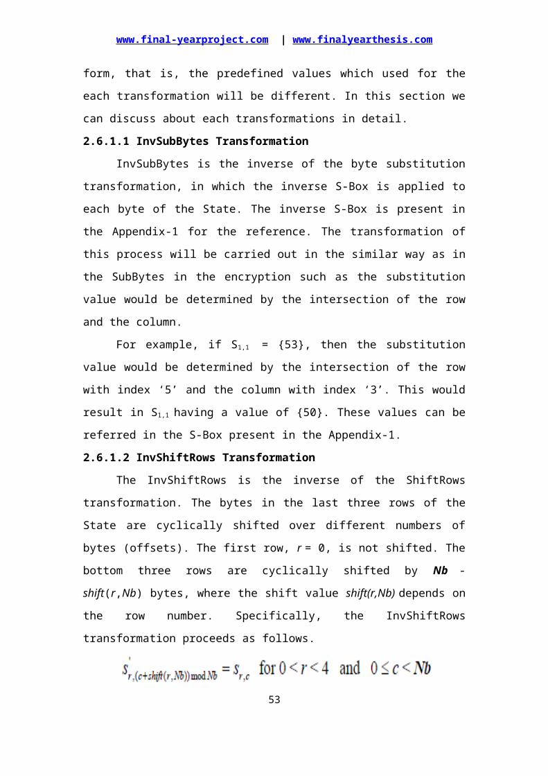
www.final-yearproject.com | www.finalyearthesis.com
variable MUXOUT : WORD;beginif (ENC_DEC = '1') thenMUXOUT := A;elseMUXOUT := A_INV;end if;for i in 0 to 3 loopOUT_VEC(i,0) := DOT(MUXOUT(0),INPUT_VEC(i,0)) xor DOT(MUXOUT(3),INPUT_VEC(i,1)) xor DOT(MUXOUT(2),INPUT_VEC(i,2)) xor DOT(MUXOUT(1),INPUT_VEC(i,3));OUT_VEC(i,1) := DOT(MUXOUT(1),INPUT_VEC(i,0)) xor DOT(MUXOUT(0),INPUT_VEC(i,1)) xor DOT(MUXOUT(3),INPUT_VEC(i,2)) xor DOT(MUXOUT(2),INPUT_VEC(i,3));OUT_VEC(i,2) := DOT(MUXOUT(2),INPUT_VEC(i,0)) xor DOT(MUXOUT(1),INPUT_VEC(i,1)) xor DOT(MUXOUT(0),INPUT_VEC(i,2)) xor DOT(MUXOUT(3),INPUT_VEC(i,3));OUT_VEC(i,3) := DOT(MUXOUT(3),INPUT_VEC(i,0)) xor DOT(MUXOUT(2),INPUT_VEC(i,1)) xor DOT(MUXOUT(1),INPUT_VEC(i,2)) xor DOT(MUXOUT(0),INPUT_VEC(i,3));end loop; return OUT_VEC;end MIXCOL;
-- ************** FUNCTION FOR ADDING ROUND KEYS **************** --
function ADDROUNDKEY(INPUT_VEC,ROUNDKEY:STATE_TYPE) return STATE_TYPE isvariable OUT_VEC:STATE_TYPE;beginfor i in 0 to 3 loopfor j in 0 to 3 loopOUT_VEC(i,j) := INPUT_VEC(i,j) xor ROUNDKEY(i,j);end loop;end loop;return OUT_VEC;end ADDROUNDKEY;
-- ************** FUNCTION FOR WORD ROTATION **************** --
function ROTWORD(KEYWORD : WORD) return WORD isvariable OUT_KEY : WORD;beginOUT_KEY(0) := KEYWORD(1);OUT_KEY(1) := KEYWORD(2);OUT_KEY(2) := KEYWORD(3);OUT_KEY(3) := KEYWORD(0);return OUT_KEY;end ROTWORD;
-- ************** FUNCTION FOR SUB WORD **************** --
function SUBWORD(KEYWORD : WORD;ENC_DEC:std_logic) return WORD isvariable OUT_KEY : WORD;variable IN_STATE : STATE_TYPE;
53
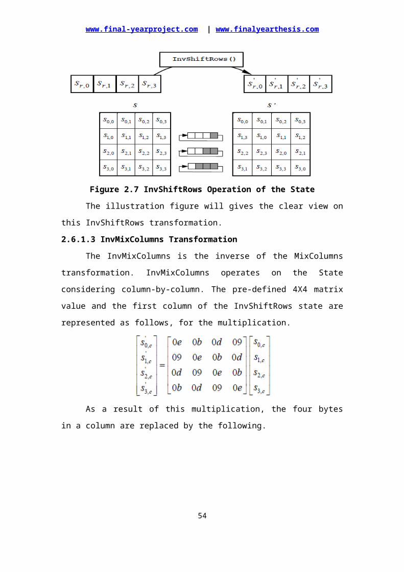
www.final-yearproject.com | www.finalyearthesis.com
variable OUT_STATE : STATE_TYPE;beginfor i in 0 to 3 loopfor j in 0 to 3 loopIN_STATE(i,j) := KEYWORD(i);end loop;end loop;OUT_STATE := SUBBYTES(IN_STATE,ENC_DEC);for i in 0 to 3 loopOUT_KEY(i) := OUT_STATE(i,0);end loop;return OUT_KEY;end SUBWORD;
-- ************** FUNCTION FOR KEY EXPANSION **************** --
function KEY_EXP(KEY_IN:KEY_TYPE; NK:integer ;ENC_DEC:std_logic) return EXP_KEY_TYPE isconstant NR : integer :=10 ;constant RCON : BYTE := "00000001";variable ENC_KEY : EXP_KEY_TYPE;variable DEC_KEY : EXP_KEY_TYPE;variable TEMP1 : WORD;variable TEMP2 : BYTE;beginENC_KEY := (others =>(others =>(others =>'0')));DEC_KEY := (others =>(others =>(others =>'0')));TEMP2 := RCON;for c in 0 to 3 loop -- columnfor r in 0 to 3 loop -- rowENC_KEY(c,r) := KEY_IN(c,r);end loop;end loop;for c in 4 to 43 loopfor r in 0 to 3 loopTEMP1(r) := ENC_KEY((c-1),r);end loop;if ((c mod 4) = 0) thenTEMP1 := SUBWORD(ROTWORD(TEMP1),'1');TEMP1(0) := TEMP1(0) xor TEMP2;TEMP2 := XTIME(TEMP2);end if;for r in 0 to 3 loopENC_KEY(c,r):= (ENC_KEY((c-4),r) xor TEMP1(r));end loop;end loop;for i in 0 to 10 loopfor c in 0 to 3 loop -- columnfor r in 0 to 3 loop -- rowDEC_KEY(NB*(NR-i)+c,r) := ENC_KEY(NB*i+c,r);end loop;end loop;end loop;if (ENC_DEC = '1') thenreturn ENC_KEY;else
54
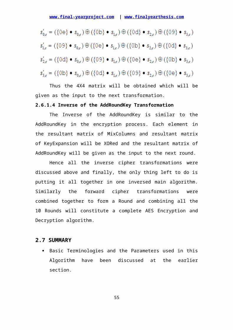
www.final-yearproject.com | www.finalyearthesis.com
return DEC_KEY;end if;end KEY_EXP;
-- ************ FUNCTION FOR WORD TO STATE CONVERSION ************* --
function WORD2STATE(INPUT:EXP_KEY_TYPE;ROUND_NUM:integer) return STATE_TYPE isvariable OUTPUT : STATE_TYPE;beginfor i in 0 to 3 loopfor j in 0 to 3 loopOUTPUT(i,j) := INPUT(ROUND_NUM*NB+i,j);end loop;end loop;return OUTPUT;end WORD2STATE;
-- ************ FUNCTION FOR BITS TO KEY CONVERSION *************** --
function BITS2KEY(INPUT:std_logic_vector(0 to 127)) return KEY_TYPE isvariable OUTPUT : KEY_TYPE;beginfor i in 0 to 3 loopfor j in 0 to 3 loopfor k in 7 downto 0 loopOUTPUT(i,j)(7-k) := INPUT(i * NB * 8 + j * 8 + k);end loop;end loop;end loop;return OUTPUT;end BITS2KEY;
-- ************ FUNCTION FOR BITS TO STATE CONVERSION ************* --
function BITS2STATE(INPUT:std_logic_vector(0 to 127)) return STATE_TYPE isvariable OUTPUT : STATE_TYPE;beginfor i in 0 to 3 loopfor j in 0 to 3 loopfor k in 7 downto 0 loopOUTPUT(i,j)(7-k) := INPUT(i * NB * 8 + j * 8 + k);end loop;end loop;end loop;return OUTPUT;end BITS2STATE;
-- ************ FUNCTION FOR STATE TO BITS CONVERSION ************* --
function STATE2BITS(INPUT:STATE_TYPE) return std_logic_vector is
55
www.final-yearproject.com | www.finalyearthesis.com
variable OUTPUT : std_logic_vector(0 to 127);beginfor i in 0 to 3 loopfor j in 0 to 3 loopfor k in 7 downto 0 loopOUTPUT(i * NB * 8 + j * 8 + k):= INPUT(i,j)(7-k);end loop;end loop;end loop;return OUTPUT;end STATE2BITS;end AES_PACK_128;
--################################################################################--
56
www.final-yearproject.com | www.finalyearthesis.com
-- ============================---- 4.2 ENTITY FOR AES ENCRYPTION / DECRYPTION ROUND.---- THIS ENTITY IS USED TO DESCRIBE THE FUNCTIONALITY OF ONE INDIVIDUAL-- ROUND OF AES ALGORITHM.-- THE SAME ENTITY IS USED FOR BOTH ENCRYPTION AND DECRYPTION SINCE-- THE EQUIVALENT INVERSE CIPHER ALGORITHM IS USED IN THIS DESIGN.-- ============================================================================== --library ieee;use ieee.std_logic_1164.all;use ieee.std_logic_unsigned.all;use work.AES_PACK_128.all;
entity AES_ROUND_128 isport (OUTPUT : out STATE_TYPE;DOUT_VALID: out std_logic;INPUT : in STATE_TYPE;ROUND_KEY : in STATE_TYPE;DIN_VALID : in std_logic;ENC_DEC : in std_logic;CLK : in std_logic;RESET : in std_logic);end AES_ROUND_128;
architecture BEHAV of AES_ROUND_128 issignal INT_KEY : STATE_TYPE;begin
process(ROUND_KEY,ENC_DEC)beginif(ENC_DEC ='1') thenINT_KEY <= ROUND_KEY;elseINT_KEY <= MIXCOL(ROUND_KEY,ENC_DEC);end if;end process;
process(CLK,RESET)variable S_BOX : STATE_TYPE; -- OUTPUT OF SUBBYTES --variable S_ROW : STATE_TYPE; -- OUTPUT OF SHIFTROWS --variable M_COL : STATE_TYPE; -- OUTPUT OF MIXCOL --beginif (RESET = '1') thenS_BOX := (others =>(others =>(others => '0')));S_ROW := (others =>(others =>(others => '0')));M_COL := (others =>(others =>(others => '0')));OUTPUT <= (others =>(others =>(others => '0')));DOUT_VALID <= '0';elsif(CLK'event and CLK = '1') then
57

www.final-yearproject.com | www.finalyearthesis.com
if(DIN_VALID = '1') thenS_BOX := SUBBYTES(INPUT,ENC_DEC);S_ROW := SHIFTROWS(S_BOX,ENC_DEC);M_COL := MIXCOL(S_ROW,ENC_DEC);OUTPUT <= ADDROUNDKEY(M_COL,INT_KEY);DOUT_VALID <= DIN_VALID;end if;end if;end process;end BEHAV;
58
www.final-yearproject.com | www.finalyearthesis.com
============================----4.3 ENTITY FOR LAST AES ENCRYPTION / DECRYPTION ROUND.---- THIS ENTITY IS USED TO DESCRIBE THE FUNCTIONALITY OF THE LAST-- ROUND OF AES ALGORITHM.-- THE SAME ENTITY IS USED FOR BOTH ENCRYPTION AND DECRYPTION SINCE-- THE EQUIVALENT INVERSE CIPHER ALGORITHM IS USED IN THIS DESIGN.-- ============================================================================== --library ieee;use ieee.std_logic_1164.all;use ieee.std_logic_unsigned.all;use work.AES_PACK_128.all;
entity AES_LAST_ROUND_128 isport (OUTPUT : out STATE_TYPE;DOUT_VALID: out std_logic;INPUT : in STATE_TYPE;ROUND_KEY : in STATE_TYPE;DIN_VALID : in std_logic;ENC_DEC : in std_logic;CLK : in std_logic;RESET : in std_logic);end AES_LAST_ROUND_128;
architecture BEHAV of AES_LAST_ROUND_128 isbeginprocess(CLK,RESET)variable S_BOX : STATE_TYPE;variable S_ROW : STATE_TYPE;beginif (RESET = '1') thenS_BOX := (others =>(others =>(others => '0')));S_ROW := (others =>(others =>(others => '0')));OUTPUT <= (others =>(others =>(others => '0')));DOUT_VALID <= '0';elsif(CLK'event and CLK = '1') thenif(DIN_VALID = '1') thenS_BOX := SUBBYTES(INPUT,ENC_DEC);S_ROW := SHIFTROWS(S_BOX,ENC_DEC);OUTPUT <= ADDROUNDKEY(S_ROW,ROUND_KEY);DOUT_VALID <= DIN_VALID;end if;end if;end process;end BEHAV;
59
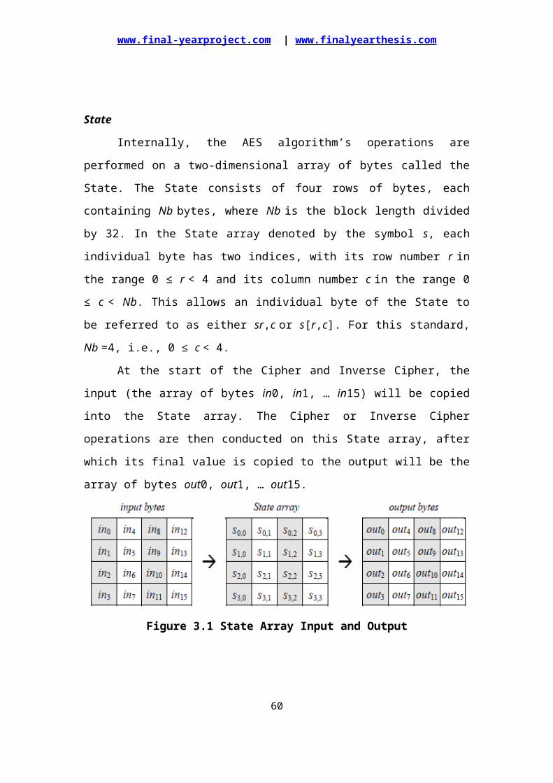
www.final-yearproject.com | www.finalyearthesis.com
-- ============================---- 4.4 MAIN ENTITY FOR AES ALGORITHM(USING 128 BITS KEY).---- THIS PROJECT REQUIRES THE FOLLOWING FILES:--- 1:AES_128.VHD(MAIN ENTITY)-- 2:AES_ROUND_128.VHD-- 3:AES_LAST_ROUND_128.VHD-- 4:AES_PACK_128.VHD-- 5:TEST_AES_128.VHD(TEST BENCH)-- ============================================================================== --library ieee;use ieee.std_logic_1164.all;use ieee.std_logic_unsigned.all;use work.AES_PACK_128.all;
entity AES_128 isport(DATA_OUT : out std_logic_vector(0 to 127); -- OUTPUT DATA --DOUT_VALID : out std_logic; -- PIN FOR VALID OUTPUT --KEY : in std_logic_vector(0 to 127); -- 128 BIT KEY --DATA_IN : in std_logic_vector(0 to 127); -- INPUT DATA --K_EN : in std_logic; -- KEY VALID --DIN_VALID : in std_logic; -- SELECTS ENCRYPTION OR DECRYPTION --ENC_DEC : in std_logic; -- VALID DATA --CE : in std_logic; -- CHIP ENABLE --CLK : in std_logic; -- CLOCK --RESET : in std_logic); -- RESET --end AES_128;
architecture BEHAV of AES_128 is
constant ZERO_STATE : STATE_TYPE :=(others=>(others=>(others=>'0')));
signal KEY_IN : std_logic_vector(0 to 127);-- FOLLOWING SIGNALS ARE FOR OUTPUT OF INDIVIDUAL ROUNDS --signal ROUND_00 : STATE_TYPE;signal ROUND_01 : STATE_TYPE;signal ROUND_02 : STATE_TYPE;signal ROUND_03 : STATE_TYPE;signal ROUND_04 : STATE_TYPE;signal ROUND_05 : STATE_TYPE;
60
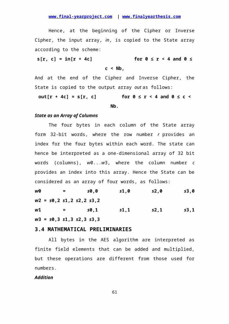
www.final-yearproject.com | www.finalyearthesis.com
signal ROUND_06 : STATE_TYPE;signal ROUND_07 : STATE_TYPE;signal ROUND_08 : STATE_TYPE;signal ROUND_09 : STATE_TYPE;signal DOUT_LST : STATE_TYPE;-- FOLLOWING SIGNALS ARE FOR KEYS OF INDIVIDUAL ROUNDS --signal KEY_00 : STATE_TYPE;signal KEY_01 : STATE_TYPE;signal KEY_02 : STATE_TYPE;signal KEY_03 : STATE_TYPE;signal KEY_04 : STATE_TYPE;signal KEY_05 : STATE_TYPE;signal KEY_06 : STATE_TYPE;signal KEY_07 : STATE_TYPE;signal KEY_08 : STATE_TYPE;signal KEY_09 : STATE_TYPE;signal KEY_LST : STATE_TYPE;-- FOLLOWING SIGNALS ARE USED AS DOUT VALID OF INDIVIDUAL ROUNDS --signal DOUT_VALID_00 : std_logic;signal DOUT_VALID_01 : std_logic;signal DOUT_VALID_02 : std_logic;signal DOUT_VALID_03 : std_logic;signal DOUT_VALID_04 : std_logic;signal DOUT_VALID_05 : std_logic;signal DOUT_VALID_06 : std_logic;signal DOUT_VALID_07 : std_logic;signal DOUT_VALID_08 : std_logic;signal DOUT_VALID_09 : std_logic;
signal EXP_KEY : EXP_KEY_TYPE;constant NK : integer := 4; -- NUMBER OF COLUMNS --
component AES_ROUND_128 -- COMPONENT DECLARATION FOR AES_ROUND --port (OUTPUT : out STATE_TYPE;DOUT_VALID: out std_logic;INPUT : in STATE_TYPE;ROUND_KEY : in STATE_TYPE;DIN_VALID : in std_logic;ENC_DEC : in std_logic;CLK : in std_logic;RESET : in std_logic);end component;
component AES_LAST_ROUND_128 -- COMPONENT DECLARATION FOR AES_LAST_ROUND --port (OUTPUT : out STATE_TYPE;DOUT_VALID: out std_logic;INPUT : in STATE_TYPE;ROUND_KEY : in STATE_TYPE;DIN_VALID : in std_logic;ENC_DEC : in std_logic;CLK : in std_logic;RESET : in std_logic);end component;
begin
61
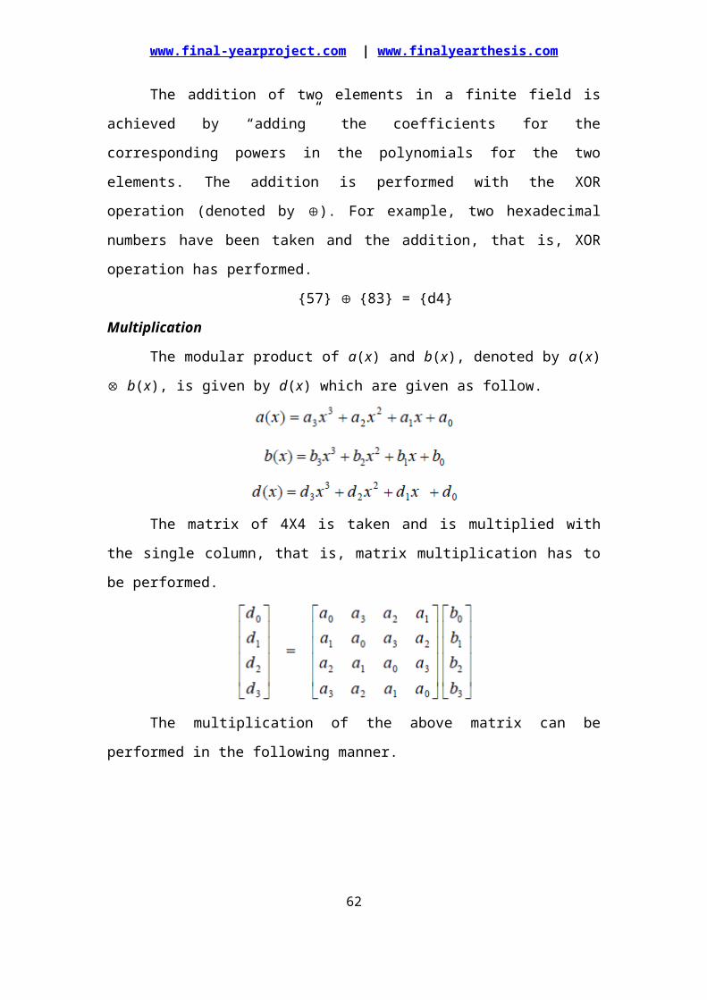
www.final-yearproject.com | www.finalyearthesis.com
-- THE FOLLOWING ARE THE NINE INSTANTIATIONS FOR AES_ROUND(i.e from a01 to a09) --a01: AES_ROUND_128port map(OUTPUT=>ROUND_01,DOUT_VALID=>DOUT_VALID_01,INPUT=>ROUND_00,ROUND_KEY=>KEY_01,DIN_VALID=>DOUT_VALID_00,ENC_DEC=>ENC_DEC,CLK=>CLK,RESET=>RESET);
a02: AES_ROUND_128port map(OUTPUT=>ROUND_02,DOUT_VALID=>DOUT_VALID_02,INPUT=>ROUND_01,ROUND_KEY=>KEY_02,DIN_VALID=>DOUT_VALID_01,ENC_DEC=>ENC_DEC,CLK=>CLK,RESET=>RESET);
a03: AES_ROUND_128port map(OUTPUT=>ROUND_03,DOUT_VALID=>DOUT_VALID_03,INPUT=>ROUND_02,ROUND_KEY=>KEY_03,DIN_VALID=>DOUT_VALID_02,ENC_DEC=>ENC_DEC,CLK=>CLK,RESET=>RESET);
a04: AES_ROUND_128port map(OUTPUT=>ROUND_04,DOUT_VALID=>DOUT_VALID_04,INPUT=>ROUND_03,ROUND_KEY=>KEY_04,DIN_VALID=>DOUT_VALID_03,ENC_DEC=>ENC_DEC,CLK=>CLK,RESET=>RESET);
a05: AES_ROUND_128port map(OUTPUT=>ROUND_05,DOUT_VALID=>DOUT_VALID_05,INPUT=>ROUND_04,ROUND_KEY=>KEY_05,DIN_VALID=>DOUT_VALID_04,ENC_DEC=>ENC_DEC,CLK=>CLK,RESET=>RESET);
a06: AES_ROUND_128port map(OUTPUT=>ROUND_06,DOUT_VALID=>DOUT_VALID_06,INPUT=>ROUND_05,ROUND_KEY=>KEY_06,
62
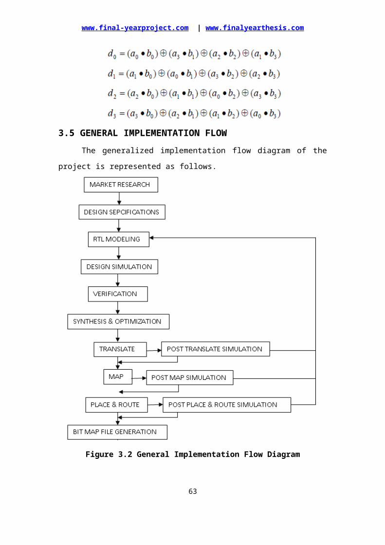
www.final-yearproject.com | www.finalyearthesis.com
DIN_VALID=>DOUT_VALID_05,ENC_DEC=>ENC_DEC,CLK=>CLK,RESET=>RESET);
a07: AES_ROUND_128port map(OUTPUT=>ROUND_07,DOUT_VALID=>DOUT_VALID_07,INPUT=>ROUND_06,ROUND_KEY=>KEY_07,DIN_VALID=>DOUT_VALID_06,ENC_DEC=>ENC_DEC,CLK=>CLK,RESET=>RESET);
a08: AES_ROUND_128port map(OUTPUT=>ROUND_08,DOUT_VALID=>DOUT_VALID_08,INPUT=>ROUND_07,ROUND_KEY=>KEY_08,DIN_VALID=>DOUT_VALID_07,ENC_DEC=>ENC_DEC,CLK=>CLK,RESET=>RESET);
a09: AES_ROUND_128port map(OUTPUT=>ROUND_09,DOUT_VALID=>DOUT_VALID_09,INPUT=>ROUND_08,ROUND_KEY=>KEY_09,DIN_VALID=>DOUT_VALID_08,ENC_DEC=>ENC_DEC,CLK=>CLK,RESET=>RESET);-- THIS LAST INSTANTIATION IS FOR AES_LAST_ROUND --alast: AES_LAST_ROUND_128port map(OUTPUT=>DOUT_LST,DOUT_VALID=>DOUT_VALID,INPUT=>ROUND_09,ROUND_KEY=>KEY_LST,DIN_VALID=>DOUT_VALID_09,ENC_DEC=>ENC_DEC,CLK=>CLK,RESET=>RESET);
EXP_KEY <= KEY_EXP(BITS2KEY(KEY_IN),NK,ENC_DEC);-- FOLLOWING STATEMENTS ARE USED FOR CALCULATING INDIVIDUAL ROUND KEYS --KEY_00 <= WORD2STATE(EXP_KEY,0);KEY_01 <= WORD2STATE(EXP_KEY,1);KEY_02 <= WORD2STATE(EXP_KEY,2);KEY_03 <= WORD2STATE(EXP_KEY,3);KEY_04 <= WORD2STATE(EXP_KEY,4);KEY_05 <= WORD2STATE(EXP_KEY,5);KEY_06 <= WORD2STATE(EXP_KEY,6);KEY_07 <= WORD2STATE(EXP_KEY,7);KEY_08 <= WORD2STATE(EXP_KEY,8);
63
www.final-yearproject.com | www.finalyearthesis.com
KEY_09 <= WORD2STATE(EXP_KEY,9);KEY_LST <= WORD2STATE(EXP_KEY,10);
DATA_OUT <= STATE2BITS(DOUT_LST);
initial_round:process(CLK,RESET)variable DATA : STATE_TYPE;beginif (RESET ='1') thenROUND_00 <= ZERO_STATE;KEY_IN <= (others=>'0');DOUT_VALID_00 <= '0';DATA := (others =>(others=> (others=>'0')));elsif (CLK'event and CLK='1') thenif(K_EN = '1' and CE = '1') thenKEY_IN <= KEY;elsif (DIN_VALID = '1' and CE = '1') thenDATA := BITS2STATE(DATA_IN(0 to 127));for i in 0 to NB-1 loopfor j in 0 to NB-1 loopROUND_00(i,j) <= DATA(i,j) xor KEY_00(i,j);end loop;end loop;DOUT_VALID_00 <= DIN_VALID;end if;end if;end process initial_round;
end BEHAV;--################################################################################--
64
www.final-yearproject.com | www.finalyearthesis.com
4.5 ENTITY FOR TESTING AES ENCRYPTION / DECRYPTION ROUND ***--library ieee;use ieee.std_logic_1164.all;use ieee.std_logic_unsigned.all;use work.AES_PACK_128.all;
entity TEST_AES_NEW_128 isend TEST_AES_NEW_128;
architecture BEHAV of TEST_AES_NEW_128 issignal DATA_OUT_0,DATA_OUT_1 : std_logic_vector(0 to 127);signal DOUT_VALID_0,DOUT_VALID_1 : std_logic;signal KEY : std_logic_vector(0 to 127);signal DATA_IN : std_logic_vector(0 to 127);signal K_EN : std_logic;signal DIN_VALID : std_logic;signal ENC_DEC : std_logic;signal CE : std_logic;signal CLK : std_logic:='0';signal RESET : std_logic;
component AES_128port(DATA_OUT : out std_logic_vector(0 to 127);DOUT_VALID : out std_logic;KEY : in std_logic_vector(0 to 127);DATA_IN : in std_logic_vector(0 to 127);K_EN : in std_logic;DIN_VALID : in std_logic;ENC_DEC : in std_logic;CE : in std_logic;CLK : in std_logic;RESET : in std_logic);end component;
begina0 : AES_128port map(DATA_OUT => DATA_OUT_0,DOUT_VALID => DOUT_VALID_0,KEY => KEY,DATA_IN => DATA_IN,K_EN => K_EN,DIN_VALID => DIN_VALID,ENC_DEC => ENC_DEC,CE => CE,CLK => CLK,RESET => RESET );
a1 : AES_128port map(DATA_OUT => DATA_OUT_1,DOUT_VALID => DOUT_VALID_1,KEY => KEY,DATA_IN => DATA_OUT_0,
65
www.final-yearproject.com | www.finalyearthesis.com
K_EN => K_EN,DIN_VALID => DOUT_VALID_0,ENC_DEC => '0',CE => CE,CLK => CLK,RESET => RESET );
CLK <= not CLK after 5 ns;
processvariable KEY_IN_B : bit_vector(0 to 127);variable DATA_IN_B : bit_vector(0 to 127);beginRESET<='1';KEY <=(others=>'0');K_EN <='0';DIN_VALID <='0';ENC_DEC <='1';CE <='1';wait for 10 ns;RESET <='0';KEY <=(X"2b7e151628aed2a6abf7158809cf4f3c"); -- First Set of InputsDATA_IN <=(X"3243f6a8885a308d313198a2e0370734");DIN_VALID <='1';K_EN <='1';ENC_DEC <='1';CE <='1';wait for 10 ns;K_EN <='0';wait for 230 ns;RESET<='1';KEY <=(others=>'0');K_EN <='0';DIN_VALID <='0';ENC_DEC <='1';CE <='1';wait for 10 ns;RESET <='0';KEY <=(X"000102030405060708090a0b0c0d0e0f"); -- Second Set of InputsDATA_IN <=(X"00112233445566778899aabbccddeeff");DIN_VALID <='1';K_EN <='1';ENC_DEC <='1';CE <='1';wait for 10 ns;K_EN <='0';wait for 230 ns;RESET<='1';KEY <=(others=>'0');DATA_IN <=(others=>'0');K_EN <='0';DIN_VALID <='0';ENC_DEC <='1';CE <='1';wait for 100 ns; -- Run the design for 500 ns
66
www.final-yearproject.com | www.finalyearthesis.com
end process;end BEHAV;
67
www.final-yearproject.com | www.finalyearthesis.com
RESULTS AND DISCUSSIONRESULTS AND DISCUSSION
5.1 INTRODUCTIONThe AES Encryption and Decryption algorithm and the implementation were
discussed in the previous chapters. Now this chapter deals with the simulation and
synthesis results of the implemented AES algorithm. Here Modelsim tool is used in
order to simulate the design and checks the functionality of the design. Once the
functional verification is done, the design will be taken to the Xilinx tool for
Synthesis process and the netlist generation.
The Appropriate test cases have been identified in order to test this modeled
AES Encryption and Decryption algorithm. Based on the identified values as the
reference the plain text and the key of 128 bits will be given as the input to the design
and the obtained cipher text should match the reference result. This proves that the
modeled design works properly as per the algorithm.
5.2 SIMULATION RESULTSThe test bench is developed in order to test the modeled design. This
developed test bench will automatically force the inputs, which were taken from the
reference, and will make the operations of algorithm to perform. The simulated
waveforms for the various cases have been discussed in this section.
CASE-1:
68
www.final-yearproject.com | www.finalyearthesis.com
Figure 5.1 Simulation Result of AES Encryption and Decryption for Set-1 Inputs
This case deals with the both encryption and decryption for first set of plain
text and a key of 128 bits. The basic and common inputs for both encryption and
decryption stage were clock (clk), chip enable (ce) and reset (rst). The reset signal is
active high, that is, when the reset signal is set to high, the system will be in reset state
and hence all the values will be ‘0’. Once the reset signal is set to low, the system will
start its process.
There is signal “enc_dec” which represents that the system is in which
operation either in encryption or decryption. When this “enc_dec” is set to high, the
encryption process will be carried out with the given inputs and when this signal is set
to low, the decryption process will be carried out. The two inputs named as “data_in”
and “key_in” which takes the given plain text and the key.
Encryption
Here the first sets of inputs are taken from the reference as follows.
Input = 32 43 f6 a8 88 5a 30 8d 31 31 98 a2 e0 37 07 34
Cipher Key = 2b 7e 15 16 28 ae d2 a6 ab f7 15 88 09 cf 4f 3c
The above inputs were represented in the hexadecimal format which contains
16 bytes, that is, 128 bits. So when the proper inputs were given as the input to the
system, “din_valid” and “k_en” signals will go high. These signals represents that the
valid data and the proper key is given to the system. Hence the output of the
69

www.final-yearproject.com | www.finalyearthesis.com
encryption process, that is, the cipher text for the given set of inputs is obtained as
follows.
Cipher Text = 39 25 84 1d 02 dc 09 fb dc 11 85 97 19 6a 0b 32
Decryption
The above cipher text, that is, encrypted data will be given as the input to the
decryption stage and the same key should be provided.
Input = 39 25 84 1d 02 dc 09 fb dc 11 85 97 19 6a 0b 32
Cipher Key = 2b 7e 15 16 28 ae d2 a6 ab f7 15 88 09 cf 4f 3c
Here the “din_valid” signal will goes high only after the encryption process.
Hence the decryption process will be carried out and the final output, that is, the same
plain text which is given as the input to the encryption stage will be achieved.
Final Output = 32 43 f6 a8 88 5a 30 8d 31 31 98 a2 e0 37 07 34
Thus the simulation result which is shown in the figure 4.1 gives the clear
view on the AES operation which was explained above.
CASE-2:
In this case, the same operation as the case-1 will be carried out with other
different sets of inputs. Here also both encryption and decryption process were clearly
represented in the simulation waveform shown in the figure 5.2.
Figure 5.2 Simulation Result of AES Encryption and Decryption for Set-2 Inputs
Here the inputs such as plain text and the key for the encryption process were
given as follows.
70
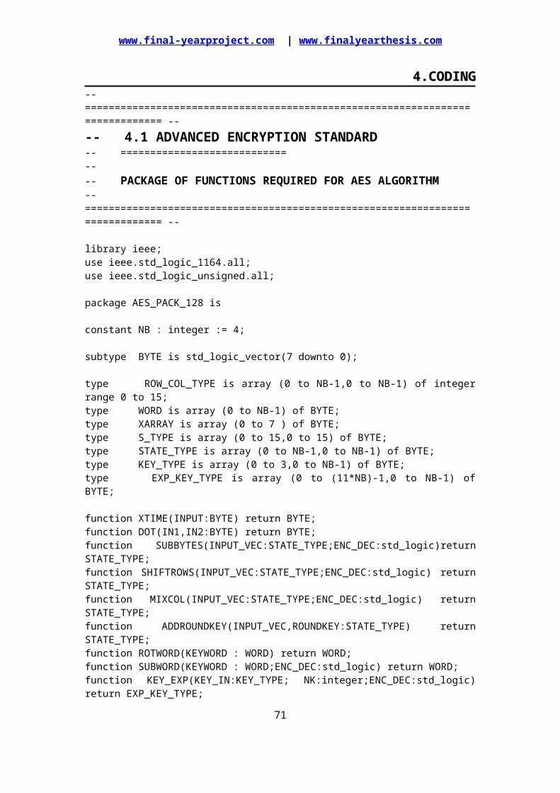
www.final-yearproject.com | www.finalyearthesis.com
Plain Text = 00 11 22 33 44 55 66 77 88 99 aa bb cc dd ee ff
Key = 00 01 02 03 04 05 06 07 08 09 0a 0b 0c 0d 0e 0f
The signals shown in the waveform were represents the same operation as
explained in the case-1. Hence the plain text and key were given as inputs to the
encryption stage and the cipher text will be obtained as output which is represented as
follows.
Cipher Text = 69 c4 e0 d8 6a 7b 04 30 d8 cd b7 80 70 b4 c5 5a
The above encrypted data in turn will be given as the input to the decryption
stage with the same key which produces the as plain text as the final output.
Final Output = 00 11 22 33 44 55 66 77 88 99 aa bb cc dd ee ff
Hence this represents that the developed AES Encryption and Decryption
Algorithm works with different set of inputs.
CASE-3:
This case deals with the internal operation of the AES Encryption process and
its results at each stage which has been clearly represented in the simulation
waveform shown in the figure 5.3.
Figure 5.3 Simulation Result of Encryption with Internal Operation for Set-1
Inputs
71
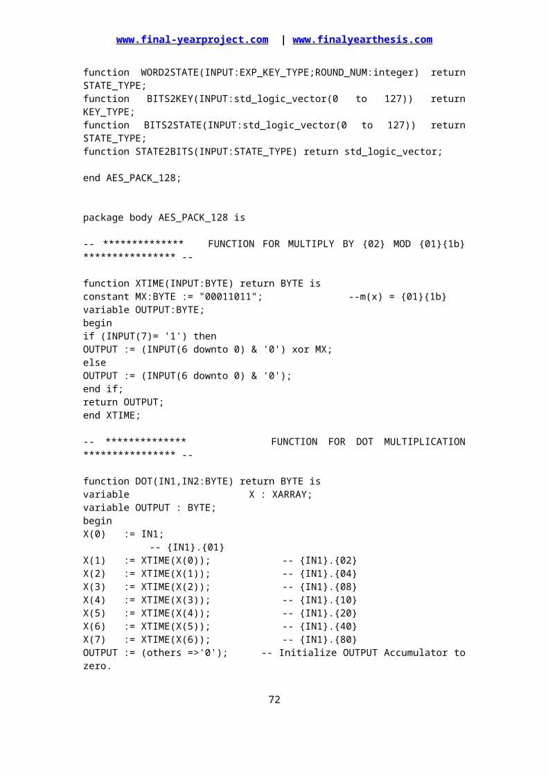
www.final-yearproject.com | www.finalyearthesis.com
The AES Encryption algorithm internally performs the operation such as
substitution, shifting and mixing of columns. As discussed in the previous chapter, the
operation of each process will be carried out and hence the output calculated values
will be seen clearly in the above waveform. So each round, all the internal operations
will be carried out and finally the MixColumn value and the key input of each round
will be XORed. Hence the output of the round will be taken as the input for the next
round. In above waveform, all the internal operation of round-1 and round-2 were
shown. Similarly for all the rounds, the same operations will be carried out with the
evaluated values. Hence at the last round, that is, round-10 the final values will be
evaluated and the cipher text will be given out.
CASE-4:
The internal operations involved during the decryption side were clearly
shown in the figure 5.4. The cipher text generated from encryption will be given as
input to the decryption block and the same kind of operation as in the encryption
process will be carried out with the different pre-defined values. In the waveform
round-1 and round-2 were shown in which its internal operation and their results are
shown clearly. The key will be given as the inverse of the generated one from the
encryption process.
72
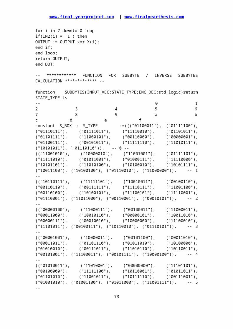
www.final-yearproject.com | www.finalyearthesis.com
Figure 5.4 Simulation Result of Decryption with Internal Operation for Set-1
Inputs
Finally the last round without MixColumn operation will be carried out in
order to produce the final output, that is, plain text.
CASE-5:
This case deals with the internal operations involved in the both encryption
and decryption with other set of inputs. The operation as explained in the case-3 and
case-4 were same as here, the only difference is that the input set is modified. Here we
are checking the operations are carried out properly with different inputs and the
obtained outputs were matches with the reference values.
Hence the figure 4.5 shows the internal operation of the AES Encryption
process and the figure 4.6 shows that the internal operations carried out in the AES
Decryption process. The waveform clearly represents the output values of the each
stage which were fed as input to the next process.
73
www.final-yearproject.com | www.finalyearthesis.com
Figure 5.5 Simulation Result of Encryption with Internal Operation for Set-2
Inputs
74
www.final-yearproject.com | www.finalyearthesis.com
Figure 5.6 Simulation Result of Decryption with Internal Operation for Set-2
Inputs
CASE-6:
In this case, the first set of inputs is taken and the whole 10 rounds have been
carried out.
Figure 5.7 Simulation Result of Encryption for Set-1 Inputs
Figure 4.7 clearly represents all the rounds and inputs and outputs of each
round. Thus the data at the every round output will be acting as the input to the next
round. These values can be cross verified with the reference values.
75
www.final-yearproject.com | www.finalyearthesis.com
Figure 5.8 Simulation Result of Decryption for Set-1 Inputs
Case-7:
In this case, the inputs and outputs of each round for the other set of inputs
were clearly represented in the figure 4.9 and figure 4.10 for the both encryption and
decryption process.
76
www.final-yearproject.com | www.finalyearthesis.com
Figure 5.9 Simulation Result of Encryption for Set-2 Inputs
Figure 5.10 Simulation Result of Decryption for Set-2 Inputs
Thus the simulation result of the AES algorithm for both encryption and
decryption were discussed above in different cases.
5.3 INTRODUCTION TO FPGAFPGA stands for Field Programmable Gate Array which has the array of logic
module, I /O module and routing tracks (programmable interconnect). FPGA can be
configured by end user to implement specific circuitry. Speed is up to 100 MHz but at
present speed is in GHz.
Main applications are DSP, FPGA based computers, logic emulation, ASIC
and ASSP. FPGA can be programmed mainly on SRAM (Static Random Access
Memory). It is Volatile and main advantage of using SRAM programming technology
is re-configurability. Issues in FPGA technology are complexity of logic element,
clock support, IO support and interconnections (Routing).
In this work, design of an AES Encryption and Decryption Algorithm is made
using VHDL is synthesized on FPGA family through XILINX ISE Tool. This process
includes following:
Translate
Map77
www.final-yearproject.com | www.finalyearthesis.com
Place and Route
5.3.1 FPGA FLOW
The basic implementation of design on FPGA has the following steps.
Design Entry
Logic Optimization
Technology Mapping
Placement
Routing
Programming Unit
Configured FPGA
Above shows the basic steps involved in implementation. The initial design
entry of may be VHDL, schematic or Boolean expression. The optimization of the
Boolean expression will be carried out by considering area or speed.
Figure 5.11 Logic Block
In technology mapping, the transformation of optimized Boolean expression to
FPGA logic blocks, that is said to be as Slices. Here area and delay optimization will
be taken place. During placement the algorithms are used to place each block in
FPGA array. Assigning the FPGA wire segments, which are programmable, to
establish connections among FPGA blocks through routing. The configuration of final
chip is made in programming unit.
5.4 SYNTHESIS RESULT
78
www.final-yearproject.com | www.finalyearthesis.com
The developed AES Encryption and Decryption Algorithm are simulated and
verified their functionality. Once the functional verification is done, the RTL model is
taken to the synthesis process using the Xilinx ISE tool. In synthesis process, the RTL
model will be converted to the gate level netlist mapped to a specific technology
library. This AES algorithm design can be implemented on FPGA (Field
Programmable Gate Array) family of Virtex-2. Here in this Virtex-2 family, many
different devices were available in the Xilinx ISE tool. In order to implement this
AES design the device named as “XC2V8000” has been chosen and the package as
“FF1517” with the device speed as “-5”.
The design of AES Encryption and Decryption Algorithm is synthesized and
its results are analyzed as follows.
RTL Schematic
The RTL (Register Transfer Logic) can be viewed as black box after
synthesize of design is made. It shows the inputs and outputs of the system. By
double-clicking on the diagram we can see gates, flip-flops and MUX.
Figure 5.12 RTL Schematic
The above figure 5.12 shows the top level block diagram that contains the
primary inputs and outputs of the design.
Device utilization summary:
This device utilization includes the following.
Logic Utilization
79
INPUT S
OUTPUT S

www.final-yearproject.com | www.finalyearthesis.com
Logic Distribution
Total Gate count for the Design
The device utilization summery is shown above in which its gives the details
of number of devices used from the available devices and also represented in %.
Hence as the result of the synthesis process, the device utilization in the used device
and package is shown above.
Timing Summary:
Speed Grade: -5
Minimum period: 52.716ns (Maximum Frequency: 18.970MHz)
Minimum input arrival time before clock: 20.103ns
Maximum output required time after clock: 4.840ns
Maximum combinational path delay: No path found
In timing summery, details regarding time period and frequency is shown are
approximate while synthesize. After place and routing is over, we get the exact timing
summery. Hence the maximum operating frequency of this synthesized design is
given as 18.970 MHz and the minimum period as 52.719 ns. OFFSET IN is the
80
www.final-yearproject.com | www.finalyearthesis.com
minimum input arrival time before clock and OFFSET OUT is maximum output
required time after clock.
5.5 SUMMARY The developed AES algorithm is modeled and is simulated using the
Modelsim tool.
The simulation results are discussed by considering different cases.
The RTL model is implemented using the Xilinx tool in Virtex-2 and their
synthesis results are discussed with the help of generated reports.
81

www.final-yearproject.com | www.finalyearthesis.com
CONCLUSION AND FUTURE SCOPECONCLUSION AND FUTURE SCOPE
6.1 CONCLUSIONFirstly, understanding the concept of cryptology and flow of AES algorithm is
done. Successful implementation of AES algorithm, make to know one of the
encryption and decryption standard available in market and it helps to explore the
path to implement such an algorithm using VHDL. Mainly, the concept of
instantiation and arrays plays a major part in implementation. This is a 128-bit Key
dependent algorithm which has control over the 128-bit input data or plaintext. The
original message is taken to 10 round operations which produces the ciphertext. This
resultant encrypted data is fed as the input to the decryption and 10 rounds operations
were carried out and hence the same plain text is achieved. Given the same input key
and data (plaintext or ciphertext) any implementation that produces the same output
(ciphertext or plaintext) as the algorithm specified in this standard is an acceptable
implementation of the AES.
The simulation results have been verified for the different appropriate test
cases. Finally the developed model is taken to the Xilinx tool and done the
implementation using the FPGA family of Virtex-2 board.
6.2 FUTURE SCOPEIn recent days, AES (Advanced Encryption Standard) is used which has
increased level of security. This work on the AES Encryption and Decryption
Algorithm of 128 bits can be extended in the future in the following ways.
As this algorithm supports the key length of 192 bits and 256 bits, the work
can be extended by increasing the key length which increases both the security
level to high and also the difficulties in hacking level.
Also this work can be extended by developing a switch. This switch will be
used to switch the system of key lengths to either of 128 bits, 192 bits and 256
bits. This will be handling all the three key lengths and the required process
can be carried out by with respect to the switch.
82
www.final-yearproject.com | www.finalyearthesis.com
APPENDIX-1APPENDIX-1 STANDARD TABLES FOR AES ALGORITHM
Key-Block-Round Combinations
S-Box: Substitution Values used in Encryption Process
Matrix Value used in MixColumn Operation in Encryption Process
83
www.final-yearproject.com | www.finalyearthesis.com
S-Box: Substitution Values used in Decryption Process
Matrix Value used in MixColumn Operation in Decryption Process
84
www.final-yearproject.com | www.finalyearthesis.com
7.BIBILOGRAPHY
1.AES page available via http://www.nist.gov/CryptoToolkit.
2.Computer Security Objects Register (CSOR): http://csrc.nist.gov/csor/.
3.B.Gladman’s AES related home page http://fp.gladman.plus.com/cryptography.technology/.
85