· web viewcurriculum – 2014 (c-14) diploma in electronics & communication. engineering. 1...
TRANSCRIPT
1
CURRICULUM –
2014 (C-14)
DIPLOMA IN ELECTRONICS & COMMUNICATION
ENGINEERING
1
State Board of Technical Education & Training Telangana State
HYDERABAD
D:\B
acku
p\S
BTE
T_C
14\D
EC
E -
1st P
roof
- 1

2 3
CONTENTS III SEMESTER
S.No Subject Code Subject Page No
S.No Content Page No
I PREAMBLE 5 1 EC -301 Engineering Mathematics – II 137
II RULES AND REGULATIONS 8 2 EC -302 Electronic Devices & Circuits 142
1. Admission Procedures 8 3 EC -303 Electronic Measuring Instruments 152
2. Scheme of Examination 10 4 EC -304 Analogue Communication 158
3. Rules of Promotion to Next Level 13 5 EC -305 Digital Electronics 165
4. Students Performance Evaluation 18 6 EC -306 Electrical Technology 172
5. Issue of Certificates and Veto 22 7 EC -307 Electronic Devices & Circuits Laboratory Practice 180
8 EC -308 Analogue Communication Lab practice 191
III SYLLABUS 9 EC -309 Digital Electronics & eCAD tools Laboratory Practice200
10 EC -310 Electrical Technology Laboratory Practice 211
I YEAR
S.No Subject Code Subject Page No
1 EC-101 English 31 IV SEMESTER
2 S.No Subject Code Subject Page No2 EC -102 Engineering Mathematics – I 34
3 EC -103 Engineering Physics 47 1 EC -401 Engineering Mathematics – III 220
4 EC -104 Engineering Chemistry & Environmental Studies 57 2 EC -402 Linear Integrated Circuits 227
5 EC -105 Basic Electrical and Electronics Engineering 67 3 EC -403 Network Analysis 236
6 EC -106 Electronic Engineering Materials & Practices 84 4 EC -404 Digital Communications 243
7 EC -107 Engineering Drawing 94 5 EC -405 Microprocessor & Microcontroller Programming 249
8 EC -108 Basic Electronic Workshop Practice 102 6 EC -406 Programming in C 256
9 EC -109 Physics Lab Practice 118 7 EC -407 Linear Integrated Circuits Lab Practice 261
10 EC -110 Chemistry Lab Practice 123 8 EC -408 Communication Skills Lab Practice 271
11 EC -111 Computer Fundamentals Lab Practice 127 9 EC -409 Digital Communication Lab Practice 274
10 EC -410 C and Matlab Practice 281
D:\B
acku
p\S
BTE
T_C
14\D
EC
E -
1st P
roof
- 2

4 5
V SEMESTER
S.No Subject Code Subject Page No
1 EC -501 Industrial Management 293
2 EC -502 Consumer Electronics 299
3 EC -503 Industrial Electronics 306
4 EC -504 Microcontroller Applications 312
5 EC -505 Electronic Product Design & Quality Assurance 318
6 EC -506 Mobile Communications 323
7 EC -507 Industrial Electronics Lab Practice 329
8 EC -508 Life Skills 339
9 EC -509 Microcontroller Applications Lab Practice 350
10 EC -510 Field Practices 359
VI SEMESTER
S.No Subject Code Subject Page No
1 EC -601 Advanced Communication Systems 3693
2 EC -602 Data communication & Computer Networking 374
3 EC -603 Optical Fibre Communication 380
4 EC -604 Computer Hardware 386
5 EC -605 Advanced Microcontrollers & DSP 391
6 EC -606 Digital Circuit Design through Verilog HDL 397
7 EC -607 Computer HW, Networking & OFC Lab Practice 403
8 EC -608 Verilog HDL Programming Lab Practice 413
9 EC -609 Advanced Microcontroller Lab Practice 418
10 EC -610 Project Work 422
CURRICULUM ( C-14 )FOR DIPLOMA COURSES IN Telangana
I. PREAMBLEThe State Board of Technical Education and Training, Telangana under
the aegis of the Department of Technical Education, Telangana generally reviews the Curricula once in every five years. However, recognizing the changing needs as stated by the user industries, the Board has decided to bring forward the revision of curriculum. Consequently, the Board with the assistance of NITTTR, Chennai under the guidance of Prof. C. Nagendra Rao, performed the evaluation of C-09 Curriculum in force. On finding the merits and demerits of C-09 Curriculum the faculty have made a thorough assessment of the curricular changes that have to be brought in. It was felt that there is an urgent need to improve hands-on experience among the students pursuing diploma courses. Further, the urgency of enhancing communication skills in English was also highlighted in the feedback and suggestions made by the user industries. Keeping these in view, a number of meetings and deliberations were held at district and state level, with experts from industry, academia and senior faculty of the department. The new Curricula for the different diploma courses have been designed with the active participation of the members of the faculty teaching in the Polytechnics of Telangana, besides reviewed by Expert Committee constituted with eminent academicians.
The primary objective of the curricular change is to produce best technicians in the country by correlating growing needs of the industries with the academic input.
The revised New Curriculum i.e., Curriculum – 2014 or C-14 is vetted by NITTTR, Chennai followed by BoG approval of SBTET for its implementation with effect from 2014-15.
Salient Features:
.
1. Duration of course is either 3 years / 3½ years duration of Regular Academic Instruction.
2. The Curriculum is prepared in Semester Pattern. However, First Year is maintained as Year-wise pattern.
3. The policy decisions taken at the State and Central level with regard to environmental science are implemented by including relevant topics in
D:\B
acku
p\S
BTE
T_C
14\D
EC
E -
1st P
roof
- 3

6 7
Chemistry. This is also in accordance with the Supreme Court guidelines issued in Sri Mehta’s case.
4. Keeping in view the increased need of communication skills which is playing a major role in the success of Diploma Level students in the Industries, emphasis is given for learning and acquiring listening, speaking, reading and writing skills in English. Further as emphasized in the meetings, Communication Skills lab and Life Skills lab are introduced in IV and V semesters respectively for all the branches except Chemical Engineering and Chemical Engineering (Sugar Technology) for which life skills is introduced at 3rd semester level..
5. In addition to Engineering Mathematics in I year (Mathematics -102) and III semester (Mathematics-301), Mathematics-401 has been introduced in the IV semester of present syllabus.
6. Modern topics relevant to the needs of the industry and global scenario suitable to be taught at Diploma level are also incorporated in the curriculum.
7. CAD specific to the branch has been given more emphasis in the curriculum. Preparing drawings using CAD software has been given more importance.
8. Every student is exposed to the computer lab at the 1st year itself in order to familiarize himself with skills required for keyboard/mouse operation,internet usage and e-mailing. 4
9. The number of teaching hours allotted to a particular topic/chapter has been rationalized keeping in view the past experience
10. Upon reviewing the existing C-09 curriculum, it is found that the theory content is found to have more weightage than the Practical content. In the revised C-14 curriculum, more emphasis is given to the practical content of Laboratories and Workshops, thus strengthening the practical skills.
11. With increased emphasis for the student to acquire Practical skills, the course content in all the subjects is thoroughly reviewed and structured as outcome based than the conventional procedure based. While the course content in certain subjects is reduced, in rest of the subjects the content has been enhanced as per the need.
12. A new subject “Field Practices” is introduced in 5th Semester. In Field Practices, the students will perform all the industry oriented activities for all types of Field tastings and make use of the machinery, equipment and tools actually used in the industry. By this, the student will get first-
hand experience of performing various practical procedures and field experiments to enhance their skills.
13. All Practical subjects are independent of each other and the practice of grouping two or more practical subjects is dispensed with.
14. Curricular of Laboratory and Workshops have been thoroughly revised based on the suggestions received from the industry and faculty, for better utilization of the equipment available at the Polytechnics. The experiments /exercises that are chosen for the practical sessions are identified to conform to the field requirements of industry.
15. The Members of the working group are grateful to Sri Ajay Jain, I.A.S., Commissioner of Technical Education & Chairman, S.B.T.E.T. and Smt.Sailaja Ramaiyer, I.A.S., for their guidance and valuable inputs in revising, modifying and updating the curriculum.
16. The Members acknowledge with thanks the cooperation and guidance provided by the Sri. D. Venkateswarlu, Secretary, SBTET, Telangana and Dr. CN Rao, Professor and Head, NITTTR, ECH and other officials of Directorate of Technical Education and the State Board of Technical Education, Telangana, experts from industry, academia from the universities and higher learning institutions and all teaching fraternity from the Polytechnics who are directly and indirectly involved in preparation of the curricula.
D:\B
acku
p\S
BTE
T_C
14\D
EC
E -
1st P
roof
- 4

8 9
II. RULES AND REGULATIONS
1. ADMISSION PROCEDURES :
DURATION AND PATTERN OF THE COURSES
All the Diploma programs run at various institutions are of AICTE approved 3 years or 3½ years duration of Academic Instruction.
All the Diploma courses are run on year wise pattern in the First year, and the remaining two or two & half years are run in the semester pattern. In respect of few courses like Diploma in Electronics with specialization in CP/ CN/ IE/ TV/ BM/ Embedded systems, the training will be in the seventh semester.
PROCEDURE FOR ADMISSION INTO THE DIPLOMA COURSES:
Selection of candidates is governed by the Rules and regulations laid down in this regard from time to time.
i) Candidates who wish to seek admission in any of the Diploma courses will have to appear for Common Entrance Test for admissions into Polytechnics (POLYCET) conducted by the State Board of Technical Education and Training, Telangana, Hyderabad.
Only the candidates satisfying the following requirements will be eligible 5to appear for the Common Entrance Test for admissions into Polytechnics(POLYCET).
a) The candidates seeking admission should have appeared for the X class examination, conducted by the Board of Secondary Examination, Telangana or equivalent examination thereto, at the time of making application to the Common Entrance Test for Polytechnics for admissions into Polytechnics (POLYCET). In case of candidates who apply pending results of their qualifying examinations, their selection shall be subject to production of proof of their passing the qualifying examination in one attempt or compartmentally at the time of interview for admission.
b) Admissions are made based on the merit obtained in the Common Entrance Test (POLYCET) and the reservation rules stipulated by the Government of Telangana from time to time.
c) For admission into the following Diploma Courses for which entry qualification is 10+2, candidates need not appear for POLYCET. A separate notification will be issued for admission into these courses.
1). D.H.M.C.T. 2). D.Pharmacy
MEDIUM OF INSTRUCTION
The medium of instruction and examination shall be English.
PERMANENT IDENTIFICATION NUMBER (PIN)
A cumulative / academic record is to be maintained of the Marks secured in sessional work and end examination of each year for determining the eligibility for promotion etc., a Permanent Identification Number (PIN) will be allotted to each candidate so as to facilitate this work and avoid errors in tabulation of results.
NUMBER OF WORKING DAYS PER SEMESTER / YEAR:
a). The Academic year for all the Courses usually shall be from Fifteenth June of the year of admission to the 31st March of the succeeding year.
b). The Working days in a week shall be from Monday to Saturday
c). There shall be 7 periods of 50 minutes duration on all working days. d).
The minimum number of working days for each semester / year shall be90 / 180 days excluding examination days. If this prescribed minimum is not achieved due to any reason, special arrangements shall be made to conduct classes to cover the syllabus.
ELIGIBILITY OF ATTENDANCE TO APPEAR FOR THE END EXAMINATION
a). A candidate shall be permitted to appear for the end examination in all subjects, if he or she has attended a minimum of 75% of working days during the year/Semester.
b). Condonation of shortage of attendance in aggregate upto 10% (65% and above and below 75%) in each semester or 1st year may be granted on medical grounds.
c). Candidates having less than 65% attendance shall be detained.
d). Students whose shortage of attendance is not condoned in any semester/ 1st year are not eligible to take their end examination of that class and their admissions shall stand cancelled. They may seek re-admission for that semester / 1st year when offered next.
e). A stipulated fee shall be payable towards condonation for shortage of attendance.
D:\B
acku
p\S
BTE
T_C
14\D
EC
E -
1st P
roof
- 5
10 11
READMISSION
Readmission shall be granted to eligible candidates by the respective RJD / Principal.
1) Within 15 days after commencement of class work in any semester (Except industrial Training).
2) Within 30 days after commencement of class work in any year (includingD. Pharmacy course or first year course in Engineering and Non Engineering Diploma streams).
Otherwise such cases shall not be considered for readmission for that semester / year and are advised to seek readmission in the next subsequent eligible academic year.
The percentage of attendance of the readmitted candidates shall be calculated from the first day of begining of the regular class work for that year / Semester, as officially announced by CTE/SBTET but not form the day on which he/she has actually reported to the class work, after readmission is granted.
2. SCHEME OF EXAMINATION
a) First Year
THEORY EXAMINATION: Each Subject carries 80% marks with examination of 3 hours duration, along with 20% marks for internal 6evaluation. (Sessional marks). However, there are no minimum marks prescribed for sessionals.
PRACTICAL EXAMINATION: There shall be 40% Marks for regular practical work done, i.e. sessional marks for each practical subject with an end examination of 3 hours duration carrying 60% marks. However, there are no minimum marks prescribed for sessionals.
b) III, IV, V and VI Semesters:
THEORY EXAMINATION: Each subject carries usually 80 marks and 40 marks in respect of specified subjects of 3hours duration, along with 20/ 10 marks for internal evaluation (sessional marks) respectively.
PRACTICAL EXAMINATION: Each subject carry 30/60 marks of 3hours duration 20/40 sessional marks.
INTERNAL ASSESSMENT SCHEME
a) Theory Subjects: Theory Subjects carry 20 % sessional marks, Internal examinations will be conducted for awarding sessional marks on the dates specified. Three unit tests will be conducted for I year students
and two Unit Tests for semesters. Average of marks obtained in all the prescribed tests will be considered for awarding the sessional marks.
b) Practicals: Student’s performance in Laboratories / Workshop shall be assessed during the year of study for 40% marks in each practical subject. Allotment of marks should be discrete taking into consideration of the students skills, accuracy, recording and performance of the task assigned to him / her. Each student has to write a record / log book for assessment purpose. In the subject of Drawing, which is also considered as a practical paper, the same rules hold good. Drawing exercises are to be filed in seriatum.
c) Internal assessment in Labs / workshops / Survey field etc., during the course of study shall be done and sessional marks shall be awarded by the concerned Lecturer / Senior Lecturer / Workshop superintendent as the case may be.
d) For practical examinations, except in drawing, there shall be two examiners. External examiner shall be appointed by the Principal in consultation with respective head of the department preferably choosing a person from an Industry. Internal examiner shall be the person concerned with internal assessment as in (c) above. The end examination shall be held along with all theory papers in respect of drawing.
e) Question Paper for Practicals: Question paper should cover all the experiments / exercise prescribed.
f) Records pertaining to internal assessment marks of both theory and practical subjects are to be maintained for official inspection.
g) In case of Diploma courses having Industrial Training, the training assessment shall be done and marks be awarded in the following manner.
Industrial assessment : 200 marks (in two spells of 100 marks each)
Maintenance of log book : 30 marks
Record Work : 30 marks
Seminar / viva-voce : 40 marks
———————
TOTAL : 300 marks
———————-
The assessment at the institute level will be done by a minimum of three members Internal Faculty, Industrial Experts and H.O.D. and be averaged.
D:\B
acku
p\S
BTE
T_C
14\D
EC
E -
1st P
roof
- 6

12 13
h) In case of Diploma courses not having Industrial Training in the curriculum, the students shall make Industrial visits as per the schedule given below:
S.No Semester Nature ofTraining/Exposure Duration
1 III Semester Industrial Visits 5 no. (One week)2 IV Semester Industrial Visits 5 no. (One week)
3End of Semester
Vacation of IVSemester
Industrial Training 4 Weeks
4 V SemesterIndustrial Visits 5 no. (one Week)
Simulated IndustrialTraining (Field Practices) 3 Weeks
5 VI Semester Industrial Visits 5 no. (one Week)Total 11 Weeks
NOTE: No Marks shall be awarded for the above industrial visits. However, it will be evaluated as satisfactory/unsatisfactory.
MINIMUM PASS MARKS
THEORY EXAMINATION:
For passing a theory subject, a candidate has to secure a minimum of 35% in end examination and a combined minimum of 35% of both Sessional and end examination marks put together.
7PRACTICAL EXAMINATION:
For passing a practical subject, a candidate has to secure, a minimum of 50% in end examination and a combined minimum of 50% of both sessional and practical examination marks put together. In case of D.C.C.P., the pass mark for typewriting and short hand is 45% in the end examination. There are no sessional marks for typewriting and Shorthand subjects of D.C.C.P course.
PROVISION FOR IMPROVEMENT
1. Improvement is allowed only after he / she has completed all the subjects from First Year to Final semester of the Diploma.
2. Improvement is allowed in any 4 (Four) subjects of the Diploma.
3. The student can avail of this improvement chance only once, that too within the succeeding two examinations after the completion of Diploma, with the condition that the duration including Improvement examination shall not exceed FIVE years from the first admission.
4. No improvement is allowed in Practical / Lab subjects or Project work or Industrial Training assessment. However, improvement is allowed in drawing subject.
5. If improvement is not achieved, the marks obtained in previous Examinations hold good.
6. Improvement is not allowed in respect of the candidates who are punished under Mal-practice in any Examination.
7. Examination fee for improvement shall be paid as per the notification issued by State Board of Technical Education and Training from time to time.
8. All the candidates who wish to appear for improvement of performance shall deposit the original Marks Memos of all the years / Semesters and also original Diploma Certificate to the Board. If there is improvement in performance of the current examination, the revised Memorandum of marks and Original Diploma Certificate will be issued else the submitted originals will be returned.
3 RULES OF PROMOTION TO NEXT LEVEL :
For Diploma Courses (Except HMCT, Architecture, Chemical-Sugar & Auto mobile Engineering) From 1ST YEAR TO 3,rd, 4,th 5th , 6th and 7th Semesters:
1. A candidate shall be permitted to appear for first year examination provided he / she puts in 75% attendance and pays the examination fee. However, he/she can be condoned on Medical grounds upto 10% ( i.e. attendance after condonation on Medical grounds should not be less than 65%) and he/she has to pay the condonation fee along with examination fee.
2. A candidate shall be promoted to 3rd semester if he/she puts the required percentage of attendance in the first year and pays the examination fee. A candidate who could not pay the first year examination fee has to pay the promotion fee as prescribed by State Board of Technical Education and Training from time to time before commencement of 3rd semester.
3. A candidate shall be promoted to 4th semester provided he/she puts the required percentage of attendance in the 3rd semester and pays the examination fee. A candidate who could not pay the 3rd semester exam fee, has to pay the promotion fee as prescribed by State Board of Technical Education and Training from time to time before commencement of 4th semester.
A candidate is eligible to appear for the 4th semester exam if he/she
D:\B
acku
p\S
BTE
T_C
14\D
EC
E -
1st P
roof
- 7

14 15
i) Puts the required percentage of attendance in the 4th semester
ii) Should not have failed in more than Four backlog subjects of 1st year
4. A candidate shall be promoted to 5th semester provided he / she puts the required percentage of attendance in the 4th semester and pays the examination fee on fulfilment of 3(i)(ii) clauses stated above. A candidate, who could not pay the 4th semester examination fee, has to pay the promotion fee as prescribed by State Board of Technical Education and Training from time to time before commencement of 5th semester.
A candidate is eligible to appear for the 5th semester exam if he/she
i) Puts the required percentage of attendance in the5 th semester
ii) Should have obtained eligibility to appear for 4th Semester examination.
For IVC students.
i) Puts the required percentage of attendance in the5th semester
ii) Should have appeared for 4th Semester examination.
iii) Should not have failed in more than Four backlog subjects of III Semester
5. A candidate shall be promoted to 6th semester provided he/she has puts the required
percentage of attendance in the 5th semester and pay the examination 8fee, a candidate who could not pay the 5th semester examination fee,has to pay the promotion fee as prescribed by State Board of Technical Education and Training from time to time before commencement of 6 th
semester.
A candidate is eligible to appear for 6th semester examination if he/she
i) Puts the required percentage of attendance in 6th semester and
ii) Should not have failed in more than six backlogs subjects of 1st year, 3rd
& 4th semesters put together.
For IVC students.
i) Puts the required percentage of attendance in the6th semester
ii) Should have obtained eligibility to appear for V semester examination.
iii) Should not have failed in more than Six backlog subjects of III & IV Semester put together.
For HMCT, Architecture and Chemical - Sugar courses
1) The same rules are applicable on par with other diploma courses with the exception that the Industrial Training is in the 5th semester.
2) A candidate shall be promoted to 5th semester (Industrial Training) provided he/she puts the required percentage of attendance in the 4 th
semester and pay the examination fee. A candidate, who could not pay the 4th semester examination fee, has to pay the promotion fee as prescribed by the SBTET from time to time before commencement of 5th
semester (Industrial Training).
3) A candidate shall be promoted to 6th semester of the course provided he/ she has successfully completed the Industrial Training (Passed).
A candidate is eligible to appear for the 6th semester examination if he/ she
(i) Puts the required percentage of attendance in 6th semester.
(ii) Should not have failed in more than six backlog subjects of 1st Year, 3rd & 4th
semesters put together.
For IVC students
i) Puts the required percentage of attendance in the6th semester
ii) Should have completed the Industrial Training.
iii) Should not have failed in more than Six backlog subjects of III & IV
Semester put together.
Automobile Engineering Course
The same rules are applicable on par with other diploma courses with the exception that the Industrial Training is in the 6th semester.A Candidate shall be promoted to 6th semester provided he/she puts the required percentage of attendance in 5th semester and pay the examination fee. A candidate, who could not pay the 5th semester examination fee, has to pay the promotion fee prescribed by SBTET from time to time before commencement of 6th semester (Industrial Training).
Or
The Automobile Engineering Industrial Training may be shifted to 5th
semester on par with HMCT/ARCH/CH (ST)
D:\B
acku
p\S
BTE
T_C
14\D
EC
E -
1st P
roof
- 8

16 17
For Diploma Courses of 3 ½ Years duration:
MET/ CH/ CHPP/ CHPC/ CHOT/ TT
1. A candidate shall be permitted to appear for 1st year examination provided he / she puts in 75% attendance (which can be condoned on Medical grounds upto 10%) i.e. attendance after condonation on Medical grounds should not be less than 65% and pay the examination fee.
2. A candidate shall be promoted to 3rd semester if he/she puts the required percentage of attendance in the 1st year and pays the examination fee. A candidate who could not pay the 1st year examination fee has to pay the promotion fee as prescribed by State Board of Technical Education and Training from time to time before commencement of 3rd semester.
3. A candidate shall be promoted to 4th semester provided he/she puts the required percentage of attendance in the 3rd semester and pay the examination fee. A candidate, who could not pay the 3 rd semester exam fee, has to pay the promotion fee as prescribed by State Board of Technical Education and Training from time to time before commencement of 4th semester.
A candidate is eligible to appear for the 4th semester exam if he/she
i) Puts the required percentage of attendance in the 4th semester
ii) Should not have failed in more than Four backlog subjects of 1 s t year. 9
4. A candidate shall be promoted to 5th semester provided he / she puts the required percentage of attendance in the 4th semester and pays the examination fee. A candidate, who could not pay the 4th semester examination fee, has to pay the promotion fee as prescribed by State Board of Technical Education and Training from time to time before commencement of 5th semester.
5. Promotion from 5th to 6th semester is automatic (i.e., from 1st spell of Industrial Training to 2nd spell) provided he/she puts the required percentage of attendance, which in this case would be 90 % attendance and attends for the VIVA-VOCE examination at the end of training.
6. A candidate shall be promoted to 7th semester of the course provided he/she has successfully completed both the spells of Industrial Training (Passed).
A candidate is eligible to appear for 7th semester examination if he/she
i) Puts the required percentage of attendance in the 7th semester and
ii) Should not have failed in more than 6 backlog subjects of 1st year,3rd and 4th semesters put together.
iii) Should not have failed in more than six backlog subjects of 3rd and 4th semester put together for IVC students.
For Diploma Courses of 3 ½ Years duration:
FW
i) In respect of Diploma in Footwear Technology, the Industrial training is offered in two spells, the 1st spell of Industrial training after the First Year (i.e. III semester of the course) and the second spell of industrial training after the V semester (i.e VI Semester of the course). The promotion rules for this course are on par with the other sandwich Diploma courses except that there is no restriction on number of backlog subjects to get eligibility to appear for the 4th semester examination and ,
A candidate is eligible to appear for 5th semester examination if he/she
1. Puts the required percentage of attendance in the 5th semester and
2. Should not have failed in more than four subjects of 1st year.
ii) A candidate shall be promoted to 7th semester of the course provided he/ she has successfully completed second spell of Industrial Training (Passed).
A candidate is eligible to appear for 7th semester examination if he/she
1. Puts the required percentage of attendance in the 7th semester and
2. Should not have failed in more than 6 backlog subjects of 1st year and 4th
semesters put together.
3. Should not have failed in more than six backlog subjects of 4th and 5th
semester
put together for IVC students.
For Diploma Courses of 3 ½ Years duration:
BM
The same rules as are applicable for conventional courses also apply for these courses. Since the industrial training in respect of these courses is restricted to one semester (6 months) after the 6th semester (3 years) of the course.
A candidate shall be promoted to 7th semester provided he/she puts the required percentage of attendance in 6th semester and pay the examination fee. A candidate, who could not pay the 6th semester examination fee, has to pay the promotion fee prescribed by SBTET
D:\B
acku
p\S
BTE
T_C
14\D
EC
E -
1st P
roof
- 9

18 19
from time to time before commencement of the 7 th semester (Industrial Training).
OR
Run through system for 1st Year and 3rd semester to 6/7th semester provided that the student puts in 75% of attendance (which can be condoned on medical grounds upto 10%) i.e. attendance after condonation on medical grounds should not be less than 65%.
OTHER DETAILS
a) In case a candidate does not successfully complete the Industrial training, he / she will have to repeat the training at his / her own cost.
b) The I spell of Industrial training shall commence 10 days after the completion of the last theory examination of 4th Semester.
c) The Second spell of Industrial training shall commence within 10 days after the completion of I spell of Industrial training.
d) Each Semester of Institutional study shall be a minimum of 90 working days. (With 6 working days in a week i.e. from Monday to Saturday, with 7 periods of 50 minutes, duration per day.
4 STUDENTS PERFORMANCE EVALUATION
AWARD OF DIPLOMA
Successful candidates shall be awarded the Diploma under the following divisions of pass.
1. First Class with Distinction shall be awarded to the candidates who secure an overall aggregate of 75% marks and above.
2. First Class shall be awarded to candidates who secure overall aggregate of 60% marks and above and below 75% marks.
3. Second Class shall be awarded to candidates who secure a pass with an overall aggregate of below 60%.
The Weightage of marks for various year/Semesters which are taken for computing overall aggregate shall be 25% of I year marks + 100% of 3rd
and subsequent Semesters.
With respect to the intermediate vocational candidates who are admitted directly into diploma course at the 3rd semester (i.e., second year) level the aggregate of (100%) marks secured at the 3rd and subsequent semesters of study shall alone be taken into consideration for
determining the overall percentage of marks secured by the candidates for award of class/division.
4. Second Class shall be awarded to all students, who fail to complete the Diploma in the regular three years and four subsequent examinations, from the first admission.
EXAMINATION FEE SCHEDULE:
The examination fee should be paid as per the notification issued by State Board of Technical Education and Training from time to time.
STRUCTURE OF END EXAMINATION QUESTION PAPER:
The question paper for theory examination is patterned in such a manner that the Weightage of periods/marks allotted for each of the topics for a particular subject be considered.
Examination paper is of 3/6/9 hour’s duration.
a) Each theory paper consists of Section ‘A’ and Section ‘B’. Section ‘A’ contains 10 short answer questions. All questions are to be answered and each carries 3 marks Max. Marks: 10 x 3 = 30.
Section B contains 8 essay type questions including Numerical
10 questions, out of which 5 questions each carrying 10 marks are to be answered.
Max.Marks: 5 x 10 = 50.
Total Maximum Marks: 80.
b) For Engineering Drawing Subject (107) consist of section ‘A’ and section ‘B’. Section ‘A’ contains four (4) questions. All questions in section ‘A’ are to be answered and each carries 5 marks. Max. Marks: 4 x 5=20. Section ‘B’ contains six (6) questions. Out of which four (4) questions to be answered and each question carries 10 Marks. Max. Marks 4 x 10 = 40.
Practical Examinations
For Workshop practice and Laboratory Examinations,
Each student has to pick up a question paper distributed by Lottery System.
Max. Marks for an experiment / exercise : 50%
Max. Marks for VIVA-VOCE : 10%
Total : 60%
D:\B
acku
p\S
BTE
T_C
14\D
EC
E -
1st P
roof
- 10
20 21
In case of practical examinations with 50 marks, the marks will be worked out basing on the above ratio.
In case of any change in the pattern of question paper, the same shall be informed sufficiently in advance to the candidates.
ISSUE OF MEMORONDUM OF MARKS
All candidates who appear for the end examination will be issued memorandum of marks without any payment of fee. However candidates who lose the original memorandum of marks have to pay the prescribed fee to the Secretary, State Board of Technical Education and Training, Telangana. for each duplicate memo.
MAXIMUM PERIOD FOR COMPLETION OF DIPLOMA COURSES:
Maximum period for completion of the course is twice the duration of the course from the date of First admission (includes the period of detention and discontinuation of studies by student etc) failing which they will have to forfeit the claim for qualifying for the award of Diploma (They will not be permitted to appear for examinations after that date). This rule applies for all Diploma courses of 3 years and 3 ½ years of engineering and non-engineering courses.
ELIGIBILITY FOR AWARD OF DIPLOMA
A candidate is eligible for award of Diploma Certificate if he / she fulfils the following academic regulations.
i. He / She pursued a course of study for not less than 3 / 3 ½ academic years & not more than 6 / 7 academic years.
ii. He / she has completed all the subjects.
Students who fail to fulfill all the academic requirements for the award of the Diploma within 6 / 7 academic years from the year of admission shall forfeit their seat in the course & their seat shall stand cancelled.
RECOUNTING, ISSUE OF PHOTO COPY OF VALUED ANSWER SCRIPT & REVERIFICATION:
a) A candidate desirous of applying for Recounting/ issue of Photo copy of valued answer scripts/ Reverification should submit the application to the Secretary, State Board of Technical Education and Training, Telangana., Hyderabad – 500 063 within 15 days from the date
of receipt of Tabulated Marks Statement by the Principal of concerned Polytechnic or the date specified.
Recounting shall be done for any TWO theory subjects per Year/Semester only, including drawing subjects. No request for recounting shall be entertained from any candidate who is reported to have resorted to Malpractice in that examination. The fee prescribed for Recounting should be paid by way of Demand Draft drawn on any Scheduled Bank payable at Hyderabad in favour of the Secretary, State Board of Technical Education and Training, Telangana., Hyderabad. The verification of the totaling will be done by an Officer of the Board and will be intimated to the candidate by post only.
The following documents should be invariably be enclosed with the application failing which the application will not be considered.
1. Marks secured as per Tabulated Marks Sheet certified by the Principal.
2. Demand draft towards the payment of fee
3. Self – addressed and stamped envelopes of 11" X 5" size.
The applications received after the prescribed date will not be accepted and any correspondence in this regard will not be entertained.
FOR ISSUE OF PHOTO COPIES OF VALUED ANSWER SCRIPTS
11 1. A candidate desirous of applying for Photo copy of valued answer script/ scripts should submit the application to the Secretary, State Board of Technical Education and Training, Telangana., Hyderabad – 500 063 along with the required fee in the form of Demand Draft within 07 days from the date of receipt of Tabulated Marks Statement by the Principal of concerned Polytechnic or the date specified in the covering letter whichever is earlier.
2. Photo copies of valued answer scripts will be issued to all theory subjects including drawing subjects.
3. The following documents should invariably be enclosed with the application
(1) Marks secured as per Tabulated Marks Sheets certified by the Principal
(2) Self-addressed Stamped Envelope/Cloth-line cover of size 10’’ x 14’’.
(3) Fee in the form of Demand Draft
FOR RE-VERIFICATION OF THE VALUED ANSWER SCRIPT
D:\B
acku
p\S
BTE
T_C
14\D
EC
E -
1st P
roof
- 11
22 23
1. A candidate desirous of applying for Re-verification of valued answer script should submit the application to the Secretary, State Board of Technical Education and Training, Telangana., Hyderabad – 500 063 along with the required fee in the form of Demand Draft, within 15 days from declaration of result.
2. Re-verification of valued answer script shall be done for all theory subjects including drawing subjects.
3. The following documents should invariably be enclosed with the application failing which the application will not be considered.
(i) Marks secured as per Tabulated Marks Sheets certified by the Principal.
(ii) Fee in the form of Demand Draft.
MALPRACTICE CASES:
If any candidate resorts to any Mal Practice during examinations, he / she shall be booked and the Punishment shall be awarded as per rules and regulations framed by SBTET from time to time.
DISCREPANCIES/ PLEAS:
Any Discrepancy /Pleas regarding results etc., shall be represented to the Board within one month from the date of issue of results. Thereafter, no such cases shall be entertained in any manner.
5 ISSUE OF CERTIFICATES AND VETO
ISSUE OF DUPLICATE DIPLOMA
If a candidate loses his/her original Diploma Certificate and desires a duplicate to be issued he/she should produce written evidence to this effect. He / she may obtain a duplicate from the Secretary, State Board of Technical Education and Training, Telangana on payment of prescribed fee and on production of an affidavit signed before a First Class Magistrate (Judicial) and non-traceable certificate from the Department of Police. In case of damage of original Diploma Certificate, he / she may obtain a duplicate certificate by surrendering the original damaged certificate on payment of prescribed fee to the State Board of Technical Education and Training.
In case the candidate cannot collect the original Diploma within 1 year from the date of issue of the certificate, the candidate has to pay the penalty prescribed by the SBTET from time to time.
ISSUE OF MIGRATION CERTIFICATE AND TRANSCRIPTS:
The Board on payment of prescribed fee will issue these certificates for the candidates who intend to prosecute Higher Studies in India or Abroad.
GENERAL
i. The Board may change or amend the academic rules and regulations or syllabi at any time and the changes or amendments made shall be applicable to all the students, for whom it is intended, with effect from the dates notified by the competent authority.
ii. All legal matters pertaining to the State Board of Technical Education and Training are within the jurisdiction of Hyderabad.
iii. In case of any ambiguity in the interpretation of the above rules, the decision of the Secretary, SBTET is final.
12
D:\B
acku
p\S
BTE
T_C
14\D
EC
E -
1st P
roof
- 12

290 291
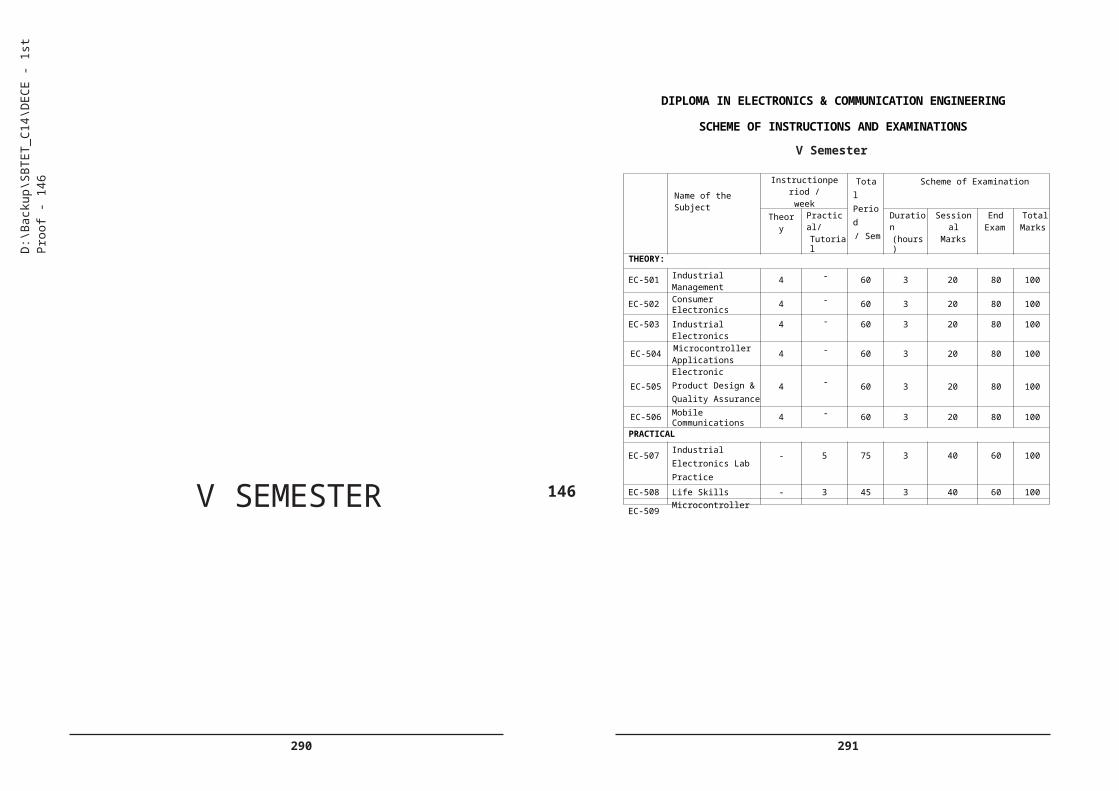
DIPLOMA IN ELECTRONICS & COMMUNICATION ENGINEERING
SCHEME OF INSTRUCTIONS AND EXAMINATIONS
V Semester
V SEMESTER
146
D:\B
acku
p\S
BTE
T_C
14\D
EC
E -
1st P
roof
- 14
6
Name of the SubjectInstructionperiod /
weekTotal
Period/ Sem
Scheme of Examination
Theory Practical/Tutorial
Duration(hours)
SessionalMarks
EndExam
TotalMarks
THEORY:
EC-501 Industrial Management
4 - 60 3 20 80 100
EC-502 ConsumerElectronics 4 - 60 3 20 80 100
EC-503 Industrial Electronics 4 - 60 3 20 80 100
EC-504 MicrocontrollerApplications
4 - 60 3 20 80 100
EC-505Electronic Product Design & Quality Assurance
4 - 60 3 20 80 100
EC-506 MobileCommunications 4 - 60 3 20 80 100
PRACTICAL
EC-507Industrial Electronics Lab Practice
- 5 75 3 40 60 100
EC-508 Life Skills - 3 45 3 40 60 100
EC-509Microcontroller Applications labPractice
- 3 45 3 40 60 100
EC-510 Field Practices - 7 105 3 40 60 100
TOTAL 24 18 630 280 720 1000

292 293
Note:
1. Five no local industrial visits / Interaction, one from each of the courses listed from EC 502 to EC506 may be arranged to enable the students to have industry exposure.
2. Duration: one week
3.. The students need to submit 2-3 page write up mentioning all salient learning experiences like advance intechnology, its evaluation, application, advantages & disadvantages, expected changes in future etc.,
4. Three weeks of simulated industrial training (Field practices) to be conducted in the institution or in the field is included to enable the students to have field exposure.
147
INDUSTRIAL MANAGEMENT
Subject Title : INDUSTRIALMANAGEMENTSubject Code : EC-501Periods/Week : 04Periods/semester : 60
TIME SCHEDULESl.No. Major Topics Periods Weightage
of marksShort
questionsEssay
questions
1. Overview Of Business 4 6 2
2. Management Process 6 13 1 1
3. Organizational Management
6 13 1 1
4. Human Resource Management
12 23 1 2
5. Financial Management 10 16 2 1
6. Materials Management 8 13 1 1
7. Project Management 14 26 2 2
Total 60 110 10 8
OBJECTIVESUpon completion of the course the student shall be able to
Explain the basics of BusinessDefine Business
State the Types of Business ( Service, Manufacturing, Trade)
Explain the business procedures in Engineering sector ( Process industry, Textile industry, Chemical industry, Agro industry,)
State the need for Globalization.
D:\B
acku
p\S
BTE
T_C
14\D
EC
E -
1st P
roof
- 14
7
294 295
List the Advantages & Disadvantages of globalization w.r.t. India.
Explain the importance of Intellectual Property Rights (I.P.R.)
Explain the Management Process:Define Management.
Explain the concept of management
Explain the Different Levels of management
Explain Administration & management
State the principles of Scientific management by F.W.Taylor
State the principles of Management by Henry Fayol (14 principles)
List the Functions of Management
i) Planning
ii) Organizing
iii) Directing
iv) Controlling
Explain the four Functions of Management.
Appreciate the need for Organizational ManagementDefine Organization
List the Types of organization :a) Line b) Line & staff c) Functional d) Project
Explain the four types of organization.
Define departmentation.
Explain the following types of departmentations
i) Centralized & Decentralized
ii) Authority & Responsibility
iii) Span of Control
Explain the Forms of ownership
i)Proprietorship
ii) Partnership
iii) Joint stock
iv) Co-operative
Society v)Govt. Sector
148
Appreciate the need for Human Resource ManagementDefine Personal Management.
Explain the functions of Personal Management
Define Staffing .
State the importance of HR Planning.
Explain the various Recruitment Procedures.
Explain the need for Training & Development .
State the various types of training procedures( Induction, Skill Enhancement etc)
State the different types of Leaderships,
Explain the Maslow's Theory of Motivation
Explain the Causes of accident and the Safety precautions to be followed.
Explain the importance of various Acts - Factory Act, ESI Act, Workmen Compensation Act, Industrial Dispute Act etc.
Explain the basics of Financial ManagementState the Objectives of Financial Management.
State the Functions of Financial Management.
5.3. State the necessity of Capital Generation & Management.
List the types of Capitals.
List the Sources of raising Capital.
Explain the Types of Budgets
i) Production Budget (including Variance Report )
ii) Labour Budget.
Describe Profit & Loss Account ( only concepts) .
Describe the proforma of Balance Sheet.
Explain i) Excise Tax ,
ii) Service Tax
iii) Income Tax
iv) VAT
v) Custom Duty.
6.0 Explain the importance of Materials Management
D:\B
acku
p\S
BTE
T_C
14\D
EC
E -
1st P
roof
- 14
8

296 297
6.1. Define Inventory Management (No Numerical).
State the objectives of Inventory Management.
Explain ABC Analysis.
State Economic Order Quantity.
Describe the Graphical Representation of Economic Order Quantity.
State the objectives of Purchasing.
State the functions of Purchase Department.
Explain the steps involved in Purchasing.
State the Modern Techniques of Material Management.
Describe the JIT / SAP / ERP packages.
2.0 Management processConcept of management - levels of management - Scientific management- by FW Taylor - Principles of management- functions of management - Administration - management.
3.0 Organizational managementOrganization - types of organization( line, line & staff, staff & project) - Departmentation - Classification (centralized, decentralized, Authority,Responsibility, and span of co
ntrol - Forms of Ownership - Proprietorship - Partnership - Joint stock - Co-operative society and Government sectors.
Explain the importance of Project ManagementState the meaning of Project Management.
Describe the CPM & PERT Techniques of Project Management.
Identify the critical path and find the project duration.
Explain the concept of Break Even Analysis
Define Quality.
State the concept of Quality.
Describe the various Quality Management systems.
Explain the importance of Quality policy, Quality control, Quality Circle.
State the principles of Quality Assurance.
State the concepts of TQM , Kaizen 5's and 6 sigma.
State the constituents of ISO 9000 series standards.
Course contents :
1.0 Overview of Business:Business - types of business in various sectors- service, manufacturing & trade- Industrial sectors - Engineering, process, Textile, Chemical, Agro industries - Globalization and effect of globalization - advantages and Disadvantages- Intellectual Property Rights (I.P.R.)
149
4.0 Human Resource ManagementPersonal Management - Staffing - Introduction to HR planning - Recruitment procedures - Types of Trainings -Personal training - skill development training - Leaderships - types - Motivation - Maslows theory- Causes of accidents - safety precautions - Factory Act - Workmen compensation Act - Industrial disputes Act- ESI Act.
5.0 Financial ManagementIntroduction - Objectives of Financial Management - Types of capitals - sources of raising capital - Types of budgets - production budgets - labour budgets - Concept of Profit loss Account - Concept of balance sheet - proforma - types of taxes - brief concepts of - Excise Tax, Service Tax, Income Tax, VAT and custom duty.
6.0 Material ManagementInventory Management - objectives of Inventory Management - ABC Analysis - Economic order Quantity - Purchasing - Objectives of purchasing- Functions - Procedures - Material Management - JIT / SAP / ERP.
7.0 Project ManagementIntroduction - CPM & PERT - concept of Break event Analysis - quality system - Definition of Quality , concept of Quality , Quality policy, Quality control, Quality Circle, Quality Assurance, Introduction to TQM- Kaizen 5's and 6 sigma concepts, ISO 9000 series standards.
D:\B
acku
p\S
BTE
T_C
14\D
EC
E -
1st P
roof
- 14
9
298 299
REFERENCES1. Dr. O.P. Khanna - Industrial Engg &Management-Dhanpath Rai & sons
New Delhi
2. Dr. S.C. Saxena & W.H. Newman& E.Kirby Warren-Business Administration &Management -Sahitya Bhavan Agra
3. Andrew R. McGill -The process of Management-Prentice- Hall
4. Rustom S. Davar -Industrial Management-Khanna Publication
5. Banga & Sharma -Industrial Organization &Management -Khanna Publication
6. Jhamb & Bokil -Industrial Management -Everest Publication, Pune.
150
CONSUMER ELECTRONICS
Subject Title : CONSUMER ELECTRONICS
Subject Code : EC-502
Periods/Week : 04
Periods/Semester : 60
Rationale: Consumer Electronics Subject is introduced to meet the needs of consumer electronics Industry. The units in the course are designed to impart the concepts of Audio Video systems, Television, Cable TV, DTH services and other domestic appliances like Microwave ovens and Automatic washing Machines.
TIME SCHEDULE
Sl. Major Topics No. of periods
Weightage of marks
Short Answer Questions
Essay Questions
1 Microphones & Speakers 10 21 2 1 ½
2 Audio Systems 8 13 1 1
3 TV Picture & Composite Video Signal 16 23 1 2
4 Colour Television 8 21 2 1 ½
5 Cable, Satellite and digital TV 10 16 2 1
6 Domestic Appliances 8 16 2 1Total 60 110 10 8
OBJECTIVES
Upon completion of the course the student should be able to
Understand the working of Microphones and Speakers
Familiarise with different types of microphones and loud speakers
List the different types of microphones based on impedance, polar characteristics and principle of working.
Explain the working of carbon, condenser, Crystal, ribbon and dynamic microphones along with their polar characteristics.
D:\B
acku
p\S
BTE
T_C
14\D
EC
E -
1st P
roof
- 15
0

300 301
Compare the parameters like sensitivity, noise, frequency response, directivity, output impedance, bias necessity, size, cost and applications of above microphones.
List the ratings of condenser, crystal, carbon, ribbon and dynamic microphones.
Explain the constructional features and principle of operation of PMMC Loudspeaker and its ratings.
Mention the necessity of Baffle for a Loudspeaker
List the four types of Baffles (like open, infinite, bass reflex, acoustic labyrinth)
Explain the constructional details of above types of speakers.
Mention the use of woofers and tweeters.
Mention the need for a Horn loud speaker
Explain the construction of Horn loud speaker
List different types of Horn loud speakers.
Compare the performance characteristics of cone type and horn type loud speakers.
Explain the principle, construction and working of magnetic and crystal headphones
Explain the use of Headphones.
Mention the specifications of Loudspeaker and Microphones.
Understand Audio Systems
Define speech, music and noise.
Explain frequency response and equalization.
Define the concept of Hi-Fi and Stereo.
State the need of bass, treble, balance, and volume control in stereo amplifier.
Explain a simple circuit showing the above controls.
Explain the principle of magnetic recording and reproduction.
List five advantages and disadvantages magnetic recording.
State the principle of optical recording.
Explain the method of optical recording of sound on film
151
Explain the working principle of DVD player.
Explain the working of DVD player with block diagram.
Explain MP3 & MP4 formats.
Explain the concept of noise reduction using DOLBY system.
Explain home theatre sound system.
Explain the speaker arrangement and features of Dolby Digital 5.1 Surround Sound(AC3)
Comprehend TV Picture & Composite video signal
Explain formation of picture.
State the need for horizontal and vertical scanning.
State the frame and field frequencies.
State need for vertical synchronisation, horizontal synchronisation and blanking pulses.
Mention the frequency allocation of T.V. Channels used in India.
Mention Important standards of T.V. transmissions as per C.C.I.R.
List different types of scanning
Distinguish between progressive and interlaced scanning.
Draw the standard scanning pattern in an interlaced scanning.
State the need for interlaced scanning with reference to Bandwidth.
List all different pulses in a composite video signal.
State and compare positive and negative modulation.
Sketch composite video signal as per I.S.I. specification.
State the need for front porch and back porch in blanking pulses.
State the necessity of equalising pulses and serrated vertical blanking pulses.
Understand the working of Colour Television.
Explain the main characteristic of human eye with regard to perception of colours.
Distinguish between additive and subtractive mixing of colours.
D:\B
acku
p\S
BTE
T_C
14\D
EC
E -
1st P
roof
- 15
1

302 303
Explain complementary colours, hue, saturation, and Colour circle.
Explain compatibility in TV system.
List three standards of Colour transmission system NTSC, PAL and SECAM.
Explain how chrominance signals are transmitted on one carrier in PAL system.
Draw the block diagram of a Colour TV transmitter and state the function of each block.
Explain the processing of Colour video signal (PAL system) in a Colour receiver.
Mention different types (like Plasma ,LCD,LED,OLED) of Colour TV monitors
Explain the basic principles of above technologies
Understand the principles of Cable, Satellite and Smart TV
Draw and explain the block diagram of CATV.
Explain the cable TV components such as amplifiers directional couplers and Converters.
Explain the necessity of mid-band and super-band channels
State the need for satellite for TV broadcasting over wide area.
Explain the merits of DTH system
With a block diagram explain DVB-S channel reception with block diagram.
State the need for Set Top Box.
List main features of Projection TV
List applications of Projection TV
Explain the features of HDTV
Explain the features of SMART TV.
List the important specifications of UHD TV
Understand the working of Domestic Appliances
Explain the working principle of Microwave oven
152
Explain functional block diagram of Microwave oven
List 3 advantages of Microwave oven
Explain the principle of Induction heater.
Give the reasons for using magnetic metals for use with induction heater.
List the 4 merits of induction heating.
Explain the functional block diagram of Electronic Washing machine
List any three advantages of Fuzzy logic in washing machines
Explain functional block diagram of Camcorder
List the applications of Camcorder
COURSE CONTENT
1. Microphones and Speakers
Familiarise with different types of microphones and loud speakers- Different types of microphones based on impedance, polar characteristics and principle of working-Working of carbon, condenser, Crystal, ribbon and dynamic microphones along with their polar characteristics-Compare the parameters like sensitivity, noise, frequency response, directivity, output impedance, bias necessity, size, cost and applications of above microphones-Ratings of condenser, crystal, carbon, ribbon and dynamic microphones-Constructional features and principle of operation of PMMC Loudspeaker and its ratings- Necessity of Baffle for a Loudspeaker and types of Baffles (like open, infinite, bass reflex, acoustic labyrinth) and constructional details-Use of woofers and tweeters-Need for a Horn loud speaker with its construction and advantages. Types of horns-Performance characteristics of cone type and horn type loud speakers-Principle, construction and working of magnetic and crystal headphones and their uses-Specifications of Loudspeaker and Microphones.
2. Audio Systems: Speech, music and noise-Frequency response and equalization-Concept of Hi-Fi and Stereo-Need of bass, treble, balance, and volume control in stereo amplifier-Simple circuit showing the above controls-Principle of magnetic recording and reproduction-Advantages and disadvantages magnetic recording-Principle of optical recording- Method of optical recording of sound on film-Working principle of DVD player-Working of DVD player with block diagram-MP3 & MP4 formats- Concept of noise reduction using DOLBY system-Home theatre sound
D:\B
acku
p\S
BTE
T_C
14\D
EC
E -
1st P
roof
- 15
2
304 305
system-Speaker arrangement and features of Dolby Digital 5.1 Surround Sound (AC3).
3. TV Picture & Composite video signal:
Formation of picture-Need for horizontal and vertical scanning-Frame and field frequencies-Need for vertical synchronisation, horizontal synchronisation and blanking pulses-Frequency allocation of T.V. Channels used in India-Standards of T.V. transmissions as per C.C.I.R- Types of scanning-Distinguish between progressive and interlaced scanning-Standard scanning pattern in an interlaced scanning-Need for interlaced scanning with reference to Bandwidth-Different pulses in a composite video signal-Comparision of positive and negative modulation-Composite video signal as per I.S.I. specification-Need for front porch and back porch in blanking pulses-Necessity of equalising pulses and serrated vertical blanking pulses.
4. Colour Television.
Main characteristic of human eye with regard to perception of colours- Additive and subtractive mixing of colours-Complementary colours, hue, saturation, and Colour circle-Compatibility in TV system-Standards of Colour transmission system like NTSC, PAL and SECAM-Chrominance signals are transmitted on one carrier in PAL system-Block diagram of a Colour TV transmitter and state the function of each block-Block diagram of a Colour TV receiver and state the function of each block-Processing of Colour video signal (PAL system) in a Colour receiver-Types of Colour TV monitors-Basic principles of above technologies.
5. Principles of Cable, Satellite and Smart TV:
Block diagram of CATV-Cable TV components such as amplifiers directional couplers and Converters-Necessity of mid-band and super- band channels-Need for satellite for TV broadcasting over wide area- Merits of DTH system- DVB-S channel reception with block diagram- Need for SET TOP BOX-Features of Projection TV-Applications of Projection TV-Features of HDTV-Features of SMART TV-Important specifications of UHD TV.
6. Domestic Appliances:
Working principle of Microwave oven-Functional block diagram of Microwave oven-Advantages of Microwave oven-Principle of Induction
153
heater-Reasons for using magnetic metals for use with induction heater- Merits of induction heating-Functional block diagram of Electronic Washing machine-Advantages of Fuzzy logic in washing machines- Functional block diagram of Camcorder-Applications of Camcorder.
REFERENCE BOOKS:
1. Electronic communication systems by Roy Blake, Thomson Delmar.
2. Colour Television by R.R.Gulati. TMH
3. How electronic things work.& what to do when they don’t -Robert L. Goodman, -TMH
4. Consumer electronics by SP Bali, -Pearson publications.
5. Digital Satellite Television Handbook By Mark E. Long –Newnes publications
D:\B
acku
p\S
BTE
T_C
14\D
EC
E -
1st P
roof
- 15
3
306 307
INDUSTRIAL ELECTRONICS
Subject Title : Industrial Electronics
Subject Code : EC-503
Periods/Week : 04
Periods/Semester : 60
Rationale: Industrial Electronics subject is included in the VI semester to make the students understand the applications of Electronic principles they have learnt in the previous semesters. This course will no doubt, make the students feel confident to face the interviews and work in the field when they join the industries.
TIME SCHEDULE
Sl Major Topics No. of periods
Weightage of marks
Short Answer
QuestionsEssay
Questions1 Power Electronic Devices 16 26 2 22 Transducers & Ultrasonics 14 26 2 2
3 Industrial heating & Welding 10 21 2 1 ½
4 PLC & Programming 12 21 2 1 ½5 Control Engg 8 16 2 1
Total 60 110 10 8
OBJECTIVES
Upon completion of thiscourse a student should be able to
Understand the construction and working of Power Electronic Devices
List different thyristor family devices.
Sketch the circuit symbols for each device.
Explain constructional details of SCR.
Explain the working of SCR using two Transistor analogy.
Explain the Volt-Ampere characteristics of SCR.
Mention the important ratings of SCR.
154
Define forward break over voltage, latching current, holding current, turn on triggering time, turn off time of SCR.
Explain the construction of GTO SCR
Compare the characteristics of GTO SCR and SCR.
Distinguish between SUS, SBS, SCS & LASCR
Explain SCR circuit triggering by UJT with a circuit diagram.
Draw input and Output waveforms.
Mention the use of SCR in single phase and three phase Power rectifiers.
Explain the construction of Diac.
Explain the Volt-ampere characteristics of Diac
Explain the construction of Triac.
Explain the Volt-ampere characteristics of Triac.
Explain different modes of Triac triggering.
Explain the Phase control circuit using Diac and Triac for AC power control.
Draw the input and output waveforms.
Mention the differences between BJT and Power BJT.
Explain the working of Insulated gate Bipolar transistor (IGBT),
Explain the need for protection of power devices(snubber circuit).
Give important specifications of power electronic devices from Manufacturer’s data sheet .
List the six important applications of power electronic devices.
Explain the working of MOSFET based Inverter circuit.
With a block diagram explain the working of a) Off Line UPS b) Online UPS
Explain PWM Voltage control of UPS
Explain the limitations of series Voltage regulated power supplies
Explain the working of SMPS with block diagram
Mention any 3 applications of SMPS
Explain the working of Servo stabilizer
Understand the working of transducers and Ultrasonics
D:\B
acku
p\S
BTE
T_C
14\D
EC
E -
1st P
roof
- 15
4

308 309
Classify transducers on the basis of principle of operation and applications.
Explain the working principle, construction and applications of strain gauge.
Explain the working principle, construction and applications of potentiometric transducer.
Explain the working principle, construction of capacitive and inductive transducers.
Mention the 6 important applications of above transducers.
Explain the working principle, construction and applications of LVDT.
Explain the working principle and construction of Piezo electric transducer.
List any 3 uses of the Piezo electric transducer
Explain the working principle of RTD & Thermocouple transducer.
Mention the 6 important applications of above transducers.
Explain the application of transducer in Accelerometer, servomotors, and Tachogenerators.
Explain the term Ultrasonic.
Mention methods of generating ultrasonic waves.
Draw and explain pulsed-echo ultrasonic flaw detector
Explain the principle of MEMS devices
Mention their use in modern smart phones and other devices
Industrial Heating & welding
Classify industrial heating methods.
Explain the principle of induction heating.
List four applications of induction heating.
Draw the circuit of HF power source for induction heating and explain its working.
Explain the principle of dielectric heating.
Explain the electrodes used in dielectric heating & method of coupling to RF generator.
Mention the applications of dielectric heating.
155
Explain the use of statement list .
Explain control systems flow charts.
Write simple Ladder program using bit instructions Timer instructions and counter instructions
List types of PLCs.
List the features of popular PLCs like Siemens , Allenbradly .
List any 4 applications of PLCS in the industry.
Control Engineering
Define system and Control system.
Classify control systems
Explain the basic block diagram of control system
Explain an open loop control system.
Give examples for open loop control system.
Give three merits and demerits of open loop control.
Explain the closed loop system with the help of a block diagram.
Give Examples for closed loop system
Compare Open loop and closed loop control systems.
Define Transfer function
Explain the use of Laplace transforms in control systems
COURSE CONTENT
1. Power Electronic Devices - Different thyristor family devices- circuit symbols - Constructional details of SCR- Working of SCR using two Transistor analogy- Volt-Ampere characteristics of SCR- Ratings of SCR- forward break over voltage, latching current, holding current, turn on triggering time, turn off time of SCR- Construction of GTO SCR-Compare the characteristics of GTO SCR and SCR- Constructional details of Diac & Triac- Volt-ampere characteristics of Diac & Triac under forward/ Reverse bias- Different modes of Triac triggering- SUS, SBS, SCS & LASCR- SCR circuit triggering by UJT - input and Output waveforms- Use of SCR in single phase and three phase Power rectifiers- Construction of Diac- Volt-ampere characteristics of Diac - Construction
D:\B
acku
p\S
BTE
T_C
14\D
EC
E -
1st P
roof
- 15
5
310 311
of Triac- Volt-ampere characteristics of Triac- Different modes of Triac triggering- Phase control circuit using Diac and Triac for AC power control- input and output waveforms- Differences between BJT and Power BJT-BJT, MOS-Controlled thyristors (MCT) with characteristics- Working of Insulated gate Bipolar transistor (IGBT)- Need for protection of power devices- Important specifications of power electronic devices from Manufacturer’s data sheet - Important applications of power electronic devices- Working of MOSFET based Inverter circuit-With a block diagram explain the working of a) Off Line UPS b) Online UPS- PWM Voltage control of UPS- Limitations of series Voltage regulated power supplies- Working of SMPS with block diagram- Applications of SMPS- Working of Servo stabilizer .
2. Transducers & Ultrasonics
Classification of transducers on the basis of principle of operation and applications- Working principle, construction and applications of strain gauge- Working principle, construction and applications of potentiometric transducer- Working principle, construction of capacitive and inductive transducers- Important applications of transducers- Working principle, construction and applications of LVDT- Working principle and construction of Piezo electric transducer-Uses for the Piezo electric transducer- Working principle of RTD & Thermocouple transducer- Important applications of above transducers- Application of transducer in Accelerometer, servomotors, and Tachogenerators-Methods of generating ultrasonic waves-Draw and explain pulsed-echo ultrasonic flaw detector- Principle of MEMS devices- Their uses in modern smart phones and other devices.
3. Industrial heating & welding-Industrial heating methods- Principle of induction heating- Applications of induction heating-HF power source for induction heating - Principle of dielectric heating- Electrodes used in dielectric heating & method of coupling to RF generator- Applications of dielectric heating. Welding- types of Electrical welding- Principle of resistive welding- Circuit of AC resistive welding - Applications of resistive welding- Other welding Techniques.
4. PLCs & Programming-Need for PLC and its programming- Basic principle of PLCs- Power supply module, CPU, Bus unit, and I/O Module, Interfacing Module and programmer module- PLC scan method- Ladder logic symbols- Meaning of above symbols- Current flow (Forward and Reverse current)-Ladder diagrams-Uses of statement list- Control systems flow charts-Ladder program using bit instructions, timer instructions and counter instructions-Types of PLCs-Features of popular PLCs like Siemens, Allenbradly -Applications of PLCS in the industry- Relay logic control panel – PLC based control panel - Architecture of PLC.
156
5. Control Engineering- Definition of the System and Control system and its classification- Basic block diagram of control system-Open loop control system with examples-Merits and demerits of open loop control- Closed loop system with the help of a block diagram- Examples for closed loop system-Comparison of Open and closed loop control systems- Transfer function-Uses of Laplace transforms in control systems.
REFERENCE BOOKS:
1. Power Electronics by P.C.Sen Tata McGraw-Hill Education
2. Industrial Electronics and Control by S.K.Bhattacharya, S.Chatterjee TTTI Chandigarh –TES
3. Industrial And Power Electronics (Paperback) By: G. K. Mithal (Author) | Khanna Publishers
4. Control Systems Engineering by I. J. Nagrath And M. Gopal New Age Publisher, New Delhi
5. PLCs & SCADA : Theory and Practice by Rajesh Mehra, Vikrant Vij - Laxmi Publications
D:\B
acku
p\S
BTE
T_C
14\D
EC
E -
1st P
roof
- 15
6

312 313
MICRO CONTROLLER APPLICATIONS
Subject Title : Micro Controller Applications
Subject Code : EC- 504
Periods/Week : 04
Periods/Semester : 60
Rationale: Microcontroller applications is introduced to further develop the concepts learnt in IV semester by giving theoretical inputs at application level. This course will make the students feel confident in the present Electronic industry.
Mention the Number and Specification of ADC chips
Compare the resolution vs Step size of various ADCs
Give Pin Out diagram of ADC0804 chip
Explain the functions of Various pins of ADC0804
Give Formula for determining Clock Frequency of ADC0804
Distinguish between Analog Ground and Digital Ground
With the help of a Circuit Diagram explain the Clock Source for ADC 0804
TIME SCHEDULE
Sl Major Topics No. of Periods
Weightage of marks
Short Answer
QuestionsEssay
Questions
1 Hardware Interface 10 16 2 1
2 Interfacing External Memory
15 26 2 2
3 Interfacing 8255 PPI 15 26 2 2
4 Interfacing with RTC 10 26 2 2
5 Control Applications 10 16 2 1
Total 60 110 10 8
OBJECTIVES
Upon completion of the course the student should be able to
Understand hardware interfacing
Explain the need for hardware Interfacing
List various types of Interfacing devices
Mention the functions of each of the above Interfacing devices
List the types of ADC chips (Parallel/Serial Interfacing)
Explain the choice of selecting ADC chip
157
Write an ALP for Interfacing ADC0804 and Explain
Mention the use of ADC0808 /ADC0809 for Data Acquisition
Mention the need for DAC interfacing
With the help of a circuit Interfacing DAC 808
Explain the use of DAC0808 for generating a sine wave with an ALP
Explain Interfacing temperature sensors to 8051
List Various types of Temperature sensors
Give Specifications of LM34 and LM35
With the help of a circuit explain the interfacing of LM35 to 8051
Explain the need for Signal conditioning for interfacing
Understand Interfacing External Memory
Explain semiconductor memories with respect to memory capacity, organization and speed
List the various types of Memories used and give Typical IC numbers of each type
Interpret the memory capacity from the IC number
Explain the Choice of selection of a memory for a particular application
List any 6 popular UV EPROM chips and explain the pin configuration of any one
Explain the concept of Checksum with an example
Compare SRAM , DRAM , NVRAM and Flash Memories
Explain the organisation of a DRAM
D:\B
acku
p\S
BTE
T_C
14\D
EC
E -
1st P
roof
- 15
7
314 315
Explain memory address decoding 740LS138 3 X 8 decoder
Explain the concept of ONCHIP and External ROM
Explain interfacing with external ROM
Explain data memory space of 8051 and accessing
Explain interfacing of large external memory (256KB)
Explain the DATA Movement in External RAM using MOVX instruction
With an example ( small program to read 100 bytes of data from Port1 and save the data In External RAM location 1000H)
3.0 Understand Interfacing 8255 PPI Chip
Explain the need for port Expansion
Explain expansion of I/O ports using 8255
Mention the features of 8255
Give the PIN configuration of 8255
List 3 ports of 8255 and Explain their features
Define the three modes of operation of 8255
Explain the concept of MODE selection using control register
Give 8255 Control word Format(I/O) mode
With the help of a circuit explain Interfacing 8255 to 8051
Define the term memory mapped I/O and Explain its application
Explain the interfacing of LCD with 8051 using 8255
Explain programming of 8255 in simple I/O mode using ‘C’ language
Understand Interfacing RTC
Define the RTC (Real Time Clock)
Explain the need for RTC (Real Time Clock)
List Some Popular RTC ICs
Explain the features of DS12887
Give the Pin configuration of DS12887 IC
158
Explain with the help a of a circuit diagram the interfacing of DS12887 to 8051
Explain Address map of DS12887
Mention the steps involved in setting the time in DS12887
Explain the interrupt and alarm features of DS12887
Mention the application of RTC for a generation of a square wave
Understand microcontroller applications
Explain the need of relays and opto couplers for interfacing
Give the numbers of 3 commonly used Opto coupler ICs
Compare Opto- Coupler and Opto- isolator
Explain with the help of a circuit diagram the Interfacing 8051 to a relay
For driving a 12 V lamp
Explain with a circuit diagram interfacing a solid state relay to drive a mains operated motor
Explain with the help of a circuit Diagram Interfacing a stepper motor to 8051
Write a ALP to run stepper motor continuously
Explain the controlling of stepper motor using opto isolator
write a program in C for the above application
Explain pulse width modulation (PWM)
Explain the use of PWM for controlling the speed of small DC motor.
Draw the interfacing circuit for Control of a small DC motor using opto isolator a)Darlington Transistor b) MOSFET
Write a program in C for PWM speed Control of a small DC motor.
Explain traffic controller application with the help of a Block Diagram
Explain the application of a temperature controller with the help of a Block Diagram.
D:\B
acku
p\S
BTE
T_C
14\D
EC
E -
1st P
roof
- 15
8

316 317
COURSE CONTENT
1.0 Hardware Interfacing:
Need forhardware Interfacing-Various types of Interfacing devices- Functions of each of the above Interfacing devices-Types of ADC chips (Parallel/Serial Interfacing)-Choice of selecting ADC chip- Number and Specification of ADC chips-Resolution vs Step size of various ADCs- Pin Out diagram of ADC0804 chip-Functions of Various pins of ADC0804- Formula for determining Clock Frequency of ADC0804- Analog Ground and Digital Ground-With the help of a Circuit Diagram explain the Clock Source for ADC 0804- ALP for Interfacing ADC0804 and Explain-Use of ADC0808 /ADC0809 for Data Acquisition-Need for DAC interfacing-With the help of a circuit Interfacing DAC 808-Use of DAC0808 for generating a sine wave with an ALP - Interfacing temperature sensors to 8051- Various types of Temperature sensors- Specifications of LM34 and LM35- Interfacing of LM35 to 8051-Need for Signal conditioning for interfacing.
2.0 Interfacing External Memory:
Semiconductor memories with respect to memory capacity, organization and speed-Various types of Memories used and give Typical IC numbers of each type-Memory capacity from the IC number- Choice of selection of a memory for a particular application-Popular UV EPROM chips and explain the pin configuration of any one-Concept of Checksum with an example-Compare SRAM, DRAM, NVRAM and Flash Memories- Organisation of a DRAM-Memory address decoding 740LS138 3 X 8 decoder-Concept of ONCHIP and External ROM-Interfacing with external ROM-Data memory space of 8051 and accessing-Interfacing of large external memory (256KB)- DATA Movement in External RAM using MOVX instruction-With an example ( small program to read 100 bytes of data from Port1 and save the data In External RAM location 1000H).
3.0 Interfacing 8255 PPI Chip:
Need for port Expansion-Expansion of I/O ports using 8255-Features of 8255- PIN configuration of 8255-Ports of 8255 and Explain their features- Modes of operation of 8255-Concept of MODE selection using control register- 8255 Control word Format(I/O) mode- Interfacing 8255 to 8051- Term memory mapped I/O and its application-Interfacing of LCD with 8051 using 8255-Programming of 8255 in simple I/O mode using ‘C’ language.
159
4.0 Interfacing RTC:
RTC (Real Time Clock)-Need for RTC (Real Time Clock)- Some Popular RTC ICs-Features of DS12887- Pin configuration of DS12887 IC- Interfacing of DS12887 to 8051- Address map of DS12887-Steps involved in setting the time in DS12887-Interrupt and alarm features of DS12887- Application of RTC for a generation of A square wave.
5.0 Microcontroller applications:
Need of relays and opto couplers for interfacing-Commonly used Opto coupler ICs-Compare Opto- Coupler and Opto- isolator- Interfacing 8051 to a relay for driving a 12 V lamp-Interfacing a solid state relay to drive a mains operated motor- Interfacing a stepper motor to 8051- ALP to run stepper motor continuously-Controlling of stepper motor using opto isolator-Program in C for the above application-Pulse width modulation (PWM)-Use of PWM for controlling the speed of small DC motor- Interfacing circuit for Control of a small DC motor using opto isolator a)Darlington Transistor b) MOSFET-Program in C for PWM speed Control of a small DC motor-Traffic controller application with the help of a Block Diagram-Application of a temperature controller with the help of a Block Diagram.
REFERENCE BOOKS:
1. The 8051 Micro controller and Embedded systems , by Muhammad Ali Mazidi, Janice Mazidi, Janice Gillispie Mazidi Pearson-Prenticehall publication
2. Programming customizing the 8051 Microcontroller by Myke Predko TMH
3. Microcontrollers (theory and applications) by Ajay V Deshmukh
4. Microcontroller By Kenneth J. Ayala -Thomson Delmar publications
D:\B
acku
p\S
BTE
T_C
14\D
EC
E -
1st P
roof
- 15
9
318 319
ELECTRONIC PRODUCT DESIGN & QUALITY ASSURANCE
Subject Title : Electronic Product Design and Quality Assurance
Subject Code : EC-505
Periods/Week : 04
Periods/Semester : 60
Rationale: This is a new subject introduced in the final year based on the suggestions from the industry . This subject is aimed to make the students understand the steps involved in circuit design and quality assurance. This course helps the students immediately adapt to the procedures in R&D departments in the industry.
TIME SCHEDULE
Sl Major Topics No of Periods
Weightage of marks
Short Answer Questions
Essay Questions
1 Product Design and Development Stages
14 29 3 2
2 PCB design 14 26 2 2
3 Hardware design and Testing
12 16 2 1
4 Product testing 12 26 2 2
5 Documentation 06 13 1 1
Total 60 110 10 8
160
OBJECTIVES
On completion of the study a student should be able to
Understand Product design and Development stages
Explain the concept of product development with a block diagram.
Give classification of an Electronic Product.
Explain The Techno Commercial Feasibility of a product.
Explain customer requirements
Explain R&D prototype Assessment of reliability.
Explain factors for reliability of equipment.
Explain quality considerations.
List 6 reasons for failure.
Explain Bath tub curve
Explain Concept of Ergonomic and aesthetic considerations of pilot production
Explain Product packaging and storage
Estimate power supply requirements
List two types of Power supply protection devices
Define Noise reduction.
Explain Grounding
Explain Shielding and guarding techniques
Explain Thermal management
Explain PCB design
List 6 important properties of Laminates
General layout considerations for analog and digital circuits
Explain routing for better Decoupling
Mention Recommendations for decoupling and bypassing.
Explain layout considerations for mixed signal circuits
Explain Component mounting considerations.
study of packages for discrete devices and ICs calculation of parasitic elements in PCB
D:\B
acku
p\S
BTE
T_C
14\D
EC
E -
1st P
roof
- 16
0

320 321
List two types of High speed EMI reduction methods in PCB designing
Define Cross talk
Understand Hardware design and Testing
Use of logic analyzer ,
Explain the use of Digital storage oscilloscope in testing .
Explain Mixed signal oscilloscope for hardware testing ,
List two types of signal integrity issues
State the uses and limitations of different types of analysis
Explain DC operating point analysis
Explain Ac analysis, Transient analysis
Explain the use of Software tools for simulation and testing.
Understand Product testing
Explain the importance of product testing
Mention the concept of Environmental testing
Explain Dry heat testing
Explain Vibration testing
Explain random testing.
Explain Bump testing
Explain Temperature extreme testing for linear and step stress profiles
Explain Vibration & temperature cycling
Explain EMI EMC compliance testing standardization
Explain UL and CE Certification of industrial electronic products.
Understand Documentation
Explain the importance of documentation
List types of documentation.
Explain types of documents
List the six important rules for preparing effective document
161
Explain PCB documentation
Explain Assembly and fabrication related documentation Laminate grade
Explain preparing a manual document
Explain the details of service manual
Explain test report/manuals
Explain product documentation Bill of materials Production test specifications
COURSE CONTENT
1. Product design and Development stages-Concept of product development with a block diagram-Classification of an Electronic Product- Techno Commercial Feasibility of a product-Customer requirements- R&D prototype Assessment of reliability-Factors for reliability of equipment-Quality considerations- Reasons for failure-Bath tub curve- Concept of Ergonomic and aesthetic considerations of pilot production- Product packaging and storage-Estimation of power supply requirements-Types of Power supply protection devices-Noise reduction- Shielding and guarding techniques-Thermal management.
2. PCB design: Important properties of Laminates-General layout considerations for analog and digital circuits- Power and ground Traces, routing for better Decoupling, Recommendations for decoupling and bypassing, layout considerations for mixed signal circuits, Component mounting considerations,study of packages for discrete devices and ICs calculation of parasitic elements in PCB,High speed EMI reduction methods in PCB designing, cross talk,
3. Hardware design and Testing:Use of logic analyzer-Digital storage oscilloscope- Mixed signal oscilloscope for hardware testing-Types of signal integrity issues -Use and limitations of different types of analysis- DC operating point analysis- Ac analysis-Transient analysis- Use of Software tools for simulation and testing.
4. Product testing:Importance of product testing,Environmental testing: Dry heat, Vibration-Temperature cycling- Random testing- Bump and Humidity tests as specified in IS standards- Temperature extreme testing for linear and step stress profiles- EMI EMC compliance testing standardization-UL and CE Certification of industrial electronic products,
D:\B
acku
p\S
BTE
T_C
14\D
EC
E -
1st P
roof
- 16
1

322 323
5. Documentation : Importance of documentation- Assembly and fabrication related documentation- Laminate grade- Drilling details- Plating- Bare board testing- Product documentation- User manual- Service maintenance manual- Bill of materials -Production test specifications.
REFERENCE BOOKS:
1. Electronic Product Design, R.G.Kaduskar, V.B.Baru, Wiley India
2. Printed Circuit Board design and technology-Walter CBosshart TMH-CEDT
3. Handbook of Printed Circuit manufacturing – Raymond H. Clark (Van Nostrand Reinhold Company, New York)
4. Electronic testing and fault diagnosis –G.C. Loveday (Ah wheeler Publication, India)
162
MOBILE COMMUNICATION
Subject Title : Mobile Communication
Subject Code : EC-506
Periods/Week : 04
Periods/Semester : 60
Rationale: The Course Mobile communication is included keeping the ever growing man power requirements in Telecommunications Industry. This course covers the fundamentals of mobile communications.
TIME SCHEDULE
Sl Major Topics No. ofperiods
Weightage of
marks
Short AnswerQuestions
EssayQuestions
1 Introduction to wireless communication system 8 16 2 1
2Cellular system design fundamentals 14 26 2 2
3Multiple access techniques 16 26 2 2
4 Digital Cellular mobile system 14 26 2 2
5 Modern wireless communication systems 8 16 2 1
Total 60 110 10 8
OBJECTIVES
Upon completion of the course the student should be able to
Know wireless communication system
List the limitations of conventional mobile phone system.
Mention the evolution of cellular mobile communication system.
Define the terms mobile station and base station
D:\B
acku
p\S
BTE
T_C
14\D
EC
E -
1st P
roof
- 16
2

324 325
State the functions of Mobile switching centre (MSC)
List various channels in mobile communication
Define voice and control channels in mobile communication
Define Roamer
List the features of various mobile radio systems around the world
Define simplex, half duplex and full duplex channels.
Distinguish between frequency division duplex (FDD) and time division duplex (TDD).
Define uplink and downlink channels in mobile communication
Draw the block diagram of a basic cellular system.
Explain the process of call progress in a cellular telephone system
Understand Cellular system design fundamentals
State the need for cellular concept in mobile communication
State the need for hexagonal cell site.
Explain the concept of Frequency reuse.
Explain capacity of a mobile cellular system.
Define the term Cell
Define the term cluster
Explain the capacity of a cellular system
State the relation between capacity and cluster size.
State the probable sizes of cluster with formula.
Define co-channel interference.
State the relation between co-channel interference and system capacity.
Define Hand-off in mobile communication
Explain channel assignment strategies
List two methods of improving channel capacity
Explain Cell splitting and sectoring
Define micro-cell concept
Define umbrella cell
163
Solve problems on system capacity.
Understand Multiple access techniques
State the need for multiple access techniques
List the three types of multiple access techniques.
Explain FDMA
List the features of FDMA
Explain TDMA
Draw the TDMA frame structure
List the features of TDMA
Explain the concept of spread spectrum technique
List two types of spread spectrum techniques
Explain the Direct sequence spread spectrum (DSSS) technique
Explain the frequency hopped spread spectrum (FHSS) multiple access technique.
Explain code division multiple access technique.
List the features and advantages of CDMA
Compare FDMA, TDMA and CDMA
State near-far effect in CDMA
Explain the concept of soft hand off and power control in CDMA
Comprehend Digital Cellular mobile system
List the specifications of analog mobile phone system (Advanced mobile phone system AMPS).
Explain the radio interface of AMPS.
State the features of Narrow band AMPS (N-AMPS)
List the demerits of analog cellular system.
Mention the features of digital cellular system.
Explain the United States Digital Cellular system (IS-54)
Explain the radio interface specifications of USDC
Explain the Global system for mobile communication (GSM)
D:\B
acku
p\S
BTE
T_C
14\D
EC
E -
1st P
roof
- 16
3

326 327
Explain the GSM architecture with block diagram.
List various interfaces in GSM architecture
Explain the GSM radio subsystem
Explain the frame structure of the GSM
List the service and security aspects of GSM.
Compare AMPS and GSM
List the advantages of GSM over AMPS
Know Modern wireless communication systems
Mention the demerits of GSM system.
List the features of GPRS
List the features of EDGE
Compare the features of GSM, GPRS and EDGE systems
List specifications of Digital European Cardless Telecommunication (DECT) system.
Draw the architecture of DECT
Explain the architecture of DECT
Basic concept of Wireless local loop (WLL)
List the salient features of 3G system
List the advantages of 3G over earlier versions
List the basic concepts of 4G aspects
COURSE CONTENT
1. Introduction to wireless communication systems : Limitations of conventional mobile phone system-Evolution of cellular mobile communication system-Mobile station and base station-Functions of Mobile switching centre (MSC)-Various channels in mobile communication-Voice and control channels in mobile communication- Roamer-Features of various mobile radio systems around the world- Simplex, half duplex and full duplex channels-Frequency division duplex (FDD) and time division duplex (TDD)-Uplink and downlink channels in
164
mobile communication-Block diagram of a basic cellular system-Call progress in a cellular telephone system
2. Cellular system design fundamentals: Need for cellular concept in mobile communication-Hexagonal cell site-Frequency reuse-Capacity of a mobile cellular system-Definition of the term Cell-Cluster- Relation between capacity and cluster size- Probable sizes of cluster with formula- Co-channel interference- Relation between co-channel interference and system capacity- Hand-off in mobile communication- Channel assignment strategies-Methods of improving channel capacity-Cell splitting and sectoring- Micro-cell concept- Umbrella cell- Problems on system capacity.
3. Multiple access techniques: Need for multiple access techniques- Types of multiple access techniques-FDMA-Features of FDMA- TDMA- TDMA frame structure-Features of TDMA-Concept of spread spectrum technique-Types of spread spectrum techniques-Direct sequence spread spectrum (DSSS) technique- Frequency hopped spread spectrum (FHSS) multiple access technique-Code division multiple access technique-Features and advantages of CDMA- Comparision of FDMA, TDMA and CDMA- Near-far effect in CDMA-Concept of soft hand off and power control in CDMA.
4. Digital Cellular mobile system : Specifications of analog mobile phone system (Advanced mobile phone system AMPS)-Radio interface of AMPS- Features of Narrow band AMPS (N-AMPS)-Demerits of analog cellular system-Features of digital cellular system-United States Digital Cellular system (IS-54)-Radio interface specifications of USDC-Global system for mobile communication (GSM)-GSM architecture with block diagram- Various interfaces in GSM architecture-GSM radio subsystem-Frame structure of the GSM-Service and security aspects of GSM-Comparision of AMPS and GSM-Advantages of GSM over AMPS.
5. Modern wireless communication systems: Demerits of GSM system- Features of GPRS and EDGE-Compare the features of GSM, GPRS and EDGE systems-Specifications of Digital European Cordless Telecommunication (DECT) system-Architecture of DECT- Basic concept of Wireless local loop (WLL)-Salient features of 3G system-Advantages of 3G over earlier versions-Basic concepts of 4G.
D:\B
acku
p\S
BTE
T_C
14\D
EC
E -
1st P
roof
- 16
4

328 329
REFERENCE BOOKS:
1. Mobile and Personal communication sytems and services by Raj Pandya, PHI
2. Wireless communications-Principles and practice by Theodore S. Rappaport, PEARSON
3. Mobile Cellular Telecommunications-Analog and Digital systems by Willium C. Y. Lee, McGrawHill
4. Mobile Communications by Jochen Schiller, PEARSON
INDUSTRIAL ELECTRONICS LAB PRACTICE
Subject Title : Industrial Electronics Lab Practice
Subject Code : EC-507
Periods/Week : 06
Periods/Semester : 90
Rationale:Industrial Electronics lab is included in the VI semester to make the students industry ready by giving them practical inputs and making them experiment with Power Electronic devices which are in wide usage in Industry. This helps the students to get better job opportunities and work with confidence.
TIME SCHEDULE
165
I. Power devices
1. Identify Power Semiconductor devices SCR, TRIAC, DIAC,, SUS SBS, MOSFET, IGBT, LASCR, UJT, HEATSINKS, OPTO COUPLERS MCT2E, MOC 3011 .
D:\B
acku
p\S
BTE
T_C
14\D
EC
E -
1st P
roof
- 16
5
Sl Major Topics Periods
1 Power devices 9
2 UJT Circuits 6
3 Power control Techniques 12
4 Inverter & Servo Stabilzers 15
5 Sensors and Transducers 18
6 PLC 30
TOTAL 90

330 331
2. Plot the characteristics of MOSFET and determine gate source threshold voltage
a) Implement a MOSFET switch and control a 6V lamp using NAND gate
3. Plot the characteristics of SCR and determine Triggering current
a) To Verify 3 methods of switching off scr.
b) To design a simple burglar alarm circuit using SCR and test it
II. UJT Circuits
4. Plot the characteristics and determine the intrinsic standoff ratio of UJT
5. Construct UJT Relaxation oscillator circuit and observe the output waveforms on CRO
III. Power Control Techniques
6. Trigger the SCR by UJT and control output Power
7. Plot the characteristics of TRIAC and DIAC
a) Verify that TRIAC can be triggered by positive and negative pulses
b) Verify 3 methods of switching off TRIAC
8. Implement 100 watt 230V AC Lamp Control circuit using Optocoupler MOC3011 and 4Amps TRIAC.
9. Vary the speed of a 1 phase 230V AC motor using TRIAC-DIAC phase control
a) Observe the waveforms at the gate terminal and load using isolation transformer on CRO
b) Replace the motor with a 230 volts incandescent lamp and observe the waveforms on CRO
IV. Inverter , Servo Stabilizers & Constant Voltage Transformers
166
10. Implement a square wave inverter circuit with centre tapped transformer,power MOSFETS and Plot regulation characteristics.
11. Vary the speed of a small DC motor using pulse width modulation
12. Draw the regulation characteristics of servo stabilizer
13. Assemble a servo Stabilizer and test.
14. Plot the Regulation characteristics of Constant Voltage Transformer.
V, Sensors and Transducers
15. Draw the performance characteristics of LVDT
16. Plot the performance characteristics of Thermocouple
17. Draw the performance characteristics of RTD
18. Measure the temperature using IC LM 335
19. Implement an ON/OFF temperature controller using IC LM335
20. Draw the characteristics of Load cell
VI. Programmable Logic Controllers
21. Get familiarized with PLC tutor or PSIM
22. Implement basic logic gates using PLCs
a) implement basic gates using PLC
b) Implement XOR , XNOR gates using PLC
23. Implement delay timers using PLC
24. Implement on timer and off timer using PLC
25. Implement up counter and down counter
26. Implement start/Stop Motor control
27. Implement Two way switch control
28. Implement sequential motor control (3 Motors) with a delay
29. Implement Motor forward and reverse direction control.
30. Implement a Traffic Light controller
D:\B
acku
p\S
BTE
T_C
14\D
EC
E -
1st P
roof
- 16
6

332 333
Competencies and Key competencies to be achieved
167
D:\B
acku
p\S
BTE
T_C
14\D
EC
E -
1st P
roof
- 16
7
4 To plot the characteristics and determine the intrinsic standoff ratio of UJT .(3)
Identify UJT by its package & Number
Test the UJT using digital multimeter.
Rig up the circuitDetermine intrinsic
standoff Ratio
Rig up the circuit Test the UJT using
digital multimeter. Determine intrinsic
standoff Ratio
5 To construct UJT Relaxation oscillator circuit and observe the output waveforms on CRO.(3)
Identify UJT by its package & Number
Test the UJT using digital multimeter.
Rig up the circuitObserve the output at
Emitter .B1 and B2 on CRO
Use UJT for saw tooth wave generation
Test the UJT using digital multimeter.
Rig up the circuit Observe the output at
Emitter .B1 and B2 on CRO
Use UJT for saw tooth wave generation
6 To Trigger the SCR byUJT and control FW Rectified 30V DC output Power
.(3)
Rig up the circuitTest he circuitObserve the UJT Trigger
waveform on CROObserve & Measure the
load Voltage on CROObserve the effect of
changing RC Values
Test he circuit Observe the UJT
Trigger waveform on CRO
Observe & Measure the load Voltage on CRO
Observe the effect of changing RC Values
7 To plot the characteristics of TRIAC and DIAC
a) To verify that TRIAC can be triggered by positive and negative pulses
b) To Verify 3 methods of switching off TRIAC.(3)
Identify TRIAC by its number & its package
Identify the terminals by observation & with DMM
Apply trigger pulseEstimate TRIAC rating by
its size
Identify TRIAC by its number & its package
Identify the terminals by observation & with DMM
Apply trigger pulse Estimate TRIAC rating
by its size
8 To implement 100 watt 230V AC Lamp Control circuit using Optocoupler MOC3011 and 4Amps TRIAC. .(3)
Identify CA3011 opto- coupler terminals
Test the optocoupler with DMM
Rig up the circuitTest the circuit by
applying low (1.5V) at input
Identify CA3011 opto- coupler terminals
Test the optocoupler with DMM
Rig up the circuit Test the circuit by
applying low (1.5V) at input
Exp no
Name of the experiment
(NO of Periods)
Competencies Key competencies
1 To Identify Power Semiconductor devices SCR, TRIAC, DIAC,, SUS SBS, MOSFET, IGBT, LASCR, UJT, HEATSINKS, OPTO COUPLERS MCT2E, MOC 3011 .(3)
Identify of SCR, TRIAC , DIAC
Identify various SCR family devices and their symbols
Identify their symbols &Terminals
Read the data sheets and identifythe terminals
Note down the typical applications from the data sheet
Identify of SCR, TRIAC, DIAC
Identify various SCR family devices and their symbols
Identify their symbols &Terminals
Read the data sheets and identifythe terminals
Note down the typical applications from the data sheet
2 To plot the characteristics
of MOSFET and determine gate source threshold voltage
a)To implement a MOSFET switch and control a 6V lamp using NAND Gate.(3)
Identify MOSFET and its package
Interpret specifications from datasheets
Test the MOSFET using digital multimeter.
Rig up the circuit Interface with TTL Gates
Identify MOSFET and its package
Interpret specifications from datasheets
Test the MOSFET using digitalmultimeter.
Rig up the circuit Interface with TTL
Gates
3 To plot the characteristics of SCR and determine Triggering current
a) To Verify 3 methods of switching off SCR.
b) To design a simple burglar alarm circuit using SCR and test it
.(3)
Identify the SCR by its package & Number
Rig up the circuitCarefully apply Micro
Amperes of current to Gate
Note the trigger currentCommutate SCRUse SCR in circuits
Rig up the circuitCarefully apply Micro
Amperes of current to Gate
Note the trigger currentCommutate SCR Use SCR in
circuits
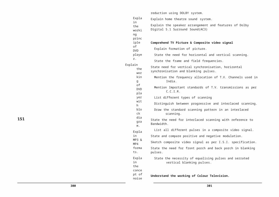
334 335
168
D:\B
acku
p\S
BTE
T_C
14\D
EC
E -
1st P
roof
- 16
8
9 To vary the speed of a 1 phase 230V AC motor using TRIAC-DIAC phase control.(3)
a) Observe the waveforms at the gate terminal and load using isolation transformer on CROb) Replace the motor with a 230 volts incandescent lamp and observe the waveforms on CROc) Measure the output power with watt meter.
Select the TRIAC & DIAC Identify the terminals Test them with DMM Rig up the circuit Observe the distorted
output wave form on CRO Measure the output power
with wattmeter
Identify the terminals Test them with DMM Rig up the circuit Observe the distorted
output wave form on CRO
Measure the output power with wattmeter
10 To assemble a PWM inverter circuit with centre tapped Transformer, Power MOSFETS and Test . .(3)
Identify the parts Assemble the parts Make Electrical
connections Connect to the battery Observe polarity Test the inverter on Load
Identify the parts Assemble the parts Make Electrical
connections Connect to the battery Observe polarity Test the inverter on
Load
11 To Vary the speed of a Small DC motor using pulse width modulation .(3)
Identify the board Note down the PWM IC
number (LM 3524) pin configuration
Note down the number of Power Transistor
Measure the speed Observe the effect of
PWM on CRO
Note down the PWM IC number (LM 3524) pin configuration
Note down the number of Power Transistor
Measure the speed Observe the effect of
PWM on CRO
12 To draw the regulation characteristics of servo stabilizer.(3)
Assemble the circuit Connect variable lamp
loadApply variable input
voltage using Auto Transformer
Measure output voltage Note upper & Lower
voltage cut off points
Apply variable input voltage using Auto Transformer
Measure output voltage Note upper & Lower
voltage cut off points
13 To assemble a servo Stabilizer and Test.(3)
Identify the partsAssemble the partsMake Electrical
connectionsTest the Servo stabilizer
on loadApply variable Input
voltageDetermine Upper &Lower
cut off VoltagesObserve rate of Voltage
correction
Assemble the parts Make Electrical
connections Test the Servo
stabilizer on load Apply variable Input
voltage Determine Upper
&Lower cut off Voltages Observe rate of Voltage
correction
14 To plot the Regulationcharacteristics of Constant Voltage Transformer. .(3)
Identify CVT and its terminals
Make Electrical connections
Connect variable lamp load
Apply variable input voltage using Auto Transformer
Measure output voltage
Identify CVT and its terminals
Make Electrical connections
Connect variable lamp load
Apply variable input voltage using Auto Transformer
Measure output voltage15 To draw the performance
characteristics of LVDT.(3) Identify LVDTConnect the set upCarefully Change the
LVDT core position and measure transducer output in steps
Identify LVDTConnect the set up Carefully
Change the LVDT core position andmeasure transducer output insteps
16 To plot the performance characteristics of Thermocouple transducer.(3)
Identify Thermocouple transducer
Prepare experimental set up
Increase the temperature in steps
Measure the output voltage
Identify Thermocouple transducer
Prepare experimental set up
Increase the temperature in steps
Measure the output voltage
17 To draw the performance characteristics of RTD.(3)
Identify RTD transducerPrepare experimental set
up Increase the temperature
in stepsMeasure the output
voltage
Identify RTD transducerPrepare experimental
set upIncrease the
temperature in steps Measure the
output voltage18 To measure the
temperature using IC LM 335.(3)
Identify LM335 IC Identify its terminalsRig up the basic circuit Increase the temperature
in stepsNote down the
Identify LM335 ICIdentify its terminalsRig up the basic circuitIncrease the
temperature in steps Note
336 337
169
D:\B
acku
p\S
BTE
T_C
14\D
EC
E -
1st P
roof
- 16
9
19 To implement an ON
/OFF temperature controller using IC LM335.(3)
Identify and select the components
Identify the terminals of LM 335
Rig up the circuitConnect the relay boardApply heat and set the cut
off temperatureTest over designed
Temperature Range
Identify and select the components
Identify the terminals of LM 335
Rig up the circuit Connect the relay board Apply heat and set the
cut off temperature Test over designed
Temperature Range
20 To draw the characteristics of Load cell.(3)
Identify Load cell transducer
Prepare experimental set up
Increase the Load in stepsMeasure the output
voltage
Identify Load cell transducer
Prepare experimental set up
Increase the Load in steps
Measure the output voltage
PART B – PLC Experiments/Simulation21 To get familiarized with
PLC tutor or PSIM PLC simulator(3)
Identify the PLCNote down the
manufacturer’s detailsGet acquainted with
symbols and ladder diagrams
Identify the sections of PSIM GUI
Identify the PLCNote down the
manufacturer’s detailsGet acquainted with
symbols and ladder diagrams
Identify the sections of PSIM GUI
22 To Implement basic logic gates using PLCsa. To implement basic
gates using PLC
b. To implement XOR XNOR gates using PLC.(3)
Implement the circuit Using PSIM
Verify the truth tables of Logic Gates
Verify the truth table of XOR &XNOR Gates
Implement the circuit Using PSIM
Verify the truth tables of Logic Gates
Verify the truth table of XOR &XNOR Gates
23 To implement delay timers using PLC.(3)
Develop Ladder diagram Implement Using PSIMSimulate and verify
Develop Ladder diagram
Implement Using PSIM
Simulate and verify24 To implement on timer and
off timer using PLC.(3)Develop Ladder diagram Implement Using PSIMSimulate and verify
Develop Ladder diagram
Implement Using PSIM
Simulate and verify
25 To implement up counter and down counter.(3)
Develop Ladder diagram Implement Using PSIMSimulate and verify
Develop Ladder diagram
Implement Using PSIM
Simulate and verify26 To implement start/Stop
Motor control.(3)Develop Ladder diagram Implement Using PSIMSimulate and verify
Develop Ladder diagram
Implement Using PSIM
Simulate and verify27 To implement Two way
switch control.(3)Develop Ladder diagram Implement Using PSIMSimulate and verify
Develop Ladder diagram
Implement Using PSIM
Simulate and verify28 To implement sequential
motor control Motors with a delay(3)
Develop Ladder diagram Implement Using PSIMSimulate and verify
Develop Ladder diagram
Implement Using PSIM
Simulate and verify
29 To implement Motor forward and reverse direction control. .(3)
Develop Ladder diagram Implement Using PSIMSimulate and verify
Develop Ladder diagram
Implement Using PSIM
Simulate and verify
30 To implement a Traffic Light controller.(3)
Develop Ladder diagram Implement Using PSIMSimulate and verify
Develop Ladder diagram
Implement Using PSIM
Simulate and verify
338 339
LIFE SKILLS
(Common to all Branches)
Subject Title : Life skills
Subject Code : EC- 508
Periods per week : 03
Period per semester : 45
TIME SCHEDULE
170
Note: No Written Examination
The students may be asked to demonstrate 1 or 2 skills from unit 2 to unit 12.
Marks: Internal – 40; External - 60
OBJECTIVES
On the completion of the course the students shall be able to
D:\B
acku
p\S
BTE
T_C
14\D
EC
E -
1st P
roof
- 17
0
Sl No. Major TopicsNo. of
periods
1. Concept of life skills 03
2. Enhancing self esteem 03
3. Goal setting 03
4. Positive attitude 03
5. Managing emotions 06
6. Stress management 06
7. Time management 03
8. Interpersonal skills 03
9. Creativity 03
10. Problem solving and Decision making skills
03
11. Assertiveness 06
12. Leadership skills &Team spirit 03
TOTAL 45
340 341
Understand the concept of Life Skills
Define Life Skills
Explain need and impact of Life Skills Programme
List the elements of Life Skills
Identify the sources of Life Skills
Understand the concept of Self esteem
Define the term self esteem
\2.2 Explain the concept of Self esteem
List the characteristics of High Self esteem
List the characteristics of Low Self esteem
Explain the advantages of High Self esteem
Explain the behaviour patterns of Low self esteem
Explain the causes of Low self esteem
List the steps to build a positive Self esteem
Practicals
Understand the concept of Goal setting
Define the term Goal
Explain the significance of Goal setting
Explain the following concepts
a) Wish b) Dream c) Goal
Explain the reasons for not setting goals
Explain effective goal setting process
List the barriers to reach goals
171
PracticalsExp No
Exercise Activity
1. Differentiate among Wish, Dream and Goal
Draw a picture of Your Self/ Your Country/ Your Society after 10yrs.
Discussion: Setting Personal Goals Story Telling Identifying of barriers Analysis barriers Overcoming barriers
Practise positive attitude
Define Attitude
Explain the concept of positive attitude
Explain the concept of negative attitude
Explain the effects of negative attitude
Identify the attitude of self and peers
Explain the effect of peers on self and vice-versa.
the steps to enhance positive attitude
Explain the strategies to enhance positive attitude
Practicals
Exp No
Exercise Activity (Psychological Instrument/ Game & Role play)
1. Identify Positive attitude To study & to identify the attitude of self and peer List & practise the strategies to enhance
positive attitude.2. Observe Positive attitudes of self and Peers
Negative attitudes of self and Peers
3. Practice Strategies to enhance Positive attitude
Celebrating success Listing successes
Practise managing emotions
Explain the concept of emotion
List the different types of emotions
Differentiate between positive and negative emotions
Identify the type of emotion
Explain the causes of different types of emotions.
D:\B
acku
p\S
BTE
T_C
14\D
EC
E -
1st P
roof
- 17
1
Exp No
Exercise Activity (Questionnaire / Game and Role play)
1.Identifying the Behaviour
Identifying the behavior patterns of low self- esteem people.
2. Practice Positive SelfEsteem
Steps to build a positive self esteem

342 343
Implement methods to manage major emotions ( anger / depression )
Define Emotional Intelligence.
Explain the method to enhance Emotional Intelligence.
PracticalsExp No
Exercise Activity (Story / simulated situational act /GD &Role play)
1. Identify the Type of Emotion To identify the type and to study the cause ofthe emotion.
2 Managing Emotions Managing major emotions -Anger andDepression
Practise stress management skills
Define Stress
Explain the concept of stress
List the types of stress
Explain the causes of stress
Comprehend the reactions to stress
a) Physical b) Cognitive c) Emotional d) Behavioural
Explain the steps involved in coping with stress by
a) Relaxation b) Meditation c) Yoga
Practice stress relaxing techniques by 3 methods.
a) Relaxation b) Meditation c) Yoga
Comprehend changing personality and cognitive patterns.
Observe changing personality and cognitive patterns.
Practicals
172
Practise some simple Stress –Relaxation Techniques, Meditation, Yoga.
Practice Time Management Skills
Define Time management.
Comprehend the significance of Time management.
Explain the strategies to set priorities.
List the steps to overcome barriers to effective Time management.
Identify various Time stealers.
Explain Time-Management skills.
List different Time-Management skills.
Comprehend the advantages of Time-Management skills.
Practicals
ExpNo
Exercise Activity ( Group work and Games)
1 Identify Time stealers Assign a activity to different Groups –Observe the time of accomplishing the task, Identify the time stealers.
2. Practice Time-Managementskills
Perform the given tasks- Games
Practise Interpersonal skills
Explain the significance of Interpersonal skills.
List the factors that prevent building and maintaining positive relationships.
Advantages of positive relationships.
Disadvantages of negative relationships
Practicals
D:\B
acku
p\S
BTE
T_C
14\D
EC
E -
1st P
roof
- 17
2

342 343
Exp No
Exercise Activity(Questionnaire /Interview and practice)
1 Identify the type of stress To study & to identify the type and causes ofstress.
2 Stress –RelaxationTechniques
Practice some simple Stress –RelaxationTechniques, Meditation, Yoga.
Exp No
Exercise Activity
1. Identify Relationships Positive Relationships, Negative Relationships – Factors that affect them- Through a story
2. Practise Rapport building Exercises on Rapport building Developing Correct Body Language

344 345
Understand Creativity skills
Define Creativity
List the synonyms like Invention, Innovation and Novelty
Distinguish between Creativity , Invention, Innovation, and Novelty
Discuss the factors that lead to creative thinking like observation and imitation , improvement etc.
Distinguish between Convergent Thinking and Divergent Thinking
Explain various steps involved in Scientific approach to creative thinking namely
a) Idea generation b) Curiosity c) Imagination d) Elaboration e) Complexity
f) Abstraction and simplification g) Divergent Thinking h) Fluency
i) Flexibility j) Persistence k)Intrinsic Motivation l) Risk taking
m) Projection/empathy n) Originality o) Story telling p) Flow.
List the Factors affecting the creativity in Individuals.
Give the concept of Vertical thinking and Lateral thinking.
Explain the importance of Lateral thinking.
Compare Lateral thinking and Vertical thinking
Practicals
ExpNo
Exercise Activity (Games and Group work)
1 Observe any given object Identifying finer details in an object2. Imagine Imagining a scene
Modifying a story (introduce a twist) Improving a product Finding different uses for a product
3 Skills Making paper craft4 Product development Brain storming session5 Developing originality Come up with original solutions for a given
problem
Understand Problem Solving and Decision Making Skills
Define a Problem
Analyze the performance problems
173
Categorize the problems
List the barriers to the solutions to problems.
Practicals
Exp No
Exercise Activity (Brainstorming – checklist technique free association, attribute listing)
1 Gathering the facts and Data and Organizing the information.
Information gathering and organizing Identifying the solutions to the problem Identifying the barriers to the solutions Zeroing on Optimum solution
2. Problem solving Games on Problem solving
Understand Assertive and Non Assertive behaviour
List the 3 types of Behaviours 1. Assertive 2. Non assertive (passive) 3. Aggressive Behaviour 4.Submissive behaiviours
Discuss the personality of a person having above behaviours
Explain the usefulness of assertive behaviour in practical situations.
Explain the role of effective communication in reflecting assertive attitude
Give examples of Assertive statements a) Assertive request b) assertive NO
Explain the importance of goal setting
Explain the method of Conflict resolution.
Discuss the methods of controlling fear and coping with criticism.
Practicals
D:\B
acku
p\S
BTE
T_C
14\D
EC
E -
1st P
roof
- 17
3

346 347
Competencies for Practical Exercises
Practise Leadership SkillsExplain the concept of leadershipList the traits of an effective leader
Distinguish between Managing and leadingList the 3 leadership styles
Compare the above styles of leadership stylesDiscuss choice of leadership style
Explain the strategies to develop effective leadership.Explain the importance of Decision makingExplain the procedure for making effective decisions.
Practicals
174
Exp No
Exercise Activity ( Games and Group work)
1 Observation Questionnaire2. Identification of a Leader Give a task and observe the leader
Discuss the qualities and his /her leadership style
Ask the other members to identify the leadership qualities
Reflection on the self3 Skills Decision making – followed by discussion4 Building Team spirit Motivation – Intrinsic and Extrinsic
Training- Communication- Challenge
D:\B
acku
p\S
BTE
T_C
14\D
EC
E -
1st P
roof
- 17
4
ExpNo
Exercise Activity ( Simulated situational act)
1 Observation of behavior Identifying different personality traits from thebody language
2. Practicing assertiveness Write statements Reaction of individuals in a tricky situation Facing a Mock interview Detailing the characteristics of peers setting goals – Games like throwing a coin
in a circle Giving a feedback on a )Successful program
b) Failed project Self disclosure
3 Skills Dealing with a critic Saying NO Dealing with an aggressive person
4 Simulation Role play- skit1. Assertive statements2. goal setting3. self disclosure
S.No Title Competency Key competencies
1. Concept of life skills Explain need and impact of Life skills
2. Enhancing self esteem Follow the steps to build a
positive self esteem
3. Goal setting Practise the effective goal setting process
4. Positive attitude
Practise the steps to enhance positive attitude.
Observe the effects of peers on self and vice-versa.
Practise the steps to enhance positive attitude
5. Managing emotions
Practise the steps to manage emotional intelligence
Identify different types of emotions
Exercise control over Emotions
Identify different types of emotions
6. Stress management Practise stress management techniques
7. Time management Practise Time management techniques
8. Interpersonal skills Identify positive and Negative Relations
9. Creativity
Lead a small group for accomplishment of a given task.
Build positive relationships.
Build positive relationships.
10. Problem solving and Decision making skills
Identify the various Problem solving and Decision making skills
Make appropriate decision
Identify the various Problem solving and Decision making skills
11. Assertive and non Assertive behaviour
Practise Assertive and non Assertive behavior
12. Leadership skills Exhibit Leadership skills Exhibit Leadership skills
348 349
COURSE CONTENT
1.0 Concept of life skills
Definition of life skills, Need and impact of life skills programme
2.0 Enhancing self esteem
Concept, Characteristics of high and low self esteem people, Advantages of high self esteem, Causes of low self esteem- Identification of behaviour patterns of low self esteem – Practice session of Questionnaire / Game-Steps to build positive self esteem – Practice session of Role play
3.0 Goal setting
Significance of goal setting,Concepts of Wish, Dream, and Goal Identify Wish, Dream, and Goal and differentiate among them. Reasons for not setting the goals, Barriers to reach goals,Identify Barriers, Effective goal setting process & Practise Effective goal setting
4.0 Positive attitude
concept effects of negative attitude,attitude of self and peers,effect of peers on self and vice-versa, steps to enhance positive attitude,strategies to enhance positive attitude
5.0 Managing emotions
Problem-definition, performance problems ,Categorize the problems, barriers to the solutions to problems.
6.0 Stress management
concept of stress, Types of stress, causes of stress, reactions of stress, coping with stress, stress relaxing techniques, changing personality and cognitive patterns
7.0 Time management
Definition, significance of various Time stealers, Time management, strategies to set priorities, steps to overcome barriers, Time- Management skills- its advantages.
8.0 Interpersonal skills
Significance of Interpersonal skills,positive relationships- Advantages, negative relationships- Disadvantages
9.0 Creativity
Definition, Invention, Innovation, Novelty,Creative Thinking , observation and imitation, improvement, Expertise, skill, and motivation, components of Creativity, Convergent Thinking and Divergent Thinking, various steps involved in Scientific approach to creative thinking namely, Factors
175
affecting the creativity in Individuals, Vertical Thinking and Lateral Thinking.
10.0 Problem solving and Decision making skills
Definition, performance problems –analysis, categorizing,barriers to the solutions to problems.
11.0 Assertive and non Assertive behaviour
Types of Behaviours – their characteristics, need for controlling and avoiding aggressive behaviours, making and refusing an assertive request – their evaluation, importance of goal setting, method of giving feed back.
12.0 Leadership skills
Concept , importance, Role of a Leader in an Organization, Traits of an effective leader, Managing and leading, leadership styles-their comparison, theories of leadership, strategies to develop effective leadership, importance of Decision making, concept of ethical leadership and moral development.
REFERENCE
1. Robert Nlussier, Christopher F. Achua Leadership: Theory, Application, & Skill development: Theory, Application.
D:\B
acku
p\S
BTE
T_C
14\D
EC
E -
1st P
roof
- 17
5

350 351
MICROCONTROLLER APPLICATIONS LAB PRACTICE
SUBJECT TITLE : Microcontroller Applications Lab Practice
SUBJECT ODE : EC-509
PERIODS/WEEK : 03
PERIODS/SEMESTER : 45
Rationale: Microcontroller Applications Lab Practice is included in the same semester to ensure contiguity and give an opportunity for the students to reinforce their theoretical knowledge by practically verifying in the laboratory. care has been taken to match the Experiments with field requirements.
TIME SCHEDULE
2. Practice Arithmetic instructions of 8051
a) Write an ALP to demonstrate Addition , subtraction , division and multiplication of 8 bit numbers using immediate data access.
b) Write an ALP to Add and Subtract 16 bit numbers
c) Write an ALP to find the Square and Cube of a decimal number
d) Write an ALP to find LCM of given 3 decimal numbers
e) Write an ALP To find HCF of given 3 decimal numbers
3. Practice Data transfer instructions
a) Write an ALP to Block move - 10bytes of data from 0X30-0X39 to 0X40- 0X49 (without overlap)
b) Write an ALP to Block move - 10bytes of data from 0X30-0X39 to 0X35- 0X39 (with overlap)
c) Write an ALP to Block exchange – 10bytes of data between 0X30-0X39 to 0X40-0X49
d) Write an ALP to Block move - 10bytes of data from 0X30-0X39 to 0X1000-0X1009 (Internal to external memory or vice versa)
LIST OF EXPERIMENTS
I. Familiarization with Microcontroller Kit & Simulators
1. Practice with microcontroller kits and Simulators
a) Familiarize with 8051 Microcontroller Kit
b) Familiarize with 8051 simulator EDSIM 51 ( or similar)
c) Write small ALP to verify different register addressing techniques
II . 8051 Instruction set
176 4. Practice Data Manipulation
a) Find Smallest/Largest number in 10bytes of data from 0X30-0X39 (R3 – should store the smallest/largest number and R4 – should store address of the smallest/largest number)
b) Search for an element in the 10 bytes of data from 0X30-0X39 (R3 =1, if element is found else R3=0)
c) Sort 10bytes of data from 0X30-0X39 in Ascending order
d) Sort 10bytes of data from 0X30-0X39 in Descending order
5. Practice Boolean & Logical instructions :
a)Find 2’s complement of a number using (CPL) instruction
b) Convert Packed to Unpacked BCD (bit Masking) Using (ANL)Instruction
c)Convert ASCII to BCD Using(XRL) instruction.
III. I mplement Counters ,Timers Interrupts and Flags
D:\B
acku
p\S
BTE
T_C
14\D
EC
E -
1st P
roof
- 17
6
S. No. EXPERIMENTS No. of Periods
1. Practice with Microcontroller Kit 06
2. Practice Instruction set 09
3. Implement Counters, Timers Interrupts and Flags 15
4 Practice Interfacing 15
Total 45

352 353
6. Implement a HEX up/down counter - (Program should check value @R0=0X30, if 0X30=0 then up counter else down counter)
a) implement BCD(00-99) up/down counter - (Program should check value @R0=0X30, if 0X30=0 then up counter else down counter)
7. Implement Delays and Timers
a) Write a program in assembly language and in “C” produce required time delay a) by Using instructions only b) by Using Timers
b)Write a program in assembly language and C to verify Call and return instructions with port programming
c) Write a program in assembly language and C to verify Logical or Delay loop using Call and return instructions
8. Use 8051 Interrupts and Flags
Write a program to generate a square wave of 50 Hz on pin 1.2 . Assume that crystal frequency is 11.0592 MHz using timer.
IV . Practice Interfacing Techniques
9. Micro controller interfacing
a) Interfacing Switches and LEDS to 8051
i) Make an LED connected to port 1.5, light up for specific time on pressing a switch connected to port 2.3
ii) Write a Program to make an LED connected to pin 1.7 to blink at a specific rate
i ii) Connect a Relay in place of LED to control a AC 230 V Lamp
10. Interface 3-digit 7SEGMENT LED DISPLAY using timer for digit scan
a) Interface a Single DOTMATRIX DISPLAY and display the given number
11. Interface a (3x4 matrix) Key Board to 8051
177
12. Control the direction of rotation of a small DC motor
13. Interface I2 C BUS Device using DS1307 IC .
a) Interface a) ADC IC b) DAC IC
b) Interface Microcontroller serial interface to PC COM port
14. Burn executable code into EPROM
a) Burn executable code into flash memory for 89C51
D:\B
acku
p\S
BTE
T_C
14\D
EC
E -
1st P
roof
- 17
7
354 355
Competencies and Key Competencies
178
D:\B
acku
p\S
BTE
T_C
14\D
EC
E -
1st P
roof
- 17
8
3 To Write an ALP to Block move - 10bytes of data from 0X30-0X39 to 0X40-0X49(without overlap) (3)
a) Write an ALP to Block move - 10bytes of data from 0X30-0X39 to 0X35-0X39 (with overlap)
b) Write an ALP to Block exchange – 10bytes of data between 0X30-0X39 to 0X40-0X49
c) Write an ALP to Block move - 10bytes of data from 0X30-0X39 to 0X1000- 0X1009 (Internal to external memory or vice versa)
Enter the ALP at the specified address and execute
Use DATA Transfer Instructions
Use the simulator for the same ALP and verify the Memory contents
Enter the ALP at the specified address and execute
Use Arithmetic Instructions
Use the simulator for the same ALP and verify the register contents
4 To Practice Data Manipulation (3)
a) To find Smallest/Largest number in 10bytes of data from 0X30-0X39 (R3 – should store the smallest/largest number and R4 – should store address of the smallest/largest number)
b) To Search for an element in the 10 bytes of data from 0X30-0X39 (R3 =1, if element is found else R3=0)
c) To Sort 10bytes of data from 0X30-0X39 in Ascending order
d) To Sort 10bytes of data from 0X30-0X39 in Descending order
Enter the ALP at the specified address and execute
Use Logical Instructions
Use the simulator for the same ALP and verify the result
Enter the ALP at the specified address and execute
Use Arithmetic Instructions
Use the simulator for the same ALP and verify the register contents
Exp No
Name of the Experiment
(No of Periods)
Competencies Key Competencies
1 To practice with microcontroller kits and Simulators (3)
a) To Familiarize with 8051 Microcontroller Kit
b) To Familiarize with 8051 simulator EDSIM 51 ( or similar)
c) To Write small ALP to verify different register addressing techniques
Identify the component assemblies in the kit
Enter the ALP at the specified address and execute
Use the simulator for the same ALP and verify the register contents and the Flags
Enter the ALP at the specified address and execute
Use the simulator for the same ALP and verify the register contents and the Flags
2 To Practice Arithmetic instructions of 8051 (3)
a) Write an ALP to demonstrate Addition , subtraction , division and multiplication of 8 bit numbers using immediate data access.
b) Write an ALP to Add and Subtract 16 bit numbers
c) Write an ALP to find the Square and Cube of a decimal number
d) Write an ALP to find LCM of given 3 decimal numbers
e) Write an ALP To find HCF of given 3 decimal numbers
Enter the ALP at the specified address and execute
Use Arithmetic Instructions
Use the simulator for the same ALP and verify the register contents
Enter the ALP at the specified address and execute
Use Arithmetic Instructions
Use the simulator for the same ALP and verify the register contents

356 357
179
D:\B
acku
p\S
BTE
T_C
14\D
EC
E -
1st P
roof
- 17
9
5 To implement a HEX up/down counter - (Program should check value @R0=0X30, if 0X30=0 then up counter else down counter)
(3)
b) To implement BCD(00-99) up/down counter - (Program should check value @R0=0X30, if 0X30=0 then up counter else down counter)
Enter the ALP at the specified address and execute
Use timer/Counter
Enter the ALP at the specified address and execute
Use timer/Counter
6 To implement a HEX up/down counter - (Program should check value @R0=0X30, if 0X30=0 then up counter else down counter) (3)
a) To implement BCD(00-99) up/down counter - (Program should check value @R0=0X30, if 0X30=0 then up counter else down counter)
Enter the ALP at the specified address and execute
Use timer/Counter
Enter the ALP at the specified address and execute
Use timer/Counter
7 To Implement Delays using Timers (3)
a) To write a program in assembly language and in “C” produce required time delay a) by Using instructions only b) by Using Timers
b)To write a program in assembly language and C to verify Call and return instructions with port programming
c) To write a program in assembly language and C to verify Logical or Delay loopusing Call and return
Enter the “C” program in the simulator
Debug and execute Use CALL and RET
Instructions
Verify STACK Contents in the Simulator
Enter the “C” program in the simulator
Debug and execute Use CALL and RET
Instructions
Verify STACK Contents in the Simulator
8 To Use 8051 Interrupts and Flags (3)
To Write a program to generate a square wave of 50 Hz on pin 1.2 . Assume that crystal frequency is 11.0592 MHz using timer.
Enter the ALP at the specified address
Calculate the
Timer Data to be loaded for 50 Hz
Execute the Program
Enter the ALP at the specified address
Calculate the
Timer Data to be loaded for 50 Hz
Execute the Program
9 Micro controller interfacing
a) Interfacing Switches and LEDS to 8051 (3)
i) To make an LED connected to port 1.5, light up for specific time on pressing a switch connected to port 2.3
ii) To Write a Program to make an LED connected to pin 1.7 to blink at a specific rate
ii) To Connect a Relay in place of LED to control a AC 230 V Lamp
Enter the ALP at the specified address
Rig up the circuit
Execute the Program
Enter the ALP at the specified address
Rig up the circuit
Execute the Program
10 To Interface 3-digit 7SEGMENT LED DISPLAYusing timer for digit scan (3)
a) To Interface a Single DOTMATRIX DISPLAY and display the given number
b) To Interface a (3x4 matrix)Key Board to 8051
c)To control the direction of rotation of a small DC motor
Rig Up the circuit Enter The C
Program in the simulator
Debug and Execute
Rig Up the circuit Enter The C
Program in the simulator
Debug and Execute
11 To Interface a (3x4 matrix) Key Board to 8051 (3)
Rig Up the circuit Enter The C Program
in the simulator
Rig Up the circuit Enter The C Program
in the simulator

358 359
FIELD PRACTICES
Subject Title : Field Practices
Subject code : EC-510
Periods/Week : 07
Periods/Semester : 105
Rationale: Field practices subject is introduced as an alternate for industrial Training. This course is aimed at imparting same skills a student would acquire in the industry during the initial training period. in other words industry like environment is simulated in the institution during this course to prepare the students for Industry.
TIME SCHEDULE
180
Note :
i), All the seven periods should be conducted on the same day for practice and to ensure contiguity.
ii) General List Of Industry Practices are mentioned ( Other Industry practices may be added)
I. Standard practices in the Industry
D:\B
acku
p\S
BTE
T_C
14\D
EC
E -
1st P
roof
- 18
0
12 To control the direction of rotation of a small DC motor (3)
.
Rig Up the circuit Enter The C Program
in the simulator Debug and Execute
Rig Up the circuit Enter The C Program
in the simulator Debug and Execute
13 To interface I2 C BUS Device using DS1307 IC . (6)
a) To interface i) ADC ICii) DAC IC
b) To interface Microcontroller serial interface to PC COM port
Rig Up the circuit Enter The C Program
in the simulator Debug and Execute
Rig Up the circuit
Enter The C Program in the simulator
Debug and Execute
14 To Burn executable code into EPROM (3)
b) To burn executable code into flash memory for 89C51
Compile the C Program
Use the Programmer SW to Load the .HEX file into the Programmer Memory
To burn the code into EPROM/FLASH Memory of Controller
To SECURE the CODE by programming the LOCK feature
Compile the C Program
Use the Programmer SW to Load the .HEX file into the Programmer Memory
To burn the code into EPROM/FLASH Memory of Controller
To SECURE the CODE by programming the LOCK feature
S. No. EXPERIMENT No. of Periods
1. Standard practices in the Industry 10
2. Manufacturing 35
3. Maintenance & Servicing 36
4 Organising 12
5 Documentation &Data processing 12
Total 105
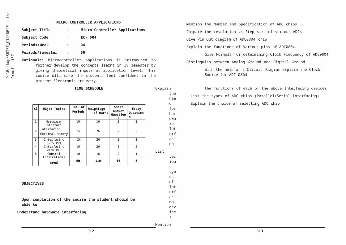
360 361
1. Practice Industrial Safety, First Aid, dress code, tie, shoe etc…)
i) To Keep workplace clean and tidy.
ii)To handle material with due precautions and care
iii) To maintain/house keeping the Laboratories/work area
iv) To follow Industry Mannerisms and Etiquette ( Greeting , Smiling , Shaking hands - Polite conversation, Requesting etc) –To practice the use first aid and fire extinguishers
II . Manufacturing
2. a) carry out following activities
i) Prepare wires ii) Practice wire bunching iii) Make wire tips/joints iv)Keep the component set ready for population on PCB
b) Set up layout for work space for fabrication .
c) Supervise Manufacturing/ Testing activities.
3. Practice soldering of SMD components
4. Design /Prepare drawing for an electronic circuit/ equipment i) Manuallyii) Using software tools
5. Fabricate /Rig up Prototype circuit
i) To prepare circuit boards for the experiments mentioned in the curriculum and test.
6. Prepare required test jigs or circuits for the above and test
7. Trouble shoot the faults in the equipment using CRO, DMM, Logic Analyzer etc.
8. Carry out Reverse Engineering(Decode the circuit from a circuit board and interpret/identify the circuit
9. Follow the standard procedures/Instructions given in the Equipment manual to operate and set up the equipment
10. Work with sophisticated tools/equipment used in electronic industry as per standard procedure
11. Use software tools like Pspice , Multisim , Matlab etc and design the circuits
181
12. Carry out Quality assurance Tests
III. Maintenance & Servicing
13. Maintain
a) Electrical wiring/equipment in the laboratory
b) Institute Earthing
c) UPS Batteries
14. Maintain/Troubleshoot computers and Computer Networks in the institute
15. Install and Test equipment like i) UPS ii) inverters, iii) Servo stabilizers
IV. Organising
16. Prepare
i) Inventory,
ii) follow industry procedures,
iii) Maintain log
iv) housekeeping v) Documentation
17. Carry out market survey to find the resources , Equipment suppliers etc.
18. Organize seminars , Events and presentations.
i) To Set up Computer-LCD projector / PA system , etc
I. Documentation &Data processing
19. practice Data processing on computer
i) Browse the internet and search for the most relevant information on latest trends in communication engineering (or any other engineering topic) and prepare a report /presentation
20. Prepare Project reports/Manuals for the kits prepared
D:\B
acku
p\S
BTE
T_C
14\D
EC
E -
1st P
roof
- 18
1

362 363
Competencies and Key Competencies to be achieved
182
D:\B
acku
p\S
BTE
T_C
14\D
EC
E -
1st P
roof
- 18
2
4 To Design /Prepare drawing for an electronic circuit/ equipment i) Manually ii) Using software tools
Prepare drawings/Circuits and layouts both manually and by using computer
Prepare drawings/Circuits and layouts both manually and by using computer
5 To fabricate /Rig up Prototype circuit
To prepare prototypes Carry out
necessary modifications
Testing Troubleshooting Search resources
To prepare prototypes
Carry out necessary modifications
TestingTroubleshootingSearch resources
6 To prepare required test jigs or circuits for the above and test
Prepare/Design suitable test jigs
Test the circuits
Prepare/Design suitable test jigs
Test the circuits7 To Trouble shoot the faults in
the equipment using 4 Channel DSCRO DMM, Logic Analyzer Spectrum analyzer etc.
Identify the fault Troubleshoot Replace/Substitute Rectify the problem
Identify the faultTroubleshootReplace/SubstituteRectify the problem
8 To carry out Reverse Engineering(Decode the circuit from a circuit board and interpret/identify the circuit
Reading the circuit Diagrams
Identifying the circuit in the PCB
Decoding the circuit Preparing a drawing Verifying the drawing Implement the circuit Testing the circuit Modifying Prepare prototype
Reading the circuit Diagrams
Identifying the circuit in the PCB
Decoding the circuitPreparing a drawing
Verifying the drawing
Implement the circuit
Testing the circuitModifyingPrepare prototype
9 To follow the standard procedures/Instructions given in the Equipment manual to operate and set up the equipment
Read the Instructions and Follow
operate the equipment as per procedure
Verify the results
Read the Instructions and Follow
operate the equipment as per procedure
Verify the results10 To work with sophisticated
tools/equipment used in electronic industry as per standard procedure
work with sophisticated tools/equipment used in electronic industry as per standard procedure
Follow due
work with sophisticated tools/equipment used in electronic industry as per standard procedure Follow due
Exp No
Name of the Experiment Competencies Key Competencies
1 To Practice Industrial Safety, First Aid, dress code, tie, shoe etc…)
i) To Keep workplace clean and tidy.
ii) To maintain the Laboratories
iii)To follow Industry Mannerisms and Etiquette ( Greeting , Smiling , Shaking hands - Polite conversation, Requesting etc) –
iv)To practice the use firstaid and fire extinguishers
Clean the equipment Follow Industry
mannerisms Use first aid &act under
emergencies Maintain Laboratories
Follow Industry mannerisms
Maintain Laboratories Use first aid &act
under emergencies
2 To carryout following activities To prepare
Wire tips Bunching Select components Set up experiment Supervise
To prepareWire tipsBunchingSelect componentsSet up experimentSupervise
i) prepare wires ii) Practice wirebunching iii) Make wiretips/joints iv) Keep thecomponent set ready forpopulation on PCB
b)To Prepare layout forworkspace to carry fabrication
c)To Supervise fabricationactivities
3 To Practice soldering of SMD components
Handle SMD components
Solder SMD components with proper precautions
Testing the solderedjoints
Handle SMD components
Solder SMD components with proper precautions
Testing thesoldered joints

364 365
183
D:\B
acku
p\S
BTE
T_C
14\D
EC
E -
1st P
roof
- 18
3
17 To carry out market research to find the resources
Identify the product/component
Search for similar / same items
Compare features Check
thePrice/cost effectiveness
Test the product for suitability
Find the Suppliers
Identify the product/component
Search for similar / same items
Compare featuresCheck the cost effectiveness
Test the product for suitability
Find the Suppliers
18 To organize seminars Events and presentations.
i) To Set up Computer- LCD projector / PA system , etc
Organize Events/Seminars
Exhibit Leadership qualities
Show Creativity Time management
skills Set up laptop LCD
projector etc for the event
Organize Events/Seminars
Exhibit Leadership qualities
Demonstrate Creativity
Use Time management skills
Set up laptop LCD projector etc for theevent
19 To practice Data processing on computer
i) To browse the internet and search for the most relevant information on latest trends in communication engineering (or any other engineering topic) and prepare a report /presentation
Use computer Browse internet
&search Download
information Convert formats Prepare reports Prepare
Presentation Save them into
cloud storage
Use computer forChecking mails/assignments/ notices etc
Upload /Download information
Search the web for required information
Prepare laboratory Documentation
20 To prepare Project reports/Manuals for the kits prepared
Use MS Word Browse and search
the internet Download
information Convert formats
Use MS WordBrowse and search the internet
Download information
Convert formats
11 To use software tools like Pspice, Multisim , Matlab or any other simulation sofwares. and design the circuits
use software tools like Pspice , Multisim , Matlab etc for designing the circuits
Implement the circuit
Modify usingsoftware tools
use software tools like Pspice , Multisim , Matlab etc for designing the circuits
Implement the circuit
Modify usingsoftware tools
12 To Carry out Quality assurance Tests
Use test equipment Follow pre testing
&Post testing procedures
Troubleshoot Design
Use test equipmentFollow pre testing &Post testing procedures
TroubleshootDesign
13 To maintain a) Electrical wiring/equipment in the laboratory b) Institute Earthing c) UPS Batteries
Replace fuses- Repair Power cords Replace faulty
Sockets and Plugs Replace faulty
Tube lights/Lamps Maintain earthing Maintain UPS
Batteries
Replace fuses-Repair Power cordsReplace faulty Sockets and Plugs
Replace faulty Tube lights/Lamps
Maintain earthingMaintain UPS Batteries
14 To maintain/Troubleshoot computers and Computer Networks in the institute
Act as Computer administrator in the computer lab
Maintain LAN Install/Run Antivirus Remove unwanted
files Rectify any
computer problems
Act as Computer administrator in the computer lab
Maintain LAN Install/Run AntivirusRemove unwanted files
Rectify any computer problems
15 To Install and Test equipment
like i) UPS ii) inverters, iii) Servo stabilizers
Install Laboratory Equipment as per procedure
Install UPS Make special wiring
for UPS/Inverter Install Servo
Stabilizer
Install Laboratory Equipment as per procedure
Install UPSMake special wiring for UPS/Inverter
Install Servo Stabilizer
16 To prepare i) Inventory ii) follow industry procedures, iii) Maintain log iv) housekeeping
Prepare Bill of materials
Material requirement
Place indent Maintain log Reporting House keeping
Prepare Bill of materials
Material requirement
Place indentMaintain logReportingHouse keeping
366 367
DIPLOMA IN ELECTRONICS & COMMUNICATION ENGINEERING
SCHEME OF INSTRUCTIONS AND EXAMINATIONS
VI Semester
VI SEMESTER
184
Note:
1. Five local industrial visits / Interaction, one for each of the courses listed from EC 602 to EC 606 may be arranged to enable the students to have industry exposure.
2. Duration: one week The students need to submit a write up of two to three pages mentioning all salient learning experiences like advance in technology, its evaluation, application, advantages & disadvantages, expected changes in future etc.,.
3. Industries: Embedded systems ,Power electronics, Cellular communication etc
D:\B
acku
p\S
BTE
T_C
14\D
EC
E -
1st P
roof
- 18
4
Subject Code
Name of the Subject
Instructionperiod / week
Total Period/ Sem
Scheme of Examination
TheoryPractical/Tutorial
Duration(hours)
SessionalMarks
EndExam
TotalMarks
THEORY:
EC- 601Advanced CommunicationSystems
4 - 60 3 20 80 100
EC-602Data communication & ComputerNetworking
4 - 60 3 20 80 100
EC - 603 Optical Fibre Communication
4 - 60 3 20 80 100
EC - 604 Computer Hardware 4 - 60 3 20 80 100
EC - 605Advanced Microcontrollers &DSP
4 - 60 3 20 80 100
EC - 606Digital CircuitDesign through Verilog HDL
4 - 60 3 20 80 100
PRACTICAL:
EC- 607Computer HW, Networking & OFC Lab Practice
- 6 90 3 40 60 100
EC -608Verilog HDL Programming LabPractice
- 3 45 3 40 60 100
EC -609Advanced Microcontroller Lab Practice
- 3 45 3 40 60 100
EC-610 Project work - 6 90 3 40 60 100
TOTAL 24 18 630 280 720 1000

368 369
ADVANCED COMMUNICATION SYSTEMS
Subject Title : Advanced Communication Systems
Subject Code : EC-601
Periods/Week : 04
Periods/Semester : 60
Rationale: Advanced Communication systems subject is a core subject aimed to impart sufficient theoretical inputs in Transmission lines Microwave devices, Radars, and satellite communication to keep in pace with the fast changing technology.
TIME SCHEDULE
Sl Major Topics No. of periods
Weightage of marks
ShortAnswer
QuestionsEssay
Questions1 Transmission Lines 10 16 2 1
2 Microwave components andTubes 14 26 2 2
3 Microwave semiconductor devices and MICs 10 16 2 1
4 RADAR 13 26 2 2
5 Satellite Communication 13 26 2 2
Total 60 110 10 8
OBJECTIVES
Upon completion of the course the student should be able to
Understand the working of Transmission Lines
List different types of Transmission Lines.
Draw the Electrical equivalent circuit of a Transmission line.
Define Primary and Secondary constants of a Transmission line.
Explain the transmission line equations
Derive the expressions for attenuation and phase constants
Define group and phase velocities in transmission lines
185
Explain the concept of Infinite Line
Define lossless Line
List two types of distortions in transmission lines
Derive the condition for distortion less line
Define Reflection coefficient and SWR
Derive the relation between Reflection Coefficient & SWR
Explain the need for impedance matching in transmission lines.
Impedance Matching using quarter wave transmission line.
Explain single stub matching in transmission lines.
Microwave Components and Tubes
State the need for microwave devices.
the various bands in microwave frequency range.
Define rectangular and circular waveguides.
Explain Boundary conditions for Rectangular waveguides
Explain various modes of operation of waveguides.
Define dominant mode and cut-off wavelength in rectangular waveguide.
Calculate the cut-off frequency, cut-off wavelength, guide wavelength, phase velocity, group velocity and characteristic impedance in rectangular waveguide.
State the need for microwave bends, corners and twists
List different T-Junctions
Explain the working of E-Plane Tee and H-Plane Tee.
Explain the working of Magic Tee
State the need for isolators and circulators
Explain the working of Isolator
Explain the working of Circulator.
Explain the construction and working of Multi cavity Klystron amplifier.
List the applications of Multi cavity Klystron and Cavity resonator
Explain the construction and working of Reflex Klystron oscillator
List the applications of Reflex Klystron.
D:\B
acku
p\S
BTE
T_C
14\D
EC
E -
1st P
roof
- 18
5

370 371
Explain the construction and working of Magnetron oscillator
List the applications of Magnetron.
Explain the construction and working of Travelling Wave Tube amplifier
List the applications of TWTA.
Microwave Semiconductor Devices and MICs
State the need for microwave semiconductor devices
Distinguish between ordinary semiconductor devices and microwave semiconductor devices.
Define Gunn Effect.
Explain constructional features and working principle of GUNN diode
List the applications of GUNN diode.
State the Tunnelling phenomena
Explain the working of Tunnel diode
List the other semiconductor microwave devices like IMPATT and TRAPPAT diodes
List the applications of IMPATT & TRAPATT diodes
List the advantages of microwave semiconductor devices over electron beam devices.
State the need for Microwave Integrated Circuits (MICs)
Explain the working of micro-strip antenna
List the applications of micro-strip antennas.
Understand the principles of RADAR
State the basic principle of Radar with a block diagram.
Derive the basic Radar range equation.
Predict the range performance factors from range equation.
Draw and explain the block diagram of pulsed Radar system.
State the need for duplexer in Radar
Explain the working of branch type Duplexer with sketch.
List the types of indicators used in radar systems.
186
Briefly explain A-scope and PPI displays.
State the disadvantages of pulsed radar.
Explain the Doppler Effect.
Explain the principle of CW radar
Draw and explain the block diagram of CW radar.
List the limitations of a CW Radar
Explain the working of FM CW Radar.
Explain the application of FM CW Radar as altimeter
Draw and explain the block diagram of MTI Radar.
List the applications of various Radar systems.
Explain the principle of instrument landing system.
Understand the principle of working of satellite communication
State the need for satellite communication
Define foot print of a satellite
Explain the basic structure and uses of microwave links.
Explain fixed microwave link with block diagram.
List the advantages of satellite communication over terrestrial radio communication.
Explain geostationary satellites and satellites in lower orbits.
List the advantages and disadvantages geostationary satellites.
Define azimuth and elevation with reference to satellites.
Define terms apogee and perigee.
Define uplink frequency and down link frequency
List the functions of a transponder
List three types transponders used in satellites (single conversion, double conversion and regenerative)
Explain the working of the three types of transponders.
Explain bandwidth allocation of a satellite.
List the three methods of increasing satellite capacity
D:\B
acku
p\S
BTE
T_C
14\D
EC
E -
1st P
roof
- 18
6

372 373
Explain the methods of increasing channel capacity. Frequency reuse, polarization and spatial isolation).
Draw and explain the block diagram of communication satellite.
Draw and explain the block diagram of Earth station.
Explain the working of GPS
List the applications of satellites.
COURSE CONTENT
1. Transmission Lines:
types of Transmission Lines- Electrical equivalent circuit of a Transmission line- Primary and Secondary constants of a Transmission line-Transmission line equations-Expressions for attenuation and phase constants-Group and phase velocities in transmission lines-Concept of Infinite Line-Lossless Line-Types of distortions in transmission lines- Condition for distortion less line- Reflection coefficient and SWR-Relation between Reflection Coefficient & SWR-Need for impedance matching in transmission lines-Impedance Matching using quarter wave transmission line- Single stub matching in transmission lines.
2. Microwave components and Tubes:
Need for microwave devices-Various bands in microwave frequency range-Rectangular and circular waveguides- Boundary conditions for Rectangular waveguides-Various modes of operation of waveguides- Dominant mode and cut-off wavelength in rectangular waveguide- Calculation of cut-off frequency, cut-off wavelength, guide wavelength, phase velocity, group velocity and characteristic impedance in rectangular waveguide-Need for microwave bends, corners and twists- T-Junctions- Working of E-Plane Tee and H-Plane Tee- Working of Magic Tee-Need for isolators and circulators- Working of Isolator- Working of Circulator- Construction and working of Multi cavity Klystron amplifier- Applications of Multi cavity Klystron-Cavity resonator- Construction and working of Reflex Klystron oscillator- Applications of Reflex Klystron- Construction and working of Magnetron oscillator- Applications of Magnetron- Construction and working of Travelling Wave Tube amplifier- Applications of TWTA.
3. Microwave Semiconductor Devices and MICs:
Need for microwave semiconductor devices-Ordinary semiconductor devices and microwave semiconductor devices-Gunn Effect-Explain constructional features and working principle of GUNN diode-
187
Applications of GUNN diode- Tunnelling phenomena-Working of Tunnel diode-Other semiconductor microwave devices like IMPATT and TRAPPAT diodes-Applications of IMPATT & TRAPATT diodes-Advantages of microwave semiconductor devices over electron beam devices-Need for Microwave Integrated Circuits (MICs)-Working of micro-strip antenna- Applications of micro-strip antennas.
4. Principles of RADAR:
Basic principle of Radar with a block diagram-Basic Radar range equation-Range performance factors from range equation-Block diagram of pulsed Radar system-Need for duplexer in Radar-Working of branch type Duplexer with sketch-Types of indicators used in radar systems- A- scope and PPI displays-Disadvantages of pulsed radar- Doppler Effect- Explain the principle of CW radar-Block diagram of CW radar-Limitations of a CW Radar-Working of FM CW Radar-Application of FM CW Radar as altimeter-Block diagram of MTI Radar-Applications of various Radar systems-Principle of instrument landing system.
5. Satellite Communication:
Need for satellite communication-Foot print of a satellite-Basic structure and uses of microwave links-Fixed microwave link with block diagram- Advantages of satellite communication over terrestrial radio communication-Geostationary satellites and satellites in lower orbits- Advantages and disadvantages geostationary satellites-Azimuth and elevation with reference to satellites-Apogee and perigee-Uplink frequency and down link frequency-Functions of a transponder-Types of transponders used in satellites (single conversion, double conversion and regenerative)-Working of the three types of transponders-Bandwidth allocation of a satellite-Methods of increasing satellite capacity-Methods of increasing channel capacity- Frequency reuse, polarization and spatial isolation)-Block diagram of communication satellite-Block diagram of Earth station-Working of GPS-Applications of satellites.
REFERENCE BOOKS:
1. Electronic communication system by George Kennedy, TMH
2. Electronic communications systems by Roy Blake, Thomson Delmar,2002.
3. Introduction to RADAR Engineering by Merryl I Skolnik. TMH
4. Microwave Integrated circuits by Samuel Leo 3 ed.-Prentice Hall
D:\B
acku
p\S
BTE
T_C
14\D
EC
E -
1st P
roof
- 18
7
374 375
DATA COMMUNICATIONS AND COMPUTER NETWORKS
Subject Title : Data Communications and Computer Networks
Subject Code : EC-602
Periods/Week : 04
Periods/Semester : 60
Rationale: The Knowledge of Data communications and communication and computer networks is essential for Electronics & Communication engineering students as everything from Banking to Railway ticket booking being completely computerized there are ample opportunities for the students to get good jobs .
TIME SCHEDULE
Sl Major Topics No. of periods Marks
ShortAnswer
QuestionsEssay
Questions
1
Basics of Data communication and OSI Layer
10 21 2 1 ½
2Concepts of LAN & DLL Protocols 16 26 2 2
3IP addressing & Network LayerProtocols
12 21 2 1 ½
4 WAN Protocols 10 21 2 1 ½
5Web Applications & Network Security 12 21 2 1 ½
Total 60 110 10 8
OBJECTIVES
Upon completion of this course the student should be able to:
Understand the Basics of Data communication & OSI Layer
Define data communication
188
State the need for data communication networking.
Distinguish between analog and digital data.
Define computer network and state its use.
Draw the ISO: OSI 7 layer architecture and explain the function of each layer.
List the different types of physical transmission media.
Explain the use of UTP, STP, Coaxial and Fiber optic cable in networking.
Define simplex, half-duplex and full-duplex communication.
Define bandwidth and throughput of a physical medium.
List the three types of switching techniques used in networking.
Explain circuit switching, packet switching and message switching.
Explain virtual circuit
Explain datagram approach in packet switching
Understand the concepts of LAN and DLL protocols
Define Local area network and state its use.
Explain different network topologies (Bus, Star, Ring)
Compare the performances of the three topologies.
Explain the working of token ring network.
Explain the use of different networking devices such as repeater/hub, switch, bridge in constructing networks
Differentiate between repeater, switch and bridges.
State the need for protocols in computer networks.
State the need for framing in data link layer.
Explain the Ethernet frame format (IEEE 802.3).
State the need for flow control and error control protocols.
Explain the point-to-point protocol (PPP).
Explain CSMA/CD and CSMA/CA.
Explain the topology of wireless LAN and explain its frame format (IEEE 802.11).
Discuss FDDI and its properties.
D:\B
acku
p\S
BTE
T_C
14\D
EC
E -
1st P
roof
- 18
8

376 377
Explain the Bluetooth technology.
Mention the applications of WAP.
Explain the features of UDP
Explain the connectivity of systems using TCP & UDP
Explain the use of Gateways.
Understand IP addressing and Network layer protocols
Define the terms Internet and Intranet.
Define internet protocol.
Distinguish between connection oriented (virtual circuit) and connectionless (datagram) services.
Classify the two types of Internet Protocol addressing IPv4 and IPv6 and state the need for IPv6.
Explain classful addressing and classless addressing in IPv4.
Explain Internet protocol version-6 (IPv6) addressing.
Explain the use of routers in networking
Explain the concept of routers and routing.
Define cut through & store-and-forward and adaptive switch mechanisms.
Explain the packet transfer mechanism using routers and IP address.
Explain the internal architecture of ISP.
Explain Dial up access, leased line, DSL, ISDN types of internet connectivity for an individual user/ organization.
Understand WAN protocols
Explain WAN architecture.
List the three commonly used WAN technologies.
Explain the working of X.25 WAN Protocol
Explain the FRAME relay WAN Protocol.
Explain ATM WAN Protocol.
Explain the ARPANET and WWW.
Explain different layers of TCP/IP.
Explain the features of TCP.
Explain Address Resolution Protocol (ARP).
Mention the functions of port and sockets.
189
Understand Web Applications & Network security.
Mention the role of DNS server.
Explain DNS namespace.
Explain how email is transferred.
Explain POP server and SMTP server.
Explain file transfer operation using FTP
Explain the working of Web server.
Explain the working of Web browser.
List HTTP commands.
Explain the purpose of proxy server.
Explain the use of hyperlinks.
Explain the web browser architecture.
Explain remote login.
State the need for network security.
List various security services.
Define message confidentiality and message integrity
Define message authentication and entity authentication.
Explain key management, digital signature and firewalls in securing the networks
COURSE CONTENT
1.0 Basics of Data communication & OSI Layer
Data communication-Need for data communication networking-Analog and digital data-Computer network and state its use- ISO: OSI 7 layer architecture and explain the function of each layer-Types of physical transmission media-Use of UTP, STP, Coaxial and Fiber optic cable in networking-Simplex, half-duplex and full-duplex communication- Bandwidth and throughput of a physical medium-Types of switching
D:\B
acku
p\S
BTE
T_C
14\D
EC
E -
1st P
roof
- 18
9
378 379
techniques used in networking-Circuit switching, packet switching and message switching-Virtual circuit and datagram approaches in packet switching.
message integrity-Message authentication and entity authentication-Key management, digital signature and firewalls in securing the networks.
2.0 Concepts of LAN and DLL protocols:
Local area network and state its use-Network topologies (Bus, Star, Ring)-Compare the performances of the three topologies-Working of token ring network-Use of different networking devices such as repeater/ hub, switch, bridge in constructing networks-Repeater, switch and bridges-Need for protocols in computer networks-Need for framing in data link layer- Ethernet frame format (IEEE 802.3)-Need for flow control and error control protocols-Point-to-point protocol (PPP)- CSMA/CD and CSMA/CA-Topology of wireless LAN and its frame format (IEEE 802.11)- FDDI and its properties- Bluetooth technology-Applications of WAP.
3.0 IP addressing and Network layer protocols:
Internet and Intranet-Define internet protocol-Connection oriented (virtual circuit) and connectionless (datagram) services-Types of Internet Protocol addressing IPv4 and IPv6 and state the need for IPv6-Classful addressing and classless addressing in IPv4- Internet protocol version- 6 (IPv6) addressing-Use of routers in networking-Concept of routers and routing-Cut through & store-and-forward and adaptive switch mechanisms-Packet transfer mechanism using routers and IP address- Internal architecture of ISP- Dial up access, leased line, DSL, ISDN types of internet connectivity for an individual user/ organization.
4.0 WAN protocols:
WAN architecture-Three commonly used WAN technologies-Working ofX.25 WAN Protocol- FRAME relay WAN Protocol- ATM WAN Protocol- ARPANET and WWW-Different layers of TCP/IP-Features of TCP- Address Resolution Protocol (ARP)-Functions of port and sockets-Features of UDP-Connectivity of systems using TCP & UDP-Use of Gateways.
5.0 Understand Web Applications & Network security:
Role of DNS server- DNS namespace-Email transfer- POP server and SMTP server-File transfer operation using FTP-Working of Web server- Working of Web browser- HTTP commands-Purpose of proxy server- Use of hyperlinks-Web browser architecture-Remote login-Need for network security-Various security services-Message confidentiality and
190
REFERENCE BOOKS:
1. Data and Computer Communications: William Stallings 7th edition. PHI.
2. Data Communication and Networking: Behrouz Forouzan 3rd edition.TMH.
3. Computer Networks by Tanenbaum. Andrew S.- Prentice Hall (India) Network .
4. Data Communication and Networking by Godbole TMH .
5. Communication Technology by Ata Elahi –Thomson Delmar.
D:\B
acku
p\S
BTE
T_C
14\D
EC
E -
1st P
roof
- 19
0

380 381
OPTICAL FIBER COMMUNICATION
Subject Title : Optical Fibre Communication
Subject Code : EC-603
Periods/Week : 04
Periods/Semester : 60
Rationale: Optical fibre communication is introduced as a separate course keeping fast growing trends of communication Engineering in mind and to meet the needs of Internet and Mobile communications industry
TIME SCHEDULE
Sl Major Topics No. ofperiods
Weightage ofmarks
Short AnswerQuestions
EssayQuestions
1 Basics of Fiber Optic Communication 10 16 2 1
2 Fiber Drawing Processand cabling 12 21 2 1 ½
3 Fiber Optic Components 12 26 2 24 Fiber Optic Devices 16 31 2 2½
5 WDM and OpticalNetworks 10 16 2 1
Total 60 110 10 8
OBJECTIVES
Upon completion of the course the student should be able to
Understand the basics of Fibre Optic Communication
Mention the advantages of Light wave communication system over EM wave systems.
Mention different optical spectral bands.
List the three generations of optical fibres
Explain the structure of optical fibre
Classify optical fibres based on refractive index profile
191
List the types of fibres based on core diameter
Define Single mode fibre (SMF)
Define multimode fibre (MMF)
List the advantages of SMFs over MMfs.
Define Snell’s law in optics
Explain Total internal reflection in optical fibre.
Define acceptance angle
Define cone of acceptance.
Define numerical aperture (NA)
Derive the expression for NA in terms of core and cladding refractive indices.
List the advantages of optical fibres over other communication media
Comprehend Fibre manufacturing and cabling
List the four types of fibre drawing processes.
Explain Outside Vapour Phase Oxidation (OVPO)method
Explain Vapour phase Axial Deposition (VAD) method
Explain Modified Chemical Vapour Deposition (MCVD) method
Explain Plasma activated Chemical Vapour Deposition (PCVD) method.
List the different structural elements used for cable design.
List the two types of fibre optic cables.
Explain the characteristics of loose buffered cable
Explain the characteristics of tight buffered cable
List various losses in optical fibres.
Explain intrinsic and extrinsic losses
Classify different types of dispersions occur in optical fibres.
Explain Group velocity dispersion
Distinguish between inter modal and intra modal dispersion.
Define wave guide dispersion
Explain Polarization mode dispersion
D:\B
acku
p\S
BTE
T_C
14\D
EC
E -
1st P
roof
- 19
1
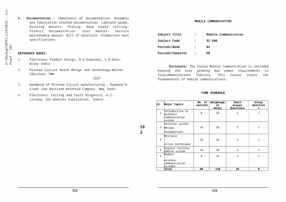
382 383
Understand Fibre Optic components and measuring instruments
List various fibre optic components
Mention the need for connectors in FOC
State the function of splice in optical fibres
List two types of connectors.
List two types of splices.
Distinguish between mechanical splice and fusion splice
Predict different losses occur due to improper splicing
State the need for optical coupler/splitter
List different optical couplers
Explain the working of an optical coupler
State the need for isolator in OFC
Explain the working of isolator.
List different types of measuring/testing instruments used in the field of OFC.
Explain the use of optical power meters
State the use of optical attenuators
Explain the working of Optical Time Domain Reflectometer (OTDR).
Know Fibre Optic Devices
List two types of sources used in OFC
Mention salient features of an optical source
List two types of detectors used in OFC
Mention important features of an optical detector
Explain the construction and working of an LED
State the principle of LASER.
Explain the construction and working of LASER source.
List the differences between LED and LASER sources
Explain the construction and working of PIN photo diode.
Explain the construction and working of APD (Reach through APD)
192
Explain the need for repeater/regenerator in FOC
List three types of repeaters
Compare R, 2R and 3R repeaters.
Distinguish between repeaters and optical amplifiers.
Draw the block diagram of Erbium Doped Fibre Amplifier (EDFA).
Explain the principle and operation of EDFA
Draw the block diagram of fibre optic communication system and explain each block.
List the other applications of LED and LASER
Understand Wavelength Division Multiplexing & Optical Networks
Define optical time domain multiplexing
Mention the limitations of time division multiplexing (OTDM) in FOC
Define wavelength division multiplexing.
Explain the need for WDM in fibre optic communication
List two types of WDM systems
Distinguish between wideband WDM and narrowband WDM (DWDM)
Draw the block diagram of WDM system
Draw and explain the block diagram of DWDM
List three types of network topologies
Explain bus, ring and star topologies used in fibre optic networks.
State the use of fibre optic cables in local area networks.
Explain the use of fibres in Ethernet and Gigabit Ethernet.
Explain the use of fibre optic cables for use in submarines.
Explain the use of fibres in local telephone and cable T.V (FTTH)
COURSE CONTENT
1.0 Basics of Fibre Optic Communication:
Advantages of Light wave communication system over EM wave systems.- Different optical spectral bands- Different generations of optical fibres- Structure of optical fibre-Classification of optical fibres based on refractive
D:\B
acku
p\S
BTE
T_C
14\D
EC
E -
1st P
roof
- 19
2

384 385
index profile- Types of fibres based on core diameter- Single mode fibre (SMF)- Multimode fibre (MMF)- Advantages of SMFs over MMfs- Snell’s law in optics- Total internal reflection in optical fibre- Acceptance angle- Define cone of acceptance- Numerical aperture (NA)- Expression for NA in terms of core and cladding refractive indices- Advantages of optical fibres over other communication media
2.0 Fibre manufacturing and cabling:
Types of fibre drawing processes- Outside Vapour Phase Oxidation (OVPO)method- Vapour phase Axial Deposition (VAD) method- Modified Chemical Vapour Deposition (MCVD) method- Plasma activated Chemical Vapour Deposition (PCVD) method- Different structural elements used for cable design- Types of fibre optic cables-Characteristics of loose buffered cable
characteristics of tight buffered cable- Various losses in optical fibres- Intrinsic and extrinsic losses-Classification of dispersions that occur in optical fibres- Group velocity dispersion- Inter modal and intra modal dispersion- Wave guide dispersion- Polarization mode dispersion
3.0. Fibre Optic components and measuring instruments:
Various fibre optic components- Need for connectors in FOC- Function of splice in optical fibres- Types of connectors- Types of splices- Mechanical splice and fusion splice- different losses occur due to improper splicing- Need for optical coupler/splitter- Different optical couplers- Working of an optical coupler- Need for isolator in OFC - Working of isolator.different types of measuring/testing instruments used in the field of OFC- Use of optical power meters- Use of optical attenuators- Working of Optical Time Domain Reflectometer (OTDR)
4.0. Fibre Optic Devices:
Types of sources used in OFC- Features of an optical source- Types of detectors used in OFC- important features of an optical detector- Construction and working of an LED- Principle of LASER- Construction and working of LASER source- Differences between LED and LASER sources- Construction and working of PIN photo diode- construction and working of APD (Reach through APD)- Need for repeater/regenerator in FOC- Types of repeaters-Compare R, 2R and 3R repeaters- comparison of repeaters and optical amplifiers- block diagram of Erbium Doped Fibre Amplifier (EDFA)- principle and operation of EDFA- Block
193
diagram of fibre optic communication system - Other applications of LED and LASER
5.0 Wavelength Division Multiplexing & Optical Networks:
Optical time domain multiplexing- Limitations of time division multiplexing (OTDM) in FOC- Wavelength division multiplexing- Need for WDM in fibre optic communication- Types of WDM systems- Wideband WDM and narrowband WDM (DWDM)- Block diagram of WDM system- Block diagram of DWDM- Types of network topologies- Bus, Ring and Star topologies used in fibre optic networks- Fibre optic cables in local area networks- Fibres in Ethernet and Gigabit Ethernet- Optic cables for use in submarines- Fibres in local telephone and cable T.V (FTTH)
REFERENCE BOOKS:
1. Optical Fiber Communications by Gerd Keiser McGraw Hill
2. Optical fiber and Laser- Principles and applications by Anuradha De, New Age publications
3. Optical fiber communications-Principles and practice, John M. Senior, Pearson Publications
4. Optical Fiber Communications and Its Applications – S.C.Gupta, 2004, PHI.
D:\B
acku
p\S
BTE
T_C
14\D
EC
E -
1st P
roof
- 19
3

386 387
COMPUTER HARDWARE
Subject Title : Computer Hardware
Subject Code : EC-604
Periods /Week : 04
Periods/Semester : 60
Rationale : Computer Hardware subject is included in the V semester as the understanding of computer and its associated hardware is rather a necessity for survival in the present situation. Units are designed to give a clear understanding of Computer Hardware including Operating system. The knowledge of computer hardware makes the students eligible for jobs computer industry also.
TIME SCHEDULE
Sl. Major Topics No. of periods
Weightage of marks
Short Answer
QuestionsEssay
Questions
1 Mother Board 16 26 2 2
2 ComputerPeripherals 12 26 2 2
3 Computeraccessories 12 16 2 1
4 Windows OS 10 26 2 2
5PC assembly & Software Installation
10 16 2 1
Total 60 110 10 8
OBJECTIVES
Upon completion of the course the student should be able to
Understand mother board and its features
Draw the layout of components in the motherboard.
List various expansion slots available on the motherboard.
List the details of different chipsets.
194
Explain the processor interface and specifications of processor.
List different types of MEMORIES used in PC.
Explain the use of accelerated graphics port.
List different power supply connectors used for external devices.
Mention different types of serial, parallel and USB ports.
Give 4 reasons for popularity of USB ports
Give the connector details for printer, serial port, mouse, keyboard and USB.
Comprehend the use of various computer peripherals
Explain the Working of Hard Disk and data access.
Explain the storage of data on DVD
Explain the functioning of GRAPHIC CARD.
Explain the functioning of Network card and list its specifications.
List five specifications of monitor.
Explain the working of LCD monitor.
Explain the working principle of Optical mouse.
Explain the working principle of wireless keyboard and mouse.
Understand the working of Computer Accessories
List three types of printers.
Explain the working of dot matrix printer.
Explain the working of Laser printer.
Explain the working of inkjet printer.
Compare the merits of above Printers
Mention the applications of 3D Printers
Explain the working of scanners.
Explain OCR (optical character recognition).
Explain the JPEG and MPEG formats.
Explain the principle of DVD and Writer.
D:\B
acku
p\S
BTE
T_C
14\D
EC
E -
1st P
roof
- 19
4
388 389
List out the features of a LAPTOP
Mention the differences between DESKTOP and LAPTOP.
List five features of TABLET(TAB)
List three features of FABLET
List out important features of TOUCH SCREEN for modern gadgets.
Understand the windows operating systems.
Define the Power On Self Test (POST).
Explain the need for BIOS settings.
Explain the booting procedure.
Explain the usage of File Allocation Table (FAT).
Explain the structure and uses of Windows registry
State the purpose of INI and INF files
List important device classes in the device manager.
Explain the purpose of control panel icons
List major types of viruses and ways of removing viruses.
List any five Anti-Virus Software available in market
Understand PC assembly and software installation
Explain the steps in assembling a PC.
Explain CMOS set up.
Explain the process of formatting.
Mention the use FDISK.
Explain the use of disk manager and disk partitioning
List important operating systems and their features.
Explain Installation of WINDOWS OS
Mention the uses of Linux OS and ANDROID OS
Explain the need for installation of device drivers.
Explain blocking, damaged sectors, Defragmentation, and Removal of temporary files.
195
List different microprocessors (INTEL, MOTORALA) used for PC applications
COURSE CONTENT
1.0 Mother board and its features:
Layout of components in the motherboard-Various expansion slots available on the motherboard-Details of different chipsets-Processor interface and specifications of processor-Types of MEMORIES used in PC-Use of accelerated graphics port-Different power supply connectors used for external devices-Types of serial, parallel and USB ports-Reasons for popularity of USB ports-Connector details for printer, serial port, mouse, keyboard and USB.
2.0 computer peripherals:
Working of Hard Disk and data access-Storage of data on DVD- Functioning of GRAPHIC CARD- Functioning of Network card- Specifications- Specifications of monitor- Working of LCD monitor- Working principle of Optical mouse- Working principle of wireless keyboard and mouse.
3.0. Computer Accessories
Types of printers-Working of dot matrix printer.- Working of Laser printer- Working of inkjet printer-Compare the merits of above Printers- Applications of 3D Printers- Working of scanners- OCR (optical character recognition)- JPEG and MPEG formats- Principle of DVD and DVD Writer- Features of a LAPTOP- Differences between DESKTOP and LAPTOP- Features of TABLET(TAB)-Features of FABLET-Important features of TOUCH SCREEN for modern gadgets.
4.0. Windows operating systems.
Power On Self Test (POST)- Need for BIOS settings- Booting procedure- File Allocation Table (FAT)- Structure and uses of Windows registry- Purpose of INI and INF files- Device classes in the device manager- Purpose of control panel icons- Types of viruses -Ways of removing viruses- Anti-Virus Software
D:\B
acku
p\S
BTE
T_C
14\D
EC
E -
1st P
roof
- 19
5

390 391
5.0 PC assembly and software installation
Steps in assembling a PC- CMOS set up- Process of formatting- Use of FDISK- Disk manager and disk partitioning- Operating systems and their features- Installation of WINDOWS OS - Uses of Linux OS and ANDROID OS- Need for installation of device drivers- blocking, damaged sectors, Defragmentation, and Removal of temporary files- Different microprocessors (INTEL, MOTORALA) used for PC applications.
ADVANCED MICRO CONTROLLERS & DSP
Subject title : Advanced Micro Controllers &
DSP Subject code : EC-605
Periods per week : 04
Periods / Semester : 60
REFERENCE BOOKS:
1. Peter Norton’s new inside the PC by Peter Norton, Scott Clark, PHI
2. Microprocessors, PC Hardware and interfacing by N. Mathivanan PHI
3. Trouble shooting your PC by M. David Stone and Alfred Poor,PHI
4. Enhanced guide to managing and maintaining your PC-Third Edition,Thomson IBM PC and CLONES - B.Govindrajalu Tata McGrawhill Publishers
5. Computer Installation and Servicing - D.Balasubramanian Tata McGraw Hill , 2005
6. Computer Installation and Troubleshooting- M.Radhakrishnan ISTE- Learning Materials 2001
7. The complete PC upgrade and Maintenance by Mark Minasi BPB Publication
196
Rationale: The course Advanced microcontrollers &DSP is introduced in the VI semester keeping in view the vast developments in the field of microcontrollers. This helps the students to get good job opportunities and have them an edge over others .
TIME SCHEDULE
Sl Major Topics Periods Weightage of Marks
Short Type Essay Type
1 PIC micro controllers 12 26 2 2
2Mcs-96 family 16 bit Microcontrollers
12 26 2 2
3 ARM micro controllers 12 26 2 2
4 DSP processor basics 15 16 2 1
5Embedded systems and RTOS basics
9 16 2 1
TOTAL 60 110 10 8
OBJECTIVES: On completion of the study of the subject a student should be able to comprehend the following:
Understand PIC Micro controller
Explain the RISC architecture
a. Explain the RISC Concept
b. Compare LIS and RISC Architecture
Mention the features of PIC controllers
D:\B
acku
p\S
BTE
T_C
14\D
EC
E -
1st P
roof
- 19
6

392 393
Compare PIC16F8XX and PIC16CX/7X families
Explain the block diagrams of ALU operations and PIC16F877
State the Features of PIC16F877
Discuss Architecture of PIC micro controller
Draw Memory and memory map of PIC microcontroller
Explain IO Ports
Explain Timers and CCP Modules
Explain Analogue to Digital Converter (ADC)
Explain Interrupts
Explain Addressing modes of PIC 16F877
Explain Instruction Set of PIC16F877
Explain interfacing of DC motor with PIC Microcontroller.
Understand MCS- 196 family 16 bit Microcontrollers
Bring out the salient features of MCS – 96 Microcontrollers
Draw and explain the block diagram of 80196 Microcontroller
Explain Internal Architecture of MCS – 96 Microcontrollers
Explain Memory Map of MCS – 96 Microcontrollers
Explain IO Ports and Timers of MCS-96 Microcontrollers
Explain High Speed Outputs and Inputs of MCS – 96 Microcontrollers
Explain Pulse Width Modulated Output of MCS – 96 Microcontrollers
Explain Interrupts of MCS – 96 Microcontrollers
Explain addressing Modes of MCS – 96 Microcontrollers
Explain Instruction set of MCS – 96 Microcontrollers
Understand ARM Microcontrollers
Explain the RISC Concept
Compare LIS and RISC Architecture
Explain ARM Core Architecture,
List 5 Important Features of ARM controller
197
Compare the Different versions of ARM controller
Explain Architecture of ARM controllers
Explain Memory Map of ARM controller
Explain Addressing Modes ARM controller
Explain Instruction set of ARM controller
Explain Arithmetic instructions
Explain Registersin ARM controllers.
Explain THUMB Instruction set Extensions of ARM controllers.
Explain the exception handling mechanism of ARM controllers.
Explain the concept of Pipelining in ARM processors controllers.
Mention four application of various versions of ARM controllers.
Understand DSP processor basics.
Explain the concept of Digital signal processing
Mention the merits of Digital signal processing over analog signal processing
Explain the use of digital filters in Digital signal processing.
Mention the applications of Digital signal processing.
Mention the 3 important signals used in Digital signal processing.
Draw the block diagram of a Digital system.
Mention the names of various blocks and their function..
Explain the function of anti-aliasing filter.
Mention the two types of Filters FIR and IIR used in digital signal processing
Compare FIR and IIR filters from the point of merits
Explain the differences between microprocessors and DSP processors
Distinguish between Offline processing and Real time processing
Explain the concept of circular buffer
Explain Multiplier and Multiplier Accumulator (MAC)
Give the IC numbers of the popular digital signal processors
List versions of TMS 320C5X family
D:\B
acku
p\S
BTE
T_C
14\D
EC
E -
1st P
roof
- 19
7

394 395
Comprehend Embedded System basics.
Explain Embedded System
Compare Embedded System and General Computing System
List five Application areas of Embedded System
Draw general block diagram of an embedded system
Explain Core of the Embedded System
Explain Memory management .
Explain Embedded Firm ware
Explain Communication Interface
Explain Operating System Basics
Explain Tasks, Process and Threads
Define Multi Processing and Multi Tasking
Explain Real Time Operating System
Compare Normal OS and RTOS.
List three Types of. RTOS
Explain basics of VXworks RTOS.
COURSE CONTENT
1. PIC Micro Controllers : RISC architecture-RISC Concept-Compare LIS and RISC Architecture-Features of PIC controllers-Compare PIC16F8XX and PIC16CX/7X families-Block diagrams of ALU operations and PIC16F877- Features of PIC16F877-Architecture of PIC micro controller- Memory and memory map of PIC microcontroller- IO Ports-Timers and CCP Modules- Analog to Digital Converter (ADC)-Interrupts-Addressing modes of PIC 16F877-Instruction Set of PIC16F877-Interfacing of DC motor with PIC Microcontroller.
2. MCS – 96 family 16 bit Microcontrollers:Salient features of MCS – 96 Microcontrollers-Block diagram of 80196 Microcontroller- Internal Architecture of MCS – 96 Microcontrollers- Memory Map of MCS – 96 Microcontrollers - IO Ports and Timers of MCS-96 Microcontrollers- High Speed Outputs and Inputs of MCS – 96 Microcontrollers- Pulse Width
198
Modulated Output of MCS – 96 Microcontrollers- Interrupts of MCS – 96 Microcontrollers- Addressing Modes of MCS – 96 Microcontrollers- Instruction set of MCS – 96 Microcontrollers-MCS family- MCS – 96 Microcontrollers-Important Features- Pin Diagram- Internal Architecture- Memory Map- Addressing Modes- Instruction set.
3. ARM Microcontrollers-RISC Concept-Compare LIS and RISC Architecture- ARM Core Architecture- Important Features of ARM controller-Compare the Different versions of ARM controller- Architecture of ARM controllers- Memory Map of ARM controller- Addressing Modes ARM controller- Instruction set of ARM controller- Arithmetic instructions- Registers of ARM Processors- THUMB-Instruction set Extensions of ARM- Exception handling mechanism of ARM-Concept of Pipelining in ARM processors-Application of various versions of ARM.
4. DSP Processor basics:Concept of Digital signal processing-Merits of Digital signal processing over analog signal processing-Use of digital filters in Digital signal processing-Applications of Digital signal processing-Important signals used in Digital signal processing-Block diagram of a Digital system-Names of various blocks and their function- Function of anti-aliasing filter-Types of Filters FIR and IIR used in digital signal processing-Compare FIR and IIR filters from the point of merits- Differences between microprocessors and DSP processors- Offline processing and Real time processing-Concept of circular buffer- Multiplier and Multiplier Accumulator (MAC)- IC numbers of the popular digital signal processors-Versions of TMS 320C5X family.
5. Embedded System and RTOS basics - Embedded System-Compare Embedded System and General Computing System- Application areas of Embedded System-Block diagram of an embedded system- Core of the Embedded System- Memory management- Embedded Firm ware- Communication Interface- Operating System Basics- Tasks, Process and Threads- Multi Processing and Multi Tasking- Real Time Operating System-Compare Normal OS and RTOS- Types of. RTOS-Explain basics of VXworks RTOS.
REFERENCE BOOKS:
1. Microcontroller Programming: The Microchip PIC By Julio Sanchez, Maria P. Canton CRC Press
2. PIC Microcontroller and Embedded Systems, Mazidi, McKinley and
D:\B
acku
p\S
BTE
T_C
14\D
EC
E -
1st P
roof
- 19
8

394 395
Danny Causey, Pearson Education, 2008

396 397
3. Advanced Microprocessor And Microcontrollers By B.P. Singh, New age International Publcations
4. Micro Processors and Micro Controllers- M.Senthil Kumar, M.Saravanan and S.Jeevanathan Oxford University Press, 1st Edn, 2010
5. DSP Processor Fundamentals, Architectures & Features – Lapsley et al. S. Chand & Co, 2000.
199
DIGITAL CIRCUIT DESIGN THROUGH VERILOG HDL
Subject title : Digital Circuit Design Through Verilog
HDL Subject code : EC-606
Periods per week : 04
Periods / Semester : 60
Rationale: The course Digital Circuit Design Through Verilog HDL is introduced in the VI semester keeping in view the vast developments in the field of VLSI Circuits. to helps the students get good job opportunities and have them an edge over others .
TIME SCHEDULE
Sl Major Topics Periods Weightage of Marks
Short Type
Essay Type
1 Basic Concepts of Verilog HDL
3 13 1 1
2Design flow for designing VLSI IC
10 16 2 1
3Gate Level, Data flow and Behavioral Modeling
16 16 2 1
4 Modeling of Combinational Logic Circuits
15 26 2 2
5 Verification and Testing of Verilog modules
10 26 2 2
6 System design concepts 6 13 1 1
TOTAL 60 110 10 8
OBJECTIVES: On completion of the study of the subject a student should be able to understand the following concepts.
I. Basic Concepts of VLSI Circuits
Explain the process MOS Transistor fabrication
D:\B
acku
p\S
BTE
T_C
14\D
EC
E -
1st P
roof
- 19
9

398 399
List the merits of CMOS technology
Explain CMOS fabrication process
List Layout design rules
Explain layout design rules
Explain stick diagrams Explain VLSI design flow
Explain VLSI design specification and design entry
Explain functional simulation
Explain Planning placement and Routing (PPR)
Explain timing simulation
Explain Fusing/Fabrication into the chip.
Explain the use of Verilog VHDL in VLSI simulation
2.0 Understand Design flow for designing VLSI IC and concepts of Verilog HDL
Explain the steps involved in the design flow for the VLSI IC design
Explain the importance of Hardware Description Languages in VLSI design
Compare VHDL and Verilog HDL
List the features of Verilog HDL
Explain the difference between an instantiation and inference of a component.
Explain differences between modules and module instances in Verilog.
Explain four levels of abstraction to represent the internals of a module
Identify the components of a Verilog module definition
Explain the port connection rules in a module instantiation
Explain the lexical conventions like number specification, Identifiers keywords, etc
Explain different data types like value set, nets, registers, vectors, integer, real and time register data types, arrays, memories and strings.
Explain defparam and localparam keywords
Explain about system tasks and compiler directives
Define expressions, operators and operands.
200
Explain all types of operators used in the Verilog HDL
3.0 Understand concepts of Gate level, Data Flow and Behavioral modeling
Identify the logic gate primitives provided in Verilog
Explain the instantiation of gates, gate symbols, and truth tables for and/ or and buf/not type gates.
Explain rise, fall and turn-off delays in the gate level design
Explain the initial and always statements.
Explain the assignment statements in data flow modeling
Explain different types of delays used in the data flow level modeling
Explain blocking and nonblocking procedural assignments with examples
Explain timing controls like delay based timing control and event based timing control.
Explain conditional statements.
Explain multiway branching - use case, casex and casez statements.
Explain the difference between conditional if statement and case statements.
Explain looping statements such as while, for, repeat, and forever.
Explain sequential and parallel blocks.
Explain User Defined Primitives(UDP)
Explain the hierarchical modeling,
List the advantages of hierarchical modeling
Explain modeling techniques in Verilog HDL.
Design simple logic circuits like adders, subtractors using Behavioral, Data
Flow and Structural modeling.
Understand Modeling of Combinational and Sequential Logic Circuits
Design combinational circuits like multiplexers, decoders, encoders, Comparators and ALU
D:\B
acku
p\S
BTE
T_C
14\D
EC
E -
1st P
roof
- 20
0
400 401
Design RS, JK, T and D flip flops with Asynchronous and Synchronous Clock and reset
Explain implementation of shift registers like SISO, SIPO, PISO, PIPO, etc.
Design synchronous and asynchronous counters
Design a divide by 3 counter
Design shift register counters like ring counter, etc.
Design memories like RAM and ROM.
Compare RTL level and structural level modelings.
Note: Use three levels of modelings (behavioral, dataflow and gate level) for the above designs.
List any 3 applications of above devices
Explain the design of UART using FPGA board
Explain the design of Traffic Light controller using FPGA board
COURSE CONTENT:
1. Basic Concepts of verilog HDL: MOS Transistor fabrication-Merits of CMOS technology- CMOS fabrication process-Layout design rules-Stick diagrams - VLSI design flow- VLSI design specification and design entry- Functional simulation-Planning placement and Routing (PPR)-Timing simulation- Fusing/Fabrication into the chip- Use of Verilog VHDL in VLSI simulation.
Apply Functional verification and Testing of Verilog modules.
Define test bench module.
Explain the need of a stimulus module.
Explain the structure of stimulus module.
Apply the stimulus modules for combinational and sequential circuits of Verilog designs.
Explain the concept of Finite State Machines.
Explain the Mealy and Moore types of State Machines.
Solve simple problems on Mealy and Moore state machines.
Explain the Design of Mealy above state machine using Verilog HDL.
Understand the system design concepts
Explain various design tools which are useful in different stages of design
List 4 important programmable logic devices
Explain the architecture of PLAs
Explain the architecture of PALs
Explain the architecture of CNLD
Explain the architecture of FPGAs,
Compare above devices
201
2. Design flow for designing VLSI IC : Steps involved in the design flow for the VLSI IC design-Importance of Hardware Description Languages in VLSI design-Compare VHDL and Verilog HDL-Features of Verilog HDL- Difference between an instantiation and inference of a component- Differences between modules and module instances in Verilog-Levels of abstraction to represent the internals of a module-Identify the components of a Verilog module definition-Port connection rules in a module instantiation-Lexical conventions like number specification, Identifiers keywords, etc-Different data types like value set, nets, registers, vectors, integer, real and time register data types, arrays, memories and strings-Defparam and localparam keywords-System tasks and compiler directives-Expressions, operators and operands-Types of operators used in the Verilog HDL.
3. Gate level, Data Flow and Behavioral modeling:Logic gate primitives provided in Verilog-Instantiation of gates, gate symbols, and truth tables for and/or and buf/not type gates-Rise, fall and turn-off delays in the gate level design-Initialand always statements- Assignment statements in data flow modeling-Different types of delays used in the data flow level modeling-Blocking and non-blocking procedural assignments with examples-Timing controls like delay based timing control and event based timing control-Conditional statements- Multiway branching - use case, casex and casez statements-Difference between conditional if statement and case statements-Looping statements such as while, for, repeat, and forever-Sequential and parallel blocks- User Defined Primitives(UDP)-Hierarchical modeling-Advantages of hierarchical modeling-Modeling techniques in Verilog HDL-Design simple logic
D:\B
acku
p\S
BTE
T_C
14\D
EC
E -
1st P
roof
- 20
1
402 403
circuits like adders, subtractors using Behavioral, Data-Flow and Structural modeling. COMPUTER HARDWARE , NETWORKING & O FCLAB PRACTICE
4. Modeling of Combinatioal Logic Circuits Modeling of Combinatioal and Sequential Circuits-Design combinational circuits like multiplexers, decoders, encoders, Comparators and ALU-Design RS, JK, T and D flip flops with Asynchronous and Synchronous Clock and reset-Explain implementation of shift registers like SISO, SIPO, PISO, PIPO, etc-Design synchronous and asynchronous counters-Design a divide by 3 counter- Design shift register counters like ring counter, etc-Design memories like RAM and ROM-Compare RTL level and structural level modelings.
5. Verification and Testing of Verilog modules:Test bench module- Need of a stimulus module-Structure of stimulus module-Stimulus modules for combinational and sequential circuits of Verilog designs-Concept of Finite State Machines- Mealy and Moore types of State Machines- Problems on Mealy and Moore state machines- Design of Mealy above state machine using Verilog HDL.
6. System design concepts:Various design tools which are useful in different stages of design-Important programmable logic devices- Architecture of PLAs-Architecture of PALs-Architecture of CNLD- Architecture of FPGAs-Comparison-Applications-Design of UART using FPGA board-Design of Traffic Light controller using FPGA board.
REFERENCE BOOKS:
1. Digital Design with an Introduction to Verilog HDL 5th Edition by M. Morris Mano and Michael Ciletti –Pearson publishers
2. Verilog HDL: A guide to digital design and synthesis by S. Palnitkar- Prentice Hall PTR Publishers
3. Design through Verilog HDL – T.R. Padmanabhan and B. Bala Tripura Sundari, WSE, IEEE Press, 2004.
4. Fundamentals of Logic Design with Verilog – Stephen. Brown and Zvonko Vranesic, TMH, 2005.
202
Subject Title : Computer Hardware , Networking & OFCLab Practice .
Subject Code : EC-607
Periods/Week : 06
Periods/Semester : 90
Rationale: With the computer becoming a household item , the need for Computer hardware knowledge need not be stressed. Computer hardware industry is another major area where excellent job opportunities are available. Experiments in Optical fibre communication are also included to give additional practical inputs.
S. No.TIME SCHEDULE
PRACTICE No. of Periods
1. Computer System(Desktop,Laptop) 45
2. Computer Peripherals 6
3. Networking 27
4 Fibre Optics 12
Total 90
List of Experiments
1.0 PC Hardware-Identification of System Layout.
1. Identify Basic Computer Hardware and Cables
2. Identify and note down mother board , Components and Chips
3. Identify various Internal and External slots in the mother board and clean them with blower/ Brush.
4. Practice Inserting and Removing RAM with care
D:\B
acku
p\S
BTE
T_C
14\D
EC
E -
1st P
roof
- 20
2
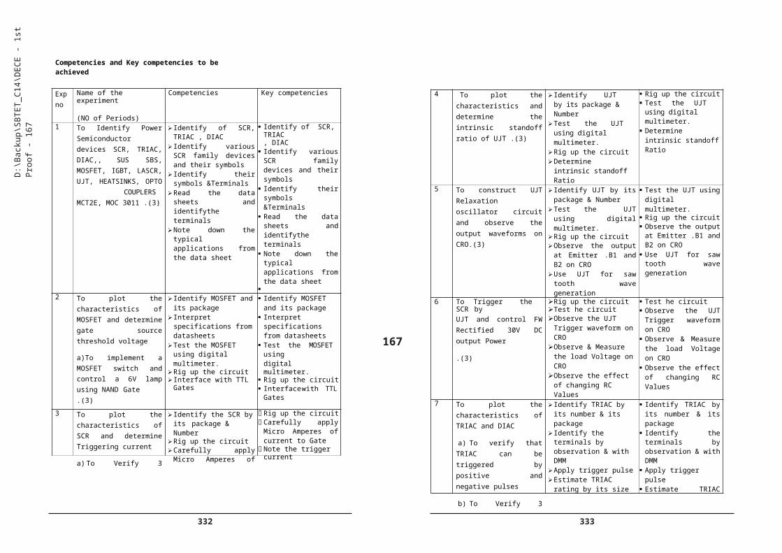
404 405
5. Measure the Output voltages of SMPS
6. Disassemble the PC
7. Assemble the PC and test
8. Change CMOS Setup
9. Install Operating system Windows and Linux
10. Verify the function of control panel settings.
11. Partition and format Hard disks.
12. Install system and application software
a) To install & Run antivirus software
13. Carry out Preventive maintenance of a PC
14. Take Backup of C drive
15. Identify Laptop Hardware
16. Carry out PC Troubleshooting
2.0 Printers , Scanners, Cameras
17. Connect , operate and maintain i) Inkjet Printer ii) Laser Printer iii)Scanneriv) Web Cam
3. Computer Networking
18. identify and note down the specifications of various networking devices & Cables, Jacks , Connectors, tools etc used in local area networks aPrepare the UTP cable for cross and direct connections using crimping tool.
19. Transfer files between systems in LAN using FTP Configuration,
a) install i Print server in a LAN and share the printer in a network
20. Test the Network using ipconfig, ping / tracert and Netstat utilities and debug the network issues (3)
21. Install and configure Network Devices: HUB ii) Switch iii) Routers
22. Configure Host IP, Subnet Mask and Default Gateway in a system in LAN (TCP/IP Configuration).
a) Configure DNS to establish interconnection between systems
23. Transfer files between systems in LAN using FTP Configuration,
a) install Print server in a LAN and share the printer in a network
203
24. Install and Configure Wireless NIC and transfer files between systems in LAN and Wireless LAN
25. access a remote desktop using Team viewer software
a) store the files in Cloud using Google drive/One drive/Drop box & share
26. Explore the features of Windows 2000 server
4.0 Fiber Optics
27. Set up fiber optic analogue link.
a) Set up a fiber optic digital link
28. Verify modulation & Demodulation of light source by pulse width modulation technique.
29. Test Fiber optic Voice Link.
30. Verify the NRZ & RZ modulation formats in Optical Communication.
D:\B
acku
p\S
BTE
T_C
14\D
EC
E -
1st P
roof
- 20
3

406 407
Competencies and Key Competencies to be achieved
204
D:\B
acku
p\S
BTE
T_C
14\D
EC
E -
1st P
roof
- 20
4
3 To Identify various Internal and External slots in the mother board and clean them withblower/ Brush.(11)
2
Internal : Identify PCI Express 16x slots
PCI Express 1x Slot DIMM (Double Inline
Memory Module) slots Serial ATA Connector
south Bridge IDE connector PCI (Peripheral
Component Interconnect) slot
BIOS (Basic Input Output System) Chip
External : Identify Bus) PortsPS/2
Connectors - USB (Universal Serial - Parallel Port -Game Port
Sound card Connectors
Display VGA Connector
COM (communications) Port
PCI Express 16x slots PCI Express 1x Slot
DIMM (Double Inline Memory Module) slots
Serial ATA Connector south Bridge
IDE connector PCI (Peripheral
Component Interconnect) slot
BIOS (Basic Input Output System) Chip
External :Identify Bus) PortsPS/2
Connectors - USB (Universal Serial - Parallel Port -Game Port
Sound card Connectors
Display VGA Connector
COM(communications) Port
4 To Practice Inserting andRemoving RAM with care(11)
2
Identify the RAM type SRAM ,DDR ,DDR2 DDR3 by observing the notch
Place DIMM with correct orientation
Insert with correct force till it is locked
Test by slightly pulling
Remove DIMM by opening latches on either side
Identify the RAM type SRAM ,DDR,DDR2 DDR3 byobserving the notch
Place DIMM with correct orientation
Insert with correct force till it is locked
Test by slightly pulling
Remove DIMM by
opening latches on
either side
5 To measure the Outputvoltages of SMPS (11)
2
Remove the SMPS Identify the ground
Short the enable pin to groundMeasure the output voltages with DMM
Identify the ground Short the enable pin
to ground Measure the output
voltages with DMM
Exp No
Name of the Experiment Competencies Key Competencies
1 To Identify Basic Computer Identify Configure bios setup program andtroubleshoot the typical problems using BIOS utility.
Hardware and Cables (3) Key board , Mouse, Webcam
Front panel indicators switches
Front side & rear side connectors. Ports
Mark positions of SMPS, Motherboard, FDD, HDD, CD, DVD and add on cards.
Power cable, VGAcable, Audio cable
2 To Identify and note downmother board , Components
Mother Board installation
Note the layout of I5/I3/Pentium IV or Pentium Dual core or Pentium Core2 DUO mother board and mark Processor,
Identify Chip set ICs. RAM, Cache, Xtal, CMOS Battery
Identify CPU cooling fan, I/O slots and I/O ports and various jumper settings.
ATX Power connector
CPU (Central Processing Unit) socket
and Chips (1 ) Note the layout of I5/I3/Pentium IV or Pentium Dual core or Pentium Core2 DUO mother board and mark Processor,
Identify Chip set ICs. RAM, Cache, Xtal, CMOS Battery
Identify CPU cooling fan, I/O slots and I/O ports and various jumper settings.
ATX Power connector
CPU (Central Processing Unit) socket

408 409
205D:\B
acku
p\S
BTE
T_C
14\D
EC
E -
1st P
roof
- 20
5 10 To Verify the function of control
panel settings (1 ).
To verify and Explore control panel features
System & Security Network& Internet
Hardware & Sound Programs User Accounts Appearance Clock Access device
manager and check the status
Add or remove hardware devices
To verify and Explore control panel features
System & Security Network& Internet
Hardware & Sound Programs User Accounts Appearance Clock Access device
manager and check the status
Add or remove hardware devices
11 To Partition and format Hard disks(1 )
Identify HDD Type IDE/SATA
Follow respective procedures
Select NTFS/FAT32 Backup file Use Windows/
Startup CD Use Disk manger
Identify HDD Type IDE/SATA
Follow respective procedures
Select NTFS/FAT32Backup fileUse Windows/ Startup
CD Use Disk manger
12 To Install system and application software (3)a) To install & Run antivirus software
Access control panel Install/Uninstall the
program Install antivirus
through auto run option
Explore the antivirus settings
Access control panel Install/Uninstall the
program Install antivirus
through auto run option
Explore the antivirus settings
13 To Carry out Preventive maintenance of a PC(3)
Clean C Scan with antivirus Run Registry clean
utility Run Defragmentation
Clean C Scan with antivirus Run Registry clean
utility Run
Defragmentation14 To take Backup of C drive (3) Take Backup of C
Drive using Backup utility
Take Backup of C drive using Backup utility
15 To identify Laptop Hardware(3)
Identify the Parts of a Laptop - CPU, Display- HDD, DVD drive - USB Ports HDMI-VGA-Ethernet-SDCard
Identify the Parts of a Laptop - CPU, Display- HDD, DVD drive - USB Ports HDMI-VGA-Ethernet-SD Card
6 To disassemble the PC (3) Remove Power cable ,USB,
Firewire, Mouse, Keyboard Internet, Ethernet ,Modem cables
Remove the rear cabinet
screws ,side panel Remove Mother
board power cable & Other cables
Remove SMPS, CD/DVD drive, HDD
Remove mother Board
Remove Powercable, USB,Firewire, Mouse, Keyboard Internet, Ethernet ,Modem cables
Remove the rear cabinet
screws ,side panel Remove Mother
board power cable & Other cables
Remove SMPS, CD/DVD drive, HDD
Remove mother Board
7 To assemble the PC and test (3)
Install PSU DVD Mother Board
Processor heat sink &Fan memory –
Connect HDD Clear CMOS by
removing jumper Connect power
connector, CPU power connector and other connector
Connect case fan to mother board
Connect sata cables Test connections Fix side panels
Install PSU DVD Mother Board
Processor heat sink &Fan memory
HDD Clear CMOS by
removing jumper Connect power
connector, CPU power connector and other connector
Connect case fan to mother board
Connect sata cables Test connections Fix side panels
8 To change CMOS Setup(3) Identify manufacturer Open cmos setup Change the boot
sequence Enable disable
devices/Ports set pass word
change Date/Time Explore other
features
Identify manufacturer
Open cmos setup Changeboot
sequence Enable disable
devices/Ports set pass word
change Date/Time Explore other features
9 To Install Operating system Windows and Linux (6)
Install OS using CD Set up Disk
partitioning Install drivers
Install OS using CD Set up Disk
partitioning Install drivers
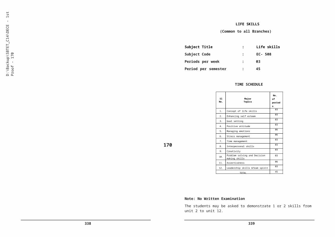
410 411
206
D:\B
acku
p\S
BTE
T_C
14\D
EC
E -
1st P
roof
- 20
6
16 To carry out PC Troubleshooting(6)
Identify the fault type Hardware/ software Run antivirus and
other utilities Run in safe mode Rectify the problemHardware faults Faulty cables Dust accumulation Monitor problems Memory problems SMPS problems HDD/CD/ problems Troubleshoot
&Rectify
Identify the fault type Hardware/ software
Run antivirus and other utilities
Run in safe mode Rectify the problem Hardware faults Faulty cables Dust accumulation Monitor problems Memory problems SMPS problems HDD/CD/ problems Troubleshoot
&Rectify
17 To connect , Operate and maintain (6)i) Inkjet Printerii) Laser Printer
iii)Scanneriv) Webcam
Connect and operate Printers
Remove paper jams Load ink Cartridge
Connect to network Use scanner Use webcam
Connect and operate Printers
Remove paper jams Load ink Cartridge
Connect to Network Use scanner Use webcam
18 To identify and note down the specifications of various networking devices & Cables, Jacks , Connectors, tools etc used in local area networks (3)
a) To Prepare the UTP cable for cross and direct connections using crimping tool.
Identify & note down the configurations of Network devices
Identify & Select Network cable
Select crimping tool Select the cable
Decide the connection type
Identify the wires as per colour code
Arrange the wires Cut & Crimp Test the connection
using Pingcommand
Identify & note down the configurations of Network devices
Identify & Select Network cable
Select crimping tool Select the cable Decide the
connection type Identify the wires as
per colour code Arrange the wires Cut & Crimp Test the connection
19 To Transfer files between systems in LAN using FTP Configuration (3)
a) To install Print server in a LAN and share the printer in a network
Transfer files between systems in LAN using FTP Configuration,
install Print server in a LAN and share theprinter in a network
Transfer files between systems in LAN using FTP Configuration,
install Print server in a LAN and share the printer in a network
20 To Test the Network using ipconfig, ping / tracert and Netstat utilities and debug the network issues(3)
Use the Utilities like ipconfig, ping / tracert
Identify the issue Resolve the problem
Use the Utilities like ipconfig, ping / tracert
Identify the issue Resolve the problem
21 To Connect systems in a network using switch. (3)a) Install and configure Network Devices:i) Hub ii) Switch iii) Routers
Select the device Connect them Install using Driver
software Set password & Configure
Select the device Connect them Install using Driver
software Set password & Configure
22 To Configure Host IP, Subnet Mask and Default Gateway in a system in LAN (TCP/IP Configuration).(3)
a) To Configure DNS to establish interconnectionbetween systems
Configure Host IP, Subnet Mask
Configure DNS server
Configure Host IP, Subnet Mask
Configure DNS server
23 To Transfer files between systems in LAN using FTP Configuration, (3)
a) install Print server in a LAN and share the printer in anetwork
Open control panel Access IIS Set up FTP and
Test Share the printer
Open control panel Access IIS Set up FTP and
Test Share the printer
24 To Install and Configure Wireless NIC and transfer files between systems in LAN andWireless LAN(3)
Install wireless NIC Configure Set pass word Test
Install wireless NIC Configure Set pass word Test
25 To access a remote desktop using Team viewer software(3)a) To store the files in Cloud using Google drive/One drive/Drop box & share
Install Team viewersoftware
Start the session Access desktop
remotely Video chat Close the session Use Google drive
/One drive/Drop box & share
Install Team viewer software
Start the session Access desktop
remotely Video chat Close the session Use Google drive /One drive/Drop box
& share26 To Explore the features of
Windows 2000 server(3) Use administrative
tools Configure server for
Network connectivity Sharing a folder Accessing a folder
from my network places on Desktop
Stopping a shared folder
Determine local host address
Use administrative tools
Configure server for Network connectivity
Sharing a folder Accessing a folder
from my network places on Desktop
Stopping a shared folder
Determine local host address
412 413
VERILOG HDL LAB PRACTICE
Subject title : Verilog HDL Programming lab
Practice Subject code : EC-608
Periods per week : 03
Periods / Semester : 45
Rationale: This laboratory course is Included to reinforce and practically verify the theoretical inputs learnt in the theory part of this semester without losing the contiguity. Further this course also helps the students to experiment with latest tools used in the VLSI Circuit design which gives the students an edge over others .
TIME SCHEDULE
207
List of Experiments:
Using Xilinx / Modelsim / Multisim or similar software
1. Practicewith MultiSIm simulation software for verilog HDL
2. Implement Basic Logic Gates
3. Implement i) Half adder and ii) Full Adder
4. Implement i) Half Subtractor and ii) Full Subtractor
5. Implement 4-bit Parallel Adder
D:\B
acku
p\S
BTE
T_C
14\D
EC
E -
1st P
roof
- 20
7
27 To Set up fibre optic analogue link.
a)To Set up a fibre optic digital link (3)
Identify the Demonstration board, Fiber optic link & Connectors
Make connections Test and observe
the signal on CRO
Make connections Test and observe
the signal on CRO
28 To verify modulation & Demodulation of light source by pulse width modulation technique. (3)
Identify the Demonstration board
Fiber optic link & ConnectorsMake connections Test and observe the signal on CRO
Make connections Test and observe
the signal on CRO
29 To Test Fibre optic Voice Link. (3)
Identify the Transmitter & Receiver boards,Fiber optic link & Connectors, Microphone
Make connections Test and listen to the
voice signal Observe any
distortion
Make connections Test and listen to the
voice signal Observe any
distortion
30 To Verify the NRZ & RZ modulation formats in Optical Communication.(3)
Identify the Demonstration board Fiber optic link & Connectors
Make connections Apply digital signal Test and observe
the signal on CRO
Make connections Apply digital signal Test and observe
the signal on CRO
Sl No Major Topics Periods
1 Implementing basic logic gates 6
2 Combinational circuits 12
3 Sequential circuits 12
4 Registers 9
5 Counters 6
TOTAL 45
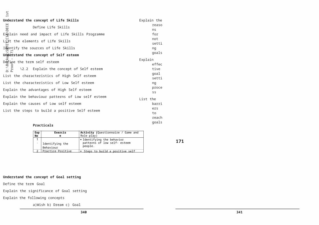
414 415
6. Implement 4:1 Multiplexers
7. Implement 1:4 Demultiplexers
8. Implement 3:8 Decoders
9. Implement 8:3 Encoders
10. Implement 4-bit Comparator
11. Implement SR-Flip flop
12. Implement) JK- Flip Flop
13. Implement D- Flip Flop)
14. Implement i) SISO ii) SIPO Shift Registers
15. Implement a Decimal counter
208
Competencies and Key Competencies to be achieved
D:\B
acku
p\S
BTE
T_C
14\D
EC
E -
1st P
roof
- 20
8
Exp no
Name of the experiment
(NO of Periods)
Competencies Key competencies
1 To practice with
Xilinx/ ModelSim/MultiSim simulation software for verilog HDL (3)
Familiarize with Xilinx/ ModelSim /MultiSimInterface
Create a directory for the project
Start ModelSim and create a new project
Enter the codeAdd verilog file to the
project Compile your verilog files Start the simulationAdd signals to the wave
window Recompile changed
verilog files Restart/Run the
simulation
Familiarize with Xilinx/ ModelSim /MultiSimInterface
Create a directory for the project
Start ModelSim and create a new project
Enter the code Add verilog file to the
project Compile your verilog
files Start the simulation Add signals to the wave
window Recompile changed
verilog files Restart/Run the
simulation2 To implement Basic Logic
Gates (3)Create a directory for the
project Start ModelSim and
create a new project Enter the codeAdd verilog file to the
project Compile your verilog files Start the simulationAdd signals to the wave
window Recompile changed
verilog files Restart/Run the
simulation
Create a directory for the project
Start ModelSim and create a new project
Enter the code Add verilog file to the
project Compile your verilog
files Start the simulation Add signals to the wave
window Recompile changed
verilog files Restart/Run the
simulation3 To implement
i) Half adder and ii) Full Adder (3)
Design the logic Enter the codeAdd verilog file to the
project Compile your verilog files Start the simulationAdd signals to the wave
window Recompile changed
verilog files
Design the logic Enter the code Add verilog file to the
project Compile your verilog
files Start the simulation Add signals to the wave
window Recompile changed
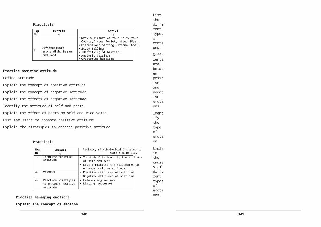
416 417
209
Note : Implement gate level modeling
Tools Required:
Xilinx ISE 9.2i simulator and Modelsim /MultiSimSoftware
D:\B
acku
p\S
BTE
T_C
14\D
EC
E -
1st P
roof
- 20
9
4 To implement
i) Half Subtractor and
ii) Full Subtractor (3)
Design the logicEnter the codeAdd verilog file to the
projectCompile your verilog filessimulate
Design the logic Enter the code Add verilog file to the
project Compile your verilog
files simulate
5 To implement 4-bit Parallel Adder (3)
Design the logicEnter the codeAdd verilog file to the
projectCompile your verilog filessimulate
Design the logic Enter the code Add verilog file to the
project Compile your verilog
files simulate
6 To implement 4:1Multiplexers (3)
Design the logicEnter the codeAdd verilog file to the
projectCompile your verilog filessimulate
Design the logic Enter the code Add verilog file to the
project Compile your verilog
files simulate
7 To implement 1:8 De- multiplexer (3)
Design the logicEnter the codeAdd verilog file to the
projectCompile your verilog filessimulate
Design the logic Enter the code Add verilog file to the
project Compile your verilog
files simulate
8 To implement 3:8 Decoder(3)
Design the logicEnter the codeAdd verilog file to the
projectCompile your verilog filessimulate
Design the logic Enter the code Add verilog file to the
project Compile your verilog
files simulate
9 To implement 8:3 Encoder(3)
Design the logicEnter the codeAdd verilog file to the
projectCompile your verilog filessimulate
Design the logic Enter the code Add verilog file to the
project Compile your verilog
files
10 To implement 4-bit Comparator (3)
Design the logicEnter the codeAdd verilog file to the
projectCompile your verilog filessimulate
Design the logic Enter the code Add verilog file to the
project Compile your verilog
files simulate
11 To implement SR-Flip flop
(3)
Design the logicEnter the codeAdd verilog file to the
projectCompile your verilog filessimulate
Design the logic Enter the code Add verilog file to the
project Compile your verilog
files simulate
12 To implement JK Flip Flop(3)
Design the logicEnter the codeAdd verilog file to the
projectCompile your verilog filessimulate
Design the logic Enter the code Add verilog file to the
project Compile your verilog
files simulate
13 To implement D Flip Flop(3)
Design the logicEnter the codeAdd verilog file to the
projectCompile your verilog filessimulate
Design the logic Enter the code Add verilog file to the
project Compile your verilog
files simulate
14 To implement i) SISO
ii) SIPO Shift Register (3)
Design the logicEnter the codeAdd verilog file to the
projectCompile your verilog filessimulate
Design the logic Enter the code Add verilog file to the
project Compile your verilog
files simulate
15 To implement a Decimal counter (3)
Design the logicEnter the codeAdd verilog file to the
projectCompile your verilog filessimulate
Design the logic Enter the code Add verilog file to the
project Compile your verilog
files simulate

418 419
ADVANCED MICRO CONTROLLERS LAB PRACTICE
Subject title : Advanced Micro Controllers Lab Practice
Subject code : EC-609
Periods per week : 3
Periods / Semester : 45
Rationale: This laboratory course is Included to reinforce and practically verify the theoretical inputs learnt in the theory part of this semester without losing the contiguity. Further this course also helps the students to experiment with Advanced Microcontrollers like ARM which gives the students an edge over others and better employment opportunities.
TIME SCHEDULE
Sl Major Topics Periods
1 Programming PIC Controller for data processing
12
2 Interfacing DAC 9
3 Interfacing Sensors & ADC 12
4 Programming ARM Controllers
12
TOTAL 45
LIST OF EXPERIMENTS
1. Write a C Program for PIC16F877 to add two 16-bit operands
2. Write a C Program for PIC16F877 to add two 32-bit operands
3. Write a C Program for PIC16F877 to subtract two 16-bit operands
4. Write a C Program for PIC16F877 to multiply two operands
210
5. Write a C Program to generate a Square wave by interfacing 8-bit bipolar DAC with PIC16F877
6. Write a C Program to generate a Sine wave by interfacing 8-bit bipolar DAC with PIC16F877
7. Write a C Program to interface ADC module with PIC16F877
8. Write a C Program to generate PWM by interfacing ADC module with PIC16F877
9. Write a C Program to design a digital thermometer to display the temperature in 0C using PIC16C71
10. Write a C Program to design a LVDT interfacing with PIC16C71 using AD698
11. Write a C Program to add two 16-bit operands using ARM controller
12. Write a C Program to add two 32-bit operands using ARM controller
13. Write a C Program to subtract two 16-bit operands using ARM controller
14. Write a C Program to multiply two operands using ARM controller
15. Write a C Program to generate a triangular wave using the ARM Controller
D:\B
acku
p\S
BTE
T_C
14\D
EC
E -
1st P
roof
- 21
0

420 421
Competencies and Key Competencies to be achieved
211
D:\B
acku
p\S
BTE
T_C
14\D
EC
E -
1st P
roof
- 21
1
8 Write aC program to generate PWM by interfacing ADC module with PIC16F877
Enter the Program in Editor
RIG Up The Circuit Compile and Execute
Enter the Program in Editor
Compile and Execute Verify the
Result
9 Write aC program to design
a digital thermometer to
display the temperature in 0C using PIC16C71 and
Digital Display Unit
Enter the Program in Editor
RIG Up The Circuit Compile and Execute
Enter the Program in Editor
Compile and Execute Verify the
Result
10 Write aC program to design
a LVDT interfacing with
PIC16C71 using AD698.
And observe the readings
on Digital Display Unit
Enter the Program in Editor
Rig up the circuit
Compute and Execute
Enter the Program in Editor
Compile and Execute Verify the
Result
11 Write aC program to add
two 16-bit operands using
ARM controller
Enter the Program in Editor
Compile and Execute Verify the Result
Enter the Program in Editor
Compile and Execute Verify the
Result
12 Write aC program to add
two 32-bit operands using
ARM controller
Enter the Program in Editor
Compile and Execute Verify the Result
Enter the Program in Editor
Compile and Execute Verify the
Result
13 Write aC program to
subtract two 16-bit
operands using ARM
controller
Enter the Program in Editor
Compile and Execute Verify the Result
Enter the Program in Editor
Compile and Execute Verify the
Result
14 Write aC program to
multiply two operands using
ARM controller
Enter the Program in Editor
Compile and Execute Verify the Result
Enter the Program in Editor
Compile and Execute Verify the
Result
15 .Write a C Program to
generate a triangular
WAVE using the ARM
Controller
Enter the Program in Editor
Compile and Execute Observe the
Waveform using CRO
Enter the Program in Editor
Compile and ExecuteVerify the Result
Exp No
Name of the Experiment Competencies Key Competencies
1 Write a C PROGRAM FOR
PIC16F877to add two 16-
bit operands
Enter the Program in Editor
Compile and Execute Verify the Result
Enter the Program in Editor
Compile and Execute Verify the
Result
2 Write a C PROGRAM FOR
PIC16F877to add two 32-
bit operands3.
Enter the Program in Editor
Compile and Execute Verify the Result
Enter the Program in Editor
Compile and Execute Verify the
Result3 Write a C PROGRAM FOR
PIC16F877to subtract two
16-bit operands
Enter the Program in Editor
Compile and Execute Verify the Result
Enter the Program in Editor
Compile and Execute Verify the
Result
4 Write a C PROGRAM FOR
PIC16F877to multiply two
operands
Enter the Program in Editor
Compile and Execute Verify the Result
Enter the Program in Editor
Compile and Execute Verify the
Result
5 Write a C PROGRAM to
generate a Square wave by
interfacing 8-bit bipolar
DAC with PIC16F877
Enter the Program in Editor
Compile and Execute Observe the
Waveform using CRO
Enter the Program in Editor
Compile and Execute Verify the
Result
6 Write a C PROGRAM to
generate a Sine wave by
interfacing 8-bit bipolar
DAC with PIC16F877
Enter the Program in Editor
Compile and Execute Observe the
Waveform using CRO
Enter the Program in Editor
Compile and Execute Verify the
Result
7 Write a C PROGRAM to
interface ADC module with
PIC16F877 .Use a Variable
Analog TEST Signal
Observe the readings on
Digital Display Interface
Enter the Program in Editor
Compile and Execute Tabulate the readings
Enter the Program in Editor
Compile and Execute Verify the
Result

422 42
PROJECT WORK
Subject Title : Project Work
Subject Code : EC- 610
Periods / Week : 06
Periods / Semester : 90
Rationale:Project work is intended to provide application level concepts in designing and Implementing suitable solutions to multifarious needs related to Industry as well as Day to day Life . Project work should pave way for i) implementation of Innovative Ideas ii) preparation of prototypes for commercial models.
TIME SCHEDULESl Major Topics Periods
1 Literature survey 9
2 Concept modelling 9
3Seminars( One Seminar before approval and one Seminar after completion of the Project)
6
4 Abstract submission 6
5 Working model of the project 45
6 Project report 15
Total 90
Project work should have the following components
1. Literature survey
2. Concept modelling
212
3. Seminars( One Seminar before approval and one Seminar after completion of the Project)
4. Abstract submission
5. Working model of the project
6. Project report
OBJECTIVES
Upon completion of the course the student should be able to
Identify different works to be carried out in the Project.
Collect relevant information required for the project work.
Carry out Literature survey.
Select the most efficient method from the available choices based on preliminary investigation.
Prepare action plan and schedule for project implementation
Design the required elements of the project work as per standard practices.
Implement prototype circuits and test
Design proper enclosure to house the prototype
Identify the Tests to be carried out for verification of design parameters
implement project work and record the results at various stages.
Prepare project report as per the standard guide lines.
COURSE CONTENT
Project work is intended to provide application level concepts in designing and Implementing suitable solutions to multifarious needs related to Industry as well as Day to day Life .
Project work should pave way for
i) implementation of Innovative Ideas
ii) preparation of prototypes for commercial models.
D:\B
acku
p\S
BTE
T_C
14\D
EC
E -
1st P
roof
- 21
2
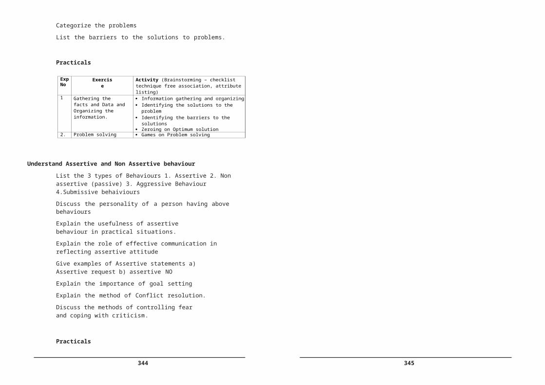
42
Students should be formed into groups of five each and shall be assigned a problem that calls for application of the knowledge he/she acquired during the course .The faculty members shall provide necessary and also monitor /assess the project progress. The students may be encouraged to implement projects using Aurdino boards / Picaxe / ARM Controllers in the fields of Communication Engineering, Industrial electronics ,Robotics or any other relevant fields. Preparing a working model complete in all respects including proper enclosure, indicators switches, Power cords etc is mandatory.
Every student should prepare a project report and submit the same for assessment which includes his/her contribution in the project work . The end examination in Project work shall consist of Seminar and Viva- voce test to be assessed by a panel of examiners comprising of an External examiner, the Head of Section, and the internal guide.
Other interested faculty members and students may also be invited for attending the seminars.
Scheme of assessment
1) Seminar1 10 Marks
2) Seminar 2 10 Marks
3) Project Report/Assessment 20 Marks
4) Project 40 Marks
5) Viva-Voce 20 Marks——————
Total Marks 100
213
D:\B
acku
p\S
BTE
T_C
14\D
EC
E -
1st P
roof
- 21
3