· web viewbanjul accord group aviation safety oversight organisation (bagasoo) generic part xxx...
TRANSCRIPT

BANJUL ACCORD GROUP AVIATION SAFETY OVERSIGHT ORGANISATION
(BAGASOO)
GENERIC PART XXX MANUAL OF AERODROME STANDARDS
A generic Manual produced for the use of BAG Member States in the establishment of standards on aerodrome design and
operations.
This manual is based on ICAO Annex 14, Fifth Edition incorporating amendment 10-B, November 2009.
NOVEMBER, 2012
Manual Of Aerodrome Standards (State) Civil Aviation Authority
XXXX CIVIL AVIATION AUTHORITY
PART XX MANUAL OF AERODROME STANDARDS
Issue 00: Jan. 2013 2

Manual Of Aerodrome Standards (State) Civil Aviation Authority
LEFT BLANK INTENTIONALLY
Issue 00: Jan. 2013 3

Manual Of Aerodrome Standards (State) Civil Aviation Authority
RECORD OF AMENDMENTS
AMENDMENTS
No. Date issued Date Entered Entered by Organization
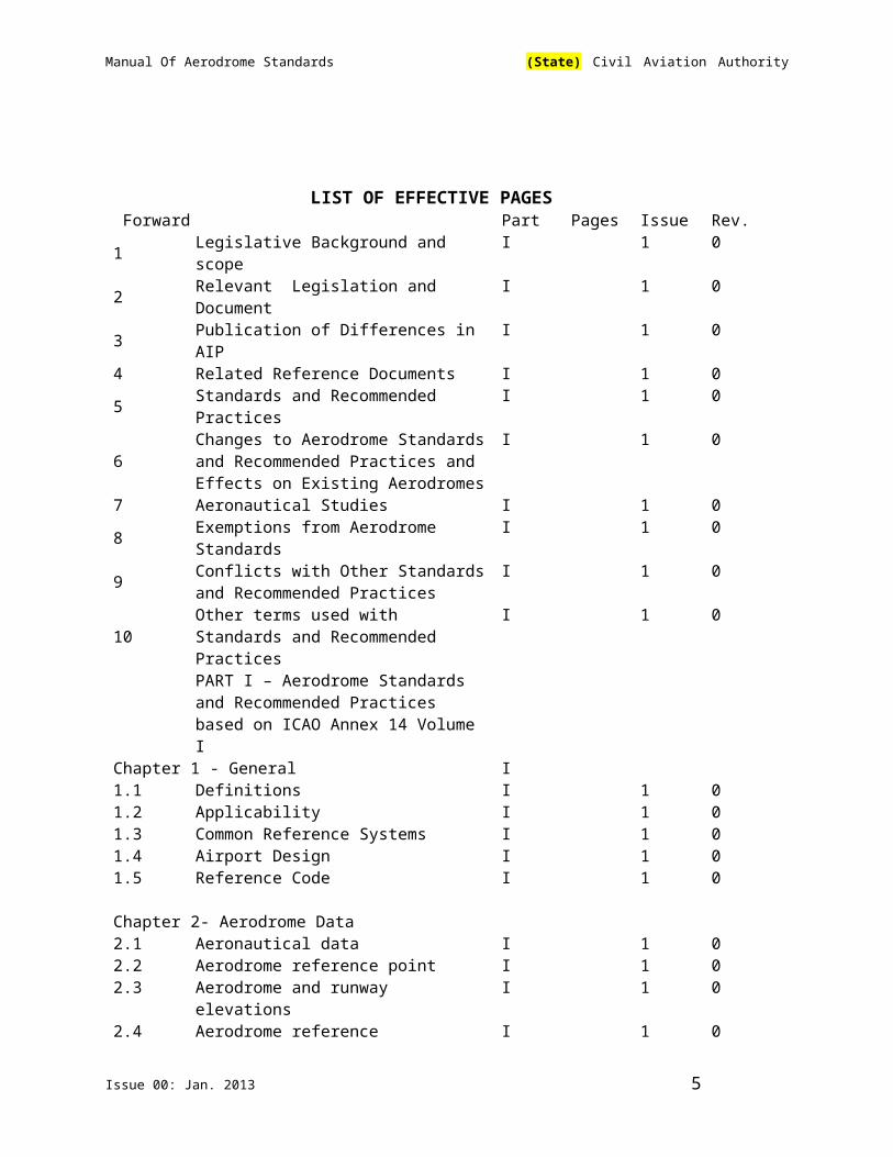
LIST OF EFFECTIVE PAGES Forward Part Pages Issue Rev.1 Legislative Background and scope I 1 02 Relevant Legislation and Document I 1 03 Publication of Differences in AIP I 1 04 Related Reference Documents I 1 0
Issue 00: Jan. 2013 4
Manual Of Aerodrome Standards (State) Civil Aviation Authority
5 Standards and Recommended Practices I 1 0
6Changes to Aerodrome Standards and Recommended Practices and Effects on Existing Aerodromes
I 1 0
7 Aeronautical Studies I 1 08 Exemptions from Aerodrome Standards I 1 0
9 Conflicts with Other Standards and Recommended Practices
I 1 0
10 Other terms used with Standards and Recommended Practices
I 1 0
PART I – Aerodrome Standards and Recommended Practices based on ICAO Annex 14 Volume I
Chapter 1 - General I1.1 Definitions I 1 01.2 Applicability I 1 01.3 Common Reference Systems I 1 01.4 Airport Design I 1 01.5 Reference Code I 1 0
Chapter 2- Aerodrome Data2.1 Aeronautical data I 1 02.2 Aerodrome reference point I 1 02.3 Aerodrome and runway elevations I 1 02.4 Aerodrome reference temperature I 1 02.5 Aerodrome dimension and related
informationI 1 0
2.6 Strength of pavements I 1 02.7 Pré-flight altimeter check locations I 12.8 Declared distances I 1 02.9 Conditions of the movement area and
related facilitiesI 1 0
2.10 Disabled aircraft removal I 1 02.11 Rescue and fire fighting I 1 02.12 Visual approach slope indicator systems I 1 02.13 Coordination between the aerodrome
operator and the aeronautical information services
I 1 0
Chapter 3- Physical characteristic3.1 Runway I 1 03.2 Runway shoulders I 1 03.3 Runway turn pad I 1 03.4 Runway strip I 1 03.5 Runway end safety area I 1 03.6 Clearway I 1 03.7 Stopways I 1 03.8 Radio altimeter operating area I 1 03.9 Taxiway I 1 03.10 Taxiway shoulders I 1 0
Issue 00: Jan. 2013 5

Manual Of Aerodrome Standards (State) Civil Aviation Authority
3.11 Taxiway strip I 1 03.12 Runway-holding positions, intermediate
holding positions and road-holding positions
I 1 0
3.13 Apron I 1 03.14 Isolated aircraft parking position I 1 0
Chapter 4- Obstacle restriction and removal
4.1 Obstacle limitation surfaces I 1 04.2 Obstacle limitation requirements I 1 0
4.3 Objects outside the obstacle limitation surfaces
I 1 0
4.4 Other objects I 1 04.5 Sheilding principle I 1 0
Chapter 5- Visual aids for navigation 5.1 Indicators and signalling devices I 1 05.2 Markings I 1 05.3 Lights I 1 05.4 Signs I 1 05.5 Markers I 1 0
Chapter 6 – Visual aids for denoting obstacle6.1 Objects to be marked and/or lighted I 1 06.2 Marking of objects I 1 06.3 Lighting of objects I 1 0
Chapter 7 – Visual aids for denoting restricted use areas
7.1 Closed runways and taxiways, or parts thereof
I 1 0
7.2 Non-load-bearing surfaces I 1 07.3 Pre-threshold Area I 1 07.4 Unserviceable areas I 1 0
Chapter 8 – Electrical Systems8.1 Primary power supply I 1 08.2 System design I 1 08.3 Monitoring I 1 0
Chapter 9 – Aerodrome operational services, equipment and installations 9.1 Aerodrome emergency planning I 1 09.2 Rescue and fire fighting I 1 09.3 Disabled aircraft removal I 1 09.4 Wildlife strike hazard reduction I 1 09.5 Apron management services I 1 09.6 Ground servicing of aircraft I 1 09.7 Aerodrome vehicle operations I 1 0
Issue 00: Jan. 2013 6

Manual Of Aerodrome Standards (State) Civil Aviation Authority
9.8 Surface movement guidance and control systems
I 1 0
9.9 Siting and construction of equipment and installations on operational areas
I 1 0
9.10 Fencing I 1 09.11 Security Lighting I 1 0
1Chapter 10 – Aerodrome maintenance10.1 General I 1 010.2 Pavements I 1 010.3 Runway pavement overlays I 1 010.4 Visual aids I 1 0
Part II–Aerodrome works safety, safety management system and accident/incident reporting and investigation procedures
Chapter I – Aerodrome works safety1.1 Introduction II 1 01.2 Aerodrome works plan II 1 0
1.3 Management and control of aerodrome works
II 1 0
1.4 Markers, Markings and Lights II 1 01.5 Communication Equipment II 1 01.6 Works near aircraft movement areas II 1 01.7 Completion II 1 01.8 Content of works safety plan II 1 0
Chapter 2 – Safety management
2.2 Scope and applicability II 1 02.3 General II 1 02.4 Safety policies and objectives II 1 0
2.5 Organisational structure and responsibilities
II 1 0
2.6 SMS implementation II 1 0
2.7 Coordination of emergency response planning
II 1 0
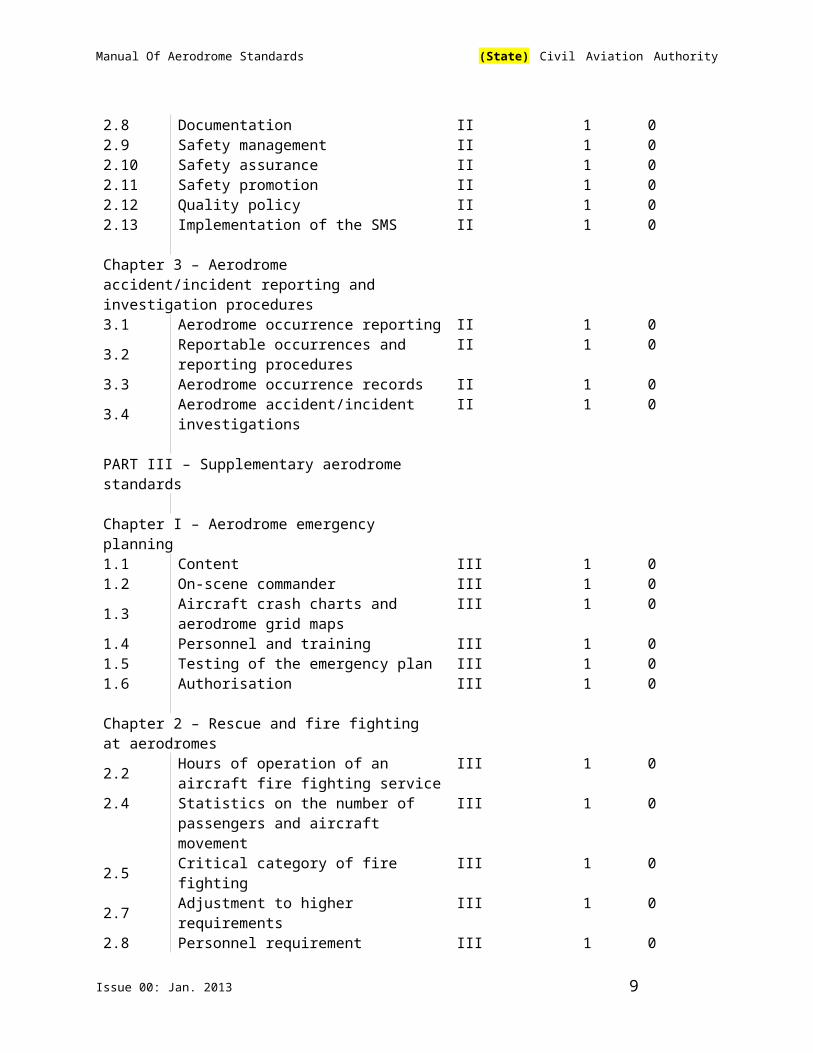
2.8 Documentation II 1 02.9 Safety management II 1 02.10 Safety assurance II 1 02.11 Safety promotion II 1 02.12 Quality policy II 1 02.13 Implementation of the SMS II 1 0
Chapter 3 – Aerodrome accident/incident reporting and investigation procedures3.1 Aerodrome occurrence reporting II 1 0
3.2 Reportable occurrences and reporting procedures
II 1 0
Issue 00: Jan. 2013 7

Manual Of Aerodrome Standards (State) Civil Aviation Authority
3.3 Aerodrome occurrence records II 1 0
3.4 Aerodrome accident/incident investigations
II 1 0
PART III – Supplementary aerodrome standards
Chapter I – Aerodrome emergency planning1.1 Content III 1 01.2 On-scene commander III 1 0
1.3 Aircraft crash charts and aerodrome grid maps
III 1 0
1.4 Personnel and training III 1 01.5 Testing of the emergency plan III 1 01.6 Authorisation III 1 0
Chapter 2 – Rescue and fire fighting at aerodromes
2.2 Hours of operation of an aircraft fire fighting service
III 1 0
2.4 Statistics on the number of passengers and aircraft movement
III 1 0
2.5 Critical category of fire fighting III 1 02.7 Adjustment to higher requirements III 1 02.8 Personnel requirement III 1 02.9 Response readiness III 1 0
Chapter 3 – Aerodrome wildlife planning and management 3.1 Application III 1 03.2 Wildlife strikes III 1 03.3 Risk analysis III 1 03.4 Aerodrome wildlife management plan III 1 03.5 Training III 1 0
Part IV – Heliport
Chapter 1 – Introduction 1.1 Definitions IV 1 01.2 Applicability IV 1 01.3 Common reference systems IV 1 0
Chapter 2 – Heliport data2.1 Aeronautical data IV 1 02.2 Heliport reference point IV 1 02.3 Heliport elevation IV 1 02.4 Heliport distance and related information IV 1 02.5 Declared distances IV 1 0
2.6Coordination between aeronautical information service and heliport authorities
IV 1 0
Issue 00: Jan. 2013 8
Manual Of Aerodrome Standards (State) Civil Aviation Authority
Chapter 3 – Physical characteristics3.1 Surface level heliports IV 1 03.2 Elevated heliports IV 1 03.3 Helidecks IV 1 03.4 Shipboard heliports IV 1 0
Chapter 4 – Obstacle restriction and removal 4.1 Obstacle limitation surfaces and sectors IV 1 04.2 Obstacle limitation requirements IV 1 0
1 0Chapter 5 – Visual aids5.1 Indicators IV 1 05.2 Markings and markers IV 1 05.3 Rescue and fire fighting IV 1 0
Part V – Aerodrome Certification 1.1 Introduction V 1 0
1.2 Phase I-Dealing with expression of interest
V 1 0
1.3 Phase II-Assessing the formal application
V 1 0
1.4 Phase III- Assessing the aerodrome facilities and equipment
V 1 0
1.5 Phase IV-Issuing or refusing an aerodrome certificate
V 1 0
1.6 Phase V- Promulgation in the AIP V 1
App. A1 List of related reference documents App. 1 0
App. A2 Partiulars to be included in aerodrome manual
App. 1 0
Att. A Guidance material App. 1 0
Att. C Framework for the state safety programme(SSP)
Att. 1 0
Issue 00: Jan. 2013 9

Manual Of Aerodrome Standards (State) Civil Aviation Authority
TABLE OF CONTENTS
LIST OF EFFECTIVE PAGES............................................................................................................................................5
TABLE OF CONTENTS......................................................................................................................................... 10
ABBREVIATIONS AND SYMBOLS........................................................................................................................ 15
FORWARD......................................................................................................................................................... 17
1 LEGISLATIVE BACKGROUND AND SCOPE..................................................................................................................172 RELEVANT LEGISLATION AND DOCUMENTS.............................................................................................................173 PUBLICATION OF DIFFERENCES IN AIP...................................................................................................................174 RELATED REFERENCE DOCUMENTS........................................................................................................................185 STANDARDS AND RECOMMENDED PRACTICES..........................................................................................................186 CHANGES TO AERODROME STANDARDS AND RECOMMENDED PRACTICES AND EFFECTS ON EXISTING AERODROMES........187 AERONAUTICAL STUDIES.....................................................................................................................................198 EXEMPTIONS FROM AERODROME STANDARDS............................................................................................209 CONFLICT WITH OTHER STANDARDS AND RECOMMENDED PRACTICES.........................................................................2110 OTHER TERMS USED WITH STANDARDS AND RECOMMENDED PRACTICES................................................................21
PART I............................................................................................................................................................... 23
STANDARDS AND RECOMMENDED PRACTICES BASED ON ANNEX 14 VOLUME I.................................................23
CHAPTER 1. GENERAL........................................................................................................................................ 24
1.1 DEFINITIONS................................................................................................................................................241.2 APPLICABILITY..............................................................................................................................................371.3 COMMON REFERENCE SYSTEMS......................................................................................................................371.4 AIRPORT DESIGN..........................................................................................................................................371.5 REFERENCE CODE.........................................................................................................................................38
CHAPTER 2. AERODROME DATA........................................................................................................................ 40
2.1 AERONAUTICAL DATA...................................................................................................................................402.2 AERODROME REFERENCE POINT......................................................................................................................412.3 AERODROME AND RUNWAY ELEVATIONS..........................................................................................................412.4 AERODROME REFERENCE TEMPERATURE...........................................................................................................422.5 AERODROME DIMENSIONS AND RELATED INFORMATION......................................................................................422.6 STRENGTH OF PAVEMENTS.............................................................................................................................432.7 PRE-FLIGHT ALTIMETER CHECK LOCATION.........................................................................................................462.8 DECLARED DISTANCES...................................................................................................................................472.9 CONDITIONS OF THE MOVEMENT AREA AND RELATED FACILITIES..........................................................................472.10 DISABLED AIRCRAFT REMOVAL........................................................................................................................492.11 RESCUE AND FIRE FIGHTING...........................................................................................................................492.12 VISUAL APPROACH SLOPE INDICATOR SYSTEMS..................................................................................................49
Issue 00: Jan. 2013 10

Manual Of Aerodrome Standards (State) Civil Aviation Authority
2.13 COORDINATION BETWEEN THE AERODROME OPERATOR AND AERONAUTICAL INFORMATION SERVICE...........................50
CHAPTER 3. PHYSICAL CHARACTERISTICS.......................................................................................................... 52
3.1 RUNWAYS...................................................................................................................................................523.2. RUNWAY SHOULDERS....................................................................................................................................593.3 RUNWAY TURN PADS....................................................................................................................................603.4 RUNWAY STRIPS...........................................................................................................................................623.5 RUNWAY END SAFETY AREAS.........................................................................................................................653.6 CLEARWAYS.................................................................................................................................................673.7 STOPWAYS..................................................................................................................................................683.8 RADIO ALTIMETER OPERATING AREA...............................................................................................................693.9 TAXIWAYS...................................................................................................................................................703.10 TAXIWAY SHOULDERS....................................................................................................................................763.11 TAXIWAY STRIPS...........................................................................................................................................773.12 HOLDING BAYS, RUNWAY-HOLDING POSITIONS, INTERMEDIATE HOLDING POSITIONS AND ROAD-HOLDING POSITIONS 783.13 APRONS......................................................................................................................................................80
CHAPTER 4. OBSTACLE RESTRICTION AND REMOVAL........................................................................................82
4.1 OBSTACLE LIMITATION SURFACES....................................................................................................................824.2 OBSTACLE LIMITATION REQUIREMENTS.............................................................................................................864.3 OBJECTS OUTSIDE THE OBSTACLE LIMITATION SURFACES......................................................................................934.4 OTHER OBJECTS...........................................................................................................................................934.5. SHIELDING PRINCIPLES...................................................................................................................................94
CHAPTER 5. VISUAL AIDS FOR NAVIGATION....................................................................................................... 96
5.1 INDICATORS AND SIGNALLING DEVICES.............................................................................................................965.2 MARKINGS..................................................................................................................................................985.3 LIGHTS.....................................................................................................................................................1145.4 SIGNS.......................................................................................................................................................1615.5 MARKER...................................................................................................................................................171
CHAPTER 6. VISUAL AIDS FOR DENOTING OBSTACLES......................................................................................175
6.1 OBJECTS TO BE MARKED AND/OR LIGHTED......................................................................................................1756.2 MARKING OF OBJECTS.................................................................................................................................1776.3 LIGHTING OF OBJECTS.................................................................................................................................1796.4 WIND TURBINES.........................................................................................................................................185
CHAPTER 7. VISUAL AIDS FOR DENOTING RESTRICTED USE AREA.....................................................................187
7.1 CLOSED RUNWAYS AND TAXIWAYS, OR PARTS THEREOF....................................................................................1877.2 NON-LOAD-BEARING SURFACES....................................................................................................................1887.3 PRE-THRESHOLD AREA................................................................................................................................1887.4 UNSERVICEABLE AREAS................................................................................................................................189
CHAPTER 8. ELECTRICAL SYSTEMS.................................................................................................................... 191
8.1 PRIMARY POWER SUPPLY.............................................................................................................................1918.2 SYSTEM DESIGN.........................................................................................................................................194
Issue 00: Jan. 2013 11
Manual Of Aerodrome Standards (State) Civil Aviation Authority
8.3 MONITORING............................................................................................................................................194
CHAPTER 9. AERODROME OPERATIONAL SERVICES, EQUIPMENT AND INSTALLATIONS....................................196
9.1 AERODROME EMERGENCY PLANNING.............................................................................................................1969.2 RESCUE AND FIRE FIGHTING.........................................................................................................................1989.3 DISABLED AIRCRAFT REMOVAL......................................................................................................................2069.4 WILDLIFE STRIKE HAZARD REDUCTION...........................................................................................................2069.5 APRON MANAGEMENT SERVICES...................................................................................................................2079.6 GROUND SERVICING OF AIRCRAFT.................................................................................................................2089.7 AERODROME VEHICLE OPERATIONS...............................................................................................................2089.8 SURFACE MOVEMENT GUIDANCE AND CONTROL SYSTEMS.................................................................................2099.9 SITING AND CONSTRUCTION OF EQUIPMENT AND INSTALLATIONS ON OPERATIONAL AREAS...................................2119.10 FENCING...................................................................................................................................................2139.11 SECURITY LIGHTING.....................................................................................................................................213
CHAPTER 10. AERODROME MAINTENANCE.....................................................................................................223
10.1 GENERAL...........................................................................................................................................22310.2. PAVEMENTS..........................................................................................................................................22310.3. RUNWAY PAVEMENT OVERLAYS...................................................................................................................22510.4.0 VISUAL AIDS.........................................................................................................................................226
PART II............................................................................................................................................................ 230
AERODROME WORK SAFETY, SAFETY MANAGEMENT SYSTEM AND ACCIDENT/ INCIDENT REPORTING AND INVESTIGATION PROCEDURES......................................................................................................................... 230
CHAPTER 1. AERODROME WORK SAFETY........................................................................................................ 231
1.1 INTRODUCTION..........................................................................................................................................2311.2 AERODROME WORK PLANS..........................................................................................................................2311.3 MANAGEMENT AND CONTROL OF AERODROME WORKS....................................................................................2331.4 MARKERS, MARKINGS AND LIGHTS...............................................................................................................2341.5 COMMUNICATION EQUIPMENT.....................................................................................................................2341.6 WORKS NEAR AIRCRAFT MOVEMENT AREAS....................................................................................................2351.7 COMPLETION.............................................................................................................................................2351.8 CONTENT OF WORK SAFETY PLAN.................................................................................................................236
CHAPTER 2 – SAFETY MANAGEMENT............................................................................................................... 238
2.2 SAFETY MANAGEMENT SYSTEM-SCOPE AND APPLICABILITY..................................................................................2382.3 GENERAL..................................................................................................................................................2392.4 SAFETY POLICY AND OBJECTIVES....................................................................................................................2392.5 ORGANISATIONAL STRUCTURE AND RESPONSIBILITIES.........................................................................................2402.6 SMS IMPLEMENTATION PLAN.......................................................................................................................2412.7 COORDINATION OF EMERGENCY RESPONSE PLANNING.......................................................................................2422.8 DOCUMENTATION.......................................................................................................................................2422.9 SAFETY RISK MANAGEMENT..........................................................................................................................2422.10 SAFETY ASSURANCE.....................................................................................................................................2432.11 SAFETY PROMOTION....................................................................................................................................245
Issue 00: Jan. 2013 12
Manual Of Aerodrome Standards (State) Civil Aviation Authority
2.12 QUALITY POLICY.........................................................................................................................................2462.13 IMPLEMENTATION OF THE SMS....................................................................................................................246
CHAPTER 3 AERODROME ACCIDENT/INCIDENT REPORTING AND INVESTIGATION PROCEDURES....................248
II.3.1 AERODROME OCCURRENCE REPORTING......................................................................................................248II.3.2 REPORTABLE OCCURRENCES AND REPORTING PROCEDURES............................................................................248II.3.3 AERODROME OCCURRENCE RECORDS.........................................................................................................249II.3.4 AERODROME ACCIDENT/INCIDENT INVESTIGATIONS......................................................................................250
PART III........................................................................................................................................................... 251
SUPPLEMENTARY STANDARDS ON AERODROME EMERGENCY PLANNING, RESCUE AND FIRE FIGHTING, WILDLIFE HAZARD PLANNING AND MANAGEMENT........................................................................................................ 251
CHAPTER 1. AERODROME EMERGENCY PLANNING..........................................................................................252
1.1 CONTENT..............................................................................................................................................2521.2 ON-SCENE COMMANDER.........................................................................................................................2561.3 AIRCRAFT CRASH CHARTS AND AERODROME GRID MAPS..............................................................................2561.4 PERSONNEL AND TRAINING......................................................................................................................2571.5 TESTING OF THE EMERGENCY PLAN.............................................................................................................2581.6 AUTHORISATION...................................................................................................................................259
CHAPTER 2 RESCUE AND FIRE FIGHTING AT AERODROMES.............................................................................260
2.2 HOURS OF OPERATION OF AN AIRCRAFT FIRE-FIGHTING SERVICE..................................................................2602.4 STATISTICS ON THE NUMBER OF PASSENGERS AND AIRCRAFT MOVEMENTS..................................................2602.5 CRITICAL CATEGORY FOR FIRE FIGHTING....................................................................................................2612.7 ADJUSTMENT TO HIGHER REQUIREMENTS................................................................................................2612.8 PERSONNEL REQUIREMENTS.....................................................................................................................2612.9 RESPONSE READINESS..........................................................................................................................275
CHAPTER 3. AERODROME WILDLIFE PLANNING AND MANAGEMENT...............................................................277
3.1 APPLICATION.........................................................................................................................................2773.2 WILDLIFE STRIKES..................................................................................................................................2773.3. RISK ANALYSIS...................................................................................................................................2783.4 AERODROME WILDLIFE MANAGEMENT PLAN............................................................................................2793.5 TRAINING..............................................................................................................................................281
PART IV HELIPORT......................................................................................................................................... 283
CHAPTER 1. INTRODUCTION............................................................................................................................ 284
1.1 DEFINITIONS..............................................................................................................................................2841.2 APPLICABILITY............................................................................................................................................2871.3 COMMON REFERENCE SYSTEMS.....................................................................................................................288
CHAPTER 2. HELIPORT DATA..................................................................................................................... 290
2.1 AERONAUTICAL DATA..............................................................................................................................2902.2 HELIPORT REFERENCE POINT.......................................................................................................................2912.3 HELIPORT ELEVATION..................................................................................................................................291
Issue 00: Jan. 2013 13

Manual Of Aerodrome Standards (State) Civil Aviation Authority
2.4 HELIPORT DIMENSIONS AND RELATED INFORMATION........................................................................................2922.5 DECLARED DISTANCES..................................................................................................................................2932.6 CO-ORDINATION BETWEEN AERONAUTICAL INFORMATION SERVICES AND HELIPORT AUTHORITIES..............................293
CHAPTER 3. PHYSICAL CHARACTERISTICS...................................................................................................... 295
3.1 SURFACE-LEVEL HELIPORTS..........................................................................................................................2953.2 ELEVATED HELIPORTS..................................................................................................................................3023.3 HELIDECKS................................................................................................................................................3073.4 SHIPBOARD HELIPORTS...............................................................................................................................308
CHAPTER 4. OBSTACLE RESTRICTION AND REMOVAL......................................................................................310
4.1 OBSTACLE LIMITATION SURFACES AND SECTORS...............................................................................................3104.2 OBSTACLE LIMITATION REQUIREMENTS...........................................................................................................314
CHAPTER 5. VISUAL AIDS................................................................................................................................ 323
5.1 INDICATORS...............................................................................................................................................3235.2 MARKINGS AND MARKERS...........................................................................................................................3246.1 RESCUE AND FIRE FIGHTING.........................................................................................................................344
PART V........................................................................................................................................................... 347
AERODROME CERTIFICATION.......................................................................................................................... 347
THE PROCESS.................................................................................................................................................. 348
1.2 PHASE 1-DEALING WITH EXPRESSION OF INTEREST...........................................................................................3481.3 PHASE II-ASSESSING THE FORMAL APPLICATION...............................................................................................3491.4 PHASE IV-ASSESSING THE AERODROME FACILITIES AND EQUIPMENT....................................................................3491.5 PHASE V- ISSUING OR REFUSING AN AERODROME CERTIFICATE...........................................................................3501.6 PHASE V- PROMULGATION IN THE AIP...........................................................................................................350
APPENDIX A1 – LIST OF RELATED REFERENCE DOCUMENTS.............................................................................358
APPENDIX A2 – PARTICULARS TO BE INCLUDED IN AN AERODROME MANUAL................................................359
ATTACHMENT A. GUIDANCE MATERIAL........................................................................................................... 371
ATTACHMENT C. FRAMEWORK FOR THE STATE SAFETY PROGRAMME (SSP)..........................................................399
Issue 00: Jan. 2013 14

Manual Of Aerodrome Standards (State) Civil Aviation Authority
ABBREVIATIONS AND SYMBOLS(used in Manual of Aerodrome Standards)
Abbreviations
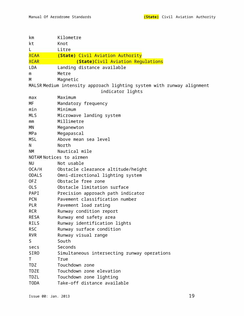
AAE Above aerodrome elevationAAS Airport Advisory ServiceACN Aircraft classification numberAIS Aeronautical Information ServicesALR Aircraft loading ratingAPAPI Abbreviated precision approach path indicatoraprx ApproximatelyARP Aerodrome reference pointASDA Accelerate stop distance availableATF Aerodrome traffic frequencyATS Air traffic servicesC Degrees CelsiusCAT I Category ICAT II Category IICAT III Category IIIcd Candelacm CentimetreDME Distance measuring equipmentE EastEWH Eye to wheel heightFOD Foreign object damageft FootGNSS Global Navigation Satellite SystemGPS Global Positioning SystemGS Glide slopeHAA Height above aerodromeHIAL High intensity approach lightingICAO International Civil Aviation OrganizationIFR Instrument flight rulesILS Instrument landing systemIMC Instrument meteorological conditionsJBI James Brake Index (??)K Degree Kelvinkg Kilogramkm/h Kilometre per hourkm Kilometrekt KnotL LitreXCAA (State) Civil Aviation AuthorityXCAR (State)Civil Aviation RegulationsLDA Landing distance availablem MetreM Magnetic
Issue 00: Jan. 2013 15

Manual Of Aerodrome Standards (State) Civil Aviation Authority
MALSR Medium intensity approach lighting system with runway alignment indicator lights
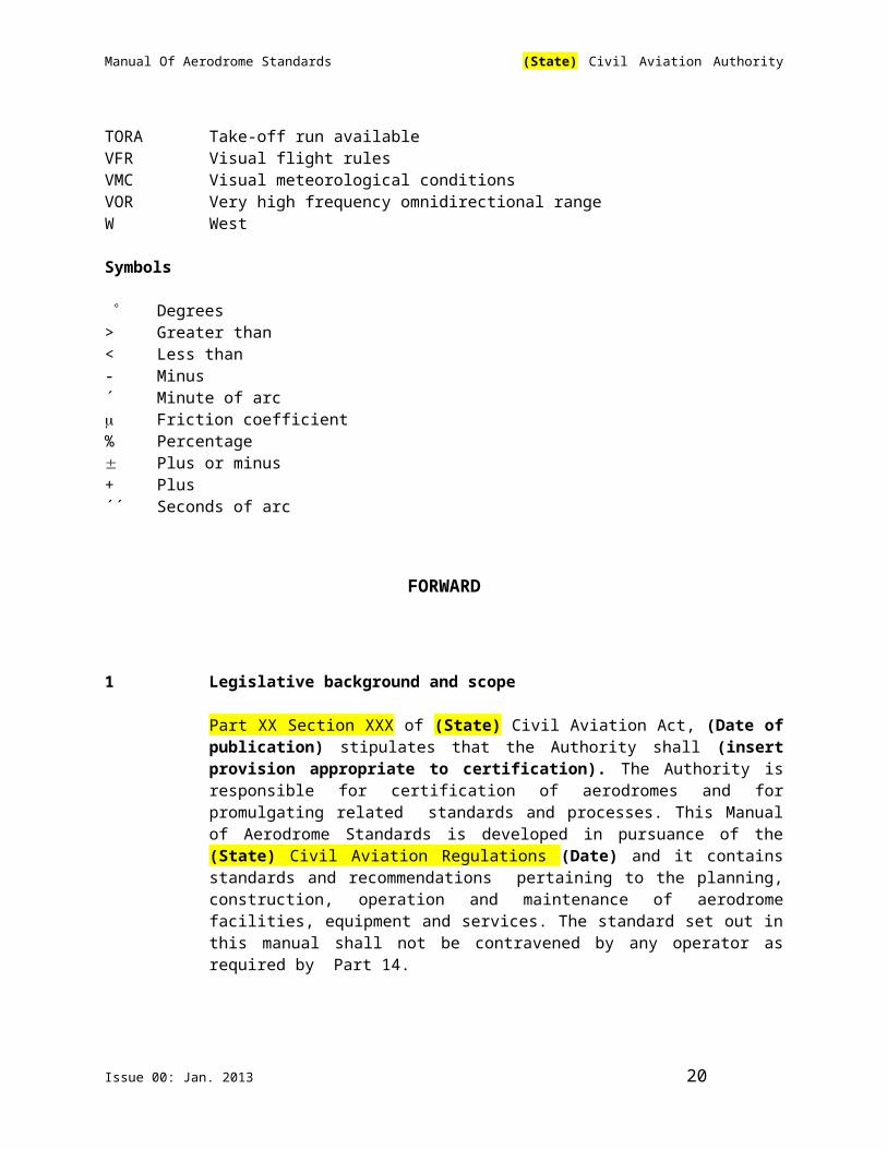
max MaximumMF Mandatory frequencymin MinimumMLS Microwave landing systemmm MillimetreMN MeganewtonMPa MegapascalMSL Above mean sea levelN NorthNM Nautical mileNOTAM Notices to airmenNU Not usableOCA/H Obstacle clearance altitude/heightODALS Omni-directional lighting systemOFZ Obstacle free zoneOLS Obstacle limitation surfacePAPI Precision approach path indicatorPCN Pavement classification numberPLR Pavement load ratingRCR Runway condition reportRESA Runway end safety areaRILS Runway identification lightsRSC Runway surface conditionRVR Runway visual rangeS Southsecs SecondsSIRO Simultaneous intersecting runway operationsT TrueTDZ Touchdown zoneTDZE Touchdown zone elevationTDZL Touchdown zone lightingTODA Take-off distance availableTORA Take-off run availableVFR Visual flight rulesVMC Visual meteorological conditionsVOR Very high frequency omnidirectional rangeW West
Symbols
Degrees> Greater than< Less than- Minus´ Minute of arc Friction coefficient% Percentage Plus or minus
Issue 00: Jan. 2013 16
Manual Of Aerodrome Standards (State) Civil Aviation Authority
+ Plus´´ Seconds of arc
FORWARD
1 Legislative background and scope
Part XX Section XXX of (State) Civil Aviation Act, (Date of publication) stipulates that the Authority shall (insert provision appropriate to certification). The Authority is responsible for certification of aerodromes and for promulgating related standards and processes. This Manual of Aerodrome Standards is developed in pursuance of the (State) Civil Aviation Regulations (Date) and it contains standards and recommendations pertaining to the planning, construction, operation and maintenance of aerodrome facilities, equipment and services. The standard set out in this manual shall not be contravened by any operator as required by Part 14.
The scope of this manual is confined to the safety, regularity and efficiency aspects of aerodrome facilities, equipment and operations. It does not cover such aspects as those related to aeronautical meteorology, the administration of aerodrome finances and the servicing of passengers and cargo. It also excludes air traffic services and aeronautical information services, although their coordination with the aerodrome operator, which forms an integral part of an aerodrome’s operations, has been incorporated.
2 Relevant legislation and documents
The relevant legislation and document hierarchy relating to the certification and safe operation of aerodromes consists of:
(a) the (State) Civil Aviation Act (Date) as may be amended from time to time;
(b) (State) Civil Aviation Regulations (XCAR) Part 14 (c) this Manual of Aerodrome Standards (with references to relevant
sections of ICAO Annex 14 and related guidance material); and
(d) Any applicable Directives, Instructions, Circulars and/or Publications, as and when published, by the Authority
3 Publication of differences in AIP
Differences between the Standards prescribed in this Manual and those contained in ICAO Annex 14, Vol. I&II, if any, are promulgated through Aeronautical Information Publications (AIP) and also notified to ICAO
Issue 00: Jan. 2013 17

Manual Of Aerodrome Standards (State) Civil Aviation Authority
Aerodrome operators shall publish any differences between the provisions at their aerodromes and the Standards prescribed in this Manual under the Aerodrome (ARD) section of the AIP.
4 Related reference documents
This Manual should as specified be read in conjunction with other guidance documents published by the Authority and ICAO.
5 Standards and recommended practices
Standards and Recommended Practices in the context of this Manual of Aerodrome Standards are defined as follows:
Standards: Any specification for physical characteristics, configuration, material, performance, personnel or procedure, the uniform application of which is
recognised as necessary for the safety or regularity of international air navigation and to which aerodrome operators shall conform in accordance with the provisions of the XCAR Part 14 and this Manual .
Recommended Practices: Any specification for physical characteristics, configuration, material, performance, personnel or procedure, the uniform application of which is recognised as desirable in the interest of safety, regularity or efficiency of international air navigation and to which aerodrome operators should endeavour to conform in accordance with the provisions of the XCAR Part 14 and this Manual.
In this Manual of Standards, standards are identified by the words ‘must’ or ‘shall’. Unless otherwise exempted pursuant to XCAR, Part 14 by the Director General of (State) Civil Aviation Authority, they shall be complied with at all times. Figures, appendices and tables associated with these standards form part of the main document and have the same status as the primary text. This Manual of Standards may also require standards from other documents to be followed. In such cases, the referred standards become part of this Manual.
Recommended practices are identified by the words ‘should’ or ‘may’. Figures, appendices and tables associated with these recommended practices form part of the main document and have the same status as the primary text.
6 Changes to Aerodrome Standards and Recommended Practices and Effects on Existing Aerodromes.
Standards and recommended practices are subject to change from time to time. In general, existing aerodrome facilities may not need to be immediately modified in accordance with new standards and/or recommended practices that arise, unless advance notice has been given for the aerodrome operator to comply. The (State) Civil Aviation Authority will determine and promulgate an appropriate
Issue 00: Jan. 2013 18
Manual Of Aerodrome Standards (State) Civil Aviation Authority
time frame, depending on the critical nature of the requirement and other aerodrome operational considerations, for such revisions in standards and recommended practices to be applicable, so that they can be complied with by the aerodrome operators concerned.
Pursuant to the above, in the interim and unless otherwise directed by the Authority, an aerodrome operator’s existing facility that does not meet the new standards specified in this Manual must continue to comply with the standards that were applicable to it under the conditions of the issuance of its Aerodrome Certificate.
At a certified aerodrome, an existing aerodrome facility that does not comply with this Manual must be identified and recorded in the Aerodrome Manual described. It must include the date or period when that facility was first introduced or last upgraded and an indication from the aerodrome operator of a plan or timescale to bring the facility in compliance with this Manual. As part of the site safety audits conducted by the (State) Civil Aviation Authority, evidence to demonstrate efforts to implement the above mentioned plan or timescale may be required.
Other than existing aerodrome facilities and equipment that are allowed to continue to be in use, or exemptions granted to the aerodrome operator for specific cases of consideration, an aerodrome operator is expected to comply with the standards contained in this Manual when introducing a new aerodrome facility or equipment, or when carrying out replacement or improvement works on an existing facility or equipment, unless the replacement or improvement works is limited to those of very minor nature.
7 Aeronautical Studies
Where an aerodrome operator is not able to comply with any standard or recommended practice stipulated in this Manual, an aeronautical study may be conducted to assess the impact of deviations from the standards. The purpose of such studies is to present alternative means of ensuring the safety of aircraft operations, to estimate the effectiveness of each alternative and to recommend procedures to compensate for the deviation.
An aeronautical study is most frequently undertaken during the planning of a new airport or new airport facility, or during the certification of an existing aerodrome. It may also be carried out when aerodrome standards cannot be met as a result of development.
An aeronautical study is a study of an aeronautical problem carried out by an aerodrome operator to identify possible solutions and select a solution that is acceptable without degrading safety. The (State) Civil Aviation Authority will review these studies on a case by case basis and determine their acceptability.
Technical analysis will provide justification for a deviation on the grounds that an equivalent level of safety can be attained by other means. It is generally applicable on situations where the cost of correcting a problem that violates a
Issue 00: Jan. 2013 19
Manual Of Aerodrome Standards (State) Civil Aviation Authority
standard is excessive but where the unsafe effects of the problem can be overcome by some procedural or other means which offer both practical and reasonable solutions.
In conducting a technical analysis, an aerodrome operator should draw upon their practical experience and specialised knowledge. The aerodrome operator may also consult other specialists in relevant areas. When considering alternative procedures in the deviation approval process, it is essential to bear in mind the safety objective of the aerodrome certification regulations and the applicable standards and recommended practices so that the intent of the regulations is not circumvented.
In some instances, the only reasonable means of providing an equivalent level of safety is to adopt suitable procedures and to require, as a condition of certification, that cautionary advice be published in the appropriate AIS publications.
The determination to require caution will be primarily dependent on two considerations:
(i) a pilot’s need to be made aware of potentially hazardous conditions; and
(ii) the responsibility of the aerodrome operator to publish deviations from standards and recommended practices that would otherwise be assumed under the certificate status.
8 Exemptions from Aerodrome Standards
When an aerodrome is not able to comply with any standard specified in this Manual, the aerodrome operator may apply for exemptions from the relevant standard. Applications must be supported, in writing, by cogent reasons including any aeronautical study conducted and their associated results, and where appropriate, an indication of when compliance with the current standards can be expected.
Under the Aerodrome Regulations, the DG-XCAA may, after taking into account all safety-related aspects and operating circumstances, exempt, by notice in writing, any aerodrome operator including compliance with any standard prescribed in this Manual.
Any exemption granted by the Authority shall be subject to any condition or procedure specified by the DG, XCAA in the relevant Aerodrome Certificate as being necessary in the interest of safety.
When an aerodrome does not comply with any standard specified in this Manual, the DG, XCAA may determine after taking into consideration such aeronautical or other studies as he deems fit, any condition or procedure necessary to ensure that the aerodrome attains a level of safety equivalent to that established by the standard. The aerodrome operator shall ensure that his
Issue 00: Jan. 2013 20
Manual Of Aerodrome Standards (State) Civil Aviation Authority
aerodrome complies with any condition or procedure determined by the DG, XCAA.
Any deviation of an aerodrome from any standard shall be set out in an endorsement to the relevant Aerodrome Certificate.
Exemptions granted to an aerodrome operator must also be recorded in the Aerodrome Manual. The Aerodrome Manual must contain details of the exemption, reason that the exemption was requested for, any resultant limitations, conditions or procedures imposed, and other related safety information.
An exemption granted in respect of an existing facility shall continue to apply until its expiry date.
9 Conflict with Other Standards and Recommended Practices
Compliance with the standards and recommended practices specified in this Manual does not absolve an aerodrome operator from obligations in respect of requirements prescribed by other government or statutory authorities. Where another statutory requirement conflicts with the provisions of this Manual, the matter must be referred to XCAA for resolution.
10 Other Terms used with Standards and Recommended Practices
The status of other terms used jointly with standards and recommended practices in this Manual is explained as follows:
Appendices
Appendices contain materials grouped separately for convenience but forming part of the standards and recommended practices.
Definitions
Definitions do not have independent status but is an essential part of each standard and recommended practice in which the term is used, since a change in the meaning of the term would affect the specifications.
Tables and Figures
Tables and Figures add to or illustrate a standard or recommended practice and which are referred to herein, form part of the associated standard or recommended practice and have the same status.
Introductions
Issue 00: Jan. 2013 21
Manual Of Aerodrome Standards (State) Civil Aviation Authority
Introductions comprise explanatory material introduced at the beginning of parts, chapters, or sections of this Manual to assist in the understanding of the application of the text.
Notes
Notes are included in the text, where appropriate, to give factual information or references bearing on the standards and recommended practices in question, but do not constitute part of the standards or recommended practices.
Attachments
Attachments comprise material supplementary to the standards and recommended practices, or are included as a guide to their application.
Issue 00: Jan. 2013 22

Manual Of Aerodrome Standards (State) Civil Aviation Authority
PART ISTANDARDS AND RECOMMENDED PRACTICES BASED ON ANNEX
14 VOLUME I
Issue 00: Jan. 2013 23
Manual Of Aerodrome Standards (State) Civil Aviation Authority
CHAPTER 1. GENERAL
1.1 Definitions
Accident An occurrence associated with the operation of an aircraft which takes place between the time any person boards the aircraft with the intention of flight until such time as all such persons have disembarked, in which
a) a person is fatally or seriously injured as a result of being in the aircraft, or direct contact with any part of the aircraft, including which have become detached from the aircraft, or direct exposure to jet blast, except when the injury are from natural causes, self-inflicted, or inflicted by other persons, or when the injuries are to stowaways hiding outside the areas normally available to the passengers and crew or;
b) the aircraft sustains damage or structural failure which adversely affects the structural strength, performance or flight characteristics of the aircraft, and would normally require major repair or replacement of the affected component except for engine failure or damage, whether damage is limited to the engine, its cowlings or accessories; or for damage limited to propellers, wing tips, antennas, tyres, brakes, fairings, small dents or puncture holes in the aircraft skin; or
c) the aircraft is missing or is completely inaccessible.
Accuracy. A degree of conformance between the estimated o measured value and the true value.
Note—For measured positional data the accuracy is normally expressed in terms of a distance from a stated position within which there is a defined confidence of the true position falling
Aerodrome. A defined area on land or water (including any buildings,installation and equipment) intended to be used, either wholly or in part, for the arrival, departure and surface movement of aircraft
Issue 00: Jan. 2013 24
Manual Of Aerodrome Standards (State) Civil Aviation Authority
Aerodrome beacon. Aeronautical beacon used to indicate the location of an aerodrome from the air.
Aerodrome Certificate. The certificate issued by the (State) Civil Aviation Authority under XCAR Part 14 for the operation of an aerodrome.
Aerodrome elevation. The elevation of the highest point of the landing area.
Aerodrome facilities and equipment
Facilities and equipment, inside or outside the boundaries of and aerodrome,that are constructed or installed and maintained for the arrival, departure and surface movement of aircraft.
Aerodrome identification sign.
A sign placed on an aerodrome to aid in identifying the aerodrome from the air.
Aerodrome incident. An incident involving an aircraft operation and
a) an obstruction either on the aerodrome operational area or protruding into the aerodrome obstacle limitation .surfaces; or
b) a defective visual aid; or
c) a defective surface of a manoeuvring area; or
d) any other hazardous or potentially hazardous situation
Aerodrome manual. The manual forming part of the application for an Aerodrome Certificate under the XCAR, Part 14 including any amendments thereto made in accordance accepted/approved by the DG
Aerodrome operator. In relation to a certified aerodrome, means the holder of an Aerodrome Certificate.
Aerodrome reference. The designated geographical location of an aerodrome. point
Manual of Aerodrome Standards.
A document containing the Aerodrome Standards and Recommended Practices and guidance Materials consistent with the provisions of ICAO Annex 14 Volumes I&II pertaining to the planning, operation and maintenance of aerodrome services, facilities and equipment, to be complied with by the aerodrome operators.
Aerodrome traffic a) Light: Where the number of movements in the mean
Issue 00: Jan. 2013 25

Manual Of Aerodrome Standards (State) Civil Aviation Authority
Density busy hour is not greater than 15 per runway or typically less than 20 total aerodrome movements.
b) Medium: Where the number of movements in the mean busy hour is of the order of 16 to 25 per runway or typically between 20 to 35 total aerodrome movements.
c) Heavy: Where the number of movements in the mean busy hour is of the order of 26 or more per runway or typically more than 35 total aerodrome movements.
Note 1 — The number of movements in the mean busy hour is the arithmetic mean over the year of the number of movements in the daily busiest hour
Note 2 — Either a take-off or landing constitutes a movement.
Aeronautical beacon. An aeronautical ground light visible at all azimuths, either continuously or intermittently, to designate a particular point on the surface of the earth.
Aeronautical ground light.
Any light specially provided as an aid to air navigation, other than a light displayed on an aircraft.
Aeronautical information circular.
A notice containing information which relates to flight safety air navigation, technical, administrative or legislative matters.
Aeronautical information publication.
A publication issued by and with the authority of the Aeronautical Information Services and containing aeronautical information of a lasting character essential to air navigation.
Aeronautical information service.
The services established within the defined area of coverage responsible for the provision of aeronautical information and data necessary for the safety, regularity and efficiency of air navigation and, where appropriate, includes the personnel and facilities employed to provide information pertaining to the availability of air navigation services and their associated procedures necessary for the safety, regularity and efficiency of air navigation.
Aeroplane reference field length
The minimum field length required for take-off at maximum certificated take-off mass, sea-level, standard atmospheric conditions, still air and zero runway slope, as shown in the appropriate aeroplane flight manual prescribed by the certificating authority or equivalent data from the aeroplane manufacturer. Field length means balanced field length for aeroplanes, if applicable, or take-off distance in other cases
Issue 00: Jan. 2013 26
Manual Of Aerodrome Standards (State) Civil Aviation Authority
Note–Attachment A, Section 2 provides information on the concept of balanced field length and the ICAO Airworthiness Manual (Doc 9760) contains detailed guidance on matters related to take-off distance.
Aircraft Classification Number (ACN).
A number expressing the relative effect of an aircraft on a pavement for a specified standard sub grade category.
Note.—The aircraft classification number is calculated with respect to the centre of gravity (CG) position which yields the critical loading on the critical gear. Normally the aft most CG position appropriate to the maximum. gross apron(ramp) mass is used to calculate the ACN. In exceptional cases the forward most CG position may result in the nose gear loading being more critical.
Aircraft stand. A designated area on an apron intended to be used for parking an aircraft.
Apron. A defined area, on a land aerodrome, intended to accommodate aircraft for purposes of loading or unloading passengers, mail or cargo, fuelling, parking or maintenance.
Apron management. A service provided to regulate the activities and the movement service of aircraft and vehicles on an apron.
Authority. The civil aviation authority responsible for the oversight of civil aviation in (State) ((State) Civil Aviation Authority)
Balked landing. A landing manoeuvre that is unexpectedly discontinued at any point below the obstacle clearance altitude/height (OCA/H).
Barrette. Three or more aeronautical ground lights closely spaced in a transverse line so that from a distance they appear as a short bar of light.
Bird incident. An incident wherea) there is a collision between an aircraft and one or
more birds; b) where one or more birds pass sufficiently close to
an aircraft in flight to cause alarm to the pilot.
Calendar. Discrete temporal reference system that provides the basis for defining temporal position to a resolution of one day (ISO 19108*)
Capacitor discharge A lamp in which high-intensity flashes of extremely short
Issue 00: Jan. 2013 27

Manual Of Aerodrome Standards (State) Civil Aviation Authority
light. Light duration are produced by the discharge of electricity at high voltage through a gas enclosed in a tube.
Certified aerodrome. An aerodrome whose operator has been granted an Aerodrome Certificate.
Clearway. A defined rectangular area on the ground or water under the control of the aerodrome operator, selected or prepared as a suitable area over which an aeroplane may make a portion of its initial climb to a specified height.
Controlled aerodrome. An aerodrome provided with air traffic control services
Cyclic redundancy check (CRC).
A mathematical algorithm applied to the digital expression of data that provides a level of assurance against loss or alteration of data.
Data quality. A degree or level of confidence that the data provided meet the requirements of the data user in terms of accuracy, resolution and integrity.
Datum. Any quantity or set of quantities that may serve as reference or basis for the calculation of other quantities (ISO 19104**).
Declared distances a) Take-off run available (TORA). The length of runway declared available and suitable for the ground run of an aeroplane taking off.
b) Take-off distance available (TODA). The length of the take-off run available plus the length of the
clearway, if provided.
c) Accelerate-stop distance available (ASDA). The length of the take-off run available plus the length of the stop way, if provided.
d) Landing distance available (LDA). The length of runway which is declared available and suitable for the ground run of an aeroplane landing.
Dependent parallel approaches
Simultaneous approaches to parallel or near-parallel instrument runways where radar separation minima between aircraft on adjacent extended runway centre lines are prescribed.
Director-General. The Director-General of the (State) Civil Aviation Civil Aviation Authority, who is also referred to as the Chief Executive Officer of the (State) Civil Aviation Authority
Displaced threshold. A threshold not located at the extremity of a runway.
Effective intensity. The effective intensity of a flashing light is equal to the intensity of a fixed light of the same colour which will produce the same visual range under identical conditions
Issue 00: Jan. 2013 28

Manual Of Aerodrome Standards (State) Civil Aviation Authority
of observation.
Ellipsoid height. The height related to the reference ellipsoid, measured along the (Geodetic height) ellipsoid outer normal through the point in question.
Fatal injury. Any injury which results in death within 30 days of the accident.
Fixed light. A light having constant luminous intensity when observed from a fixed point.
Frangible object. An object of low mass designed to break, distort or yield on impact so as to present the minimum hazard to aircraft.
Note — Guidance on design for frangibility is contained in the Aerodrome Design Manual (DOC 9157), Part 6
Geodetic datum. A minimum set of parameters required to define location and orientation of the local reference system with respect to the global reference system/frame.
Geoid. The equipotential surface in the gravity field of the Earth which coincides with the undisturbed mean sea Level (MSL) extended continuously through the continentsNote — The geoid is irregular in shape because of Local gravitational disturbances (wind tides, salinity, current, etc.) and the direction of gravity is perpendicular to the geoid at every point
Geoid undulation. The distance of the geoid above (positive) or below (negative) the mathematical reference ellipsoid.
Note.—In respect to the World Geodetic System- 1984 (WGS-84) defined ellipsoid, the difference between the WGS-84 ellipsoidal height and orthometric height represents WGS-84 geoid undulation.
Gregorian calendar. Calendar in general use; first introduced in 1582 to define a year that more closely approximates the tropical year than the Julian calendar (ISO 19108***).
Hazard beacon. An aeronautical beacon used to designate a danger to air navigation.
Heliport. An aerodrome or a defined area on a structure intended to be used wholly or in part for the arrival, departure and surface movement of helicopters.
Holding bay. A defined area where aircraft can be held, or bypassed, to facilitate efficient surface movement of aircraft.
Issue 00: Jan. 2013 29
Manual Of Aerodrome Standards (State) Civil Aviation Authority
Human factors principle. Principles which apply to aeronautical design, certification,training, operations and maintenance and which seek safe interface between the human and other system components by proper consideration to human performance.
Human performance Human capabilities and limitations which have an impact on the safety and efficiency of aeronautical operations.
Identification beacon. An aeronautical beacon emitting a coded signal by means of which a particular point of reference can be identified.
Incident. An occurrence, other than an accident, associated with the operation of an aircraft which affects or could affect the safety of operation.
Independent parallel approaches.
Simultaneous approaches to parallel or near-parallel instrument runways where radar separation minima between aircraft on adjacent extended runway centre lines are not prescribed.
Independent parallel departures.
Simultaneous departures from parallel or near parallel instrument Departures runways.
Instrument runway. One of the following types of runways intended for the operation of aircraft using instrument approach procedures:a) Non-precision approach runway. An instrument
runway served by visual aids and a non-visual aid providing at least directional guidance adequate for a straight-in approach.
b) Precision approach runway, category I. An instrument runway served by ILS and/or MLS and visual aids intended for operations with a decision height not lower than 60m (200 ft) and either a visibility not less than 800m or a runway visual range not less than 550m.
c) Precision approach runway, category II. An instrument runway served by ILS and/or MLS and visual aids intended for operations with a decision height lower than 60m (200 ft) but not lower than 30m (100 ft) and a runway visual range not less than 350m.
d) Precision approach runway, category An instrument runway served by ILS and/or MLS to and along the surface of the runway and:A - intended for operations with a decision
height lower than 30m (100ft), or no
Issue 00: Jan. 2013 30
Manual Of Aerodrome Standards (State) Civil Aviation Authority
decision height and a runway visual range not less than 175m.
B - intended for operations with a decision
height lower than 15m (50 ft), or no decision height and a runway visual range less than 175m but not less than 50m.
C - intended for operations with no decision
height and no runway visual range limitations.
Note 1. —See ICAO Annex 10, Volume 1, Part 1, for related ILS and/or MLS specifications
Note 2. —Visual aids need not necessarily be matched to the scale of non-visual aids provided. The criterion for the selection of visual aids is the conditions in which operations are intended to be conducted.
Integrity. A degree of assurance that an aeronautical data and its value has (aeronautical data) not been lost nor altered since the data origination or authorised amendment.
Intermediate holding position.
A designated position intended for traffic control at which taxiing aircraft and vehicles shall stop and hold until further cleared to proceed, when so instructed by the aerodrome control tower.
Investigation. A process conducted for the purpose of accident prevention which includes the gathering and analysis of information, the drawing of conclusions, including the determination of causes and, when appropriate, the making of safety recommendations.
Landing area. That part of a movement area intended for the landing or take-off of aircraft.
Landing direction indicator.
A device to indicate visually the direction currently designatedfor landing and take-off.
Laser-beam free flight zone (LFFZ).
Airspace in the immediate proximity to the aerodrome where the irradiance is restricted to a level unlikely to cause any visual disruption.
Laser-beam critical flight zone (LCFZ).
Airspace in the proximity to the aerodrome but beyond the LFFZ where the irradiance is restricted to a level unlikely to cause glare effects.
Laser-beam sensitive flight zone (LSFZ).
Airspace outside, and not necessarily contiguous with, the LFFZ and LCFZ where the irradiance is restricted to a level
Issue 00: Jan. 2013 31

Manual Of Aerodrome Standards (State) Civil Aviation Authority
unlikely to cause flash-blindness or after-image effectsLighting system reliability.
The probability that the complete installation operates within the specified tolerances and that the system is operationally usable.
Manoeuvring area. That part of an aerodrome to be used for the take-off, landing and taxiing of aircraft, excluding aprons.
Marker. An object displayed above ground level in order to indicate an obstacle or delineate a boundary
Marking. A symbol or group of symbols displayed on the surface of the movement area in order to convey aeronautical information.
Movement area. That part of an aerodrome to be used for the take-off, landing and taxiing of aircraft, consisting of the manoeuvring area and the aprons.
Near-parallel runways. Non-intersecting runways whose extended centre lines have an angle of convergence/divergence of 15 degrees or less.
Non-instrument runway. A runway intended for the operation of aircraft using visual approach procedures.
Normal flight zone (NFZ).
Airspace not defined as LFFZ, LCFZ, or LSFZ, but which must be protected from laser radiation capable of causing biological damage to the eye.
NOTAM or Notice to Airmen.
A notice distributed by means of telecommunication containing information concerning the establishment, condition or change in any aeronautical facility, service or procedure or hazard, the timely knowledge of which is essential to personnel concerned with flight operations
Obstacle. All fixed (whether temporary or permanent) and mobile objects, or parts thereof, that are located on an area intended for the surface movement of aircraft; or extend above a defined surface intended to protect aircraft in flight; or stand outside those defined surfaces and that have been assessed as being a hazard to air navigation.
Obstacle free zone(OFZ).
The airspace above the inner approach surface, inner transitional surfaces, and balked landing surface and that portion of the strip bounded by these surfaces, which is not penetrated by any fixed obstacle other than a low mass and frangibly mounted one required for air navigation purposes.
Obstacle limitation A series of surfaces that define the volume of airspace at
Issue 00: Jan. 2013 32

Manual Of Aerodrome Standards (State) Civil Aviation Authority
Surfaces. and around an aerodrome to be kept free of obstacles in order to permit the intended aircraft operations to be conducted safely and to prevent the aerodrome from becoming unusable by the growth of obstacles around the aerodrome.
Occurrence . An accident or incident.
Orthometric height. Height of a point related to the geoid, generally presented as an MSL elevation.
Pavement classification number(PCN).
A number expressing the bearing strength of a pavement for unrestricted operations.
Precision approach runway.
See ‘Instrument runway’.
Pre-flight information Bulletin.
A presentation of current NOTAM information of operational significance, prepared prior to flight.
Primary runway(s). Runway(s) used in preference to others whenever conditions permit.
Promulgated information incident.
An incident that involves significantly incorrect, inadequate, ormisleading information promulgated in any aeronautical information publication, map or chart.
Protected flight zones. Airspace specifically designated to mitigate the hazardous effects of laser radiation.
Road. An established surface route on the movement area meant for the exclusive use of vehicles.
Road-holding position. A designated position at which vehicles may be required to hold.
Runway. A defined rectangular area on a land aerodrome prepared for the landing and take-off of aircraft.
Runway end safety area (RESA).
An area symmetrical about the extended runway centre line and adjacent to the end of the strip primarily intended to reduce the risk of damage to an aeroplane undershooting or overrunning the runway.
Runway guard lights. A light system intended to caution pilots or vehicle drivers that they are about to enter an active runway.
Runway-holding position.
A designated position intended to protect a runway, an obstacle limitation surface, or an ILS/MLS Critical/sensitive area at which taxiing aircraft and vehicles shall stop and hold, unless otherwise authorised by the aerodrome control
Issue 00: Jan. 2013 33
Manual Of Aerodrome Standards (State) Civil Aviation Authority
tower.Note – In radiotelephony phraseologies, the expression “holding point” is used to designate the runway holding position.
Runway strip. A defined area including the runway and stop way, if provided, that is intended:a) to reduce the risk of damage to aircraft running off a runway; and
b) to protect aircraft flying over the area during take-off or landing operations.
Runway turn pad. A defined area on a land aerodrome adjacent to a runway for the purpose of completing a 180-degree turn on a runway.
Runway visual range (RVR).
The range over which the pilot of an aircraft on the centerline of a runway can see the runway surface markings or the lights delineating the runway or identifying its centre line.
Safety Management System (SMS).
A system for the managing safety including the necessary organisational structure, responsibilities, accountabilities, policies and procedures.
Security incident. An incident that involves unlawful interference.
Segregated parallel operations
Simultaneous operations on parallel or near-parallel instrument runways in which one runway is used exclusively for approaches and the other runway is used exclusively for departures.
Serious incident. An incident involving circumstances indicating that an accident nearly occurred.
Serious injury. Any injury that is sustained by a person in an accident and that
a) requires hospitalisation for more than 48 hours, commencing within seven days from the date the injury was received; or
b) results in a fracture of any bone, except simple fractures of fingers, toes or nose; or
c) involves lacerations which cause severe haemorrhoid nerve, muscle, or tendon damage; or
d) involves any injury to any internal organ; or
Issue 00: Jan. 2013 34

Manual Of Aerodrome Standards (State) Civil Aviation Authority
e) involves second or third degree burns, or any burns affecting more than 5% of the body surface; or
f) involves verified exposure to infectious substances or injurious radiation
Shoulder. An area adjacent to the edge of a pavement so prepared as to provide a transition between the pavement and the adjacent surface.
Sign a) Fixed message sign: A sign presenting only one message.
b) Variable message sign: A sign capable of presenting several pre-determined messages or no message, as applicable.
Signal area An area on an aerodrome used for the display of ground
signals.
State safety Programme. An integrated set of regulations and activities aimed at improving safety.
Station declination. An alignment variation between the zero degree radial of a VOR and true north, determined at the time the VOR station is calibrated.
Stop way. A defined rectangular area on the ground at the end of take-off run available prepared as a suitable area in which an aircraft can be stopped in the case of an abandoned take-off
Switch-over time. The time required for the actual intensity of a light (light) measured in a given direction to fall from 50 per cent and recover to 50 per cent during a power supply change-over, when the light is being operated at intensities of 25 per cent or above.
Take-off runway. A runway intended for take-off only.
Taxiway. A defined path on a land aerodrome established for the taxiing of aircraft and intended to provide a link between one part of the aerodrome and another, including:
a) Aircraft stand taxi lane: A portion of an apron designated as a taxiway and intended to provide access to aircraft stands only.
b) Apron taxiway: A portion of a taxiway system located on an apron and intended to provide a through taxi route across the apron.
Issue 00: Jan. 2013 35

Manual Of Aerodrome Standards (State) Civil Aviation Authority
c) Rapid exit taxiway: A taxiway connected to a runway at an acute angle and designed to allow landing aeroplanes to turn off at higher speeds than are achieved on other exit taxiways thereby minimizing runway occupancy times.
Taxiway intersection. A junction of two or more taxiways.
Taxiway strip. An area including a taxiway intended to protect an aircraft operating on the taxiway and to reduce the risk of damage to an aircraft accidentally running off the taxiway
Threshold. The beginning of that portion of the runway usable for landing.
Touchdown zone The portion of a runway, beyond the threshold, where it is intended landing aeroplanes first contact the runway.
Usability factor. The percentage of time during which the use of a runway or system of runways is not restricted because of the cross-wind component
Note — Cross wind component means the surface wind component at right angles to the runway centre line
Unserviceable area A part of the movement area that is unfit and unavailable for use by aircraft.
Work area. A part of an aerodrome in which maintenance or construction works are in progress.
Note: — Terms and definitions that are shown in singular above shall also take on the same meaning when they are expressed in plural form in this Manual and vice versa.
∗ ISO Standard 19108, Geographic information — Temporal schema∗∗ ISO Standard 19104, Geographic information — Terminology*** ISO Standard 19108, Geographic information — Temporal schema
Issue 00: Jan. 2013 36

Manual Of Aerodrome Standards (State) Civil Aviation Authority
1.2 Applicability
1.2.1 The interpretation of some of the specifications in this manual expressly requires the exercising of discretion, the taking of a decision or the performance of a function by the appropriate authority. In other specifications, the expression appropriate authority does not actually appear although its inclusion is implied. In both cases, the responsibility for whatever determination or action is necessary shall rest with the Authority.
1.2.2 The specifications unless otherwise indicated in a particular context, shall apply to all aerodromes certified in accordance with (State) Civil Aviation Regulations Part 14(2006) and to the extent determined by the Authority to other aerodromes required to be certified in accordance with XCAR Part 14. The specifications of Chapter 3 of this MOS shall apply only to land aerodromes.
1.2.3 Wherever a colour is referred to in this Document, the specifications for that colour given in Appendix 1 shall apply.
1.3 Common Reference Systems
1.3.1 Horizontal reference system - World Geodetic System — 1984 (WGS-84) shall be used as the horizontal (geodetic) reference system. Reported aeronautical geographical coordinates (indicating latitude and longitude) shall be expressed in terms of the WGS-84 geodetic reference datum.
Note. — Comprehensive guidance material concerning WGS-84 is contained in the World Geodetic System — 1984 (WGS-84) Manual (Doc 9674).
1.3.2 Vertical reference system - Mean sea level (MSL) datum, which gives the relationship of gravity-related height (elevation) to a surface known as the geoid, shall be used as the vertical reference system.
Note 1.— The geoid globally most closely approximates MSL. It is defined as the equipotential surface in the gravity field of the Earth which coincides with the undisturbed MSL extended continuously through the continents.
Note 2.— Gravity-related heights (elevations) are also referred to as orthometric heights while distances of points above the ellipsoid are referred to as ellipsoidal heights.
1.3.3 Temporal reference system - The Gregorian calendar and Coordinated Universal Time (UTC) shall be used as the temporal reference system.
1.4 Airport Design
1.4.1 Architectural and infrastructure-related requirements for the optimum implementation of international civil aviation security measures shall be
Issue 00: Jan. 2013 37

Manual Of Aerodrome Standards (State) Civil Aviation Authority
integrated into the design and construction of new facilities and alterations to existing facilities at an aerodrome.
Note.— Guidance on all aspects of the planning of aerodromes including security considerations is contained in the Airport Planning Manual, (Doc 9184) Part 1.
1.4.2 The design of aerodromes shall take into account, where appropriate, land-use and environmental control measures.
Note.— Guidance on land-use planning and environmental control measures is contained in the Airport Planning Manual, (Doc 9184) Part 2.
1.5 Reference Code
Note.— The intent of the reference code is to provide a simple method for interrelating the numerous specifications concerning the characteristics of aerodromes so as to provide a series of aerodrome facilities that are suitable for the aeroplanes that are intended to operate at the aerodrome. The code is not intended to be used for determining runway length or pavement strength requirements. The code is composed of two elements which are related to the aeroplane performance characteristics and dimensions. Element 1 is a number based on the aeroplane reference field length and element 2 is a letter based on the aeroplane wing span and outer main gear wheel span. A particular specification is related to the more appropriate of the two elements of the code or to an appropriate combination of the two code elements. The code letter or number within an element selected for design proposes is related to the critical aeroplane characteristics for which the facility is provided. When applying this Manual, the aeroplanes which the aerodrome is intended to serve are first identified and then the two elements of the code.
1.5.1 An aerodrome reference code (code number and letter) which is selected for aerodrome planning purposes shall be determined in accordance with the characteristics of the aeroplane for which an aerodrome facility is intended.
1.5.2 The aerodrome reference code numbers and letters shall have the meanings assigned to them in Table 1-1.
1.5.3 The code number for element 1 shall be determined from Table 1-1, column 1, selecting the code number corresponding to the highest value of the aeroplane reference field lengths of the aeroplanes for which the runway is intended.
Note.— The determination of the aeroplane reference field length is solely for the selection of a code number and is not intended to influence the actual runway length provided.
Table 1-1. Aerodrome reference code (see 1.13.2-1.13.4)
Code element I Code element 2
Issue 00: Jan. 2013 38

Manual Of Aerodrome Standards (State) Civil Aviation Authority
CodeNumber
1
2
3
4
Aeroplane reference field length
CodeLetter
A
B
C
D
E
F
Wing span Outer main gear wheelspan a
(1) (2) (3)
Less than 800 m
800 m up to but not including 1200 m
1200 m up to but not including 1800 m
1800 m and over
Up to but not including 15 m
15 m up to but notincluding 24 m
24 m up to but notincluding 36 m
36 m up to but notincluding 52 m
52 m up to but notincluding 65 m
65 m up to but notincluding 80 m
up to but not including4.5 m
4.5 m up to but notincluding 6 m
6 m up to but notincluding 9 m
9 m up to but notincluding 14 m
9 m up to but notincluding 14 m
14 m up to but notincluding 16 m
a. Distance between the outside edges of the main gear wheels.
1.5.4 The code letter for element 2 shall be determined from Table 1-1, column 3, by selecting the code letter which corresponds to the greatest wing span, or the greatest outer main gear wing span, whichever gives the more demanding code letter of the aeroplanes for which the facility is intended.
Note.— Guidance to assist the appropriate authority in determining the aerodrome reference code is given in the ICAO Aerodrome Design Manual, Part 1 and 2.
Issue 00: Jan. 2013 39
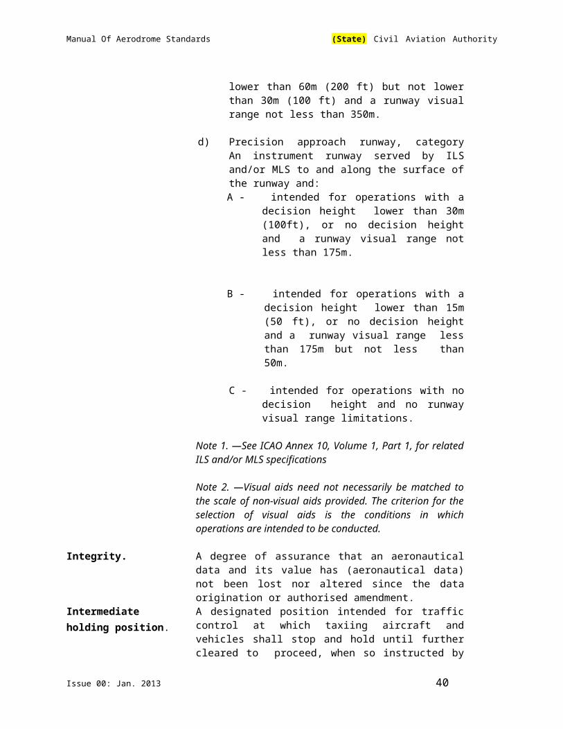
Manual Of Aerodrome Standards (State) Civil Aviation Authority
CHAPTER 2. AERODROME DATA
Note.— This chapter contains specifications relating to the provision of data about aerodromes to be determined and recorded in the Aerodrome Operation Manual and where specified, reported to the regional Aeronautical Information Service.
2.1 Aeronautical Data
2.1.1 Determination and reporting of aerodrome related aeronautical data shall be in accordance with the accuracy and integrity requirements set forth in Table 1 to 5 contained in Appendix E of ICAO Annex 14 Vol. I while taking into account the established quality system procedures. Accuracy requirements for aeronautical data are based upon a 95 per cent confidence level and in that respect, three types of positional data shall be identified:surveyed points (e.g. runway threshold), calculated points (mathematical calculations from known surveyed points of points in space, fixed) and declared points (e.g. flight information region boundary points).
2.1.2 The integrity of aeronautical data shall be maintained throughout the data process from survey/origin to the next intended user. Aeronautical data integrity requirements shall be based upon the potential risk resulting from the corruption of data and upon the use to which the data item is put. Consequently, the following classification and data integrity level shall apply:
(a) critical data, integrity level 1 x 10⁻⁸: there is a high probability when using corrupted critical data that the continued safe flight and landing of an aircraft would be severely at risk with the potential for catastrophe;
(b) essential data, integrity level 1 x 10⁻⁵: there is a low probability when usingcorrupted essential data that the continued safe flight and landing of an aircraft would be severely at risk with the potential for catastrophe;
(c) routine data, integrity level 1 x 10⁻³ : there is a very low probability when using corrupted essential data that the continued safe flight and landing of an aircraft would be severely at risk with the potential for catastrophe.
2.1.3 Protection of electronic aeronautical data while stored or in transit shall be totally monitored by the cyclic redundancy check (CRC). To achieve protection of the integrity level of critical and essential aeronautical data as classified in 2.1.2 above, a 32 or 24 bit CRC algorithm shall apply respectively.
2.1.4 Recommendation — To achieve protection of the integrity level of routine aeronautical data as classified in paragraph 2.1.2 above, a 16 bit CRC algorithm should apply.
Issue 00: Jan. 2013 40

Manual Of Aerodrome Standards (State) Civil Aviation Authority
Note – Guidance material on the aeronautical data integrity quality requirements (accuracy, resolution, integrity, protection and traceability) is contained in the ICAO World Geodetic System – 1984 (WGS-84) Manual (Doc 9674). Supporting material in respect of provisions of Appendix E of ICAO Annex 14 Vol. Irelated to accuracy and integrity of aeronautical data, is contained in RTCA Document DO-201A and European Organization for Civil Aviation Equipment (EUROCAE) Document ED-77, entitled Industry Requirements for Aeronautical Information.
2.1.5 Geographical coordinates including latitude and longitude shall be determined and reported to the Aeronautical Information Services in terms of the World Geodetic System – 1984 (WGS-84) geodetic reference datum, identifying those geographical coordinates which have been transformed into WGS-84 coordinates by mathematical means and whose accuracy of original field work does not meet the requirements in ICAO Annex 14 Vol I, Appendix E Table 1,
2.1.6 The order of accuracy of the field work shall be such that the resulting operational navigational data for the phases of flight will be within the maximum deviations, with respect to an appropriate reference frame, as indicated in the tables contained in ICAO Annex 14 Vol I, Appendix E.
2.1.7 In addition to the elevation (referenced to mean sea level) of the specific surveyed ground positions at aerodromes, geoid undulation (referenced to the WGS-84 ellipsoid) for those positions as indicated in ICAO Annex 14 Vol I, Appendix E shall be determined and reported to the Aeronautical Information Services.
Note 1 – An appropriate reference frame is that which enables WGS-84 to be realized on a given aerodrome and with respect to which all coordinate data are related.
Note 2 – Specifications governing the publication of WGS-84 coordinates are given in ICAO Annex 4, Chapter 2 and ICAO Annex 15, Chapter 3.
2.2 Aerodrome Reference Point
2.2.1 An aerodrome reference point shall be established for an aerodrome.
2.2.2 The aerodrome reference point shall be located near the initial or planned geometric centre of the aerodrome and shall normally remain where first established.
2.2.3 The position of the aerodrome reference point shall be measured and reported to the Aeronautical Information Services in degrees, minutes and seconds.
2.3 Aerodrome and Runway Elevations
2.3.1 The aerodrome elevation and geoid undulation at the aerodrome elevation points shall be measured to the accuracy of one-half metre and reported to the Aeronautical Information Services.
Issue 00: Jan. 2013 41

Manual Of Aerodrome Standards (State) Civil Aviation Authority
2.3.2 For an aerodrome used by International Civil Aviation for non-precision approaches, the elevation and geoid undulation of each threshold, the elevation of the runway end and any significant high and low intermediate points along the runway shall be measured to the accuracy of one-half metre and reported to the Aeronautical Information Services.
2.3.3 For precision approach runway, the elevation and geoid undulation of the threshold, the elevation of the runway end and the highest elevation of the touchdown zone shall be measured to the accuracy of one- quarter metre and reported to the Aeronautical Information Services.
Note – Geoid undulation must be measured in accordance with the appropriate system of coordinates.
2.4 Aerodrome Reference Temperature
2.4.1 An aerodrome reference temperature shall be determined for an aerodrome in degrees Celsius.
2.4.2 Recommendation. — The aerodrome reference temperature shall be the monthly mean of the daily maximum temperatures for the hottest month of the year (the hottest month being that which has the highest monthly mean temperature). This temperature should be averaged over a period of years.
2.5 Aerodrome Dimensions and Related Information
2.5.1 The following data shall be measured or described, as appropriate, for each facility provided on an aerodrome:
(a) runway – true bearing to one-hundredth of a degree, designation number, length, width, displaced threshold location to the nearest metre, slope, surface type, type of runway and, for a precision approach runway category I, the existence of an obstacle free zone when provided;
(b) strip runway end safety area, length, width to the nearest stop way metre or foot surface type;
(c) taxiway – designation, width, surface type;
(d) apron – surface type, aircraft stands;
(e) the boundaries of the air traffic control service;
(f) clearway – length to the nearest metre, ground profile;
(g) visual aids for approach procedures, marking and lighting of runways,
Issue 00: Jan. 2013 42

Manual Of Aerodrome Standards (State) Civil Aviation Authority
taxiways and aprons, other visual guidance and control aids on taxiways and aprons, including taxi-holding positions and stop bars, and location and type of visual docking guidance systems;
(h) location and radio frequency of any VOR aerodrome check-point;
(i) location and designation of standard taxi-routes; and
(j) distances to the nearest metre of localizer and glide path elements comprising an instrument landing system (ILS) or azimuth and elevation antenna of microwave landing system (MLS) in relation to the associated runway extremities.
2.5.2 The geographical coordinates of each threshold shall be measured and reported to the AIS in degrees, minutes, seconds and hundredths of seconds.
2.5.3 The geographical coordinates of appropriate taxiway centre line points shall be measured and reported to the AIS in degrees, minutes, seconds and hundredths of seconds.
2.5.4 The geographical coordinates of each aircraft stand shall be measured and reported to the AIS in degrees, minutes, seconds and hundredths of seconds.
2.5.5 The geographical coordinates of obstacles in Area 2 (the part within the aerodrome boundary) and in Area 3 shall be measured and reported to the aeronautical information services in degrees, minutes, seconds and tenths of seconds. In addition, the top elevation, type, marking and lighting (if any) of obstacles shall be reported to the aeronautical information services.
Note 1.— See Annex 15, Appendix 8, for graphical illustrations of obstacle data collection surfaces and criteria used to identify obstacles in Areas 2 and 3.
Note 2.— Appendix 5 provides requirements for obstacle data determination in Areas 2 and 3.
Note 3.— Implementation of Annex 15 provision 10.6.1.2 concerning the availability, as of 18 November 2010, of obstacle data according to Area 2 and Area 3 specifications would be facilitated by appropriate advanced planning for the collection and processing of such data.
2.6 Strength of Pavements
2.6.1 The bearing strength of a pavement shall be determined.
2.6.2 The bearing strength of a pavement intended for aircraft of apron (ramp) mass greater than 5700 kg shall be made available using the aircraft classification number – pavement classification number (ACN/PCN) method by reporting all of the following information:
Issue 00: Jan. 2013 43
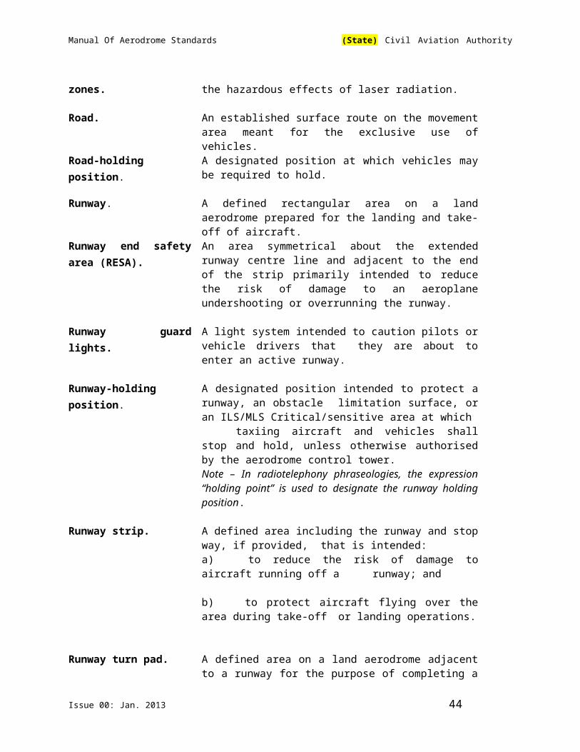
Manual Of Aerodrome Standards (State) Civil Aviation Authority
(a) the pavement classification number (PCN);
(b) pavement type for ACN-PCN determination;
(c) sub-grade strength category;
(d) maximum allowable tyre pressure category or maximum allowable tyre pressure value; and
(e) evaluation method.
Note – If necessary, PCNs may be published to an accuracy of one-tenth of a whole number.
2.6.3 The pavement classification number (PCN) reported shall indicate that an aircraft with an aircraft classification number (ACN) equal to or less than the reported PCN can operate on the pavement subject to any limitation on the tyre pressure, or aircraft all-up mass for specified aircraft type(s).
Note – Different PCNs may be reported if the strength of the pavement is subject to significant seasonal variation.
2.6.4 The ACN of an aircraft shall be determined in accordance with the standard procedures associated with the ACN-PCN method.
Note – The standard procedures for determining the ACN of an aircraft are given in the ICAO Aerodrome Design Manual(DOC 9157), Part 3. For convenience several aircraft types currently in use have been evaluated on rigid and flexible pavements founded on the four sub-grade categories in section 2.6.6 b) below and the results tabulated in that manual.
2.6.5 For the purposes of determining the ACN, the behaviour of a pavement shall be classified as equivalent to a rigid or flexible construction.
2.6.6 Information on pavement type for ACN-PCN determination, sub grade strength category, maximum allowable tyre pressure category and evaluation method shall be reported using the following codes:
(a) Pavement type for ACN-PCN determination: Code
Rigid pavement R
Flexible pavement F
Note – If the actual construction is composite or non-standard, include a note to that effect (See example 2 below).
(b) Sub grade strength category:
Code
Issue 00: Jan. 2013 44

Manual Of Aerodrome Standards (State) Civil Aviation Authority
High strength: characterised by K = 150 MN/m³ and A representing all K values above 120 MN/m³ for rigidpavements, and by CBR = 15 and representing allCBR values above 13 for flexible pavements.
Medium strength: characterised by K = 80 MN/m³ and Brepresenting a range in K of 60 to 120 MN/m³ for rigidpavements, and by CBR = 10 and representing arange in CBR of 8 to 13 for flexible pavements.
Low strength: characterised by K = 40 MN/m³ and Crepresenting a range in K of 25 to 60 MN/m³ for rigidpavements, and by CBR = 6 and representing a rangein CBR of 4 to 8 for flexible pavements.
Ultra low strength: characterised by K = 20 MN/m³ and Drepresenting all K values below 25 MN/m³ for rigidpavements, and by CBR = 3 and representing all CBRvalues below 4 for flexible pavements.
(c) Maximum allowable tyre pressure category: Code
High : no pressure limit WMedium: pressure limited to 1.50 MPa XLow: pressure limited to 1.00 MPa YVery low: pressure limited to 0.50 MPa Z
(d) Evaluation method: Code
Technical evaluation: representing a specific study of Tthe pavement characteristics and application ofpavement behaviour technology.
Using aircraft experience: representing a knowledge Uof the specific type and mass of aircraft satisfactorilybeing supported under regular use.
Note – The following examples illustrate how pavement strength data are reported under the ACN-PCN method.
Example 1 – If the bearing strength of a rigid pavement, resting on a medium strength sub grade, has been assessed by technical evaluation to be PCN 80 and there is no tyre pressure limitation, then the reported information would be:
PCN 80/ R / B / W / T
Issue 00: Jan. 2013 45

Manual Of Aerodrome Standards (State) Civil Aviation Authority
Example 2 – If the bearing strength of a composite pavement, behaving like a flexible pavement and resting on a high strength sub grade, has been assessed using aircraft experience to be PCN 50 and the maximum tyre pressure allowable is 1.00 MPa, then the reported information would be:
PCN 50/ F / A / Y / U
Note.— Composite construction.
Example 3 – If the bearing strength of a flexible pavement, resting on a medium strength sub grade, has been assessed by technical evaluation to be PCN 40 and the maximum allowable tyre pressure is 0.80 MPa, then the reported information would be:
PCN 40 / F / B / 0.80 MPa / T
Example 4 – If a pavement is subject to a B747-400 all-up mass limitation of 390 000 kg, then the reported information would include the following note.
Note – The reported PCN is subject to a B747-400 all-up mass limitation of 390 000 kg.
2.6.7 Criteria shall be established to regulate the use of a pavement by an aircraft with an ACN higher than the PCN reported for that pavement in accordance with sections 2.6.2 and 2.6.3.
Note – Attachment A, Section 19 details a simple method for regulating overload operations while the ICAO Aerodrome Design Manual(Doc 9157), Part 3 includes the descriptions of more detailed procedures for evaluation of pavements and their suitability for restricted overload operations.
2.6.8 The bearing strength of a pavement intended for aircraft of apron (ramp) mass equal to or less than 5700 kg shall be made available by reporting the following information:
(a) maximum allowable aircraft mass; and
(b) maximum allowable tyre pressure.
Example: 4 000 kg/0.50 MPa.
2.7 Pre-Flight Altimeter Check Location
2.7.1 One or more pre-flight altimeter check locations shall be established for an aerodrome.
2.7.2 Recommendation — A pre-flight check location should be located on an apron.
Issue 00: Jan. 2013 46

Manual Of Aerodrome Standards (State) Civil Aviation Authority
Note 1 – Locating a pre-flight altimeter location on an apron enables an altimeter check to be made prior to obtaining taxi clearance and eliminates the need for stopping for that purpose after leaving the apron.
Note 2 – Normally an entire apron can serve as a satisfactory altimeter check location.
2.7.3 The elevation of a pre-flight altimeter check location shall be given as the average elevation, rounded to the nearest metre, of the area on which it is located. The elevation of any portion of a pre-flight altimeter check location shall be within 3m of the average elevation for that location.
2.8 Declared Distances
2.8.1 The following distances shall be calculated to the nearest meter for a runway intended for use by international commercial air transport:
(a) take-off run available;
(b) take-off distance available;
(c) accelerate-stop distance available; and
(d) landing distance available.
Note – Guidance on calculation of declared distances is given in Attachment A, Section 3.
2.9 Conditions of the Movement Area and Related Facilities
2.9.1 Information on the condition of the movement area and the operational status of related facilities shall be provided to the Aeronautical Information Services and similar information of operational significance to the air traffic service units, to enable those units to provide the necessary information to arriving and departing aircraft. The information shall be kept up to date and changes in conditions reported without delay.
2.9.2 The condition of the movement area and the operational status of related
facilities shall be monitored and reports on matters of operational significance or affecting aircraft performance given, particularly in respect of the following:
(a) construction or maintenance work;
(b) rough or broken surfaces on a runway, taxiway or an apron;
(c) water on a runway, a taxiway or an apron;
(d) other temporary hazards, including parked aircraft;
Issue 00: Jan. 2013 47

Manual Of Aerodrome Standards (State) Civil Aviation Authority
(e) failure or irregular operation of part of all of the aerodrome visual aids; and
(f) failure of the normal or secondary power supply.
2.9.3 To facilitate compliance with sections 2.9.1 and 2.9.2, inspections of the movement area shall be carried out each day at least once where the code number is 1 or 2 and at least twice where the code number is 3 or 4.
Note – Guidance on carrying out daily inspections of the movement area is given in the ICAO Airport Services Manual (Doc 9137), Part 8 and in the Manual of Surface Movement Guidance and Control Systems (SMGCS) (Doc 9474).
Water on a Runway
2.9.4 Whenever water is present on a runway, a description of the runway surface conditions on the centre half of the width of the runway, including the possible assessment of water depth, where applicable, shall be made available using the following terms:
DAMP – the surface shows a change of colour due to moisture.
WET – the surface is soaked but there is no standing water.
WATER PATCHES – significant patches of standing water are visible.
FLOODED – extensive standing water is visible.
2.9.5 Information that a runway or portion thereof may be slippery when wet shall be made available.
2.9.6 A runway or portion thereof shall be determined as being slippery when wet when the measurements specified in Chapter 10, 10.2.3 show that the runway surface friction characteristics as measured by a continuous friction measuring device are below the minimum friction level specified in this Manual.
Note – Guidance on determining and expressing the minimum friction level is provided in Attachment A, Section 7.
2.9.7 Information on the minimum friction level specified in this Manual for reporting
slippery runway conditions and the type of friction measuring device used shall be made available.
2.9.8 Recommendation — When it is suspected that a runway may become slippery under unusual conditions, then additional measurements should be made when such conditions occur, and information on the runway surface friction characteristics made available when these additional measurements show that the runway or a portion thereof has become slippery.
2.9.9 Not applicable
Issue 00: Jan. 2013 48

Manual Of Aerodrome Standards (State) Civil Aviation Authority
2.9.10 Not applicable
2.9.11 Not applicable
2.10 Disabled Aircraft Removal
Note – See Chapter 9, 9.2.3 of this Manual for information on disabled aircraft removal services.
2.10.1 The telephone/fax number(s) of the office of the aerodrome coordinator of operations for the removal of an aircraft disabled on or adjacent to the movement area shall be made available to aircraft operators.
2.10.2 Recommendation - Information concerning the capability to remove an aircraft disabled on or adjacent to the movement area shall be made available.
Note – The capability to remove a disabled aircraft may be expressed in terms of the largest type of aircraft which the aerodrome is equipped to remove.
2.11 Rescue and Fire Fighting
Note – See Chapter 9,9.2.2 of this Manual for information on rescue and fire fighting services.
2.11.1 Information concerning the level of protection provided at an aerodrome for aircraft rescue and fire fighting purposes shall be made available.
2.11.2 The level of protection normally available at the aerodrome shall be expressed in terms of the category of the rescue and fire fighting services as described in Chapter 9,9.2.2 of this Manual and in accordance with the types and amounts of extinguishing agents normally available at the aerodrome.
2.11.3 Changes in the level of protection normally available at an aerodrome for rescue and fire fighting shall be notified to the air traffic services unit and the Aeronautical Information Services to enable those units to provide the necessary information to arriving and departing aircraft. When such a change has been corrected, the above units shall be advised accordingly.
Note – Change in the level of protection from that normally available at the aerodrome, could result from a change in availability of extinguishing agents, equipment to deliver the agents or personnel to operate the equipment, etc.
2.11.4 A change shall be expressed in terms of the new category of the rescue and fire fighting service available at the aerodrome.
2.12 Visual Approach Slope Indicator Systems
Issue 00: Jan. 2013 49

Manual Of Aerodrome Standards (State) Civil Aviation Authority
2.12.1 The following information concerning a visual approach slope indicator system installation shall be made available:
(a) associated runway designation number;
(b) type of system according to Chapter 9, 9.2.3.5.2 of this Manual. For an AT-VASIS, PAPI or APAPI installation, the side of the runway on which the lights are installed, i.e. left or right, shall be given;
(c) where the axis of the system is not parallel to the runway centre line, the angle of displacement and the direction of displacement, i.e. left or right shall be indicated;
(d) nominal approach slope angle(s). For a T-VASIS or an AT-VASIS this shall be angle θ according to the formula in Figure 5-18 of ICAO Annex 14 Vol. I and for a PAPI and an APAPI this shall be angle (B+C) ÷ 2 and (A+B) ÷ 2, respectively as in Figure 5-20 of ICAO Annex 14 Vol. I; and
(e) minimum eye height(s) over the threshold of the on-slope signal(s). For a T-VASIS or an AT-VASIS this shall be the lowest height at which only the wing bar(s) are visible; however, the additional heights at which the wing bar(s) plus one, two or three fly down light units come into view may also be reported if such information would be of benefit to aircraft using the approach. For a PAPI this shall be the setting angle of the third unit from the runway minus 2′, i.e. angle B minus 2′, and for an APAPI this shall be the setting angle of the unit farther from the runway minus 2′, i.e. angle A minus 2′.
2.13 Coordination Between the Aerodrome Operator and Aeronautical Information Service
2.13.1 To ensure that the Aeronautical Information Services obtain information to enable them to provide up-to-date pre-flight information and to meet the need for in-flight information, the aerodrome operator shall establish arrangements with the Aeronautical Information Services to report, with a minimum of delay:
(a) information on the status of certification of aerodromes and aerodrome conditions (reference chapter 3 and sections 2.9, 2.10, 2.11, 2.12 above);
(b) the operational status of associated facilities, services and navigation aids within their area of responsibility;
(c) any other information considered to be of operational significance.
2.13.2 Before introducing changes to the air navigation system, due account shall be taken by the aerodrome operator of the time needed by the Aeronautical Information Services for the preparation, production and issue of relevant material for promulgation. To ensure timely provision of information to the
Issue 00: Jan. 2013 50

Manual Of Aerodrome Standards (State) Civil Aviation Authority
Aeronautical Information Services, close coordination between those services concerned is therefore required.
2.13.3 Of a particular importance are changes to aeronautical information that affects charts and/or computer-based navigation systems which qualify to be notified by the Aeronautical Information Regulation and Control (AIRAC) system, as specified in ICAO Annex 15, Chapter 6 and Appendix 4. The pre-determined internationally agreed AIRAC effective dates in addition to 14 days postage time shall be observed by the responsible aerodrome operator when submitting the raw information/data to the Aeronautical Information Services.
2.13.4 The aerodrome operator responsible for the provision of raw aeronautical information/data to the Aeronautical Information Services shall do that while taking into account accuracy and integrity requirements for aeronautical data as specified in Appendix 5 of this Manual.
Note 1 – Specifications for the issue of a NOTAM are contained in ICAO Annex 15, Chapter 5, Appendix 6.
Note 2 – AIRAC information is distributed by the AIS at least 42 days in advance of the AIRAC effective dates with the objective of reaching recipients at least 28 days in advance of the effective date.
Note 3 – The schedule of the predetermined internationally agreed AIRAC common effective dates at intervals of 28 days, including 19 November 2009 and guidance for the AIRAC use are contained in the ICAO Aeronautical Information Services Manual (Doc 8126, Chapter 2).
Issue 00: Jan. 2013 51
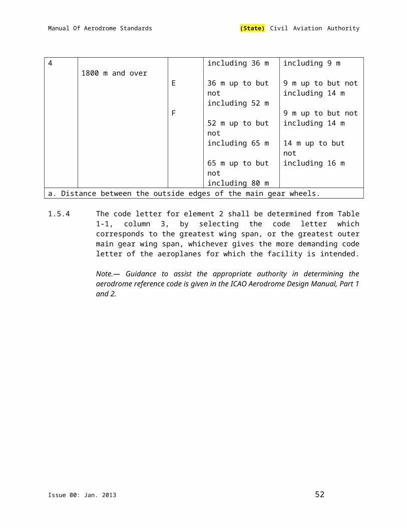
Manual Of Aerodrome Standards (State) Civil Aviation Authority
CHAPTER 3. PHYSICAL CHARACTERISTICS
3.1 Runways
Number and Orientation of Runways
Introductory Note — Many factors affect the determination of the orientation, siting and number of runways.
One important factor is the usability factor, as determined by the wind distribution, which is specified hereunder. Another important factor is the alignment of the runway to facilitate the provision of approaches conforming to the approach surface specifications of Chapter 4 of this Manual. In Attachment A, Section 1, information is given concerning these and other factors.
When a new instrument runway is being located, particular attention needs to be given to areas over which aeroplanes will be required to fly when following instrument approach and missed approach procedures, so as to ensure that obstacles in these areas or other factors will not restrict the operation of the aeroplanes for which the runway is intended.
3.1.1 The number and orientation of runways at an aerodrome shall be such that the usability factor of the aerodrome is not less than 95 per cent for the aeroplanes that the aerodrome is intended to serve.
3.1.2 Recommendation — The siting and orientation of runways at an aerodrome should, where possible, be such that the arrival and departure tracks minimize interference with areas approved for residential use and other noise-sensitive areas close to the aerodrome in order to avoid future noise problems.
Note.— Guidance on how to address noise problems is provided in the Airport Planning Manual (Doc 9184), Part 2, and in Guidance on the Balanced Approach to Aircraft Noise Management (Doc 9829).
3.1.3 Choice of Maximum Permissible Cross-Wind Components
In the application of section 3.1.1 above, it shall be assumed that landing or take-off of aeroplanes is, in normal circumstances, precluded when the cross-wind component exceeds:
— 37 km/h (20 kt) in the case of aeroplanes whose reference field length is 1 500 m or over, except that when poor runway braking action owing to an insufficient longitudinal coefficient of friction is experienced with some frequency, a cross-wind component not exceeding 24 km/h (13 kt) should be assumed;
— 24 km/h (13 kt) in the case of aeroplanes whose reference field length is 1 200 m or up to but not including 1 500 m; and
Issue 00: Jan. 2013 52
Manual Of Aerodrome Standards (State) Civil Aviation Authority
— 19 km/h (10 kt) in the case of aeroplanes whose reference field length is less than 1 200 m.
Note — In Attachment A, Section 1, guidance is given on factors affecting the calculation of the estimate of the usability factor and allowances which may have to be made to take account of the effect of unusual circumstances.
3.1.4 Data to be used
The selection of data to be used for the calculation of the usability factor shall be based on reliable wind distribution statistics that extend over as long a period as possible, preferably of not less than five years. The observations used should be made at least eight times daily and spaced at equal intervals of time.
Note — These winds are mean winds. Reference to the need for some allowance for gusty conditions is made in Attachment A, Section 1.
Location of threshold
3.1.5 A threshold shall normally be located at the extremity of a runway unless operational considerations justify the choice of another location.
Note — Guidance on the siting of the threshold is given in Attachment A, Section 10.
3.1.6 When it is necessary to displace a threshold, either permanently or temporarily, from its normal location, account shall be taken of the various factors which may have a bearing on the location of the threshold. Where this displacement is due to an unserviceable runway condition, a cleared and graded area of at least 60 m in length shall be available between the unserviceable area and the displaced threshold. Additional distance shall also be provided to meet the requirements of the runway end safety area as appropriate.
Note — Guidance on factors which may be considered in the determination of the location of a displaced threshold is given in, Attachment A, Section 10.
Actual Length of Runways
3.1.7 Primary Runway
Except as provided in section 3.1.9 of this Part, the actual runway length to be provided for a primary runway shall be adequate to meet the operational requirements of the aeroplanes for which the runway is intended and shall be not less than the longest length determined by applying the corrections for local conditions to the operations and performance characteristics of the relevant aeroplanes.
Note 1 — This specification does not necessarily mean providing for operations by the critical aeroplane at its maximum mass.
Issue 00: Jan. 2013 53

Manual Of Aerodrome Standards (State) Civil Aviation Authority
Note 2 — Both take-off and landing requirements need to be considered when determining the length of runway to be provided and the need for operations to be conducted in both directions of the runway.
Note 3 — Local conditions that may need to be considered include elevation, temperature, runway slope, humidity and the runway surface characteristics.
Note 4 — When performance data on aeroplanes for which the runway is intended are not known, guidance on the determination of the actual length of a primary runway by application of general correction factors is given in the ICAO Aerodrome Design Manual(Doc 9157), Part 1.
3.1.8 Secondary Runway
The length of a secondary runway shall be determined similarly to primary runways except that it needs only to be adequate for those aeroplanes which require to use that secondary runway in addition to the other runway or runways in order to obtain a usability factor of at least 95 per cent.
3.1.9 Runways with Stop ways or Clearways
Where a runway is associated with a stop way or clearway, an actual runway length less than that resulting from application of sections 3.1.7 or 3.1.8, as appropriate, may be considered satisfactory, but in such a case any combination of runway, stop way and clearway provided shall permit compliance with the operational requirements for take-off and landing of the aeroplanes the runway is intended to serve.
Note — Guidance on use of stop ways and clearways is given in , Attachment A, Section 2.
Width of Runways
3.1.10 The width of a runway shall not be less than the appropriate dimension specified in the following tabulation:
Code letterCodeNumber
A B C D E F
1a 18 m 18 m 23 m - - -2a 23 m 23 m 30 m - - -3 30 m 30 m 30 m 45 m - -4 - - 45 m 45 m 45 m 60 m
a. The width of a precision approach runway should be not less than 30 m where the code number is 1 or 2.
Issue 00: Jan. 2013 54

Manual Of Aerodrome Standards (State) Civil Aviation Authority
Note 1 — The combinations of code numbers and letters for which widths are specified have been developed for typical aeroplane characteristics.
Note 2 — Factors affecting runway width are given in the ICAO Aerodrome Design Manual(Doc 9157), Part 1.
Minimum Distance between Parallel Runways
3.1.11 Where parallel non-instrument runways are intended for simultaneous use, the minimum distance between their centre lines shall be:
— 210 m where the higher code number is 3 or 4;
— 150 m where the higher code number is 2; and
— 120 m where the higher code number is 1.
Note — Procedures for wake turbulence categorization of aircraft and wake turbulence separation minima are contained in the Procedures for Air Navigation Services — Air Traffic Management (PANS-ATM), Doc 4444, Chapter 4, 4.9 and Chapter 5,5.8, respectively.
3.1.12 Where parallel instrument runways are intended for simultaneous use subject to conditions specified in the PANS-ATM (Doc 4444) and the PANS-OPS (Doc 8168), Volume I, the minimum distance between their centre lines shall be:
— 1 035 m for independent parallel approaches;
— 915 m for dependent parallel approaches;
— 760 m for independent parallel departures;
— 760 m for segregated parallel operations;
except that:
(a) for segregated parallel operations the specified minimumdistance:
(1) may be decreased by 30 m for each 150 m that the arrival runway is staggered toward the arriving aircraft, to a minimum of 300 m; and
(2) should be increased by 30 m for each 150 m that the arrival runway is staggered away from the arriving aircraft;
(b) for independent parallel approaches, combinations of minimum distances and associated conditions other than those specified in the PANS-ATM (Doc 4444) may be applied when it is determined that such combinations would not adversely affect the safety of aircraft operations.
Issue 00: Jan. 2013 55

Manual Of Aerodrome Standards (State) Civil Aviation Authority
Note.— Procedures and facilities requirements for simultaneous operations on parallel or near-parallel instrument runways are contained in the PANS-ATM (Doc 4444), Chapter 6 and the PANS-OPS (Doc 8168), Volume I, Part III, Section 2, and Volume II, Part I, Section 3; Part II, Section 1; and Part III, Section 3, and relevant guidance is contained in the Manual on Simultaneous Operations on Parallel or Near-Parallel Instrument Runways (SOIR) (Doc 9643).
Slopes on Runways
3.1.13 Longitudinal Slopes
The slope computed by dividing the difference between the maximum and minimum elevation along the runway centre line by the runway length shall not exceed:
— 1 per cent where the code number is 3 or 4; and
— 2 per cent where the code number is 1 or 2.
3.1.14 An operator shall not allow any portion of a runway to exceed the longitudinal slopes stipulated as follows:
— 1.25 per cent where the code number is 4, except that for the first and last quarter of the length of the runway the longitudinal slope should not exceed 0.8 per cent;
— 1.5 per cent where the code number is 3, except that for the first and last quarter of the length of a precision approach runway category II or III the longitudinal slope should not exceed 0.8 per cent; and
— 2 per cent where the code number is 1 or 2. 3.1.15 Longitudinal Slope Changes
Where slope changes cannot be avoided, a slope change between two consecutive slopes shall not exceed:
— 1.5 per cent where the code number is 3 or 4; and
— 2 per cent where the code number is 1 or 2.
Note — Guidance on slope changes before a runway is given in Attachment A, Section 4.
3.1.16 Recommendation — The transition from one slope to another should be accomplished by a curved surface with a rate of change not exceeding:
— 0.1 per cent per 30 m (minimum radius of curvature of 30 000 m) where the code number is 4;
Issue 00: Jan. 2013 56
Manual Of Aerodrome Standards (State) Civil Aviation Authority
— 0.2 per cent per 30 m (minimum radius of curvature of 15 000 m) where the code number is 3; and
— 0.4 per cent per 30 m (minimum radius of curvature of 7 500 m) where the code number is 1 or 2.
3.1.17 Sight Distance
Where slope changes cannot be avoided, they shall be such that there will be an unobstructed line of sight from:
— any point 3 m above a runway to all other points 3 m above the runway within a distance of at least half the length of the runway where the code letter is C, D, E or F.
— any point 2 m above a runway to all other points 2 m above the runway within a distance of at least half the length of the runway where the code letter is B; and
— any point 1.5 m above a runway to all other points 1.5 m above the runway within a distance of at least half the length of the runway where the code letter is A.
Note — Consideration will have to be given to providing an unobstructed line of sight over the entire length of a single runway where a full-length parallel taxiway is not available. Where an aerodrome has intersecting runways, additional criteria on the line of sight of the intersection area would need to be considered for operational safety. See the ICAO Aerodrome Design Manual, (Doc 9157),Part 1.
3.1.18 Distance between Slope Changes
Undulations or appreciable changes in slopes located close together along a runway shall be avoided. The distance between the points of intersection of two successive curves shall not be less than:
(a) the sum of the absolute numerical values of the correspondingslope changes multiplied by the appropriate value as follows:
— 30 000 m where the code number is 4;
— 15 000 m where the code number is 3; and
— 5 000 m where the code number is 1 or 2; or
(b) 45 m; whichever is greater.
Issue 00: Jan. 2013 57

Manual Of Aerodrome Standards (State) Civil Aviation Authority
Note — Guidance on implementing this specification is given in Attachment A, Section 4.
3.1.19 Transverse Slopes
To promote the most rapid drainage of water, the runway surface shall, if practicable, be cambered except where a single cross fall from high to low in the direction of the wind most frequently associated with rain would ensure rapid drainage. The transverse slope should ideally be:
— 1.5 per cent when the code letter is C, D, E or F;
— 2 per cent when the code letter is A or B;
but in any event should not exceed 1.5 per cent or 2 per cent, as applicable, nor be less than 1 per cent except at runway or taxiway intersections where flatter slopes may be necessary.
For a cambered surface the transverse slope on each side of the centre line should be symmetrical.
Note — On wet runways with cross-wind conditions the problem of aquaplaning from poor drainage is apt to be accentuated. In Attachment A, Section 7, information is given concerning this problem and other relevant factors.
3.1.20 The transverse slope shall be substantially the same throughout the length of a
runway except at an intersection with another runway or a taxiway where an even transition shall be provided taking account of the need for adequate drainage.
Note — Guidance on transverse slope is given in the ICAO Aerodrome Design Manual(Doc 9157), Part 3.
Strength of Runways
3.1.21 A runway shall be capable of withstanding the traffic of aeroplanes the runway is intended to serve.
Surface of Runways
3.1.22 The surface of a runway shall be constructed without irregularities that would result in loss in friction characteristics or otherwise adversely affect the take-off or landing of an aeroplane.
Note 1 — Surface irregularities may adversely affect the take-off or landing of an aeroplane by causing excessive bouncing, pitching, vibration, or other difficulties in the control of an aeroplane.
Issue 00: Jan. 2013 58

Manual Of Aerodrome Standards (State) Civil Aviation Authority
Note 2 — Guidance on design tolerances and other information is given in Attachment A, Section 5. Additional guidance is included in the ICAO Aerodrome Design Manual(Doc 9157), Part 3.
3.1.23 The surface of a paved runway shall be so constructed as to provide good friction characteristics when the runway is wet.
3.1.24 Measurements of the friction characteristics of a new or resurfaced runway shall be made with a continuous friction measuring device using self-wetting features in order to assure that the design objectives with respect to its friction characteristics have been achieved.
Note — Guidance on friction characteristics of new runway surfaces is given in Attachment A, Section 7. Additional guidance is included in the ICAO Airport Services Manual(Doc 9137), Part 2.
3.1.25 Recommendation — The average surface texture depth of a new surface should be not less than 1.0 mm.
Note 1 — This normally requires some form of special surface treatment.
Note 2 — Guidance on methods used to measure surface texture is given in the ICAO Airport Services Manual(Doc 9137), Part 2.
3.1.26 Recommendation — When the surface is grooved or scored, the grooves or
scorings should be either perpendicular to the runway centre line or parallel to non-perpendicular transverse joints, where applicable.
Note — Guidance on methods for improving the runway surface texture is given in the ICAO Aerodrome Design Manual(Doc 9157, Part 3.
3.2. Runway Shoulders
General
Note — Guidance on characteristics and treatment of runway shoulders is given in Attachment A, Section 8, and in the ICAO Aerodrome Design Manual (Doc 9157), Part 1.
3.2.1 Runway shoulders shall be provided for a runway where the code letter is D or E, and the runway width is less than 60 m.
3.2.2 Runway shoulders shall be provided for a runway where the code letter is F.
Width of runway shoulders
3.2.3 The runway shoulders shall extend symmetrically on each side of the runway so that the overall width of the runway and its shoulders is not less than:
Issue 00: Jan. 2013 59

Manual Of Aerodrome Standards (State) Civil Aviation Authority
— 60 m where the code letter is D or E; and
— 75 m where the code letter is F.
Slopes on Runway Shoulders
3.2.4 The surface of the shoulder that abuts the runway shall be flush with the surface of the runway and its transverse slope should not exceed 2.5 per cent.
Strength of Runway Shoulders
3.2.5 A runway shoulder shall be prepared or constructed so as to be capable, in the event of an aeroplane running off the runway, of supporting the aeroplane without inducing structural damage to the aeroplane and of supporting ground vehicles which may operate on the shoulder.
Note — Guidance on strength of runway shoulders is given in the ICAO Aerodrome Design Manual(Doc 9157), Part 1.
3.3 Runway Turn Pads
General
3.3.1 Where the end of a runway is not served by a taxiway or a taxiway turnaround and where the code letter is D, E or F, a runway turn pad shall be provided to facilitate a 180-degree turn of aeroplanes. (See Figure 3-1)
3.3.2 Recommendation — Where the end of a runway is not served by a taxiway or a taxiway turnaround and where the code letter is A, B or C, a runway turn pad should be provided to facilitate a 180-degree turn of aeroplanes.
Note 1.— Such areas may also be useful if provided along a runway to reduce taxiing time and distance for aeroplanes which may not require the full length of the runway.
Note 2.— Guidance on the design of the runway turn pads is available in the Aerodrome Design Manual(Doc 9157), Part 1. Guidance on taxiway turnaround as an alternate facility is available in the Aerodrome Design Manual(Doc 9157) Part 2.
3.3.3 Recommendation — The runway turn pad may be located on either the left or right side of the runway and adjoining the runway pavement at both ends of the runway and at some intermediate locations where deemed necessary.
Note.— The initiation of the turn would be facilitated by locating the turn pad on the left side of the runway, since the left seat is the normal position of the pilot-in-command.
Issue 00: Jan. 2013 60
Manual Of Aerodrome Standards (State) Civil Aviation Authority
3.3.4 Recommendation.— The intersection angle of the runway turn pad with the runway should not exceed 30 degrees.
3.3.5 Recommendation.— The nose wheel steering angle to be used in the design of the runway turn pad should not exceed 45 degrees.
3.3.6 The design of a runway turn pad shall be such that, when the cockpit of the aeroplane for which the turn pad is intended remains over the turn pad marking, the clearance distance between any wheel of the aeroplane landing gear and the edge of the turn pad shall be not less than that given by the following tabulation:
Code Letter ClearanceA 1.5mB 2.25mC 3 m if the turn pad is intended to be used by
aeroplanes with a wheelbase less than 18 m;
4.5 m if the turn pad is intended to be used by aeroplanes with a wheelbase equal to or greater than 18 m.
D 4.5mE 4.5mF 4.5m
Note.— Wheel base means the distance from the nose gear to the geometric centre of the main gear.
3.3.7 Recommendation — Where severe weather conditions and resultant lowering of surface friction characteristics prevail, a larger wheel-to-edge clearance of 6 m should be provided where the code letter is E or F.
Slopes on Runway Turn Pads
3.3.8 Recommendation — The longitudinal and transverse slopes on a runway turn pad should be sufficient to prevent the accumulation of water on the surface and facilitate rapid drainage of surface water. The slopes shall be the same as those on the adjacent runway pavement surface.
Strength of Runway Turn Pads
3.3.9 Recommendation — The strength of a runway turn pad shall be at least equal to that of the adjoining runway which it serves, due consideration being given to the fact that the turn pad will be subjected to slow-moving traffic making hard turns and consequent higher stresses on the pavement.
Note.— Where a runway turn pad is provided with flexible pavement, the surface would need to be capable of withstanding the horizontal shear forces exerted by the main landing gear tyres during turning manoeuvres.
Issue 00: Jan. 2013 61
Manual Of Aerodrome Standards (State) Civil Aviation Authority
Surface of Runway Turn Pads
3.3.10 The surface of a runway turn pad shall not have surface irregularities that may cause damage to an aeroplane using the turn pad.
3.3.11 Recommendation.— The surface of a runway turn pad should be so constructed as to provide good friction characteristics for aeroplanes using the facility when the surface is wet.
Shoulders for Runway Turn Pads
3.3.12 Recommendation — The runway turn pads should be provided with shoulders of such width as is necessary to prevent surface erosion by the jet blast of the most demanding aeroplane for which the turn pad is intended, and any possible foreign object damage to the aeroplane engines.
Note.— As a minimum, the width of the shoulders would need to cover the outer engine of the most demanding aeroplane and thus may be wider than the associated runway shoulders.
3.3.13 Recommendation — The strength of runway turn pad shoulders shouldl be capable of withstanding the passage of the aeroplane it is designed to serve without inducing structural damage to the aeroplane and to the supporting ground vehicles that may operate on the shoulder.
3.4 Runway Strips
General
3.4.1 A runway and any associated stop ways shall be included in a strip.
Length of Runway Strips
3.4.2 A strip shall extend before the threshold and beyond the end of the runway or stop way for a distance of at least:
— 60 m where the code number is 2, 3 or 4;
— 60 m where the code number is 1 and the runway is an instrument one; and
— 30 m where the code number is 1 and the runway is a non-instrument one.
Width of Runway Strips
3.4.3 A strip including a precision approach runway shall, wherever practicable, extend laterally to a distance of at least:
Issue 00: Jan. 2013 62

Manual Of Aerodrome Standards (State) Civil Aviation Authority
— 150 m where the code number is 3 or 4; and
— 75 m where the code number is 1 or 2;
on each side of the centre line of the runway and its extended centre line throughout the length of the strip.
3.4.4 A strip including a non-precision approach runway shall extend laterally to a distance of at least:
— 150 m where the code number is 3 or 4; and
— 75 m where the code number is 1 or 2;
on each side of the centre line of the runway and its extended centre line throughout the length of the strip.
3.4.5 A strip including a non-instrument runway shall extend on each side of the centre line of the runway and its extended centre line throughout the length of the strip, to a distance of at least:
— 75 m where the code number is 3 or 4;
— 40 m where the code number is 2; and
— 30 m where the code number is 1.
Objects on Runway Strips
Note — See Attachment A section 13.2.9 of this Manual for information regarding siting and construction of equipment and installations on runway strips.
3.4.6 An object situated on a runway strip which may endanger aeroplanes shall be regarded as an obstacle and shall, as far as practicable, be removed.
3.4.7 No fixed object, other than visual aids required for air navigation purposes and satisfying the relevant frangibility requirement in Chapter 5 of this Manual shall be permitted on a runway strip:
(a) within 77.5 m of the runway centre line of a precision approach runway category I, II or III where the code number is 4 and the code letter is F; or
(b) within 60 m of the runway centre line of a precision approach runway category I, II or III where the code number is 3 or 4; or
(c) within 45 m of the runway centre line of a precision approach runway category I where the code number is 1 or 2.
No mobile object shall be permitted on this part of the runway strip during the use of the runway for landing or take-off.
Issue 00: Jan. 2013 63

Manual Of Aerodrome Standards (State) Civil Aviation Authority
Grading of Runway Strips
3.4.8 That portion of a strip of an instrument runway within a distance of at least:
— 75 m where the code number is 3 or 4; and
— 40 m where the code number is 1 or 2;
from the centre line of the runway and its extended centre line shall provide a graded area for aeroplanes which the runway is intended to serve in the event of an aeroplane running off the runway.
Note — Guidance on grading of a greater area of a strip including a precision approach runway where the code number is 3 or 4 is given in Attachment A, Section 8.
3.4.9 That portion of a strip of a non-instrument runway within a distance of at least:
— 75 m where the code number is 3 or 4;
— 40 m where the code number is 2; and
— 30 m where the code number is 1;
from the centre line of the runway and its extended centre line shall provide a graded area for aeroplanes which the runway is intended to serve in the event of an aeroplane running off the runway.
3.4.10 The surface of that portion of a strip that abuts a runway, shoulder or stopway shall be flush with the surface of the runway, shoulder or stopway.
3.4.11 That portion of a strip to at least 30 m before a threshold shall be prepared against blast erosion in order to protect a landing aeroplane from the danger of an exposed edge.
Slopes on Runway Strips
3.4.12 Longitudinal Slopes
A longitudinal slope along that portion of a strip to be graded shall not exceed:
— 1.5 per cent where the code number is 4;
— 1.75 per cent where the code number is 3; and
— 2 per cent where the code number is 1 or 2.
3.4.13 Longitudinal Slope Changes
Issue 00: Jan. 2013 64

Manual Of Aerodrome Standards (State) Civil Aviation Authority
Slope changes on that portion of a strip to be graded shall be as gradual as practicable and abrupt changes or sudden reversals of slopes avoided.
3.4.14 Transverse Slopes
Transverse slopes on that portion of a strip to be graded shall be adequate to prevent the accumulation of water on the surface but should not exceed:
— 2.5 per cent where the code number is 3 or 4; and
— 3 per cent where the code number is 1 or 2;
except that to facilitate drainage the slope for the first 3m outward from the runway, shoulder or stop way edge shall be negative as measured in the direction away from the runway and may be as great as 5 per cent.
3.4.15 The transverse slopes of any portion of a strip beyond that to be graded shall not exceed an upward slope of 5 per cent as measured in the direction away from the runway.
Strength of Runway Strips
3.4.16 That portion of a strip of an instrument runway within a distance of at least:
75 m where the code number is 3 or 4; and
40 m where the code number is 1 or 2;
from the centre line of the runway and its extended centre line shall be so prepared or constructed as to minimize hazards arising from differences in load bearing capacity to aeroplanes which the runway is intended to serve in the event of an aeroplane running off the runway.
Note — Guidance on preparation of runway strips is given in the ICAO Aerodrome Design Manual(Doc 9157), Part 1.
3.4.17 That portion of a strip containing a non-instrument runway within a distance of at least:
— 75 m where the code number is 3 or 4;
— 40 m where the code number is 2; and
— 30 m where the code number is 1;
from the centre line of the runway and its extended centre line shall be so prepared or constructed as to minimize hazards arising from differences in load bearing capacity to aeroplanes which the runway is intended to serve in the event of an aeroplane running off the runway.
Issue 00: Jan. 2013 65

Manual Of Aerodrome Standards (State) Civil Aviation Authority
3.5 Runway End Safety Areas
General
3.5.1 A runway end safety area shall be provided at each end of a runway strip where:
— the code number is 3 or 4; and
— the code number is 1 or 2 and the runway is an instrument one.
Note — Guidance on runway end safety areas is given in Attachment A Section 9.
Dimensions of Runway End Safety Areas
3.5.2 A runway end safety area shall extend from the end of a runway strip to a distance of at least 90 m.
3.5.3 Recommendation — A runway end safety area should, as far as practicable, extend from the end of a runway strip to a distance of at least:
240 m where the code number is 3 or 4; and
— 120 m where the code number is 1 or 2. 3.5.4 The width of a runway end safety area shall be at least twice that of the
associated runway.
3.5.5 Recommendation — The width of a runway end safety area should, wherever practicable, be equal to that of the graded portion of the associated runway strip.
Objects on Runway End Safety Areas
Note — See section 9.2.9 of this Part for information regarding siting and construction of equipment and installations on runway end safety areas.
3.5.6 An object situated on a runway end safety area which may endanger aeroplanes shall be regarded as an obstacle and shall be removed.
Clearing and Grading of Runway End Safety Areas
3.5.7 A runway end safety area shall provide a cleared and graded area for aeroplanes which the runway is intended to serve in the event of an aeroplane undershooting or overrunning the runway.
Note — The surface of the ground in the runway end safety area does not need to be prepared to the same quality as the runway strip. See, however, section 3.5.11 of this Part.
Issue 00: Jan. 2013 66
Manual Of Aerodrome Standards (State) Civil Aviation Authority
Slopes on Runway End Safety Areas
3.5.8 General
The slopes of a runway end safety area shall be such that no part of the runway end safety area penetrates the approach or take-off climb surface.
3.5.9 Longitudinal Slopes
The longitudinal slopes of a runway end safety area shall not exceed a downward slope of 5 per cent. Longitudinal slope changes shall be as gradual as practicable and abrupt changes or sudden reversals of slopes avoided.
3.5.10 Transverse Slopes
The transverse slopes of a runway end safety area shall not exceed an upward or downward slope of 5 per cent. Transitions between differing slopes should be as gradual as practicable.
Strength of Runway End Safety Areas
3.5.11 A runway end safety area shall be so prepared or constructed as to reduce the risk of damage to an aeroplane undershooting or overrunning the runway, enhance aeroplane deceleration and facilitate the movement of rescue and fire fighting vehicles as required in sections 9.2.30 to 9.2.32. of this Part.
Note — Guidance on strength of a runway end safety area is given in the ICAO Aerodrome Design Manual(Doc 9157), Part 1.
3.6 Clearways
Note — The inclusion of detailed specifications for clearways in this section is not intended to imply that a clearway has to be provided. Attachment A, Section 2 provides information on the use of clearways.
Location of Clearways
3.6.1 The origin of a clearway shall be at the end of the take-off run available.
Length of Clearways
3.6.2 The length of a clearway shall not exceed half the length of the take-off run available.
Width of Clearways
Issue 00: Jan. 2013 67

Manual Of Aerodrome Standards (State) Civil Aviation Authority
3.6.3 Recommendation — A clearway should extend laterally to a distance of at least 75 m on each side of the extended centre line of the runway.
Slopes on Clearways
3.6.4 The ground in a clearway shall not project above a plane having an upward slope of 1.25 per cent, the lower limit of this plane being a horizontal line which:
(a) is perpendicular to the vertical plane containing the runway centre line; and
(b) passes through a point located on the runway centre line at the end of the take-off run available.
Note — Because of transverse or longitudinal slopes on a runway, shoulder or strip, in certain cases the lower limit of the clearway plane specified above may be below the corresponding elevation of the runway, shoulder or strip. It is not intended that these surfaces be graded to conform with the lower limit of the clearway plane nor is it intended that terrain or objects which are above the clearway plane beyond the end of the strip but below the level of the strip be removed unless it is considered they may endanger aeroplanes.
3.6.5 Abrupt upward changes in slope shall be avoided when the slope on the ground in a clearway is relatively small or when the mean slope is upward. In such situations, in that portion of the clearway within a distance of 22.5 m or half the runway width whichever is greater on each side of the extended centre line, the slopes, slope changes and the transition from runway to clearway should conform with those of the runway with which the clearway is associated.
Objects on clearways
Note — See Atechment A 13.2.9 of this Manual for information regarding siting and construction of equipment and installations on clearways.
3.6.6 An object situated on a clearway which may endanger aeroplanes in the air shall be regarded as an obstacle and shall be removed.
3.7 Stopways
Note — The inclusion of detailed specifications for stopways in this section is not intended to imply that a stopway has to be provided. Attachment A, Section 2 provides information on the use of stopways.
Width of Stopways
3.7.1 A stop way shall have the same width as the runway with which it is associated.
Slopes on Stopways
Issue 00: Jan. 2013 68

Manual Of Aerodrome Standards (State) Civil Aviation Authority
3.7.2 Slopes and changes in slope on a stopway, and the transition from a runway to a stopway, shall comply with the specifications of sections 3.1.13 to 3.1.19 of this Manual for the runway with which the stopway is associated except that:
(a) the limitation in section 7.2.1.14 of this Manual of a 0.8 per cent slope for the first and last quarter of the length of a runway need not be applied to the stopway; and
(a) at the junction of the stopway and runway and along the stopway the maximum rate of slope change may be 0.3per cent per 30 m (minimum radius of curvature of 10 000 m) for a runway where the code number is 3 or 4.
Strength of Stopways
3.7.3 A stopway shall be prepared or constructed so as to be capable, in the event of an abandoned take-off, of supporting the aeroplane which the stopway is intended to serve without inducing structural damage to the aeroplane.
Note — Attachment A, Section 2 presents guidance relative to the support capability of a stopway.
Surface of Stopways
3.7.4 The surface of a paved stopway shall be so constructed as to provide a good coefficient of friction to be compatible with that of the associated runway when the stopway is wet.
3.7.5 The friction characteristics of an unpaved stopway shall not be substantially less than that of the runway with which the stopway is associated.
3.8 Radio Altimeter Operating Area
General
3.8.1 Recommendation — A radio altimeter operating area should be established in the pre-threshold area of a precision approach runway.
Length of the Area
3.8.2 Recommendation — A radio altimeter operating area should extend before the threshold for a distance of at least 300 m.
Width of the Area
3.8.3 Recommendation — A radio altimeter operating area should extend laterally, on each side of the extended centre line of the runway, to a distance of 60 m, except that, when special circumstances so warrant, the distance may be reduced to no
Issue 00: Jan. 2013 69

Manual Of Aerodrome Standards (State) Civil Aviation Authority
less than 30 m if an aeronautical study indicates that such reduction would not affect the safety of operations of aircraft.
Longitudinal Slope Changes
3.8.4 Recommendation — On a radio altimeter operating area, slope changes should be avoided or kept to a minimum. Where slope changes cannot be avoided, the slope changes should be as gradual as practicable and abrupt changes or sudden reversals of slopes avoided. The rate of change between two consecutive slopes should not exceed 2 per cent per 30 m.
Note — Guidance on radio altimeter operating area is given in, Attachment A, Section 4.3 and in the ICAO Manual of All-Weather Operations, (Doc 9365), Section 5.2. Guidance on the use of radio altimeter is given in the PANS-OPS, Volume II, Part II, Section I.
3.9 Taxiways
Note — Unless otherwise indicated the requirements in this section are applicable to all types of taxiways.
General
3.9.1 Taxiways shall be provided to permit the safe and expeditious surface movement of aircraft.
Note — Guidance on layout of taxiways is given in the ICAO Aerodrome Design Manual (Doc 9157), Part 2.
3.9.2 Recommendation — Sufficient entrance and exit taxiways for a runway should be provided to expedite the movement of aeroplanes to and from the runway and provision of rapid exit taxiways considered when traffic volumes are high.
Note — Where the end of a runway is not served by a taxiway, it may be necessary to provide additional pavement at the end of the runway for the turning of aeroplanes. Such areas may also be useful along the runway to reduce taxiing time and distance for some aeroplanes.
3.9.3 The design of a taxiway shall be such that, when the cockpit of the aeroplane for which the taxiway is intended remains over the taxiway centre line markings, the clearance distance between the outer main wheel of the aeroplane and the edge of the taxiway should be not less than that given by the following tabulation:
Code Letter ClearanceA 1.5mB 2.25mC 3 m if the taxiway is intended to be used by aeroplanes
with a wheelbase less than 18 m;
Issue 00: Jan. 2013 70

Manual Of Aerodrome Standards (State) Civil Aviation Authority
4.5 m if the taxiway is intended to be used by aeroplanes with a wheelbase equal to or greater than 18 m.
D 4.5mE 4.5mF 4.5m
Note 1 — Wheel base means the distance from the nose gear to the geometric centre of the main gear.
Note 2 — Where the code letter is F and the traffic density is high, a wheel-to-edge clearance greater than 4.5m may be provided to permit higher taxiing speeds.
3.9.4 The design of a taxiway shall be such that, when the cockpit of the aeroplane for
which the taxiway is intended remains over the taxiway centre line markings, the clearance distance between the outer main wheel of the aeroplane and the edge of the taxiway shall be not less than that given by the following tabulation:
Code Letter ClearanceA 1.5mB 2.25mC 3 m if the taxiway is intended to be used by
aeroplanes with a wheelbase less than 18 m;
4.5 m if the taxiway is intended to be used by aeroplanes with a wheelbase equal to or greater than 18 m.
D 4.5mE 4.5mF 4.5m
Note 1 — Wheel base means the distance from the nose gear to the geometric centre of the main gear.
Note 2 — Where the code letter is F and the traffic density is high, a wheel-to-edge clearance greater than 4.5 m may be provided to permit higher taxiing speeds.
Note 3.— This provision applies to taxiways first put into service on or after 20 November 2008.
Width of Taxiways
3.9.5 A straight portion of a taxiway shall have a width of not less than that given by the following tabulation:
Issue 00: Jan. 2013 71
Manual Of Aerodrome Standards (State) Civil Aviation Authority
Code Letter Taxiway widthA 7.5mB 10.5mC 15 m if the taxiway is intended to be used by
aeroplanes with a wheelbase less than 18 m;
18 m if the taxiway is intended to be used by aeroplanes with a wheelbase equal to or greater than 18 m.
D 18m if the taxiway is intended to be used by aeroplanes with an outer main gear wheel span of less than 9 m;
23m if the taxiway is intended to be used by aeroplanes with an outer main gear wheel span equal to or greater than 9 m.
E 23mF 25m
Note — Guidance on width of taxiways is given in the ICAO Aerodrome Design Manual(Doc 9157), Part 2.
3.9.6 Taxiway curves
Recommendation — Changes in direction of taxiways should be as few and small as possible. The radii of the curves should be compatible with the manoeuvring capability and normal taxiing speeds of the aeroplanes for which the taxiway is intended. The design of the curve should be such that, when the cockpit of the aeroplane remains over the taxiway centre line markings, the clearance distance between the outer main wheels of the aeroplane and the edge of the taxiway should not be less than those specified in section 3.9.3.
Note 1 — An example of widening taxiways to achieve the wheel clearance specified is illustrated in Figure 3-2 Guidance on the values of suitable dimensions is given in the ICAO Aerodrome Design Manual (Doc 9157), Part 2.
Note 2 — The location of taxiway centre line markings and lights is specified in sections 5.2.8.6 and 5.3.16.11 of this Manual.
Note 3 — Compound curves may reduce or eliminate the need for extra taxiway width.
Junctions and Intersections
3.9.7 Recommendation — To facilitate the movement of aeroplanes, fillets should be provided at junctions and intersections of taxiways with runways, aprons and other taxiways. The design of the fillets should ensure that the minimum wheel
Issue 00: Jan. 2013 72
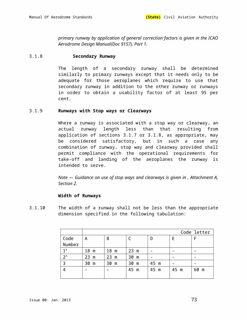
Manual Of Aerodrome Standards (State) Civil Aviation Authority
clearances specified in section 7.2.9.3 are maintained when aeroplanes are manoeuvring through the junctions or intersections.
Note — Consideration will have to be given to the aeroplane datum length when designing fillets. Guidance on the design of fillets and the definition of the term aeroplane datum length are given in the ICAO Aerodrome Design Manual (Doc 9157), Part 2.
Taxiway Minimum Separation Distances
3.9.8 The separation distance between the centre line of a taxiway and the centre line of a runway, the centre line of a parallel taxiway or an object shall not be less than the appropriate dimension specified in Table 3-1, except that it may be permissible to operate with lower separation distances at an existing aerodrome if an aeronautical study indicates that such lower separation distances would not adversely affect the safety or significantly affect the regularity of operations of aeroplanes.
Note 1 — Guidance on factors which may be considered in the aeronautical study is given in the ICAO Aerodrome Design Manual (Doc 9157), Part 2.
Note 2 — ILS and MLS installations may also influence the location of taxiways due to interferences to ILS and MLS signals by a taxiing or stopped aircraft. Information on critical and sensitive areas surrounding ILS and MLS installations is contained in ICAO Annex 10, Volume I, Attachments C and G (respectively).
Note 3 — The separation distances of Table 3-1, column 10, do not necessarily provide the capability of making a normal turn from one taxiway to another parallel taxiway. Guidance for this condition is given in the ICAO Aerodrome Design Manual (Doc 9157), Part 2.
Note 4 — The separation distance between the centre line of an aircraft stand taxi-lane and an object shown in Table 3-1, column 12, may need to be increased when jet exhaust wake velocity may cause hazardous conditions for ground servicing.
Table 3-1 – Taxiway minimum separation distances
Code letter
Distance between taxiway centre lineand runway centre line (metres)
Taxiwaycentreline totaxiwaycentreline(metres)
Taxiway,otherthanaircraftstandtaxi-lane,centreline toobject(metres)
Aircraftstandtaxi-lanecentreline toobject(metres)
Instrument runways
Code number
Non-instrument runways
Code number
1 2 3 4 1 2 3 4(1) (2) (3) (4) (5) (6) (7) (8) (9) (10) (11) (12)A 82.5 82.5 - - 37.5 47.5 - - 23.75 16.25 12
Issue 00: Jan. 2013 73

Manual Of Aerodrome Standards (State) Civil Aviation Authority
B 87 87 - - 42 52 - - 33.5 21.5 16.5C - - 168 - - - 93 - 44 26 24.5D - - 176 176 - - 101 101 66.5 40.5 36E - - - 182.5 - - - 107.5 80 47.5 42.5F - - - 190 - - - 115 97.5 57.5 50.5
Note 1 – The separation distances shown in columns (2) to (9) represent ordinary combinations of runways and taxiways. The basis for development of these distances is given in the ICAO Aerodrome Design Manual(Doc 9157), Part 2
Note 2 – The distances in columns (2) to (9) do not guarantee sufficient clearance behind a holding aeroplane to permit the passing of another aeroplane on a parallel taxiway. See ICAO Aerodrome Design Manual(Doc 9157), Part 2.
Slopes on Taxiways
3.9.9 Longitudinal Slopes
The longitudinal slope of a taxiway shall not exceed:
— 1.5 per cent where the code letter is C, D, E or F; and
— 3 per cent where the code letter is A or B.
3.9.10 Longitudinal Slope Changes
Recommendation — Where slope changes on a taxiway cannot be avoided, the transition from one slope to another slope should be accomplished by a curved surface with a rate of change not exceeding:
— 1 per cent per 30 m (minimum radius of curvature of 3 000 m) where the code letter is C, D, E or F; and
— 1 per cent per 25 m (minimum radius of curvature of 2 500 m) where the code letter is A or B.
3.9.11 Sight Distance
Recommendation — Where a change in slope on a taxiway cannot be avoided, the change should be such that, from any point:
— 3 m above the taxiway, it will be possible to see the whole surface of the taxiway for a distance of at least 300 m from that point, where the code letter is C, D, E or F;
— 2 m above the taxiway, it will be possible to see the whole surface of the taxiway for a distance of at least 200 m from that point, where the code letter is B; and
Issue 00: Jan. 2013 74

Manual Of Aerodrome Standards (State) Civil Aviation Authority
— 1.5 m above the taxiway, it will be possible to see the whole surface of the taxiway for a distance of at least 150 m from that point, where the code letter is A.
3.9.12 Transverse Slopes
The transverse slopes of a taxiway shall be sufficient to prevent the accumulation of water on the surface of the taxiway but should not exceed:
— 1.5 per cent where the code letter is C, D, E or F; and
— 2 per cent where the code letter is A or B.
Note — See section 3.13.4 of this Part regarding transverse slopes on an aircraft stand taxi-lane.
Strength of Taxiways
3.9.13 The strength of a taxiway shall be at least equal to that of the runway it serves, due consideration being given to the fact that a taxiway will be subjected to a greater density of traffic and, as a result of slow moving and stationary aeroplanes, to higher stresses than the runway it serves.
Note — Guidance on the relation of the strength of taxiways to the strength of runways is given in the ICAO Aerodrome Design Manual(Doc 9157) , Part 3.
Surface of Taxiways
3.9.14 The surface of a taxiway shall not have irregularities that cause damage to aeroplane structures.
3.9.15 Recommendation — The surface of a paved taxiway should be so constructed as to provide good friction characteristics when the taxiway is wet.
Rapid Exit Taxiways
Note — The following specifications detail requirements particular to rapid exit taxiways. See Figure 3-3. General requirements for taxiways also apply to this type of taxiway. Guidance on the provision, location and design of rapid exit taxiways is included in the ICAO Aerodrome Design Manual(Doc 9157), Part 2.
3. 9.16 A rapid exit taxiway shall be designed with a radius of turn-off curve of at least:
— 550 m where the code number is 3 or 4; and
— 275 m where the code number is 1 or 2; to enable exit speeds under wet conditions of:
— 93 km/h where the code number is 3 or 4; and
Issue 00: Jan. 2013 75
Manual Of Aerodrome Standards (State) Civil Aviation Authority
— 65 km/h where the code number is 1 or 2.
Note — The locations of rapid exit taxiways along a runway are based on several criteria described in the ICAO Aerodrome Design Manual(Doc 9157), Part 2, in addition to different speed criteria.
3.9.17 Recommendation — The radius of the fillet on the inside of the curve at a rapid exit taxiway should be sufficient to provide a widened taxiway throat in order to facilitate early recognition of the entrance and turn-off onto the taxiway.
3.9.18 Recommendation — A rapid exit taxiway should include a straight distance after the turn-off curve sufficient for an exiting aircraft to come to a full stop clear of any intersecting taxiway.
3.9.19 The intersection angle of a rapid exit taxiway with the runway shall not be greater than 45° nor less than 25° and preferably should be 30°.
Taxiways on Bridges
3.9.20 The width of that portion of a taxiway bridge capable of supporting aeroplanes, as measured perpendicularly to the taxiway centre line, shall not be less than the width of the graded area of the strip provided for that taxiway, unless a proven method of lateral restraint is provided which shall not be hazardous for aeroplanes for which the taxiway is intended.
3.9.21 Recommendation — Access should be provided to allow rescue and fire fighting vehicles to intervene in both directions within the specified response time to the largest aeroplane for which the taxiway bridge is intended.
Note — If aeroplane engines overhang the bridge structure, protection of adjacent areas below the bridge from engine blast may be required.
3.9.22 Recommendation — A bridge should be constructed on a straight section of the taxiway with a straight section on both ends of the bridge to facilitate the alignment of aeroplanes approaching the bridge.
3.10 Taxiway Shoulders
Note — Guidance on characteristics of taxiway shoulders and on shoulder treatment is given in the ICAO Aerodrome Design Manual(Doc 9157), Part 2.
3.10.1 Recommendation — Straight portions of a taxiway where the code letter is C, D, E or F should be provided with shoulders which extend symmetrically on each side of the taxiway so that the overall width of the taxiway and its shoulders on straight portions is not less than:
— 60 m where the code letter is F;
Issue 00: Jan. 2013 76

Manual Of Aerodrome Standards (State) Civil Aviation Authority
— 44 m where the code letter is E;
— 38 m where the code letter is D; and
— 25 m where the code letter is C.
On taxiway curves and on junctions or intersections where increased pavement is provided, the shoulder width should be not less than that on the adjacent straight portions of the taxiway.
3.10.2 When a taxiway is intended to be used by turbine-engine aeroplanes, the surface of the taxiway shoulder shall be so prepared as to resist erosion and the ingestion of the surface material by aeroplane engines.
3.11 Taxiway Strips
Note — Guidance on characteristics of taxiway strips is given in the ICAO Aerodrome Design Manual(Doc 9157), Part 2.
General
3.11.1 A taxiway, other than an aircraft stand taxi-lane, shall be included in a strip.
Width of Taxiway Strips
3.11.2 A taxiway strip shall extend symmetrically on each side of the centre line of the taxiway throughout the length of the taxiway to at least the distance from the centre line given in Table 3-1, column 11 of this Manual.
Objects on Taxiway Strips
Note — See section 9.2.9 of this Part for information regarding siting and construction of equipment and installations on taxiway strips.
3.11.3 The taxiway strip shall provide an area clear of objects which may endanger taxiing aeroplanes.
Note — Consideration will have to be given to the location and design of drains on a taxiway strip to prevent damage to an aeroplane accidentally running off a taxiway. Suitably designed drain covers may be required.
Grading of Taxiway Strips
3.11.4 The centre portion of a taxiway strip shall provide a graded area to a distance from the centre line of the taxiway of at least:
— 11 m where the code letter is A;
— 12.5 m where the code letter is B or C;
Issue 00: Jan. 2013 77

Manual Of Aerodrome Standards (State) Civil Aviation Authority
— 19 m where the code letter is D;
— 22 m where the code letter is E; and
— 30 m where the code letter is F.
Slopes on Taxiway Strips
3.11.5 The surface of the strip shall be flush at the edge of the taxiway or shoulder, if provided, and the graded portion shall not have an upward transverse slope exceeding:
— 2.5 per cent for strips where the code letter is C, D, E or F; and
— 3 per cent for strips of taxiways where the code letter is A or B;
the upward slope being measured with reference to the transverse slope of the adjacent taxiway surface and not the horizontal. The downward transverse slope shall not exceed 5 per cent measured with reference to the horizontal.
3.11.6 The transverse slopes on any portion of a taxiway strip beyond that to be graded shall not exceed an upward or downward slope of 5 per cent as measured in the direction away from the taxiway.
3.12 Holding Bays, Runway-Holding Positions, Intermediate Holding Positions and Road-Holding Positions
General
3.12.1 Recommendation — Holding bay(s) should be provided when the traffic density is medium or heavy.
3.12.2 A runway-holding position or positions shall be established:
(a) on the taxiway, at the intersection of a taxiway and a runway; and
(b) at an intersection of a runway with another runway when the former runway is part of a standard taxi-route.
3.12.3 A runway-holding position shall be established on a taxiway if the location or alignment of the taxiway is such that a taxiing aircraft or vehicle can infringe an obstacle limitation surface or interfere with the operation of radio navigation aids.
3.12.4 Recommendation — An intermediate holding position should be established on a taxiway at any point other than a runway-holding position where it is desirable to define a specific holding limit.
Issue 00: Jan. 2013 78
Manual Of Aerodrome Standards (State) Civil Aviation Authority
3.12.5 A road-holding position shall be established at an intersection of a road with a runway.
Location
3.12.6 The distance between a holding bay, runway-holding position established at a taxiway/runway intersection or road-holding position and the centre line of a runway shall be in accordance with Table 3-2 of this Manual and, in the case of a precision approach runway, such that a holding aircraft or vehicle will not interfere with the operation of radio navigation aids.
Table 3-2 – Minimum distance from the runway centre line to a holding bay,runway-holding position or road-holding position
Code numberType of runway 1 2 3 4Non-instrument 30 m 40 m 75 m 75 mNon-precision approach 40 m 40 m 75 m 75 mPrecision approach category I 60 mb 60 mb 90ma,b 90ma,b,c
Precision approach categories II and III 90ma,b 90ma,b,c
Take-off runway 30 m 40 m 75 m 75 ma. If a holding bay, runway-holding position or road-holding position is at a lower elevation compared to the threshold, the distance may be decreased 5 m for every metre the bay or holding position is lower than the threshold, contingent upon not infringing the inner transitional surface.b. This distance may need to be increased to avoid interference with radio navigation aids, particularly the glide path and localizer facilities. Information on critical and sensitive areas of ILS and MLS is contained in ICAO Annex 10, Volume I, Attachments C and G to Part I, respectively (See also section 7.2.12.6 of this Part).
Note 1 — The distance of 90 m for code number 3 or 4 is based on an aircraft with a tail height of 20 m, a distance from the nose to the highest part of the tail of 52.7 m and a nose height of 10 m holding at an angle of 45° or more with respect to the runway centre line, being clear of the obstacle free zone and not accountable for the calculation of OCA/H.
Note 2 — The distance of 60 m for code number 2 is based on an aircraft with a tail height of 8 m, a distance from the nose to the highest part of the tail of 24.6 m and a nose height of 5.2 m holding at an angle of 45° or more with respect to the runway centre line, being clear of the obstacle free zone.c. Where the code letter is F, this distance should be 107.5 m.
Note — The distance of 107.5 m for code number 4 where the code letter is F is based on an aircraft with a tail height of 24 m, a distance from the nose to the highest part of the tail of 62.2 m and a nose height of 10 m holding at an angle of 45° or more with respect to the runway centre line, being clear of the obstacle free zone.
Issue 00: Jan. 2013 79

Manual Of Aerodrome Standards (State) Civil Aviation Authority
3.12.7 Recommendation — At elevations greater than 700 m (2 300 ft) the distance of 90m specified in Table 3-2 for a precision approach runway code number 4 should be increased as follows:
(a) up to an elevation of 2 000 m (6 600 ft); 1 m for every 100 m (330 ft) in excess of 700 m (2 300 ft);
(b) elevation in excess of 2 000 m (6 600 ft) and up to 4 000 m (13 320 ft); 13 m plus 1.5 m for every 100 m (330 ft) in excess of 2 000 m (6 600 ft); and
(c) elevation in excess of 4 000 m (13 320 ft) and up to 5 000 m (16 650 ft); 43 m plus 2 m for every 100 m (330 ft) in excess of 4 000 m (13 320 ft).
3.12.8 Recommendation — If a holding bay, runway-holding position or road-holding position for a precision approach runway code number 4 is at a greater elevation compared to the threshold, the distance of 90 m or 107.5 m, as appropriate, specified in Table 3-2 of this Manual should be further increased 5 m for every metre the bay or position is higher than the threshold.
3.12.9 The location of a runway-holding position established in accordance with section 3.12.3 of this Part shall be such that a holding aircraft or vehicle will not infringe the obstacle free zone, approach surface, take-off climb surface or ILS/MLS critical/ sensitive area or interfere with the operation of radio navigation aids.
3.13 Aprons
General
3.13.1 Aprons shall be provided where necessary to permit the on- and off- loading of passengers, cargo or mail as well as the servicing of aircraft without interfering with the aerodrome traffic.
Size of Aprons
3.13.2 The total apron area shall be adequate to permit expeditious handling of the aerodrome traffic at its maximum anticipated density.
Strength of Aprons
3.13.3 Each part of an apron shall be capable of withstanding the traffic of the aircraft it is intended to serve, due consideration being given to the fact that some portions of the apron will be subjected to a higher density of traffic and, as a result of slow moving or stationary aircraft, to higher stresses than a runway.
Slopes on Aprons
3.13.4 Recommendation — Slopes on an apron, including those on an aircraft stand taxi lane, should be sufficient to prevent accumulation of water on the surface of the apron but shall be kept as level as drainage requirements permit.
Issue 00: Jan. 2013 80
Manual Of Aerodrome Standards (State) Civil Aviation Authority
3.13.5 Recommendation — On an aircraft stand the maximum slope should not exceed 1 per cent.
Clearance Distances on Aircraft Stands
3.13.6 An aircraft stand shall provide the following minimum clearances between an aircraft using the stand and any adjacent building, aircraft on another stand and other objects:
Code Letter Clearance
A 3m
B 3m
C 4.5m
D 7.5m
E 7.5m
F 7.5m
When special circumstances so warrant, these clearances may be reduced at a nose-in aircraft stand, where the code letter is D, E or F:
(a) between the terminal, including any fixed passenger bridge, and the nose of an aircraft; and
(b) over any portion of the stand provided with azimuth guidance by a visual docking guidance system.
Note — On aprons, consideration also has to be given to the provision of service roads and to manoeuvring and storage area for ground equipment (See the ICAO Aerodrome Design Manual(Doc 9157), Part 2, for guidance on storage of ground equipment).
3.14 Isolated Aircraft Parking Position
3.14.1 An isolated aircraft parking position shall be designated or the aerodrome control tower shall be advised of an area or areas suitable for the parking of an aircraft which is known or believed to be the subject of unlawful interference, or which for other reasons needs isolation from normal aerodrome activities.
3.14.2 The isolated aircraft parking position shall be located at the maximum distance practicable and in any case never less than 100 m from other parking positions, buildings or public areas, etc. Care should be taken to ensure that the position is not located over underground utilities such as gas and aviation fuel and, to the extent feasible, electrical or communication cables.
Issue 00: Jan. 2013 81

Manual Of Aerodrome Standards (State) Civil Aviation Authority
3.15 Intentionally Left Blank
Issue 00: Jan. 2013 82
Manual Of Aerodrome Standards (State) Civil Aviation Authority
CHAPTER 4. OBSTACLE RESTRICTION AND REMOVAL Note 1 – The objectives of the specifications in this chapter are to define the airspace around aerodromes to be maintained free from obstacles so as to permit the intended aeroplane operations at the aerodromes to be conducted safely and to prevent the aerodromes from becoming unusable by the growth of obstacles around the aerodromes. This is achieved by establishing a series of obstacle limitation surfaces that define the limits to which objects may project into the airspace.
Note 2 – Objects which penetrate the obstacle limitation surfaces contained in this chapter may in certain circumstances cause an increase in the obstacle clearance altitude/height for an instrument approach procedure or any associated visual circling procedure or have other operational impact on flight procedure design. Criteria for evaluation of obstacles are contained in Procedures for Air Navigation Services – Aircraft Operations (PANS-OPS) (Doc 8168)
4.1 Obstacle Limitation Surfaces
Note – See ICAO Annex 14 Vol. I, Figure 4-1.
Outer Horizontal Surface
Note – Guidance on the need to provide an outer horizontal surface and its characteristics is contained in the ICAO Airport Services Manual(Doc 9137), Part 6.
Conical Surface
4.1.1 Description – Conical surface. A surface sloping upwards and outwards from the periphery of the inner horizontal surface.
4.1.2 Characteristics – The limits of the conical surface shall comprise:
(a) a lower edge coincident with the periphery of the inner horizontal surface; and
(b) an upper edge located at a specified height above the inner horizontal surface.
4.1.3 The slope of the conical surface shall be measured in a vertical plane perpendicular to the periphery of the inner horizontal surface.
Inner Horizontal Surface
4.1.4 Description – Inner horizontal surface. A surface located in a horizontal plane above an aerodrome and its environs.
Issue 00: Jan. 2013 83

Manual Of Aerodrome Standards (State) Civil Aviation Authority
4.1.5 Characteristics – The radius or outer limits of the inner horizontal surface shall be measured from a reference point or points established for such purpose.
Note - The shape of the inner horizontal surface need not necessarily to be circular. Guidance on determining the extent of the inner horizontal surface is contained in the ICAO Airport Services Manual(Doc 9137), Part 6.
4.1.6 The height of the inner horizontal surface shall be measured above an elevation datum established for such purpose.
Note - Guidance on determining the elevation datum is contained in the ICAO Airport Services Manual(Doc 9137), Part 6.
Approach Surface
4.1.7 Description – Approach surface. An inclined plane or combination of planes preceding the threshold.
4.1.8 Characteristics – The limits of the approach surface shall comprise:
(a) an inner edge of specified length, horizontal and perpendicular to the extended centre line of the runway and located at a specified distance before the threshold;
(b) two sides originating at the ends of the inner edge and diverging uniformly at a specified rate from the extended centre line of the runway;
© an outer edge parallel to the inner edge; and
(d) The above surfaces shall be varied when lateral offset, offset or curved approaches are utilized, specifically, two sides originating at the ends of the inner edge and diverging uniformly at a specified rate from the extended centre line of the lateral offset, offset or curved ground track.
4.1.9 The elevation of the inner edge shall be equal to the elevation of the mid-point of the threshold.
4.1.10 The slope(s) of the approach surface shall be measured in the vertical plane containing the centre line of the runway and shall continue containing the centre line of any lateral offset or curved ground track.
Note.— See ICAO Annex 14 Vol.1 Figure 4-2.
Inner Approach Surface
4.1.11 Description – Inner approach surface. A rectangular portion of the approach surface immediately preceding the threshold.
4.1.12 Characteristics – The limits of the inner approach surface shall comprise:
Issue 00: Jan. 2013 84

Manual Of Aerodrome Standards (State) Civil Aviation Authority
(a) an inner edge coincident with the location of the inner edge of the approach surface but of its own specified length;
(b) two sides originating at the ends of the inner edge and extending parallel to the vertical plane containing the centre line of the runway; and
(c) an outer edge parallel to the inner edge.
Transitional Surface
4.1.13 Description – Transitional surface. A complex surface along the side of the strip and part of the side of the approach surface, that slopes upwards and outwards to the inner horizontal surface.
4.1.14 Characteristics – The limits of the transitional surface shall comprise:
(a) a lower edge beginning at the intersection of the side of the approach surface with the inner horizontal surface and extending down the side of the approach surface to the inner edge of the approach surface and from there along the length of the strip parallel to the runway centre line; and
(b) an upper edge located in the plane in the inner horizontal surface. 4.1.15 The elevation of a point on the lower edge shall be:
(a) along the side of the approach surface – equal to the elevation of the approach surface at that point; and
(b) along the strip – equal to the elevation of the nearest point on the centre line of the runway or its extension.
Note – As a result of ( b) the transitional surface along the strip will be curved if the runway profile is curved, or a plane if the runway profile is a straight line. The intersection of the transitional surface with the inner horizontal surface will also be a curved or a straight line depending on the runway profile.
4.1.16 The slope of the transitional surface shall be measured in a vertical plane at right angles to the centre line of the runway.
Inner Transitional Surface
Note – It is intended that the inner transitional surface be the controlling obstacle limitation surface for navigation aids, aircraft and other vehicles that must be near the runway and which is not to be penetrated except for frangible objects. The transitional surface described in section 4.1.13 of this Part is intended to remain as the controlling obstacle limitation surface for buildings, etc.
4.1.17 Description – Inner transitional surface. A surface similar to the transitional surface but closer to the runway.
Issue 00: Jan. 2013 85

Manual Of Aerodrome Standards (State) Civil Aviation Authority
4.1.18 Characteristics – The limits of an inner transitional surface shall comprise:
(a) a lower edge beginning at the end of the inner approach surface and extending down the side of the inner approach surface to the inner edge of that surface, from there along the strip parallel to the runway centre line to the inner edge of the balked landing surface and from there up the side of the balked landing surface to the point where the side intersects the inner horizontal surface; and
(b) an upper edge located in the plane of the inner horizontal surface.
4.1.19 The elevation of a point on the lower edge shall be:
(a) along the side of the inner approach surface and balked landing surface – equal to the elevation of the particular surface at that point; and
(b) along the strip – equal to the elevation of the nearest point on the centre line of the runway or its extension.
Note – As a result of (b) the inner transitional surface along the strip will be curved if the runway profile is curved or a plane if the runway profile is a straight line. The intersection of the inner transitional surface with the inner horizontal surface will also be a curved or a straight line depending on the runway profile.
4.1.20 The slope of inner transitional surface shall be measured in a vertical plane at right angles to the centre line of the runway.
Balked Landing Surface
4.1.21 Description – Balked landing surface. An inclined plane located at a specified distance after the threshold, extending between the inner transitional surface.
4.1.22 Characteristics – The limits of the balked landing surface shall comprise:
(a) an inner edge horizontal and perpendicular to the centre line of the runway and located at a specified distance after the threshold;
(b) two sides originating at the ends of the inner edge and diverging uniformly at a specified rate from the vertical plane containing the centre line of the runway; and
(c) an outer edge parallel to the inner edge and located in the plane of the inner horizontal surface.
4.1.23 The elevation of the inner edge shall be equal to the elevation of the runway centre line at the location of the inner edge.
4.1.24 The slope of the balked landing surface shall be measured in the vertical plane containing the centre line of the runway.
Issue 00: Jan. 2013 86

Manual Of Aerodrome Standards (State) Civil Aviation Authority
Take-Off Climb Surface
4.1.25 Description – Take-off climb surface. An inclined plane or other specified surface beyond the end of a runway or clearway.
4.1.26 Characteristics – The limits of the take-off climb surface shall comprise:
(a) an inner edge horizontal and perpendicular to the centre line of the runway and located either at a specified distance beyond the end of the runway or at the end of the clearway when such is provided and its length exceeds the specified distance;
(b) two sides originating at the ends of the inner edge, diverging uniformly at a specified rate from the take-off track to a specified final width and continuing thereafter at that width for the remainder of the length of the take-off climb surface; and
(c) an outer edge horizontal and perpendicular to the specified take-off track. 4.1.27 The elevation of the inner edge shall be equal to the highest point on the runway
centre line between the end of the runway and the inner edge, except that when a clearway is provided the elevation shall be equal to the highest point on the ground on the centre line of the clearway.
4.1.28 In the case of a straight take-off flight path, the slope of the take-off climb surface shall be measured in the vertical plane containing the centre line of the runway.
4.1.29 In the case of a take-off flight path involving a turn, the take-off climb surface shall be a complex surface containing the horizontal normal to its centre line, and the slope of the centre line shall be the same as that for a straight take-off flight path.
4.2 Obstacle Limitation Requirements
Note – The requirements for obstacle limitation surfaces are specified on the basis of the intended use of a runway, i.e. take-off or landing and type of approach, and are intended to be applied when such use is made of the runway. In case where operations are conducted to or from both directions of a runway; then the function of certain surfaces may be nullified because of more stringent requirements of another lower surface.
Non-Instrument Runways
4.2.1 The following obstacle limitation surfaces shall be established for a non instrument runway.
— conical surface;— inner horizontal surface;
Issue 00: Jan. 2013 87

Manual Of Aerodrome Standards (State) Civil Aviation Authority
— approach surface; and— transitional surfaces.
4.2.2 The heights and slopes of the surfaces shall not be greater than and their other dimensions not less than, those specified in Table 4-1 of this Manual.
4.2.3 New objects or extensions of existing objects shall not be permitted above an approach or transitional surface except when the new object or extension would be shielded by an existing immovable object.
Note – Circumstances in which the shielding principle may reasonably be applied are described in the ICAO Airport Services Manual(Doc 9137), Part 6.
4.2.4 Recommendation — New objects or extensions of existing objects should not be permitted above the conical surface or inner horizontal surface except when the object would be shielded by an existing immovable object, or after aeronautical study it is determined that the object would not adversely affect the safety of aeroplane operations.
Table 4-1 – Dimensions and Slopes of Obstacle Limitation SurfacesAPPROACH RUNWAYS
Surface anddimensiona
RUNWAY CLASSIFICATIONPrecision approachCategory
Non-instrument Non-precisionApproach
I II or III
Code number Code number Code number CodeNumber
1 2 3 4 1,2 3 4 1,2 3,4 3,4
(1) (2) (3) (4) (5) (6) (7) (8) (9) (10) (11)
CONICALSlope 5% 5% 5% 5% 5% 5% 5% 5% 5% 5%Height 35m 55m 75m 100
m60m 75m 100m 60m 100m 100m
INNER HORIZONTALHeight 45m 45m 45m 45m 45m 45m 45m 45m 45m 45mRadius 2000
m2500m
4000m
4000m
3500m
4000m
4000m
3500m
4000m 4000m
INNER APPROACHWidth - - - - - - - 90m 120me 120 me
Distance from Threshold
- - - - - - - 60m 60m 60m
Length - - - - - - - 900m 900m 900mSlope - - - - - - - 2.5% 2% 2%APPROACHLength of inner edge
60m 80m 150m
150m
150m
300m 300m 150m 300m 300m
Issue 00: Jan. 2013 88

Manual Of Aerodrome Standards (State) Civil Aviation Authority
Distance from threshold
30m 60m 60m 60m 60m 60m 60m 60m 60m 60m
Divergence (each side)
10% 10% 10% 10% 15% 15% 15% 15% 15% 15%
First SectionLength 1600
m2500m
3000m
3000m
2500m
3000m
3000m
3000m
3000m 3000m
Slope 5% 4% 3.33%
2.5% 3.33%
2% 2% 2.5% 2% 2%
Second SectionLength - - - - - 3600
mb3600mb
12000m
3600mb
3600mb
Slope - - - - - 2.5% 2.5% 3% 2.5% 2.5%Horizontal SectionLength - - - - - 8400
mb8400mb
- 8400mb
8400mb
Total Length - - - - - 15000m
15000m
15000m
15000m
15000m
TRANSITIONALSlope 20% 20% 14.3
%14.3%
20% 14.3%
14.3%
14.3%
14.3% 14.3%
INNER TRANSITIONALSlope - - - - - - - 40% 33.3% 33.3%BALKED LANDING SURFACELength of inner edge
- - - - - - - 90m 120 me 120 me
Distance from threshold
- - - - - - - C 1800md
1800md
Divergence (each side)
- - - - - - - 10% 10% 10%
Slope - - - - - - - 4% 3.33% 3.33%
a. All dimensions are measured horizontally unless specified otherwise.b. Variable length (See sections 4.2.9 or 4.2.17 l).c. Distance to the end of strip.d. Or end of runway whichever is less.e. Where the code letter is F (Column (3) of Table 1-1), the width is increased to 155m.
4.2.5 Recommendation — Existing objects above any of the surfaces required by section 4.2.1 of this Part should as far as practicable be removed except when, in the opinion of the Authority, the object is shielded by an existing immovable object, or after aeronautical study it is determined that the object would not adversely affect the safety or significantly affect the regularity of operations of aeroplanes.
Note – Because of transverse or longitudinal slopes on a strip, in certain cases the inner edge or portions of the inner edge of the approach surface may be
Issue 00: Jan. 2013 89
Manual Of Aerodrome Standards (State) Civil Aviation Authority
below the corresponding elevation of the strip. It is not intended that the strip be graded to conform with the inner edge of the approach surface, nor is it intended that terrain or objects which are above the approach surface beyond the end of the strip, but below the level of the strip, be removed unless it is considered they may endanger aeroplanes.
4.2.6 Recommendation — In considering proposed construction, account should be taken of the possible future development of an instrument runway and consequent requirement for more stringent obstacle limitation surfaces.
Non-Precision Approach Runway
4.2.7 The following obstacle limitation surfaces shall be established for a non precision approach runway:
— conical surface;
— inner horizontal surface;
— approach surface; and
— transitional surfaces.
4.2.8 The heights and slopes of the surfaces shall not be greater than, and their other dimensions not less than, those specified in Table 4-1 of this Manual, except in the case of the horizontal section of the approach surface (See section 4.2.9 of this Part).
4.2.9 The approach surface shall be horizontal beyond the point at which the 2.5 per cent slope intersects:
(a) a horizontal plane 150m above the threshold elevation; or
(b) the horizontal plane passing through the top of any object that governs the obstacle clearance altitude/height (OCA/H); whichever is the higher.
4.2.10 New objects or extensions of existing objects shall not be permitted above an
approach surface within 3,000m of the inner edge or above a transitional surface except when the new object or extension would be shielded by an existing immovable object.
Note – Circumstances in which the shielding principle may reasonably be applied are described in the ICAO Airport Services Manual(Doc 9137), Part 6.
4.2.11 Recommendation — New objects or extensions of existing objects should not be permitted above the approach surface beyond 3000m from the inner edge, the conical surface or inner horizontal surface except when the object would be shielded by an existing immovable object, or after aeronautical study it is determined that the object would not adversely affect the safety of aeroplane operations.
Issue 00: Jan. 2013 90

Manual Of Aerodrome Standards (State) Civil Aviation Authority
4.2.12 Recommendation — Existing objects above any of the surfaces required by section 4.2.7 of this Part should as far as practicable be removed except when the object is shielded by an existing immovable object, or after aeronautical study it is determined that the object would not adversely affect the safety of aeroplane operations.
Note – Because of the transverse or longitudinal slopes on a strip, in certain cases the inner edge or portions of the inner edge of the approach surface may be below the corresponding elevation of the strip. It is not intended that the strip be graded to conform with the inner edge of the approach surface, nor is it intended that terrain or objects which are above the approach surface beyond the end of the strip, but below the level of the strip, be removed unless it is considered they may endanger aeroplanes
Precision Approach Runways
Note 1 – See section 9.2.9 for information regarding siting and construction of equipment and installations on operational areas.
Note 2 – Guidance on obstacle limitation surfaces for precision approach runways is given in the ICAO Airport Services Manual(Doc 9137), Part 6.
4.2.13 The following obstacle limitation surfaces shall be established for a precision approach runway category I:
– conical surface;
– inner horizontal surface;
– approach surface; and
– transitional surfaces. 4.2.14 Recommendation — The following obstacle limitation surfaces should be
established for a precision . approach runway category I:
– inner approach surface;
– inner transitional surfaces; and
– balked landing surface.4.2.15 The following obstacle limitation surfaces shall be established for a precision
approach runway category II or III:
– conical surface;
– inner horizontal surface;
– approach surface and inner approach surface;
Issue 00: Jan. 2013 91
Manual Of Aerodrome Standards (State) Civil Aviation Authority
– transitional surfaces;
– inner transitional surfaces; and
– balked landing surface.
4.2.16 The heights and slopes of the surfaces shall not be greater than, and their other dimensions not less than, those specified in Table 4-1, except in the case of the horizontal section of the approach surface (See section 4.2.17).
4.2.17 The approach surface shall be horizontal beyond the point at which the 2.5 per cent slope intersects:
(a) a horizontal plane 150m above the threshold elevation; or
(b) the horizontal plane passing through the top of any object that governs the obstacle clearance limit;
whichever is the higher.
4.2.18 Fixed objects shall not be permitted above the inner approach surface, the inner transitional surface or the balked landing surface, except for frangible objects which because of their function must be located on the strip. Mobile objects shall not be permitted above these surfaces during the use of the runway for landing.
4.2.19 New objects or extensions of existing objects shall not be permitted above an approach surface or a transitional surface except when, in the opinion of the Authority, the new object or extension would be shielded by an existing immovable object.
Note – Circumstances in which the shielding principle may reasonably be applied are described in the ICAO Airport Services Manual(Doc 9137), Part 6.
4.2.20 Recommendation — New objects or extensions of existing objects should not
be permitted above the conical surface and the inner horizontal surface except when, in the opinion of the Authority, an object would be shielded by an existing immovable object, or after aeronautical study it is determined that the object would not adversely affect the safety of aeroplane operations.
4.2.21 Recommendation — Existing objects above an approach surface, a transitional surface, the conical surface and inner horizontal surface should as far as practicable be removed except when, in the opinion of the Authority, an object is shielded by an existing immovable object, or after aeronautical study it is determined that the object would not adversely affect the safety of aeroplane operations.
Note – Because of transverse or longitudinal slopes on a strip, in certain cases the inner edge or portions of the inner edge of the approach surface may be below the corresponding elevation of the strip. It is not intended that the strip be
Issue 00: Jan. 2013 92

Manual Of Aerodrome Standards (State) Civil Aviation Authority
graded to conform with the inner edge of the approach surface, nor is it intended that terrain or objects which are above the approach surface beyond the end of the strip, but below the level of the strip, be removed unless it is considered they may endanger aeroplanes.
Runways Meant for Take-Off
4.2.22 The following obstacle limitation surface shall be established for a runway meant for take-off
– take-off climb surface.
4.2.23 The dimensions of the surface shall be not less than the dimensions specified in Table 4-2 of this Manual, except that a lesser length may be adopted for the take-off climb surface where such lesser length would be consistent with procedural measures adopted to govern the outward flight of aeroplanes.
4.2.24 Recommendation — The operational characteristics of aeroplanes for which the runway is intended should be examined to see if it is desirable to reduce the slope specified in Table 4-2 of this Manual when critical operating conditions are to be catered to. If the specified slope is reduced, corresponding adjustment in the length of take-off climb surface should be made so as to provide protection to a height of 300m.
Note – When local conditions differ widely from sea level standard atmospheric conditions, it may be advisable for the slope specified in Table 4-2 of this Manual to be reduced. The degree of this reduction depends on the divergence between local conditions and sea level standard atmospheric conditions, and on the performance characteristics and operational requirements of the aeroplanes for which the runway is intended.
Table 4-2 – Dimensions and slopes of obstacle limitation surfaces
RUNWAYS MEANT FOR TAKE-OFF
Surface anddimensionsa
Code number1 2 3 or 4
(1) (2) (3) (4)TAKE-OFF CLIMBLength of innerEdge
60m 80m 180m
Distance fromrunway endb
30m 60m 60m
Divergence(each side)
10% 10% 12.5%
Final width 380m 580m 1200m1 800 m c
Length 1600m 2500m 15000mSlope 5% 4% 2% d
Issue 00: Jan. 2013 93

Manual Of Aerodrome Standards (State) Civil Aviation Authority
a. All dimensions are measured horizontally unless specified otherwise.b. The take-off climb surface starts at the end of the clearway if the clearway length exceeds the specified distance.c. 1 800 m when intended track includes changes of heading greater than 15° for operations conducted in IMC, VMC by night.d. See sections 4.2.24 and 4.2.26 of this Manual.
4.2.25 New objects or extensions of existing objects shall not be permitted above a take-off climb surface except when, in the opinion of the Authority, the new object or extension would be shielded by an existing immovable object.
Note – Circumstances in which the shielding principle may reasonably be applied are described in the ICAO Airport Services Manual(Doc 9137), Part 6.
4.2.26 Recommendation — If no object reaches the 2 per cent (1:50) take-off climb surface, new objects should be limited to preserve the existing obstacle free surface or a surface down to a slope of 1.6 per cent (1:62.5).
4.2.27 Recommendation — Existing objects that extend above a take-off climb surface should as far as practicable be removed except when, Authority, an object is shielded by an existing immovable object, or after aeronautical study it is determined that the object would not adversely affect the safety of aeroplane operations.
Note – Because of transverse slopes on a strip or clearway, in certain cases portions of the inner edge of the take-off climb surface may be below the corresponding elevation of the strip or clearway. It is not intended that the strip or clearway be graded to conform with the inner edge of the take-off climb surface, nor is it intended that terrain or objects which are above the take-off climb surface beyond the end of the strip of clearway, but below the level of the strip or clearway, be removed unless it is considered that it may endanger aeroplanes. Similar considerations apply at the junction of a clearway and strip where differences in transverse slopes exist.
4.3 Objects outside the Obstacle Limitation Surfaces
4.3.1 Recommendation — Arrangements should be made to enable the Authority to be consulted concerning proposed construction beyond the limits of the obstacle limitation surfaces that extend above a height established by the regulator, in order to permit an aeronautical study of the effect of such construction on the operation of aeroplanes.
4.3.2 Recommendation — In areas beyond the limits of the obstacle limitation surfaces, at least those objects that extend to a height of 150m or more above ground elevation should be regarded as obstacles, unless a special aeronautical study indicate that they do not constitute a hazard to operations.
Issue 00: Jan. 2013 94

Manual Of Aerodrome Standards (State) Civil Aviation Authority
Note – The study may have regard to the nature of operations concerned and may distinguish between day and night operations.
4.4 Other Objects
4.4.1 Recommendation — Objects which do not project through the approach surface but which would nevertheless adversely affect the optimum siting or performance of visual or non-visual aids should, as far as practicable, be removed.
4.4.2 Recommendation — Anything which may, after aeronautical study, endanger
aeroplanes on the movement area or in the air within the limits of the inner horizontal and conical surfaces should be regarded as an obstacle and should be removed in so far as practicable.
Note – In certain circumstances, objects that do not project above any of the surfaces enumerated in section 4.2.1 may constitute a hazard to aeroplanes as, for example, where there are one or more isolated objects in the vicinity of an aerodrome.
4.5. Shielding Principles
4.5.1 In assessing whether an existing obstacle shields an obstacle, the Authority will be guided by the principles of shielding detailed below.
Obstacle Penetrating the Approach and Take-Off Climb Surfaces
4.5.2 (a) An existing obstacle within the approach and take-off climb area is called the critical obstacle. Where a number of obstacles exist closely together, the critical obstacle is the one which subtends the greatest vertical angle measured from the appropriate inner edge.
(b) As illustrated in the Figure below, a new obstacle may be assessed as not imposing additional restrictions if:
(i) when located between the inner edge end and the critical obstacle, the new obstacle is below a plane sloping downwards at 10% from the top of the critical obstacle toward the inner edge;
(ii) when located beyond the critical obstacle from the inner edge end, the new obstacle is not higher than the height of the permanent obstacle; and
(iii) where there is more than one critical obstacle within the approach and take-off climb area, and the new obstacle is located between two critical obstacles, the height of the new obstacle is not above a plane sloping downwards at 10% from the top of the next critical obstacle.
Obstacle Penetrating the Inner and Outer Horizontal and Conical Surfaces
Issue 00: Jan. 2013 95

Manual Of Aerodrome Standards (State) Civil Aviation Authority
4.5.3 A new obstacle may be accepted if it is in the vicinity of an existing obstacle, and does not penetrate a 10% downward sloping conical shaped surface from the top of the existing obstacle, i.e. the new obstacle is shielded radically by the existing obstacle.
Obstacle Penetrating the Transitional Surfaces
4.5.4 A new obstacle may be assessed as not imposing additional restrictions if it does not exceed the height of an existing obstacle which is closer to the runway strip and the new obstacle is located perpendicularly behind the existing obstacle relative to the runway centre line.
Shielding Of Obstacles Penetrating the Approach And Take-Off Climb Surfaces
Issue 00: Jan. 2013 96

Manual Of Aerodrome Standards (State) Civil Aviation Authority
CHAPTER 5. VISUAL AIDS FOR NAVIGATION
5.1 Indicators And Signalling Devices
5.1.1 Wind Direction Indicators
Application
5.1.1.1 An aerodrome shall be equipped with at least one wind direction indicator.
Location
5.1.1.2 A wind direction indicator shall be located so as to be visible from aircraft in flight or on the movement area and in such a way as to be free from the effects of air disturbances caused by nearby objects.
Characteristics
5.1.1.3 Recommendation — The wind direction indicator should be in the form of a truncated cone made of fabric and should have a length of not less than 3.6 m and a diameter, at the larger end, of not less than 0.9 m. It should be constructed so that it gives a clear indication of the direction of the surface wind and a general indication of the wind speed. The colour or colours should be so selected as to make the wind direction indicator clearly visible and understandable from a height of at least 300 m, having regard to background. Where practicable, a single colour, preferably white or orange, should be used. Where a combination of two colours is required to give adequate conspicuity against changing backgrounds, they should preferably be orange and white, red and white, or black and white, and should be arranged in five alternate bands, the first and last bands being the darker colour.
5.1.1.4 Recommendation — The location of at least one wind direction indicator should be marked by a circular band 15 m in diameter and 1.2 m wide. The band should
Issue 00: Jan. 2013 97

Manual Of Aerodrome Standards (State) Civil Aviation Authority
be centred about the wind direction indicator support and should be in a colour chosen to give adequate conspicuity, preferably white.
5.1.1.5 Provision shall be made for illuminating at least one wind indicator at an aerodrome intended for use at night.
5.1.2 Landing Direction Indicator Location
5.1.2.1 Where provided, a landing direction indicator shall be located in a conspicuous place on the aerodrome.
Characteristics
5.1.2.2 Recommendation — The landing direction indicator should be in the form of a “T”.
5.1.2.3 The shape and minimum dimensions of a landing “T” shall be as shown in ICAO Annex 14, Vol. I, Figure 5-1. The colour of the landing “T” shall be either white or orange, the choice being dependent on the colour that contrasts best with the background against which the indicator will be viewed. Where required for use at night, the landing “T” shall either be illuminated or outlined by white lights.
5.1.3 Signalling Lamp
Application
5.1.3.1 A signalling lamp shall be provided at a controlled aerodrome in the aerodrome control tower.
Characteristics
5.1.3.2 A signalling lamp shall be capable of producing red, green and white signals, and of:
(a) being aimed manually at any target as required;
(b) giving a signal in any one colour followed by a signal in either of the two other colours; and
(c) transmitting a message in any one of the three colours by Morse Code up to a speed of at least four words per minute.
When selecting the green light, use should be made of the restricted boundary of green as specified in ICAO Annex 14, Vol. I, Appendix 1, 2.1.2.
5.1.3.3 Recommendation — The beam spread should be not less than 1° nor greater than 3°, with negligible light beyond 3°. When the signalling lamp is intended for use in the daytime the intensity of the coloured light should be not less than 6 000 cd.
Issue 00: Jan. 2013 98

Manual Of Aerodrome Standards (State) Civil Aviation Authority
5.1.4 Signal Panels and Signal Area
Note — The inclusion of detailed specifications for a signal area in this section is not intended to imply that one has to be provided. Attachment A, Section 16 provides guidance on the need to provide ground signals. ICAO Annex 2, Appendix 1 specifies the shape, colour and use of visual ground signals. The ICAO Aerodrome Design Manual (Doc 9157), Part 4 provides guidance on their design.
Location of Signal Area
5.1.4.1 Recommendation — The signal area should be located so as to be visible for all angles of azimuth above an angle of 10° above the horizontal when viewed from a height of 300 m.
Characteristics of Signal Area
5.1.4.2 The signal area shall be an even horizontal surface at least 9 m square.
5.1.4.3 Recommendation — The colour of the signal area should be chosen to contrast with the colours of the signal panels used, and it should be surrounded by a white border not less than 0.3 m wide.
5.2 Markings
5.2.1 General
Interruption of Runway Markings
5.2.1.1 At an intersection of two (or more) runways the markings of the more important runway, except for the runway side stripe marking, shall be displayed and the markings of the other runway(s) shall be interrupted. The runway side stripe marking of the more important runway may be either continued across the intersection or interrupted.
5.2.1.2 The order of importance of runways for the display of runway markings shall be as follows:
1st — precision approach runway;
2nd — non-precision approach runway; and 3rd — non-instrument runway.
5.2.1.3 At an intersection of a runway and taxiway the markings of the runway shall be displayed and the markings of the taxiway interrupted, except that runway side stripe markings may be interrupted.
Issue 00: Jan. 2013 99
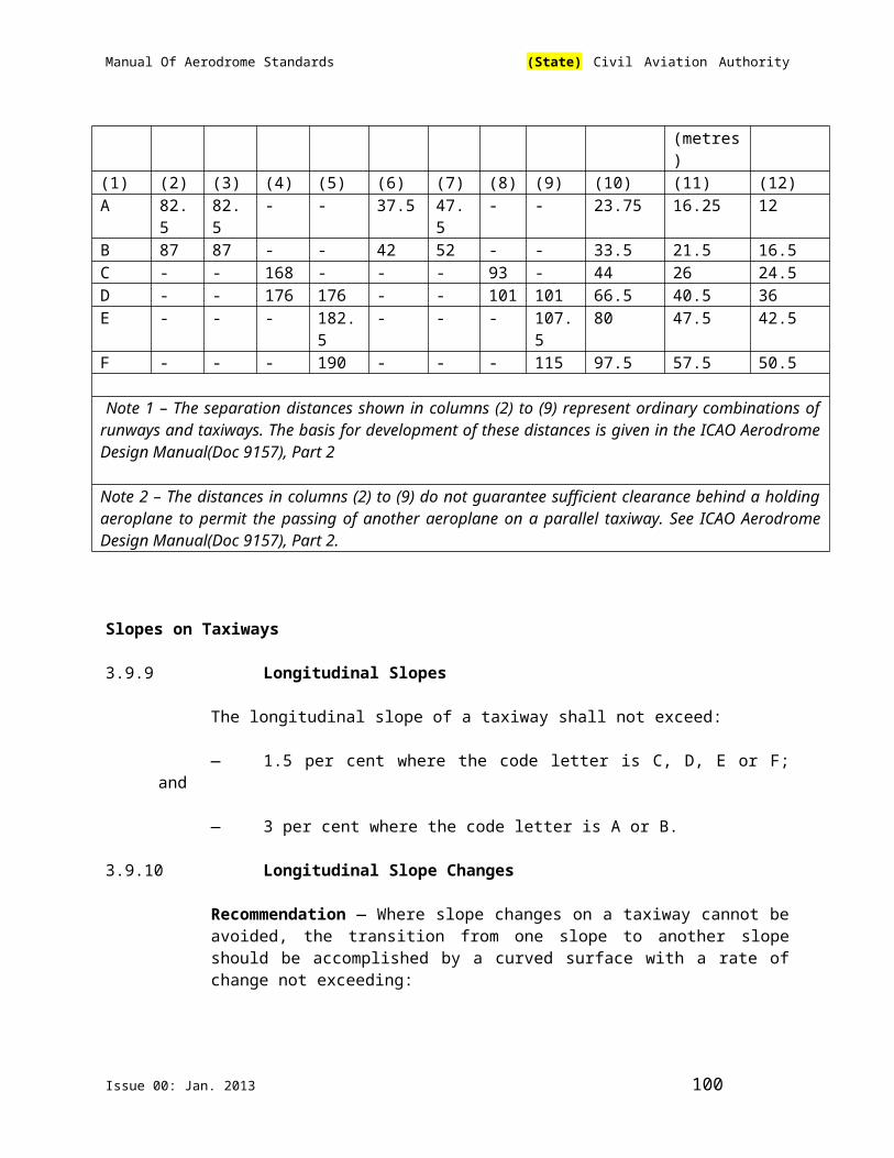
Manual Of Aerodrome Standards (State) Civil Aviation Authority
Note — See section 5.2.8.7 of this Part regarding the manner of connecting runway and taxiway centre line markings.
Colour and Conspicuity
5.2.1.4 Runway Markings shall be White.
Note 1 — It has been found that, on runway surfaces of light colour, the conspicuity of white markings can be improved by outlining them
in black.
Note 2 — It is preferable that the risk of uneven friction characteristics on markings be reduced in so far as practicable by the use of a suitable kind of paint.
Note 3 — Markings may consist of solid areas or a series of longitudinal stripes providing an effect equivalent to the solid areas.
5.2.1.5 Taxiway markings, runway turn pads and aircraft stand markings shall be yellow.
5.2.1.6 Apron safety lines shall be of a conspicuous colour which shall contrast with that used for aircraft stand markings.
5.2.1.7 Recommendation — At aerodromes where operations take place at night, pavement markings should be made with reflective materials designed to enhance the visibility of the markings.
Note — Guidance on reflective materials is given in the ICAO Aerodrome Design Manual (Doc 9157), Part 4.
Unpaved Taxiways
5.2.1.8 Recommendation — An unpaved taxiway should be provided, so far as practicable, with the markings prescribed for paved taxiways.
5.2.2 Runway Designation Marking
Application
5.2.2.1 A runway designation marking shall be provided at the thresholds of a paved runway.
5.2.2.2 Recommendation — A runway designation marking should be provided, so far as practicable, at the thresholds of an unpaved runway.
Location
5.2.2.3 A runway designation marking shall be located at a threshold as shown in ICAO Annex 14, Vol. I, Figure 5-2 as appropriate.
Issue 00: Jan. 2013 100
Manual Of Aerodrome Standards (State) Civil Aviation Authority
Note — If the runway threshold is displaced from the extremity of the runway, a sign showing the designation of the runway may be provided for aeroplanes taking off.
Characteristics
5.2.2.4 A runway designation marking shall consist of a two-digit number and on parallel runways shall be supplemented with a letter. On a single runway, dual parallel runways and triple parallel runways the two-digit number shall be the whole number nearest the one-tenth of the magnetic north when viewed from the direction of approach. On four or more parallel runways, one set of adjacent runways shall be numbered to the nearest one-tenth magnetic azimuth and the other set of adjacent runways numbered to the next nearest one-tenth of the magnetic azimuth. When the above rule would give a single digit number, it shall be preceded by a zero.
5.2.2.5 In the case of parallel runways, each runway designation number shall be supplemented by a letter as follows, in the order shown from left to right when viewed from the direction of approach:
— for two parallel runways: “L” “R”;
— for three parallel runways: “L” “C” “R”;
— for four parallel runways: “L” “R” “L” “R”;
— for five parallel runways: “L” “C” “R” “L” “R” or “L” “R” “L” “C”“R”; and
— for six parallel runways: “L” “C” “R” “L” “C” “R”.
5.2.2.6 The numbers and letters shall be in the form and proportion shown in ICAO Annex 14 Vol. I, Figure 5-3. The dimensions shall be not less than those shown in ICAO Annex 14 Vol. I, Figure 5-3, but where the numbers are incorporated in the threshold marking, larger dimensions shall be used in order to fill adequately the gap between the stripes of the threshold marking.
5.2.3 Runway Centre Line Marking
Application
5.2.3.1 A runway centre line marking shall be provided on a paved runway.
Location
5.2.3.2 A runway centre line marking shall be located along the centre line of the runway between the runway designation markings as shown in ICAO Annex 14 Vol. I, Figure 5-2, except when interrupted in compliance with section 9.2.2.1.1 of this Part
Issue 00: Jan. 2013 101

Manual Of Aerodrome Standards (State) Civil Aviation Authority
Characteristics
5.2.3.3 A runway centre line marking shall consist of a line of uniformly spaced stripes and gaps. The length of a stripe plus a gap shall be not less than 50 m or more than 75 m. The length of each stripe shall be at least equal to the length of the gap or 30 m, whichever is greater.
5.2.3.4 The width of the stripes shall be not less than:
— 0.90 m on precision approach category II and III runways;
— 0.45 m on non-precision approach runways where the code number is 3 or 4, and precision approach category I runways; and
— 0.30 m on non-precision approach runways where the code number is 1 or 2, and on non-instrument runways.
5.2.4 Threshold Marking
Application
5.2.4.1 A threshold marking shall be provided at the threshold of a paved instrument runway, and of a paved non- instrument runway where the code number is 3 or 4 and the runway is intended for use by international commercial air transport.
5.2.4.2 Recommendation — A threshold marking should be provided at the threshold of a paved non-instrument runway where the code number is 3 or 4 and the runway is intended for use by other than international commercial air transport.
5.2.4.3 Recommendation — A threshold marking should be provided, so far as practicable, at the thresholds of an unpaved runway.
Note — The ICAO Aerodrome Design Manual (Doc 9157), Part 4, shows a form of marking which has been found satisfactory for the marking of downward slopes immediately before the threshold.
Location
5.2.4.4 The stripes of the threshold marking shall commence 6 m from the threshold.
Characteristics
5.2.4.5 A runway threshold marking shall consist of a pattern of longitudinal stripes of uniform dimensions disposed symmetrically about the centre line of a runway as shown in ICAO Annex 14 Vol. I, Figure 5-2 (A) and (B) for a runway width of 45m. The number of stripes shall be in accordance with the runway width as follows:
Issue 00: Jan. 2013 102
Manual Of Aerodrome Standards (State) Civil Aviation Authority
Runway width Number of stripes18m 4
23m 6
30m 8
45m 12
60m 16
except that on non-precision approach and non-instrument runways 45m or greater in width, they may be as shown in ICAO Annex 14, Vol. I, Figure 5-2 (C).
The stripes shall extend laterally to within 3m of the edge of a runway or to a distance of 27m on either side of a runway centre line, whichever results in the smaller lateral distance. Where a runway designation marking is placed within a threshold marking there shall be a minimum of three stripes on each side of the centre line of the runway. Where a runway designation marking is placed above a threshold marking, the stripes shall be continued across the runway. The stripes shall be at least 30m long and approximately 1.80 m wide with spacing’s of approximately 1.80m between them except that, where the stripes are continued across a runway, a double spacing shall be used to separate the two stripes nearest the centre line of the runway, and in the case where the designation marking is included within the threshold marking this spacing shall be 22.5 m.
Transverse Stripe
5.2.4.7 Where a threshold is displaced from the extremity of a runway or where the extremity of a runway is not square with the runway centre line, a transverse stripe as shown in ICAO Annex 14, Vol. I, Figure 5-4 (B) shall be added to the threshold marking.
5.2.4.8 A transverse stripe shall be not less than 1.80 m wide.
Arrows
5.2.54.9 Where a runway threshold is permanently displaced, arrows conforming to ICAO Annex 14 Vol. I, Figure 5-4 (B) shall be provided on the portion of the runway before the displaced threshold.
5.2.4.10 When a runway threshold is temporarily displaced from the normal position, it shall be marked as shown in ICAO Annex 14, Vol. I, Figure 5-4 (A) or 5-4 (B) and all markings prior to the displaced threshold shall be obscured except the runway centre line marking, which shall be converted to arrows.
Note 1 — In the case where a threshold is temporarily displaced for only a short period of time, it has been found satisfactory to use markers in the form and
Issue 00: Jan. 2013 103
Manual Of Aerodrome Standards (State) Civil Aviation Authority
colour of a displaced threshold marking rather than attempting to paint this marking on the runway.
Note 2 — When the runway before a displaced threshold is unfit for the surface movement of aircraft, closed markings, as described in section 7.1.4 of this Manual, are required to be provided.
5.2.5 Aiming Point Marking
Application
5.2.5.1 Left Blank Intentionally
5.2.5.2 An aiming point marking shall be provided at each approach end of a paved instrument runway where the code number is 2, 3 or 4.
5.2.5.3 Recommendation — An aiming point marking should be provided at each approach end of:
(a) a paved non-instrument runway where the code number is 3 or 4,
(b) a paved instrument runway where the code number is 1, when additional conspicuity of the aiming point is desirable.
Location
5.2.5.4 The aiming point marking shall commence no closer to the threshold than the distance indicated in the appropriate column of Table 5-1 of this Manual, except that, on a runway equipped with a visual approach slope indicator system, the beginning of the marking shall be coincident with the visual approach slope origin.
5.2.5.5 An aiming point marking shall consist of two conspicuous stripes. The dimensions of the stripes and the lateral spacing between their inner sides shall be in accordance with the provisions of the appropriate column of Table 5-1 of this Manual. Where a touchdown zone marking is provided, the lateral spacing between the markings shall be the same as that of the touch-down zone marking.
Table 5-1 – Location and dimensions of aiming point marking
Landing distance availableLocation andDimension
Less than800 m
800 m up to butnot including1 200 m
1 200 m up to butnot including2 400 m
2 400 m andabove
(1) (2) (3) (4) (5)Distance fromthreshold tobeginning of
150 m 250 m 300 m 400 m
Issue 00: Jan. 2013 104

Manual Of Aerodrome Standards (State) Civil Aviation Authority
markingLength of stripea 30-45 m 30-45 m 45-60 m 45-60 mWidth of stripe 4 m 6 m 6-10 mb 6-10mb
Lateral spacingbetween innersides of stripes
6 mc 9 mc 18-22.5 m 18-22.5 m
a. The greater dimensions of the specified ranges are intended to be used where increased conspicuity is required.
b. The lateral spacing may be varied within these limits to minimize the contamination of the marking by rubber deposits.
c. These figures were deduced by reference to the outer main gear wheel span which is element 2 of the aerodrome reference code at Chapter 2, Table 2-1
5.2.6 Touchdown Zone Marking
Application
5.2.6.1 A touchdown zone marking shall be provided in the touchdown zone of a paved precision approach runway where the code number is 2, 3 or 4.
5.2.6.2 Recommendation — A touchdown zone marking should be provided in the touchdown zone of a paved non-precision approach or non-instrument runway where the code number is 3 or 4 and additional conspicuity of the touchdown zone is desirable.
Location and Characteristics
5.2.6.3 A touchdown zone marking shall consist of pairs of rectangular markings symmetrically disposed about the runway centre line with the number of such pairs related to the landing distance available and, where the marking is to be displayed at both the approach directions of a runway, the distance between the thresholds, as follows:
Landing distance available or the distance between the threshold
Pair(s) of markings
Less than 900 m 1
900m up to but not including 1 200 m 2
1 200m up to but not including 1 500 m 3
1 500m up to but not including 2 400 m 4
2 400m or more 6
Issue 00: Jan. 2013 105

Manual Of Aerodrome Standards (State) Civil Aviation Authority
5.2.6.4 A touchdown zone marking shall conform to either of the two patterns shown in ICAO Annex 14 Vol. I, Figure 5-5. For the pattern shown in ICAO Annex 14 Vol. I, Figure 5-5 (A), the markings shall be not less than 22.5 m long and 3 m wide. For the pattern shown in ICAO Annex 14 Vol. I, Figure 5-5(B), each stripe of each marking shall be not less than 22.5 m long and 1.8 m wide with a spacing of 1.5 m between adjacent stripes. The lateral spacing between the inner sides of the rectangles shall be equal to that of the aiming point marking where provided. Where an aiming point marking is not provided, the lateral spacing between the inner sides of the rectangles shall correspond to the lateral spacing specified for the aiming point marking in Table 5-1 of this Manual (columns 2, 3, 4 or 5, as appropriate). The pairs of markings shall be provided at longitudinal spacing of 150 m beginning from the threshold except that pairs of touchdown zone markings coincident with or located within 50m of an aiming point marking shall be deleted from the pattern.
5.2.6.5 Recommendation — On a non-precision approach runway where the code number is 2, an additional pair of touchdown zone marking stripes should be provided 150 m beyond the beginning of the aiming point marking.
5.2.7 Runway Side Stripe Marking
Application
5.2.7.1 A runway side stripe marking shall be provided between the thresholds of a paved runway where there is a lack of contrast between the runway edges and the shoulders or the surrounding terrain.
5.2.7.2 A runway side stripe marking shall be provided on a precision approach runway irrespective of the contrast between the runway edges and the shoulders or the surrounding terrain.
Location
5.2.7.3 A runway side stripe marking shall consist of two stripes, one placed along each edge of the runway with the outer edge of each stripe approximately on the edge of the runway, except that, where the runway is greater than 60 m in width, the stripes should be located 30 m from the runway centre line.
5.2.7.4. Recommendation - Where runway turn pad is provided, the runway stripe marking should be continued betweenthe runway and the runway turn pad.
Characteristics
5.2.7.5 Recommendation - A runway side stripe should have an overall width of at least 0.9 m on runways 30 m or more in width and at least 0.45 m on narrower runways.
5.2.8 Taxiway Centre Line Marking
Application
Issue 00: Jan. 2013 106

Manual Of Aerodrome Standards (State) Civil Aviation Authority
5.2.8.1 Taxiway centre line marking shall be provided on a paved taxiway and apron where the code number is 3 or 4 in such a way as to provide continuous guidance between the runway centre line and aircraft stands.
5.2.8.2 Recommendation — Taxiway centre line marking should be provided on a paved taxiway and apron where the code number is 1 or 2 in such a way as to provide continuous guidance between the runway centre line and aircraft stands.
5.2.8.3 Taxiway centre line marking shall be provided on a paved runway when the runway is part of a standard taxi-route and:
(a) there is no runway centre line marking; or
(b) where the taxiway centre line is not coincident with the runway centreline.
Location
5.2.8.4 Recommendation.— Where it is necessary to denote the proximity of a runway-holding position, enhanced taxiway centre line marking should be provided.
Note.— The provision of enhanced taxiway centre line marking may form part of runway incursion prevention measures.
5.2.8.5 Recommendation — Where provided, enhanced taxiway centre line marking should be installed at all taxiway/runway intersections at that aerodrome
5.2.8.6 Recommendation — On a straight section of a taxiway, the taxiway centre line marking should be located along the taxiway centre line. On a taxiway curve the marking should continue from the straight portion of the taxiway at a constant distance from the outside edge of the curve.
Note — See section 3.9.6 and ICAO Annex 14, Vol. I, Figure 3-2.
5.2.8.7 Recommendation — At an intersection of a taxiway with a runway where the taxiway serves as an exit from the runway, the taxiway centre line marking should be curved into the runway centre line marking as shown in ICAO Annex 14, Vol. I, Figures 5-6 and 5-26. The taxiway centre line marking should be extended parallel to the runway centre line marking for a distance of at least 60 m beyond the point of tangency where the code number is 3 or 4, and for a distance of at least 30 m where the code number is 1 or 2.
5.2.8.8 Recommendation — Where taxiway centre line marking is provided on a runway in accordance with section 5.2.8.3, the marking should be located on the centre line of the designated taxiway.
5.2.8.9 Where provided, an enhanced taxiway centre line marking shall extend from the runway-holding position pattern A (as defined in Figure 5-6, Taxiway markings) to a distance of up to 45 m (a minimum of three (3) dashed lines) in the direction of
Issue 00: Jan. 2013 107

Manual Of Aerodrome Standards (State) Civil Aviation Authority
travel away from the runway or to the next runway-holding position, if within 45 m distance.
Characteristics
5.2.8.10 A taxiway centre line marking shall be at least 15cm in width and continuous in length except where it intersects with a runway-holding position marking or an intermediate holding position marking as shown in ICAO Annex 14, Vol. I, Figure 5-6.
5.2.8.11 Enhanced taxiway centre line marking shall be as shown in Figure 5-7.
5.2.9 Runway Turn Pad Marking
Application
5.2.9.1 Where a runway turn pad is provided, a runway turn pad marking shall be provided for continuous guidance to enable an aeroplane to complete a 180-degree turn and align with the runway centre line.
Location
5.2.9.2 Recommendation.— The runway turn pad marking should be curved from the runway centre line into the turn pad. The radius of the curve should be compatible with the manoeuvring capability and normal taxiing speeds of the aeroplanes for which the runway turn pad is intended. The intersection angle of the runway turn pad marking with the runway centre line should not be greater than 30 degrees.
5.2.9.3 Recommendation.— The runway turn pad marking should be extended parallel to the runway centre line marking for a distance of at least 60 m beyond the point of tangency where the code number is 3 or 4, and for a distance of at least 30 m where the code number is 1 or 2.
5.2.9.4 Recommendation.— A runway turn pad marking should guide the aeroplane in such a way as to allow a straight portion of taxiing before the point where a 180-degree turn is to be made. The straight portion of the runway turn pad marking should be parallel to the outer edge of the runway turn pad.
5.2.9.5 Recommendation.— The design of the curve allowing the aeroplane to negotiate a 180-degree turn should be based on a nose wheel steering angle not exceeding 45 degrees.
5.2.9.6 Recommendation.— The design of the turn pad marking should be such that, when the cockpit of the aeroplane remains over the runway turn pad marking, the clearance distance between any wheel of the aeroplane landing gear and the edge of the runway turn pad should be not less than those specified in section 3.3.6
Issue 00: Jan. 2013 108
Manual Of Aerodrome Standards (State) Civil Aviation Authority
Note.— For ease of manoeuvring, consideration may be given to providing a larger wheel-to-edge clearance for codes E and F aeroplanes. See section 3.3.7.
Characteristics
5.2.9.7 A runway turn pad marking shall be at least 15 cm in width and continuous in length.
5.2.10 Runway-Holding Position Marking
Application and Location
5.2.10.1 A runway-holding position marking shall be displayed along a runway-holding position.
Note — See section 5.4.2 concerning the provision of signs at runway-holding positions.
Characteristics
5.2.10.2 At an intersection of a taxiway and a non-instrument, non-precision approach or take-off runway, the runway-holding position marking shall be as shown in ICAO Annex 14, Vol. I, Figure 5-6, pattern A.
5.2.10.3 Where a single runway-holding position is provided at an intersection of a taxiway and a precision approach category I, II or III runway, the runway-holding position marking shall be as shown in ICAO Annex 14, Vol. I, Figure 5-6, pattern A. Where two or three runway-holding positions are provided at such an intersection, the runway-holding position marking closer (closest) to the runway shall be as shown in ICAO Annex 14, Vol. I, Figure 5-6, pattern A and the markings farther from the runway shall be as shown in ICAO Annex 14, Vol. I, Figure 5-6, pattern B.
5.2.10.4 The runway-holding position marking displayed at a runway-holding position established in accordance with section 5.12.3 of this Part shall be as shown in ICAO Annex 14 Vol. I, Figure 5-6, pattern A.
5.2.10.5 Recommendation — Where increased conspicuity of the runway-holding position is required, the runway-holding position marking should be as shown in ICAO Annex 14, Vol. I, Figure 5-8, pattern A or pattern B, as appropriate.
5.2.10.6 Recommendation — Where a pattern B runway-holding position marking is located on an area where it would exceed 60 m in length, the term “CAT II” or “CAT III” as appropriate should be marked on the surface at the ends of the runway-holding position marking and at equal intervals of 45 m maximum between successive marks. The letters should be not less than 1.8 m high and should be placed not more than 0.9 m beyond the holding position marking.
5.2.10.7 The runway-holding position marking displayed at a runway/runway intersection shall be perpendicular to the centre line of the runway forming part of the
Issue 00: Jan. 2013 109

Manual Of Aerodrome Standards (State) Civil Aviation Authority
standard taxi-route. The pattern of the marking shall be as shown in ICAO Annex 14, Vol. I, Figure 5-8, pattern A.
5.2.11 Intermediate Holding Position Marking
Application and Location
5.2.11.1 Recommendation — An intermediate holding position marking should be displayed along an intermediate holding position.
5.2.11.2 Not applicable
5.2.11.3 Where an intermediate holding position marking is displayed at an intersection of two paved taxiways, it shall be located across the taxiway at sufficient distance from the near edge of the intersecting taxiway to ensure safe clearance between taxiing aircraft. It shall be coincident with a stop bar or intermediate holding position lights, where provided.
5.2.11.4 Not applicable.
Characteristics
5.2.11.5 An intermediate holding position marking shall consist of a single broken line as shown in ICAO Annex 14. Vol. I, Figure 5-6.
5.2.12 VOR Aerodrome Check-Point Marking
Application
5.2.12.1 When a VOR aerodrome check-point is established, it shall be indicated by a VOR aerodrome check-point marking and sign.
Note — See section 5.4.4 for VOR aerodrome check-point sign.
5.2.12.2 Site selection
Note — Guidance on the selection of sites for VOR aerodrome check-points is given in ICAO Annex 10, Vol. 1, Attachment E.
Location
5.2.12.3 A VOR aerodrome check-point marking shall be centred on the spot at which an aircraft is to be parked to receive the correct VOR signal.
Characteristics
5.2.12.4 A VOR aerodrome check-point marking shall consist of a circle 6 m in diameter and have a line width of 15 cm (See ICAO Annex 14. Vol. I, Figure 5-9 (A)).
Issue 00: Jan. 2013 110

Manual Of Aerodrome Standards (State) Civil Aviation Authority
5.2.12.5 Recommendation — When it is preferable for an aircraft to be aligned in a specific direction, a line should be provided that passes through the centre of the circle on the desired azimuth. The line should extend 6 m outside the circle in the desired direction of heading and terminate in an arrowhead. The width of the line should be 15 cm (see ICAO Annex 14. Vol. I, Figure 5-9 (B)).
5.2.12.6 Recommendation — A VOR aerodrome check-point marking should preferably be white in colour but should differ from the colour used for the taxiway markings.
Note — To provide contrast, markings may be bordered with black.
5.2.13 Aircraft Stand Markings
Note — Guidance on the layout of aircraft stand markings is contained in the ICAO Aerodrome Design Manual(Doc 9157), Part 4.
Application
5.2.13.1 Recommendation — Aircraft stand markings should be provided for designated parking positions on a paved apron.
Location
5.2.13.2 Recommendation — Aircraft stand markings on a paved apron should be located so as to provide the clearances specified in section 3.13.6, when the nose wheel follows the stand marking.
Characteristics
5.2.13.3 Recommendation — Aircraft stand markings should include such elements as stand identification, lead-in line, turn bar, turning line, alignment bar, stop line and lead-out line, as are required by the parking configuration and to complement other parking aids.
5.2.13.4 Recommendation — An aircraft stand identification (letter and/or number) should be included in the lead-in line a short distance after the beginning of the lead-in line. The height of the identification should be adequate to be readable from the cockpit of aircraft using the stand.
5.2.13.5 Recommendation — Where two sets of aircraft stand markings are superimposed on each other in order to permit more flexible use of the apron and it is difficult to identify which stand marking should be followed, or safety would be impaired if the wrong marking was followed, then identification of the aircraft for which each set of markings is intended should be added to the stand identification.
Note — Example: 2A-B747, 2B-F28.
5.2.13.6 Recommendation — Lead-in, turning and lead-out lines should normally be continuous in length and have a width of not less than 15 cm. Where one or more
Issue 00: Jan. 2013 111

Manual Of Aerodrome Standards (State) Civil Aviation Authority
sets of stand markings are superimposed on a stand marking, the lines should be continuous for the most demanding aircraft and broken for other aircraft.
5.2.13.7 Recommendation — The curved portions of lead-in, turning and lead-out lines should have radii appropriate to the most demanding aircraft type for which the markings are intended.
5.2.13.8 Recommendation — Where it is intended that an aircraft proceed in one direction only, arrows pointing in the direction to be followed should be added as part of the lead-in and lead-out lines.
5.2.13.9 Recommendation — A turn bar should be located at right angles to the lead-in line, abeam the left pilot position at the point of initiation of any intended turn. It should have a length and width of not less than 6 m and 15 cm, respectively, and include an arrowhead to indicate the direction of turn.
Note — The distances to be maintained between the turn bar and the lead-in line may vary according to different aircraft types, taking into account the pilot’s field of view.
5.2.13.10 Recommendation — If more than one turn bar and/or stop line is required, they should be coded.
5.2.13.11 Recommendation — An alignment bar should be placed so as to be coincident with the extended centre line of the aircraft in the specified parking position and visible to the pilot during the final part of the parking manoeuvre. It should have a width of not less than 15 cm.
5.2.13.12 Recommendation — A stop line should be located at right angles to the alignment bar, abeam the left pilot position at the intended point of stop. It should have a length and width of not less than 6 m and 15 cm, respectively.
Note — The distances to be maintained between the stop line and the lead-in line may vary according to different aircraft types, taking into account the pilot’s field of view.
5.2.14 Apron Safety Lines
Note — Guidance on apron safety lines is contained in the ICAO Aerodrome Design Manual (Doc 9157), Part 4.
Application
5.2.14.1 Recommendation — Apron safety lines should be provided on a paved apron as required by the parking configurations and ground facilities.
Location
Issue 00: Jan. 2013 112

Manual Of Aerodrome Standards (State) Civil Aviation Authority
5.2.14.2 Apron safety lines shall be located so as to define the areas intended for use by ground vehicles and other aircraft servicing equipment, etc., to provide safe separation from aircraft.
Characteristics
5.2.14.3 Recommendation — Apron safety lines should include such elements as wing tip clearance lines and service road boundary lines as required by the parking configurations and ground facilities.
5.2.14.4 Recommendation — An apron safety line should be continuous in length and at least 10 cm in width.
5.2.15 Road-Holding Position Marking
Application
5.2.15.1 A road-holding position marking shall be provided at all road entrances to a runway.
Location
5.2.15.2 The road-holding position marking shall be located across the road at the holding position.
Characteristics
5.2.15.3 The road-holding position marking shall be in accordance with the local road traffic regulations.
5.2.16 Mandatory Instruction Marking
Note — Guidance on mandatory instruction marking is given in the ICAO Aerodrome Design Manual(Doc 9157), Part 4.
Application
5.2.16.1 Where it is impracticable to install a mandatory instruction sign in accordance with section 5.4.2.1, a mandatory instruction marking shall be provided on the surface of the pavement.
5.2.16.2 Recommendation — Where operationally required, such as on taxiways exceeding 60 m in width, a mandatory instruction sign should be supplemented by a mandatory instruction marking.
Location
5.2.16.3 The mandatory instruction marking shall be located on the left-hand side of the taxiway centre line marking and on the holding side of the runway-holding position marking as shown in ICAO Annex 14, Vol. I, Figure 5-10(A). The
Issue 00: Jan. 2013 113

Manual Of Aerodrome Standards (State) Civil Aviation Authority
distance between the nearest edge of the marking and the runway-holding position marking or the taxiway centre line marking shall be not less than 1 m.
5.2.16.4 The mandatory instruction marking on taxiways where the code letter is E or F shall be located on both sides of the taxiway centre line marking and on the holding side of the runway-holding position marking as shown in Figure 5-10 (B). The distance between the nearest edge of the marking and the runway-holding position marking or the taxiway centre line marking shall be not less than 1 m.
5.2.16.5 Recommendation — Except where operationally required, a mandatory instruction marking should not be located on a runway.
Characteristics
5.2.16.6 A mandatory instruction marking shall consist of an inscription in white on a red background. Except for a NO ENTRY marking, the inscription shall provide information identical to that of the associated mandatory instruction sign.
5.2.16.7 A ‘NO ENTRY’ marking shall consist of an inscription in white reading ‘NO ENTRY’ on a red background.
5.2.16.8 Where there is insufficient contrast between the marking and the pavement surface, the mandatory instruction marking shall include an appropriate border, preferably white or black.
5.2.16.9 Recommendation—The character height should be 4 m. The inscriptions should be in the form and proportions shown in ICAO Annex 14, Vol. I, Appendix 3.
5.2.16.10 Recommendation — The background should be rectangular and extend a minimum of 0.5 m laterally and vertically beyond the extremities of the inscription.
5.2.17 Information Marking
Note — Guidance on information marking is contained in the ICAO Aerodrome Design Manual(Doc 9157), Part 4.
Application
5.2.17.1 Where an information sign would normally be installed and is impractical to install, as determined by the appropriate authority, an information marking shall be displayed on the surface of the pavement.
5.2.17.2 Recommendation — Where operationally required an information sign should be supplemented by an information marking.
5.2.17.3 Recommendation.— An information (location/direction) marking should be displayed prior to and following complex taxiway intersections and where operational experience has indicated the addition of a taxiway location marking could assist flight crew ground navigation.
Issue 00: Jan. 2013 114

Manual Of Aerodrome Standards (State) Civil Aviation Authority
5.2.17.4 Recommendation.— An information (location) marking should be displayed on the pavement surface at regular intervals along taxiways of great length.
Location
5.2.17.5 Recommendation — The information marking should be displayed across the surface of the taxiway or apron where necessary and positioned so as to be legible from the cockpit of an approaching aircraft.
Characteristics
5.2.17.6 An information marking shall consist of:
(a) an inscription in yellow upon a black background, when it replaces or supplements a location sign; and
(b) an inscription in black upon a yellow background, when it replaces or supplements a direction or destination sign.
5.2.17.7 Where there is insufficient contrast between the marking background and the pavement surface, the marking shall include:
(a) a black border where the inscriptions are in black and
(b) a yellow border where the inscriptions are in yellow.
5.2.17.8 Recommendation — The character height should be 4 m. The inscriptions should be in the form and proportions shown in ICAO Annex 14, Vol. I, Appendix 3.
5.3 Lights
5.3.1 General
Lights which may Endanger the Safety of Aircraft
5.3.1.1 A non-aeronautical ground light near an aerodrome which might endanger the safety of aircraft shall be extinguished, screened or otherwise modified so as to eliminate the source of danger.
Laser Emissions which may Endanger the Safety of Aircraft
5.3.1.2 Recommendation — To protect the safety of aircraft against the hazardous effects of laser emitters, the following protected zones should be established around aerodromes— a laser-beam free flight zone (LFFZ),
— a laser-beam critical flights zone (LCFZ), and
Issue 00: Jan. 2013 115

Manual Of Aerodrome Standards (State) Civil Aviation Authority
— a laser-beam sensitive flight zone(LSFZ).
Note 1 — ICAO Annex 14 Vol. I, Figures 5-11, 5-12 and 5-13 may be used to determine the exposure levels and distances that adequately protect flights operations.
Note 2 – The restrictions on the use of laser beams in the three protected flight zones, LFFZ, LCFZ and LSFZ, refer to visible laser beams only. Laser emitters operated by the authorities in a manner compatible with flight safety are excluded. In all navigable air space, the irradiance level of any laser beam, visible or invisible, is expected to be less than or equal to the maximum permissible exposure (MPE) unless such emission has been notified to the authority and permission obtained.
Note 3 – The protected flight zones are established in order to mitigate the risks of operating laser emitters in the vicinity of aerodromes.
Note 4 – Further guidance on how to protect flight operations from the hazardous effects of laser emitters is contained in the ICAO Manual on Laser Emitters and Flights Safety (ICAO Doc 9815).
Note 5 – See also ICAO Annex 11 – Air Traffic Services, Chapter 2.
Lights which may Cause Confusion
5.3.1.3 Recommendation — A non-aeronautical ground light which, by reason of its intensity, configuration or colour, might prevent, or cause confusion in, the clear interpretation of aeronautical ground lights should be extinguished, screened or otherwise modified so as to eliminate such a possibility. In particular, attention should be directed to a non-aeronautical ground light visible from the air within the areas described hereunder:
(a) Instrument runway — code number 4: within the areas before the threshold and beyond the end of the runway extending at least 4500 m in length from the threshold and runway end and 750 m either side of the extended runway centre line in width.
(b) Instrument runway — code number 2 or 3: as in a), except that the length should be at least 3 000 m.
(c) Instrument runway — code number 1; and non-instrument runway: within the approach area.
Aeronautical Ground Lights which may Cause Confusion to Mariners
Note — In the case of aeronautical ground lights near navigable waters, consideration needs to be given to ensure that the lights do not cause confusion to mariners.
Light fixtures and supporting structures
Issue 00: Jan. 2013 116

Manual Of Aerodrome Standards (State) Civil Aviation Authority
Note — See section 9.2.9 for information regarding siting and construction of equipment and installations on operational areas, and the ICAO Aerodrome Design Manual(Doc 9157), Part 6 (in preparation) for guidance on frangibility of light fixtures and supporting structures.
Elevated Approach Lights
5.3.1.4 Elevated approach lights and their supporting structures shall be frangible except that, in that portion of the approach lighting system beyond 300 m from the threshold:
(a) where the height of a supporting structure exceeds 12 m, the frangibility requirement shall apply to the top 12 m only; and
(b) where a supporting structure is surrounded by non-frangible objects, only that part of the structure that extends above the surrounding objects shall be frangible.
5.3.1.5 Left Blank Intentionally
5.3.1.6 When an approach light fixture or supporting structure is not in itself sufficiently conspicuous, it shall be suitably marked.
Elevated Lights
5.3.1.7 Elevated runway, stopway and taxiway lights shall be frangible. Their height shall be sufficiently low to preserve clearance for propellers and for the engine pods of jet aircraft.
Surface Lights
5.3.1.8 Light fixtures inset in the surface of runways, stopways, taxiways and aprons shall be so designed and fitted as to withstand being run over by the wheels of an aircraft without damage either to the aircraft or to the lights themselves.
5.3.1.9 Recommendation — The temperature produced by conduction or radiation at the interface between an installed inset light and an aircraft tyre should not exceed 160°C during a 10-minute period of exposure.
Note — Guidance on measuring the temperature of inset lights is given in the ICAO Aerodrome Design Manual(Doc 9157), Part 4.
Light Intensity and Control
Note — In dusk or poor visibility conditions by day, lighting can be more effective than marking. For lights to be effective in such conditions or in poor visibility by night, they must be of adequate intensity. To obtain the required intensity, it will usually be necessary to make the light directional, in which case the arcs over which the light shows will have to be adequate and so orientated as to meet the
Issue 00: Jan. 2013 117

Manual Of Aerodrome Standards (State) Civil Aviation Authority
operational requirements. The runway lighting system will have to be considered as a whole, to ensure that the relative light intensities are suitably matched to the same end. (See Attachment A, Section 15, and the ICAO Aerodrome Design Manual(Doc 9157), Part 4.)
5.3.1.10 The intensity of runway lighting shall be adequate for the minimum conditions of visibility and ambient light in which use of the runway is intended, and
compatible with that of the nearest section of the approach lighting system when provided.
Note — While the lights of an approach lighting system may be of higher intensity than the runway lighting, it is good practice to avoid abrupt changes in intensity as these could give a pilot a false impression that the visibility is changing during approach.
5.3.1.11 Where a high-intensity lighting system is provided, a suitable intensity control shall be incorporated to allow for adjustment of the light intensity to meet the prevailing conditions. Separate intensity controls or other suitable methods shall be provided to ensure that the following systems, when installed, can be operated at compatible intensities:
— approach lighting system;— runway edge lights;— runway threshold lights;— runway end lights;— runway centre line lights;— runway touchdown zone lights; and— taxiway centre line lights.
5.3.1.12 On the perimeter of and within the ellipse defining the main beam in ICAO Annex 14, Vol. I, Appendix 2, Figures A2-1 to A2-10, the maximum light intensity value shall not be greater than three times the minimum light intensity value measured in accordance with ICAO Annex 14, Vol. I, Appendix 2, collective notes for Figures A2-1 to A2-11, Note 2.
5.3.1.13 On the perimeter of and within the rectangle defining the main beam in ICAO Annex 14 Vol. I, Appendix 2, Figures A2-12 to A2-20, the maximum light intensity value shall not be greater than three times the minimum light intensity value measured in accordance with ICAO Annex 14, Vol. I, Appendix 2, collective notes for Figures A2-12 to A2-21, Note 2.
5.3.2 Emergency Lighting
Application
5.3.2.1 Recommendation — At an aerodrome provided with runway lighting and without a secondary power supply, sufficient emergency lights should be conveniently available for installation on at least the primary runway in the event of failure of the normal lighting system.
Issue 00: Jan. 2013 118

Manual Of Aerodrome Standards (State) Civil Aviation Authority
Note — Emergency lighting may also be useful to mark obstacles or delineate taxiways and apron areas.
Location
5.3.2.2 Recommendation — When installed on a runway the emergency lights should, as a minimum, conform to the configuration required for a non-instrument runway.
Characteristics
5.3.2.3 Recommendation — The colour of the emergency lights should conform to the colour requirements for runway lighting, except that, where the provision of coloured lights at the threshold and the runway end is not practicable, all lights may be variable white or as close to variable white as practicable.
5.2.3.3 Aeronautical Beacons
Application
5.3.3.1 Where operationally necessary an aerodrome beacon or an identification beacon shall be provided at each aerodrome intended for use at night.
5.3.3.2 The operational requirement shall be determined having regard to the requirements of the air traffic using the aerodrome, the conspicuity of the aerodrome features in relation to its surroundings and the installation of other visual and non-visual aids useful in locating the aerodrome.
Aerodrome beacon
5.3.3.3 An aerodrome beacon shall be provided at an aerodrome intended for use at night if one or more of the following conditions exist:
(a) aircraft navigate predominantly by visual means;
(b) reduced visibilities are frequent; or
(c) it is difficult to locate the aerodrome from the air due to surrounding lights or terrain.
Location
5.3.3.4 The aerodrome beacon shall be located on or adjacent to the aerodrome in an area of low ambient back-ground lighting.
5.3.3.5 Recommendation — The location of the beacon should be such that the beacon is not shielded by objects in significant directions and does not dazzle a pilot approaching to land.
Characteristics
Issue 00: Jan. 2013 119

Manual Of Aerodrome Standards (State) Civil Aviation Authority
5.3.3.6 The aerodrome beacon shall show either coloured flashes alternating with white flashes, or white flashes only. The frequency of total flashes shall be from 20 to 30 per minute. Where used, the coloured flashes emitted by beacons at land aerodromes shall be green and coloured flashes emitted by beacons at water aerodromes shall be yellow. In the case of a combined water and land aerodrome, coloured flashes, if used, shall have the colour characteristics of whichever section of the aerodrome is designated as the principal facility.
5.3.3.7 The light from the beacon shall show at all angles of azimuth. The vertical light distribution shall extend upwards from an elevation of not more than 1° to an elevation determined by the Aerodrome Standards Department to be sufficient to provide guidance at the maximum elevation at which the beacon is intended to be used and the effective intensity of the flash shall be not less than 2 000 cd.
Note — At locations where a high ambient background lighting level cannot be avoided, the effective intensity of the flash may be required to be increased by a factor up to a value of 10.
Identification Beacon
Application
5.3.3.8 An identification beacon shall be provided at an aerodrome which is intended for use at night and cannot be easily identified from the air by other means.
Location
5.3.3.9 The identification beacon shall be located on the aerodrome in an area of low ambient background lighting.
5.3.3.10 Recommendation — The location of the beacon should be such that the beacon is not shielded by objects in significant directions and does not dazzle a pilot approaching to land.
Characteristics
5.3.3.11 An identification beacon at a land aerodrome shall show at all angles of azimuth. The vertical light distribution shall extend upwards from an elevation of not more than 1° to an elevation determined by the Authority to be sufficient to provide guidance at the maximum elevation at which the beacon is intended to be used and the effective intensity of the flash shall be not less than 2 000 cd.
Note — At locations where a high ambient background lighting level cannot be avoided, the effective intensity of the flash may be required to be increased by a
factor up to a value of 10.
5.3.3.12 An identification beacon shall show flashing-green at a land aerodrome and flashing-yellow at a water aerodrome.
Issue 00: Jan. 2013 120

Manual Of Aerodrome Standards (State) Civil Aviation Authority
5.3.3.13 The identification characters shall be transmitted in the International Morse Code.
5.3.3.14 Recommendation — The speed of transmission should be between six and eight words per minute, the corresponding range of duration of the Morse dots being from 0.15 to 0.2 seconds per dot.
5.3.4 Approach Lighting Systems
Note — It is intended that existing lighting systems not conforming to the specifications in sections 5.3.4.21, 5.3.4.39, 5.3.9.10, 5.3.10.10, 5.3.10.11, 5.3.11.5, 5.3.12.8, 5.3.13.6 and 5.3.15.8 be replaced not later than 1 January 2005.
5.3.4.1 Application
A — Non-Instrument Runway
Recommendation — Where physically practicable, a simple approach lighting system as specified in sections 5.3.4.2 to 5.3.4.9 of this Manual should be provided to serve a non-instrument runway where the code number is 3 or 4 and intended for use at night, except when the runway is used only in conditions of good visibility, and sufficient guidance is provided by other visual aids.
Note — A simple approach lighting system can also provide visual guidance by day.
B — Non-Precision Approach Runway
Where physically practicable, a simple approach lighting system as specified in sections 5.3.4.2 to 5.3.4.9 of this Manual shall be provided to serve a non-precision approach runway, except when the runway is used only in conditions of good visibility or sufficient guidance is provided by other visual aids.
Note — It is advisable to give consideration to the installation of a precision approach category I lighting system or to the addition of a runway lead-in lighting system.
C — Precision Approach Runway Category I
Where physically practicable, a precision approach category I lighting system as .specified in sections 5.3.4.10 to 5.3.4.21 of this Manual shall be provided .to serve a precision approach runway category I.
D — Precision Approach Runway Categories II and III
Issue 00: Jan. 2013 121

Manual Of Aerodrome Standards (State) Civil Aviation Authority
A precision approach category II and III lighting system as specified in .sections 5.3.4.22 to 5.3.4.39 shall be provided to serve a . precision approach runway category II or III.
Simple Approach Lighting System
Location
5.3.4.2 A simple approach lighting system shall consist of a row of lights on the extended centre line of the runway extending, whenever possible, over a distance of not less than 420 m from the threshold with a row of lights forming a crossbar 18 m or 30 m in length at a distance of 300 m from the threshold.
5.3.4.3 The lights forming the crossbar shall be as nearly as practicable in a horizontal straight line at right angles to, and bisected by, the line of the centre line lights. The lights of the crossbar shall be spaced so as to produce a linear effect, except that, when a crossbar of 30 m is used, gaps may be left on each side of the centre line. These gaps shall be kept to a minimum to meet local requirements and each shall not exceed 6 m.
Note 1 — Spacing for the crossbar lights between 1 m and 4 m are in use. Gaps on each side of the centre line may improve directional guidance when approaches are made with a lateral error, and facilitate the movement of rescue and fire fighting vehicles.
Note 2 — See Attachment A, Section 11 for guidance on installation tolerances.
5.3.4.4 The lights forming the centre line shall be placed at longitudinal intervals of 60 m, except that, when it is desired to improve the guidance, an interval of 30 m may be used. The innermost light shall be located either 60 m or 30 m from the threshold, depending on the longitudinal interval selected for the centre line lights.
5.3.4.5 Recommendation — If it is not physically possible to provide a centre line extending for a distance of 420 m from the threshold, it should be extended to 300 m so as to include the crossbar. If this is not possible, the centre line lights should be extended as far as practicable, and each centre line light should then consist of a barrette at least 3 m in length. Subject to the approach system having a crossbar at 300 m from the threshold, an additional crossbar may be provided at 150 m from the threshold.
5.3.4.6 The system shall lie as nearly as practicable in the horizontal plane passing through the threshold, provided that:
(a) no object other than an ILS or MLS azimuth antenna shall protrude through the plane of the approach lights within a distance of 60 m from the centre line of the system; and
(b) no light other than a light located within the central part of a crossbar or a centre line barrette (not their extremities) shall be screened from an approaching aircraft.
Issue 00: Jan. 2013 122

Manual Of Aerodrome Standards (State) Civil Aviation Authority
Any ILS or MLS azimuth antenna protruding through the plane of the lights shall be treated as an obstacle and marked and lighted accordingly.
Characteristics
5.3.4.7 The lights of a simple approach lighting system shall be fixed lights and the colour of the lights shall be such as to ensure that the system is readily distinguishable from other aeronautical ground lights, and from extraneous lighting if present. Each centre line light shall consist of either:
(a) a single source; or
(b) a barrette at least 3 m in length.
Note 1 — When the barrette as in b) is composed of lights approximating to point sources, a spacing of 1.5 m between adjacent lights in the barrette has been found satisfactory.
Note 2 — It may be advisable to use barrettes 4 m in length if it is anticipated that the simple approach lighting system will be developed into a precision approach lighting system.
Note 3 — At locations where identification of the simple approach lighting system is difficult at night due to surrounding lights, sequence flashing lights installed in the outer portion of the system may resolve this problem.
5.3.4.8 Recommendation — Where provided for a non-instrument runway, the lights should show at all angles in azimuth necessary to a pilot on base leg and final approach. The intensity of the lights should be adequate for all conditions of visibility and ambient light for which the system has been provided.
5.3.4.9 Recommendation — Where provided for a non-precision approach runway, the lights should show at all angles in azimuth necessary to the pilot of an aircraft which on final approach does not deviate by an abnormal amount from the path defined by the non-visual aid. The lights should be designed to provide guidance during both day and night in the most adverse conditions of visibility and ambient light for which it is intended that the system should remain usable.
Precision Approach Category I Lighting System
Location
5.3.4.10 A precision approach category I lighting system shall consist of a row of lights on the extended centre line of the runway extending, wherever possible, over a distance of 900 m from the runway threshold with a row of lights forming a crossbar 30 m in length at a distance of 300 m from the runway threshold.
Issue 00: Jan. 2013 123

Manual Of Aerodrome Standards (State) Civil Aviation Authority
Note — The installation of an approach lighting system of less than 900 m in length may result in operational limitations on the use of the runway. See Attachment A, Section 11.
5.3.4.11 The lights forming the crossbar shall be as nearly as practicable in a horizontal straight line at right angles to, and bisected by, the line of the centre line lights. The lights of the crossbar shall be spaced so as to produce a linear effect, except that gaps may be left on each side of the centre line. These gaps shall be kept to a minimum to meet local requirements and each shall not exceed 6 m.
Note 1 — Spacing for the crossbar lights between 1 m and 4 m are in use. Gaps on each side of the centre line may improve directional guidance when approaches are made with a lateral error, and facilitate the movement of rescue and fire fighting vehicles.
Note 2 — See Attachment A, Section 11 for guidance on installation tolerances.
5.3.4.12 The lights forming the centre line shall be placed at longitudinal intervals of 30 m with the innermost light located 30 m from the threshold.
5.3.4.13 The system shall lie as nearly as practicable in the horizontal plane passing through the threshold, provided that:
(a) no object other than an ILS or MLS azimuth antenna shall protrude through the plane of the approach lights within a distance of 60 m from the centre line of the system; and
(b) no light other than a light located within the central part of a crossbar or a centre line barrette (not their extremities) shall be screened from an approaching aircraft.
Any ILS or MLS azimuth antenna protruding through the plane of the lights shall be treated as an obstacle and marked and lighted accordingly.
Characteristics
5.3.4.14 The centre line and crossbar lights of a precision approach category I lighting system shall be fixed lights showing variable white. Each centre line light position shall consist of either:
(a) a single light source in the innermost 300 m of the centre line, two light sources in the central 300 m of the centre line and three light
sources in the outer 300 m of the centre line to provide distance information; or
(b) a barrette.
5.3.4.15 Where the serviceability level of the approach lights specified as a maintenance objective in section 10.4.10 can be demonstrated, each centre line light position may consist of either:
Issue 00: Jan. 2013 124
Manual Of Aerodrome Standards (State) Civil Aviation Authority
(a) a single light source; or
(b) a barrette.
5.3.4.16 The barrettes shall be at least 4 m in length. When barrettes are composed of lights approximating to point sources, the lights shall be uniformly spaced at intervals of not more than 1.5 m.
5.3.4.17 Recommendation — If the centre line consists of barrettes as described in section 5.3.4.14 (b) or 5.3.4.15 (b), each barrette should be supplemented by a capacitor discharge light, except where such lighting is considered unnecessary taking into account the characteristics of the system and the nature of the meteorological conditions.
5.3.4.18 Each capacitor discharge light as described in section 5.3.4.17 of this Part shall be flashed twice a second in sequence, beginning with the outermost light and progressing toward the threshold to the innermost light of the system. The design of the electrical circuit shall be such that these lights can be operated independently of the other lights of the approach lighting system.
5.3.4.19 If the centre line consists of lights as described in section 5.3.4.14 (a) or 5.3.4.15 (a), additional crossbars of lights to the crossbar provided at 300 m from the threshold shall be provided at 150 m, 450 m, 600 m and 750 m from the threshold. The lights forming each crossbar shall be as nearly as practicable in a horizontal straight line at right angles to, and bisected by, the line of the centre line lights. The lights shall be spaced so as to produce a linear effect, except that gaps may be left on each side of the centre line. These gaps shall be kept to a minimum to meet local requirements and each shall not exceed 6 m.
Note — See Attachment A, Section 11 for detailed configuration.
5.3.4.20 Where the additional crossbars described in section 5.3.4.19 of this Part are incorporated in the system, the outer ends of the crossbars shall lie on two straight lines that either are parallel to the line of the centre line lights or converge to meet the runway centre line 300 m from threshold.
5.3.4.21 The lights shall be in accordance with the specifications of ICAO Annex 14, Vol. I, Appendix 2, Figure A2-1.
Note — The flight path envelopes used in the design of these lights are given in ICAO Annex 14, Vol. I, Attachment A, Figure A-4.
Precision Approach Category II and III Lighting System
Location
Issue 00: Jan. 2013 125
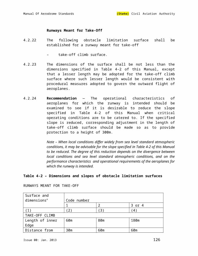
Manual Of Aerodrome Standards (State) Civil Aviation Authority
5.3.4.22 The approach lighting system shall consist of a row of lights on the extended centre line of the runway, extending, wherever possible, over a distance of 900 m from the runway threshold. In addition, the system shall have two side rows of lights, extending 270 m from the threshold, and two crossbars, one at 150 m and one at 300 m from the threshold, all as shown in ICAO Annex 14, Vol. I, Figure 5-14. Where the serviceability level of the approach lights specified as maintenance objectives in section 10.4.7 can be demonstrated, the system may have two side rows of lights, extending 240 m from the threshold, and two crossbars, one at 150 m and one at 300 m from the threshold, all as shown in ICAO Annex 14 ,Vol. I, Figure 5-15.
Note — The length of 900 m is based on providing guidance for operations under category I, II and III conditions. Reduced lengths may support category II and III operations but may impose limitations on category I operations. see Attachment A, Section 11.
5.3.4.23 The lights forming the centre line shall be placed at longitudinal intervals of 30 m with the innermost lights located 30 m from the threshold.
5.3.4.24 The lights forming the side rows shall be placed on each side of the centre line, at a longitudinal spacing equal to that of the centre line lights and with the first light located 30 m from the threshold. Where the serviceability level of the approach lights specified as maintenance objectives in section 10.4.7 of this Manual can be demonstrated, lights forming the side rows may be placed on each side of the centre line, at a longitudinal spacing of 60 m with the first light located 60 m from the threshold. The lateral spacing (or gauge) between the innermost lights of the side rows shall be not less than 18 m nor more than 22.5 m, and preferably 18 m, but in any event shall be equal to that of the touchdown zone lights.
5.3.4.25 The crossbar provided at 150 m from the threshold shall fill in the gaps between the centre line and side row lights.
5.3.4.26 The crossbar provided at 300 m from the threshold shall extend on both sides of the centre line lights to a distance of 15 m from the centre line.
5.3.4.27 If the centre line beyond a distance of 300 m from the threshold consists of lights as described in section 5.3.4.31 (b) or 5.3.4.32 (b) , additional crossbars of lights shall be provided at 450 m, 600 m and 750 m from the threshold.
5.3.4.28 Where the additional crossbars described in section 5.3.4.27 are incorporated in the system, the outer ends of these crossbars shall lie on two straight lines that either are parallel to the centre line or converge to meet the runway centre line 300 m from the threshold.
5.3.4.29 The system shall lie as nearly as practicable in the horizontal plane passing through the threshold, provided that:
Issue 00: Jan. 2013 126

Manual Of Aerodrome Standards (State) Civil Aviation Authority
(a) no object other than an ILS or MLS azimuth antenna shall protrude through the plane of the approach lights within a distance of 60 m from the centre line of the system; and
(b) no light other than a light located within the central part of a crossbar or a centre line barrette (not their extremities) shall be screened from an approaching aircraft.
Any ILS or MLS azimuth antenna protruding through the plane of the lights shall be treated as an obstacle and marked and lighted accordingly.
Characteristics
5.3.4.30 The centre line of a precision approach category II and III lighting system for the first 300 m from the threshold shall consist of barrettes showing variable white, except that, where the threshold is displaced 300 m or more, the centre line may consist of single light sources showing variable white. Where the serviceability level of the approach lights specified as maintenance objectives in section 10. 4.7 can be demonstrated, the centre line of a precision approach category II and III lighting system for the first 300 m from the threshold may consist of either:
(a) barrettes, where the centre line beyond 300 m from the threshold consists of barrettes as described in section 5.3.4.32 (a); or
(b) alternate single light sources and barrettes, where the centre line beyond 300 m from the threshold consists of single light sources as described in section 5.3.4.32 (b), with the innermost single light source located 30 m and the innermost barrette located 60 m from the threshold; or
(c) single light sources where the threshold is displaced 300 m or more; all of which shall show variable white.
5.3.4.31 Beyond 300 m from the threshold each centre line light position shall consist of either:
(a) a barrette as used on the inner 300 m; or
(b) two light sources in the central 300 m of the centre line and three light sources in the outer 300 m of the centre line; all of which shall show variable white.
5.3.4.32 Where the serviceability level of the approach lights specified as maintenance objectives in Attachment Asection 14.7 can be demonstrated, beyond 300 m from the threshold each centre line light position may consist of either:
(a) a barrette; or
(b) a single light source;
all of which shall show variable white.
Issue 00: Jan. 2013 127

Manual Of Aerodrome Standards (State) Civil Aviation Authority
5.3.4.33 The barrettes shall be at least 4 m in length. When barrettes are composed of lights approximating to point sources, the lights shall be uniformly spaced at intervals of not more than 1.5 m.
5.3.4.34 Recommendation — If the centre line beyond 300 m from the threshold consists of barrettes as described in section (5.3.4.31(a) or (5.3.4.32 (a)), each barrette beyond 300 m should be supplemented by a capacitor discharge light, except where such lighting is considered unnecessary taking into account the characteristics of the system and the nature of the meteorological conditions.
5.3.4.35 Each capacitor discharge light shall be flashed twice a second in sequence, beginning with the outermost light and progressing toward the threshold to the innermost light of the system. The design of the electrical circuit shall be such that these lights can be operated independently of the other lights of the approach lighting system.
5.3.4.36 The side row shall consist of barrettes showing red. The length of a side row barrette and the spacing of its lights shall be equal to those of the touchdown zone light barrettes.
5.3.4.37 The lights forming the crossbars shall be fixed lights showing variable white. The lights shall be uniformly spaced at intervals of not more than 2.7 m.
5.3.4.38 The intensity of the red lights shall be compatible with the intensity of the white lights.
5.3.4.39 The lights shall be in accordance with the specifications of ICAO Annex 14, Vol. I, Appendix 2, Figures A2-1 and A2-2.
Note — The flight path envelopes used in the design of these lights are given in ICAO Annex 14, Vol. I Attachment A, Figure A-4.
Visual Approach Slope Indicator Systems
Application
5.3.5.1 A visual approach slope indicator system shall be provided to serve the approach to a runway whether or not the runway is served by other visual approach aids or by non-visual aids, where one or more of the following conditions exist:
(a) the runway is used by turbojet or other aeroplanes with similar approach guidance requirements;
(b) the pilot of any type of aeroplane may have difficulty in judging the approach due to:
(1) inadequate visual guidance such as is experienced during an approach over water or featureless terrain by day or in the
Issue 00: Jan. 2013 128
Manual Of Aerodrome Standards (State) Civil Aviation Authority
absence of sufficient extraneous lights in the approach area by night, or
(2) misleading information such as is produced by deceptive surrounding terrain or runway slopes;
(c) the presence of objects in the approach area may involve serious hazard if an aeroplane descends below the normal approach path, particularly if there are no non-visual or other visual aids to give warning of such objects;
(d) physical conditions at either end of the runway present a serious hazard in the event of an aeroplane undershooting or overrunning the runway; and
(e) terrain or prevalent meteorological conditions are such that the aeroplane may be subjected to unusual turbulence during approach.
Note — Guidance on the priority of installation of visual approach slope indicator systems is contained in ICAO Annex 14, Vol. 1 Attachment A, Section 12.
5.3.5.2 The standard visual approach slope indicator systems shall consist of the following:
(a) T-VASIS and AT-VASIS conforming to the specifications contained in 5.3.5.6 to 5.3.5.22 inclusive;
(b) PAPI and APAPI systems conforming to the specifications contained in sections 5.3.5.23 to 5.3.5.40 inclusive; as shown in ICAO Annex 14,Vol.I, Figure 5-16.
5.3.5.3 PAPI, T-VASIS or AT-VASIS shall be provided where the code number is 3 or 4 when one or more of the conditions specified in section 5.3.5.1 of this Part exist.
5.3.5.4 PAPI or APAPI shall be provided where the code number is 1 or 2 when one or more of the conditions specified in section 5.3.5.1 of this Part exist.
5.3.5.5 Recommendation — Where a runway threshold is temporarily displaced from the normal position and one or more of the conditions specified in section 5.3.5.1 of this Part exist, a PAPI should be provided except that where the code number is 1 or 2 an APAPI may be provided.
T-VASIS and AT-VASIS
Description
5.3.5.6 The T-VASIS shall consist of twenty light units symmetrically disposed about the runway centre line in the form of two wing bars of four light units each, with bisecting longitudinal lines of six lights, as shown in ICAO Annex 14, Vol. I, Figure 5-17.
Issue 00: Jan. 2013 129

Manual Of Aerodrome Standards (State) Civil Aviation Authority
5.3.5.7 The AT-VASIS shall consist of ten light units arranged on one side of the runway in the form of a single wing bar of four light units with a bisecting longitudinal line of six lights.
5.3.5.8 The light units shall be constructed and arranged in such a manner that the pilot of an aeroplane during an approach will:
(a) when above the approach slope, see the wing bar(s) white, and one, two or three fly-down lights, the more fly-down lights being visible the higher the pilot is above the approach slope;
(b) when on the approach slope, see the wing bar(s) white; and
(c) when below the approach slope, see the wing bar(s) and one, two or three fly-up lights white, the more fly-up lights being visible the lower the pilot is below the approach slope; and when well below the approach slope, see the wing bar(s) and the three fly-up lights red.
When on or above the approach slope, no light shall be visible from the fly-up light units; when on or below the approach slope, no light shall be visible from the fly-down light units.
Siting
5.3.5.9 The light units shall be located as shown in ICAO Annex 14, Vol. I, Figure 5-17, subject to the installation tolerances given therein.
Note — The siting of T-VASIS will provide, for a 3° slope and a nominal eye height over the threshold of 15 m (See sections 5.3.5.6 and 5.3.5.19), a pilot’s eye height over threshold of 13m to 17 m when only the wing bar lights are visible. If increased eye height at the threshold is required (to provide adequate wheel clearance), then the approaches may be flown with one or more fly-down lights visible. The pilot’s eye height over the threshold is then of the following order:
Wing bar lights and one fly-down 17 m to 22 mlight visible
Wing bar lights and two fly-down 22 m to 28 mlights visible
Wing bar lights and three fly-down 28 m to 54 mlights visible
Characteristics of the Light Units
5.3.5.10 The systems shall be suitable for both day and night operations.
Issue 00: Jan. 2013 130
Manual Of Aerodrome Standards (State) Civil Aviation Authority
The light distribution of the beam of each light unit shall be of fan shape showing over a wide arc in azimuth in the approach direction. The wing bar light units shall produce a beam of white light from 1°54′vertical angle up to 6° vertical angle and a beam of red light from 0° to 1°54′vertical angle. The fly-down light units shall produce a white beam extending from an elevation of 6° down to approximately the approach slope, where it shall have a sharp cut-off. The fly-up light units shall produce a white beam from approximately the approach slope down to 1°54′vertical angle and a red beam below a 1°54′vertical angle. The angle of the top of the red beam in the wing bar units and fly-up units may be increased to comply with section 5.3.5.21.
5.3.5.12 The light intensity distribution of the fly-down, wing bar and fly-up light units shall be as shown in ICAO Annex 14, Vol. I, Appendix 2, Figure A2-22.
5.3.5.13 The colour transition from red to white in the vertical plane shall be such as to appear to an observer, at a distance of not less than 300 m, to occur over a vertical angle of not more than 15′.
5.3.5.14 At full intensity the red light shall have a Y coordinate not exceeding 0.320.
5.3.5.15 A suitable intensity control shall be provided to allow adjustments to meet the prevailing conditions and to avoid dazzling the pilot during approach and landing.
5.3.5.16 The light units forming the wing bars, or the light units forming a fly-down or a fly-up matched pair, shall be mounted so as to appear to the pilot of an approaching aeroplane to be substantially in a horizontal line. The light units shall be mounted as low as possible and shall be frangible.
5.3.5.17 The light units shall be so designed that deposits of condensation, dirt, etc., on optically transmitting or reflecting surfaces shall interfere to the least possible extent with the light signals and shall in no way affect the elevation of the beams or the contrast between the red and white signals. The construction of the light units shall be such as to minimize the probability of the slots being wholly or partially blocked by snow or ice where these conditions are likely to be encountered.
Approach Slope and Elevation Setting of Light Beams
5.3.5.18 The approach slope shall be appropriate for use by the aeroplanes using the approach.
5.3.5.19 When the runway on which a T-VASIS is provided is equipped with an ILS and/or MLS, the siting and elevations of the light units shall be such that the visual approach slope conforms as closely as possible with the glide path of the ILS and/or the minimum glide path of the MLS, as appropriate.
5.3.5.20 The elevation of the beams of the wing bar light units on both sides of the runway shall be the same. The elevation of the top of the beam of the fly-up light unit nearest to each wing bar, and that of the bottom of the beam of the fly-down light unit nearest to each wing bar, shall be equal and shall correspond to the
Issue 00: Jan. 2013 131
Manual Of Aerodrome Standards (State) Civil Aviation Authority
approach slope. The cut-off angle of the top of the beams of successive fly-up light units shall decrease by 5′of arc in angle of elevation at each successive unit away from the wing bar. The cut-in angle of the bottom of the beam of the fly-down light units shall increase by 7′ of arc at each successive unit away from the wing bar (See ICAO Annex 14, Vol. I, Figure 5-18).
5.3.5.21 The elevation setting of the top of the red light beams of the wing bar and fly-up light units shall be such that, during an approach, the pilot of an aeroplane to whom the wing bar and three fly-up light units are visible would clear all objects in the approach area by a safe margin if any such light did not appear red.
5.3.5.22 The azimuth spread of the light beam shall be suitably restricted where an object located outside the obstacle protection surface of the system, but within the lateral limits of its light beam, is found to extend above the plane of the obstacle protection surface and an aeronautical study indicates that the object could adversely affect the safety of operations. The extent of the restriction shall be such that the object remains outside the confines of the light beam.
Note — See sections 5.3.5.41 to 5.3.5.45 concerning the related obstacle protection surface.
PAPI and APAPI
Description
5.3.5.23 The PAPI system shall consist of a wing bar of 4 sharp transition multi-lamp (or paired single lamp) units equally spaced. The system shall be located on the left side of the runway unless it is physically impracticable to do so.
Note — Where a runway is used by aircraft requiring visual roll guidance which is not provided by other external means, then a second wing bar may be provided on the opposite side of the runway.
5.3.5.24 The APAPI system shall consist of a wing bar of 2 sharp transition multi-lamp (or paired single lamp) units. The system shall be located on the left side of the runway unless it is physically impracticable to do so.
Note — Where a runway is used by aircraft requiring visual roll guidance which is not provided by other external means, then a second wing bar may be provided on the opposite side of the runway.
5.3.5.25 The wing bar of a PAPI shall be constructed and arranged in such a manner that a pilot making an approach will:
(a) when on or close to the approach slope, see the two units nearest the runway as red and the two units farthest from the runway as white;
(b) when above the approach slope, see the one unit nearest the runway as red and the three units farthest from the runway as white; and when further above the approach slope, see all the units as white; and
Issue 00: Jan. 2013 132
Manual Of Aerodrome Standards (State) Civil Aviation Authority
(c) when below the approach slope, see the three units nearest the runway as red and the unit farthest from the runway as white; and when further below the approach slope, see all the units as red.
5.3.5.26 The wing bar of an APAPI shall be constructed and arranged in such a manner that a pilot making an approach will:
(a) when on or close to the approach slope, see the unit nearer the runway as red and the unit farther from the runway as white;
(b) when above the approach slope, see both the units as white; and
(c) when below the approach slope, see both the units as red.
Siting
5.3.5.27 The light units shall be located as in the basic configuration illustrated in ICAO Annex 14, Vol. I, Figure 5-19, subject to the installation tolerances given therein. The units forming a wing bar shall be mounted so as to appear to the pilot of an approaching aeroplane to be substantially in a horizontal line. The light units shall be mounted as low as possible and shall be frangible.
Characteristics of the Light Units
5.3.5.28 The system shall be suitable for both day and night operations.
5.3.5.29 The colour transition from red to white in the vertical plane shall be such as to appear to an observer, at a distance of not less than 300 m, to occur within a vertical angle of not more than 3’.
5.3.5.30 At full intensity the red light shall have a Y coordinate not exceeding 0.320.
5.3.5.31 The light intensity distribution of the light units shall be as shown in ICAO Annex 14, Vol. I, Appendix 2, Figure A2-23.
Note — See the ICAO Aerodrome Design Manual(Doc 9157), Part 4 for additional guidance on the characteristics of light units.
5.3.5.32 Suitable intensity control shall be provided so as to allow adjustment to meet the prevailing conditions and to avoid dazzling the pilot during approach and landing.
5.3.5.33 Each light unit shall be capable of adjustment in elevation so that the lower limit of the white part of the beam may be fixed at any desired angle of elevation between 1°30′and at least 4°30′above the horizontal.
5.3.5.34 The light units shall be so designed that deposits of condensation, dirt, etc., on optically transmitting or reflecting surfaces shall interfere to the least
possible extent with the light signals and shall not affect the contrast between the red and white signals and the elevation of the transition sector.
Issue 00: Jan. 2013 133

Manual Of Aerodrome Standards (State) Civil Aviation Authority
Approach Slope and Elevation Setting of Light Units
5.3.5.35 The approach slope as defined in ICAO Annex 14, Vol. I, Figure 5-20 shall be appropriate for use by the aeroplanes using the approach.
5.3.5.36 When the runway is equipped with an ILS and/or MLS, the siting and the angle of elevation of the light units shall be such that the visual approach slope conforms as closely as possible with the glide path of the ILS and/or the minimum glide path of the MLS, as appropriate.
5.3.5.37 The angle of elevation settings of the light units in a PAPI wing bar shall be such that, during an approach, the pilot of an aeroplane observing a signal of one white and three reds will clear all objects in the approach area by a safe margin (See Table 5-2).
5.3.5.38 The angle of elevation settings of the light units in an APAPI wing bar shall be such that, during an approach, the pilot of an aeroplane observing the lowest on slope signal, i.e. one white and one red, will clear all objects in the approach area by a safe margin (See Table 5-2).
5.3.5.39 The azimuth spread of the light beam shall be suitably restricted where an object located outside the obstacle protection surface of the PAPI or APAPI system, but within the lateral limits of its light beam, is found to extend above the plane of the obstacle protection surface and an aeronautical study indicates that the object could adversely affect the safety of operations. The extent of the restriction shall be such that the object remains outside the confines of the light beam.
Note — See sections 5.3.5.41 to 5.3.5.45 concerning the related obstacle protection surface.
5.3.5.40 Where wing bars are installed on each side of the runway to provide roll guidance, corresponding units shall be set at the same angle so that the signals of each wing bar change symmetrically at the same time.
Obstacle Protection Surface
Note — The following specifications apply to T-VASIS, AT-VASIS, PAPI and APAPI.
5.3.5.41 An obstacle protection surface shall be established when it is intended to provide a visual approach slope indicator system.
The characteristics of the obstacle protection surface, i.e. origin, divergence, length and slope shall correspond to those specified in the relevant
column of Table 5-3 and in ICAO Annex 14, Vol. I, Figure 5-21
Table 5-2: Wheel Clearance over Threshold for PAPI and APAPI
Eye-to-wheel height of Desired wheel clearance Minimum wheel clearance
Issue 00: Jan. 2013 134
Manual Of Aerodrome Standards (State) Civil Aviation Authority
aeroplane in the approach configurationa
(metres)b,c (metres)d
(1) (2) (3)up to but not including 3 m 6 3e
3 m up to but not including 5 m 9 45 m up to but not including 8 m 9 58 m up to but not including 14 m 9 6
a. In selecting the eye-to-wheel height group, only aeroplanes meant to use the system on a regular basis shall be considered. the most demanding amongst such aeroplanes shall determine the eye-to-wheel height group.
b. Where practicable the desired wheel clearances shown in column (2) shall be provided.c. The wheel clearances in column (2) may be reduced to no less than those in column (3)
where an aeronautical study indicates that such reduced wheel clearances are acceptable.
d. When a reduced wheel clearance is provided at a displaced threshold it shall be ensured that the corresponding desired wheel clearance specified in column (2) will be available when an aeroplane at the top end of the eye-to-wheel height group chosen overflies the extremity of the runway.
e. This wheel clearance may be reduced to 1.5 m on runways used mainly by light-weight non-turbo-jet aeroplanes.
Table 9-3 – Dimensions and Slopes of the Obstacles Protection SurfaceRunway type/code numberNon-instrument Instrument
SurfaceDimensions
Code number Code number1 2 3 4 1 2 3 4
Length ofinner edge
60 m 80 ma 150 m 150 m 150 m 150 m 300 m 300 m
Distancefromthreshold
30 m 60 m 60 m 60 m 60 m 60 m 60 m 60 m
Divergence(each side)
10% 10% 10% 10% 15% 15% 15% 15%
TotalLength
7500m 7500mb 15000 m 15000 m 7500 m 7500mb 15 000m 15 000m
Slopea) T-VASISand ATVASIS
-c 1.9° 1.9° 1.9° -1.9° 1.9° 1.9°
b) PAPId - A-0.57° A-0.57° A-0.57° A-0.57° A-0.57° A-0.57° A-0.57°c) APAPId A-0.9° A-0.9° - - A-0.9° A-0.9° - -
a. This length is to be increased to 150 m for a T-VASIS and AT-VASIS.b. This length is to be increased to 15 000 m for a T-VASIS and AT-VASIS.c. No slope has been specified if a system is unlikely to be used on runway type/code
number indicated.d. Angles as indicated in ICAO Annex 14 Vol. I Figure 5-20.
Issue 00: Jan. 2013 135

Manual Of Aerodrome Standards (State) Civil Aviation Authority
5.3.5.43 New objects or extensions of existing objects shall not be permitted above an obstacle protection surface except when, in the opinion of the Authority,
the new object or extension would be shielded by an existing immovable object.
Note — Circumstances in which the shielding principle may reasonably be applied are described in the ICAO Airport Services Manual(Doc 9137),
Part 6.
5.3.5.44 Existing objects above an obstacle protection surface shall be removed except when, in the opinion of the Authority, the object is shielded by an existing immovable object, or after aeronautical study it is determined that the object would not adversely affect the safety of operations of aeroplanes.
5.3.5.45 Where an aeronautical study indicates that an existing object extending above an obstacle protection surface could adversely affect the safety of operations of aeroplanes one or more of the following measures shall be taken:
(a) suitably raise the approach slope of the system;
(b) reduce the azimuth spread of the system so that the object is outside the confines of the beam;
(c) displace the axis of the system and its associated obstacle protection surface by no more than 5°;
(d) suitably displace the threshold; and
(e) where (d) is found to be impracticable, suitably displace the system upwind of the threshold to provide an increase in threshold crossing height equal to the height of the object penetration.
Note — Guidance on this issue is contained in the ICAO Aerodrome Design Manual(Doc 9157), Part 4.
5.3.6 Circling Guidance Lights
Application
5.3.6.1 Recommendation — Circling guidance lights should be provided when existing approach and runway lighting systems do not satisfactorily permit identification of the runway and/or approach area to a circling aircraft in the conditions for which it is intended the runway be used for circling approaches.
Location
5.3.6.2 Recommendation — The location and number of circling guidance lights should be adequate to enable a pilot, as appropriate, to:
Issue 00: Jan. 2013 136

Manual Of Aerodrome Standards (State) Civil Aviation Authority
(a) join the downwind leg or align and adjust the aircraft’s track to the runway at a required distance from it and to distinguish the threshold in passing; and
b) keep in sight the runway threshold and/or other features which will make it possible to judge the turn on to base leg and final approach, taking into account the guidance provided by other
visual aids.
5.3.6.3 Recommendation — Circling guidance lights should consist of:
(a) lights indicating the extended centre line of the runway and/orparts of any approach lighting system; or
(b) lights indicating the position of the runway threshold; or
(c) lights indicating the direction or location of the runway;
(e) or a combination of such lights as is appropriate to the runway under consideration.
Note — Guidance on installation of circling guidance lights is given in the ICAO Aerodrome Design Manual(Doc 9157), Part 4.
Characteristics
5.3.6.4 Recommendation — Circling guidance lights should be fixed or flashing lights of an intensity and beam spread adequate for the conditions of visibility and ambient light in which it is intended to make visual circling approaches. The flashing lights should be white, and the steady lights either white or gaseous discharge lights.
5.3.6.5 Recommendation — The lights should be designed and be installed in such a manner that they will not dazzle or confuse a pilot when approaching to land, taking off or taxiing.
5.3.7 Runway Lead-In Lighting Systems
Application5.3.7.1 Recommendation — A runway lead-in lighting system should be provided
where it is desired to provide visual guidance along a specific approach path, for reasons such as avoiding hazardous terrain or for purposes of noise abatement.Note — Guidance on providing lead-in lighting systems is given in the ICAO .Aerodrome Design Manual(Doc 9157), Part 4.
Location
5.3.7.2 Recommendation — A runway lead-in lighting system should consist of groups of lights positioned so as to define the desired approach path and so that one
Issue 00: Jan. 2013 137
Manual Of Aerodrome Standards (State) Civil Aviation Authority
group may be sighted from the preceding group. The interval between adjacent groups should not exceed approximately 1 600 m.
Note — Runway lead-in lighting systems may be curved, straight or a combination thereof.
5.3.7.3 Recommendation — A runway lead-in lighting system should extend from a point as determined by the Authority, up to a point where the approach lighting system, if provided, or the runway or the runway lighting system is in view.
Characteristics
5.3.7.4 Recommendation — Each group of lights of a runway lead-in lighting system should consist of at least three flashing lights in a linear or cluster configuration. The system may be augmented by steady burning lights where such lights would assist in identifying the system.
5.3.7.5 Recommendation — The flashing lights should be white, and the steady burning lights gaseous discharge lights.
5.3.7.6 Recommendation — Where practicable, the flashing lights in each group should flash in sequence towards the runway.
5.3.8 Runway Threshold Identification Lights
Application
5.3.8.1 Recommendation — Runway threshold identification lights should be installed:
(a) at the threshold of a non-precision approach runway when additional threshold conspicuity is necessary or where it is not practicable to provide other approach lighting aids; and
(b) where a runway threshold is permanently displaced from the runway extremity or temporarily displaced from the position and additional threshold conspicuity is necessary.
Location
5.3.8.2 Runway threshold identification lights shall be located symmetrically about the runway centre line, in line with the threshold and approximately 10 m outside each line of runway edge lights.
Characteristics
5.3.8.3 Recommendation — Runway threshold identification lights should be flashing white lights with a flash frequency between 60 and 120 per minute.
5.3.8.4 The lights shall be visible only in the direction of approach to the runway.
Issue 00: Jan. 2013 138

Manual Of Aerodrome Standards (State) Civil Aviation Authority
5.3.9 Runway Edge Lights
Application
5.3.9.1 Runway edge lights shall be provided for a runway intended for use at night or for a precision approach runway intended for use by day or night.
5.3.9.2 Recommendation — Runway edge lights should be provided on a runway intended for take-off with an operating minimum below an RVR of the
order of 800 m by day.
Location
5.3.9.3 Runway edge lights shall be placed along the full length of the runway and shall be in two parallel rows equidistant from the centre line.
5.3.9.4 Runway edge lights shall be placed along the edges of the area declared for use as the runway or outside the edges of the area at a distance of not more than 3 m.
5.3.9.5 Recommendation — Where the width of the area which could be declared as runway exceeds 60 m, the distance between the rows of lights should be determined taking into account the nature of the operations, the light distribution characteristics of the runway edge lights, and other visual aids serving the runway.
5.3.9.6 The lights shall be uniformly spaced in rows at intervals of not more than 60 m for an instrument runway, and at intervals of not more than 100 m for a non-instrument runway. The lights on opposite sides of the runway axis shall be on lines at right angles to that axis. At intersections of runways, lights may be spaced irregularly or omitted, provided that adequate guidance remains available to the pilot.
Characteristics
5.3.9.7 Runway edge lights shall be fixed lights showing variable white, except that:
(a) in the case of a displaced threshold, the lights between the beginning of the runway and the displaced threshold shall show red in the approach direction; and
(b) a section of the lights 600 m or one-third of the runway length, whichever is the less, at the remote end of the runway from the end at which the take-off run is started, may show yellow.
5.3.9.8 The runway edge lights shall show at all angles in azimuth necessary to provide guidance to a pilot landing or taking off in either direction. When the runway edge lights are intended to provide circling guidance, they shall show at all angles in azimuth (See section 5.3.6.1).
Issue 00: Jan. 2013 139

Manual Of Aerodrome Standards (State) Civil Aviation Authority
5.3.9.9 In all angles of azimuth required in section 5.3.9.8 of this Part, runway edge lights shall show at angles up to 15° above the horizontal with an intensity adequate for the conditions of visibility and ambient light in which use of the runway for take-off or landing is intended. In any case, the intensity shall be at least 50 cd except that at an aerodrome without extraneous lighting the intensity of the lights may be reduced to not less than 25 cd to avoid dazzling the pilot.
5.3.9.10 Runway edge lights on a precision approach runway shall be in accordance with the specifications of ICAO Annex 14, Vol. I, Appendix 2, Figure A2-9 or A2-10.
5.3.10 Runway Threshold and Wing Bar Lights(See ICAO Annex 14 Vol. I, Figure 5-22)
Application of Runway Threshold Lights
5.3.10.1 Runway threshold lights shall be provided for a runway equipped with runway edge lights except on a non-instrument or non-precision approach runway where the threshold is displaced and wing bar lights are provided.
Location of Runway Threshold Lights
5.3.10.2 When a threshold is at the extremity of a runway, the threshold lights shall be placed in a row at right angles to the runway axis as near to the extremity of the runway as possible and, in any case, not more than 3 m outside the extremity.
5.3.10.3 When a threshold is displaced from the extremity of a runway, threshold lights shall be placed in a row at right angles to the runway axis at the displaced threshold.
5.3.10.4 Threshold lighting shall consist of:
(a) on a non-instrument or non-precision approach runway, at least six lights;
(b) on a precision approach runway category I, at least the number of lights that would be required if the lights were uniformly spaced at intervals of 3 m between the rows of runway edge lights; and
(c) on a precision approach runway category II or III, lights uniformly spaced between the rows of runway edge lights at intervals of not more than 3 m.
5.3.10.5 Recommendation — The lights prescribed in section 5.3.10.4 (a) and (b) should be either:
(a) equally spaced between the rows of runway edge lights, or
(b) symmetrically disposed about the runway centre line in two groups, with the lights uniformly spaced in each group and with a gap between the groups equal to the gauge of the touchdown zone marking or lighting,
Issue 00: Jan. 2013 140
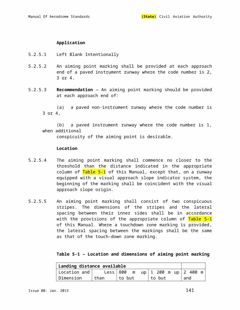
Manual Of Aerodrome Standards (State) Civil Aviation Authority
where such is provided, or otherwise not more than half the distance between the rows of runway edge lights.
Application of Wing Bar Lights
5.3.10.6 Recommendation — Wing bar lights should be provided on a precision approach runway when additional conspicuity is considered desirable.
5.3.10.7 Wing bar lights shall be provided on a non-instrument or non-precision approach runway where the threshold is displaced and runway threshold lights are required, but are not provided.
Location of Wing Bar Lights
5.3.10.8 Wing bar lights shall be symmetrically disposed about the runway centre line at the threshold in two groups, i.e. wing bars. Each wing bar shall be formed by at least five lights extending at least 10 m outward from, and at right angles to, the line of the runway edge lights, with the innermost light of each wing bar in the line of the runway edge lights.
Characteristics of Runway Threshold and Wing Bar Lights
5.3.10.9 Runway threshold and wing bar lights shall be fixed unidirectional lights showing green in the direction of approach to the runway. The intensity and beam spread of the lights shall be adequate for the conditions of visibility and ambient light in which use of the runway is intended.
5.3.10.10 Runway threshold lights on a precision approach runway shall be in accordance with the specifications of ICAO Annex 14, Vol. I, Appendix 2, Figure A2-3.
5.3.10.11 Threshold wing bar lights on a precision approach runway shall be in accordance with the specifications of ICAO Annex 14, Vol. I, Appendix 2, Figure A2-4.
5.3.11 Runway End Lights
(See ICAO Annex 14, Vol. I, Figure 5-22)
Application
5.3.11.1 Runway end lights shall be provided for a runway equipped with runway edge lights.
Note — When the threshold is at the runway extremity, fittings serving as threshold lights may be used as runway end lights.
Location
5.3.11.2 Runway end lights shall be placed on a line at right angles to the runway axis as near to the end of the runway as possible and, in any case, not more than 3 m outside the end.
Issue 00: Jan. 2013 141

Manual Of Aerodrome Standards (State) Civil Aviation Authority
5.3.11.3 Recommendation — Runway end lighting should consist of at least six lights. The lights should be either:
(a) equally spaced between the rows of runway edge lights, or
(c) symmetrically disposed about the runway centre line in two groups with the lights uniformly spaced in each group and with a gap between the groups of not more than half the distance between the rows of runway edge lights.
For a precision approach runway category III, the spacing between runway end lights, except between the two innermost lights if a gap is used, should not exceed 6 m.
Characteristics
5.3.11.4 Runway end lights shall be fixed unidirectional lights showing red in the direction of the runway. The intensity and beam spread of the lights shall be adequate for the conditions of visibility and ambient light in which use of the runway is intended.
5.3.11.5 Runway end lights on a precision approach runway shall be in accordance with the specifications of ICAO Annex 14, Vol. I, Appendix 2, Figure A2-8.
5.3.12 Runway Centre Line Lights
Application
5.3.12.1 Runway centre line lights shall be provided on a precision approach runway category II or III.
5.3.12.2 Recommendation — Runway centre line lights should be provided on a precision approach runway category I, particularly when the runway is used by aircraft with high landing speeds or where the width between the runway edge lights is greater than 50 m.
5.3.12.3 Runway centre line lights shall be provided on a runway intended to be used for take-off with an operating minimum below an RVR of the order of 400 m.
5.3.12.4 Recommendation — Runway centre line lights should be provided on a runway intended to be used for take-off with an operating minimum of an RVR of the order of 400 m or higher when used by aeroplanes with a very high take-off speed, particularly where the width between the runway edge lights is greater than 50 m.
Location
5.3.12.5 Runway centre line lights shall be located along the centre line of the runway, except that the lights may be uniformly offset to the same side of the runway
Issue 00: Jan. 2013 142

Manual Of Aerodrome Standards (State) Civil Aviation Authority
centre line by not more than 60 cm where it is not practicable to locate them along the centre line. The lights shall be located from the threshold to the end at longitudinal spacing of approximately 15 m. Where the serviceability level of the runway centre line lights specified as maintenance objectives in section 10.4.7 or 10.4.11 of this Manual, as appropriate, can be demonstrated and the runway is intended for use in runway visual range conditions of 350 m or greater, the longitudinal spacing may be approximately 30 m.
Note — Existing centre line lighting where lights are spaced at 7.5 m need not be replaced.
5.3.12.6 Recommendation — Centre line guidance for take-off from the beginning of a runway to a displaced threshold should be provided by:
(a) an approach lighting system if its characteristics and intensity settings afford the guidance required during take-off and it does not dazzle the pilot of an aircraft taking off; or
(b) runway centre line lights; or
(c) barrettes of at least 3 m length and spaced at uniform intervals of 30 m, as shown in ICAO Annex 14 Vol. I, Figure 5-23, designed so that their photometric characteristics and intensity setting afford the guidance required during take-off without dazzling the pilot of an aircraft taking off.
Where necessary, provision should be made to extinguish those centre line lights specified in b) or reset the intensity of the approach lighting system or barrettes when the runway is being used for landing. In no case should only the single source runway centre line lights show from the beginning of the runway to a displaced threshold when the runway is being used for landing.
Characteristics
5.3.12.7 Runway centre line lights shall be fixed lights showing variable white from the threshold to the point 900 m from the runway end; alternate red and variable white from 900 m to 300 m from the runway end; and red from 300 m to the runway end, except that for runways less than 1 800 m in length, the alternate red and variable white lights shall extend from the mid-point of the runway usable for landing to 300 m from the runway end.
Note — Care is required in the design of the electrical system to ensure that failure of part of the electrical system will not result in a false indication of the runway distance remaining.
5.3.12.8 Runway centre line lights shall be in accordance with the specifications of ICAO Annex 14 Vol. I, Appendix 2, Figure A2-6 or A2-7.
5.3.13 Runway Touchdown Zone Lights
Application
Issue 00: Jan. 2013 143
Manual Of Aerodrome Standards (State) Civil Aviation Authority
5.3.13.1 Touchdown zone lights shall be provided in the touchdown zone of a precision approach runway category II or III.
Location
5.3.13.2 Touchdown zone lights shall extend from the threshold for a longitudinal distance of 900 m, except that, on runways less than 1800 m in length, the system shall be shortened so that it does not extend beyond the midpoint of the runway. The pattern shall be formed by pairs of barrettes symmetrically located about the runway centre line. The lateral spacing between the innermost lights of a pair of barrettes shall be equal to the lateral spacing selected for the touchdown zone marking. The longitudinal spacing between pairs of barrettes shall be either 30 m or 60 m.
Note — To allow for operations at lower visibility minima, it may be advisable to use a 30 m longitudinal spacing between barrettes.
Characteristics
5.3.13.3 A barrette shall be composed of at least three lights with a spacing between the lights of not more than 1.5m.
5.3.13.4 Recommendation— A barrette should be not less than 3 m nor more than 4.5m in length.
5.3.13.5 Touchdown zone lights shall be fixed uni-directional lights showing variable white.
5.3.13.6 Touchdown zone lights shall be in accordance with the specifications of ICAO Annex 14, Vol. I, Appendix 2, Figure A2-5.
5.3.14 Rapid Exit Taxiway Indicator Lights
Note.— The purpose of rapid exit taxiway indicator lights (RETILs) is to provide pilots with distance-to-go information to the nearest rapid exit taxiway on the runway, to enhance situational awareness in low visibility conditions and enable pilots to apply braking action for more efficient roll-out and runway exit speeds. It is essential that pilots operating at aerodromes with runway(s) displaying rapid exit taxiway indicator lights be familiar with the purpose of these lights.
Application
5.3.14.1 Recommendation.— Rapid exit taxiway indicator lights should be provided on a runway intended for use in runway visual range conditions less than a value of 350 m and/or where the traffic density is heavy.
Note.— See ICAO Annex 14 volume I Attachment A, Section 14.
Issue 00: Jan. 2013 144
Manual Of Aerodrome Standards (State) Civil Aviation Authority
5.3.14.2 Rapid exit taxiway indicator lights shall not be displayed in the event of any lamp failure or other failure that prevents the display of the light pattern depicted in ICAO Annex 14 volume I Figure 5-24, in full.
Location
5.3.14.3 A set of rapid exit taxiway indicator lights shall be located on the runway on the same side of the runway centre line as the associated rapid exit taxiway, in the configuration shown in ICAO annex 14 volume I Figure 5-24. In each set, the lights shall be located 2 m apart and the light nearest to the runway centre line shall be displaced 2 m from the runway centre line.
5.3.14.4 Where more than one rapid exit taxiway exists on a runway, the set of rapid exit taxiway indicator lights for each exit shall not overlap when displayed.
Characteristics
5.3.14.5 Rapid exit taxiway indicator lights shall be fixed unidirectional yellow lights, aligned so as to be visible to the pilot of a landing aeroplane in the direction of approach to the runway. See Figure 5-24 of ICAO Annex 14 volume I for an illustration of rapid exit taxiway indicator lights (RETILs)
5.3.14.6 Rapid exit taxiway indicator lights shall be in accordance with the specifications in ICAO Annex 14 volume I Appendix 2, Figure A2-6 or Figure A2-7, as appropriate.
5.3.14.7 Recommendation.— Rapid exit taxiway indicator lights should be supplied with power on a separate circuit to other runway lighting so that they may be used when other lighting is switched off.
5.3.15 Stopway Lights
Application
5.3.15.1 Stopway lights shall be provided for a stopway intended for use at night.
Location
5.3.15.2 Stopway lights shall be placed along the full length of the stopway and shall be in two parallel rows that are equidistant from the centre line and coincident with the rows of the runway edge lights. Stopway lights shall also be provided across the end of a stopway on a line at right angles to the stopway axis as near to the end of the stopway as possible and, in any case, not more than 3 m outside the end.
Characteristics
5.3.15.3 Stopway lights shall be fixed unidirectional lights showing red in the direction of the runway.
5.3.16 Taxiway Centre Line Lights
Issue 00: Jan. 2013 145
Manual Of Aerodrome Standards (State) Civil Aviation Authority
Application
9.2.3.16.1 Taxiway centre line lights shall be provided on an exit taxiway, facility and apron intended for use in runway visual range conditions less than a value of 350 m in such a manner as to provide continuous guidance between the runway centre line and aircraft stands, except that these lights need not be provided where the traffic density is light and taxiway edge lights and centre line marking provide adequate guidance.
5.3.16.2 Recommendation — Taxiway centre line lights should be provided on a taxiway intended for use at night in runway visual range conditions of 350 m or greater, and particularly on complex taxiway intersections and exit taxiways, except that these lights need not be provided where the traffic density is light and taxiway edge lights and centre line marking provide adequate guidance.
Note — Where there may be a need to delineate the edges of a taxiway, e.g. on a rapid exit taxiway, narrow taxiway, this may be done with taxiway edge lights or markers.
5.3.16.3 Recommendation — Taxiway centre line lights should be provided on an exit taxiway, taxiway and apron in all visibility conditions where specified as components of an advanced surface movement guidance and control system in such a manner as to provide continuous guidance between the runway centre line and aircraft stands.
5.3.16.4 Taxiway centre line lights shall be provided on a runway forming part of a standard taxi-route and intended for taxiing in runway visual range conditions less than a value of 350 m, except that these lights need not be provided where the traffic density is light and taxiway edge lights and centre line marking provide adequate guidance.
Note — See section 8.2.3 of this Part for provisions concerning the interlocking of runway and taxiway lighting systems.
5.3.16.5 Recommendation — Taxiway centre line lights should be provided in all visibility conditions on a runway forming part of a standard taxi-route where specified as components of an advanced surface movement guidance and control system.
Characteristics
5.3.16.6 Taxiway centre line lights on a taxiway other than an exit taxiway and on a runway forming part of a standard taxi-route shall be fixed lights showing green with beam dimensions such that the light is visible only from aeroplanes on or in the vicinity of the taxiway.
5.3.16.7 Taxiway centre line lights on an exit taxiway shall be fixed lights. Alternate taxiway centre line lights shall show green and yellow from their beginning near the runway centre line to the perimeter of the ILS/MLS critical/sensitive area or the lower edge of the inner transitional surface, whichever is farthest from the
Issue 00: Jan. 2013 146
Manual Of Aerodrome Standards (State) Civil Aviation Authority
runway; and thereafter all lights shall show green (See ICAO Annex 14, Vol. I, Figure 5-25). The light nearest to the perimeter shall always show yellow. Where aircraft may follow the same centre line in both directions, all the centre line lights shall show green to aircraft approaching the runway.
Note 1 — Care is necessary to limit the light distribution of green lights on or near a runway so as to avoid possible confusion with threshold lights.
Note 2 — For yellow filter characteristics see ICAO Annex 14, Vol. I, Appendix 1, 2.2.
Note 3 — The size of the ILS/MLS critical/sensitive area depends on the characteristics of the associated ILS/MLS and other factors. Guidance is provided in ICAO Annex 10, Volume I, Attachments C and G.
Note 4 — See section 5.4.3 for specifications on runway vacated signs.
5.3.16.8 Taxiway centre line lights shall be in accordance with the specifications of:
(a) ICAO Annex 14, Vol. I, Appendix 2, Figure A2-12, A2-13, or A2-14 for taxiways intended for use in runway visual range conditions of less than a value of 350 m; and
(b) ICAO Annex 14, Vol. I, Appendix 2, Figure A2-15 or A2-16 for other taxiways.
5.3.16.9 Recommendation—Where higher intensities are required, from an operational point of view, the taxiway centre line lights on rapid exit taxiways intended for use in runway visual range conditions less than a value of 350m should be in accordance with the specifications of ICAO Annex 14 Vol. I, Appendix 2, Figure A2-12. The number of levels of brilliancy setting for these lights should be the same as that for the runway centre line lights.
5.3.16.10 Recommendation — Where taxiway centre line lights are specified as components of an advanced surface movement guidance and control system and where, from an operational point of view, higher intensities are required to maintain ground movements at a certain speed in very low visibilities or in bright daytime conditions, taxiway centre line lights should be in accordance with the specifications of ICAO Annex 14, Vol. I, Appendix 2, Figure A2-17, A2-18 or A2-19.
Note — High-intensity centre line lights should only be used in case of an absolute necessity and following a specific study.
Location
5.3.16.11 Taxiway centre line lights shall normally be located on the taxiway centre line marking, except that they may be offset by not more than 30cm where it is not practicable to locate them on the marking.
Issue 00: Jan. 2013 147

Manual Of Aerodrome Standards (State) Civil Aviation Authority
Taxiway Centre Line Lights on Taxiways
Location
5.3.16.12 Taxiway centre line lights on a straight section of a taxiway shall be spaced at longitudinal intervals of not more than 30 m, except that:
(a) larger intervals not exceeding 60 m may be used where, because of the prevailing meteorological conditions, adequate guidance is
provided by such spacing;
(b) Intervals less than 30 m should be provided on short straight sections; and
(c) on a taxiway intended for use in RVR conditions of less than a value of 350 m, the longitudinal spacing should not exceed 15m.
5.3.16.13 Taxiway centre line lights on a taxiway curve shall continue from the straight portion of the taxiway at a constant distance from the outside edge of the taxiway curve. The lights should be spaced at intervals such that a clear indication of the curve is provided.
5.3.16.14 On a taxiway intended for use in RVR conditions of less than a value of 350 m, the lights on a curve shall not exceed a spacing of 15 m and on a curve of less than 400 m radius the lights should be spaced at intervals of not greater than 7.5m. This spacing should extend for 60 m before and after the curve.
Note 1 — Spacing’s on curves that have been found suitable for a taxiway intended for use in RVR conditions of 350 m or greater are:
Curve Radius Line Spacing
up to 400 m 7.5m
401 m to 899 m 15m
900 m or greater 30m
Note 2 — See section 3.9.6 and ICAO Annex 14, Vol. I, Figure 3-2.
Taxiway Centre Line Lights on Rapid Exit Taxiways
Location
5.3.16.15 Taxiway centre line lights on a rapid exit taxiway shall commence at a point at least 60 m before the beginning of the taxiway centre line curve and continue beyond the end of the curve to a point on the centre line of the taxiway where an
Issue 00: Jan. 2013 148
Manual Of Aerodrome Standards (State) Civil Aviation Authority
aeroplane can be expected to reach normal taxiing speed. The lights on that portion parallel to the runway centre line should always be at least 60 cm from any row of runway centre line lights, as shown in ICAO Annex 14, Vol. I, Figure 5-26.
5.3.16.16 The lights shall be spaced at longitudinal intervals of not more than 15m, except that, where runway centre line lights are not provided, a greater interval not exceeding 30 m may be used.
Taxiway Centre Line Lights on Other Exit Taxiways
Location
5.3.16.17 Recommendation — Taxiway centre line lights on exit taxiways other than rapid exit taxiways should commence at the point where the taxiway centre line marking begins to curve from the runway centre line, and follow the curved taxiway centre line marking at least to the point where the marking leaves the runway. The first light should be at least 60 cm from any row of runway centre line lights, as shown in ICAO Annex 14, Vol. I, Figure 5-26.
5.3.16.18 Recommendation — The lights should be spaced at longitudinal intervals of not more than 7.5 m.
Taxiway Centre Line Lights on Runways
Location
5.3.16.19 Recommendation — Taxiway centre line lights on a runway forming part of a standard taxi-route and intended for taxiing in runway visual range conditions less than a value of 350m should be spaced at longitudinal intervals not exceeding 15 m.
5.3.17 Taxiway Edge Lights
Application
5.3.17.1 Taxiway edge lights shall be provided at the edges of a runway turn pad, holding bay, apron, etc. intended for use at night and on a taxiway not provided with taxiway centre line lights and intended for use at night, except that taxiway edge lights need not be provided where, considering the nature of the operations, adequate guidance can be achieved by surface illumination or other means.
Note — See section 5.5.5 of this Part for taxiway edge markers.
5.3.17.2 Taxiway edge lights shall be provided on a runway forming part of a standard taxi-route and intended for taxiing at night where the runway is not provided with taxiway centre line lights.
Note — See section 8.2.3 of this Part for provisions concerning the inter-locking of runway and taxiway lighting systems.
Issue 00: Jan. 2013 149
Manual Of Aerodrome Standards (State) Civil Aviation Authority
Location
5.3.17.3 Taxiway edge lights on a straight section of a taxiway and on a runway forming part of a standard taxi-route shall be spaced at uniform longitudinal intervals of not more than 60m. The lights on a curve should be spaced at intervals less than 60m so that a clear indication of the curve is provided.
Note — Guidance on the spacing of taxiway edge lights on curves is given in the Aerodrome Design Manual (Doc 9157), Part 4.
5.3.17.4 Taxiway edge lights on a holding bay, apron, etc. shall be spaced at uniform longitudinal intervals of not more than 60 m.
5.3.17.5 Taxiway edge lights on a runway turn pad shall be spaced at uniform longitudinal intervals of not more than 30m
5.3.17.6 The lights shall be located as near as practicable to the edges of the taxiway, holding bay, apron or runway, etc. or outside the edges at a distance of not more than 3 m.
Characteristics
5.3.17.7 Taxiway edge lights shall be fixed lights showing blue. The lights shall show up to at least 75° above the horizontal and at all angles in azimuth necessary to provide guidance to a pilot taxiing in either direction. At an intersection, exit or curve the lights shall be shielded as far as practicable so that they cannot be seen in angles of azimuth in which they may be confused with other lights.
5.3.17.8 The intensity of taxiway edge lights shall be at least 2 cd from 0° to 6° vertical, and 0.2 cd at any vertical angles between 6° and 75°.
5.3.18 Runway Turn Pad Lights
Application
5.3.18.1 Runway turn pad lights shall be provided for continuous guidance on a runway turn pad intended for use in runway visual range conditions less than a value of 350 m, to enable an aeroplane to complete a 180-degree turn and align with the runway centre line.
5.3.18.2 Runway turn pad lights shall be provided on a runway turn pad intended for use at night.
Location
5.3.18.3 Runway turn pad lights shall normally be located on the runway turn pad marking, except that they may be offset by not more than 30 cm where it is not practicable to locate them on the marking.
Issue 00: Jan. 2013 150
Manual Of Aerodrome Standards (State) Civil Aviation Authority
5.3.18.4 Runway turn pad lights on a straight section of the runway turn pad marking shall be spaced at longitudinal intervals of not more than 15 m.
5.3.18.5 Runway turn pad lights on a curved section of the runway turn pad marking shall not exceed a spacing of 7.5 m.
Characteristics
5.3.18.6 Runway turn pad lights shall be unidirectional fixed lights showing green with beam dimensions such that the light is visible only from aeroplanes on or approaching the runway turn pad.
5.3.18.7 Runway turn pad lights shall be in accordance with the specifications of ICAO Annex 14 volume 1 Appendix 2, Figure A2-13, A2-14 or A2-15, as appropriate.
5.3.19 Stop Bars
Application
Note 1 — The provision of stop bars requires their control either manually or automatically by the air traffic services.
Note 2 — Runway incursions may take place in all visibility or weather conditions.
The provision of stop bars at runway holding positions and their use at night in visibility conditions greater than 550 m RVR can form part of effective runway incursion prevention measures.
5.3.19.1 A stop bar shall be provided at every runway-holding position serving a runway when it is intended that the runway will be used in runway visual range conditions less than a value of 350 m, except where:
(a) appropriate aids and procedures are available to assist in preventing inadvertent incursions of aircraft and vehicles onto the runway; or
(b) operational procedures exist to limit, in runway visual range conditions less than a value of 550 m, the number of:
(1) aircraft on the manoeuvring area to one at a time; and
(2) vehicles on the manoeuvring area to the essential minimum.
5.3.19.2 A stop bar shall be provided at every runway-holding position serving a runway when it is intended that the runway will be used in runway visual range conditions of values between 350 m and 550 m, except where:
(a) appropriate aids and procedures are available to assist in preventing inadvertent incursions of aircraft and vehicles onto the runway; or
Issue 00: Jan. 2013 151

Manual Of Aerodrome Standards (State) Civil Aviation Authority
(b) operational procedures exist to limit, in runway visual range conditions less than a value of 550 m, the number of:
(1) aircraft on the manoeuvring area to one at a time; and
(2) vehicles on the manoeuvring area to the essential minimum.
5.3.19.3 Recommendation — A stop bar should be provided at an intermediate holding position when it is desired to supplement markings with lights and to provide traffic control by visual means.
5.3.19.4 Where the normal stop bar lights might be obscured (from a pilot’s view), for example, by fog or rain, or where a pilot may be required to stop the aircraft in a position so close to the lights that they are blocked from view by the structure of the aircraft, then a pair of elevated lights shall be added to each end of the stop bar.
Location
5.3.19.5 Stop bars shall be located across the taxiway at the point where it is desired that traffic stop. Where the additional lights specified in section 5.3.19.4 of this Manual are provided, these lights shall be located not less than 3 m from the taxiway edge.
Characteristics
5.3.19.6 Stop bars shall consist of lights spaced at intervals of 3 m across the taxiway, showing red in the intended direction(s) of approach to the intersection or runway-holding position.
5.3.19.7 Stop bars installed at a runway-holding position shall be unidirectional and shall show red in the direction of approach to the runway.
5.3.19.8 Where the additional lights specified in section 5.3.19.4 of this Part are provided, these lights shall have the same characteristics as the lights in the stop bar, but shall be visible to approaching aircraft up to the stop bar position.
5.3.19.9 Selectively switchable stop bars shall be installed in conjunction with at least three taxiway centre line lights (extending for a distance of at least 90 m from the stop bar) in the direction that it is intended for an aircraft to proceed from the stop bar.
Note — See section 5.3.16.12 for provisions concerning the spacing of taxiway centre line lights.
5.3.19.10 The intensity in red light and beam spreads of stop bar lights shall be in accordance with the specifications in ICAO Annex 14, Vol. I, Appendix 2, Figures A2-12 through A2-16, as appropriate.
Issue 00: Jan. 2013 152
Manual Of Aerodrome Standards (State) Civil Aviation Authority
5.3.19.11 Recommendation — Where stop bars are specified as components of an advanced surface movement guidance and control system and where, from an operational point of view, higher intensities are required to maintain ground movements at a certain speed in very low visibilities or in bright daytime conditions, the intensity in red light and beam spreads of stop bar lights should be in accordance with the specifications of ICAO Annex 14 Vol. I, Appendix 2, Figure A2-17,A2-18 or A2-19.
Note — High-intensity stop bars should only be used in case of an absolute necessity and following a specific study.
5.3.19.12 Recommendation — Where a wide beam fixture is required, the intensity in red light and beam spreads of stop bar lights should be in accordance with the specifications of ICAO Annex 14 Vol. I, Appendix 2, Figure A2-17 or A2-19.
5.3.19.13 The lighting circuit shall be designed so that:
(a) stop bars located across entrance taxiways are selectively switchable;
(b) stop bars located across taxiways intended to be used only as exit taxiways are switchable selectively or in groups;
(c) when a stop bar is illuminated, any taxiway centre line lights installed beyond the stop bar shall be extinguished for a distance of at least 90 m; and
(d) stop bars shall be interlocked with the taxiway centre line lights so that when the centre line lights beyond the stop bar are illuminated the stop bar is extinguished and vice versa.
Note 1 — A stop bar is switched on to indicate that traffic stop and switched off to indicate that traffic proceed.
Note 2 — Care is required in the design of the electrical system to ensure that all of the lights of a stop bar will not fail at the same time. Guidance on this issue is given in the ICAO Aerodrome Design Manual (Doc 9157), Part 5.
5.3.20 Intermediate Holding Position Lights
Note — See section 5.2.11 of this Part for specifications on intermediate holding position marking.
Application
5.3.20.1 Except where a stop bar has been installed, intermediate holding position lights shall be provided at an intermediate holding position intended for use in runway visual range conditions less than a value of 350 m.
Issue 00: Jan. 2013 153

Manual Of Aerodrome Standards (State) Civil Aviation Authority
5.3.20.2 Recommendation — Intermediate holding position lights should be provided at an intermediate holding position where there is no need for stop-and-go signals as provided by a stop bar.
Location
5.3.20.3 Intermediate holding position lights shall be located along the intermediate holding position marking at a distance of 0.3 m prior to the marking.
Characteristics
5.3.20.4 Intermediate holding position lights shall consist of three fixed unidirectional lights showing yellow in the direction of approach to the intermediate holding position with a light distribution similar to taxiway centre line lights if provided. The lights shall be disposed symmetrically about and at right angle to the taxiway centre line, with individual lights spaced 1.5 m apart.
5.3.21 Not applicable
5.3.22 Runway Guard Lights
Note — The purpose of runway guard lights is to warn pilots, and drivers of vehicles when they are operating on taxiways, that they are about to enter an active runway. There are two standard configurations of runway guard lights as illustrated in ICAO Annex 14, Vol. I, Figure 5-28.
Application
5.3.22.1 Runway guard lights, Configuration A, shall be provided at each taxiway/ runway intersection associated with a runway intended for use in:
(a) runway visual range conditions less than a value of 550 m where a stop bar is not installed; and
(b) runway visual range conditions of values between 550 m and 1 200 m where the traffic density is heavy.
5.3.22.2 Recommendation — Runway guard lights, Configuration A, should be provided at each taxiway/runway intersection associated with a runway intended for use in:
(a) runway visual range conditions of values less than a value of 550 m where a stop bar is installed; and
(b) runway visual range conditions of values between 550 m and 1 200 m where the traffic density is medium or light.
5.3.22.3 Recommendation — Runway guard lights, Configuration A or Configuration B or both, should be provided at each taxiway/runway intersection where enhanced conspicuity of the taxiway/runway intersection is needed, such as on a wide-
Issue 00: Jan. 2013 154
Manual Of Aerodrome Standards (State) Civil Aviation Authority
throat taxiway, except that Configuration B should not be collocated with a stop bar.
Location
5.3.22.4 Runway guard lights, Configuration A, shall be located at each side of the taxiway at a distance from the runway centre line not less than that specified for a take-off runway in Table 3-2.
5.3.22.5 Runway guard lights, Configuration B, shall be located across the taxiway at a distance from the runway centre line not less than that specified for a take-off runway in Table 3-2 of this Manual.
Characteristics
5.3.22.6 Runway guard lights, Configuration A, shall consist of two pairs of yellow lights.
5.3.22.7 Recommendation — Where there is a need to enhance the contrast between the on and off state of runway guard lights, Configuration A, intended for use during the day, a visor of sufficient size to prevent sunlight from entering the lens without interfering with the function of the fixture should be located above each lamp.
Note — Some other device or design, e.g. specially designed optics, may be used in lieu of the visor.
5.3.22.8 Runway guard lights, Configuration B, shall consist of yellow lights spaced at intervals of 3 m across the taxiway.
5.3.22.9 The light beam shall be unidirectional and aligned so as to be visible to the pilot of an aeroplane taxiing to the holding position.
5.3.22.10 Recommendation — The intensity in yellow light and beam spreads of lights of Configuration A should be in accordance with the specifications in ICAO Annex 14, Vol. I, Appendix 2, Figure A2-24.
5.3.22.11 Recommendation — Where runway guard lights are intended for use during the day, the intensity in yellow light and beam spreads of lights of Configuration A should be in accordance with the specifications in ICAO Annex 14, Vol. I, Appendix 2, Figure A2-25.
5.3.22.12 Recommendation — Where runway guard lights are specified as components of an advanced surface movement guidance and control system where higher light intensities are required, the intensity in yellow light and beam spreads of lights of Configuration A should be in accordance with the specifications in ICAO Annex 14, Vol. I, Appendix 2, Figure A2-25.
Note — Higher light intensities may be required to maintain ground movement at a certain speed in low visibilities.
Issue 00: Jan. 2013 155

Manual Of Aerodrome Standards (State) Civil Aviation Authority
5.3.22.13 Recommendation — The intensity in yellow light and beam spreads of lights of Configuration B should be in accordance with the specifications in ICAO Annex 14, Vol. I, Appendix 2, Figure A2-12.
5.3.22.14 Recommendation — Where runway guard lights are intended for use during the day, the intensity in yellow light and beam spreads of lights of Configuration B should be in accordance with the specifications in ICAO Annex 14, Vol. I, Appendix 2, Figure A2-20.
5.3.22.15 Recommendation — Where runway guard lights are specified as components of an advanced surface movement guidance and control system where higher light intensities are required, the intensity in yellow light and beam spreads of lights of Configuration B should be in accordance with the specifications in ICAO Annex 14, Vol. I, Appendix 2, Figure A2-20.
5.3.22.16 The lights in each unit of Configuration A shall be illuminated alternately.
5.3.22.17 For Configuration B, adjacent lights shall be alternately illuminated and alternative lights shall be illuminated in unison.
5.3.22.18 The lights shall be illuminated between 30 and 60 cycles per minute and the light suppression and illumination periods shall be equal and opposite in each light.
Note — The optimum flash rate is dependent on the rise and fall times of the lamps used. Runway guard lights, Configuration A, installed on 6.6 ampere series circuits have been found to look best when operated at 45 to 50 flashes per minute per lamp. Runway guard lights, Configuration B, installed on 6.6 ampere series circuits have been found to look best when operated at 30 to 32 flashes per minute per lamp.
5.3.23 Apron Floodlighting
(See also sections 5.3.16.1 and 5.3.17.1)
Application
5.3.23.1 Apron floodlighting should be provided on an apron and on a designated isolated aircraft parking position intended to be used at night.
Note 1 — Not applicable.
Note 2 — The designation of an isolated aircraft parking position is specified in section 3.2.14.
Note 3 — Guidance on apron floodlighting is given in the ICAO Aerodrome Design Manual (Doc 9157), Part 4.
Location
Issue 00: Jan. 2013 156
Manual Of Aerodrome Standards (State) Civil Aviation Authority
5.3.23.2 Recommendation — Apron floodlights should be located so as to provide adequate illumination on all apron service areas, with a minimum of glare to pilots of aircraft in flight and on the ground, aerodrome and apron controllers, and personnel on the apron. The arrangement and aiming of floodlights should be such that an aircraft stand receives light from two or more directions to minimize shadows.
Characteristics
5.3.23.3 The spectral distribution of apron floodlights shall be such that the colours used for aircraft marking connected with routine servicing, and for surface and obstacle marking, can be correctly identified.
5.3.23.4 Recommendation — The average illuminance should be at least the following: Aircraft stand:
— horizontal illuminance — 20 lux with a uniformity ratio (average to minimum) of not more than 4 to 1; and
— vertical illuminance — 20 lux at a height of 2 m above the apron in relevant directions.
Other apron areas:
— horizontal illuminance — 50 per cent of the averageilluminance on the aircraft stands with a uniformity ratio (average to minimum) of not more than 4 to 1.
5.3.24 Visual Docking Guidance System
Application
5.3.24.1 A visual docking guidance system shall be provided when it is intended to indicate, by a visual aid, the precise positioning of an aircraft on an aircraft stand and other alternative means, such as marshallers, are not practicable.
Note — The factors to be considered in evaluating the need for a visual docking guidance system are in particular: the number and type(s) of aircraft using the aircraft stand, weather conditions, space available on the apron and the precision required for manoeuvring into the parking position due to aircraft servicing installation, passenger loading bridges, etc. See the ICAO Aerodrome Design Manual(Doc 9157), Part 4 — Visual Aids for guidance on the selection of suitable systems.
5.3.24.2 . The provisions of sections 5.3.24.3 to 5.3.24.7, 5.3.24.9, 5.3.24.10, 5.3.24.12 to 5.3.24.15, 5.3.24.17, 5.3.24.18 and 5.3.24.20 shall not require the replacement of existing installations before 1 January 2005.
Characteristics
Issue 00: Jan. 2013 157

Manual Of Aerodrome Standards (State) Civil Aviation Authority
5.3.24.3 The system shall provide both azimuth and stopping guidance.
5.3.24.4 The azimuth guidance unit and the stopping position indicator shall be adequate for use in all weather, visibility, background lighting and pavement conditions for which the system is intended both by day and night, but shall not dazzle the pilot.
Note — Care is required in both the design and on-site installation of the system to ensure that reflection of sunlight, or other light in the vicinity, does not degrade the clarity and conspicuity of the visual cues provided by the system.
5.3.24.5 The azimuth guidance unit and the stopping position indicator shall be of a design such that:
(a) a clear indication of malfunction of either or both is available to the pilot; and
(b) they can be turned off.
5.3.24.6 The azimuth guidance unit and the stopping position indicator shall be located in such a way that there is continuity of guidance between the aircraft stand markings, the aircraft stand manoeuvring guidance lights, if present, and the visual docking guidance system.
5.3.24.7 The accuracy of the system shall be adequate for the type of loading bridge and fixed aircraft servicing installations with which it is to be used.
5.3.24.8 Recommendation — The system should be usable by all types of aircraft for which the aircraft stand is intended, preferably without selective operation.
5.3.24.9 If selective operation is required to prepare the system for use by a particular type of aircraft, then the system shall provide an identification of the selected aircraft type to both the pilot and the system operator as a means of ensuring that the system has been set properly.
Azimuth Guidance Unit
Location
5.3.24.10 The azimuth guidance unit shall be located on or close to the extension of the stand centre line ahead of the aircraft so that its signals are visible from the cockpit of an aircraft throughout the docking manoeuvre and aligned for use at least by the pilot occupying the left seat.
5.3.24.11 Recommendation — The azimuth guidance unit should be aligned for use by the pilots occupying both the left and right seats.
Characteristics
5.3.24.12 The azimuth guidance unit shall provide unambiguous left/right guidance which enables the pilot to acquire and maintain the lead-in line without over controlling.
Issue 00: Jan. 2013 158

Manual Of Aerodrome Standards (State) Civil Aviation Authority
5.3.24.13 When azimuth guidance is indicated by colour change, green shall be used to identify the centre line and red for deviations from the centre line.
Stopping Position Indicator
Location
5.3.24.14 The stopping position indicator shall be located in conjunction with, or sufficiently close to, the azimuth guidance unit so that a pilot can observe both the azimuth and stop signals without turning the head.
59.2.3.24.15 The stopping position indicator shall be usable at least by the pilot occupying the left seat.
5.3.24.16 Recommendation — The stopping position indicator should be usable by the pilots occupying both the left and right seats.
Characteristics
5.3.24.17 The stopping position information provided by the indicator for a particular aircraft type shall account for the anticipated range of variations in pilot eye height and/or viewing angle.
5.3.24.18 The stopping position indicator shall show the stopping position for the aircraft for which guidance is being provided, and shall provide closing rate information to enable the pilot to gradually decelerate the aircraft to a full stop at the intended stopping position.
5.3.24.19 Recommendation — The stopping position indicator should provide closing rate information over a distance of at least 10 m.
5.3.24.20 When stopping guidance is indicated by colour change, green shall be used to show that the aircraft can proceed and red to show that the stop point has been reached except that for a short distance prior to the stop point a third colour may be used to warn that the stopping point is close.
5.3.25 Advanced visual docking guidance system
Application
Note 1.— Advanced visual docking guidance systems (A-VDGS) include those systems that, in addition to basic and passive azimuth and stop position information, provide pilots with active (usually sensor-based) guidance information, such as aircraft type indication (in accordance with Doc 8643 — Aircraft Type Designators), distance-to-go information and closing speed. Docking guidance information is usually provided on a single display unit.
Issue 00: Jan. 2013 159

Manual Of Aerodrome Standards (State) Civil Aviation Authority
Note 2.— An A-VDGS may provide docking guidance information in three stages: the acquisition of the aircraft by the system, the azimuth alignment of the aircraft, and the stopping position information.
5.3.25.1 Recommendation.— An A-VDGS should be provided where it is operationally desirable to confirm the correct aircraft type for which guidance is being provided and/or to indicate the stand centre line in use, where more than one is provided for.
5.3.25.2 The A-VDGS shall be suitable for use by all types of aircraft for which the aircraft stand is intended.
5.3.25.3 The A-VDGS shall be used only in conditions in which its operational performance is specified.
Note 1.— The use of the A-VDGS in conditions such as weather, visibility and background lighting, both by day and night, would need to be specified.
Note 2.— Care is required in both the design and on-site installation of the system to ensure that glare, reflection of sunlight, or other light in the vicinity, does not degrade the clarity and conspicuity of the visual cues provided by the system.
5.3.25.4 The docking guidance information provided by an A-VDGS shall not conflict with that provided by a conventional visual docking guidance system on an aircraft stand if both types are provided and are in operational use. A method of indicating that the A-VDGS is not in operational use or is unserviceable shall be provided.
Location
5.3.25.5 The A-VDGS shall be located such that unobstructed and unambiguous guidance is provided to the person responsible for, and persons assisting, the docking of the aircraft throughout the docking manoeuvre.
Note.— Usually the pilot-in-command is responsible for the docking of the aircraft. However, in some circumstances, another person could be responsible and this person may be the driver of a vehicle that is towing the aircraft.
Characteristics
5.3.25.6 The A-VDGS shall provide, at minimum, the following guidance information at the appropriate stage of the docking manoeuvre:
(a) an emergency stop indication;
(b) the aircraft type and model for which the guidance is provided;
(c) an indication of the lateral displacement of the aircraft relative to the stand centre line;
Issue 00: Jan. 2013 160

Manual Of Aerodrome Standards (State) Civil Aviation Authority
(d) the direction of azimuth correction needed to correct a displacement from the stand centre line;
(e) an indication of the distance to the stop position;
(f) an indication when the aircraft has reached the correct stopping position; and
(g) a warning indication if the aircraft goes beyond the appropriate stop position.
5.3.25.7 The A-VDGS shall be capable of providing docking guidance information for all aircraft taxi speeds encountered during the docking manoeuvre.
Note.— See the Aerodrome Design Manual (Doc 9157), Part 4, for an indication of the maximum aircraft speeds relative to distance to the stopping position.
5.3.25.8 The time taken from the determination of the lateral displacement to its display shall not result in a deviation of the aircraft, when operated in normal conditions, from the stand centre line greater than 1 m.
5.3.25.9 Recommendation.— The information on displacement of the aircraft relative to the stand centre line and distance to the stopping position, when displayed, should be provided with the accuracy specified in Table 5-4.
5.3.25.10 Symbols and graphics used to depict guidance information shall be intuitively representative of the type of information provided.
Note.— The use of colour would need to be appropriate and need to follow signal convention, i.e. red, yellow and green mean hazard, caution and normal/correct conditions, respectively. The effects of colour contrasts would also need to be considered.
Table 5-4. A-VDGS recommended displacement accuracy
Guidance information
Maximum deviation at stop position (stop area)
Maximum deviation at 9m from stop position
Maximum deviation at 15m from stop position
Maximum deviation at 25m from stop position
Azimuth ±250 mm ±340 mm ±400 mm ±500 mmDistance ±500 mm ±1 000 mm ±1 300 mm Not specified
5.3.25.11 Information on the lateral displacement of the aircraft relative to the stand centre line shall be provided at least 25 m prior to the stop position.
Note.— The indication of the distance of the aircraft from the stop position may be colour-coded and presented at a rate and distance proportional to the actual closure rate and distance of the aircraft approaching the stop point.
Issue 00: Jan. 2013 161
Manual Of Aerodrome Standards (State) Civil Aviation Authority
5.3.25.12 Continuous closure distance and closure rate shall be provided from at least 15 m prior to the stop position.
5.3.25.13 Recommendation.— Where provided, closure distance displayed in numerals should be provided in metre integers to the stop position and displayed to 1 decimal place at least 3 m prior to the stop position.
5.3.25.14 Throughout the docking manoeuvre, an appropriate means shall be provided on the A-VDGS to indicate the need to bring the aircraft to an immediate halt. In such an event, which includes a failure of the A-VDGS, no other information shall be displayed.
5.3.25.15 Provision to initiate an immediate halt to the docking procedure shall be made available to personnel responsible for the operational safety of the stand.
5.3.25.16 Recommendation.— The word “stop” in red characters should be displayed when an immediate cessation of the docking manoeuvre is required.
5.3.26 Aircraft Stand Manoeuvring Guidance Lights
Application
5.3.26.1 Recommendation — Aircraft stand manoeuvring guidance lights should be provided to facilitate the positioning of an aircraft on an aircraft stand on a paved apron facility intended for use in poor visibility conditions, unless adequate guidance is provided by other means.
Location
5.3.26.2 Aircraft stand manoeuvring guidance lights shall be collocated with the aircraft stand markings.
Characteristics
5.3.26.3 Aircraft stand manoeuvring guidance lights, other than those indicating a stop position, shall be fixed yellow lights, visible throughout the segments within which they are intended to provide guidance.
5.3.26.4 Recommendation — The lights used to delineate lead-in, turning and lead-out lines should be spaced at intervals of not more than 7.5m on curves and 15 m on straight sections.
5.3.26.5 The lights indicating a stop position shall be fixed, unidirectional lights, showing red.
5.3.26.6 Recommendation — The intensity of the lights should be adequate for the condition of visibility and ambient light in which the use of the aircraft stand is intended.
Issue 00: Jan. 2013 162

Manual Of Aerodrome Standards (State) Civil Aviation Authority
5.3.26.7 Recommendation — The lighting circuit should be designed so that the lights may be switched on to indicate that an aircraft stand is to be used and switched off to indicate that it is not to be used.
5.3.27 Road-Holding Position Light
Application
5.3.27.1 A road-holding position light shall be provided at each road-holding position serving a runway when it is intended that the runway will be used in runway visual range conditions less than a value of 350 m.
5.3.27.2 Recommendation — A road-holding position light should be provided at each road-holding position serving a runway when it is intended that the runway will be used in runway visual range conditions of values between 350 m and 550 m.
Location
5.3.27.3 A road-holding position light shall be located adjacent to the holding position marking 1.5 m (± 0.5 m) from one edge of the road, i.e. left or right as appropriate to the local traffic regulations.
Note — See section 9.2.9 for the mass and height limitations and frangibility requirements of navigation aids located on runway strips.
Characteristics
5.3.27.4 The road-holding position light shall comprise:
(a) a controllable red (stop)/green (go) traffic light; or
(b) a flashing-red light.
Note — It is intended that the lights specified in sub-paragraph a) be controlled by the air traffic services.
5.3.27.5 The road-holding position light beam shall be unidirectional and aligned so as to be visible to the driver of a vehicle approaching the holding position.
5.3.27.6 The intensity of the light beam shall be adequate for the conditions of visibility and ambient light in which the use of the holding position is intended, but shall not dazzle the driver.
Note — The commonly used traffic lights are likely to meet the requirements in sections 5.3.27.5 and 5.3.27.6.
5.3.27.7 The flash frequency of the flashing-red light shall be between 30 and 60 flashes per minute.
Issue 00: Jan. 2013 163

Manual Of Aerodrome Standards (State) Civil Aviation Authority
5.4 Signs
5.4.1 General
Note — Signs shall be either fixed message signs or variable message signs. .Guidance on signs is contained in the ICAO Aerodrome Design Manual(Doc 9157), Part 4.
Application
5.4.1.1 Signs shall be provided to convey a mandatory instruction, information on a specific location or destination on a movement area or to provide other information to meet the requirements of Section 9.8.1.
Note — See section 5.2.17 for specifications on information marking.
5.4.1.2 Recommendation — A variable message sign should be provided where:
(a) the instruction or information displayed on the sign is relevant only during a certain period of time; and/or
(b) there is a need for variable pre-determined information to be displayed on the sign to meet the requirements of section 9.8.1
Characteristics
5.4.1.3 Signs shall be frangible. Those located near a runway or taxiway shall be sufficiently low to preserve clearance for propellers and the engine pods of jet aircraft. The installed height of the sign shall not exceed the dimension shown in the appropriate column of Table 5-5.
5.4.1.4 Signs shall be rectangular, as shown in ICAO Annex 14, Vol. I, Figures 5-29 and 5-30 with the longer side horizontal.
5.4.1.5 The only signs on the movement area utilizing red shall be mandatory instruction signs.
5.4.1.6 The inscriptions on a sign shall be in accordance with the provisions of ICAO Annex 14, Vol. I, Appendix 4.
5.4.1.7 Signs shall be illuminated in accordance with the provisions of ICAO Annex 14, Vol. I, Appendix 4 when intended for use:
(a) in runway visual range conditions less than a value of 800 m; or
(b) at night in association with instrument runways; or
(c) at night in association with non-instrument runways where the code number is 3 or 4.
Issue 00: Jan. 2013 164
Manual Of Aerodrome Standards (State) Civil Aviation Authority
5.4.1.8 Signs shall be retroreflective and/or illuminated in accordance with the provisions of Annex 14, Vol. I, Appendix 4 when intended for use at night in association with non-instrument runways where the code number is 1 or 2.
5.4.1.9 A variable message sign shall show a blank face when not in use.
5.4.1.10 In case of failure, a variable message sign shall not provide information that could lead to unsafe action from a pilot or a vehicle driver.
5.4.1.11 Recommendation — The time interval to change from one message to another on a variable message sign should be as short as practicable and should not exceed 5 seconds.
Table 5-5: Location Distance for Taxiing Guidance Signs Including Runway Exit Signs
Code Number
Sign Height (mm) Perpendicular distance from defined taxiway pavement edge to near side of sign
Perpendicular distance from defined runway pavement edge to near side of sign
Legend Face (min)
Installed (max)
1 or 2 200 400 700 5 –11m 3 – 10m
1 or 2 300 600 900 5 –11m 3 – 10m
3 or 4 300 600 900 11 – 21m 8 – 15m
3 or 4 400 800 1100 11 – 21m 8 – 15m
5.4.2 Mandatory Instruction Signs
Issue 00: Jan. 2013 165
Manual Of Aerodrome Standards (State) Civil Aviation Authority
Note — See ICAO Annex 14, Vol. I, Figure 5-29 for pictorial representation of mandatory instruction signs and ICAO Annex 14, Vol. I, Figure 5-31 for examples of locating signs at taxiway/runway intersections.
Application
5.4.2.1 A mandatory instruction sign shall be provided to identify a location beyond which an aircraft taxiing or vehicle shall not proceed unless authorised by the aerodrome control tower.
5.4.2.2 Mandatory instruction signs shall include runway designation signs, category I, II or III holding position signs, runway- holding position signs, road -holding position signs and NO ENTRY signs.
Note — See section 5.4.7 of this Part for specifications on road holding position signs.
5.4.2.3 A pattern “A” runway- holding position marking shall be supplemented at a taxiway/runway intersection or a runway/runway intersection with a runway designation sign.
5.4.2.4 A pattern “B” runway- holding position marking shall be supplemented with a category I, II or III holding position sign.
5.4.2.5 A pattern “A” runway-holding position marking at a runway-holding position established in accordance with section 3.12.3 of this Part shall be supplemented with a runway-holding position sign.
Note — See section 5.2.10 for specifications on runway- holding position marking.
5.4.2.6 Recommendation — A runway designation sign at a taxiway/runway intersection should be supplemented with a location sign in the outboard (farthest from the taxiway) position, as appropriate.
Note — See section 5.4.3 for characteristics of location signs.
5.4.2.7 A ‘NO ENTRY’ sign shall be provided when entry into an area is prohibited.
Location
5.4.2.8 A runway designation sign at a taxiway/runway intersection or a runway/ runway intersection shall be located on each side of the runway-holding position marking facing the direction of approach to the runway.
5.4.2.9 A category I, II or III holding position sign shall be located on each side of the runway-holding position marking facing the direction of the approach to the critical area.
Issue 00: Jan. 2013 166

Manual Of Aerodrome Standards (State) Civil Aviation Authority
5.4.2.10 A ‘NO ENTRY’ sign shall be located at the beginning of the area to which entrance is prohibited on each side of the taxiway as viewed by the pilot.
5.4.2.11 A runway-holding position sign shall be located on each side of the runway-holding position established in accordance with section 3.12.3, facing the approach to the obstacle limitation surface or ILS/MLS critical/sensitive area, as appropriate.
Characteristics
5.4.2.12 A mandatory instruction sign shall consist of an inscription in white on a red background.
5.4.2.13 Recommendation — Where, owing to environmental or other factors, the conspicuity of the inscription on a mandatory instruction sign needs to be enhanced, the outside edge of the white inscription should be supplemented by a black outline measuring 10 mm in width for runway code numbers 1 and 2, and 20 mm in width for runway code numbers 3 and 4.
5.4.2.14 The inscription on a runway designation sign shall consist of the runway designations of the intersecting runway properly oriented with respect to the viewing position of the sign, except that a runway designation sign installed in the vicinity of a runway extremity may show the runway designation of the concerned runway extremity only.
5.4.2.15 The inscription on a category I, II, III or joint II/III holding position sign shall consist of the runway designator followed by CAT I, CAT II, CAT III or CAT II/III, as appropriate.
5.4.2.16 The inscription on a ‘NO ENTRY’ sign shall be in accordance with ICAO Annex 14, Vol. I, Figure 5-29.
5.4.2.17 The inscription on a runway-holding position sign at a runway-holding position established in accordance with section 3.12.3 shall consist of the taxiway designation and a number.
5.2.4.2.18 Where appropriate, the following inscriptions/ symbol shall be used:
Inscription/symbol Use
Runway designation of a To indicate a runway-holding position at a runway extremity runway extremity
OR
Runway designations of both To indicate a runway-holding position at extremities of a runway other taxiway/runway intersections or runway/runway
intersections
25 CAT I To indicate a category I runway- holding
Issue 00: Jan. 2013 167

Manual Of Aerodrome Standards (State) Civil Aviation Authority
(Example) position at the threshold of runway 25
25 CAT II To indicate a category II runway-(Example) holding position at the threshold of runway 25
25 CAT III To indicate a category III runway- (Example) holding position at the threshold of runway 25
25 CAT II/III To indicate a joint category II/III runway- (Example) holding position at the threshold of runway 25
NO ENTRY To indicate that entry to an area is symbol prohibited
B2 To indicate a runway-holding (Example) position established in accordance
with section 7.2.12.3 of this Part
5.4.3 Information Signs
Note — See ICAO Annex 14, Vol. I, Figure 5-30 for pictorial representations of information signs.
Application
5.4.3.1 An information sign shall be provided where there is an operational need to identify by a sign, a specific location, or routing (direction or destination) information.
5.4.3.2 Information signs shall include: direction signs, location signs, destination signs, runway exit signs, runway vacated signs and intersection take-off signs.
5.4.3.3 A runway exit sign shall be provided where there is an operational need to identify a runway exit.
5.4.3.4 A runway vacated sign shall be provided where the exit taxiway is not provided with taxiway centre line lights and there is a need to indicate to a pilot leaving a runway the perimeter of the ILS/MLS critical/sensitive area or the lower edge of the inner transitional surface whichever is farther from the runway centre line.
Note — See section 5.3.16 of this Part for specifications on colour coding taxiway centre line lights.
5.4.3.5 Recommendation — An intersection take-off sign should be provided when there is an operational need to indicate the remaining take-off run available (TORA) for intersection take-offs.
5.4.3.6 Recommendation — Where necessary, a destination sign should be provided to indicate the direction to a specific destination on the aerodrome, such as cargo area, general aviation, etc.
Issue 00: Jan. 2013 168

Manual Of Aerodrome Standards (State) Civil Aviation Authority
5.4.3.7 A combined location and direction sign shall be provided when it is intended to indicate routing information prior to a taxiway intersection.
5.4.3.8 A direction sign shall be provided when there is an operational need to identify the designation and direction of taxiways at an intersection.
5.4.3.9 Recommendation — A location sign should be provided at an intermediate holding position.
5.4.3.10 A location sign shall be provided in conjunction with a runway designation sign except at a runway/runway intersection.
5.4.3.11 A location sign shall be provided in conjunction with a direction sign, except that it may be omitted where an aeronautical study indicates that it is not needed.
5.4.3.12 Recommendation — Where necessary, a location sign should be provided to identify taxiways exiting an apron or taxiways beyond an intersection.
5.4.3.13 Recommendation — Where a taxiway ends at an intersection such as a ‘‘T’’ and it is necessary to identify this, a barricade, direction sign and/or other appropriate visual aid should be used.
Location
5.4.3.14 Except as specified in sections 5.4.3.16 and 5.4.3.24 of this Part information signs shall, wherever practicable, be located on the left-hand side of the taxiway in accordance with Table 9-5.
5.4.3.15 At a taxiway intersection, information signs shall be located prior to the intersection and in line with the taxiway intersection marking. Where there is no taxiway intersection marking, the signs shall be installed at least 60m from the centre line of the intersecting taxiway where the code number is 3 or 4 and at least 40 m where the code number is 1 or 2.
Note — A location sign installed beyond a taxiway intersection may be installed on either side of a taxiway.
5.4.3.16 A runway exit sign shall be located on the same side of the runway as the exit is located (i.e. left or right) and positioned in accordance with Table 5-5.
5.4.3.17 A runway exit sign shall be located prior to the runway exit point in line with a position at least 60 m prior to the point of tangency where the code number is 3 or 4, and at least 30 m where the code number is 1 or 2.
5.4.3.18 A runway vacated sign shall be located at least on one side of the taxiway. The distance between the sign and the centre line of a runway shall be not less than the greater of the following:
Issue 00: Jan. 2013 169

Manual Of Aerodrome Standards (State) Civil Aviation Authority
(a) the distance between the centre line of the runway and the perimeter of the ILS/MLS critical/sensitive area; or
(b) the distance between the centre line of the runway and the lower edge of the inner transitional surface.
5.4.3.19 Where provided in conjunction with a runway vacated sign, the taxiway location sign shall be positioned outboard of the runway vacated sign.
5.4.3.20 An intersection take-off sign shall be located at the left-hand side of the entry
taxiway. The distance between the sign and the centre line of the runway shall be not less than 60 m where the code number is 3 or 4 and not less than 45 m where the code number is 1 or 2.
5.4.3.21 A taxiway location sign installed in conjunction with a runway designation sign shall be positioned outboard of the runway designation sign.
5.4.3.22 Recommendation — A destination sign should not normally be co-located with a location or direction sign.
5.4.3.23 An information sign other than a location sign shall not be co-located with a mandatory instruction sign.
5.4.3.24 Recommendation — A direction sign, barricade and/or other appropriate visual aid used to identify a ‘‘T’’ intersection should be located on the opposite side of the intersection facing the taxiway.
Characteristics
5.4.3.25 An information sign other than a location sign shall consist of an inscription in black on a yellow background.
5.4.3.26 A location sign shall consist of an inscription in yellow on a black background and where it is a stand-alone sign shall have a yellow border.
5.4.3.27 The inscription on a runway exit sign shall consist of the designator of the exit taxiway and an arrow indicating the direction to follow.
5.4.3.28 The inscription on a runway vacated sign shall depict the pattern A runway-holding position marking as shown in ICAO Annex 14, Vol. I, Figure 5-30.
5.4.3.29 The inscription on an intersection take-off sign shall consist of a numerical message indicating the remaining take-off run available in metres plus an arrow, appropriately located and oriented, indicating the direction of the take-off as shown in ICAO Annex 14, Vol. I, Figure 5-30.
5.4.3.30 The inscription on a destination sign shall comprise an alpha, alphanumerical or numerical message identifying the destination plus an arrow indicating the direction to proceed as shown in ICAO Annex 14, Vol. I, Figure 5-30.
Issue 00: Jan. 2013 170
Manual Of Aerodrome Standards (State) Civil Aviation Authority
5.4.3.31 The inscription on a direction sign shall comprise an alpha or alphanumerical message identifying the taxiway(s) plus an arrow or arrows appropriately oriented as shown in ICAO Annex 14, Vol. I, Figure 5-30.
5.4.3.32 The inscription on a location sign shall comprise the designation of the location taxiway, runway or other pavement the aircraft is on or is entering and shall not contain arrows.
5.4.3.33 Recommendation — Where it is necessary to identify each of a series of intermediate holding positions on the same taxiway, the location sign should consist of the taxiway designation and a number.
5.4.3.34 Where a location sign and direction signs are used in combination:
(a) all direction signs related to left turns shall be placed on the left side of the location sign and all direction signs related to right turns shall be placed on the right side of the location sign, except that where the junction consists of one intersecting taxiway, the location sign may alternatively beplaced on the left hand side;
(b) the direction signs shall be placed such that the direction of the arrows departs increasingly from the vertical with increasing deviation of
the corresponding taxiway;
(c) an appropriate direction sign shall be placed next to the location sign where the direction of the location taxiway changes significantly
beyond the intersection; and
(d) adjacent direction signs shall be delineated by a vertical black line as shown in ICAO Annex 14, Vol. I, Figure 5-30.
5.4.3.35 A taxiway shall be identified by a designator comprising a letter, letters or a combination of a letter or letters followed by a number.
5.4.3.36 Recommendation — When designating taxiways, the use of the letters I, O or X and the use of words such as inner and outer should be avoided wherever possible to avoid confusion with the numerals 1, 0 and closed marking.
5.4.3.37 The use of numbers alone on the manoeuvring area shall be reserved for the designation of runways.
5.4.4 VOR Aerodrome Check-Point Sign
Application
5.4.4.1 When a VOR aerodrome check-point is established, it shall be indicated by a VOR aerodrome check-point marking and sign.
Note — See section 5.2.12 of this Part for VOR aerodrome check-point marking.
Issue 00: Jan. 2013 171

Manual Of Aerodrome Standards (State) Civil Aviation Authority
Location
5.4.4.2 A VOR aerodrome check-point sign shall be located as near as possible to the check-point and so that the inscriptions are visible from the cockpit of an aircraft properly positioned on the VOR aerodrome check-point marking.
Characteristics
5.4.4.3 A VOR aerodrome check-point sign shall consist of an inscription in black on a yellow background.
5.4.4.4 Recommendation — The inscriptions on a VOR check-point sign should be in accordance with one of the alternatives shown in ICAO Annex 14, Vol. I, Figure 5-32 in which:
VOR is an abbreviation identifying this as a VOR check-point;
116.3 is an example of the radio frequency of the VOR concerned;
147° is an example of the VOR bearing, to the nearest degree, which should be indicated at the VOR checkpoint; and
4.3 NM is an example of the distance in nautical miles to a DME collocated with the VOR concerned.
Note — Tolerances for the bearing value shown on the sign are given in ICAO Annex 10, Volume I, Attachment E. It will be noted that a check-point can only be used operationally when periodic checks show it to be consistently within ± 2 degrees of the stated bearing.
5.4.5 Aerodrome Identification Sign
Application
5.4.5.1 Recommendation — An aerodrome identification sign should be provided at an aerodrome where there is insufficient alternative means of visual identification.
Location
5.4.5.2 Recommendation — The aerodrome identification sign should be placed on the aerodrome as to be legible, in so far as is practicable, at all angles above the horizontal.
Characteristics
5.4.5.3 The aerodrome identification sign shall consist of the name of the aerodrome.
5.4.5.4 Recommendation — The colour selected for the sign should give adequate conspicuity when viewed against its background.
Issue 00: Jan. 2013 172

Manual Of Aerodrome Standards (State) Civil Aviation Authority
5.4.5.5 Recommendation — The characters should have a height of not less than 3 m.
5.4.6 Aircraft Stand Identification Signs
Application
5.4.6.1 Recommendation — An aircraft stand identification marking should be supplemented with an aircraft stand identification sign where feasible.
Location
5.4.6.2 Recommendation — An aircraft stand identification sign should be located so as to be clearly visible from the cockpit of an aircraft prior to entering the aircraft stand.
Characteristics
5.4.6.3 Recommendation — An aircraft stand identification sign should consist of an inscription in black on a yellow background.
5.4.7 Road-Holding Position Sign
5.4.7.1 A road-holding position sign shall be provided at all road entrances to a runway.
Location
5.4.7.2 The road-holding position sign shall be located 1.5 m from one edge of the road (left or right as appropriate to the local traffic regulations) at the holding position.
Characteristics
5.4.7.3 A road-holding position sign shall consist of an inscription in white on a red background.
5.4.7.4 The inscription on a road-holding position sign shall be in the national language, be in conformity with the local traffic regulations and include the following:
(a) a requirement to stop; and
(b) where appropriate:
(1) a requirement to obtain ATC clearance; and
(2) location designator.
Note — Examples of road-holding position signs are contained in the ICAO Aerodrome Design Manual(Doc 9157), Part 4.
A road-holding position sign intended for night use shall be retroreflective or illuminated.
Issue 00: Jan. 2013 173

Manual Of Aerodrome Standards (State) Civil Aviation Authority
5.5 Marker
5.5.1 General
Markers shall be frangible. Those located near a runway or taxiway shall be sufficiently low to preserve clearance for propellers and for the engine pods of jet aircraft.
Note 1 — Anchors or chains, to prevent markers which have broken from their mounting from blowing away, are sometimes used.
Note 2 — Guidance on frangibility of markers is given in the ICAO Aerodrome Design Manual(Doc 9157), Part 6.
5.5.2 Unpaved Runway Edge Markers
Application
5.5.2.1 Recommendation — Markers should be provided when the extent of an unpaved runway is not clearly indicated by the appearance of its surface compared with that of the surrounding ground.
Location
5.5.2.2 Recommendation — Where runway lights are provided, the markers should be incorporated in the light fixtures. Where there are no lights, markers of flat rectangular or conical shape should be placed so as to delimit the runway clearly.
Characteristics
5.5.2.3 Recommendation — The flat rectangular markers should have a minimum size of 1m by 3m and should be placed with their long dimension parallel to the runway centre line. The conical markers should have a height not exceeding 50 cm.
5.5.3 Stopway Edge Markers
Application
5.5.3.1 Recommendation — Stopway edge markers should be provided when the extent of a stopway is not clearly indicated by its appearance compared with that of the surrounding ground.
Characteristics
5.5.3.2 The stopway edge markers shall be sufficiently different from any runway edge markers used to ensure that the two types of markers cannot be confused.
Issue 00: Jan. 2013 174

Manual Of Aerodrome Standards (State) Civil Aviation Authority
Note — Markers consisting of small vertical boards camouflaged on the reverse side, as viewed from the runway, have proved operationally acceptable.
5.5.4 Not applicable
5.5.5 Taxiway Edge Markers
Application
5.5.5.1 Recommendation — Taxiway edge markers should be provided on a taxiwaywhere the code number is 1 or 2 and taxiway centre line or edge lights or
taxiway centre line markers are not provided.
Location
5.5.5.2 Recommendation — Taxiway edge markers should be installed at least at the same locations as would the taxiway edge lights had they been used.
Characteristics
5.5.5.3 A taxiway edge marker shall be retroreflective blue.
5.5.5.4 Recommendation — The marked surface as viewed by the pilot should be a rectangle and should have a minimum viewing area of 150 cm2.
5.5.5.5 Taxiway edge markers shall be frangible. Their height shall be sufficiently low to preserve clearance for propellers and for the engine pods of jet aircraft.
5.5.6 Taxiway Centre Line Markers
Application
5.5.6.1 Recommendation — Taxiway centre line markers should be provided on a taxiway where the code number is 1 or 2 and taxiway centre line or edge lights or taxiway edge markers are not provided.
5.5.6.2 Recommendation — Taxiway centre line markers should be provided on a taxiway where the code number is 3 or 4 and taxiway centre line lights are not provided if there is a need to improve the guidance provided by the taxiway centre line marking.
Location
5.5.6.3 Recommendation — Taxiway centre line markers should be installed at least at the same location as would taxiway centre line lights had they been used.
Note — See section 5.3.16.12 for the spacing of taxiway centre line lights.
Issue 00: Jan. 2013 175

Manual Of Aerodrome Standards (State) Civil Aviation Authority
5.5.6.4 Recommendation — Taxiway centre line markers should normally be located on the taxiway centre line marking except that they may be offset by not more than 30 cm where it is not practicable to locate them on the marking.
Characteristics
5.5.6.5 A taxiway centre line marker shall be retroreflective green.
5.5.6.6 Recommendation — The marked surface as viewed by the pilot should be a rectangle and should have a minimum viewing area of 20 cm2.
5.5.6.7 Taxiway centre line markers shall be so designed and fitted as to withstand being run over by the wheels of an aircraft without damage either to the aircraft or to the markers themselves.
5.5.7 Unpaved Taxiway Edge Markers
Application
5.5.7.1 Recommendation — Where the extent of an unpaved taxiway is not clearly indicated by its appearance compared with that of the surrounding ground, markers should be provided.
Location
5.5.7.2 Recommendation — Where taxiway lights are provided, the markers should be incorporated in the light fixtures. Where there are no lights, markers of conical shape should be placed so as to delimit the taxiway clearly.
5.5.8 Boundary Markers
Application
5.5.8.1 Boundary markers shall be provided at an aerodrome where the landing area has no runway.
Location
5.5.8.2 Boundary markers shall be spaced along the boundary of the landing area at intervals of not more than 200m, if the type shown in ICAO Annex 14, Vol. I, Figure 5-33 is used, or approximately 90 m, if the conical type is used with a marker at any corner.
Characteristics
5.5.8.3 Recommendation — Boundary markers should be of a form similar to that shown in ICAO Annex 14, Vol. I, Figure 5-33, or in the form of a cone not less than 50 cm high and not less than 75cm in diameter at the base. The markers should be coloured to contrast with the background against which they will be seen. A single colour, orange or red, or two contrasting colours, orange and
Issue 00: Jan. 2013 176
Manual Of Aerodrome Standards (State) Civil Aviation Authority
white or alternatively red and white, should be used, except where such colours merge with the background.
Issue 00: Jan. 2013 177
Manual Of Aerodrome Standards (State) Civil Aviation Authority
CHAPTER 6. VISUAL AIDS FOR DENOTING OBSTACLES
6.1 Objects to be Marked and/or Lighted
Note - The marking and/or lighting of obstacles is intended to reduce hazards to aircraft by indicating the presence of the obstacles. It does not necessarily reduce operating limitations which may be imposed by an obstacle.
6.1.1 A fixed obstacle that extends above a take-off climb surface within 3000m of the inner edge of the take-off climb surface shall be marked and, if the
runway is used at night, lighted, except that:
(a) such marking and lighting may be omitted when the obstacle is shielded by another fixed obstacle;
(b) the marking may be omitted when the obstacle is lighted by medium-intensity obstacle lights, Type A, by day and its height above the level of the surrounding ground does not exceed 150m;
(c) the marking may be omitted when the obstacle is lighted by high-intensity obstacle lights by day; and
(d) lighting may be omitted where the obstacle is a lighthouse and an aeronautical study indicates the lighthouse light to be sufficient.
6.1.2 Recommendation — A fixed object, other than an obstacle, adjacent to a take-off climb surface should be marked and, if the runway is used at night, lighted if such marking and lighting is considered necessary to ensure its avoidance, except that the marking may be omitted when:
(a) the object is lighted by medium-intensity obstacle lights, Type A, by day and its height above the level of the surrounding ground does not exceed 150m; or
(b) the object is lighted by high-intensity obstacle lights by day.
6.1.3 A fixed obstacle that extends above an approach or transitional surface within 3 000m of inner edge of the approach surface shall be marked and, if the runway is used at night, lighted, except that:
(a) such marking and lighting may be omitted when the obstacle is shielded by another fixed obstacle;
(b) the marking may be omitted when the obstacle is lighted by medium-intensity obstacle lights, Type A, by day and its height above the level of the surrounding ground does not exceed 150m;
Issue 00: Jan. 2013 178
Manual Of Aerodrome Standards (State) Civil Aviation Authority
(c) the marking may be omitted when the obstacle is lighted by high-intensity obstacle lights by day; and
(d) the lighting may be omitted where the obstacle is a lighthouse and an aeronautical study indicates the lighthouse light to be sufficient.
6.1.4 A fixed obstacle above a horizontal surface shall be marked and, if the aerodrome is used at night, lighted except that:
(a) such marking and lighting may be omitted when:
(1) the obstacle is shielded by another fixed obstacle; or
(2) for a circuit extensively obstructed by immovable objects or terrain, procedures have been established to ensure safe vertical clearance below prescribed flight paths; or
(3) an aeronautical study shows the obstacle not to be of operational significance;
(b) the marking may be omitted when the obstacle is lighted by medium-intensity obstacle lights, Type A, by day and its height above the level of the surrounding ground does not exceed 150m;
(c) The marking may be omitted when the obstacle is lighted by high-
intensity obstacle lights by day; and
(d) the lighting may be omitted where the obstacle is a light house and an aeronautical study indicates the lighthouse light to be sufficient.
6.1.5 A fixed object that extends above an obstacle protection surface shall be marked and, if the runway is used at night, lighted.
Note - See section 5.3.5 for information on the obstacle protection surface.
6.1.6 Vehicles and other mobile objects, excluding aircraft, on the movement area of an aerodrome are obstacles and shall be marked and, if the vehicles and aerodrome are used at night or in conditions of low visibility, lighted, except that aircraft servicing equipment and vehicles used only on aprons may be exempt.
6.1.7 Elevated aeronautical ground lights within the movement area shall be marked so as to be conspicuous by day. Obstacle lights shall not be installed on elevated ground lights or signs in the movement area.
6.1.8 All obstacles within the distance specified in Table 3-1, column 11 or 12 of this Manual, from the centre line of a taxiway, an apron taxiway or aircraft stand taxi-lane shall be marked and, if the taxiway, apron taxiway or aircraft stand taxi-lane is used at night, lighted.
Issue 00: Jan. 2013 179

Manual Of Aerodrome Standards (State) Civil Aviation Authority
6.1.9 Recommendation — Obstacles in accordance with section 4.3.2 should be marked and lighted, except that the marking may be omitted when the obstacle is lighted by high-intensity obstacle lights by day.
6.1.10 Recommendation — Overhead wires, cables, etc., crossing a river, valley or highway should be marked and their supporting towers marked and lighted if an aeronautical study indicates that the wires or cables could constitute a hazard to aircraft, except that the marking of the supporting towers may be omitted when they are lighted by high-intensity obstacle lights by day.
6.1.11 Recommendation — When it has been determined that an overhead wire, cable, etc., needs to be marked but it is not practicable to install markers on the wire, cable, etc., then high-intensity obstacle lights , Type B, should be provided on their supporting towers.
6.2 Marking of Objects
General
6.2.1 All fixed objects to be marked shall, whenever practicable, be coloured, but if this is not practicable, markers or flags shall be displayed on or above them, except that objects that are sufficiently conspicuous by their shape, size or colour need not be otherwise marked.
6.2.2 All mobile objects to be marked shall be coloured or display flags.
Use of Colours
6.2.3 Recommendation — An object should be coloured to show a chequered pattern if it has essentially unbroken surfaces and its projection on any vertical plane equals or exceeds 4.5m in both dimensions. The pattern should consist of rectangles of not less than 1.5m and not more than 3m on a side, the corners being of the darker colour. The colours of the pattern should contrast each with the other and with the background against which they will be seen. Orange and white or alternatively red and white should be used, except where such colours merge with the background. (See ICAO Annex 14, Vol. I, Figure 6-1)
6.2.4 Recommendation — An object should be coloured to show alternating contrasting bands if:
(a) it has essentially unbroken surfaces and has one dimension, horizontal or vertical, greater than 1.5m, and the other dimension, horizontal or vertical, less than 4.5m; or
(b) it is of skeletal type with either a vertical or a horizontal dimension greater than 1.5m.
The bands should be perpendicular to the longest dimension and have a width approximately 1/7 of the longest dimension or 30m, whichever is less. The
Issue 00: Jan. 2013 180

Manual Of Aerodrome Standards (State) Civil Aviation Authority
colours of the bands should contrast with the background against which they will be seen. Orange and white should be used, except where such colours are not conspicuous when viewed against the background. The bands on the extremities of the object should be of the darker colour. (See ICAO Annex 14, Vol. I, Figures 6-1 and 6-2)
Note - Table 6-1 shows a formula for determining bandwidth and for having an odd number of bands, thus permitting both the top and bottom bands to be of the darker colour.
Table 6-1 – Marking Band Widths
Longest Dimension
Greater than Not exceeding Band width1.5m 210m 1/7 of longest dimension210m 270m 1/9 of longest dimension270m 330m 1/11 of longest dimension330m 390m 1/13 of longest dimension390m 450m 1/15 of longest dimension450m 510m 1/17 of longest dimension510m 570m 1/19 of longest dimension570m 630m 1/21 of longest dimension
6.2.5 Recommendation — An object should be coloured in a single conspicuous colour if its projection on any vertical plane has both dimensions less than 1.5m. Orange or red should be used, except where such colours merge with the background.
Note - Against some backgrounds it may be found necessary to use a different colour from orange or red to obtain sufficient contrast.
6.2.6 Recommendation — When mobile objects are marked by colour, a single conspicuous colour, preferably red or yellowish green for emergency vehicles and yellow for service vehicles should be used.
Use of markers
6.2.7 Markers displayed on or adjacent to objects shall be located in conspicuous positions so as to retain the general definition of the object and shall be recognizable in clear weather from a distance of at least 1000 m for an object to be viewed from the air and 300 m for an object to be viewed from the ground in all directions in which an aircraft is likely to approach the object. The shape of markers shall be distinctive to the extent necessary to ensure that they are not mistaken for markers employed to convey other information, and they shall be such that the hazard presented by the object they marked is not increased.
Issue 00: Jan. 2013 181

Manual Of Aerodrome Standards (State) Civil Aviation Authority
6.2.8 Recommendation — A marker displayed on an overhead wire, cable, etc., should be spherical and have a diameter of not less than 60 cm.
6.2.9 Recommendation — The spacing between two consecutive markers or between a marker and a supporting tower should be appropriate to the diameter of the marker, but in no case should the spacing exceed:
(a) 30 m where the marker diameter is 60 cm progressively increasing with the diameter of the marker to
(b) 35 m where the marker diameter is 80 cm and further progressively increasing to a maximum of
(c) 40 m where the marker diameter is of at least 130 cm.
Where multiple wires, cables, etc. are involved, a marker should be located not lower than the level of the highest wire at the point marked.
6.2.10 Recommendation — A marker should be of one colour. When installed, white and red, or white and orange marker should be displayed alternately. The colours selected should contrast with the background against which it will be seen.
Use of Flags
6.2.11 Flags used to mark objects shall be displayed around, on top of, or around the highest edge of, the object. When flags are used to mark extensive objects or groups of closely spaced objects, they shall be displayed at least every 15 m. Flags shall not increase the hazard presented by the object they mark.
6.2.12 Flags used to mark fixed objects shall not be less than 0.6 m square and flags used to mark mobile objects, not less than 0.9 m square.
6.2.13 Recommendation — Flags used to mark fixed objects should be orange in colour or a combination of two triangular sections, one orange and the other white, or one red and the other white, except that where such colours merge with the background, other conspicuous colours should be used.
6.2.14 Flags used to mark mobile objects shall consist of a chequered pattern, each square having sides of not less than 0.3m. The colours of the pattern shall contrast each with the other and with the background against which they will be seen. Orange and white or alternatively, red and white shall be used, except where such colours merge with the background.
6.3 Lighting of Objects
Use of Obstacle Lights
Issue 00: Jan. 2013 182
Manual Of Aerodrome Standards (State) Civil Aviation Authority
6.3.1 The presence of objects which must be lighted, as specified in 10.2.1, shall be indicated by low-, medium- or high-intensity obstacle lights, or a combination of such lights.
Note – High-intensity obstacle lights are intended for day use as well as night use. Care is needed to ensure that these lights do not create disconcerting dazzle. Guidance on the design, location and operation of high-intensity obstacle lights is given in the ICAO Aerodrome Design Manual(Doc 9157), Part 4.
6.3.2 Recommendation — Low-intensity obstacle lights, Type A or B, should be used where the object is a less extensive one and its height above the surrounding ground is less than 45m.
6.3.3 Recommendation — Where the use of low-intensity obstacle lights, Type A or B, would be inadequate or an early special warning is required, then medium- or high-intensity obstacle lights should be used.
6.3.4 Low-intensity obstacle lights, Type C, shall be displayed on vehicles and other mobile objects excluding aircraft.
6.3.5 Low-intensity obstacle lights, Type D, shall be displayed on follow-me vehicles.
6.3.6 Recommendation — Low-intensity obstacle lights, Type B, should be used either alone or in combination with medium-intensity obstacle lights, Type B, in accordance with section 10.2.3.7.
6.3.7 Recommendation — Medium-intensity obstacle lights, Type A, B or C, should be used where the object is an extensive one or its height above the level of the surrounding ground is greater than 45m. Medium-intensity obstacle lights, Type A and C , should be used alone, whereas medium-intensity obstacle lights, Type B, should be used either alone or in combination with low-intensity obstacle lights, Type B.
Note – A group of trees or buildings is regarded as an extensive object.
6.3.8 Recommendation — High-intensity obstacle lights, Type A, should be used to indicate the presence of an object if its height above the level of the surrounding ground exceeds 150 m and an aeronautical study indicates such lights to be essential for the recognition of the object by day.
6.3.9 Recommendation — High-intensity obstacle lights, Type B, should be used to indicate the presence of a tower supporting overhead wires, cables, etc., where:
(a) an aeronautical study indicates such lights to be essential for therecognition of the presence of wires, cables, etc. or
(b) it has not been found practicable to install markers on the wires, cables, etc.
Issue 00: Jan. 2013 183
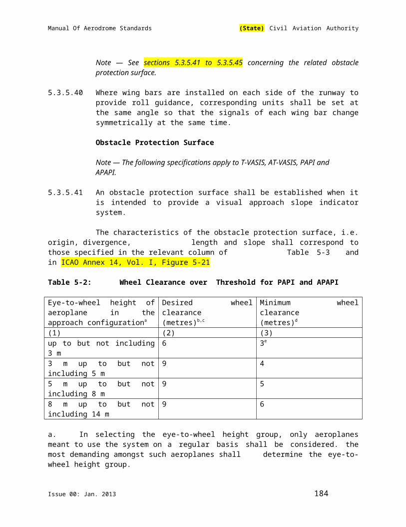
Manual Of Aerodrome Standards (State) Civil Aviation Authority
6.3.10 Recommendation — Where the use of high-intensity obstacle lights, Type A or B, or medium-intensity obstacle lights, Type A, at night may dazzle pilots in the vicinity of an aerodrome (within approximately 10000 m radius) or cause significant environmental concerns, a dual obstacle lighting system should be provided. This system should be composed of high-intensity obstacle lights, Type A or B, as appropriate, for daytime and twilight use and medium-intensity obstacle lights, Type B or C, for night-use.
Location of Obstacle Lights
Note – Recommendations on how a combination of low-, medium-, and/or high-intensity lights on obstacles should be displayed are given in ICAO Annex 14, Vol. I, Appendix 6.
6.3.11 One or more low-, medium-, or high-intensity obstacle lights shall be located as close as practicable to the top of the object. The top light shall be so arranged as to at least indicate the points or edges of the object highest in relation to the obstacle limitation surface.
6.3.12 Recommendation — In the case of chimney or other structure of like function, the top lights should be placed sufficiently below the top so as to minimize contamination by smoke etc. (See ICAO Annex 14, Vol. I, Figures 6-2 and 6-3).
6.3.13 In the case of a tower or antenna structure indicated by high-intensity obstacle lights by day with an appurtenance, such as a rod or antenna, greater than 12 m where it is not practicable to locate a high-intensity obstacle light on the top of the appurtenance, such a light shall be located at the highest practicable point and, if practicable, a medium-intensity obstacle light, Type A, mounted on the top.
6.3.14 In the case of an extensive object or of a group of closely spaced objects, top lights shall be displayed at least on the points or edges of the objects highest in relation to the obstacle limitation surface, so as to indicate the general definition and the extent of the objects. If two or more edges are of the same height, the edge nearest the landing area shall be marked. Where low-intensity lights are used, they shall be spaced at longitudinal intervals not exceeding 45 m. Where medium-intensity lights are used, they shall be spaced at longitudinal intervals not exceeding 900 m.
6.3.15 Recommendation — When the obstacle limitation surface concerned is sloping and the highest point above the obstacle limitation is not the highest point of the object, additional obstacle lights should be placed on the highest point of the object.
6.3.16 Where an object is indicated by medium-intensity obstacle lights, Type A, and the top of the object is more than 105 m above the level of the surrounding ground or the elevation of tops of nearby buildings (when the object to be marked is surrounded by buildings), additional lights shall be provided at intermediate levels. These additional intermediate lights shall be spaced as equally as practicable, between the top lights and ground level or the level of tops of nearby
Issue 00: Jan. 2013 184

Manual Of Aerodrome Standards (State) Civil Aviation Authority
buildings, as appropriate, with the spacing not exceeding 105 m (See section 6.3.7).
6.3.17 Where an object is indicated by medium-intensity obstacle lights, Type B, and the top of the object is more than 45 m above the level of the surrounding ground or the elevation of tops of nearby buildings (when the object to be marked is surrounded by buildings), additional lights shall be provided at intermediate levels. These additional intermediate lights shall be alternately low-intensity obstacle lights, Type B, and medium-intensity obstacle lights, Type B, and shall be spaced as equally as practicable between top lights and ground level or the level of tops of nearby buildings, as appropriate, with the spacing not exceeding 52 m.
6.3.18 Where an object is indicated by medium-intensity obstacle lights, Type C, and the top of the object is more than 45 m above the level of the surrounding ground or the elevation of tops of nearby buildings (when the object to be marked is surrounded by buildings), additional lights shall be provided at intermediate levels. These additional intermediate lights shall be spaced as equally as practicable, between the top lights and ground level or the level of tops of nearby buildings, as appropriate, with the spacing not exceeding 52 m.
6.3.19 Where high-intensity obstacle lights, Type A, are used, they shall be spaced at uniform intervals not exceeding 105 m between the ground level and the top light(s) specified in section 6.3.11 except that where an object to be marked is surrounded by buildings, the elevation of the tops of the buildings may be used as the equivalent of the ground level when determining the number of light levels.
6.3.20 Where high-intensity obstacle lights, Type B, are used, they shall be located at three levels:
- at the top of the tower;
- at the lowest level of the catenary of the wires or cables; and
- at approximately midway between these two levels.
Note – In some cases, this may require locating of the lights off the tower.
6.3.21 Recommendation — The installation setting angles for high-intensity obstacle lights, Type A and B, should be in accordance with Table 6-2.
6.3.22 The number and arrangement of low-, medium- or high-intensity obstacle lights at each level to be marked shall be such that the object is indicated from every angle in azimuth. Where a light is shielded in any direction by another part of the object, or by an adjacent object, additional lights shall be provided on that object in such a way as to retain the general definition of the object to be lighted. If the shielded light does not contribute to the definition of the object to be lighted, it may be omitted.
Table 6-2 – Installation Setting Angles for High-Intensity Obstacle Lights
Issue 00: Jan. 2013 185
Manual Of Aerodrome Standards (State) Civil Aviation Authority
Height of light limit above terrain
Angle of the peak of the beam above horizontal
greater than 151m AGL 0o
122m to 151m AGL 1o
92m to 122m AGL 2o
less than 92m AGL 3o
Low-Intensity Obstacle Lights – Characteristics
6.3.23 Low-intensity obstacle lights on fixed objects, Types A and B, shall be fixed- red lights.
6.3.24 Low-intensity obstacle lights, Type A and B, shall be in accordance with the specifications in Table 6-3.
6.3.25 Low-intensity obstacle lights, Type C, displayed on vehicles associated with emergency or security shall be flashing-blue and those displayed on other vehicles shall be flashing-yellow.
6.3.26 Low-intensity obstacle lights, Type D, displayed on follow-me vehicles shall be flashing-yellow.
6.3.27 Low-intensity obstacle lights, Types C and D, shall be in accordance with the specifications in Table 6-3.
6.3.28 Low-intensity obstacle lights on objects with limited mobility such as aerobridges shall be fixed-red. The intensity of the lights shall be sufficient to ensure conspicuity considering the intensity of the adjacent lights and the general levels of illumination against which they would normally be viewed.
Note – See ICAO Annex 2 for lights to be displayed by aircraft.
6.3.29 Low-intensity obstacle lights on objects with limited mobility shall as a minimum be in accordance with the specifications for low-intensity obstacle lights, Type A, in Table 6-3.
Medium-Intensity Obstacle Light – Characteristics
6.3.30 Medium-intensity obstacle lights, Type A, shall be flashing-white lights, Type B shall be flashing-red lights and Type C shall be fixed-red lights.
6.3.31 Medium-intensity obstacle lights, Type A,B and C, shall be in accordance with the specifications in Table 6-3.
6.3.32 Medium-intensity obstacle lights, Type A and B, located on an object shall flash simultaneously.
High-Intensity Obstacle Light – Characteristics
Issue 00: Jan. 2013 186

Manual Of Aerodrome Standards (State) Civil Aviation Authority
6.3.33 High-intensity obstacle lights, Types A and B, shall be flashing-white lights.
6.3.34 High-intensity obstacle lights, Types A and B, shall be in accordance with the specifications in Table 6-3.
6.3.35 High-intensity obstacle lights, Type A, located on an object shall flash simultaneously.
6.3.36 Recommendation - High-intensity obstacle lights, Type B, indicating the presence of a tower supporting overhead wires, cables, etc., should flash sequentially; first the middle light, second the top light and last, the bottom light. The intervals between flashes of the lights should approximate the following ratios:
Flash interval between Ratio of cycle
middle and top light 1/13
top and bottom light 2/13
bottom and middle light 10/13
Table 6.3 Characteristics of Obstacle Lights1 2 3 4 5 6 7 8 9 10 11 12
Light Type Colour
Signal Type/(flash rate)
Peak intensity (cd) at given background luminance
Vertical beam spread(c)
Intensity (cd) at given Elevation Angles when the light unit is levelled (d)
Above 500 cd/m2
50-500 cd/m2
Below 50 cd/m2
-10° (e)
-1° (f)
±0° (f)
+6° +10°
Low-intensity, Type A (fixed obstacle)
Red Fixed N/A 10 mnm
10 mnm
10° ─ ─ ─ 10 mnm (g)
10 mnm (g)
Low-intensity, Type B (fixed obstacle)
Red Fixed N/A 32 mnm
32 mnm
10° ─ ─ ─ 32 mnm (g)
32 mnm (g)
Low-intensity, Type C(mobile obstacle)
Yellow/blue(a)
Flashing(60-90 fpm)
N/A 40 mnm (b)400 max
40 mnm (b)400 max
12° (h) ─ ─ ─ ─ ─
Low-intensity, Type DFollow-me
Yellow Flashing(60-90 fpm)
N/A 200 mnm (b)400
200 mnm (b)400
12° (i) ─ ─ ─ ─ ─
Issue 00: Jan. 2013 187

Manual Of Aerodrome Standards (State) Civil Aviation Authority
Vehicle max maxMedium-intensity, Type A
White Flashing(20-60 fpm)
20 000 (b)±25%
20 000 (b)±25%
2 000 (b)±25%
3° mnm
3% max
50% mnm75% max
100% mnm
─ ─
Medium-intensity, Type B
Red Flashing(20-60 fpm)
N/A N/A 2 000 (b)±25%
3° mnm
─ 50% mnm75% max
100% mnm
─ ─
Medium-intensity, Type C
Red fixed N/A N/A 2 000 (b)±25%
3° mnm
─ 50% mnm75% max
100% mnm
─ ─
High-intensity, Type A
White Flashing(40-60 fpm)
200000 (b)±25%
20000 (b)±25%
2000 (b)±25%
3° - 7° 3% max
50% mnm75% max
100% mnm
─ ─
High-intensity, Type B
White Flashing(40-60 fpm)
100000 (b)±25%
20000 (b)±25%
2000 (b)±25%
3° - 7° 3% max
50% mnm75% max
100% mnm
─ ─
Note. ─ This table does not include recommended horizontal beam spreads. Section 6.3.22 requires 360° coverage around an obstacle. Therefore, the number of lights needed to meet this requirement will depend on the horizontal beam spreads of each light as well as the shape of the obstacle. Thus, with narrower beam spreads, more lights will be required.
(a) See section 6.3.25(b) Effective intensity, as determined in accordance with the Aerodrome Design
Manual(Doc 9157), Part 4.(c) Beam spread is defined as the angle between two directions in a plane for which the
intensity is equal to 50% of the lower tolerance value of the intensity shown in columns 4, 5 and 6. The beam pattern is not necessarily symmetrical about the elevation angle at which the peak intensity occurs.
(d) Elevation (vertical) angles are referenced to the horizontal.(e) Intensity at any specified horizontal radial as a percentage of the actual peak
intensity at the same radial when operated at each of the intensities shown in columns 4, 5 and 6.
(f) Intensity at any specified horizontal radial as a percentage of the lower tolerance value of the intensity shown in columns 4, 5 and 6
(g) In addition to specified values, lights shall have sufficient intensity to ensure conspicuity at elevation angles between ±0° and ±50°.
(h)Peak intensity should be located at approximately 2.5° vertical.(i) Peak intensity should be located at approximately 2.5° vertical.
Issue 00: Jan. 2013 188

Manual Of Aerodrome Standards (State) Civil Aviation Authority
Fpm ─ flashes per minute; N/A ─ not applicable
6.4 Wind turbines
6.4.1 A wind turbine shall be marked and/or lighted if it is determined to be an obstacle.
Note.— See 4.3.1 and 4.3.2.
Markings
6.4.2 Recommendation.— The rotor blades, nacelle and upper 2/3 of the supporting mast of wind turbines should be painted white, unless otherwise indicated by an aeronautical study.
Lighting
6.4.3 Recommendation.— When lighting is deemed necessary, medium-intensity obstacle lights should be used. In the case of a wind farm, i.e. a group of two or more wind turbines, it should be regarded as an extensive object and the lights should be installed:
(a) to identify the perimeter of the wind farm;
(b) respecting the maximum spacing, in accordance with 6.3.14, between the lights along the perimeter, unless a dedicated assessment shows that a greater spacing can be used;
(c) so that, where flashing lights are used, they flash simultaneously; and
(d) so that, within a wind farm, any wind turbines of significantly higher elevation are also identified wherever they are located.
6.4.4 Recommendation.— The obstacle lights should be installed on the nacelle in such a manner as to provide an unobstructed view for aircraft approaching from any direction.
Issue 00: Jan. 2013 189

Manual Of Aerodrome Standards (State) Civil Aviation Authority
CHAPTER 7. VISUAL AIDS FOR DENOTING RESTRICTED USE AREA
7.1 Closed Runways and Taxiways, or Parts Thereof
Application
Permanently Closed Runway or Taxiway
7.1.1 A closed marking shall be displayed on a runway or taxiway, or portion thereof, which is permanently closed to the use of all aircraft.
Note – See also section 7.4 for application of unserviceability markers and lights.
Temporarily Closed Runway or Taxiway
7.1.2. Recommendation – A closed marking should be displayed on a temporarily closed runway or taxiway or portion thereof, except that such marking may be omitted when the closing is of short duration (less than 3 days) and adequate warning by air traffic services is provided.
Note – See also section 7.4 for application of unserviceability markers and lights.
Location
7.1.3 On a runway, a closed marking shall be placed at each end of the runway or portion thereof, declared closed, and additional markings shall be so placed that the maximum interval between markings does not exceed 300m. On a taxiway a closed marking shall be placed at least at each end of the taxiway or portion thereof closed.
Characteristics
7.1.4 The closed marking shall be of the form and proportions as detailed in ICAO Annex 14, Vol. I, Figure 7-1, Illustration a), when displayed on a runway, and shall be of the form and proportions as detailed in ICAO Annex 14, Vol. I, Figure 7-1, Illustration b), when displayed on a taxiway. The marking shall be white when displayed on a runway and shall be yellow when displayed on a taxiway.
Issue 00: Jan. 2013 190

Manual Of Aerodrome Standards (State) Civil Aviation Authority
Note – When an area is temporarily closed, frangible barriers or markings utilizing materials other than paint or other suitable means may be used to identify the closed area.
7.1.5 When a runway or taxiway or portion thereof is permanently closed, all normal runway and taxiway markings shall be obliterated.
7.1.6 Lighting on a closed runway or taxiway or portion thereof shall not be operated, except as required for maintenance purposes.
7.1.7 In addition to closed markings, when the runway or taxiway or portion thereof closed is intercepted by a usable runway or taxiway which is used at night, unserviceability lights shall be placed across the entrance to the closed area at intervals not exceeding 3m (See section 7.4.4).
7.2 Non-Load-Bearing Surfaces
Application
7.2.1 Shoulders for taxiways, runway turn pads, holding bays and aprons and other non-Load-bearing surfaces, which cannot readily be distinguished from load-bearing surfaces and which, if used by aircraft, might result in damage to the aircraft shall have the boundary between such areas and the load-bearing surface marked by a taxi side stripe marking.
Note – The marking of runway sides is specified in section 5.2.7
Location
7.2.2 A taxi side stripe marking shall be placed along the edge of the load-bearing pavement, with the outer edge of the marking approximately on the edge of the load-bearing pavement.
Characteristics
7.2.3 A taxi side stripe marking shall consist of a pair of solid lines, each 15cm wide and spaced 15cm apart and the same colour as the taxiway centre line marking.
Note – Guidance on providing additional transverse stripes at an intersection or a small area on the apron is given in the ICAO Aerodrome Design Manual(Doc 9157) Part 4.
7.3 Pre-Threshold Area
Application
7.3.1 When the surface before a threshold is paved and exceeds 60m in length and is not suitable for normal use by aircraft, the entire length before the threshold shal be marked with a chevron marking.
Issue 00: Jan. 2013 191
Manual Of Aerodrome Standards (State) Civil Aviation Authority
Location
7.3.2 A chevron marking shall point in the direction of the runway and be placed as shown in ICAO Annex 14, Vol. I, Figure 7-2
Characteristics
7.3.3 A chevron marking shall be of conspicuous colour and contrast with the colour used for the runway markings; it should preferably be yellow. It should have an over-all width of at least 0.9m.
7.4 Unserviceable Areas
Application
7.4.1 Unserviceability markers shall be displayed wherever any portion of a taxiway, apron or holding bay is unfit for the movement of aircraft but it is still possible for aircraft to bypass the area safely. Unserviceability markers shall also be displayed at the entrances to a permanently or temporarily closed runway or taxiway, or part thereof. On a movement area used at night, unserviceability lights shall be used.
Note – Unserviceability markers and lights are used to guide aircraft to bypass a portion of a taxiway, apron or holding bay that is unfit for normal movement are intended for such purposes as warning pilots of a hole in a taxiway or apron pavement or outlining a portion of pavement, such as on an apron, that is under repair. They are not suitable for use when a portion of a runway becomes unserviceable, nor on a taxiway when a major portion of the width becomes unserviceable. In such instances, the runway or taxiway is normally closed.
Location
7.4.2 Unserviceability markers and lights shall be placed at intervals sufficiently close so as to delineate the unserviceable area.
Note – Guidance on the location of unserviceability lights is given in Attachment A, Section 13.
Characteristics of Unserviceable Markers
7.4.3 Unserviceability markers shall consist of conspicuous upstanding devices such as flags, cones or marker boards.
Characteristics of Unserviceability Lights
7.4.4 An unserviceability light shall consist of a red fixed light. The light shall have an intensity sufficient to ensure conspicuity considering the intensity of the adjacent
Issue 00: Jan. 2013 192
Manual Of Aerodrome Standards (State) Civil Aviation Authority
lights and the general level of illumination against which it would normally be viewed. In no case shall the intensity be less than 10 cd of red light.
Characteristics of Unserviceability Cones
7.4.5 Recommendation – An unserviceability cone should be at least 0.5m in height and red, orange or yellow or any one of these colours in combination with white.
Characteristics of Unserviceability Flags
7.4.6 Recommendation – An unserviceability flag should be at least 0.5m square and red, orange or yellow or any one of these colours in combination with white.
Characteristics of Unserviceability Marker Boards
7.4.7 Recommendation – An unserviceable marker board should be at least 0.5m in height and 0.9m in length, with alternate red and white or orange and white vertical stripes.
Issue 00: Jan. 2013 193

Manual Of Aerodrome Standards (State) Civil Aviation Authority
CHAPTER 8. ELECTRICAL SYSTEMS
Electrical Power Supply Systems For Air Navigation Facilities
Introductory Note.— The safety of operations at aerodromes depends on the quality of the supplied power. The total electrical power supply system may include connections to one or more external sources of electric power supply, one or more local generating facilities and to a distribution network including transformers and switchgear. Many other aerodrome facilities supplied from the same system need to be taken into account while planning the electrical power system at aerodromes.
8.1 Primary Power Supply
8.1.1 Adequate primary power supply shall be available at aerodromes for the safe functioning of air navigation facilities.
8.1.2 The design and provision of electrical power systems for aerodrome visual and radio navigation aids shall be such that an equipment failure will not leave the pilot with inadequate visual and non-visual guidance or misleading information.
Note : The design and installation of the electrical systems need to take into consideration factors that can lead to malfunction, such as electromagnetic disturbances, line losses, power quality, etc. Additional guidance is given in the Aerodrome Design Manual(Doc 9157), Part 5.
8.1.3 Electric power supply connections to those facilities for which secondary power is required shall be so arranged that the facilities are automatically connected to the secondary power supply on failure of the primary source of power.
Issue 00: Jan. 2013 194

Manual Of Aerodrome Standards (State) Civil Aviation Authority
8.1.4 The time interval between failure of primary source of power and the complete restoration of the services required by section 8.1.10 shall be as short as practicable, except that for visual aids associated with non – precision, precision approach or take – off runways the requirements of Table 12-1 for maximum switch-over times should apply.
Note : A definition of switch-over time is given in Chapter 1.
8.1.5 The provision of a definition of switch-over time shall not require the replacement of an existing secondary power supply before 1st January 2010. However, for a secondary power supply installed after 4th November 1999, the electric power supply connections to those facilities for which secondary power is required shall be so arranged that the facilities are capable of meeting the requirements of Table 12-1 for maximum switch-over times as defined in Chapter 1
Table 8-1 - Secondary Power Supply Requirements (See section 8.1.4)
Runway Lighting aids requiring power Maximumswitchover time
Non-instrument Visual approach slope indicatorsa Runway edgeb
Runway thresholdb
Runway endb
Obstaclea
See sections8.1.4 and8.1.9
Non-Precision approach Approach lighting systemVisual approach slope indicatorsa,d
Runway edged
Runway thresholdd
Runway endObstaclea
15 seconds15 seconds15 seconds15 seconds15 seconds15 seconds
Precision approachcategory I
Approach lighting systemRunway edged
Visual approach slope indicatorsa,d
Runway thresholdd
Runway endEssential taxiwaya
Obstaclea
15 seconds15 seconds15 seconds15 seconds15 seconds15 seconds15 seconds
Precision approachcategory II/III
Inner 300m of the Approach lighting system Other parts of the approach lighting systemObstaclea
Runway edgeRunway thresholdRunway end
1 seconds15 seconds15 seconds15 seconds1 second1 second1 second1 second
Issue 00: Jan. 2013 195

Manual Of Aerodrome Standards (State) Civil Aviation Authority
Runway centre lineRunway touchdown zoneAll stop bars Essential taxiway
1 second15 seconds
Runway meant for takeoff in runway visual range conditions less than a value of 800 m.
Runway edgeRunway endRunway centre lineAll stop bars Essential taxiwaya
Obstaclea
15 secondsc
1 second1 second1 second15 seconds15 seconds
Supplied with secondary power when their operation is essential to the safety of flight operation.See, 5.3.2 of this Manual regarding the use of emergency lighting.One second where no runway centre line lights are provided.One second where approaches are over hazardous or precipitous terrain.
Visual aids
Application
8.1.6 For a precision approach runway, a secondary power supply capable of meeting the requirements of Table 8-1 for the appropriate category of precision approach runway shall be provided. Electric power supply connections to those facilities for which secondary power is required shall be so arranged that the facilities are automatically connected to the secondary power supply on failure of the primary source of power.
8.1.7 For a runway meant for take-off in runway visual range conditions less than a value of 800 m, a secondary power supply capable of meeting the relevant requirements of Table 8-1 shall be provided.
8.1.8 At an aerodrome where the primary runway is a non-precision approach runway,
a secondary power supply capable of meeting the requirements of Table 8-1 shall be provided except that a secondary power supply for visual aids need not be provided for more than one non-precision approach runway.
8.1.9 At an aerodrome where the primary runway is a non-instrument runway, a secondary power supply capable of meeting the requirements of section 8.1.4 shall be provided, except that a secondary power supply for visual aids need not be provided when an emergency lighting system in accordance with the specification of section 5.3.2 is provided and capable of being deployed in 15 minutes.
8.1.10 The following aerodrome facilities shall be provided with a secondary power supply capable of supplying power when there is a failure of the primary power supply:
Issue 00: Jan. 2013 196
Manual Of Aerodrome Standards (State) Civil Aviation Authority
(a) the signalling lamp and the minimum lighting necessary to enable air traffic services personnel to carry out their duties;
Note — The requirement for minimum lighting may be met by other than electrical means.
(b) all obstacle lights which, in the opinion of the Authority , are essential to ensure the safe operation of aircraft;
(c) approach, runway and taxiway lighting as specified in sections 8.1.6 to 8.1.9;
(d) meteorological equipment;
(e) essential security lighting, if provided in accordance with Section 9.11;
(f) essential equipment and facilities for the aerodrome responding emergency agencies;
(g) floodlighting on a designated isolated aircraft parking position ifprovided in accordance with section 5.3.23.1; and
(h) illumination of apron areas over which passengers may walk.
Note.— Specifications for secondary power supply for radio navigation aids and ground elements of communications systems are given in ICAO Annex 10, Volume I, Chapter 2.
8.1.11 Requirements for a secondary power supply shall be met by either of the following:
— independent public power, which is a source of power supplying the
aerodrome service from a substation other than the normal substation through a transmission line following a route different from the normal power supply route and such that the possibility of a simultaneous failure of the normal and independent public power supplies is extremely remote; or
— standby power unit(s), which are engine generators, batteries, etc., from which electric power can be obtained.
Note — Guidance on secondary power supply is given in the ICAO Aerodrome Design Manual(Doc 9157), Part 5— Electrical Systems.
8.2 System Design
8.2.1 For a runway meant for use in runway visual range conditions less than a value of 550 m, the electrical systems for the power supply, lighting and control of the
Issue 00: Jan. 2013 197

Manual Of Aerodrome Standards (State) Civil Aviation Authority
lighting systems included in Table 8-1 shall be so designed that an equipment failure will not leave the pilot with inadequate visual guidance or misleading information.
Note — Guidance on means of providing this protection is given in the ICAO Aerodrome Design Manual(Doc 9157), Part 5 — Electrical Systems.
8.2.2 Where the secondary power supply of an aerodrome is provided by the use of duplicate feeders, such supplies shall be physically and electrically separated so as to ensure the required level of availability and independence.
8.2.3 Where a runway forming part of a standard taxi-route is provided with runway
lighting and taxiway lighting, the lighting systems shall be interlocked to preclude the possibility of simultaneous operation of both forms of lighting.
8.3 Monitoring
Note — Guidance on this subject is given in the ICAO Aerodrome Design Manual(Doc 9157), Part 5— Electrical Systems.
8.3.1 A system of monitoring shall be employed to indicate the operational status of the lighting systems.
8.3.2 Where lighting systems are used for aircraft control purposes, such systems shall be monitored automatically so as to provide an indication of any fault which may affect the control functions. This information shall be automatically relayed to the air traffic services unit.
8.3.3 Recommendation.— Where a change in the operational status of lights has occurred, an indication should be provided within two seconds for a stop bar at a runway holding position and within five seconds for all other types of visual aids.
8.3.4 Recommendation — For a runway meant for use in runway visual range conditions less than a value of 550 m, the lighting systems detailed in Table 8-1 should be monitored automatically so as to provide an indication when the serviceability level of any element falls below the minimum serviceability level specified in sections 10.4.7 to 10.4.11 as appropriate. This information should be immediately relayed to the maintenance crew.
8.3.5 Recommendation — For a runway meant for use in runway visual range conditions less than a value of 550 m, the lighting systems detailed in Table 8-1 of this Manual should be monitored automatically to provide an indication when the serviceability level of any element falls below the minimum level specified by the appropriate authority below which operations should not continue. This information should be automatically relayed to the air traffic services unit and displayed in a prominent position.
Issue 00: Jan. 2013 198
Manual Of Aerodrome Standards (State) Civil Aviation Authority
Note — Guidance on air traffic control interface and visual aids monitoring is included in the ICAO Aerodrome Design Manual(D0c 9457), Part 5 — Electrical Systems.
CHAPTER 9. AERODROME OPERATIONAL SERVICES, EQUIPMENT AND INSTALLATIONS
9.1 Aerodrome Emergency Planning
Note — Additional standards on Aerodrome Emergency Planning are provided in Part III Chapter 1
General
Aerodrome emergency planning is the process of preparing an aerodrome to cope with an emergency occurring at the aerodrome or in its vicinity. The objective of aerodrome emergency planning is to minimize the effects of an emergency, particularly in respect of saving lives and maintaining aircraft operations. The aerodrome emergency plan sets forth the procedures for coordinating the response of different aerodrome agencies (or services) and of those agencies in the surrounding community that could be of assistance in responding to the emergency. Additional Standards on Aerodrome Emergency Plan are contained in Part III. Guidance material to assist the aerodrome operator in establishing aerodrome emergency planning is given in the ICAO Airport Services Manual(Doc 9137), Part 7.
9.1.1 An aerodrome emergency plan shall be established at an aerodrome, commensurate with the aircraft operations and other activities conducted at the aerodrome.
Issue 00: Jan. 2013 199

Manual Of Aerodrome Standards (State) Civil Aviation Authority
9.1.2 The aerodrome emergency plan shall provide for the coordination of the actions to be taken in an emergency occurring at an aerodrome or in its vicinity.
Note 1. —Example of emergencies: Aircraft emergencies, sabotage including bomb treats, unlawfully seized aircraft, dangerous goods occurrences, building fires, natural disasters, public health emergencies and fires on the ground
Note 2.— Examples of public health emergencies are increased risk of travellers or cargo spreading a serious communicable disease internationally through air transport and severe outbreak of a communicable disease potentially affecting a large proportion of aerodrome staff.
9.1.3 The plan shall coordinate the response or participation of all existing agencies which, in the opinion of the Authority could be of assistance in responding to an emergency.
Note 1 — Examples of agencies are:
- on the aerodrome: air traffic control unit, rescue and fire fighting services, aerodrome administration, medical and ambulance services, aircraft operators, security services, and police;
- off the aerodrome: fire departments, police, medical and ambulance services, hospitals, military, and harbour patrol or coast guard.
Note 2.— Public health services include planning to minimize adverse effects to the community from health-related events and deal with population health issues rather than provision of health services to individuals.
9.1.4 The plan shall provide for cooperation and coordination with the rescue coordination centre as necessary.
9.1.5 Left Blank Intentionally
Note — Part III section 1.1 contain standards on the content of the Aerodrome Emergency Plan.
9.1.6 The plan shall observe Human Factors principles to ensure optimum response by all existing agencies participating in emergency operations.
Note — Guidance material on Human Factors principles can be found in ICAOHuman Factors Training Manual(Doc 9683).
Emergency Operations Centre and Command Post
9.1.7 An Emergency Operations Centre and a mobile command post shall be available for use during an emergency.
Issue 00: Jan. 2013 200

Manual Of Aerodrome Standards (State) Civil Aviation Authority
9.1.8 The Emergency Operations Centre shall be a part of the aerodrome facilities and shall be responsible for the overall coordination and general direction of the response to an emergency.
9.1.9 The command post shall be a facility capable of being moved rapidly to the site of an emergency, when required, and shall undertake the local coordination of those agencies responding to the emergency.
9.1.10 A person shall be assigned to assume control of the Emergency Operations Centre and, when appropriate, another person the mobile command post.
Communication System
9.1.11 Adequate communication systems linking the command post and the Emergency Operations Centre with each other and with the participating agencies shall be provided in accordance with the plan and consistent with the particular requirements of the aerodrome.
Aerodrome Emergency Exercise
Note — Standards on Aerodrome Emergency Exercise is in Part III section 1.15
9.1.12 Left Blank Intentionally
9.1.13 Left Blank Intentionally .
Emergencies in Difficult Environments
9.1.14 The plan shall include the ready availability of and coordination with appropriate specialist rescue services to be able to respond to emergencies where an aerodrome is located close to water and/swampy areas and where a significant portion of approach or departure operations takes place over these areas.
9.1.15 Recommendation — At those aerodromes located close to water and/or swampy areas, or difficult terrain, the aerodrome emergency plan should include the establishment, testing and assessment at regular intervals of a predetermined response for the specialist rescue services.
9.2 Rescue and Fire Fighting
General
The principal objective of a rescue and fire fighting service is to save lives. For this reason, the provision of means of dealing with an aircraft accident or incident occurring at, or in the immediate vicinity of, an aerodrome assumes primary importance because it is within this area that there are the greatest opportunities of saving lives. This must assume at all times the possibility of, and need for, extinguishing a fire which may occur either immediately following an aircraft
Issue 00: Jan. 2013 201
Manual Of Aerodrome Standards (State) Civil Aviation Authority
accident or incident, or at any time during rescue operations. The most important factors bearing on effective rescue in a survivable aircraft accident are: the training received, the effectiveness of the equipment and the speed with which personnel and equipment designated for rescue and fire fighting purposes can be put into use. Requirements to combat building and fuel farm fires are dealt with under separate emergency procedures.
Application
9.2.1 Rescue and fire fighting equipment and services shall be provided at an aerodrome.
Note — Public or private organisations, suitably located and equipped, may be designated to provide the rescue and fire fighting service. It is intended that the fire station housing these organisations be normally located on the aerodrome, although an off-aerodrome location is not precluded provided the response time can be met.
9.2.2 Where an aerodrome is located close to water/swampy areas or difficult terrain, and where a significant portion of approach or departure operations takes place over these areas, specialist rescue services and fire fighting equipment appropriate to the hazard and risk shall be available.
Note 1 — Special fire fighting equipment need not be provided for water areas; this does not prevent the provision of such equipment if it would be of practical use, such as when the areas concerned include reefs or islands.
Note 2 — The objective is to plan and deploy the necessary life-saving flotation equipment as expeditiously as possible in a number commensurate with the largest aeroplane normally using the aerodrome.
Note 3 — Additional guidance is available in Chapter 13 of the ICAO Airport Services Manual(Doc 9137), Part 1.
Level of Protection to be Provided
9.2.3 The level of protection provided at an aerodrome for rescue and fire fighting shall be appropriate to the aerodrome category determined using the principles in sections 9.2.5 and 9.2.6, except that, where the number of movements of the aeroplanes in the highest category normally using the aerodrome is less than 700 in the busiest consecutive three months, the level of protection provided shall be not less than one category below the determined category.
Note — Either a take-off or landing constitutes a movement.
9.2.4 The level of protection provided at an aerodrome for rescue and fire fighting shall be equal to the aerodrome category determined using the principles
in sections 9.2.5 and 9.2.6.
Issue 00: Jan. 2013 202
Manual Of Aerodrome Standards (State) Civil Aviation Authority
9.2.5 The aerodrome category shall be determined from Table 9-1 of this Manual and shall be based on the longest aeroplanes normally using the aerodrome and their fuselage width.
Note — To categorize the aeroplanes using the aerodrome, first evaluate their overall length and second, their fuselage width.
9.2.6 If, after selecting the category appropriate to the longest aeroplane’s overall length, that aeroplane’s fuselage width is greater than the maximum width in Table 9-1, column 3 for that category, then the category for that aeroplane shall actually be one category higher.
Note 1.— See guidance in the Airport Services Manual (Doc 9137), Part 1, for categorizing aerodromes, including those for all-cargo aircraft operations, for rescue and fire fighting purposes.
Note 2.— Guidance on training of personnel, rescue equipment for difficult environments and other facilities and services for rescue and fire fighting is given in Attachment A, Section 17, and in the Airport Services Manual (Doc 9137), Part 1.
Table 13-1 - Aerodrome Category for Rescue and Fire Fighting
Aerodrome Category Aeroplane overall length Maximum fuselage width(1) (2) (3)1 0 m up to but not including 9 m 2m2 9 m up to but not including 12 m 2m3 12 m up to but not including 18 m 3m4 18 m up to but not including 24 m 4m5 24 m up to but not including 28 m 4m6 28 m up to but not including 39 m 5m7 39 m up to but not including 49 m 5m8 49 m up to but not including 61 m 7m9 61 m up to but not including 76 m 7m10 76 m up to but not including 90 m 8m
9.2.7. During anticipated periods of reduced activity, the level of protection available shall be no less than that needed for the highest category of aeroplane planned to use the aerodrome during that time irrespective of the number of movements.
Extinguishing Agents
9.2.8 Both principal and complementary agents shall be provided at an aerodrome.
Note — Descriptions of the agents may be found in the ICAO Airport Services Manual(Doc 9137), Part 1.
9.2.9 The principal extinguishing agents shall be:
Issue 00: Jan. 2013 203

Manual Of Aerodrome Standards (State) Civil Aviation Authority
(a) a foam meeting the minimum performance level A; or
(b) a foam meeting the minimum performance level B; or
(c) a combination of these agents;
except that the principal extinguishing agent for aerodromes in categories 1 to 3 shall preferably meet the minimum performance level B.
Note — Information on the required physical properties and fire extinguishing performance criteria needed for a foam to achieve an acceptable performance level A or B rating is given in the ICAO Airport Services Manual(Doc 9137), Part 1.
9.2.10 The complementary extinguishing agent shall be a dry chemical powder suitable for extinguishing hydrocarbon fires.
Note 1 — When selecting dry chemical powders for use with foam, care must beexercised to ensure compatibility.
Note 2 — Alternate complementary agents having equivalent fire fighting capability may be utilized. Additional information on extinguishing agents is given in the ICAO Airport Services Manual(Doc 9137), Part 1.
9.2.11 The amounts of water for foam production and the complementary agents to be provided on the rescue and fire fighting vehicles shall be in accordance with the aerodrome category determined under sections 9.2.3, 9.2.4, 9.2.5, 9.2.6 and Table 9-2 of this Manual, except that these amounts may be modified as follows:
(a) for aerodrome categories 1 and 2 up to 100 per cent of the water may be
replaced by complementary agent; or
(b) for aerodrome categories 3 to 10 when a foam meeting performance level A is used, up to 30 per cent of the water may be replaced by complementary agent.
For the purpose of agent substitution, the following equivalents shall be used:
1 kg complementary = 1.0 L of water for production of a foamagent meeting performance level A
1 kg complementary = 0.66 L of water for production of aagent foam meeting performance level B
Note 1 — The amounts of water specified for foam production are predicated on an application rate of 8.2 L/min/m2 for a foam meeting performance level A, and 5.5 L/min/m2 for a foam meeting performance level B.
Note 2 – When any other complementary agent is used, the substitution ratios need to be checked.
Issue 00: Jan. 2013 204

Manual Of Aerodrome Standards (State) Civil Aviation Authority
9.2.12 Recommendation.— At aerodromes where operations by aeroplanes larger than the average size in a given category are planned, the quantities of water should be recalculated and the amount of water for foam production and the discharge rates for foam solution should be increased accordingly.
Note.— Additional guidance is available in Chapter 2 of the Airport Services Manual (Doc 9137), Part 1.
9.2.13 The quantity of foam concentrates separately provided on vehicles for foam production shall be in proportion to the quantity of water provided and the foam concentrate selected.
9.2.14 Recommendation — The amount of foam concentrate provided on a vehicle
should be sufficient to produce at least two loads of foam solution.
9.2.15 Recommendation — Supplementary water supplies, for the expeditious replenishment of rescue and fire fighting vehicles at the scene of an aircraft accident, shall be provided.
9.2.16 Recommendation — When both a foam meeting performance level A and a foam meeting performance level B are to be used, the total amount of water to be provided for foam production should first be based on the quantity which would be required if only a foam meeting performance level A were used, and then reduced by 3L for each 2L of water provided for the foam meeting performance level B.
9.2.17 The discharge rate of the foam solution shall not be less than the rates shown in Table 9-2.
9.2.18 The complementary agents shall comply with the appropriate specifications of
the International Organisation for Standardisation (ISO).*
9.2.19 The discharge rate of complementary agents shall be not less than the value shown in Table 9-2.
9.2.20 Recommendation.— Dry chemical powders should only be substituted with an agent that has equivalent or better fire fighting capabilities for all types of fires where complementary agent is expected to be used.
Note.— Guidance on the use of complementary agents can be found in the Airport Services Manual (Doc 9137), Part 1.
9.2.21 A reserve supply of foam concentrate and complementary agent, equivalent to 200 per cent of the quantities of these agents to be provided in the rescue and fire fighting vehicles, shall be maintained on the aerodrome for vehicle replenishment purposes. Where a major delay in the replenishment of this supply is anticipated, the amount of reserve supply shall be increased.
Rescue Equipment
Issue 00: Jan. 2013 205
Manual Of Aerodrome Standards (State) Civil Aviation Authority
9.2.22 Recommendation — Rescue equipment commensurate with the level of aircraft operations should be provided on the rescue and fire fighting vehicle(s).
Note — Guidance on the rescue equipment to be provided at an aerodrome is
given in the ICAO Airport Services Manual(Doc 9137), Part 1.
Response Time
9.2.23 The operational objective of the rescue and fire fighting service shall be to achieve a response time not exceeding three minutes, to any point of each operational runway, in optimum visibility and surface conditions.
* See ISO Publication 7202(Powder). Table 9-2 - Minimum Usable Amounts of Extinguishing Agents
Foam meeting performance level A
Foam meeting performance level B
Complementary Agents
Aerodrome Category
Water (L)
Discharge rate foam solution/minute (L)
Water (L)
Discharge rate foam solution/minute (L)
Dry chemical powder (kg)
DischargeRateKg/sec
(1) (2) (3) (4) (5) (6) (7)1 350 350 230 230 45 2.252 1 000 800 670 550 90 2.253 1 800 1 300 1 200 900 135 2.254 3 600 2 600 2 400 1 800 135 2.255 8 100 4 500 5 400 3 000 180 2.256 11 800 6 000 7 900 4 000 225 2.257 18 200 7 900 12 100 5 300 225 2.258 27 300 10 800 18 200 7 200 450 4.59 36 400 13 500 24 300 9 000 450 4.510 48 200 16 600 32 300 11 200 450 4.5
Note 1 — The quantities of water shown in columns 2 and 4 are based on the average overall length of aeroplanes in a given category.
9.2.24 Recommendation — The operational objective of the rescue and fire fighting service should be to achieve a response time not exceeding two minutes to any point of each operational runway, in optimum visibility and surface conditions.
.9.2.25 Recommendation — The operational objective of the rescue and fire fighting
service should be to achieve a response time not exceeding three minutes, to any other part of the movement area in optimum visibility and surface conditions.
Note 1 — Response time is considered to be the time between the initial call to
Issue 00: Jan. 2013 206

Manual Of Aerodrome Standards (State) Civil Aviation Authority
the rescue and fire fighting service, and the time when the first responding vehicle(s) is (are) in position to apply foam at a rate of at least 50 per cent of the discharge rate specified in Table 9-2.
Note 2 — Optimum visibility and surface conditions are defined as daytime, good visibility, no precipitation with normal response route free of surface contamination e.g. water.
Note 3 — Additional Standards on the conduct of response test is in Part III Section 2.9.2
9.2.26 Recommendation.— To meet the operational objective as nearly as possible in less than optimum conditions of visibility, especially during low visibility operations, suitable guidance, equipment and/or procedures for rescue and fire fighting services should be provided.
Note.— Additional guidance is available in the Airport Services Manual (Doc 9137), Part 1.
9.2.27 Any vehicles other than the first responding vehicle(s) required to deliver the amounts of extinguishing agents specified in Table 9-2 shall ensure continous agent application and shall arrive no more than three minutes from the initial call.
9.2.28 Recommendation.— Any vehicles, other than the first responding vehicles(s), required to deliver the amounts of extinguishing agents specified in Table 9-2 should ensure continuous agent application and should arrive no more than three minutes from the initial call.
9.2.29 A system of preventive maintenance of rescue and fire fighting vehicles shall be employed to ensure effectiveness of the equipment and compliance with the specified response time throughout the life of the vehicle.
Emergency Access Roads
9.2.30 Emergency access roads shall be provided on an aerodrome where terrain conditions permit their construction, so as to facilitate achieving minimum response times. Particular attention should be given to the provision of ready access to approach areas up to 1 000 m from the threshold, or at least within the aerodrome boundary. Where a fence is provided, the need for convenient access to outside areas should be taken into account.
Note — Aerodrome service roads may serve as emergency access roads when .they are suitably located and constructed.
9.2.31 Recommendation — Emergency access roads should be capable of supporting the heaviest vehicles which will use them, and be usable in all weather conditions. Roads within 90 m of a runway should be surfaced to prevent surface erosion and the transfer of debris to the runway. Sufficient vertical clearance should be provided from overhead obstructions for the largest vehicles.
Issue 00: Jan. 2013 207

Manual Of Aerodrome Standards (State) Civil Aviation Authority
9.2.32 Recommendation — When the surface of the road is indistinguishable from the surrounding area, edge markers should be placed at intervals of about 10 m.
Fire Stations
9.2.33 All rescue and fire fighting vehicles shall normally be housed in a fire station. Satellite fire stations shall be provided whenever the response time cannot be achieved from a single fire station.
9.2.34 The fire station shall be located so that the access for rescue and fire fighting vehicles into the runway area is direct and clear, requiring a minimum number of turns.
Communication and Alerting Systems
9.2.35 A discrete communication system shall be provided linking a fire station with the control tower, any other fire station on the aerodrome and the rescue and fire fighting vehicles.
9.2.36 An alerting system for rescue and fire fighting personnel, capable of being operated from that station, shall be provided at a fire station, any other fire station on the aerodrome and the aerodrome control tower.
Number of Rescue and Fire Fighting Vehicles
9.2.37 The minimum number of rescue and fire fighting vehicles provided at an aerodrome shall be in accordance with the following tabulation:
Note — Guidance on minimum characteristics of rescue and fire fighting .vehicles is given in the ICAO Airport Services Manual(Doc 9137), Part 1.
Personnel
9.2.38 All rescue and fire fighting personnel shall be properly trained to perform their duties in an efficient manner and shall participate in live fire drills commensurate
Issue 00: Jan. 2013 208
Aerodrome Category
Rescue and fire fighting vehicles
1 12 13 14 15 16 27 28 39 310 3

Manual Of Aerodrome Standards (State) Civil Aviation Authority
with the types of aircraft and type of rescue and fire fighting equipment in use at the aerodrome, including pressure-fed fuel fires.
Note 1 — Guidance to assist the aerodrome operator in providing proper training is given in ICAO Annex 14, Vol. I, Attachment A Section 17; ICAO Airport Services Manual(Doc 9137), Part 1; and ICAO Training Manual, Part E-2 .
Note 2 — Fires associated with fuel discharged under very high pressure from a .ruptured fuel tank are known as “pressure-fed fuel fires”.
9.2.39 The rescue and fire fighting personnel training programme shall include training in human performance, including team coordination.
Note — Guidance material to design training programmes on human performance and team coordination can be found in the ICAO Human Factors Training Manual(Doc 9683).
9.2.40 During flight operations, sufficient trained personnel shall be detailed and be
readily available to ride the rescue and fire fighting vehicles and to operate the equipment at maximum capacity. These trained personnel shall be deployed in a way that ensures that minimum response times can be achieved and that continuous agent application at the appropriate rate can be fully maintained. Consideration shall also be given for personnel to use hand lines, ladders and other rescue and fire fighting equipment normally associated with aircraft rescue and fire fighting operations.
9.2.41 Recommendation — In determining the number of personnel required to provide for rescue, consideration should be given to the types of aircraft using the aerodrome.
9.2.42 All responding rescue and fire fighting personnel shall be provided with protective clothing and respiratory equipment to enable them to perform their duties in an effective manner.
9.3 Disabled Aircraft Removal
Note — Guidance on removal of a disabled aircraft, including recovery equipment, is given in the ICAO Airport Services Manual(Doc 9137), Part 5. See also ICAO Annex 13 concerning protection of evidence, custody and removal of aircraft.
9.3.1 An aerodrome operator shall establish a plan for the removal of an aircraft disabled on, or adjacent to, the movement area of an aerodrome and designate a coordinator to implement the plan, when necessary.
9.3.2 Recommendation — The disabled aircraft removal plan should be based on the characteristics of the aircraft that may normally be expected to operate at the aerodrome, and include among other things:
Issue 00: Jan. 2013 209

Manual Of Aerodrome Standards (State) Civil Aviation Authority
(a) a list of equipment and personnel on, or in the vicinity of, the aerodrome which would be available for such purpose; and
(b) arrangements for the rapid receipt of aircraft recovery equipment kits available from other aerodromes.
9.4 Wildlife Strike Hazard Reduction
Note.—The presence of wildlife (birds and animals) on and in the aerodrome vicinity poses a serious threat to aircraft operational safety.
Note — Additional Standards on this subject is in Part III Chapter 3
9.4.1 The wildlife strike hazard on, or in the vicinity of, an aerodrome shall be assessed through:
(a) the establishment of a national procedure for recording and reporting wildlife strikes to aircraft;
(b) the collection of information from aircraft operators, aerodrome personnel and other sources on the presence of wildlife on or around the aerodrome constituting a potential hazard to aircraft operations; and
(c) an ongoing evaluation of the wildlife hazard by competent personnel.
Note.— See Annex 15, Chapter 8.
9.4.2 Wildlife strike reports shall be collected and forwarded to ICAO for inclusion in ICAO BirdStrike Information System (IBIS) database.
Note.— The IBIS is designed to collect and disseminate information on wildlife strikes to aircraft. Information on the system is included in the Manual on the ICAO Bird Strike Information System (IBIS) (Doc 9332).
9.4.3 The aerodrome operator shall take action to decrease the risk to aircraft operations by adopting measures to minimize the likelihood of collisions between wildlife and aircraft.
Note.— Guidance on effective measures for establishing whether or not wildlife, on or near an aerodrome, constitute a potential hazard to aircraft operations, and on methods for discouraging their presence, is given in the Airport ServicesManual (Doc 9137), Part 3.
9.4.4 The aerodrome operator shall take action to eliminate or to prevent the establishment of garbage disposal dumps or any other source which may attract wildlife to the aerodrome, or its vicinity, unless an appropriate wildlife assessmentindicates that they are unlikely to create conditions conducive to a wildlife hazard problem. Where the elimination of existing sites is not possible, the aerodrome
Issue 00: Jan. 2013 210
Manual Of Aerodrome Standards (State) Civil Aviation Authority
operator shall ensure that any risk to aircraft posed by these sites is assessed and reduced to as low as reasonably practicable.
9.4.5 Recommendation — Aerodrome operator should give due consideration to aviation safety concerns related to land developments in the vicinity of the aerodrome that may attract wildlife.
9.5 Apron Management Services
9.5.1 Recommendation — When warranted by the volume of traffic and operating conditions, an appropriate apron management service should be provided on an apron by an aerodrome ATS unit, by another aerodrome operating authority, by the aerodrome operator, or by a cooperative combination of these, in order to:
(a) regulate movement with the objective of preventing collisions between aircraft, and between aircraft and obstacles;
(b) regulate entry of aircraft into, and coordinate exit of aircraft from, the apron with the aerodrome control tower; and
(c) ensure safe and expeditious movement of vehicles and appropriate regulation of other activities.
9.5.2 Recommendation — When the aerodrome control tower does not participate in the apron management service, procedures should be established to facilitate the orderly transition of aircraft between the apron management unit and the aerodrome control tower.
Note — Guidance on an apron management service is given in the ICAO Airport Services Manual(Doc 9137), Part 8 and in the ICAO Manual of Surface Movement Guidance and Control Systems (SMGCS)(Doc 9476).
9.5.3 An apron management service shall be provided with radiotelephony communications facilities.
9.5.4 Where low visibility procedures are in effect, persons and vehicles operating on an apron shall be restricted to the essential minimum.
Note — Guidance on related special procedures is given in the ICAO Manual of Surface Movement Guidance and Control Systems (SMGCS)(Doc 9476).
9.5.5 An emergency vehicle responding to an emergency shall be given priority over all other surface movement traffic.
9.5.6 A vehicle operating on an apron shall:
(a) give way to an emergency vehicle; an aircraft taxiing, about to taxi, or being pushed or towed; and
Issue 00: Jan. 2013 211

Manual Of Aerodrome Standards (State) Civil Aviation Authority
(b) give way to other vehicles in accordance with local regulations.
9.5.7 An aircraft stand shall be visually monitored to ensure that the recommended clearance distances are provided to an aircraft using the stand.
9.6 Ground Servicing of Aircraft
9.6.1 Fire extinguishing equipment suitable for at least initial intervention in the event of a fuel fire and personnel trained in its use shall be readily available during the ground servicing of an aircraft , and there shall be a means of quickly summoning the rescue and fire fighting service in the event of a fire or major fuel spill.
9.6.2 When aircraft refuelling operations take place while passengers are embarking, on board or disembarking, ground equipment shall be positioned so as to allow:
(a) the use of a sufficient number of aircraft exits for expeditious evacuation; and
(b) a ready escape route from each of the exits to be used in an emergency.
Note — Guidance on the procedure for fuelling, refuelling and defueling associated services are provided in the handbook on fuelling and defueling of land planes and helicopters and Fire prevention measures published by (State) Civil Aviation Authority
9.7 Aerodrome Vehicle Operations
Note 1 — Guidance on aerodrome vehicle operations is contained in Attachment A, Section 18 and on traffic rules and regulations for vehicles is contained in the ICAO Manual of Surface Movement Guidance and Control Systems (SMGCS)(Doc 9476).
Note 2 — It is intended that roads located on the movement area be restricted to the exclusive use of aerodrome personnel and other authorised persons, and that access to the public buildings by an unauthorised person will not require use of such roads.
Note 3 — The Airport Traffic Directives numbered XCAA-ATD-AATNS009 issued by the Authority contains rules and regulations to be complied with by persons who have the need to drive a vehicle on the movement areas
9.7.1 A vehicle shall be operated:
(a) on a manoeuvring area only as authorised by the aerodrome control tower; and
(b) on an apron only as authorised by the appropriate designated authority.
Issue 00: Jan. 2013 212

Manual Of Aerodrome Standards (State) Civil Aviation Authority
9.7.2 The driver of a vehicle on the movement area shall comply with all mandatory instructions conveyed by markings and signs unless otherwise authorised by:
(a) the aerodrome control tower when on the manoeuvring area; or
(b) the appropriate designated authority when on the apron.
9.7.3 The driver of a vehicle on the movement area shall comply with all mandatory instructions conveyed by lights.
9.7.4 The driver of a vehicle on the movement area shall be appropriately trained for the tasks to be performed and shall comply with the instructions issued by:
(a) the aerodrome control tower, when on the manoeuvring area; and
(b) the appropriate designated authority, when on the apron.
9.7.5 The driver of a radio-equipped vehicle shall establish satisfactory two-way radio communication with the aerodrome control tower before entering the manoeuvring area and with the appropriate designated authority before entering the apron. The driver shall maintain a continuous listening watch on the assigned frequency when on the movement area.
9.8 Surface Movement Guidance and Control Systems
Application
9.8.1 A surface movement guidance and control system shall be provided at an aerodrome.
Note — Guidance on surface movement guidance and control systems is contained in the ICAO Manual of Surface Movement Guidance and Control Systems (SMGCS)(Doc 9476).
Characteristics
9.8.2 Recommendation — The design of a surface movement guidance and control system should take into account:
(a) the density of air traffic;
(b) the visibility conditions under which operations are intended;
(c) the need for pilot orientation;
(d) the complexity of the aerodrome layout; and
(e) movements of vehicles.
Issue 00: Jan. 2013 213

Manual Of Aerodrome Standards (State) Civil Aviation Authority
9.8.3 Recommendation — The visual aid components of a surface movement guidance and control system, i.e. markings, lights and signs should be designed to conform with the relevant specifications in sections 5.2, 5.3 and 5.4, respectively.
9.8.4 Recommendation — A surface movement guidance and control system should be designed to assist in the prevention of inadvertent incursions of aircraft and vehicles onto an active runway.
9.8.5 Recommendation — The system should be designed to assist in the prevention of collisions between aircraft, and between aircraft and vehicles or objects, on any part of the movement area.
Note — Guidance on control of stop bars through induction loops and on a visual taxiing guidance and control system is contained in the ICAO Aerodrome Design Manual(Doc 9157), Part 4.
9.8.6 Where a surface movement guidance and control system is provided by selective switching of stop bars and taxiway centre line lights, the following requirements shall be met:
(a) taxiway routes which are indicated by illuminated taxiway centre line
lights shall be capable of being terminated by an illuminated stop bar;
(b) the control circuits shall be so arranged that when a stop bar located ahead of an aircraft is illuminated the appropriate section of taxiway centre line lights beyond it is suppressed; and
(c) the taxiway centre line lights are activated ahead of an aircraft when the
stop bar is suppressed.
Note 1 — See sections 5.3.16 and 5.3.19 for specifications on taxiway centre line lights and stop bars, respectively.
Note 2 — Guidance on installation of stop bars and taxiway centre line lights in surface movement guidance and control systems is given in the ICAO Aerodrome Design Manual(Doc 9157), Part 4.
9.8.7 Recommendation — Surface movement radar for the manoeuvring area should be provided at an aerodrome intended for use in runway visual range conditions less than a value of 350 m.
9.8.8 Recommendation — Surface movement radar for the manoeuvring area should be provided at an aerodrome other than that in section 9.8.7 when traffic density and operating conditions are such that regularity of traffic flow cannot be maintained by alternative procedures and facilities.
Note — Guidance on the use of surface movement radar is given in the ICAO Manual of Surface Movement Guidance and Control Systems (SMGCS)(Doc 9476) and in the ICAO Air Traffic Services Planning Manual (Doc 9426).
Issue 00: Jan. 2013 214

Manual Of Aerodrome Standards (State) Civil Aviation Authority
9.9 Siting and Construction of Equipment and Installations on Operational Areas
Note 1 — Requirements for obstacle limitation surfaces are specified in section 4.2.
Note 2 — The design of light fixtures and their supporting structures, light units of visual approach slope indicators, signs, and markers, is specified in sections 5.3.1,5.3.5, 5.4.1 and 5.5.1, respectively. Guidance on the frangible design of visual and non-visual aids for navigation is given in the ICAO Aerodrome Design Manual(Doc 9157), Part 6
9.9.1 Unless its function requires it to be there for air navigation purposes, no equipment or installation shall be:
(a) on a runway strip, a runway end safety area, a taxiway strip or within the distances specified in Table 3-1 of this Manual, column 11, if it
would endanger an aircraft; or
(b) on a clearway if it would endanger an aircraft in the air.
9.9.2 Any equipment or installation required for air navigation purposes which must be located:
(a) on that portion of a runway strip within:
(1) 75 m of the runway centre line where the code number is 3 or 4;
or
(2) 45 m of the runway centre line where the code number is 1 or 2; or
(b) on a runway end safety area, a taxiway strip or within the distances specified in Table 3-1; or
(c) on a clearway and which would endanger an aircraft in the air; shall be
frangible and mounted as low as possible.
9.9.3 Existing non-visual aids need not meet the requirement of section 9.9.2 until 1 January 2010.
9.9.4 Any equipment or installation required for air navigation purposes which must be located on the non-graded portion of a runway strip shall be regarded as an obstacle and shall be frangible and mounted as low as possible.
Note — Guidance on the siting of navigation aids is contained in the ICAO Aerodrome Design Manual(Doc 9157), Part 6.
Issue 00: Jan. 2013 215

Manual Of Aerodrome Standards (State) Civil Aviation Authority
9.9.5 Unless its function requires it to be there for air navigation purposes, no equipment or installation shall be located within 240 m from the end of the strip and within:
(a) 60 m of the extended centre line where the code number is 3 or 4; or
(b) 45 m of the extended centre line where the code number is 1 or 2 of a
precision approach runway category I, II or III.
9.9.6 Any equipment or installation required for air navigation purposes which must be located on or near a strip of a precision approach runway category I, II or III and which:
(a) is situated on that portion of the strip within 77.5 m of the runway centre line where the code number is 4 and the code letter is F; or
(b) is situated within 240 m from the end of the strip and within:
(1) 60 m of the extended runway centre line where the code number is 3 or 4; or
(2) 45 m of the extended runway centre line where the code number is 1 or 2; or
(c) penetrates the inner approach surface, the inner transitional surface or balked landing surface; shall be frangible and mounted as low as possible.
9.9.7 Existing non-visual aids need not meet the requirement of section 9.9.6 (b) until 1st January 2010.
Note — See section 5.3.1.5 for the protection date for existing elevated approach lights.
9.9.8 Recommendation — Any equipment or installation required for air navigation purposes which is an obstacle of operational significance in accordance with sections 4.2.4, 4.2.11, 4.2.20 or 4.2.27 should be frangible and mounted as low as possible.
9.10 Fencing
Application
9.10.1 A fence or other suitable barrier shall be provided on an aerodrome to prevent the entrance to the movement area of animals large enough to be a hazard to aircraft.
Issue 00: Jan. 2013 216

Manual Of Aerodrome Standards (State) Civil Aviation Authority
9.10.2 A fence or other suitable barrier shall be provided on an aerodrome to deter the inadvertent or premeditated access of an unauthorized person onto a non-public area of the aerodrome.
Note 1.— This is intended to include the barring of sewers, ducts, tunnels, etc., where necessary to prevent access.
Note 2.— Special measures may be required to prevent the access of an unauthorized person to runways or taxiways which overpass public roads.
9.10.3 Suitable means of protection shall be provided to deter the inadvertent or premeditated access of unauthorized persons into ground installations and facilities essential for the safety of civil aviation located off the aerodrome.
Location
9.10.4 The fence or barrier shall be located so as to separate the movement area and other facilities or zones on the aerodrome vital to the safe operation of aircraft from areas open to public access.
9.10.5 Recommendation — When greater security is thought necessary, a cleared area should be provided on both sides of the fence or barrier to facilitate the work of patrols and to make trespassing more difficult. Consideration should be given to the provision of a perimeter road inside the aerodrome fencing for the use of both maintenance personnel and security patrols.
9.11 Security Lighting
9.11.1 Recommendation - At an aerodrome where it is necessary for security reasons, a fence or other barrier provided for the protection of international civil aviation and its facilities should be illuminated at a minimum essential level. Consideration should be given to locating lights so that the ground area on both sides of the fence or barrier, particularly at access points, is illuminated.
9.12 Other Special Services
9.12.1 Recommendation — An aerodrome operator should establish procedures to deal with fuel spillage, hot-works and other special services associated with fire risks.
Note – Guidance is available in handbook on fuelling and defuelling and safety regulation and recommended practices for aviation oil depots within Sierra Leone airports.
9.13 Aviation Fuel Storage, Handling and Dispensing
Issue 00: Jan. 2013 217

Manual Of Aerodrome Standards (State) Civil Aviation Authority
The aerodrome operator shall require all fueling agents operating on the aerodrome to comply with, the standards established under this section and shall perform reasonable surveillance of all fueling activities on the aerodrome with respect to these standards.
The aerodrome operator shall inspect the physical facilities of each aerodrome tenant fueling agent at least once every 3 consecutive months and maintain a record of that inspection for at least 12 consecutive calendar months.
9.13.1 Fuel Farm and Storage Areas
9.13.1.1 General : The farm ;
(a) Must be sited in accordance with paragraphs i-iii below so that damage by aircraft surface vehicles is unlikely :
(1) The determination of present and future storage needs requires close coordination with aerodrome users and fuel system design experts. Economic and functional considerations are: accessibility of roads, railroad sidings, pipelines, or large docks of fuel storage facilities; proximity of the proposed fuel storage facilities to fueling areas; and, ability of the fuel storage site(s) to expand to meet future requirements. Consideration is also required for: the safe separation of the fuel storage site from aeronautical operational areas as well as other aerodrome facilities and adjoining properties; protection of the natural environment ; the location of storm and sanitary drainage; and, the accessibility of fore protection equipment and systems.
(2) XCAA Safety Consideration. Fuel storage facilities require a location outside of the runway and taxiway safety areas and the area between runways and their associated building restrictions. Fuel storage facilities must not be located in runway clear zones.
(3) National Fire Protection Association (NFPA) Location Criteria. NFPA Standard No. 30 Flammable and Combustible Liquids Code, Chapter 2, contains location and installation criteria for fuel storage tanks with respect to other buildings, property lines and public ways and must be complied with by the Aerodrome operator and fueling agent.
(4) Standards for the Determination of building restriction lines and runway clear zones contained in FAA Advisory Circular 150/5300-13/ on aerodrome design is to be utilized.
Issue 00: Jan. 2013 218

Manual Of Aerodrome Standards (State) Civil Aviation Authority
(b) Must be fenced and signed to reduce chance of unauthorized entry or tampering.
© Must be posted with flammable and no smoking signs.
(d) Must be free of materials, equipment, functions and activities, which would be an ignition source.
9.13.1.2 Fuel Tanks
Must be equipped with accessible fire extinguishers which meet or exceed NFPA Standard 407 having at least a 20-BC rating.
9.13.1.3 Piping
Must be underground or protected from damage by surface vehicles.
9.13.1.4 Hoses, Nozzles and Overflow Connectors
Must be controlled by spring-loaded, non-by passable automatic dead man fuel flow cut off feature capable of overriding all other controls and stopping, with one physical movement, all fuel flow.
9.13.1.5 Electrical Equipment, Switches and Wiring
(a) Must be reasonably protected from heat, abrasion or other impact which could cause failure of insulation, open spark or other ignition source.
(b) Must be of a type or design approved for use according to NFPA standards.
9.13.1.6 Grounding and Bonding Equipment
Must be available to provide that piping, filters, tanks and electrical components are electrically bonded together and interconnected to form an adequate electrical ground.
9.13.1.7 Unloading Docks and Stations
(a) Must be equipped with accessible fire extinguishers meeting standards of NFPA Standard 407. A minimum of two, each having at least a 20-BC rating.
(b) Must be equipped with bond and ground wire and appropriate connector clamp for bounding tankers.
9.13.1.8 Loading Docks and Stations
Issue 00: Jan. 2013 219

Manual Of Aerodrome Standards (State) Civil Aviation Authority
(a) Must be equipped with accessible fire extinguishers meeting standards of NFPA Standard 407.A minimum of two, each having at least a 20-BC rating.
(b) If a top load system, must be equipped with metallic drop tube having anti- splash fuel deflector long enough to reach bottom of deepest fueler tank.
(c ) Must be equipped with a dead-man control.
(c) Must be equipped with boldly marked emergency fuel shutoff.
(d) Must be equipped with bonding wire and appropriate connector clamp for bonding fueler vehicles.
9.13.2 Mobile Fuelers, Fueling Pits and Fueling Cabinets
9.13.2.1 Overall
(a) Must be marked to prohibit smoking with letters at least three inches high on all sides and inside crew compartment to show danger, flammability, standard hazardous material placard with identification number.
(b) If at fixed location, such as the pit or fueling cabinet, it must be equipped with: (1) at least one boldly marked emergency fuel shutoff clearly visible and accessible from all normal fueling stations; and (2) fire extinguishers as required by NFPA Standard 407 accessible during fueling operations.
(c) If a mobile fueler, it must be equipped with: (1) a system capable of overriding all other controls and stopping, with one physical movement,
all fuel flow; and (2) fire extinguishers as prescribed by NFPA Standard 407. At least one for a hydrant vehicle and at least two for a tank vehicle, each having at least a 20-BC rating. For a tank vehicle, each extinguisher will be accessible from a different side.
(d) Must contain no feature that would allow fuel or concentrated fumes to contact during normal operations, overfilling or other spill exhaust system, hot exhaust gasses or any other ignition source.
(e) If equipped with internal combustion engine, it will be equipped with air filter and spark arrestor and a leak-free exhaust system terminating in a standard baffled original equipment type muffler.
9.13.2.2 Fuel Tanks
Issue 00: Jan. 2013 220

Manual Of Aerodrome Standards (State) Civil Aviation Authority
(a) Must be closed and equipped with gasket dome covers (1) which contain a three pounds per square inch emergency vapor pressure relief valve and (2) which are adequate to prevent fuel spillage during vehicle movement and influx of water anytime.
(b) Must be equipped with tank bottom outflow cut-off valve that can block fuel flow and spill in event of piping rupture or other valve failure.
9.13.2.3 Piping
Must be reasonably protected from impact and stress which could cause rupture or fuel spillage.
9.13.2.4 Hoses, Nozzles and Connectors
Must be controlled by a dead-man flow cut-off feature.
9.13.2.5 Electrical Equipment and Wiring Hoses, Nozzles and Connectors
(a) Must be reasonably protected from heat, abrasion or other impact which could cause failure of insulation, open spark or other ignition source.
(b) Must be of a type or design approved for use according to NFPA standards.
9.13.2.6 Grounding and Bonding
(a) Is required to provide electrical continuity between all metallic or conductive components.
(b) If a mobile fueler, prior to making any fueling connection to the aircraft, the fueling equipment will be bonded to the aircraft by use of a cable, thus providing a conductive path to equalize the potential between the fueling equipment and the aircraft. The bond will be maintained until fueling connections have been removed, thus allowing separated charges that could be generated during the fueling operation to reunite.
(c) If a pit or cabinet, it will be permanently electrically grounded.
9.13.3 Fueling Personnel
9.13.3.1 Training for Supervisory Personnel
Supervisory personnel:(a) All aviation fueling agents, must l be required to show that at least one
supervisor has completed an aviation fuel training course that has been approved by the Authority. Such an individual shall be trained prior to initial performance of duties, or enrolled in an authorised aviation fuel training course that should be completed within 90 days of initiating
Issue 00: Jan. 2013 221
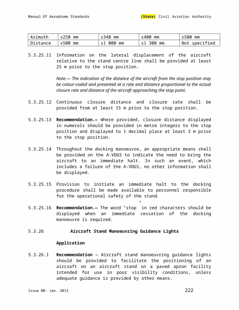
Manual Of Aerodrome Standards (State) Civil Aviation Authority
duties, and receive recurrent instruction at least every 24 consecutive calendar months.
(b) Must be able to explain purpose of and safely perform periodic inspections and checks needed to keep equipment operational and functioning safely.
(c) Must understand and be able to explain what should be done when a required component of fuel farm, mobile fueler, pit or cabinet is inoperable.
(d) Must understand the basic fire triangle and be able to identify the more common ignition sources found on airports.
(e) Must understand and be able to explain what should be done if fuel leak or spill occurs.
(f) Must understand and be able to generally explain static-generation/retention misting of fuels and the dangers associated with filtering and pumping fuels to and from storage tanks, mobile fuelers and aircraft.
(g) Must understand and be able to explain the hazards of atmospheric electrical phenomena, including lightning and static charging of aircraft in flight.
(h) Must understand and be able to explain main features of proper firefighting technique using, and demonstrating use of, the fire extinguishers normally at fuel farms and on fuelers, pit and cabinets.
(i) Must understand and be able to explain defueling procedures and precautions.
(j) Must maintain records of individual training and recurrent training.
9.13.3.2 Training for Line Personnel
Line personnel:
(a) For all aviation fueling agents, must be required to show that all employees who fuel aircraft, accept fuel shipments or otherwise handle fuel has received at least on-the job training and recurrent instruction every 24 consecutive calendar months in fire safety from the supervisor that has completed an aviation fuel training course that has been approved by the Authority.
(b) Must be able to understand purpose of and safely perform periodic inspections and checks needed to keep equipment operational and functioning safely.
Issue 00: Jan. 2013 222

Manual Of Aerodrome Standards (State) Civil Aviation Authority
(c) Must understand what should be done when required component of fuel farm, mobile fueler, pit or cabinet is inoperable.
(d) Must understand the basic fire triangle and be able to identify the more common ignition sources found on aerodromes.
(e) Must understand what should be done if fuel leak or spill occurs.
(f) Must understand static-generation and retention misting of fuels and the dangers associated with filtering and pumping fuels to and from storage tanks, mobile fuelers and aircraft.
(g) Must understand the hazards of atmospheric electrical phenomena, including lightning and static charging of aircraft in flight
(h) Must understand the main features of proper fire-fighting technique using, and demonstrating use of, the fire extinguishers normally at fuel farms and on fuelers, pit or cabinets.
(i) Must understand the dangers of defueling.
9.13.3.3 Clothing and Footwear
Fueling personnel must be appropriately clothed. Garments will be other than silk, polyesters, nylon with wool or other static generating fabrics; shoes containing no taps, hobnails or other material which could generate sparks on pavement.
9.13.3.4 Other
Fueling personnel must not carry on their persons at any time in, on or within 30.48m of any tank, dock, storage area, fueler or aircraft any igniting device, including safety matches, strike-anywhere matches, cigarette lighter or other items which could become ignition sources if operated, bumped, hit or dropped.
9.13.3.5 Supervision
Fueling personnel must be adequately supervised and periodically checked to ensure training and knowledge levels are maintained, all equipment and required components are kept fully operational, required periodic checks and inspections are made when due, required records are kept and that proper quantity and grade, clean, dry, on specification fuel is routinely delivered to the proper aircraft.
9.13.3.6 Fuel Farm, Fueler and Pit Operations
Fueling Staff:
(a) Must ensure that only qualified personnel are allowed to operate fuel farm or equipment or to fuel aircraft.
Issue 00: Jan. 2013 223

Manual Of Aerodrome Standards (State) Civil Aviation Authority
(b) Must ensure fueling is performed outside only, never in a building.
(c) Must ensure fuelers are never parked closer than 3.048m from each other, 15.24m from any building or aircraft not being fueled or defueled and during loading and fueling operations, 30.48m from smokers or other visible sources of ignition.
(d) Must ensure that before all unloading, loading, fueling and defueling operations are begun, all motors, engines, radios and other electrical and mechanical equipment, except only auxiliary power units not needed for that specific operation, are turned off and kept off.
(e) Must ensure that before opening any aircraft or fueler tank or commencing fueling operations and at all times during fuel transfer at least a bonding wire is connected between fueler being loaded and the loading dock ground or between the fueler, pit, cabinet and the aircraft being fueled.
(f) Must before commencing loading of any fueler or fueling any aircraft, ensure that all fuel farm, fueler, pit and cabinet equipment to be used is in good operating condition; that the tank and filter or filter/separator involved have been sumped in the previous 24 hours and that the fuel about to be loaded or pumped into the airplane is free of contaminants and of proper color, smell, feel and type and is clear and bright.
(g) Must ensure that mobile fueler loading and aircraft fueling is conducted only when the deadman control is operable and used to control fuel flow.
(h) Must ensure that fuel farm and all equipment are kept neat and free of trash or debris that could cause or contribute to fuel contamination or fire.
(i) Must ensure that all fire extinguishers area checked for charge and condition at least semi-annually.
(j) Must ensure that fuel service operations will be suspended when there are lightning discharges in the immediate vicinity of the aerodrome.
9.13.4 Fueler Records
9.13.4.1 Fueler Staff and Supervisors
Fueler staff and supervisors must develop and maintain for at least 12 months records adequate to at least show:
(a) Checks and any subsequent corrective action taken made on equipment required by these standards.
Issue 00: Jan. 2013 224

Manual Of Aerodrome Standards (State) Civil Aviation Authority
(b) Training given and qualifications on achievements of all fueling staff on the aerodrome.
9.13.4.2 Inspections
These records must be made available for inspection by the Fue l l ing agentupon request.
9.13.4.3 Proof of Training
Each aerodrome aviation fueling agent must be required to provide written proof to the aerodrome operator once a year that:
(a) At least one supervisor has completed an aviation fuel training course in fire safety that has been acceptable by the Authority.
(b) All other employees who fuel aircraft, accept fuel shipments or otherwise handle fuel have received at least on-the-job training in fire safety.
9.13.5 Inspection Schedule
Authority aircraft rescue and firefighting personnel will inspect each airport tenant fueling agent's fuel storage areas, mobile fuelers and fuel cabinets for compliance to the above fire safety fuel standards. Quarterly safety inspections must be conducted.
9.13.6 Inspection Forms
Attached forms are the safety survey forms that must be used for the quarterly and follow-up inspections. The completed survey records must be maintained in the office of the Director of Aerodrome and Airspace Standards for at least 12 months.
9.13.7 Corrective Action
Upon completion of any safety inspection, the inspector and the airport tenant fueling agent supervisor will discuss and sign the safety survey form. The airport tenant fueling agent will be required to take immediate corrective action whenever notified of noncompliance with these standards. A follow up inspection will be scheduled to confirm compliance. If the corrective action is not accomplished within a reasonable period of time, the fuelling agent must notify the Authorit
9.14 Runway Incursion Prevention
Issue 00: Jan. 2013 225
Manual Of Aerodrome Standards (State) Civil Aviation Authority
9.14.1 The aerodrome operator shall establish and implement runway safety programmes designed to remove hazards and minimize residual risk of runway incursions, to reduce active failures and severity of their consequences.
9.14.2 The aerodrome operator’s runway safety programme shall begin with the establishment of a runway safety team. The runway safety team shall comprise relevant specialist, persons or organisations whose functions or activities have a bearing with operational activities at the aerodrome.
9.14.3 The runway incursion prevention programme shall seek to identify hazards associated with runway incursion by paying attention to the following, among other local factors:
(a) aerodrome visual aids i.e aeronautical ground lighting, markings and signs;
(b) complexity of the aerodrome layout;
(c) volume of traffic ;
(d) capacity-enhancing procedures;
(e) movement of vehicles;
(f) Aerodrome works
(g) ATC and Pilot practices;
9.14.4 The runway incursion prevention programme shall employ the principles of safety management in minimising all the risk arising from identified
hazards of runway incursion.
Issue 00: Jan. 2013 226

Manual Of Aerodrome Standards (State) Civil Aviation Authority
CHAPTER 10. AERODROME MAINTENANCE
10.1 General
10.1.1 A maintenance programme, including preventive maintenance shall be established at an aerodrome to maintain facilities in a condition which does not impair the safety, regularity or efficiency of air navigation.
Note 1 — Preventive maintenance is programmed maintenance work done in order to prevent a failure or degradation of facilities.
Note 2 — “Facilities” are intended to include such items as pavements, visual aids, fencing, drainage systems and buildings.
10.1.2 Recommendation — The design and application of the maintenance programme should observe Human Factors principles.
Note — Guidance material on Human Factors principles can be found in the ICAO Human Factors Training Manual(Doc 9683).
10.2. Pavements
10.2.1 The surface of all movement areas including pavements (runways, taxiways, aprons) and adjacent areas shall be inspected and their conditions monitored regularly as part of an aerodrome preventive and corrective maintenance programme with the objective of avoiding and eliminating any loose objects/debris that might cause damage to aircraft or impair the operation of aircraft systems.
Note1 — See 2.9.3 for inspection of movement areas.
Note 2.— Guidance on carrying out daily inspections of the movement area is given in the Airport Services Manual (Doc 9137), Part 8, the Manual of Surface Movement Guidance and Control Systems (SMGCS) (Doc 9476) and the Advanced Surface Movement Guidance and Control Systems (A-SMGCS) Manual (Doc 9830).
Note 3.— Additional guidance on sweeping/cleaning of surfaces is contained in the Airport Services Manual (Doc 9137), Part 9.
Note 4.— Guidance on precautions to be taken in regard to the surface of shoulders is given in Attachment A, Section 8, and the Aerodrome Design Manual (Doc 9157), Part 2.
10.2.2 The surface of a runway shall be maintained in a condition such as to preclude formation of harmful irregularities.
Issue 00: Jan. 2013 227

Manual Of Aerodrome Standards (State) Civil Aviation Authority
Note —See Attachment A, Section 5 of this Part
10.2.3 Measurements of the friction characteristics of a runway surface shall be made periodically with a continuous friction measuring device using self-wetting features.
Note 1— Guidance on evaluating the friction characteristics of a runway is provided in Attachment A, Section 7 of this Part. Additional guidance is included in the Advisory Circular –(AC Number) and ICAO Airport Services Manual(Doc 9137), Part 2.
10.2.4 Corrective maintenance action shall be taken when the friction characteristics for either the entire runway or a portion thereof are below a minimum friction
level specified in Table 10-1
Note — A portion of the runway in the order of 100m long may be considered significant for maintenance or reporting action
10.2.5 Recommendation— Corrective maintenance action should be considered when the friction characteristic for either the entire runway or a portion thereof are below a maintenance level specified in Table 10-1
Table 10-1 – Design objective, maintenance planning level and minimum friction levels of runways in use
TestEquipment
Test tire Testspeed(km/h)
Testwaterdepth(mm)
Designobjectivefor newsurface
Maintenanceplanninglevel
MinimumfrictionlevelType Pressure
(kPa)(1) (2) (3) (4) (5) (6) (7)Mu-meterTrailer
A
A
70
70
65
95
1.0
1.0
0.72
0.66
0.52
0.38
0.42
0.26
SkiddometerTrailer
B
B
210
210
65
95
1.0
1.0
0.82
0.74
0.60
0.47
0.50
0.34
SurfaceFrictionTesterVehicle
B
B
210
210
65
95
1.0
1.0
0.82
0.74
0.60
0.47
0.50
0.34
RunwayFrictionTesterVehicle
B
B
210
210
65
95
1.0
1.0
0.82
0.74
0.60
0.54
0.50
0.41
TATRAFrictionTesterVehicle
B
B
210
210
65
95
1.0
1.0
0.76
0.67
0.57
0.52
0.48
0.42
Issue 00: Jan. 2013 228

Manual Of Aerodrome Standards (State) Civil Aviation Authority
GRIPTESTERTrailer
C
C
140
140
65
95
1.0
1.0
0.74
0.64
0.53
0.36
0.43
0.24
10.2.6 Recommendation — When there is reason to believe that the drainage characteristics of a runway, or portions thereof, are poor due to slopes or depressions, then the runway friction characteristics should be assessed under natural or simulated conditions that are representative of local rain and corrective maintenance action should be taken as necessary.
10.2.7 When a taxiway is used by turbine-engined aeroplanes, the surface of the taxiway shoulders shall be maintained so as to be free of any loose stones or other objects that could be ingested by the aeroplane engines.
Note — Guidance on this subject is given in the ICAO Aerodrome Design Manual(Doc 9157), Part 2.
10.2.8 The surface of a paved runway shall be maintained in a condition so as to provide good friction characteristics and low rolling resistance. Standing water, mud, dust, sand, oil, rubber deposits and other contaminants shall be removed as rapidly and completely as possible to minimize accumulation.
Note— Not applicable
10.2.9 Not applicable.
10.2.10 Not applicable.
10.2.11 Not applicable.
10.2.12 Not applicable
10.2.13 Chemicals which may have harmful effects on aircraft or pavements or chemicals which may have toxic effects on the aerodrome environment, shall not be used.
10.3. Runway Pavement Overlays
Note — The following specifications are intended for runway pavement overlay projects when the runway is to be returned to an operational status before overlay of the entire runway is complete thus normally necessitating a temporary ramp between the new and old runway surfaces. Guidance on overlaying
Issue 00: Jan. 2013 229

Manual Of Aerodrome Standards (State) Civil Aviation Authority
pavements and assessing their operational status is given in the ICAO Aerodrome Design Manual(Doc 9157), Part 3.
10.3.1 The longitudinal slope of the temporary ramp, measured with reference to the existing runway surface or previous overlay course, shall be:
(a) 0.5 to 1.0 per cent for overlays up to and including 5 cm in thickness; and
(b) not more than 0.5 per cent for overlays more than 5 cm in thickness.
10.3.2 Recommendation — Overlaying should proceed from one end of the runway toward the other end so that based on runway utilization most aircraft
operations will experience a down ramp.
10.3.3 Recommendation — The entire width of the runway should be overlaid during .each work session.
10.3.4 Before a runway being overlaid is returned to a temporary operational status, a runway centre line marking conforming to the specifications in Section 5.2.3 of this Manual shall be provided. Additionally, the location of any temporary threshold shall be identified by a 3.6 m wide transverse stripe.
10.4.0 Visual Aids
Note — These specifications are intended to define the maintenance performance level objectives. They are not intended to define whether the lighting system is operationally out of service.
10.4.1 A light shall be deemed to be unserviceable when the main beam average intensity is less than 50 per cent of the value specified in the appropriate figure in ICAO Annex 14, Appendix 2. For light units where the designed main beam average intensity is above the value shown in ICAO Annex 14, Appendix 2, the 50 per cent value shall be related to that design value.
10.4.2 A system of preventive maintenance of visual aids shall be employed to ensure lighting and marking system reliability.
Note — Guidance on preventive maintenance of visual aids is given in the ICAO Airport Services Manual(Doc 9137), Part 9.
10.4.3 Recommendation — The system of preventive maintenance employed for a precision approach runway category II or III should include at least the following checks:
(a) visual inspection and in-field measurement of the intensity, beam spread and orientation of lights included in the approach and runway lighting systems;
Issue 00: Jan. 2013 230

Manual Of Aerodrome Standards (State) Civil Aviation Authority
(b) control and measurement of the electrical characteristics of each circuitry included in the approach and runway lighting systems; and
(c) control of the correct functioning of light intensity settings used by air traffic control.
10.4.4 Recommendation — In-field measurement of intensity, beam spread and orientation of lights included in approach and runway lighting systems for a precision approach runway category II or III should be undertaken by measuring all lights, as far as practicable, to ensure conformance with the applicable specification of ICAO Annex 14, Appendix 2.
10.4.5 Recommendation — Measurement of intensity, beam spread and orientation of lights included in approach and runway lighting systems for a precision approach runway category II or III should be undertaken using a mobile measuring unit of sufficient accuracy to analyze the characteristics of the individual lights.
10.4.6 Recommendation — The frequency of measurement of lights for a precision approach runway category II or III should be based on traffic density, the local pollution level, the reliability of the installed lighting equipment and the continuous assessment of the results of the in-field measurements but in any event should not be less than twice a year for in-pavement lights and not less than once a year for other lights.
10.4.7 The system of preventive maintenance employed for a precision approach runway category II or III shall have as its objective that, during any period of category II or III operations, all approach and runway lights are serviceable, and that in any event at least:
(a) 95 per cent of the lights are serviceable in each of the following particular significant elements:
(1) precision approach category II and III lighting system, the inner 450 m;
(2) runway centre line lights;
(3) runway threshold lights; and
(4) runway edge lights;
(b) 90 per cent of the lights are serviceable in the touchdown zone lights;
(c) 85 per cent of the lights are serviceable in the approach lighting system beyond 450 m; and
(d) 75 per cent of the lights are serviceable in the runway end lights.
In order to provide continuity of guidance, the allowable percentage of unserviceable lights shall not be permitted in such a way as to alter the basic
Issue 00: Jan. 2013 231

Manual Of Aerodrome Standards (State) Civil Aviation Authority
pattern of the lighting system. Additionally, an unserviceable light shall not be permitted adjacent to another unserviceable light, except in a barrette or a crossbar where two adjacent unserviceable lights may be permitted.
Note — With respect to barrettes, crossbars and runway edge lights, lights are considered to be adjacent if located consecutively and:
laterally: in the same barrette or crossbar; or
longitudinally: in the same row of edge lights or barrettes.
10.4.8 The system of preventive maintenance employed for a stop bar provided at a runway-holding position used in conjunction with a runway intended for operations in runway visual range conditions less than a value of 350 m shall have the following objectives:
(a) no more than two lights will remain unserviceable; and
(b) two adjacent lights will not remain unserviceable unless the light spacing is significantly less than that specified.
10.4.9 The system of preventive maintenance employed for a taxiway intended for use in runway visual range conditions less than a value of 350 m shall have as its objective that no two adjacent taxiway centre line lights be unserviceable.
10.4.10 The system of preventive maintenance employed for a precision approach runway category I shall have as its objective that, during any period of category I operations, all approach and runway lights are serviceable, and that in any event at least 85 per cent of the lights are serviceable in each of the following:
(a) precision approach category I lighting system;
(b) runway threshold lights;
(c) runway edge lights; and
(d) runway end lights.
In order to provide continuity of guidance an unserviceable light shall not be permitted adjacent to another unserviceable light unless the light spacing is significantly less than that specified.
Note — In barrettes and crossbars, guidance is not lost by having two adjacent unserviceable lights.
10.4.11 The system of preventive maintenance employed for a runway meant for take-off in runway visual range conditions less than a value of 550 m shall have as its objective that, during any period of operations, all runway lights are serviceable and that in any event:
Issue 00: Jan. 2013 232

Manual Of Aerodrome Standards (State) Civil Aviation Authority
(a) at least 95 per cent of the lights are serviceable in the runway centre line lights (where provided) and in the runway edge lights; and
(b) at least 75 per cent of the lights are serviceable in the runway end lights.
In order to provide continuity of guidance, an unserviceable light shall not be permitted adjacent to another unserviceable light.
10.4.12 The system of preventive maintenance employed for a runway meant for take-off in runway visual range conditions of a value of 550 m or greater shall have as its objective that, during any period of operations, all runway lights are serviceable and that, in any event, at least 85 per cent of the lights are serviceable in the runway edge lights and runway end lights. In order to provide continuity of guidance, an unserviceable light shall not be permitted adjacent to another unserviceable light.
10.4.13 During low visibility procedures the aerodrome operator shall restrict construction or maintenance activities in the proximity of aerodrome electrical systems.
Issue 00: Jan. 2013 233
Manual Of Aerodrome Standards (State) Civil Aviation Authority
PART IIAERODROME WORK SAFETY, SAFETY MANAGEMENT SYSTEM AND ACCIDENT/
INCIDENT REPORTING AND INVESTIGATION PROCEDURES
Issue 00: Jan. 2013 234

Manual Of Aerodrome Standards (State) Civil Aviation Authority
CHAPTER 1. AERODROME WORK SAFETY
1.1 Introduction
1.1.1 An aerodrome operator shall plan and implement works to be carried out at an aerodrome so as not to create any hazard to aircraft operations or confusion to pilots. The Aerodrome Manual submitted by an aerodrome operator shall include details of the procedures for planning and safe carrying out of such work activities at the aerodrome.
1.1.2 An aerodrome operator shall, in his Aerodrome Manual, address how aerodrome works are to be carried out so that:
(a) where the works are of a nature that they will disrupt operations, these works shall be carried out with proper planning in advance; and
(b) where the works are of a minor/maintenance nature, these works may be carried out as time-limited works where normal aircraft operations are not disrupted and the movement area can be restored to normal safety standards and any obstacle created by those works removed in not more than 10 minutes. Depending on the nature and extent of each activity, time-limited works may include minor maintenance of markings and lights, grass mowing, sweeping of aircraft pavements, surveys and inspections, etc.
1.1.3 At a controlled aerodrome, the air traffic control unit may, at the request of the aerodrome operator, vary the time limits in section II.1.1.2 (b) above for restoring normal safety standards or resuming aerodrome works. A variation under this paragraph is subject to such conditions as the air traffic control unit may impose.
1.2 Aerodrome Work Plans
1.2.1 Unless an aerodrome is closed during works in progress, or the work is of an emergency nature, an aerodrome operator shall not carry out aerodrome works, other than time-limited works, without proper planning in advance.
1.2.2 A plan shall be established, setting out the arrangements for carrying out those aerodrome works in coordination with all other operational, maintenance and development activities at the aerodrome.
1.2.3 When preparing a work plan, an aerodrome operator shall consult:
(a) commercial air transport operators using the aerodrome;
Issue 00: Jan. 2013 235

Manual Of Aerodrome Standards (State) Civil Aviation Authority
(b) the aerodrome’s air traffic control unit; and
(c) if the work plan may affect its operations, the Rescue and Fire Fighting Service unit at the aerodrome
so that the scope and impact of work is understood by related aerodrome users and service providers and to ensure the safety of aircraft operations at the aerodrome.
1.2.4 The aerodrome operator shall ensure that clear and ample prior notification is provided to the Aeronautical Information Services, the aerodrome air traffic control unit, aircraft operators and other users or service providers of the aerodrome. Such notification shall include timely and accurate promulgation of AIP Supplements or NOTAMs, with clear details of the extent and period of works.
1.2.5 An aerodrome operator shall submit, and thereafter provide an explanation of his work plan, and any alterations or updates thereof, to the XCAA before commencing the aerodrome works. The aerodrome operator can only be allowed to commence the aerodrome works if the work plan is acceptable to the Authority.
1.2.6 Aerodrome works, for which a work plan is required, shall be carried out in accordance with the arrangements set out in the work plan and any subsequent alterations or updates.
1.2.7 The work plan shall address details of any special requirement or restrictions arising during or on completion of the works.
1.2.8 The work plan shall outline details, if any, of special arrangements to be made during works if emergencies or adverse weather conditions occur.
1.2.9 A work plan may not be required if the aerodrome operator closes the aerodrome to aircraft operations while aerodrome works are being carried out. XCAA, commercial air transport operators and all organisations and persons likely to be affected by the closure shall be given reasonable notice of intention to close the aerodrome.
1.2.10 An aerodrome operator shall not close the aerodrome to aircraft operations due to aerodrome works unless an AIP Supplement or a NOTAM giving notice of the closure has been issued not less than 14 days before the closure takes place.
1.2.11 A work plan is not required for emergency aerodrome works carried out to repair damage to part of the manoeuvring area, or to remove an obstacle, or if the works do not require any restrictions to aircraft operations. Where practicable, a NOTAM giving the nature and time and date of the commencement of the urgent repair works should be issued, as early as possible, before the commencement of the works.
Issue 00: Jan. 2013 236

Manual Of Aerodrome Standards (State) Civil Aviation Authority
1.3 Management and Control of Aerodrome Works
1.3.1 An aerodrome operator shall ensure that aerodrome works are carried out in accordance with the requirements of this Manual.
1.3.2 An aerodrome operator shall appoint a person responsible for the safe and proper execution of each item of aerodrome works. This person shall be required to:
(a) ensure the safety of aircraft operations is not affected by theaerodrome work plan;
(b) ensure that, where applicable, the aerodrome works are notified by the issue of an AIP Supplement or a NOTAM and that the text of each AIP Supplement or NOTAM pertaining to such notification conveys the information on operational restrictions accurately and clearly to aerodrome users and service providers;
(c) supply the air traffic control unit with whatever information necessary to ensure the safety of aircraft operations;
(d) discuss with the work organisations involved, on a regular basis, any matters necessary to ensure the safety of aircraft operations;
(f) ensure that vehicles, plant and equipment carrying out aerodrome works are properly marked and lit or are properly supervised;
(g) ensure that all requirements under the work plan pertaining to vehicles, plant and equipment and materials are compiled with;
(h) ensure that access routes to work areas are in accordance with that designated in the work plan and are clearly identified and that access is restricted to these routes;
(i) ensure that excavation is carried out in accordance with the work plan and relevant requirements, and in particular, that sufficient precautions are taken so as to avoid damage or loss of calibration to any underground power or control cable, utilities or other services associated with a precision approach and landing system, any navigational aid or facility or equipment essential for the safety of aerodrome operations;
(j) report immediately to the aerodrome air traffic control unit and the aerodrome operator any incident, or damage to facilities, likely to affect air traffic control services or the safety of aircraft;
(k) provide adequate supervisory duty at the work areas while major works are in progress and the aerodrome is open to aircraft operations;
Issue 00: Jan. 2013 237

Manual Of Aerodrome Standards (State) Civil Aviation Authority
(l) ensure that the aerodrome air traffic control unit is kept informed of the radio call signs of vehicles used by the work organizations that are operating in the aircraft movement areas;
(m) remove vehicles, plant and personnel from the movement area immediately, where necessary, to ensure the safety of aircraft operations;
(n) ensure that the movement area is safe for normal aircraft operations following the removal of vehicles, plant and equipment and personnel from the work areas;
(o) in the case of time-limited works, ensure that the work areas are restored to normal safety standards not less than 5 minutes before the time scheduled for opening the work areas to aircraft operations; and
(p) ensure that floodlighting or any other lighting required for carrying out aerodrome works is shielded so as not to present a hazard to aircraft operations.
1.3.3 The person responsible for the aerodrome works shall be satisfied that the work plan is adequately prepared and that sufficient safety measures are put in place on the work site at all times during the execution of the aerodrome works when the aerodrome is open to aircraft operations.
1.3.4 An aerodrome operator shall take all reasonable measures to ensure that aerodrome works are well-organised and that all work personnel carries out aerodrome works in a manner that will ensure the safety of aircraft operations.
1.3.5 Persons, vehicles, plant and equipment required for carrying out aerodrome works must not be permitted to enter the movement area or remain on it except for the purpose of carrying out those works.
1.3.6 Procedures for entering the work areas shall be addressed in the work plan.
1.4 Markers, Markings and Lights
1.4.1 Aerodrome markers, markings, signs and lights required for, or affected by, aerodrome works shall be adjusted or installed in accordance with the
appropriate aerodrome standards.
1.4.2 Parts of the movement area that are unserviceable as a result of the aerodrome works being carried out shall be marked and lit in accordance with the appropriate aerodrome standards.
1.4.3 All obstacles created as a result of aerodrome works being carried out shall be marked and lit in accordance with the appropriate aerodrome standards.
1.4.4 Vehicles and plant used in carrying out aerodrome works shall be marked and lit, where necessary, in accordance with the appropriate aerodrome standards.
Issue 00: Jan. 2013 238

Manual Of Aerodrome Standards (State) Civil Aviation Authority
1.5 Communication Equipment
1.5.1 At a controlled aerodrome, a vehicle used by work parties carrying out aerodrome works on the movement area shall be equipped with a radio for two-way communications with the aerodrome air control tower unit.
1.5.2 For the purpose of communication with the air traffic control unit, each vehicle used for carrying out aerodrome works on the movement area should be given a call-sign.
1.5.3 Any vehicle or plant that is not:
(a) marked or lit in accordance with section 1.4 above; or
(b) if applicable, equipped with a two-way radio; may only be used in carrying out aerodrome works if it is:
1) used under the direct supervision of another vehicle that is equipped with a two-way radio set and which is responsible for escorting the vehicle or plant without radio when carrying out aerodrome works; or
2) used only within the limits of appropriately marked and lit work areas.
1.5.4 The drivers of vehicles equipped with a radio for two-way communications with the aerodrome air traffic control unit shall be properly trained and be responsible for checking that their radio sets are switched on and serviceable at all times when working on the movement area.
1.6 Works near Aircraft Movement Areas
1.6.1 The aerodrome operator shall refer to chapters 6 and 7 of this Manual and ICAO Airport Services Manual (Doc 9137) Part 6 – Control of Obstacles to determine the extent of work allowed near aircraft movement areas.
1.6.2 Works on or near aircraft movement areas or runway strips shall be carried out as quickly as practicable to minimise any potential risks arising out of changes associated with the works in progress.
1.6.3 Where works are to be undertaken in the vicinity of navigational or landing aids located within the runway strips, considerations shall be taken to ensure that neither the works nor vehicles or plant associated with the works may affect the performance of the aids.
1.7 Completion
Issue 00: Jan. 2013 239

Manual Of Aerodrome Standards (State) Civil Aviation Authority
1.7.1 On the completion of aerodrome works and restoration of normal safety standards to the movement area, the aerodrome operator shall cancel any AIP Supplement or NOTAM issued to advise of those works.
1.7.2 An aerodrome operator shall be required to inspect his aerodrome, as circumstances require, to ensure aviation safety during and immediately after any period of construction or repair of an aerodrome facility or equipment that is critical to the safety of aircraft operations, and at any other time when there are conditions at the aerodrome that could affect aviation safety.
1.8 Content of Work Safety Plan
A work safety plan shall contain at least the following information:
(a) Description of the construction project:
Provide a full description of the planned construction project.
(b) Stages/phases of the construction & schedules:
List the different stages of the construction activities with anticipated start and finish dates.
(c) Types & frequency of air traffic:
List the types of aircraft and number of daily movements anticipated during the construction period.
(d) Disruptions to air traffic:
What will be the impact on and disruptions to the air traffic as listed above.
(e) Position and height of equipment (Relative to Runways & Taxiways):
Provide the location and maximum working height of the construction equipment or vehicles and where that equipment will be working in relationship to the taxiway or runway edges/ends. This information is required to assess the impact on Obstacle Limitation Surfaces.
(f) Work adjacent to Runway/Taxiway:
Temporary hazards on runway strips. Which zone will you be working in, which restriction and operational conditions will apply to your project?
(g) Markings, barriers and lighting provided:
Issue 00: Jan. 2013 240
Manual Of Aerodrome Standards (State) Civil Aviation Authority
Describe all markings, barriers and lighting to be used to indicate unserviceable areas of the aerodrome.
(h) Displaced and/or Relocated Thresholds:
If the project will require a displaced or relocated threshold, provide an explanation as to why this is required, what percentage slope the calculations are based on, how will the new threshold be marked and lighted, what buffer is being provided for jet or prop blast consideration?
(i) Declared distance during all phases:
Based on the above calculation what will be the revised declared distances?
(j) Access control, vehicle operations and Escorts:
How will vehicles and equipment access the construction site, will Airport Vehicle Operator Permit be issued, are radio licenses required, will vehicles be escorted, whom will be providing the escorts?
(k) Communications Plan (Prior to Construction & During Construction):
Every construction project requires a Communication Plan. The Plan will cover communication with the aerodrome clients/users, ATS and
NDCA during all phases of the project; #1: Planning Phase, #2: Pre-construction Phase #3: Construction Phase.
Airport Ops ↔ ATS;ATS ↔ Construction Site;Airport Ops ↔ Construction Site;Airport Ops ↔ Users (Stakeholders);Airport Ops ↔ NDCA.
(l) NOTAMs as per the NOTAM procedure manual:
Provide a draft of all anticipated NOTAMS. NOTAMs revising declared distances must be pre-approved by XCAA.
(m) Drawing or Blueprints:
Provide any drawings required to support your Plan of Construction Operation. It is the aerodrome operator’s responsibility to ensure the drawings and final product meet Aerodrome Certification requirements.
Issue 00: Jan. 2013 241

Manual Of Aerodrome Standards (State) Civil Aviation Authority
CHAPTER 2 – SAFETY MANAGEMENT
2.1 Introduction
2.1.1 The Authority shall establish a State safety programme in order to achieve an acceptable level of safety in civil aviation.
Note.— A framework for the implementation and maintenance of a State safety programme is contained in Attachment C, and guidance on a State safety programme is contained in the Safety Management Manual (SMM) (Doc 9859).
2.1.2 The acceptable level of safety to be achieved shall be established by the Authority.
Note.— Guidance on defining an acceptable level of safety is contained in the Safety Management Manual (SMM) (Doc 9859).
2.1.3 The Authority shall require, as part of their State safety programme, that a certified aerodrome implement a safety management system.
2.1.4 Intentionally left blank
2.2 Safety management system-Scope and applicability 2.2.1 An aerodrome operator shall have in place a safety management system,
acceptable to the requirement as a minimum:
(a) identifies safety hazards;
(b) ensures that remedial action necessary to maintain an acceptable level of safety is implemented;
(c) provides for continuous monitoring and regular assessment of the safety level achieved; and
(d) aims to make continuous improvement to the overall level of safety.
2.2.2 In order to be acceptable to the Authority, aerodrome operator’s SMS shall meet the requirements set forth in XCAR and this chapter
2.2.3 This Chapter addresses aviation safety related processes and activities rather than occupational safety, environmental protection, or customer service quality.
Issue 00: Jan. 2013 242

Manual Of Aerodrome Standards (State) Civil Aviation Authority
2.2.4 An aerodrome operator is responsible for the safety of services or products contracted to or purchased from other organisations.
2.2.5 This Manual establishes the minimum acceptable requirements. The aerodrome operator can establish more stringent requirements.
2.3 General
2.3.1 Aerodrome operator shall establish, maintain and adhere to a Safety Management System (SMS) that is appropriate to the size, nature and complexity of the operations authorised to be conducted under its aerodrome certificate and the safety hazards and risks related to the operations.
2.4 Safety Policy and Objectives
2.4.1 General Requirements
2.4.1.1 An aerodrome operator shall define the organisation’s safety policy.
2.4.1.2 The safety policy shall be signed by the accountable executive of the organisation.
2.4.1.3 The safety policy shall be in accordance with all applicable legal requirements and international standards, best industry practices and shall reflect organisational commitments regarding safety.
2.4.1.4 The safety policy shall be communicated, with visible endorsement, throughout the organisation.
2.4.1.5 The safety policy shall include a clear statement about the provision of the necessary human and financial resources for its implementation.
2.4.1.6 The safety policy shall, inter alia, include the following objectives:
(a) commitment to implement an SMS;
(b) commitment to continual improvement in the level of safety;
© commitment to the management of safety risks;
(d) commitment to encourage employees to report safety issues;
(e) establishment of clear standards for acceptable behaviour; and
(f) Identification of responsibilities of management and employees with respect to safety performance.
Issue 00: Jan. 2013 243

Manual Of Aerodrome Standards (State) Civil Aviation Authority
2.4.1.7 The safety policy shall be reviewed periodically to ensure it remains relevant and appropriate to the organisation.
2.4.1.8 Aerodrome operator shall establish safety objectives for the SMS.
2.4.1.9 The safety objectives should be linked to the safety performance indicators, safety performance targets and safety requirements of the aerodrome operator SMS.
2.5 Organisational structure and responsibilities
2.5.1 An aerodrome operator shall identify an Accountable Executive to be responsible and accountable on behalf of the aerodrome operator for meeting the requirements of this Manual, and shall notify the Authority of the name of the person.
2.5.2 The Accountable Executive shall be a single, identifiable person who, irrespective of other functions, shall have the ultimate responsibility for the implementation and maintenance of the SMS.
2.5.3 The Accountable Executive shall have:
(a) full control of the human resources required for the operations authorised to be conducted under the aerodrome certificate;
(b) full control of the financial resources required for the operations authorised to be conducted under the aerodrome certificate;
© final authority over operations authorised to be conducted under the aerodrome certificate;
(d) direct responsibility for the conduct of the organisation‘s affairs; and
(e) Final responsibility for all safety issues.
2.5.4 An aerodrome operator shall establish the safety structure necessary for the implementation and maintenance of the aerodrome SMS.
2.5.5 An aerodrome operator shall identify the safety responsibilities of all members of senior management, irrespective of other responsibilities
2.5.6 Safety-related positions, responsibilities and authorities shall be defined, documented and communicated throughout the organisation.
2.5.7 An aerodrome operator shall identify a Safety Manager to be the member of management who shall be the responsible individual and focal point for the development and maintenance of an effective SMS.
2.5.8 The Safety Manager shall:
Issue 00: Jan. 2013 244

Manual Of Aerodrome Standards (State) Civil Aviation Authority
(a) Ensure that processes needed for the SMS are established, implemented and maintained;
(b) Report to the Accountable Executive on the performance of the SMS and on any need for improvement; and
(c) Ensure safety promotion throughout the organisation.
2.6 SMS implementation plan
2.6.1 An aerodrome operator shall develop and maintain an SMS implementation plan.
2.6.2 The SMS implementation plan shall be the definition of the approach the organisation will adopt for managing safety in a manner that will meet
the organisation’s safety needs.
2.6.3 The SMS implementation plan shall include the following:
(a) safety policy and objectives;(b) safety planning,(c) system description; (d) gap analysis;(e) SMS components;(f) safety roles and responsibilities; (g) safety reporting policy;(h) means of employee involvement; (i) safety training;(j) safety communication;(k) safety performance measurement; and(l) management review of safety performance.
2.6.4 The SMS implementation plan shall be endorsed by Accountable Executive of the organisation.
2.6.5 An aerodrome operator shall, as part of the development of the SMS implementation plan, complete a system description.
2.6.6 The system description shall include the following:
(a) the system interactions with other systems in the air transportation system;
(b) the system functions; (c) required human performance considerations of the system operation;
(d) hardware components of the system;(e) software components of the system;(f) related procedures that define guidance for the operation and use of the
system; (g) operational environment; and
Issue 00: Jan. 2013 245
Manual Of Aerodrome Standards (State) Civil Aviation Authority
(h) contracted and purchased products and services.
2.6.7 An aerodrome operator shall, as part of the development of the SMS implementation plan, complete a gap analysis, in order to:
(a) identify the safety arrangements and structures that may be existing throughout an organisation; and
(b) determine additional safety arrangements required to implement and maintain the organisation’s SMS.
2.6.8 The SMS implementation plan shall explicitly address the coordination between the SMS of the aerodrome operator and the SMS of other organisations the aerodrome operator must interface with during the provision of services.
2.7 Coordination of emergency response planning
2.7.1 An aerodrome operator shall develop and maintain or coordinate, as appropriate, an emergency response/contingency plan that shall ensure:
(a) orderly and efficient transition from normal to emergency operations; (b) designation of emergency authority;(c) assignment of emergency responsibilities;(d) coordination of efforts to cope with the emergency; and(e) safe continuation of operations, or return to normal operations as soon as
possible.
2.8 Documentation
2.8.1 An aerodrome operator shall develop and maintain SMS documentation, in paper or electronic form, to describe the following:
(a) safety policy;(b) safety objectives;(c) SMS requirements, procedures and processes;(d) responsibilities and authorities for procedures and processes; and(e) SMS outputs.
2.8.2 An aerodrome operator shall, as part of the SMS documentation, develop and maintain a Safety Management S y s t e m M a n u a l ( SMSM), t o c o m m u n i c a t e the o r g a n i s a t i o n ’ s approach to safety throughout the organisation.
2.8.3 The SMSM shall document all aspects of the SMS, and its contents shall include the following:
(a) scope of the safety management system; (b) safety policy and objectives;(c) safety accountabilities;
Issue 00: Jan. 2013 246

Manual Of Aerodrome Standards (State) Civil Aviation Authority
(d) key safety personnel;(e) documentation control procedures;(f) hazard identification and risk management schemes; (g) safety performance monitoring;(h) emergency response/contingency planning; (i) management of change; and(j) safety promotion.
2.9 Safety risk management
2.9.1 General
2.9.1.1 An aerodrome operator shall develop and maintain safety data collection and processing systems (SDCPS) that provide for the identification of hazards and the analysis, assessment and mitigation of safety risks.
2.9.1.2 An aerodrome operator’s SDCPS shall include reactive, proactive and predictive methods of safety data collection.
2.9.2 Hazard identification
2.9.2.1 An aerodrome operator shall develop and maintain formal means for effectively collecting, recording, acting on and generating feedback about hazards in operations, which combine reactive, proactive and predictive methods of safety data collection.
2.9.2.2 The hazard identification process shall include the following steps:
(a) reporting of hazards, events or safety concerns; (b) collection and storing the safety data;(c) analysis of the safety data; and(d) distribution of the safety information distilled from the safety data.
2.9.3 Risk management
2.9.3.1 An aerodrome operator shall develop and maintain a formal risk management process that ensures the analysis, assessment and mitigation of risks of consequences of hazards to an acceptable level.
2.9.3.2 The risks of the consequences of each hazard identified through the hazard identification processes described in 2.9.2.2 of this Manual shall be analyzed in terms of probability and severity of occurrence, and assessed for their tolerability.
2.9.3.3 The organisation shall define the levels of management with authority to make safety risk tolerability decisions.
Issue 00: Jan. 2013 247

Manual Of Aerodrome Standards (State) Civil Aviation Authority
2.9.3.4 The organisation shall define safety controls for each risk assessed as tolerable.
2.9.4 Internal safety investigations
2.9.4.1 An aerodrome operator shall as part of the SMS, develop and maintain formal processs for the internal investigation of occurrences that are not required to be investigated by or reported to the Authority.
2.10 Safety assurance
2.10.1 General
2.10.1.1 An aerodrome operator shall develop and maintain safety assurance processes to ensure that the safety risks controls developed as a consequence of the hazard identification and risk management activities under section 6 achieve their intended objectives.
2.10.1.2 Safety assurance processes shall apply to an SMS whether the activities and/or operations are accomplished internally or outsourced.
2.10.2 Safety performance monitoring and measurement
2.10.2.1 An aerodrome operator shall, as part of the SMS safety assurance activities, develop and maintain the necessary means to verify safety performance of the organisation in comparison with the approved safety policies and objectives, and to validate the effectiveness of implemented safety risk controls.
2.10.2.2 Safety performance monitoring and measurement means shall include the following:
(a) safety reporting;(b) safety audits; (c) safety surveys; (d) safety reviews; and(e) safety studies;
2.10.2.3 The safety reporting procedure shall set out the conditions to ensure effective safety reporting, including the condi t ions under which immunity from d i sc ip l i na ry action shall apply.
2.10.3 Management of change
2.10.3.1 An aerodrome operator shall, as part of the SMS safety assurance activities, develop and maintain a formal process for the management of change.
2.10.3.2 The formal process for the management of change shall:
Issue 00: Jan. 2013 248
Manual Of Aerodrome Standards (State) Civil Aviation Authority
(a) identify changes within the organisation which may affect established processes and services;
(b) describe the arrangements to ensure safety performance before implementing changes; and
(c) eliminate or modify safety risk controls that are no longer needed due to changes in the operational environment.
2.10.4 Continuous improvement of the safety system
2.10.4.1 An aerodrome operator shall, as part of the SMS safety assurance activities, develop and maintain formal processes to identify the causes of under-performance of the SMS, determine the implications in its operation, and to rectify situations involving below standard performance in order to ensure the continual improvement of the SMS.
2.10.4.2 Continuous improvement of the aerodrome operator SMS shall include:
(a) proactive and reactive evaluations of facilities, equipment, documentation and procedures, to verify the effectiveness of strategies for control of safety risks; and
(b) proactive evaluation of the individuals’ performance, to verify the fulfilment of safety responsibilities.
2.11 Safety promotion
2.11.1 General
2.11.1.1 An aerodrome operator shall develop and maintain formal safety training and safety communication activities to create an environment where the safety objectives of the organisation can be achieved.
2.11.2 Safety training
2.11.2.1 An aerodrome operator shall, as part of its safety promotion activities, develop and maintain a safety training programme that ensures that personnel are trained and competent to perform the SMS duties.
2.11.2.2 The scope of the safety training shall be appropriate to the individual’s involvement in the SMS.
2.11.2.3 The accountable executive shall receive safety awareness training regarding:
(a) safety policy and objectives;(b) SMS roles and responsibilities; and(c) safety assurance.
Issue 00: Jan. 2013 249

Manual Of Aerodrome Standards (State) Civil Aviation Authority
2.11.3 Safety communication
2.11.3.1 An aerodrome operator shall, as part of its safety promotion activities, develop and maintain formal means for safety communication, to:
(a) ensure that all staff is fully aware of the SMS; (b) convey safety critical information;(c) explain why particular safety actions are taken;(d) explain why safety procedures are introduced or changed; and(e) convey generic safety information.
2.11.3.2 Formal means of safety communication shall include:
(a) safety policies and procedures;(b) newsletters; and(c) bulletins.
2.12 Quality policy
2.12.1 An aerodrome operator shall ensure that the organisation quality policy is consistent with, and supports the fulfilment of the activities of the SMS.
2.13 Implementation of the SMS
2.13.1 This document proposes, but does not mandate, a phased implementation of an aerodrome operator SMS, which encompasses four phases.
2.13.2 Phase 1
2.13.2.1 Phase 1 should provide a blueprint on how the SMS requirements will be met and integrated to the organisation’s work activities, and an accountability framework for the implementation of the SMS:
2.13.2.2 Identify the accountable executive and the safety accountabilities of managers;
2.13.2.3 Identify the person (or planning group) within the organisation responsible for implementing the SMS;
2.13.2.4 Describe the system of certified aerodrome;
2.13.2.5 Conduct a gap analysis of the organisation’s existing resources compared with the national and international requirements for establishing an SMS;
2.13.2.6 Develop an SMS implementation plan that explains how the organisation will implement the SMS on the basis of national requirements and international SARPs, the system description and the results of the gap analysis;
2.13.2.7 Develop documentation relevant to safety policy and objectives; and
Issue 00: Jan. 2013 250
Manual Of Aerodrome Standards (State) Civil Aviation Authority
2.13.2.8 Develop and establish means for safety communication.
2.13.3 Phase 2
2.13.3.1 Phase 2 should put into practice those elements of the SMS implementation plan that refer to the safety risk management reactive processes:
(a) hazard identification and risk management using reactive processes;
(b) training relevant to:
1) SMS implementation plan components; and
2) safety risk management (reactive processes).
(c) documentation relevant to:
1) SMS implementation plan components; and
2) safety risk management (reactive processes).
2.13.4 Phase 3
2.13.4.1 Phase 3 should put into practice those elements of the SMS implementation plan that refer to the safety risk management proactive and predictive processes:
(a) hazard identification and risk management using proactive and predictive processes
(b) training relevant to:
1) SMS implementation plan components; and
2) safety risk management (proactive and predictive processes).
(c) documentation relevant to:
1) SMS implementation plan components; and
2) safety risk management (proactive and predictive processes).
2.13.5 Phase 4
2.13.5.1 Phase 4 should put into practice operational safety assurance:
(a) development of acceptable level(s) of safety;
(b) development of safety indicators and targets;
(c) SMS continuous improvement;
Issue 00: Jan. 2013 251

Manual Of Aerodrome Standards (State) Civil Aviation Authority
(d) training relevant to operational safety assurance; and
(e) documentation relevant to operational safety assurance.
CHAPTER 3 AERODROME ACCIDENT/INCIDENT REPORTING AND INVESTIGATION PROCEDURES
3.1 Aerodrome Occurrence Reporting
3.1.1 This chapter prescribes the requirements for reporting the occurrence or detection of defects, failures or malfunctions at an aerodrome, its components or equipment, which could jeopardise the safe operation of the aerodrome or cause it to become a danger to persons or property. The objectives of the Aerodrome Occurrence Report are as follows:
(a) To ensure that knowledge of these occurrences is disseminated so that other persons and organizations may learn from them.
(b) To enable an assessment to be made by those concerned (whether internal or external to the aerodrome operator) of the safety implications of each occurrence, both in itself and in relation to previous similar occurrences, so that they may take or initiate any necessary action.
3.2 Reportable Occurrences and Reporting Procedures
3.2.1 An aerodrome operator shall notify the Authority of any accident, serious incident, fatal or serious injury occurring at his aerodrome – in accordance with aerodrome operator’s standard operating procedures or as soon as practicable – and provide a detailed occurrence report thereafter.
3.2.2 The definitions for accident, serious incident and fatal or serious injury are as follows:
(a) Accident – See definition under Part 1 of this Manual.
Issue 00: Jan. 2013 252
Manual Of Aerodrome Standards (State) Civil Aviation Authority
(b) Serious incident – See definition under Part 1 of this Manual.
Examples are:
1) A near collision requiring an avoidance manoeuvre to avoid a collision or an unsafe situation or where an avoidance action would have been appropriate.
2) A controlled flight into terrain only marginally avoided.
3) An aborted take-off on a closed or engaged runway.
4) A take-off from a closed or engaged runway with marginal separation from an obstacle.
5) A landing or attempted landing on a closed or engaged runway
6) A take-off or landing incident such as undershooting, overrunning or running off the side of runways.
7) A major failure of any navigation aid when a runway is in use.
(c) Serious injury – See definition under section 1.2 of Part I.
3.2.3 The owner or operator of an aerodrome in (State) shall also notify the organization responsible for Accident Investigation where the accident or serious incident occurs on or adjacent to his aerodrome.
3.2.4 Information to be provided in the reporting and notification of an accident, serious incident or serious injury shall at least include, as far as possible, the following:
(a) the date and local time of occurrence;
(b) the exact location of the occurrence with reference to some easily defined geographical point ;
(c) detailed particulars of the parties involved, including the owner, operator, manufacturer, nationality, registration marks, serial numbers, assigned identities of aircraft and equipment;
(d) a detailed description of the sequence of events leading up to the incident;
(e) the physical characteristics, environment or circumstances of the area in which the incident occurred and an indication of the access difficulties or special requirements to reach the site;
Issue 00: Jan. 2013 253
Manual Of Aerodrome Standards (State) Civil Aviation Authority
(f) the identification of the person sending the notice and where the incident occurred, the means by which the investigator-in-charge may be contacted;
(g) in the case of an aircraft accident, the number of crew members, passengers or other persons respectively killed or seriously injured as a result of the accident; and
(h) a description of the follow-up action being taken after the incident has occurred.
3.3 Aerodrome Occurrence Records
3.3.1 An aerodrome operator shall establish and maintain Aerodrome Occurrence Reports for any accident, serious incident, serious injury or any occurrence or event that has a bearing on the safety of aerodrome operations.
3.3.2 Aerodrome Occurrence Reports should be used by an aerodrome operator to monitor and improve the level of operational safety, including reviews of safety standards required.
3.3.3 The Authority may require the aerodrome operator to produce and provide information contained in the Aerodrome Occurrence Report relating to any safety occurrence or event.
3.4 Aerodrome Accident/Incident Investigations
3.4.1 In the event of an accident or serious incident, an aerodrome operator shall carry out its own investigations.
3.4.2 The investigations carried out by the aerodrome operator shall be in addition to that carried out by the organization responsible for accident investigation.
3.4.3 The investigator, or team of investigators, shall be technically competent and shall either possess or have access to the background information, so that the facts and events are interpreted accurately. The investigations shall be a search to understand how the mishap happened, why it occurred, including organisational contributing factors, and to recommend action to prevent a recurrence, and shall not be intended to apportion blame.
3.4.4 The lesson learnt derived from an aerodrome incident/accident investigation shall be disseminated to staff to provide feedback for safety improvement.
3.4.5 The Authority shall require the aerodrome operator to produce and provide information contained in the aerodrome accident/incident investigation report relating to any such event.
3.4.6 An aerodrome operator shall inspect his aerodrome, as circumstances require, to ensure safety as soon as practicable after any aircraft accident or incident.
Issue 00: Jan. 2013 254

Manual Of Aerodrome Standards (State) Civil Aviation Authority
PART IIISUPPLEMENTARY STANDARDS ON AERODROME EMERGENCY PLANNING,
RESCUE AND FIRE FIGHTING, WILDLIFE HAZARD PLANNING AND MANAGEMENT
Issue 00: Jan. 2013 255
Manual Of Aerodrome Standards (State) Civil Aviation Authority
CHAPTER 1. AERODROME EMERGENCY PLANNING
1.1 Content
1.1.1 In an emergency plan, the aerodrome operator shall, at a minimum:
(a) identify the potential emergencies, including:
(1) an aircraft accident or incident:
(i) within the aerodrome boundaries, and
(ii) within a critical rescue and fire-fighting access area that extends 1000 m beyond the ends of a runway and
150 m at 90° outwards from the centerline of the runway including any part of that area outside the
aerodrome boundaries.
(2) an aircraft emergency declared by either air traffic services or a pilot,
(3) a fuel spill that spreads at least 1.5 m in any direction or exceeds 12 mm in depth,
(4) a medical emergency,
(5) a fire in which aerodrome operations or passenger safety is threatened,
(6) an emergency that is related to a special aviation event and that might have an impact on aerodrome
operations,
(7) a natural disaster, and
(8) any other emergency that is a threat or is likely to be a threat to the safety of persons or to the operation of the
aerodrome;
(b) identify the organisations at the aerodrome and the community organisations that are capable of providing assistance during an emergency at an aerodrome or in its vicinity, provide the telephone numbers and other contact information for each organisation and describe the type of assistance each can provide;
Issue 00: Jan. 2013 256
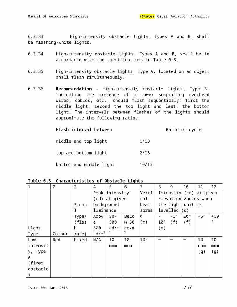
Manual Of Aerodrome Standards (State) Civil Aviation Authority
© identify the other resources available at the aerodrome and in the surrounding communities for use during emergency response or recovery operations and provide their telephone numbers and other contact information;
(d) describe for emergency situations, the lines of authority and the relationships between the organisations identified in the emergency plan and describe how actions will be coordinated among all and within each of the organisations;
(e) identify for emergency situations, the supervisors and describe the responsibilities of each;
(f) specify the positions occupied by the aerodrome personnel who will respond to an emergency and describe the specific emergency response duties of each;
(g) identify the on-scene commander and describe the commander's emergency response duties;
(h) provide Authorization for a person to act as an on-scene commander or a supervisor if they are not aerodrome personnel;
(i) set out the criteria to be used for positioning the on-scene commander within visual range of an emergency scene;
(j) set out the measures to be taken to make the on-scene commander easily identifiable at all times by all persons responding to an emergency;
(k) if initial on-scene control has been assumed by a person from a responding organizations, describe the procedure for transferring control to the on-scene commander;
(l) describe any training and qualifications required for the on- scene commander and the aerodrome personnel identified in the emergency plan;
(m) describe the method for recording any training provided to the on-scene commander and aerodrome personnel;
(n) describe the communication procedures and specify the radio frequencies to be used to link the operator of the aerodrome
with:
(1) the on-scene commander, and
Issue 00: Jan. 2013 257

Manual Of Aerodrome Standards (State) Civil Aviation Authority
(2) the providers of ground traffic control services (if applicable) and air traffic control services or any other flight information unit at the aerodrome;
(o) describe the communication procedures allowing the on-scene commander to communicate with the organisations identified in the emergency plan;
(p) identify the alerting procedures that:
(1) activate the emergency plan,
(2) establish the necessary level of response,
(3) allow immediate communication with the organisations identified in the emergency plan in accordance with the required level of response,
(4) if applicable, confirm the dispatch of each responding organisation;
(5) establish the use of standard terminology in communications, and
(6) establish the use of the appropriate radio frequencies as set out in the emergency plan;
(q) specify:
(1) the aerodrome communication equipment testing procedures,
(2) a schedule for the testing, and
(3) the method of keeping records of the tests;
(r) specify the location of the emergency coordination centre used to provide support to the on-scene commander;
(r) describe the measures for dealing with adverse climatic conditions and darkness for each potential emergency set out
in paragraph (a)(1);
(t) describe the procedures to assist persons who have been evacuated if their safety is threatened or airside operations are affected;
(u) describe the procedures respecting the review and confirmation of the following to permit the return of the aerodrome to operational
status after an emergency situation:
Issue 00: Jan. 2013 258
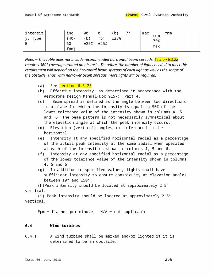
Manual Of Aerodrome Standards (State) Civil Aviation Authority
(1) emergency status reports,
(2) coordination with appropriate judicial authorities and the investigator designated by the accident investigation
entity regarding the accident site conditions,
(2) disabled aircraft removal,
(3) airside inspection results,
(4) accident or incident site conditions, and
(6) air traffic services and NOTAM coordination;
(v) describe the procedures for controlling vehicular flow during an emergency to ensure the safety of vehicles, aircraft and
persons;
(w) specify the procedures for issuing a NOTAM in the event of an emergency affecting the critical category for fire fighting
required, or changes or restrictions in facilities or services at the aerodrome during and after an emergency;
(x) describe the procedures for preserving evidences as it relates to :
(1) aircraft or aircraft part removal, and
(2) the site of the accident or incident;
(y) describe the procedures to be followed, after any exercise or the activation of the plan for an emergency that requires a full emergency standby, in the following cases:
(1) a post-emergency debriefing session with all participating organisations,
(2) the recording of the minutes of the debriefing session,
(3) an evaluation of the effectiveness of the emergency plan to identify deficiencies,
(4) changes, if any, to be made in the emergency plan, and
(5) partial testing subsequent to the modification of an emergency plan;
(z) describe:
Issue 00: Jan. 2013 259

Manual Of Aerodrome Standards (State) Civil Aviation Authority
(1) the process for an annual review and update of the emergency plan, and
(2) the administrative procedure for the distribution of copies of an updated version of the emergency plan to the aerodrome
personel who require them and to the community organisations identified in the plan; and
(3) the procedures to assist in locating an aircraft when the aerodrome receives notification that an
Emergency Locator Transmitter(ELT) or any advanced system of tracking aircraft in an emergency has been activated.
1.1.2 The aerodrome operator shall include a copy of the following documents in the emergency plan:
(a) the signed agreements, if any, between the aerodrome operator and the community organisations that provide emergency response
services to the aerodrome; and
(b) an aerodrome grid map.
1.2 On-Scene Commander
1.2.1 The on-scene commander shall be at the emergency site and shall not have other duties during an emergency, unless the life of a person is in
danger nearby and the on-scene commander is alone and has the ability to assist the person.
1.2.2 The aerodrome operator shall establish procedures that make the on- scene commander easily identifiable by all persons responding to an
emergency.
1.3 Aircraft Crash Charts and Aerodrome Grid Maps
1.3.1 For aircraft operating in a passenger or cargo configuration, the aerodrome operator shall make available to the emergency
coordination centre aircraft crash charts specific to the aircraft used by the air operators that use the aerodrome, and shall provide copies of the charts to the organisations responsible for fire-fighting services that are identified in the emergency plan; and the on-scene commander.
Issue 00: Jan. 2013 260

Manual Of Aerodrome Standards (State) Civil Aviation Authority
1.3.2 In the case of aircraft that have or may have a seating configuration of not more than nine passenger seats, the aerodrome operator may use,
instead of the aircraft crash charts referred to in section 1.3.1, other documents containing equivalent information.
1.3.3 The aerodrome operator shall develop and review and update annually, if necessary, an aerodrome grid map that includes a
minimum of:
(a) an area covering at least one kilometer around each runway;
(b) the aerodrome access roads and gates; and
(c) the location of meeting points to which persons and vehicles that are responding to an emergency situation proceed in order to
receive instructions.
1.3.4 The aerodrome operator shall provide copies of the aerodrome grid map to the aerodrome personnel and organisations identified in the
aerodrome emergency plan.
1.4 Personnel and Training
1.4.1 The aerodrome operator shall assign specific emergency response duties, other than those of an on-scene commander or a supervisor, only to
those aerodrome personnel who are identified in the emergency plan and who:
(a) are knowledgeable of their duties as described in the plan; and
(b) have the skills to carry out their duties.
1.4.2 The aerodrome operator shall assign to act as an on-scene commander or a supervisor only those aerodrome personnel, or other persons by the operator in the emergency plan, who are:
(a) knowledgeable about the contents of the emergency plan;
(b) familiar with procedures for the overall coordination of emergency operations at an emergency site; and
(c) trained for the particular role that they perform.
1.4.3 The aerodrome operator shall:
(a) keep records of the training that was received by persons to meet the requirements of paragraphs 1.4.1 and 1.4.2;
Issue 00: Jan. 2013 261
Manual Of Aerodrome Standards (State) Civil Aviation Authority
(b) preserve the records of training for five years after the day on which the training was received; and
© submit a copy of the training records to the Authority on request.
1.5 Testing of the Emergency Plan
1.5.1 The aerodrome operator shall test the emergency plan by conducting a full-scale emergency exercise at intervals not exceeding two years.
1.5.2 The aerodrome operator shall conduct full-scale emergency exercises based on scenarios that relate to a major aircraft accident and, at a minimum,
the exercises shall include the assembly and deployment of fire-fighting, policing and medical services organisations.
1.5.3 The aerodrome operator shall conduct a partial emergency exercise each year in which no full-scale emergency exercise is conducted.
1.5.4 The aerodrome operator, when conducting a partial emergency exercise, shall have:
(a) an up-to-date list of the participants and their telephone numbers and the radio frequencies used to communicate;
(b) fully operational communication equipment; and
(c) a copy of the aerodrome grid map.
1.5.5 The aerodrome operator shall base the partial emergency exercises on scenarios that include an aircraft accident or incident,
1.5.6 The aerodrome operator shall provide the Authority with a notice in writing of the date and time when a partial or full-scale exercise is to be carried out at least 90 days before the day of the exercise.
1.5.7 The Authority may observe the testing of an emergency plan.
1.5.8 After each exercise, the aerodrome operator shall conduct a debriefing with all the organisations identified in the plan and a representative of the
aerodrome personnel who participated to evaluate the effectiveness of the emergency plan and identify deficiencies.
1.5.9 The aerodrome operator shall implement an action plan to correct any deficiencies in the emergency plan that was identified during a
Issue 00: Jan. 2013 262

Manual Of Aerodrome Standards (State) Civil Aviation Authority
debriefing session.
1.5.10 The aerodrome operator shall record:
(a) the date of an exercise;
(b) the type of exercise;
(c) the minutes of the debriefing session after the exercise; and
(d) any action plans to correct deficiencies that were identified during a debriefing session.
1.5.11 The aerodrome operator shall keep an exercise record for 10 years after the day on which the record is made.
1.5.12 The aerodrome operator shall submit debriefing minutes and corrective action plans relating to an exercise to the Authority on request.
1.6 Authorisation
1.6.1 The Authority may, on application by the aerodrome operator, provide to the operator written Authorisation not to conduct the full-scale exercise
during an interval set out in 1.5.1 if the operator demonstrates that the testing requirements for a full- scale exercise have been met through an
activation of the emergency plan in response to an emergency during that interval.
Issue 00: Jan. 2013 263

Manual Of Aerodrome Standards (State) Civil Aviation Authority
Issue 00: Jan. 2013 264

Manual Of Aerodrome Standards (State) Civil Aviation Authority
CHAPTER 2 RESCUE AND FIRE FIGHTING AT AERODROMES
2.1 The aerodrome operator shall provide the aircraft fire- fighting vehicles and the personnel that correspond to the critical category for fire- fighting and published in the aeronautical publications to respond to an aircraft emergency at the aerodrome.
2.2 Hours of Operation of an Aircraft Fire-fighting Service
2.2.1 The aerodrome operator shall establish the hours of operation of an aircraft fire-fighting service and ensure that those hours coincide with the hours of the movements by operating aircraft at the aerodrome; and ensure that the critical category for fire fighting and the hours of operation of an aircraft fire fighting service are published in the aeronautical publications and in a NOTAM, if the NOTAM is published earlier.
2.2.2 Left Blank Intentionally
2.3 Left Blank Intentionally
2.4 Statistics on the Number of Passengers and Aircraft Movements
Note Part I, 9.2.6 contains standards on Aerodrome Category for Rescue and Fire Fighting
2.4.1 The aerodrome operator shall compile monthly statistics in respect of the number of emplaned and deplaned passengers.
2.4.2 The aerodrome operator shall compile monthly statistics setting out number of movements by operating aircraft in each aircraft category for fire fighting. The aerodrome operator shall, at least once every six months, review the monthly statistics for the twelve months preceding the date of the review and determine the three consecutive months with the highest total number of movements by operating aircraft in all aircraft categories for fire fighting.
2.4.3 Where the review shows more than one period of three consecutive months having the same total number of movements by operating aircraft, the period to be used for the purposes of 2.4 is the period involving the highest aircraft category for fire fighting; or where those periods involve the same highest aircraft category for fire fighting, the period involving the greatest number of movements in that category.
Issue 00: Jan. 2013 265
Manual Of Aerodrome Standards (State) Civil Aviation Authority
2.4.4 The operator of a designated aerodrome shall retain the monthly statistics referred to in sections 2.4.2and 2.4.3 for five years after the date of the review; and provide them to the Authority at the Authority’s request.
2.5 Personnel requirements
2.5.1 Left Blank Intentionally
2.5.2 Training of Personnel
2.5.2.1 The aerodrome operator shall ensure that all personnel assigned to aircraft fire-fighting duties are provided with knowledge and skill training in the following area:
(a) Generic Training
(1) AFF Vehicles and Equipment;
(2) Emergency Communications Systems including Fire Alarms;
(3) Fire-Fighting Personnel Safety;
(4) Fire Chemistry;
(5) Extinguishing Agents;
(6) Portable Fire Extinguishers;
(7) Fire Hoses, Nozzles, Turrets, and Other AppliancesAvailable for Fire Fighting;
(8) Fire-fighting Operations;
(9) Emergency Aircraft Evacuation Assistance;
(10) Aircraft Cargo Hazards;
(11) Live-Fire Training;
(12) First Aid.
(b) Site-Specific Training
(1) Familiarisation with the aerodrome where the fire fighter will be carrying out fire-fighting duties;
Issue 00: Jan. 2013 266

Manual Of Aerodrome Standards (State) Civil Aviation Authority
(2) Familiarisation with the types of aircraft regularly operating at the airport or aerodrome where the fire fighter will be carrying out fire-fighting duties; and
(3) Familiarisation with fire-fighting duties in the Aerodrome Emergency Response Plan for the aerodrome where the fire fighter will be carrying out fire-fighting duties.
2.5.2.2 Level of Achievement to be Attained
(a) Generic Training
(1) With respect to AFF vehicles and equipment, the candidate shall be able to:
(i) Describe each tool and item of equipment on each aircraft fire-fighting vehicle at the airport or aerodrome, including a description of its designated use, required maintenance, proper storage; and demonstrate its use;
(ii) Demonstrate knowledge and skills relative to routine inspection and maintenance of AFF vehicles as required by the manufacturer's specifications and maintenance manuals; and
(iii) Demonstrate the knowledge and skill required to operate AFF vehicles, including manual back-up
systems.
(2) With respect to emergency communications systems, including fire alarms, the candidate shall be able to:
(i) Identify the methods and procedures to be followed when an emergency alarm is received;
(ii) Identify radio frequencies and channels assigned for use by the aerodrome to control vehicular traffic;
(iii) Identify radio frequencies and channels assigned for use by the aerodrome Emergency Operations Centre;
(iv) Identify radio frequencies and channels assigned for use by mutual aid organisations;
(v) Identify radio frequencies and channels assigned for use by responding units and organisations,
Issue 00: Jan. 2013 267
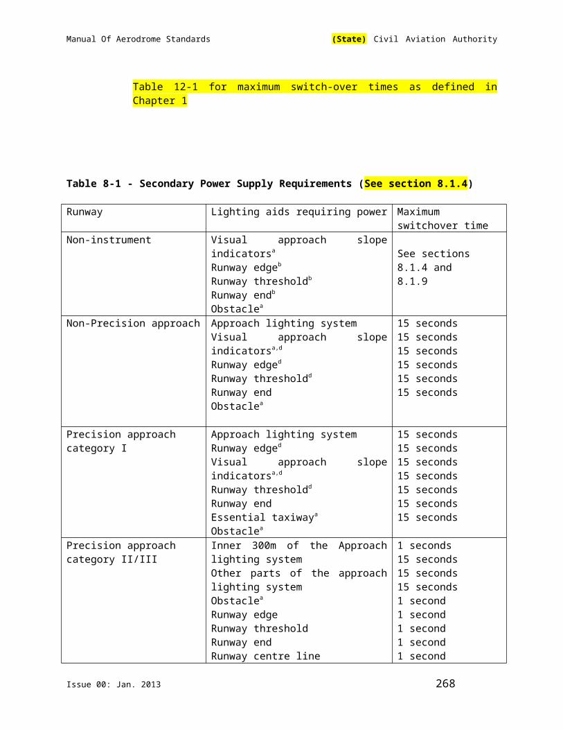
Manual Of Aerodrome Standards (State) Civil Aviation Authority
(vi) Identify procedures concerning multiple alarms and mutual aid;
(vii) Demonstrate knowledge of the phonetic alphabet;
(viii) Demonstrate the use of all communicationequipment utilized by the fire-fighting service;
(ix) Provide an initial status report on a simulated aircraft accident; and
(x) Demonstrate standard hand signals used to communicate with aircrew personnel as it relates to aircraft fire fighting.
(3) With respect to fire-fighting personnel safety, the candidate shall be able to:
(i) Identify the hazards associated with aircraft fire fighting;
(ii) Identify the hazards associated with aircraft and aircraft systems on personnel;
(iii) Identify potential stress effects on personnel involved in a mass-casualty response;
(iv) Identify the purpose and limitations of protective clothing;
(v) Demonstrate donning protective clothing;
(vi) Demonstrate techniques for action in a fire situation where trapped or disoriented, or when in an
hostile environment;
(vii) Identify the hazards associated with cut-in entries;
(viii) Describe the hazardous respiratory environment encountered in aircraft fire fighting;
(ix) Identify techniques for protection from communicable-disease hazards;
(x) Describe the proper techniques for approaching aircraft while engines are running;
(xi) Identify the purpose of self-contained breathing apparatus (SCBA);
(xii) Identify the components and operation of theSCBA provided;
Issue 00: Jan. 2013 268

Manual Of Aerodrome Standards (State) Civil Aviation Authority
(xiii) Identify the limitations of the SCBA provided;
(xiv) Demonstrate that the SCBA is in a safe operating condition for immediate use;
(xv) Don SCBA equipment while wearing protective clothing;(xvi) blacked out environment
(xvii) change a team member’s exhausted air supply cylinder with and air cylinder;
(xviii) While wearing SCBA equipment, demonstrate those actions necessary in the event of one of the
following emergency situations :
- activation of low-air alarm;
- exhausted air supply;
- regulator malfunction;
- damage to face piece;
- damage to low pressure hose;
- damage to high pressure hose.
(4) With respect to fire behaviour, the candidate shall be able to:
(i) Explain the fire tetrahedron;
(ii) Describe the phases of a fire;
(iii) Describe the main products of combustion;
(iv) Describe the three methods of heat transfer;
(v) Describe the classes of fire and extinguishment methods;
(vi) Define flash point, ignition temperature, flashover rollover, backdraft and explosion; and
(vii) Describe the various aviation fuels' characteristics with respect to fire behaviour and explosion hazard.
(5) With respect to extinguishing agents, the candidate shall be able to:
Issue 00: Jan. 2013 269

Manual Of Aerodrome Standards (State) Civil Aviation Authority
(i) Identify the extinguishing properties of each agent, including advantages and disadvantages;
(ii) Identify those agents used at the aerodrome;
(iii) identify the locations of agents kept in inventory for vehicle resupply
(iv) State the quantity of each agent carried on each vehicle at the airport or aerodrome; and
(v) Identify the preffered agent to use to suppress and extinguish fire in various case scenarios
(6) With respect to portable fire extinguishers, the candidate shall be able to:
(i) Identify the classification of fires as they relate to the use of fire extinguishers;
(ii) Identify each type of portable fire extinguisher by classification and rating;
(iii) Describe the agents' characteristics in the extinguishers used at the aerodrome;
(iv) Identify the limitations and operating characteristics of each type of portable fire extinguisher;
(v) Identify the location of each portable fire extinguisher carried on each AFF vehicle used at the
aerodrome;
(vi) Identify the appropriate extinguisher for a given class of fire from a group of different fire extinguishers;
and
(vii) Operate the appropriate extinguisher on each class of fire.
(7) With respect to fire hoses, nozzles, turrets and other appliances available for fire-fighting, the candidate shall be able to:
(i) Identify the location of each tool and item of equipment used at the aerodrome;
(ii) Identify the hazards associated with the use of each tool and item of equipment used at the aerodrome;
Issue 00: Jan. 2013 270
Manual Of Aerodrome Standards (State) Civil Aviation Authority
(iii) Demonstrate the proper procedures for use of each tool and item of equipment used at the aerodrome;
(iv) Describe the purpose of each hose, nozzle and adapter;
(v) Describe the location of each hose, and adapter used by the fire-fighting unit at the aerodrome;
(vi) Describe the siize and length of each hose carried on each AFF vehicle used at the airport or
aerodrome;
(vii) Demonstrate the proper procedures for use of each hose, nozzle and adapter used at the airport or aerodrome;
(viii) Demonstrate the proper procedure to be used when
advancing hose for fire attack;
(ix) Demonstrate the proper procedure to be used when laying hose to establish re-supply of water;
(x) Identify the primary purpose, agent capacity, water capacity, type of agent carried,agent discharge rate and range, personnel requirement, and response limitation
for each AFF vehicle used at the airport or aerodrome;
(xi) Demonstrate the operation of handlines and vehicle mounted discharge devices; and
(xii) Demonstrate the procedure for resupply using a hydrant, structural vehicles, tank trucks and other vehicle for each AFF vehicle used at the airport or aerodrome
(8) With respect to fire-fighting operations, the candidate shall be able to:
(i) State the objective of aircraft fire fighting and the role of the firefighter in response to an aircraft
emergency;
(ii) Describe fire-fighting tactics and evacuation of occupied aircraft;
(iii) Describe fire-fighting tactics of unoccupied aircraft; (d) Select a strategy and tactics for incident control and
termination;
Issue 00: Jan. 2013 271

Manual Of Aerodrome Standards (State) Civil Aviation Authority
(iv) Select a strategy and tactics for incident control and termination;
(v) Perform fire-fighting tactics;
(vi) Explain the correct procedures for fighting three-dimensional fires;
(vii) Explain the correct procedures for fighting engine fires;
(viii) Describe the correct procedures for securing and maintaining a fire free egress route;
(ix) Describe the proper procedure to use when protecting an aircraft fuselage from fire exposure;
(x) Describe the correct procedures to be used when providing protective streams for personnel;
(xi) Describe the hazards of a brake and wheel fire;
(xii) Describe the correct procedures to be used when fighting a brake and wheel fire;
(xiii) Describe the correct procedures for controlling runoff from fire control operations and fuel spills;
(xiv) Describe the correct procedures to be used to stabilize aircraft wreckage;
(xv) Describe the safety precautions for controlling fuel spills;
(xvi) Describe grounding, bonding and hazards associated with static electricity related to aircraft;
(xvii) Describe the hazards of a hydraulic fire; and
(xviii) Describe the correct procedures to use in the event of fighting a hydraulic fire.
(9) With respect to emergency aircraft evacuation assistance, the candidate shall be able to:
(i) Describe the correct procedures to use to protect evacuation points;
(ii) Identify those openings to use to gain entry for a given aircraft and situation;
Issue 00: Jan. 2013 272

Manual Of Aerodrome Standards (State) Civil Aviation Authority
(iii) Select the tools and equipment to use to gain entry for a given aircraft and situation;
(iv) While wearing full protective clothing, demonstratethe ability to open:
(aa) aircraft doors and exits, or
(bb) equivalent training doors and exits.
(v) Identify potential locations for break-in entry using reference materials, aircraft markings, or general guidelines for a given aircraft; and
(vi) Demonstrate the correct procedures to use for a victim search inside and outside the aircraft.
(10) With respect to aircraft cargo hazards, the candidate shall be able to:
(i) Identify the dangerous goods' classifications;
(ii) Identify the hazards indicated by each label; and
(iii) Identify the emergency procedures to be followed using the reference material in the event of a problem
transporting hazardous materials at the airport or aerodrome.
(11) With respect to live-fire training, in order that the agent is applied with proper technique and the fire extinguished,
the candidate shall be able to:
(i) Extinguish a minimum of 9 m2 fuel fire with a minimum of a 45 kg dry chemical extinguisher;
(ii) Extinguish a minimum of 36 m2 fuel fire with an AFF vehicle hand line and appropriate agent;
(iii) Extinguish a minimum of 400 m2 fuel fire with AFFvehicle turrets and appropriate agent;
(iv) Extinguish a three-dimensional aircraft fuel firewith AFF vehicle hand lines and appropriate agent;
Issue 00: Jan. 2013 273

Manual Of Aerodrome Standards (State) Civil Aviation Authority
(v) Control simulated engine and auxiliary power unit (APU) fires on aircraft with an AFF vehicle hand line or turrets and appropriate agent; and
(vi) Extinguish a simulated tire assembly fire with anAFF vehicle hand line and appropriate agent.
(12) With respect to first aid, the candidate shall be able to:
(i) Identify primary and secondary life-threatening injuries;
(ii) Determine whether or not a victim has an open airway;
(iii) Locate an open airway in a person who is not breathing;
(iv) Recognize types and characteristics of external and internal bleeding;
(v) Demonstrate techniques to control bleeding;
(vi) Perform cardiopulmonary resuscitation;
(vii) Recognize shock;
(viii) Recognize injuries to the skull, spine, chest, and extremities;
(ix) Recognize internal injuries;
(x) Demonstrate procedures for moving patients;
(xi) Treat burns; and
(xii) Demonstrate knowledge concerning triage methodology.
(b) Site-Specific Training
(1) With respect to familiarisation with the aerodrome where the firefighter will be carrying out fire-fighting duties, the
candidate shall be able to:
(i) Describe the runway and taxiway identification system;
(ii) Describe the movement area pavement markings, signs, and lighting;
(iii) Identify the various on-field aircraft navigation aids;
(iv) Cite aerodrome rules and regulations concerning vehicle movement and access;
Issue 00: Jan. 2013 274
Manual Of Aerodrome Standards (State) Civil Aviation Authority
(v) Cite rules and regulations governing aerodrome security;
(vi) Locate a given point at the aerodrome on a grid map, or other standard map;
(vii) Identify terrain features using map symbols;
(viii) Identify and locate all emergency access roads and standard routes across the movement area;
(ix) Identify and locate all points giving access to the airside from non-operational areas;
(x) Identify and locate all points giving access to portions of the critical fire-fighting access area, located
outside the aerodrome perimeter;
(xi) Identify installations and features in the critical fire- fighting access area that present a hazard to
vehicle response;
(xii) Identify installations and terrain features in the critical fire-fighting access area that limit vehicle response
capability;
(xiii) Identify the direction of travel of fuel in a simulated leak in the fuel distribution system applicable to the aerodrome;
(xiv) Demonstrate the operation of fuel system valves and pumps to control the flow of fuel within the system applicable to the aerodrome;
(xv) Identify hazardous materials that are frequently stored or used on the aerodrome property; and
(xvi) Identify elements of the aerodrome and surrounding water distribution system.
(2) With respect to familiarisation with the types of aircraft regularly operating at the airport or aerodrome where the firefighter
will be carrying out fire-fighting duties, the candidate shall be able to:
(i) Identify the types of aircraft regularly operating at their airport or aerodrome;
(ii) Identify the categories of aircraft propulsion systems;
(iii) Use the correct terms to describe major aircraft structural components;
Issue 00: Jan. 2013 275

Manual Of Aerodrome Standards (State) Civil Aviation Authority
(iv) Describe the types of batteries found on aircraftand their associated hazards;
(v) Identify the general location of portable fire extinguishers;
(vi) Describe the materials used in aircraft construction;
(vii) Explain the differences in aircraft construction as it relates to fire fighting;
(viii) Use an aircraft crash chart to identify and describe the location of normal and emergency exits, fuel tanks, passenger and crew compartments, oil tanks, hydraulic reservoirs, oxygen tanks, batteries, and break-in points
for given aircraft;
(ix) Use an aircraft crash chart to describe passenger, crew and fuel capacities for a given aircraft;
(x) Identify a flight data recorder and cockpit voice recorder;
(xi) Locate normal entry doors, emergency exit openings and evacuation slides for a given aircraft;
(xii) Describe the opening of all doors and compartments for a given aircraft;
(xiii) Describe the operation of evacuation slides and/or other emergency egress systems for a given aircraft;
(xiv) Identify aircrew and passenger locations for a given aircraft;
(xv) Indicate the type of fuel used and location of fuel tanks for a given aircraft;
(xvi) Locate break-in points for a given aircraft;
(xvii) Locate the batteries for a given aircraft;
(xviii) Locate key components of the fuel, oxygen, hydraulic, electrical, fire protection, APU, brake, wheel
systems, and pressurization systems for a given aircraft; and
(xix) Describe aircraft hazards that may be unique or unusual for a given aircraft.
Issue 00: Jan. 2013 276

Manual Of Aerodrome Standards (State) Civil Aviation Authority
Note: Examples of unusual hazards include military aircraft equipped with ejection seats, tanks containing pesticides on crop-spraying aircraft, and
aircraft equipped with additional fuel tanks for ferry purposes.
(3) With respect to familiarisation with firefighter duties under the Aerodrome Emergency Response Plan where the fire-fighter will be carrying out fire-fighting duties, the candidate shall be able to:
(i) Describe each emergency listed in the plan;
(ii) Describe the chain of command and authority, and identify the individuals associated with
each position requiring a response from the aircraft fire- fighting service for each emergency listed in the plan;
(iii) If applicable, describe the procedure for the change of command during any phase of the emergency requiring a response from the aircraft fire-fighting service for each emergency listed in the plan;
(iv) With reference to the emergency response plan, identify other agencies involved in the plan requiring a
response from the aircraft fire-fighting service, and describe their respective roles and responsibilities for each emergency listed in the plan; and
(v) Demonstrate knowledge of their individual role and duties during regular exercises under the plan.
(c) Additional Training
(1) Low-Visibility Training
At an aerodrome certified for low-visibility operations for Category III approaches, firefighters shall practice the use of low-visibility equipment provided at that aerodrome in simulated Category III low-visibility conditions, and demonstrate the ability to:
(i) Locate a simulated accident site;
(ii) Navigate the aircraft fire-fighting vehicle to the simulated accident site; and
(iii) Negotiate terrain and obstacles with the AFF vehicle.
(2) Command and Control Training
Issue 00: Jan. 2013 277
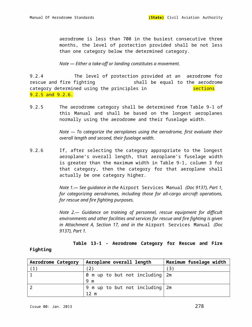
Manual Of Aerodrome Standards (State) Civil Aviation Authority
Where a firefighter is assigned operational command and control responsibilities for the aircraft fire-fighting service, training in command and control functions shall be provided to enable that fire-fighter to:
(i) Assess tactical priorities;
(ii) Control and manage a fire stream;
(iii) Control and manage resources;
(iv) Select, employ and direct a defensive strategy;
(v) Assess fire-ground factors;
(vi) Direct apparatus placement; and
(vii) Explain command procedures.
(3) Recurrent Training
General
Recurrent training shall be provided to enable each firefighter to maintain the level of proficiency established in this standard. Except for live-fire training, every firefighter must complete training in each element of the standards at least once every three years.
(4) Live-Fire Training
Live-fire drill training shall be provided to all fire-fighting personnel every 12 months as follows:
(i) A live-fire drill shall simulate a realistic fire-fighting situation, and be of sufficient size and intensity to provide a challenge to the firefighter in relation to the equipment used;
(ii) The conditions simulated in a live-fire drill shall emulate the type of fire which could be encountered on a
typical aircraft at the aerodrome;
(iii) During the drill, each firefighter shall demonstrate the control and extinguishment of a simulated aircraft
fire using:
(a) Handlines and or turrets using an AFF vehicle of a type used at the aerodrome, and
Issue 00: Jan. 2013 278
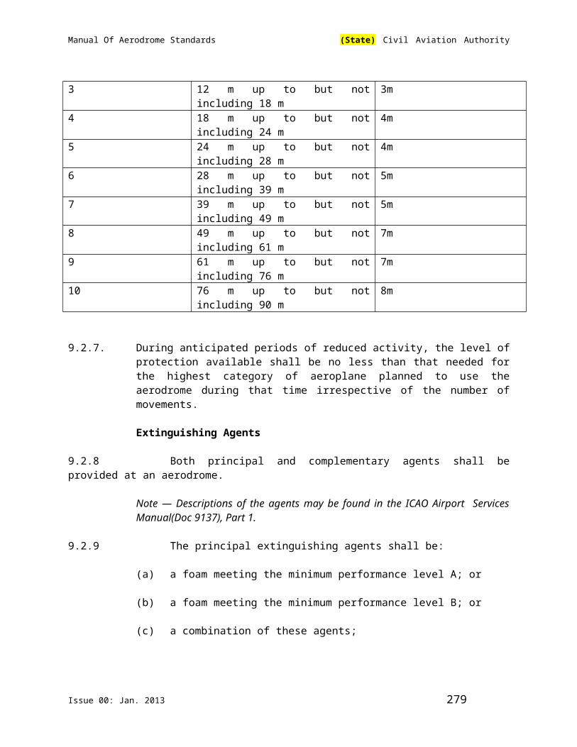
Manual Of Aerodrome Standards (State) Civil Aviation Authority
(b) Fire-fighting streams to protect firefighters and aircraft occupants using either handlines
or turrets.
Note: It is intended that the live-fire drill will provide an opportunity for the fire-fighting team to become familiar with the use of all fire
extinguishment equipment that will be used in the event of an accident. If possible, a simulated evacuation of aircraft occupants will help in creating a realistic situation.
2.5.3 Left Blank Intentionally
2.5.4 Firefighter Qualifications
2.5.4.1 No aerodrome operator shall permit a person to act and no person shall act as an aircraft firefighter at an aerodrome unless the person
has, within the previous 12 months, successfully completed the training specified in this Manual.
2.5.4.2 The aerodrome operator shall:
(a) maintain, for each aircraft firefighter, a training record containing, as a minimum , the information specified below:
(1) the name of the individual being trained;
(2) the date of training;
(3) the place where training is received;
(4) the subjects covered and course methodology;
(5) the climatic conditions, in the case of practical training;
(6) the duration of training;
(7) any instructor comments;
(8) the performance evaluation;
(9) the name of the instructor; and
(10) the signature of the student.
(b) preserve the training record for three years after the aircraft firefighter leaves the service of the aerodrome; and
Issue 00: Jan. 2013 279

Manual Of Aerodrome Standards (State) Civil Aviation Authority
(c) at the request of the Authority, provide the Authority with a copy of the training record.
2.6 Response readiness
2.6.1 Personnel Readiness
The aerodrome operator shall ensure that, during the hours of operation of its aircraft fire-fighting service, of the fire- fighting personnel required to be available, the number of personnel capable of immediate response is sufficient to meet the requirements of the response test referred to in this regulation.
2.6.2 Response Test
2.6.2.1 The aerodrome operator shall carry out a response test to evaluate the response time and effectiveness of the aircraft fire- fighting service required to be maintained during the hours of operation specified every 12 months; and at any time at the request of the Authority, where the Authority has reasonable grounds to believe that the aircraft fire-fighting service at the aerodrome does not meet the requirements of this regulations.
2.6.2.2 The aerodrome operator shall give the Authority at least 30 days written notice of the date on which a response test is to be carried out.
2.6.2.3 The aerodrome operator shall provide the Authority with a copy of the results of a response test within 14 days after the date of the test.
2.6.2.4 A response test at an aerodrome has a satisfactory result if within three minutes after an alarm is sounded, aircraft fire- fighting vehicles in a number sufficient for applying the principal extinguishing agent at 50 per cent of the total discharge capacity required are dispatched from their assigned position and, under optimum surface and visibility conditions at the aerodrome, reach any point of each operational runway;
2.6.2.5 The aerodrome operator shall record the results of a response test and shall preserve the records for two years after the date of the test.
2.6.2.6 If a response test does not have a satisfactory result, the aerodrome operator shall:
Issue 00: Jan. 2013 280

Manual Of Aerodrome Standards (State) Civil Aviation Authority
(1) within six hours after the test, identify the deficiencies that caused the result and notify the appropriate air traffic control unit or any
other flight information unit of the critical category for fire fighting that corresponds to the level of service that can be provided, for publication in a NOTAM; and
(2) within seven days after the test, if any deficiency is not corrected, submit a plan to the Authority specifying the measures
necessary to obtain a satisfactory result and the dates by which they must be taken, which shall be as early as practicable given the circumstances.
2.6.2.7 The aerodrome operator shall implement the submitted plan by the dates specified in the plan.
2.6.3 Left Blank Intentionally
.
CHAPTER 3. AERODROME WILDLIFE PLANNING AND MANAGEMENT
3.1 Application
3.1.1 This chapter applies to aerodromes :
(a) for which in accordance with (State) civil aviation regulations, certification is required;
(b) that have a waste disposal facility within 13km of the geometric centre of the aerodrome;
(c) that had an incident where a turbine-powered aircraft collided with wildlife other than a bird and suffered damage, collided with more than one bird or ingested a bird through an engine; or
(d) where the presence of wildlife hazards, including those referred to in 3.1.1(f) has been observed in an aerodrome flight pattern or movement area. 3.2.4 applies to all aerodromes.
Issue 00: Jan. 2013 281

Manual Of Aerodrome Standards (State) Civil Aviation Authority
(f) The wildlife hazards referred to in this chapter include, in the following descending order of priority with respect to risk, the following hazards:
(1) deer; (2) geese; (3) gulls; (4) hawks; (5) ducks; (6) coyotes; (7) owls; (8) rock doves and pigeons; (9) bald and golden eagles; (10) sandhill cranes; (11) sparrows and snow buntings; (12) shorebirds; (13) blackbirds and starlings; (14) crows and ravens; (15) swallows;
(g) The list of wildlife hazards referred to subsection (f) above is not intended to be exhaustive.
3.2 Wildlife Strikes
3.2.1 The aerodrome operator shall keep records of all wildlife strikes at the aerodrome, including those reported by:
(a) pilots;
(b) ground personnel; and
(c) aircraft maintenance personnel when they identify damage to an aircraft as having been caused by a wildlife strike.
3.2.2 Wildlife remains that are found within 60 meters of a runway or an airside pavement area are presumed to be a wildlife strike unless another cause of death is identified.
3.2.3 The aerodrome operator shall submit a written and dated report to theAuthority using the ICAO IBIS form :
(a) for each wildlife strike, within 30 days of its occurrence;
(b) for all wildlife strikes that occur in a calendar year, on/before
January 31st of the following calendar year.
Issue 00: Jan. 2013 282

Manual Of Aerodrome Standards (State) Civil Aviation Authority
3.3. Risk Analysis
3.3.1 The following constitutes the information to be collected by the operator of an aerodrome:
(a) wildlife strike data;
Note: When reporting a wildlife strike, the form specified by the Authority shall be used. Any information that the operator of an airport has that is outlined on that form should be included.
(b) aircraft movement statistics;
(c) aircraft types; and
(d) ecological studies and wildlife inventories.
Note: An Airport Wildlife Management Plan template may be used to assist operators with the layout of risk assessments and management plans.
3.3.2 The aerodrome operator shall, after consultation with a representative of the operators in respect of an aircraft, air operators and private operators that
use the aerodrome, conduct a risk analysis that evaluates the collected information;
3.3.3 The risk analysis shall be in writing and include:
(a) an analysis of the risks associated with the wildlife hazards, including those referred to in III; and
(b) the measures that are necessary to manage or remove the hazards or to manage or mitigate the risks.
3.3.4 The aerodrome operator shall, at the request of the Authority, make the risk analysis available for inspection.
3.4 Aerodrome Wildlife Management Plan
3.4.1 General
3.4.1.1 The operator shall, in developing an airport wildlife management plan, use the guidance material (Advisory Circular No. XCAA- AC-ARD012),
that may be provided by the Authority.
Issue 00: Jan. 2013 283

Manual Of Aerodrome Standards (State) Civil Aviation Authority
3.4.1.2 The operator shall submit the airport wildlife management plan in the form of a manual and in duplicate to the Authority.
3.4.1.3 The aerodrome operator shall submit the plan to the Authority, on request by the Authority, in accordance with the requirements of paragraph 3.4.1.2.
3.4.1.4 The aerodrome operator shall keep a copy of the plan at the aerodrome and it shall, on request by the Authority, be made available to the Authority.
3.4.1.5 The aerodrome operator shall implement the plan.
3.4.1.6 The aerodrome operator shall review the plan every two years.
3.4.1.7 The aerodrome operator shall amend the plan and submit the amended plan to the Authority within 30 days of the amendment if:
(a) the amendment is necessary as a result of the review conducted under 3.4.1.6 above;
(b) an incident has occurred in which a turbine-powered aircraft collided with wildlife other than a bird and suffered damage,
collided with more than one bird or ingested a bird through an engine;
(c) a variation in the presence of wildlife hazards, including those referred to in 3.1.1(f), has been observed in an aerodrome flight pattern or
movement area; or
(d) there has been a change:
(1) in the wildlife management procedures or in the methods used to manage or mitigate wildlife hazards;
(2) in the types of aircraft at the aerodrome; or
(3) in the types of aircraft operations at the aerodrome.
3.4.2 Content
3.4.2.1 An aerodrome wildlife management plan shall:
(a) identify and describe the risks associated with all wildlife hazards, including those referred to in 3.1.1(f), at or near the aerodrome that might affect the safe operation of aircraft, including the proximity of any waste disposal facility or migration route affecting wildlife populations near the aerodrome;
Issue 00: Jan. 2013 284

Manual Of Aerodrome Standards (State) Civil Aviation Authority
(b) specify the particular measures that are used by the aerodrome operator to manage or mitigate the risks;
(c) identify and describe the actions that are used by the aerodrome operator to satisfy the requirements set out below:
(1) the identification of the species of any wildlife struck by aircraft;
(2) the regular maintenance of wildlife management logs indicatingmanagement activities, environmental changes; wildlife interactions and animal remains identified by species; and
(3) the evaluation of habitats, land uses and food sources, located at or near the airport, that might attract wildlife which may affect the
safe operation of the airport including, if needed, arrangements for assessments, studies and monitoring.
(d) set out a policy for the management of aerodrome habitats that might attract wildlife;
(e) set out a policy that prohibits the feeding of wildlife and the exposure of food wastes;
(f) set out a procedure to ensure that all endangered or protected wildlife at the aerodrome are inventoried;
(g) identify the role of the personnel and agencies involved in wildlife management issues and provide the contact
numbers for each; and
(h) provide details of any wildlife hazard awareness program.
3.5 Training
3.5.1 The aerodrome operator shall:
(a) provide training for any person who has duties in respect of the aerodrome wildlife management plan at least once every three
years regarding their assigned duties and the matters set out below;
(1) nature and extent of the wildlife management problem;
(2) regulations, standards and guidance material related to airport wildlife management programs;
Issue 00: Jan. 2013 285

Manual Of Aerodrome Standards (State) Civil Aviation Authority
(3) bird ecology and biology;
(3) bird identification, including the use of field guides;
(5) mammal ecology and biology;
(6) mammal identification, including the use of field guides;
(7) rare and endangered species and species of special concern, including related regulations and policies;
(8) habitat management;
(9) off-airport land use issues;
(10) active wildlife control measures;
(11) wildlife removal techniques;
(12) firearm safety;
(13) wildlife management planning; and
(14) development of awareness programs
(b) ensure that any person who has duties in respect of the aerodrome wildlife management plan holds any required
firearm permit.
3.5.2 The aerodrome operator shall maintain a record of each person's training for a period of ten years and provide the Authority with a copy of any record,
if requested.
3.6 Communication and Alerting Procedure
The communication and alerting procedure to be used in order to alert pilots as soon as possible of the wildlife hazards at the airport and associated risks may include:
(a) where the aerodrome has air traffic services (ATS), bilateral radio communications or broadcast of airport advisories;
(b) if an immediate alert is required, direct radio contact can be used, when available;
Issue 00: Jan. 2013 286
Manual Of Aerodrome Standards (State) Civil Aviation Authority
(c) publication of a NOTAM in respect of the airport, whether in combination or not with the procedure referred to in paragraph
(a) or (b)
Issue 00: Jan. 2013 287

Manual Of Aerodrome Standards (State) Civil Aviation Authority
PART IV HELIPORT
Issue 00: Jan. 2013 288

Manual Of Aerodrome Standards (State) Civil Aviation Authority
CHAPTER 1. INTRODUCTION
Introductory Note — This chapter contains Standards and Recommended Practices that prescribe the physical characteristics and obstacle limitation surfaces to be provided for at heliports, and certain facilities and technical services normally provided at a heliport. It is not intended that these specifications limit or regulate the operation of an aircraft.
The specifications in this section modify or complement those in previous sections which, where appropriate, are also applicable to heliports. In other words, where a particular issue is a subject of a specification in this section that specification will supersede any other specification on that particular issue in previous sections. Throughout this section the term “heliport” is used; however, it is intended that these specifications also apply to areas for the exclusive use of helicopters at an aerodrome primarily meant for the use of aeroplanes.
When designing a heliport, the critical design helicopter, having the largest set of dimensions and the greatest maximium take-off mass (MTOM) the heliport is intended to serve, would need to be considered.
It is to be noted that provisions for helicopter flight operations are contained in ICAO Annex 6, Part III.
1.1 Definitions
When the following terms are used, they have the meanings given below. Chapter 1 of this manual contains definitions for those terms which are used in both preceeding sections and this section.
Accuracy. A degree of conformance between the estimated or measured value and the true value.
Note.— For measured positional data the accuracy is normally expressed in terms of a distance from a stated position within which there is a defined confidence of the true position falling.
Air taxiway. A defined path on the surface established for the air taxiing of helicopters.
Air transit route. A defined route for the air transiting of helicopters.
Calendar. Discrete temporal reference system that provides the basis for defining temporal position to a resolution of one day (ISO 19108*).
Cyclic redundancy Check A mathematical algorithm applied to the digital expression of data that provides a level of assurance against loss or alteration of data.
Issue 00: Jan. 2013 289

Manual Of Aerodrome Standards (State) Civil Aviation Authority
Data quality. A degree or level of confidence that the data provided meets the requirements of the data user in terms of accuracy, resolution and integrity.
Datum. Any quantity or set of quantities that may serve as a reference or basis for the calculation of other quantities (ISO 19104**).
Declared distances — heliports.
(a) Take-off distance available(TODAH). The length of the final approach and take-off area (FATO) plus the length of helicopter clearway (if provided) declared available and suitable for helicopters to complete the take-off.
(b) Rejected take-off distance available (RTODAH). The length of the final approach and take-off area (FATO) declared available and suitable for helicopters operated in performance class 1 to complete a rejected take-off.
(c) Landing distance available (LDAH). The length of the final approach and take-off area (FATO) plus any additional area declared available and suitable for helicopters to complete the landing manoeuvre from a defined height.
Dynamic load-bearing surface. A surface capable of supporting the loads generated by helicopter
conducting an emergency touchdown on it.
Elevated heliport. A heliport located on a raised structure on land.
Ellipsoid height The height related to the reference ellipsoid, measured along the(Geodetic height). ellipsoidal outer normal through the point in question.
Final approach and A defined area over which the final phase of the approachtake-off area (FATO). manoeuvre to hover or landing is completed and from which the
take-off manoeuvre is commenced. Where the FATO is to be used by helicopters operated in performance class 1, the defined area includes the rejected take-off area available.
Geodetic datum. A minimum set of parameters required to define location and orientation of the local reference system with respect to the global reference system/frame.
Geoid. The equipotential surface in the gravity field of the Earth which coincides with the undisturbed mean sea level (MSL) extended continuously through the continents.
Issue 00: Jan. 2013 290
Manual Of Aerodrome Standards (State) Civil Aviation Authority
Note.— The geoid is irregular in shape because of local gravitational disturbances (wind tides, salinity, current, etc.) and the direction of gravity is perpendicular to the geoid at every point.
Geoid undulation. The distance of the geoid above (positive) or below (negative) the mathematical reference ellipsoid.
Note.— In respect to the World Geodetic System — 1984 (WGS-84) defined ellipsoid, the difference between the WGS- 84 ellipsoidal height and orthometric height represents WGS-84 geoid undulation.
Gregorian calendar. Calendar in general use; first introduced in 1582 to define a year that more closely approximates the tropical year than the Julian calendar (ISO 19108***)
Note.— In the Gregorian calendar, common years have 365 days and leap years 366 days divided into twelve sequential months.
Helicopter air taxiway. A defined path on the surface established for the air taxiing of helicopters.
Helicopter clearway. A defined area on the ground or water under the control of the appropriate authority, selected and/ or prepared as a suitable area over which a helicopter operated in performance class 1 may accelerate and achieve a specific height.
Helicopter ground taxiway. A ground taxiway intended for the ground movement of wheeled
undercarriage helicopters.
Helicopter stand. An aircraft stand which provides for parking a helicopter andwhere ground taxi operations are completed or where the helicopter touches down and lifts off for air taxi operations.
Helideck. A heliport located on an offshore structure such as an exploration or production platform used for the exploitation of oil or gas.
Heliport. An aerodrome or a defined area on a structure intended to be used wholly or in part for the arrival, departure and surface movement of helicopters.
Integrity A degree of assurance that an aeronautical data and its value has(aeronautical data). not been lost nor altered since the data origination or authorized
amendment.
Obstacle. All fixed (whether temporary or permanent) and mobile objects, or parts thereof, that : (a) are located on an area intended for the surface movement of
aircraft; or
Issue 00: Jan. 2013 291

Manual Of Aerodrome Standards (State) Civil Aviation Authority
(b) extend above a defined surface intended to protect aircraft in flight; or
(c) stand outside those defined surfaces and that have been assessed as being a hazard to air navigation.
Orthometric height. Height of a point related to the geoid, generally presented as an MSL elevation.
Protection area. An area within a taxi-route and around a helicopter stand which provides separation from objects, the FATO, other taxi-routes and helicopter stands, for safe manoeuvring of helicopters.
Rejected take-off area. A defined area on a heliport suitable for helicopters operating in performance class 1 to complete a rejected take-off.
Safety area. A defined area on a heliport surrounding the FATO which is free of obstacles, other than those required for air navigation purposes, and intended to reduce the risk of damage to helicopters accidentally diverging from the FATO.
Shipboard heliport. A heliport located on a ship that may be purpose or non-purpose-built. A purpose-built shipboard heliport is one designed specifically for helicopter operations. A non-purpose-built shipboard heliport is one that utilizes an area of the ship that is capable of supporting a helicopter but not designed specifically for that task.
Static load-bearing surface. A surface capable of supporting the mass of a helicopter situated upon it.
Station declination. An alignment variation between the zero degree radial of a VOR and true north, determined at the time the VOR station is calibrated.
Surface level heliport. A heliport located on the ground or on the water.
Taxi-route. A defined path established for the movement of helicopters from one part of a heliport to another. A taxi-route includes a helicopter air or ground taxiway which is centred on the taxi-route.
Touchdown and lift-off area (TLOF). A load bearing area on which a helicopter may touchdown or lift
off.
Winching area. An area provided for the transfer by helicopter of personnel or stores to or from a ship.
*ISO Standard 19108, Geographic information – Temporal schema**ISO Standard 19104, Geographic information – Terminology
Issue 00: Jan. 2013 292

Manual Of Aerodrome Standards (State) Civil Aviation Authority
***ISO Standard 19108, Geographic information – Temporal schema
1.2 Applicability
Note — The dimensions discussed in this Part are based on consideration of single-main-rotor helicopters. For tandem-rotor helicopters the heliport design will be based on a case-by-case review of the specific models using the basic requirement for a safety area and protection areas specified in this Chapter.
1.2 .1 The interpretation of some of the specifications here expressly requires the exercising of discretion, the taking of a decision or the performance of a function by the appropriate Authority. In other specifications, the expression appropriate authority does not actually appear although its inclusion is implied In both cases, the responsibility for whatever determination or action necessary shall rest with the XCAA.
1.1.2 The specifications in this shall apply to all heliports intended to be used by helicopters in (State). The specifications of previous Partshall apply, where appropriate, to these heliports as well.
1.2.3 Wherever a colour is referred to in this section, the specifications for that colour earlier given shall apply.
1.3 Common reference systems
1.3.1 Horizontal reference system
1.3.1.1 World Geodetic System — 1984 (WGS-84) shall be used as the horizontal (geodetic) reference system. Reported aeronautical geographical coordinates (indicating latitude and longitude) shall be expressed in terms of the WGS-84 geodetic reference datum.
Note.— Comprehensive guidance material concerning WGS-84 is contained in the World Geodetic System — 1984(WGS-84) Manual (Doc 9674).
1.3.2 Vertical reference system
1.3.2.1 Mean sea level (MSL) datum, which gives the relationship of gravity-related height (elevation) to a surface known as the geoid, shall be used as the vertical reference system.
Note 1.— The geoid globally most closely approximates MSL. It is defined as the equipotential surface in the gravity field of the Earth which coincides with the undisturbed MSL extended continuously through the continents.
Note 2.— Gravity-related heights (elevations) are also referred to as orthometric heights while distances of points above the ellipsoid are referred to as ellipsoidal heights.
Issue 00: Jan. 2013 293

Manual Of Aerodrome Standards (State) Civil Aviation Authority
1.3.3 Temporal reference system
1.3.3.1 The Gregorian calendar and Coordinated Universal Time (UTC) shall be used as the temporal reference system.
1.3.3.2 When a different temporal reference system is used, this shall be indicated in GEN 2.1.2 of the Aeronautical Information Publication (AIP).
Issue 00: Jan. 2013 294

Manual Of Aerodrome Standards (State) Civil Aviation Authority
CHAPTER 2. HELIPORT DATA
2.1 Aeronautical Data
2.1.1 Determination and reporting of heliport related aeronautical data shall be in accordance with the accuracy and integrity requirements set forth in tables A1- 1 to A1-5 contained in Appendix 1of ICAO Annex 14, Vol. II, while taking into account the established quality system procedures. Accuracy requirements for aeronautical data are based upon a 95 per cent confidence level and in that respect, three types of positional data shall be identified: surveyed points (e.g. FATO threshold), calculated points (mathematical calculations from the known surveyed points of points in space, fixes) and declared points (e.g. flight information region boundary points).
Note. — Specifications governing the quality system are given in ICAO Annex 15, Chapter 3.
2.1.2 Operators shall ensure that integrity of aeronautical data is maintained throughout the data process from survey/origin to the next intended user. Aeronautical data integrity requirements shall be based upon the potential risk resulting from the corruption of data and upon the use to which the data item is put. Consequently, the following classification and data integrity level shall apply:
(a) critical data, integrity level 1 x 10⁻⁸: there is a high probability when using corrupted critical data that the continued safe flight and landing of an aircraft would be severely at risk with the potential for catastrophe;
(b) essential data, integrity level 1 x10⁻⁵ : there is a low probability when using corrupted essential data that the continued safe flight and landing of an aircraft would be severely at risk with the potential for catastrophe; and
(c) routine data, integrity level 1 x10⁻³: there is a very low probability when using corrupted routine data that the continued safe flight and landing of an aircraft would be severely at risk with the potential for catastrophe.
2.1.3 Protection of electronic aeronautical data while stored or in transit shall be totally monitored by the cyclic redundancy check (CRC). To achieve protection of the integrity level of critical and essential aeronautical data as classified in section 2.1.2 above, a 32 or 24 bit CRC algorithm shall apply respectively.
2.1.4 Recommendation. — To achieve protection of the integrity level of routine aeronautical data as classified in .2.1.2 above, a 16 bit CRC algorithm should apply.
Note — Guidance material on the aeronautical data quality requirements (accuracy, resolution, integrity, protection and traceability) is contained in the World Geodetic System — 1984 (WGS-84) Manual (Doc 9674). Supporting
Issue 00: Jan. 2013 295

Manual Of Aerodrome Standards (State) Civil Aviation Authority
material in respect of the provisions of Appendix 1 related to accuracy and integrity of aeronautical data, is contained in RTCA Document DO-201A and European Organisation for Civil Aviation Equipment (EUROCAE) Document ED-77, entitled “Industry Requirements for Aeronautical Information”.
2.1.5 Geographical coordinates indicating latitude and longitude shall be determined and reported to the aeronautical information services authority in terms of the World Geodetic System — 1984 (WGS-84) geodetic reference datum, identifying those geographical coordinates which have been transformed into WGS-84 coordinates by mathematical means and whose accuracy of original field work does not meet the requirements in ICAO Annex 14 Vol. II Appendix 1,Table A1-1
2.1.6 The order of accuracy of the field work shall be such that the resulting operational navigation data for the phases of flight will be within the maximum deviations, with respect to an appropriate reference frame as indicated in tables contain in ICAO Annex 14 Vol. II Appendix 1.
2.1.7 In addition to the elevation (referenced to mean sea level) of the specific surveyed ground positions at heliports, geoid undulation (referenced to the WGS-84 ellipsoid) for those positions as indicated in ICAO Annex 14 Vol. II Appendix 1, shall be determined and reported to the aeronautical information services authority.
Note 1.— An appropriate reference frame is that which enables WGS-84 to be realised on a given heliport and with respect to which all coordinate data are related.
Note 2.— Specifications governing the publication of WGS-84 coordinates are given in Annex 4, Chapter 2, and Annex 15,Chapter 3.
2.2 Heliport Reference Point
2.2.1 A heliport reference point shall be established for a heliport not co-located with an aerodrome.
Note.— When the heliport is co-located with an aerodrome ,the established aerodrome reference point serves both aerodrome and heliport.
2.2.2 The heliport reference point shall be located near the initial or planned geometric centre of the heliport and shall normally remain where first established.
2.2.3 The position of the heliport reference point shall be measured and reported to the Aeronautical Information Services in degrees, minutes and seconds.
2.3 Heliport Elevation
Issue 00: Jan. 2013 296

Manual Of Aerodrome Standards (State) Civil Aviation Authority
2.3.1 The heliport elevation and geoid undulation at the heliport elevation position shall be measured and reported to the Aeronautical Information Services to the accuracy of one-half metre or foot.
2.3.2 For a heliport used by international civil aviation, the elevation of the touchdown and lift-off area and/or the elevation and geoid undulation of each threshold of the final approach and take-off area (where appropriate) shall be measured and reported to the Aeronautical Information Services to the accuracy of:
— one-half metre or foot for non-precision approaches; and
— one-quarter metre or foot for precision approaches.
Note.— Geoid undulation must be measured in accordance with the appropriatesystem of coordinates.
2.4 Heliport Dimensions and Related Information
2.4.1 The following data shall be measured or described, as appropriate, for each facility provided on a heliport:
(a) heliport type — surface-level, elevated or helideck;
(b) touchdown and lift-off area — dimensions to the nearest metre or foot, slope, surface type, bearing strength in tonnes (1000 kg);
(c) final approach and take-off area — type of FATO, true bearing to one-hundredth of a degree, designation number (where appropriate), length, width to the nearest meter or foot, slope, surface type;
(d) safety area — length, width and surface type;
(e) helicopter ground taxiway, air taxiway and air transit route — designation, width, surface type;
(f) apron — surface type, helicopter stands;
(g) clearway — length, ground profile;
(h) visual aids for approach procedures, marking and lighting of FATO, TLOF, taxiways and aprons, and
(i) distances to the nearest meter or foot of localizer and glide path elements comprising an instrument landing system (ILS) or azimuth and elevation antenna of microwave landing system (MLS) in relation to the associated TLOF or FATO extremities.
2.4.2 The geographical coordinates of the geometric centre of the touchdown and lift-off area and/or of each threshold of the final approach and take-off area (where
Issue 00: Jan. 2013 297

Manual Of Aerodrome Standards (State) Civil Aviation Authority
appropriate) shall be measured and reported to the Aeronautical Information Services in degrees, minutes, seconds and hundredths of seconds.
2.4.3 The geographical coordinates of appropriate centre line points of helicopter ground taxiways, air taxiways and air transit routes shall be measured and reported to the Aeronautical Information Services in degrees, minutes, seconds and hundredths of seconds.
2.4.4 The geographical coordinates of each helicopter stand shall be measured and reported to the Aeronautical Information Services in degrees, minutes, seconds and hundredths of seconds.
2.4.5 The geographical coordinates of obstacles in Area 2 (the part within the heliport boundary) and in Area 3 shall be measured and reported to the aeronautical information services in degrees, minutes, seconds and tenths of seconds. In addition, the top elevation, type, marking and lighting (if any) of obstacles shall be reported to the Aeronautical Information Services.
Note 1.— See Annex 15, Appendix 8, for graphical illustrations of obstacle data collection surfaces and criteria used to identify obstacles in Areas 2 and 3.
Note 2.— ICAO Annex 14 Vol. II Appendix 1 provides requirements for obstacle data determination in Areas 2 and 3.
Note 3. — Implementation of Annex 15, section 10.6.1.2, concerning the availability, as of 18 November 2010, of obstacle data according to Area 2 and Area 3 specifications would be facilitated by appropriate advanced planning for the collection and processing of such data.
2.5 Declared distances
The following distances to the nearest metre or foot shall be declared, where relevant, for a heliport:
(a) take-off distance available;
(b) rejected take-off distance available; and
(c) landing distance available.
2.6 Co-ordination between Aeronautical Information Services and Heliport Authorities
2.6.1 To ensure that Aeronautical Information Services units obtain information to enable them to provide up-to-date pre-flight information and to meet the need for in-flight information, arrangements shall be made between Aeronautical Information Services and Heliport Authorities responsible for Heliport Services to report to the responsible Aeronautical Information Services, with a minimum of delay:
Issue 00: Jan. 2013 298
Manual Of Aerodrome Standards (State) Civil Aviation Authority
(a) information on heliport conditions;
(b) the operational status of associated facilities, services and navigation aids within their area of responsibility;
(c) any other information considered to be of operational significance.
2.6.2 Before introducing changes to the air navigation system, due account shall be taken by the services responsible for such changes of the time needed by the Aeronautical Information Services for the preparation, production and issue of relevant material for promulgation. To ensure timely provision of the information to the Aeronautical Information Services, close co-ordination between those services concerned is therefore required.
2.6.3 Of a particular importance are changes to aeronautical information that affect charts and/or computer based navigation systems which qualify to be notified by the Aeronautical Information Regulation and Control (AIRAC) system as specified in Annex 15 Chapter 6 and appendix 4. The predetermined, internationally agreed AIRAC effective dates in addition to 14 days postage time shall be observed by the responsible Heliport Services when submitting the raw information/data to Aeronautical Information Services.
2.6.4 The heliport services responsible for the provision of raw aeronautical information/data to the Aeronautical Information Services shall do that while taking into account accuracy and integrity requirements for aeronautical data as specified in ICAO Annex 14, Vol. II, Appendix 1.
Note 1 — Specifications for the issue of a NOTAM are contained in ICAO Annex 15, Chapter 5, Appendices 6 and 2 respectively.
Note 2 — The AIRAC information is distributed by the AIS at least 42 days in advance of the AIRAC effective dates with the objective of reaching recipients at least 28 days in advance of the effective date.
Note 3 — The schedule of the predetermined internationally agreed AIRAC common effective dates at intervals of 28 days, including 19 November 1997 and guidance for the AIRAC use are contained in the Aeronautical Information Services Manual (Doc 8126, Chapter 2, 2.6).
Issue 00: Jan. 2013 299

Manual Of Aerodrome Standards (State) Civil Aviation Authority
CHAPTER 3. PHYSICAL CHARACTERISTICS
3.1 Surface-Level Heliports
Note 1.— The following specifications are for land-based heliports only. Where a water heliport is being considered, the appropriate authority may establish suitable criteria.
Note 2.— The dimensions of the taxi-routes and helicopter stands include a protection area.
Final Approach and Take-Off Areas
3.1.1 A surface-level heliport shall be provided with at least one final approach and take-off area(FATO).
Note. —A FATO may be located on or near a runway strip or taxiway strip.
3.1.2 A FATO shall be obstacle free.
3.1.3 The dimensions of a FATO shall be:
(a) where intended to be used by helicopters operated in performance class 1, as prescribed in the helicopter flight manual(HFM) except that, in the absence of width specifications, the width shall be not less than the greatest over-all dimension(D) of the largest helicopter the FATO is intended to serve;
(b) where intended to be used by helicopters operated in performance class 2 and 3, of sufficient size and shape to contain an area within which can be drawn a circle of diameter not less than:
1) D of the largest helicopter when the maximum take-off mass (MTOM) of helicopters the FATO is intended to serve is more than 3 175 kg;
2) 0.83 D of the largest helicopter when the MTOM of helicopters the FATO is intended to serve is 3 175 kg or less.
Note.— Where the term FATO is not used in the HFM, the minimum landing/take-off area specified in the HFM for the appropriate flight profile is used.
3.1.4 Recommendation. — where intended to be used by helicopters in performance class 2 and 3 with MTOM of 3175kg or less, the FATO should be of sufficient size and shape to contain an area within which can be drawn a circle of diameter not less than 1D.
Issue 00: Jan. 2013 300
Manual Of Aerodrome Standards (State) Civil Aviation Authority
Note. — Local conditions, such as elevation and temperature, may need to be considered when determining the size of a FATO. Guidance is given in the Heliport Manual(Doc 9261).
3.1.5 The mean slope in any direction on the FATO shall not exceed 3 per cent. No portion of a FATO shall have a local slope exceeding:
(a) 5 per cent where the heliport is intended to be used by helicopters operated in performance class 1; and
(b) 7 per cent where the heliport is intended to be used by helicopters operated in performance class 2 and 3.
3.1.6 The surface of the FATO shall:
(a) be resistant to the effects of rotor downwash;
(b) be free of irregularities that would adversely affect the take-off or landing of helicopters; and
(c) have bearing strength sufficient to accommodate a rejected take-off by helicopters operated in performance class 1.
3.1.7 The surface of a FATO surrounding a touchdown and lift-off area (TLOF) intended for use by helicopters operated in performance classes 2 and 3 shall be static load-bearing.
3.1.8 Recommendation — The FATO should provide ground effect.
Helicopter Clearways
3.1.9 When it is necessary to provide a helicopter clearway, it shall be located beyond the upwind end of the rejected take-off area available.
3.1.10 Recommendation — The width of a helicopter clearway should not be less than that of the associated safety area.
3.1.11 Recommendation — The ground in a helicopter clearway should not project above a plane having an upward slope of 3 per cent, the lower limit of this plane being a horizontal line which is located on the periphery of the FATO.
3.1.12 Recommendation — An object situated on a helicopter clearway which may endanger helicopters in the air should be regarded as an obstacle and should be removed.
Touchdown and Lift-Off Areas
3.1.13 At least one touchdown and lift-off area shall be provided at a heliport.
Issue 00: Jan. 2013 301
Manual Of Aerodrome Standards (State) Civil Aviation Authority
Note 1. — The touchdown and lift-off area may or may not be located within the FATO.
Note 2.— Additional TLOFs may be collocated with helicopter stands.
3.1.14 The touchdown and lift-off area (TLOF) shall be of sufficient size to contain a circle of diameter of at least 0.83D of the largest helicopter the area is intended to serve.
Note. — A touchdown and lift-off area may be any shape.
3.1.15 Slopes on a touchdown and lift-off area shall be sufficient to prevent accumulation of water on the surface of the area, but shall not exceed 2 per cent in any direction.
3.1.16 Where the TLOF is within the FATO, the TLOF shall be dynamic load-bearing.
3.1.17 Where a TLOF is collocated with a helicopter stand, the TLOF shall be static load-bearing and be capable of withstanding the traffic of helicopters that the area is intended to serve.
3.1.18 Where the TLOF is within the FATO, the centre of the TLOF shall be located not less than 0.5 D from the edge of the FATO.
Safety Areas
3.1.19 A FATO shall be surrounded by a safety area which need not be solid.
3.1.20 A safety area surrounding a FATO intended to be used by helicopter operated in performance class 1 in Visual Meteorological Conditions (VMC) shall extend outwards from the periphery of the FATO for a distance of at least 3 m or 0.25D, whichever is greater, of the largest helicopter the FATO is intended to serve and:
(a) each external side of the safety area shall be at least 2 D where the FATO is quadrilateral; or
(b) the outer diameter of the safety area shall be at least 2 D where the FATO is circular.
3.1.21 A safety area surrounding a FATO intended to be used by helicopters operated in performance class 2 or 3 in visual meteorological conditions (VMC) shall extend outwards from the periphery of the FATO for a distance of at least 3 m or0.5 D, whichever is greater, of the largest helicopter the FATO is intended to serve and:
(a) each external side of the safety area shall be at least 2 D where the FATO is quadrilateral; or
(b) the outer diameter of the safety area shall be at least 2 D where the FATO is circular.
Issue 00: Jan. 2013 302
Manual Of Aerodrome Standards (State) Civil Aviation Authority
3.1.22 There shall be a protected side slope rising at 45 degrees from the edge of the safety area to a distance of 10 m, whose surface shall not be penetrated by obstacles, except that when obstacles are located to one side of the FATO only, they may be permitted to penetrate the side slope surface.
IV. 3.1.23 A safety area surrounding a FATO intended to be used by helicopter operations in Instrument Meteorological Conditions (IMC) shall extend:
(a) laterally to a distance of at least 45 m on each side of the centre line; and
(b) longitudinally to a distance of at least 60 m beyond the ends of the FATO.
Note. — See Figure 3-1 of ICAO Annex 14, Vol. II
3.1.24 No fixed object shall be permitted on a safety area, except for frangible objects, which, because of their function, must be located on the area. No mobile object shall be permitted on a safety area during helicopter operations.
3.1.25 Objects whose functions require them to be located on the safety area shall not exceed a height of 25 cm when located along the edge of the FATO nor penetrate a plane originating at a height of 25 cm above the edge of the FATO and sloping upwards and outwards from the edge of the FATO at a gradient of 5 per cent.
3.1.26 Recommendation.— In the case of a FATO of diameter less than 1 D, the maximum height of the objects whose functions require them to be located on the safety area should not exceed a height of 5 cm.
3.1.27 The surface of the safety area, when solid, shall not exceed an upward slope of 4 per cent outwards from the edge of the FATO.
3.1.28 Where applicable, the surface of the safety area shall be treated to prevent flying debris caused by rotor downwash.
3.1.29 The surface of the safety area abutting the FATO shall be continuous with the FATO.
Helicopter Ground Taxiways and ground taxi-routes
Note 1. —A helicopter ground taxiway is intended to permit the surface movement of a wheeled helicopter under its own power.
Note 2.—The following specifications are intended for the safety of simultaneous operations during the manoeuvring of helicopters. However, the wind velocity induced by the rotor downwash might have to be considered.
Note 3. —When a taxiway is intended for use by aeroplanes and helicopters, the provisions for taxiways and helicopter ground taxiways will be taken into consideration and the more stringent requirements will be applied.
Issue 00: Jan. 2013 303
Manual Of Aerodrome Standards (State) Civil Aviation Authority
3.1.30 The width of a helicopter ground taxiway shall not be less than 1.5 times the largest width of the undercarriage (UCW) of the helicopters the ground taxiway is intended to serve (see ICAO Annex 14 Vol II Figure 3-2).
3.1.31 The longitudinal slope of a helicopter ground taxiway shall not exceed 3 per cent.
3.1.32 A helicopter ground taxiway shall be static load-bearing and be capable of withstanding the traffic of the helicopters the helicopter ground taxiway is intended to serve.
3.1.33 A helicopter ground taxiway shall be centred on a ground taxi-route.
3.1.34 A helicopter ground taxi-route shall extend symmetrically on each side of the centre line for at least 0.75 times the largest overall width of the helicopters it is intended to serve.
3.1.35 No objects shall be permitted on a helicopter ground taxi-route, except for frangible objects, which, because of their function, must be located there.
3.1.36 The helicopter ground taxiway and the ground taxi-route shall provide rapid drainage but the helicopter ground taxiway transverse slope shall not exceed 2 per cent.
3.1.37 The surface of a helicopter ground taxi-route shall be resistant to the effect of rotor downwash.
Helicopter air taxiways and air taxi-routes
Note. — A helicopter air taxiway is intended to permit the movement of a helicopter above the surface at a height normally associated with ground effect and at groundspeed less than 37 km/h (20 kt).
3.1.38 The width of an helicopter air taxiway shall be at least two times the largest width of the undercarriage(UCW) of the helicopters that the air taxiway is intended to serve (see ICAO Annex 14 Vol. II, Figure 3-3).
3.1.39 The surface of a helicopter air taxiway shall be suitable for emergency landings.
3.1.40 Recommendation —The surface of a helicopter air taxiway should be static load-bearing.
3.1.41 Recommendation — The transverse slope of the surface of a helicopter air taxiway should not exceed 10 per cent and the longitudinal slope should not exceed 7 per cent. In any event, the slopes should not exceed the slope landing limitations of the helicopters the air taxiway is intended to serve.
3.1.42 A helicopter air taxiway shall be centred on an air taxi-route.
Issue 00: Jan. 2013 304
Manual Of Aerodrome Standards (State) Civil Aviation Authority
3.1.43 A helicopter air taxi-route shall extend symmetrically on each side of the centre line for a distance at least equal to the largest overall width of the helicopters it is intended to serve.
3.1.44 No objects shall be permitted on an air taxi-route, except for frangible objects, which, because of their function, must be located thereon.
3.1.45 The surface of an air taxi-route shall be resistant to the effect of rotor downwash.
3.1.46 The surface of an air taxi-route shall provide ground effect.
Air Transit Route
Note. — An air transit route is intended to permit the movement of a helicopter above the surface, normally at heights not above 30 m (100ft) above ground level and at ground speeds exceeding 37 km/h (20 kt).
3.1.47 The width of an air transit route shall not be less than:
(a) 7.0 times the largest overall width of the helicopters the air transit route is intended for use by day only; and
(b) 10.0 times the largest overall width of the helicopters the air transit route is intended to serve when the air transit routes is intended for use at night;
3.1.48 Any variation in the direction of the centre line of an air transit route shall not exceed 120°and be designed so as not to necessitate a turn of radius less than 270 m.
Note — It is intended that air transit routes be selected so as to permit authoritative or one-engine-inoperative landings such that, as a minimum requirement, injury to persons on the ground or water, or damage to property are minimised.
Aprons
3.1.49 The slope in any direction on a helicopter stand shall not exceed 2 per cent.
3.1.50 A helicopter stand shall be of sufficient size to contain a circle of diameter of at least 1.2 D of the largest helicopter the stand is intended to serve.
3.1.51 If a helicopter stand is used for taxi-through, the minimum width of the stand and associated protection area shall be that of the taxi-route (see ICAO Annex 14 Vol. II, Figure 3-4).
3.1.52 When a helicopter stand is used for turning, the minimum dimension of the stand and protection area shall be not less than 2 D (see ICAO Annex 14 Vol. II, Figure 3-5).
Issue 00: Jan. 2013 305

Manual Of Aerodrome Standards (State) Civil Aviation Authority
3.1.53 When a helicopter stand is used for turning, it shall be surrounded by a protection area which extends for a distance of 0.4 D from the edge of the helicopter stand.
3.1.54 For simultaneous operations, the protection area of helicopter stands and their associated taxi-routes shall not overlap (see ICAO Annex 14 Vol. II, Figure 3-6).
Note.— Where non-simultaneous operations are envisaged, the protection area of helicopter stands and their associated taxi-routes may overlap (see ICAO Annex 14 Vol. II, Figure 3-7).
3.1.55 When intended to be used for ground taxi operations by wheeled helicopters, the dimensions of a helicopter stand shall take into account the minimum turn radius of wheeled helicopters the stand is intended to serve.
3.1.56 A helicopter stand and associated protection area intended to be used for air taxiing shall provide ground effect.
3.1.57 No fixed objects shall be permitted on a helicopter stand and the associated protection area.
3.1.58 The central zone of the stand shall be capable of withstanding the traffic of helicopters that it is intended to serve and have a static load-bearing area:
(a) of diameter not less than 0.83 D of the largest helicopter it is intended to serve; or
(b) for a helicopter stand intended to be used for ground taxi-through, the same width as the ground taxiway.
Note.— For a helicopter stand intended to be used for turning on the ground, the dimension of the central zone may need to be increased.
Location of a Final Approach and Take-Off area in Relation to a Runway or Taxiway.
3.1.59 Where a FATO is located near a runway or taxiway, and simultaneous VMC operations are planned, the separation distance between the edge of a runway or taxiway and the edge of a FATO shall not be less than the appropriate dimension in Table IV-1.
3.1.60 Recommendation —A FATO should not be located:
(a) near taxiway intersections or holding points where jet engine efflux is likely to cause high turbulence; or
(b) near areas where aeroplane vortex wake generation is likely to exist.
Table IV-1. FATO Minimum Separation Distance
If aeroplane mass and/or helicopter mass Distance between FATO edge and
Issue 00: Jan. 2013 306

Manual Of Aerodrome Standards (State) Civil Aviation Authority
are runway edge or taxiway edgeup to but not including 3,175 kg 60m3,175 kg up to but not including 5,760 kg 120m5,760 kg up to but not including 100,000 kg 180m100,000 kg and over 250 m
3.2 Elevated Heliports
Note 1.— The dimensions of the taxi-routes and helicopter stands include a protection area.
Note 2 — Guidance on structural design for elevated heliports is given in the Heliport Manual (Doc 9261).
3.2.1 In the case of elevated heliports, design considerations of the different elements of the heliport shall take into account additional loading resulting from the presence of personnel, fog, freight, refuelling, fire fighting equipment, etc
Final Approach and Take-Off areas and Touchdown and Lift-Off Areas
Note. —On elevated heliports it is presumed that the FATO and the TLOF will be coincidental.
3.2.2 An elevated heliport shall be provided with at least one FATO.
3.2.3 A FATO shall be obstacle free.
3.2.4 The dimensions of the FATO shall be:
(a) where intended to be used by helicopters operated in performance class1, as prescribed in the helicopter flight manual(HFM) except that, in the absence of width specifications, the width shall be not less than 1D of the largest helicopter the FATO is intended to serve;
(b) where intended to be used by helicopter operated in performance class 2or 3, of sufficient size and shape to contain an area within which can be drawn a circle of diameter not less than:
1) 1 D of the largest helicopter when the MTOM of helicopters the FATO is intended to serve is more than 3 175 kg;
2) 0.83 D of the largest helicopter when the MTOM of helicopters the FATO is intended to serve is 3 175 kg or less.
3.2.5 Recommendation.— Where intended to be used by helicopters operated in performance class 2 or 3 with MTOM of 3 175 kg or less, the FATO should be of sufficient size and shape to contain an area within which can be drawn a circle of diameter not less than 1 D.
Issue 00: Jan. 2013 307
Manual Of Aerodrome Standards (State) Civil Aviation Authority
Note.— Local conditions, such as elevation and temperature, may need to be considered when determining the size of a FATO. Guidance is given in the Heliport Manual (Doc 9261).
3.2.6 Slopes on a FATO at an elevated heliport shall be sufficient to prevent accumulation of water on the surface of the area, but shall not exceed 2 per cent in any direction.
3.2.7 The FATO shall be dynamic load-bearing.
3.2.8 The surface of the FATO shall be:
(a) resistant to the effects of rotor downwash; and
(b) free of irregularities that would adversely affect the take-off or landing of helicopters.
3.2.9 Recommendation.— The FATO should provide ground effect.
Helicopter clearways
3.2.10 When a helicopter clearway is provided, it shall be located beyond the end of the rejected take-off area available.
3.2.11 Recommendation.— The width of a helicopter clearway should not be less than that of the associated safety area.
3.2.12 Recommendation.— When solid, the surface of the helicopter clearway should not project above a plane having an upward slope of 3 per cent, the lower limit of this plane being a horizontal line which is located on the periphery of theFATO.
3.2.13 Recommendation.— An object situated on a helicopter clearway which may endanger helicopters in the air should be regarded as an obstacle and should be removed.
Touchdown and lift-off areas
3.2.14 One TLOF shall be coincidental with the FATO.
Note.— Additional TLOFs may be collocated with helicopter stands.
3.2.15 For a TLOF coincidental with the FATO, the dimensions and the characteristics of the TLOF shall be the same as those of the FATO.
3.2.16 When the TLOF is collocated with a helicopter stand, the TLOF shall be of sufficient size to contain a circle of diameter of at least 0.83 D of the largest helicopter the area is intended to serve.
Issue 00: Jan. 2013 308

Manual Of Aerodrome Standards (State) Civil Aviation Authority
3.2.17 Slopes on a TLOF collocated with a helicopter stand shall be sufficient to prevent accumulation of water on the surface of the area, but shall not exceed 2 per cent in any direction.
3.2.18 When the TLOF is collocated with a helicopter stand and intended to be used by ground taxiing helicopters only, the TLOF shall at least be static load-bearing and be capable of withstanding the traffic of the helicopters the area is intended to serve.
3.2.19 When the TLOF is collocated with a helicopter stand and intended to be used by air taxiing helicopters, the TLOF shall have a dynamic load-bearing area.
Safety Areas
3.2.20 The FATO shall be surrounded by a safety area which need not be solid.
3.2.21 A safety area surrounding a FATO intended to be used by helicopters operated in performance class 1 in visual meteorological conditions (VMC) shall extend outwards from the periphery of the FATO for a distance of at least 3 m or 0.25 D, whichever is greater, of the largest helicopter the FATO is intended to serve and:.
(a) each external side of the safety area shall be at least 2 D where the FATO is quadrilateral; or
(b) the outer diameter of the safety area shall be at least 2 D where the FATO is circular.
3.2.22 A safety area surrounding a FATO intended to be used by helicopters operated in performance class 2 or 3 in visual meteorological conditions (VMC) shall extend outwards from the periphery of the FATO for a distance of at least 3 m or 0.5 D, whichever is the greater, of the largest helicopter the FATO is intended to serve and:
(a) each external side of the safety area shall be at least 2 D where the FATO is quadrilateral; or
(b) the outer diameter of the safety area shall be at least 2 D where the FATO is circular.
3.2.23 There shall be a protected side slope rising at 45 degrees from the edge of the safety area to a distance of 10 m, whose surface shall not be penetrated by obstacles, except that when obstacles are located to one side of the FATO only, they may be permitted to penetrate the side slope surface.
3.2.24 No fixed object shall be permitted on a safety area, except for frangible objects, which, because of their function, must be located on the area. No mobile object shall be permitted on a safety area during helicopter operations.
3.2.25 Objects whose function require them to be located on the safety area shall not exceed a height of 25 cm when located along the edge of the FATO nor
Issue 00: Jan. 2013 309

Manual Of Aerodrome Standards (State) Civil Aviation Authority
penetrate a plane originating at a height of 25 cm above the edge of the FATO and sloping upwards and outwards from the edge of the FATO at a gradient of 5 per cent.
3.2.26 Recommendation.— In the case of a FATO of diameter less than 1 D, the maximum height of the objects whose functions require them to be located on the safety area should not exceed a height of 5 cm.
3.2.27 The surface of the safety area, when solid, shall not exceed an upward slope of 4 per cent outwards from the edge of the FATO.
3.2.28 Where applicable, the surface of the safety area shall be prepared in a manner to prevent flying debris caused by rotor downwash.
3.2.29 The surface of the safety area abutting the FATO shall be continuous with the FATO.
Helicopter ground taxiways and ground taxi-routes
Note.— The following specifications are intended for the safety of simultaneous operations during the manoeuvring of helicopters. However, the wind velocity induced by the rotor downwash might have to be considered.
3.2.30 The width of a helicopter ground taxiway shall not be less than 2 times the largest width of the undercarriage (UCW) of the helicopters the ground taxiway is intended to serve.
3.2.31 The longitudinal slope of a helicopter ground taxiway shall not exceed 3 per cent.
3.2.32 A helicopter ground taxiway shall be static load-bearing and be capable of withstanding the traffic of the helicopters the helicopter ground taxiway is intended to serve.
3.2.33 A helicopter ground taxiway shall be centred on a ground taxi-route.
3.2.34 A helicopter ground taxi-route shall extend symmetrically on each side of the centre line to a distance not less than the largest overall width of the helicopters it is intended to serve.
3.2.35 No objects shall be permitted on a helicopter ground taxi-route, except for frangible objects, which, because of their function, must be located there.
3.2.36 The helicopter ground taxiway and the ground taxi-route shall provide rapid drainage but the helicopter ground taxiway transverse slope shall not exceed 2 per cent.
3.2.37 The surface of a helicopter ground taxi-route shall be resistant to the effect of rotor downwash.
Helicopter air taxiways and air taxi-routes
Issue 00: Jan. 2013 310

Manual Of Aerodrome Standards (State) Civil Aviation Authority
Note.— A helicopter air taxiway is intended to permit the movement of a helicopter above the surface at a height normally associated with ground effect and at ground speed less than 37 km/h (20 kt).
3.2.38 The width of a helicopter air taxiway shall be at least three times the largest width of the undercarriage (UCW) of the helicopters the air taxiway is intended to serve.
3.2.39 The surface of a helicopter air taxiway shall be dynamic load-bearing.
3.2.40 The transverse slope of the surface of a helicopter air taxiway shall not exceed 2 per cent and the longitudinal slope shall not exceed 7 per cent. In any event, the slopes shall not exceed the slope landing limitations of the helicopters the airtaxiway is intended to serve.
3.2.41 A helicopter air taxiway shall be centred on an air taxi-route.
3.2.42 A helicopter air taxi-route shall extend symmetrically on each side of the centre line to a distance not less than the largest overall width of the helicopters it is intended to serve.
3.2.43 No objects shall be permitted on an air taxi-route, except for frangible objects, which, because of their function, must be located thereon.
3.2.44 The surface of an air taxi-route shall be resistant to the effect of rotor downwash.
3.2.45 The surface of an air taxi-route shall provide ground effect.
Aprons
3.2.46 The slope in any direction on a helicopter stand shall not exceed 2 per cent.
3.2.47 A helicopter stand shall be of sufficient size to contain a circle of diameter of at least 1.2 D of the largest helicopters the stand is intended to serve.
3.2.48 If a helicopter stand is used for taxi-through, the minimum width of the stand and associated protection area shall be that of the taxi-route.
3.2.49 When a helicopter stand is used for turning, the minimum dimension of the stand and protection area shall be not less than 2 D.
3.2.50 When a helicopter stand is used for turning, it shall be surrounded by a protection area which extends for a distance of 0.4 D from the edge of the helicopter stand.
3.2.51 For simultaneous operations, the protection area of helicopter stands and their associated taxi-routes shall not overlap.
Issue 00: Jan. 2013 311
Manual Of Aerodrome Standards (State) Civil Aviation Authority
Note.— Where non-simultaneous operations are envisaged, the protection area of helicopter stands and their associated taxi-routes may overlap.
3.2.52 When intended to be used for ground taxi operations by wheeled helicopters, the dimensions of a helicopter stand shall take into account the minimum turn radius of the wheeled helicopters the stand is intended to serve.
3.2.53 A helicopter stand and associated protection area intended to be used for air taxiing shall provide ground effect.
3.2.54 No fixed objects shall be permitted on a helicopter stand and the associated protection area.
3.2.55 The central zone of the helicopter stand shall be capable of withstanding the traffic of the helicopters it is intended to serve and have a load-bearing area:
(a) of diameter not less than 0.83 D of the largest helicopter it is intended to serve; or
(b) for a helicopter stand intended to be used for ground taxi-through, the same width as the ground taxiway.
3.2.56 The central zone of a helicopter stand intended to be used for ground taxiing only shall be static load-bearing.
3.2.57 The central zone of a helicopter stand intended to be used for air taxiing shall be dynamic load-bearing.
Note.— For a helicopter stand intended to be used for turning on the ground, the dimension of the central zone might have to be increased.
3.3 Helidecks
Note. — The following specifications are for helidecks located on structures engaged in such activities as mineral exploitation, research or construction. See section 3.4 for shipboard heliport provisions.
Final Approach and Take-off Areas and Touchdown and Lift-off Areas
Note — On helidecks it is presumed that the FATO and the TLOF will be coincidental. Guidance on the effects of airflow direction and turbulence, prevailing wind velocity and high temperatures from gas turbine exhausts or flare radiated heat on the location of the FATO is given in the Heliport Manual(Doc. 9261).
3.3.1 The specifications in section 3.3.9 and 3.3.10 shall be applicable for helidecks completed on or after 1 January 2012.
Issue 00: Jan. 2013 312

Manual Of Aerodrome Standards (State) Civil Aviation Authority
3.3.2 A helideck shall be provided with at least one FATO.
3.3.3 A FATO may be any shape but shall be of sufficient size to contain:
(a) for helicopters with an MTOM of more than 3 175 kg, an area within which can be accommodated a circle of diameter not less than 1.0 D of the largest helicopter the helideck is intended to serve; and
(b) for helicopters with an MTOM of 3 175 kg or less, an area within which can be accommodated a circle of diameter not less than 0.83 D of the largest helicopter the helideck is intended to serve.
3.3.4 Recommendation.— For helicopters with an MTOM of 3 175 kg or less, the FATO should be of sufficient size to contain an area within which can be accommodated a circle of diameter not less than 1.0 D of the largest helicopter the helideck is intended to serve.
3.3.5 A FATO shall be dynamic load-bearing.
3.3.6 A FATO shall provide ground effect.
3.3.7 No fixed object shall be permitted around the edge of the FATO except for frangible objects, which, because of their function, must be located thereon.
3.3.8 Objects whose function require them to be located on the edge of the FATO shall not exceed a height of 25 cm, except that in the case of a FATO of diameter less than 1 D, the maximum height of such objects shall not exceed a height of 5 cm.
3.3.9 Objects whose function requires them to be located within the FATO (such as lighting or nets) shall not exceed a height of 2.5 cm. Such objects may be present only if they do not represent a hazard to helicopters.
Note.— Examples of potential hazards include nets or raised fittings on the deck that might induce dynamic rollover for helicopters equipped with skids.
3.3.10 Safety net or safety shelves shall be located around the edge of a helideck but shall not exceed the helideck height.
3.3.11 The surface of the FATO shall be skid-resistant to both helicopters and persons and be sloped to prevent pooling of water.
Note —Guidance on rendering the surface of the FATO skid-resistant is contained in the Heliport Manual(Doc 9261).
3.4 Shipboard Heliports
3.4.1 The specifications in section 3.4.11 shall be applicable to shipboard heliports completed on or after 1 January 2012.
Issue 00: Jan. 2013 313

Manual Of Aerodrome Standards (State) Civil Aviation Authority
3.4.2 When helicopter operating areas are provided in the bow or stern of a ship or are purpose-built above the ship’s structure, they shall be regarded as purpose-built shipboard heliports.
Final approach and take-off areas and touchdown and lift-off areas
Note. — On shipboard heliports, it is presumed that the FATO and the TLOF will be coincidental. Reference to FATO within the shipboard heliport section of this Chapter is assumed to include the TLOF. Guidance on the effects of airflow direction and turbulence, prevailing wind velocity and high temperatures from gas turbine exhausts or flare radiated heat on the location of the FATO is given in the Heliport Manual(Doc 9261)
3.4.3 Shipboard heliports shall be provided with at least one FATO.
3.4.4 A FATO on a shipboard heliport shall be dynamic load-bearing.
3.4.5 The FATO of a shipboard heliport shall provide ground effect.
3.4.6 For purpose-built shipboard heliports provided in a location other than the bow or stern, the FATO shall be of sufficient size to contain a circle with a diameter not less than 1.0 D of the largest helicopter the heliport is intended to serve.
3.4.7 For purpose-built shipboard heliports provided in the bow or stern of a ship, the FATO shall be of sufficient size to:
(a) contain a circle with a diameter not less than 1 D of the largest helicopter the heliport is intended to serve; or
(b) for operations with limited touchdown directions, contain an area within which can be accommodated two opposing arcs of a circle with a diameter not less than 1 D in the helicopter’s longitudinal direction The minimum width of the heliport shall be not less than 0.83 D (see ICAO Annex 14 Vol. II, Figure 3-8).
Note 1 — The ship will need to be manoeuvred to ensure that the relative wind is appropriate to the direction of the helicopter touchdown heading.
Note 2 — The touchdown heading of the helicopter is limited to the angular distance subtended by the 1 D arc headings, minus the angular distance which corresponds to 15 degrees at each end of the arc.
3.4.8 For non-purpose-built shipboard heliports, the FATO shall be of sufficient size to contain a circle with a diameter not less than 1 D of the largest helicopter the helideck is intended to serve.
3.4.9 No fixed object shall be permitted around the edge of the FATO, except for frangible objects, which, because of their function, must be located thereon.
Issue 00: Jan. 2013 314
Manual Of Aerodrome Standards (State) Civil Aviation Authority
3.4.10 Objects whose function require them to be located on the edge of the FATO shall not exceed a height of 25 cm.
3.4.11 Objects whose function requires them to be located within the FATO (such as lighting or nets) shall not exceed a height of 2.5 cm. Such objects may be present only if they do not represent a hazard to helicopters.
3.4.12 The surface of the FATO shall be skid-resistant to both helicopters and persons.
Issue 00: Jan. 2013 315
Manual Of Aerodrome Standards (State) Civil Aviation Authority
CHAPTER 4. OBSTACLE RESTRICTION AND REMOVAL
Note. — The objectives of the specifications in this section are to define the airspace around heliports to be maintained free from obstacles so as to permit the intended helicopter operations at the heliports to be conducted safely and to prevent the heliports becoming unusable by the growth of obstacles around them. This is achieved by establishing a series of obstacle limitation surfaces that define the limits to which objects may project into the airspace.
4.1 Obstacle Limitation Surfaces and Sectors
Approach Surface
4.1.1 Description. An inclined plane or a combination of planes sloping upwards from the end of the safety area and centred on a line passing through the centre of the FATO(See Figure 4-1 in ICAO Annex 14 Vol. II).
4.1.2 Characteristics. The limits of an approach surface shall comprise:
(a) an inner edge horizontal and equal in length to the minimum specified width of the FATO plus the safety area, perpendicular to the centre line of the approach surface and located at the outer edge of the safety area;
(b) two side edges originating at the ends of the inner edge and:
1) for other than a precision approach FATO, diverging uniformly at a specified rate from the vertical plan containing the centre line of the FATO,
2) for a precision approach FATO, diverging uniformly at a specified rate from the vertical plane containing the centre line of the FATO, to a specified height above FATO, and then diverging uniformly at a specified rate to a specified final width and continuing thereafter at that width for the remaining length of the approach surface; and
(c) an outer edge horizontal and perpendicular to the centre line of the approach surface and at a specified height above the elevation of the FATO.
4.1.3 The elevation of the inner edge shall be the elevation of the safety area at the point on the inner edge that is intersected by the centre line of the approach surface.
4.1.4 The slope(s) of the approach surface shall be measured in the vertical plane containing the centre line of the surface.
Issue 00: Jan. 2013 316
Manual Of Aerodrome Standards (State) Civil Aviation Authority
Note . — For heliports used by performance class 2 and 3 helicopters, it is intended that approach paths be selected so as to permit safe forced landing or one-engine-inoperative landings such that, as a minimum requirement, injury to persons on the ground or water or damage to property are minimized. Provisions for forced landing areas are expected to minimize risk of injury to the occupants of the helicopter. The most critical helicopter type for which the heliport is intended and the ambient conditions will be factors in determining the suitability of such areas.
Transitional Surface
4.1.5 Description. A complex surface along the side of the safety area and part of the side of the approach surface, that slopes upwards and outwards to the inner horizontal surface or a predetermined height (See Figure 4-1 in ICAO Annex 14 Vol. II).
4.1.6 Characteristics. The limits of a transitional surface shall comprise:
(a) a lower edge beginning at the intersection of the side of the approach surface with the inner horizontal surface, or beginning at a specified height above the lower edge when an inner horizontal surface is not provided, and extending down the side of the approach surface to the inner edge of the approach surface and from there along the length of the side of the safety area parallel to the centre line of the FATO; and
(b) an upper edge located in the plane of the inner horizontal surface, or at a specified height above the lower edge when an inner horizontal surface is not provided.
4.1.7 The elevation of a point on the lower edge shall be:
(a) along the side of the approach surface - equal to the elevation of the approach surface at that point; and
(b) along the safety area - equal to the elevation of the centre line of the FATO opposite that point.
Note. — As a result of b) the transitional surface along the safety area will be curved if the profile of the FATO is curved, or a plane if the profile is a straight line. The intersection of the transitional surface with the inner horizontal surface, or upper edge when an inner horizontal surface is not provided, will also be a curved or a straight line depending on the profile of the FATO.
4.1.8 The slope of the transitional surface shall be measured in a vertical plane at right angles to the centre line of the FATO.
Inner Horizontal Surface
Note — The intent of the inner horizontal surface is to allow safe visual manoeuvring.
Issue 00: Jan. 2013 317

Manual Of Aerodrome Standards (State) Civil Aviation Authority
4.1.9 Description. A circular surface located in a horizontal plane above a FATO and its environs (See Figure 4-1 in ICAO Annex 14 Vol. II).
4.1.10 Characteristics: The radius of the inner horizontal surface shall be measured from the mid-point of the FATO.
4.1.11 The height of the inner horizontal surface shall be measured above an elevation datum established for such purpose.
Note. —Guidance on determining the elevation datum is contained in the Heliport Manual(Doc 9261).
Conical surface
4.1.12 Description: A surface sloping upwards and outwards from the periphery of the inner horizontal surface, or from the outer limit of the transitional surface if an inner horizontal surface is not provided (See Figure 4-1 in ICAO Annex 14 Vol. II).
4.1.13 Characteristics: The limits of the conical surface shall comprise:
(a) a lower edge coincident with the periphery of the inner horizontal surface, or outer limit of the transitional surface if an inner horizontal surface is not provided; and
(b) an upper edge located at a specified height above the inner horizontal surface, or above the elevation of the lowest end of the FATO if an inner horizontal surface is not provided.
4.1.14 The slope of the conical surface shall be measured above the horizontal.
Take-Off Climb Surface
4.1.15 Description: An inclined plane, a combination of planes or, when a turn is involved, a complex surface sloping upwards from the end of the safety area and centred on a line passing through the centre of the FATO(See Figure 4-1 in ICAO Annex 14 Vol. II).
4.1.16 Characteristics: The limits of a take-off climb surface shall comprise:
(a) an inner edge horizontal and equal in length to the minimum specified width of the FATO plus the safety area, perpendicular to the centre line of the take-off climb surface and located at the outer edge of the safety area or clearway;
(b) two side edges originating at the ends of the inner edge and diverging uniformly at a specified rate from the vertical plane containing the centre line of the FATO and
Issue 00: Jan. 2013 318

Manual Of Aerodrome Standards (State) Civil Aviation Authority
(c) an outer edge horizontal and perpendicular to the centre line of the take-off climb surface and at a specified height above the elevation of the FATO.
4.1.17 The elevation of the inner edge shall be the elevation of the safety area at the point on the inner edge that is intersected by the centre line of the take-off climb surface, except that when a clearway is provided, the elevation shall be equal to the highest point on the ground on the centre line of the clearway.
4.1.18 In the case of a straight take-off climb surface, the slope shall be measured in the vertical plane containing the centre line of the surface.
4.1.19 In the case of a take-off climb surface involving a turn, the surface shall be a complex surface containing the horizontal normals to its centre line and the slope of the centre line shall be the same as that for a straight take-off climb surface. That portion of the surface between the inner edge and 30m above the inner edge shall be straight.
4.1.20 Any variation in the direction of the centre line of a take-off climb surface shall be designed so as not to necessitate a turn of radius less than 270 m.
Note . —For heliports used by performance class 2 and 3 helicopters, it is intended that departure paths be selected so as to permit safe forced landings or one-engine-inoperative landings such that, as a minimum requirement, injury to persons on the ground or water or damage to property are minimized. Provisions for forced landing areas are expected to minimize risk of injury to the occupants of the helicopter. The most critical helicopter type for which the heliport is intended and the ambient conditions will be factors in determining the suitability of such areas.
Obstacle-Free Sector/Surface – Helidecks
4.1.21 Description: A complex surface originating at a reference point on the edge of the FATO of a helideck. In the case of a FATO of less than 1 D, the reference point shall be located not less than 0.5 D from the centre of the FATO.
4.1.22 Characteristics: An obstacle-free sector/surface shall subtend an arc of specified angle.
4.1.23 A helideck obstacle-free sector shall comprise two components, one above and one below helideck level (see ICAO Annex 14 Vol. II, Figure 4-2):
(a) Above helideck level. The surface shall be a horizontal plane level with the elevation of the helideck surface that subtends an arc of at least 210 degrees with the apex located on the periphery of the D reference circle extending outwards to a distance that will allow for an unobstructed
Issue 00: Jan. 2013 319

Manual Of Aerodrome Standards (State) Civil Aviation Authority
departure path appropriate to the helicopter the helideck is intended to serve.
(b) Below helideck level. Within the (minimum) 210-degree arc, the surface shall additionally extend downward from the edge of the FATO below the elevation of the helideck to water level for an arc of not less than 180 degrees that passes through the centre of the FATO and outwards to a distance that will allow for safe clearance from the obstacles below the helideck in the event of an engine failure for the type of helicopter the helideck is intended to serve.
Note.— For both the above obstacle-free sectors for helicopters operated in performance class 1 or 2, the horizontal extent of these distances from the helideck will be compatible with the one-engine-inoperative capability of the helicopter type to be used.
Limited Obstacle Surface – Helidecks
Note – Where obstacles are necessarily located on the structure, a helideck may have a limited obstacle sector.
4.1.24 Description: A complex surface originating at the reference point for the obstacle-free sector and extending over the arc not covered by the obstacle-free sector within which the height of obstacles above the level of the FATO will be prescribed.
4.1.25 Characteristics: The limited obstacle surface shall not subtend an arc greater than 150 degrees. Its dimensions and location shall be as described in Figure 4-3 of ICAO Annex 14 Vol. II.
4.2 Obstacle Limitation Requirements
Note. — The requirements for obstacle limitation surfaces are specified on the basis of the intended use of a FATO, i.e. approach manoeuvre to hover or landing, or take-off manoeuvre and type of approach, and are intended to be applied when such use is made of the FATO. In cases where operations are conducted to or from both directions of a FATO, then the function of certain surfaces may be nullified because of more stringent requirements of another lower surface.
Surface - Level Heliports
4.2.1 The following obstacle limitation surfaces shall be established for a precision approach FATO:
(a) take-off climb surface;
(b) approach surface;
Issue 00: Jan. 2013 320

Manual Of Aerodrome Standards (State) Civil Aviation Authority
(c) transitional surfaces; and
(d) conical surface.
4.2.2 The following obstacle limitation surfaces shall be established for a non-precision approach FATO:
(a) take-off climb surface;
(b) approach surface;
(c) transitional surfaces; and
(d) conical surface if an inner horizontal surface is not provided.
4.2.3 The following obstacle limitation surfaces shall be established for a non-instrument FATO:
(a) take-off climb surface; and
(b) approach surface.
4.2.4 Recommendation—The following obstacle limitation surfaces should be established for a non-precision approach FATO:
(a) inner horizontal surface; and
(b) conical surface.
Note. — An inner horizontal surface may not be required if a straight-in non-precision approach is provided at both ends.
4.2.5 The slopes of the surfaces shall not be greater than, and their other dimensions not less than those specified in Tables 4-l to 4-4 in ICAO Annex 14 Vol. II and shall be located as shown in Figures 4-4 to 4-8 in ICAO Annex 14 Vol. II.
4.2.6 New objects or extensions of existing objects shall not be permitted above any of the surfaces in sections 4.2.1 to 4.2.4 above except when, in the opinion of the Authority, the new object or extension would be shielded by an existing immovable object.
Note —Circumstances in which the shielding principle may reasonably be applied are described in the Airport Services Manual, Part 6(Doc 9137).
4.2.7 Recommendation — Existing objects above any of the surfaces in sections 4.2.1 to 4.2.4 above should, as far as practicable, be removed except when, in the opinion of the Authority, the object is shielded by an existing immovable object or after aeronautical study it is determined that the object would not adversely affect the safety or significantly affect the regularity of operations of helicopters.
Issue 00: Jan. 2013 321

Manual Of Aerodrome Standards (State) Civil Aviation Authority
Note — The application of curved take-off climb surfaces as specified in 4.1.19 may alleviate the problems created by objects infringing these surfaces.
4.2.8 A surface level heliport shall have at least two take-off climb and approach surfaces, separated by not less than 150°.
IV .4.2.9 Recommendation — The number and orientation of take-off climb and approach surfaces should be such that the usability factor of a heliport is not less than 95 per cent for the helicopters the heliport is intended to serve.
Elevated Heliports
4.2.10 The obstacle limitation requirements for elevated heliports shall conform to the requirements for surface level heliports specified in sections 4.2.1 to 4.2.7.
4.2.11 An elevated heliport shall have at least two takeoff climb and approach surfaces separated by not less than 150°.
Helidecks
Note — The following specifications are for helidecks located on a structure and engaged in such activities as mineral exploitation, research, or construction, but excluding heliports on ships.
4.2.12 A helideck shall have an obstacle-free sector.
Note.— A helideck may have a limited obstacle sector (see section 4.1.25).
4.2.13 There shall be no fixed obstacles within the obstacle-free sector above the obstacle-free surface.
4.2.14 In the immediate vicinity of the helideck, obstacle protection for helicopters shall be provided below the heliport level. This protection shall extend over an arc of at least 180° with the origin at the centre of the FATO, with a descending gradient having a ratio of one unit horizontally to five units vertically from the edges of the FATO within the 180° sector. This descending gradient may be reduced to a ratio of one unit horizontally to three within the 180-degree sector for multi-engine helicopters operated in performance class 1 or 2 (see ICAO Annex 14 Vol. II, Figure 4-2).
4.2.15 Where a mobile obstacle or combination of obstacles within the obstacle-free sector is essential for the operation of the installation, the obstacle(s) shall not subtend an arc exceeding 30°, as measured from the centre of the FATO.
4.2.16 Within the 150-degree limited obstacle surface/sector out to a distance of 0.62 D, measured from the centre of the FATO, objects shall not exceed a height of 0.05 D above the FATO. Beyond that arc, out to an overall distance of 0.83 D the limited obstacle surface rises at a rate of one unit vertically for each two units horizontally (see ICAO Annex 14 Vol. II, Figure 4-3).
Issue 00: Jan. 2013 322
Manual Of Aerodrome Standards (State) Civil Aviation Authority
Shipboard Heliports
Purpose-built heliports located forward or aft
4.2.17 The specifications in sections 4.2.20 and 4.2.22 shall be applicable for shipboard heliports completed on or after 1 January 2012.
4.2.18 When helicopter operating areas are provided in the bow or stern of a ship, they shall apply the obstacle criteria given in sections 4.2.12, 4.2.14 and 4.2.16.
Amidships Location
4.2.19 Forward and aft of the FATO shall be two symmetrically located sectors, each covering an arc of 150° with their apexes on the periphery of the FATO D reference circle. Within the area enclosed by these two sectors, there shall be no objects rising above the level of the FATO, except those aids essential for the safe operation of a helicopter and then only up to a maximum height of 25 cm.
4.2.20 Objects whose function requires them to be located within the FATO (such as lighting or nets) shall not exceed a height of 2.5 cm. Such objects may be present only if they do not represent a hazard to helicopters.
Note.— Examples of potential hazards include nets or raised fittings on the deck that might induce dynamic rollover for helicopters equipped with skids.
4.2.21 To provide further protection from obstacles fore and aft of the FATO, rising surfaces with gradients of one unit vertically to five units horizontally shall extend from the entire length of the edges of the two 150° sectors. These surfaces shall extend for a horizontal distance equal to at least 1 D of the largest helicopter the FATO is intended to serve and shall not be penetrated by any obstacle (see ICAO Annex 14 Vol. II. Figure 4-9)
Non-purpose-built heliports
Ship’s Side Location
4.2.22 No objects shall be located within the FATO, except those aids essential for the safe operation of a helicopter (such as nets or lighting) and then only up to a maximum height of 2.5 cm. Such objects shall be present only if they do not represent a hazard to helicopters.
4.2.23 From the fore and aft mid-points of the D reference circle, an area shall extend to the ship’s rail to a fore and aft distance of 1.5 times the diameter of the FATO, located symmetrically about the athwartships bisector of the reference circle. Within this sector there shall be no objects rising above the level of the FATO, except those aids essential to the safe operation of the helicopter and then only up to a maximum height of 25 cm (see ICAO Annex 14 Vol. II, Figure 4-10).
Issue 00: Jan. 2013 323

Manual Of Aerodrome Standards (State) Civil Aviation Authority
4.2.24 A horizontal surface shall be provided, at least 0.25 times the diameter of the D reference circle, which shall surround the FATO and the obstacle-free sector, at a height of 0.05 times the diameter of the reference circle, which no object shall penetrate.
Winching areas
4.2.25 An area designated for winching on-board ships shall comprise a circular clear zone of diameter 5 m and extending from the perimeter of the clear zone, a concentric manoeuvring zone of diameter 2 D (see ICAO Annex 14 Vol. II, Figure 4-11).
4.2.26 The manoeuvring zone shall comprise 2 areas:
(a) the inner manoeuvring zone extending from the perimeter of the clear zone and of a circle of diameter not less than 1.5 D; and
(b) the outer manoeuvring zone extending from the perimeter of the inner manoeuvring zone and of a circle of diameter not less than 2 D.
4.2.27 Within the clear zone of a designated winching area, no objects shall be located above the level of its surface.
4.2.28 Objects located within the inner manoeuvring zone of a designated winching area shall not exceed a height of 3 m.
4.2.29 Objects located within the outer manoeuvring zone of a designated winching area shall not exceed a height of 6 m.
Table IV–2 Dimensions and Slopes of Obstacle Limitation Surfaces
NON-INSTRUMENT AND NON-PRECISION FATONon-instrument (Visual) FATO Non-precision
(instrument approach) FATOSurface and dimensions
Helicopter performance class1 2 3
APPROACH SURFACEWidth of inner edgeLocation of inner edge
Width of Safety area Boundary
Width of safety area Boundary
First SectionDivergence Day 10% 10% 10% 16%
Night 15% 15% 15% -Length Day 245ma 245ma 245ma 2 500m
Night 245ma 245ma 245ma -Outer width Day 49mb 49mb 49mb 890m
Night 7.35mb 7.35mb 7.35mb -Slope (maximum) 8%a 8%a 8%a 3.33%Second SectionDivergence Day 10% 10% 10% -
Night 15% 15% 15% -
Issue 00: Jan. 2013 324

Manual Of Aerodrome Standards (State) Civil Aviation Authority
Length Day c c c -Night c c c -
Outer width Day d d d -Night d d d -
Slope (maximum) 12.5% 12.5% 12.5% -Third SectionDivergence parallel parallel parallel -Length Day e e e -
Night e e e -Outer width Day d d d -
Night d d d -Slope (maximum) 15% 15% 15% -INNER HORIZONTALHeight - - - 45mRadius - - - 2 000mCONICALSlope - - - 5%Height - - - 55mTRANSITIONALSlope - - - 20%Height - - - 45m
a. Slope and length enables helicopters to decelerate for landing while observing, “avoid” areas.
b. The width of the inner edge shall be added to this dimension.c. Determined by the distance from the inner edge to the point where the divergence
produces a width of 7 rotor diameters for day operations or 10 rotor diameters for night operations.
d. Seven rotor diameters overall width for day operations or 10 rotor diameters overall width for night operations.
e. Determined by the distance from inner edge to where the approach surface reaches a height of 150 m above the elevation of the inner edge.
Table IV – 3 Dimensions and slopes of obstacle limitation surfaces
INSTRUMENT (PRECISION APPROACH) FATO
Surface and Dimensions
30 Approach 60 ApproachHeight above FATO Height above FATO90m(300ft)
60m(200ft)
45m(150ft)
30m(100ft)
90m(300ft)
60m(200ft)
45m(150ft)
30m(100ft)
APPROACH SURFACELength of inner edge
90m 90m 90m 90m 90m 90m 90m 90m
Distance from end of FATO
60m 60m 60m 60m 60m 60m 60m 60m
Divergence each side to
25% 25% 25% 25% 25% 25% 25% 25%
Issue 00: Jan. 2013 325
Manual Of Aerodrome Standards (State) Civil Aviation Authority
height above FATODistance to height above FATO
1745m 1163m 872m 581m 870m 580m 435m 290m
Width at height above FATO
962m 671m 526m 380m 521m 380m 307.5m 235m
Divergence to parallel section
15% 15% 15% 15% 15% 15% 15% 15%
Distance to parallel section
2793m 3763m 4246m 4733m 4250m 4733m 4975m 5217m
Width of parallel section
1800m 1800m 1800m 1800m 1800m 1800m 1800m 1800m
Distance to outer edge
5462m 5074m 4882m 4686m 3380m 3187m 3090m 2993m
Width at outer edge
1800m 1800m 1800m 1800m 1800m 1800m 1800m 1800m
Slope of first section
2.5%(1:40)
2.5%(1:40)
2.5%(1:40)
2.5%(1:40)
5%(1:20)
5%(1:20)
5%(1:20)
5%(1:20)
Length of first section
3000m 3000m 3000m 3000m 1500m 1500m 1500m 1500m
Slope of second section
3%(1:33.3)
3%(1:33.3)
3%(1:33.3)
3%(1:33.3)
6%(1:16.66)
6%(1:16.66)
6%(1:16.66)
6%(1:16.66)
Length of second section
2500m 2500m 2500m 2500m 1250m 1250m 1250m 1250m
Total length of surface
10000m
10000m
10000m 10000m 8500m 8500m 8500m 8500m
CONICAL Slope 5% 5% 5% 5% 5% 5% 5% 5%Height 55m 55m 55m 55m 55m 55m 55m 55mTRANSITIONAL Slope 14.3
%14.3% 14.3% 14.3% 14.3% 14.3% 14.3% 14.3%
Height 45m 45m 45m 45m 45m 45m 45m 45mTable IV–4 Dimensions and slopes of obstacle limitation surfaces
STRAIGHT TAKE -OFFNon-instrument (Visual)
InstrumentSurface and dimensions
Helicopter performance class1 2 3
TAKE OFF CLIMBWidth of inner edge Width of Safety area 90m
Issue 00: Jan. 2013 326
Manual Of Aerodrome Standards (State) Civil Aviation Authority
Location of inner edge Boundary or end of clearway Boundary or end of clearway
First SectionDivergence Day 10% 10% 10% 30%
Night 15% 15% 15% -Length Day a 245mb 245mb 2 850m
Night a 245mb 245mb -Outer width Day c 49md 49md 1 800m
Night c 7.35md 7.35md -Slope (maximum) 4.5%* 8%b 8%b 3.5%Second SectionDivergence Day parallel 10% 10% parallel
Night parallel 15% 15% -Length Day e a a 1 510m
Night e a a -Outer width Day c c c 1 800m
Night c c c -Slope (maximum) 4.5%* 15% 15% 3.5%*Third SectionDivergence - parallel parallel parallelLength Day - e e 7640m
Night - e e -Outer width Day - c c 1800m
Night - c c -Slope (maximum) - 15% 15% 2%
a. Determined by the distance from the inner edge to the point where the divergence produces a width of 7 rotor diameters for day operations or 10 rotor diameters for night operations.
b. Slope and length provides helicopters with an area to accelerate and climb while observing “avoid” areas.
c. Seven rotor diameters overall width for day operations or 10 rotor diameters overall width for night operations.
d. The width of the inner edge shall be added to this dimension.e. Determined by the distance from the inner edge to where the surface reaches a height of
150 m above the elevation of the inner edge.* This slope exceeds the maximum mass one-engine-inoperative climb gradient of many
helicopters which are currently operating.
Table IV-5 Criteria for curved take-off climb/approach area
NON-INSTRUMENT FINAL APPROACH AND TAKE-OFFFacility RequirementDirectional change As required (120º max).Radius of turn on centre line Not less than 270 m
Issue 00: Jan. 2013 327
Manual Of Aerodrome Standards (State) Civil Aviation Authority
Distance to inner gate* (a) For performance class1 helicopters not less than 305 m from the end of the safety area or helicopter clearway.(b) For performance class 2 and 3 helicopters – not less than 370 m from the end of the FATO.
Width of inner gate ― day Width of the inner edge plus 20% of distance to inner gate―night Width of the inner edge plus 30% of distance to inner gate.Width of outer gate ― day Width of inner edge plus 20% of distance to inner gate out to
minimum width of 7 rotor diameters.― night Width of inner edge plus 30% of distance to inner gate out to
a minimum width of 10 rotor diameters.
Elevation of inner and outer Determined but the distance from the gates inner edge and the designated gradient(s).
Slopes As given in Tables IV-2 and IV-4Divergence As given in Tables IV-2 and IV-4Total length of area As given in Tables IV-2 and IV-4
* This is the minimum distance required prior to initiating a turn after take-off or completing a turn in the final phase.
Note— More than one turn may be necessary in the total length of the take-off climb/approach area. The same criteria will apply for each subsequent turn except that the widths of the inner and outer gates will normally be the maximum width of the area.
Issue 00: Jan. 2013 328

Manual Of Aerodrome Standards (State) Civil Aviation Authority
CHAPTER 5. VISUAL AIDS
5.1 Indicators
5.1.1 Wind Direction Indicators
Application
5.1.1 .1 A heliport shall be equipped with at least one wind direction indicator.
Location
5.1.1.2 A wind direction indicator shall be located so as to indicate the wind conditions over the FATO and in such a way as to be free from the effects of airflow disturbances caused by nearby objects or rotor downwash. It shall be visible from a helicopter in flight, in a hover or on the movement area.
5.1.1.3 Recommendation — Where a TLOF may be subject to a disturbed air flow, then additional wind direction indicators located close to the area should be provided to indicate the surface wind on the area.
Note. —Guidance on the location of wind direction indicators is given in the Heliport Manual(Doc 9261).
Characteristics
5.1.1.4 A wind direction indicator shall be constructed so that it gives a clear indication of the direction of the wind and a general indication of the wind speed.
5.1.1.5 Recommendation —An indicator should be a truncated cone made of lightweight fabric and should have the following minimum dimensions:
Surface Level Heliports
Elevated Heliports and Helidecks
Length 2.4m 1.2mDiameter (larger end) 0.6m 0.3mDiameter (smaller end) 0.3m 0.15m
5.1.1.6 Recommendation. — The colour of the wind direction indicator should be so selected as to make it clearly visible and understandable from a height of at least 200 m (650 ft) above the heliport, having regard to background. Where practicable, a single colour, preferably white or orange, should be used. Where a combination of two colours is required to give adequate conspicuity against changing backgrounds, they should preferably be orange and white, red and
Issue 00: Jan. 2013 329

Manual Of Aerodrome Standards (State) Civil Aviation Authority
white, or black and white, and should be arranged in five alternate bands the first and last band being the darker colour.
5.1.1.7 A wind direction indicator at a heliport intended for use at night shall be illuminated.
5.2 Markings and Markers
Note. — See Note I, section 5.2.1.4 concerning improving conspicuity of markings
5.2.1 Winching area Marking
Application
5.2.1.1 Winching area marking should be provided at a winching area (see ICAO Annex 14 Vol. II, Figure 4-11).
Location
5.2.1.2 Winching area marking shall be located so that its centre(s) coincides with the centre of the clear zone of the winching area.
Characteristics
5.2.1.3 Winching area markings shall comprise a winching area clear zone marking and a winching area manoeuvring zone marking.
5.2.1.4 A winching area clear zone marking shall consist of a solid circle of not less than 5 m in diameter and of a conspicuous colour.
5.2.1.5 A winching circle manoeuvring zone shall consist of a broken circle of line of 0.2 m in width and of a diameter not less than 2 D and be marked in a conspicuous colour. Within it “WINCH ONLY” shall be marked to be easily visible to the pilot.
5.2.2 Heliport Identification Marking
Application
5.2.2.1 A heliport identification marking shall be provided at a heliport.
Location
5.2.2.2 A heliport identification marking shall be located within the FATO, at or near the centre of the area or when used in conjunction with runway designation markings at each end of the area.
Characteristics
Issue 00: Jan. 2013 330
Manual Of Aerodrome Standards (State) Civil Aviation Authority
5.2.2.3 A heliport identification marking, except for a heliport at a hospital, shall consist of a letter H, white in colour. The dimensions of the marking shall be no less than those shown in Figure 5-l in ICAO Annex 14 Vol. II and where the marking is used in conjunction with the FATO designation marking specified in section 5.2.5 its dimensions shall be increased by a factor of 3.
5.2.2.4 A heliport identification marking for a heliport at a hospital shall consist of a letter H, red in colour, on a white cross made of squares adjacent to each of the sides of a square containing the H as shown in Figure 5- 1 in ICAO Annex 14 Vol. II.
.5.2.2.5 A heliport identification marking shall be oriented with the cross arm of the H at right angles to the preferred final approach direction. For a helideck the cross arm shall be on or parallel to the bisector of the obstacle-free sector as shown in Figure 5-1 of ICAO Annex 14, Vol. II.
5.2.2.6 Recommendation.— On a helideck, the size of the heliport identification “H” marking should have a height of 4 m with an overall width not exceeding 3 m and a stroke width not exceeding 0.75 m.
5.2.3 Maximum Allowable Mass Marking
Application
5.2.3.1 Recommendation—A maximum allowable mass marking should be displayed at an elevated heliport and at a helideck.
Location
5.2.3.2 Recommendation —A maximum allowable mass marking should be located within the TLOF and so arranged as to be readable from the preferred final approach direction.
Characteristics
5.2.3.3 A maximum allowable mass marking shall consist of a one-, two- or three digit number. The marking shall be expressed in tonnes (1000kg) rounded to the nearest 1000kg followed by a letter “t”.
5.2.3.4 Recommendation.— The allowable mass marking should be expressed to the nearest 100 kg. The marking should be presented to one decimal place and rounded to the nearest 100 kg followed by the letter “t”.
5.2.3.5 Recommendation — The numbers and the letter of the marking should have a colour contrasting with the background and should be in the form and proportion shown in Figure 5-2 of ICAO Annex 14 Vol. II, except that where space is limited, such as on an offshore helideck or shipboard heliport, it may be necessary to reduce the size of the marking to characters with an overall height of not less than 90 cm with a corresponding reduction in the width and thickness of the figures.
Issue 00: Jan. 2013 331

Manual Of Aerodrome Standards (State) Civil Aviation Authority
5.2.4 Maximum allowable D-value marking
Application
5.2.4.1 Recommendation.— The D-value marking should be displayed at an elevated heliport and at a helideck.
Location
5.2.4.2 Recommendation.— A maximum allowable D-value marking should be located within the FATO and so arranged as to be readable from the preferred final approach direction.
Characteristics
5.2.4.3 The D-value shall be marked on the FATO in a contrasting colour to it, preferably white. The D-value shall be rounded to the nearest whole number with 0.5 rounded down, e.g. 19.5 becomes 19 and 19.6 becomes 20.
5.2.5 Final Approach and Take-Off area Marking or Marker
Application
5.2.5.1 FATO marking or markers shall be provided at a surface level heliport on ground where the extent of the FATO is not self-evident.
Location
5.2.5.2 FATO marking or markers shall be located on the boundary of the FATO.
Characteristics
5.2.5.3 FATO marking or markers shall be spaced:
(a) for a square or rectangular area, at equal intervals of not more than 50 m with at least three markings or markers on each side including a
marking or marker at each corner; and
(b) for any other shaped area, including a circular area, at equal intervals of not more than 10 m with a minimum number of five markings or markers.
5.2.5.4 A FATO marking shall be a rectangular stripe with a length of 9 m or one-fifth of the side of the FATO which it defines and a width of 1m. Where a marker is used its characteristics shall conform to those specified in section 5.5.8.3 except that the height of the marker shall not exceed 25 cm above ground level.
5.2.5.5 A FATO marking shall be white.
Issue 00: Jan. 2013 332
Manual Of Aerodrome Standards (State) Civil Aviation Authority
5.2.6 Final Approach and Take-Off area Designation Marking
Application
5.2.6.1 Recommendation —A FATO designation marking should be provided where it is necessary to designate the FATO to the pilot.
5.2.6.2 A FATO designation marking shall be located at the beginning of the final approach and take-off area as shown in Figure 5-3 of ICAO Annex 14 Vol. II
5.2.6.3 A FATO designation marking shall consist of a runway designation marking described in sections 5.2.2.4 and 5.2.2.5 supplemented by an H, specified in section 5.2.2 above, and as shown in Figure 5-3 of ICAO Annex 14 Vol. II.
5.2.7 Aiming Point Marking
Application
5.2.7.1 Recommendation —An aiming point marking should be provided at a heliport where it is necessary for a pilot to make an approach to a particular point before proceeding to the TLOF.
Location
5.2.7.2 The aiming point marking shall be located within the FATO.
Characteristics
5.2.7.3 The aiming point marking shall be an equilateral triangle with the bisector of one of the angles aligned with the preferred approach direction. The marking shall consist of continuous white lines and the dimensions of the marking shall conform to those shown in Figure 5-4 of ICAO Annex 14 Vol. II
5.2.8 Touchdown and Lift-Off area Marking
Application
5.2.8.1 TLOF marking shall be provided on a heliport if the perimeter of the TLOF is not self-evident.
Location
5.2.8.2 The TLOF marking shall be located along the perimeter of the TLOF.
Characteristics
5.2.8.3 A TLOF marking shall consist of a continuous white line with a width of at least 30 cm.
Issue 00: Jan. 2013 333
Manual Of Aerodrome Standards (State) Civil Aviation Authority
5.2.9 Touchdown /positioning Marking
Application
5.2.9.1 A touchdown/positioning marking should be provided where it is necessary for a helicopter to touch down or be accurately placed in a specific position.
Location
5.2.9.2 A touchdown/positioning marking shall be located so that when the pilot’s seat is over the marking, the undercarriage will be inside the load-bearing area, all parts of the helicopter will be clear of any obstacle by a safe margin.
5.2.9.3 On a helideck the centre of the touchdown marking shall be located at the FATO, except that the marking may be offset away from the origin of the obstacle-free sector by no more than 0.1 D where an aeronautical study indicates such offsetting to be necessary and that a marking so offset would not adversely affect the safety.
Note.— It is not considered appropriate to offset a touchdown marking on a heliport located on the bow of a vessel, or for any helideck where the D-value is 16 m or less.
Characteristics
5.2.9.4 A touchdown/positioning marking shall be a yellow circle and have a line width of at least 0.5 m. For a helideck, the line width shall be at least 1 m.
5.2.9.5 The inner diameter of the circle shall be 0.5D of the largest helicopter the TLOF is intended to serve.
5.2.9.6 When a net is located on the surface of a FATO, it shall be large enough to cover the whole of the touchdown/positioning marking and shall not obscure other essential markings.
5.2.10 Heliport Name Marking
Application
5.2.10.1 Recommendation — A heliport name marking should be provided at a heliport where there is insufficient alternative means of visual identification.
Location
5.2.10.2 Recommendation — The heliport name marking should be placed on the heliport so as to be visible, as far as practicable, at all angles above the horizontal. Where an obstacle sector exists the marking should be located on the obstacle side of the H identification marking.
Characteristics
Issue 00: Jan. 2013 334

Manual Of Aerodrome Standards (State) Civil Aviation Authority
5.2.10.3 A heliport name marking shall consist of the name or the alphanumeric designator of the heliport as used in the radiotelephony communications.
5.2.10.4 Recommendation — The characters of the marking should be not less than 3 m in height at surface level heliports and not less than 1.2 m on elevated heliports and helidecks. The colour of the marking should contrast with the background.
5.2.10.5 A heliport name marking intended for use at night or during conditions of poor visibility shall be illuminated, either internally or externally.
5.2.11 Helideck Obstacle-Free Sector Marking
Application
5.2.11.1 Recommendation — A helideck obstacle-free sector marking should be provided at a helideck.
Location
5.2.11.2 A helideck obstacle-free sector marking shall be located on the FATO perimeter or on the TLOF marking.
Characteristics
5.2.11.3 The helideck obstacle-free sector marking shall indicate the origin of the obstacle free sector and the directions of the limits of the sector.
Note — Example figures are given in the Heliport Manual (Doc 9261).
5.2.11.4 The height of the chevron shall equal the width of the TLOF marking but shall be not less than 30cm.
5.2.11.5 The chevron shall be marked in a conspicuous colour.
5.2.12 Helideck surface marking
Characteristics
5.2.12.1 Recommendation.— The helideck surface bounded by the FATO should be of a dark colour using a high friction coating. Where the surface coating may have a degrading effect on friction qualities, it may be necessary to leave the helideck surface untreated. In such cases, the conspicuity of the markings should be enhanced by outlining the deck markings with a contrasting colour.
5.2.13 Helideck prohibited landing sector marking
Application
Issue 00: Jan. 2013 335

Manual Of Aerodrome Standards (State) Civil Aviation Authority
5.2.13.1 Recommendation.— Helideck prohibited landing sector marking should be provided where it is necessary to prevent the helicopter from landing within specified headings.
Location
5.2.13.2 Recommendation.— The prohibited landing sector markings should be located on the touchdown/positioning marking to the edge of the FATO, within the relevant headings as shown in Figure 5-5 of ICAO Annex 14, Vol. II.
Characteristics
5.2.13.3 The prohibited landing sector markings shall be indicated by white and red hatched markings as shown in Figure 5-5 of ICAO Annex 14, Vol. II.
5.2.14 Marking for Taxiways
Note— The specifications for taxiway centre line marking and taxi-holding position markings in sections 5.2.8 and 5.2.9 are equally applicable to taxiways intended for ground taxiing of helicopters.
5.2.15 Air Taxiway Markers
Application
5.2.15.1 Recommendation —An air taxiway should be marked with air taxiway markers.
Note — These markers are not meant to be used on helicopter ground taxiways.
Location
5.2.15.2 Air taxiway markers shall be located along the centre line of the air taxiway and shall be spaced at intervals of not more than 30 m on straight sections and 15 m on curves.
Characteristics
5.2.15.3 An air taxiway marker shall be frangible and when installed shall not exceed 35 cm above ground level. The surface of the marker as viewed by the pilot shall be a rectangle with a height to width ratio of approximately 3 to 1 and shall have a minimum area of 150cm2 as shown in Figure 5-6 of ICAO Annex 14, Vol. II .
5.2.15.4 An air taxiway marker shall be divided into three equal, horizontal bands coloured yellow, green and yellow, respectively. If the air taxiway is to be used at night, the markers shall be internally illuminated or retro-reflective.
5.2.16 Air Transit Route Markers
Application
Issue 00: Jan. 2013 336

Manual Of Aerodrome Standards (State) Civil Aviation Authority
5.2.16.1 Recommendation. — When established an air transit route should be marked with air transit route markers.
Location
5.2.16.2 Air transit route markers shall be located along the centre line of the air transit route and shall be spaced at intervals of not more than 60 m on straight sections and 15 m on curves.
Characteristics
5.2.16.3 An air transit route marker shall be frangible and when installed shall not exceed 1m above ground level. The surface of the marker as viewed by the pilot shall be a rectangle with a height to width ratio of approximately 1 to 3 and shall have a minimum area of 1500 cm2 as shown in the examples of Figure 5-7 of ICAO Annex 14, Vol. II.
5.2.16.4 An air transit route marker shall be divided into three equal, vertical bands coloured yellow, green and yellow, respectively. If the air transit route is to be used by night, the marker shall be internally illuminated or retro-reflective.
5.3 Lights
General
Note I.— See section 5.3.1 concerning specifications on screening of non-aeronautical ground lights and design of elevated and inset lights.
Note 2. — In the case of helidecks and heliports located near navigable waters, consideration needs to be given to ensuring that aeronautical ground lights do not cause confusion to mariners.
Note 3. — As helicopters will generally come very close to extraneous light sources, it is particularly important to ensure that, unless such lights are navigation lights exhibited in accordance with international regulations, they are screened or located so as to avoid direct and reflected glare,
Note 4. — The following specifications have been developed for systems intended for use in conjunction with a non instrument or non-precision FATO
Heliport Beacon
Application
5.3.2.1 Recommendation —A heliport beacon should be provided at a heliport where:
(a) long-range visual guidance is considered necessary and is not provided by other visual means; or
Issue 00: Jan. 2013 337

Manual Of Aerodrome Standards (State) Civil Aviation Authority
(b) identification of the heliport is difficult due to surrounding lights.
Location
5.3.2.2 The heliport beacon shall be located on or adjacent to the heliport preferably at an elevated position and so that it does not dazzle a pilot at short range.
Note. — Where a heliport beacon is likely to daze pilots at short range it may be switched off during the final stages of the approach and landing.
Characteristics
5.3.2.3 The heliport beacon shall emit repeated series of equally spaced short duration white flashes in the format in Figure 5-8 of ICAO Annex 14 Vol. II
5.3.2.4 The light from the beacon shall show at all angles of azimuth.
5.3.2.5 Recommendation. — The effective light intensity distribution of each flash should be as shown in Figure 5-9 of ICAO Annex 14 Vol. II, illustration 1.
Note. —Where brilliancy control is desired, settings of I0 per cent and 3 per cent have been found to be satisfactory. In addition, shielding may be necessary to ensure that pilots are not dazzled during the final stages of the approach and landing.
5.3.3 Approach Lighting System
Application
5.3.3.1 Recommendation —An approach lighting system should be provided at a heliport where it is desirable and practicable to indicate a preferred approach direction.
Location
5.3.3.2 The approach lighting system shall be located in a straight line along the preferred direction of approach.
Characteristics
5.3.3.3 Recommendation —An approach lighting system should consist of a row of three lights spaced uniformly at 30 m intervals and of a crossbar 18 m in length at a distance of 90 m from the perimeter of the FATO as shown in Figure 5-10 of ICAO Annex 14 Vol. II. The lights forming the crossbar should be as nearly as practicable in a horizontal straight line at right angles to, and bisected by, the line of the centre line lights and spaced at 4.5 m intervals. Where there is the need to make the final approach course more conspicuous additional lights spaced uniformly at 30 m intervals should be added beyond the crossbar. The lights beyond the crossbar may be steady or sequenced flashing, depending upon the environment.
Issue 00: Jan. 2013 338

Manual Of Aerodrome Standards (State) Civil Aviation Authority
Note. — Sequenced flashing lights may be useful where identification of the approach lighting system is difficult due to surrounding lights.
5.3.3.4 Recommendation. — Where an approach lighting system is provided for a non-precision FATO, the system should not be less than 210 m in length.
5.3.3.5 The steady lights shall be omnidirectional white lights.
5.3.3.6 Recommendation — The light distribution of steady lights should be as indicated in Figure 5-9 of ICAO Annex 14 Vol. II, Illustration 2 except that the intensity should be increased by a factor of 3 for a non-precision FATO.
5.3.3.7 Sequenced flashing lights shall be omnidirectional white lights.
5.3.3.8 Recommendation — The flashing lights should have a flash frequency of one per second and their light distribution should be as shown in Figure 5-9 of ICAO Annex 14 Vol. II, Illustration 3.The flash sequence should commence from the outermost light and progress towards the crossbar.
5.3.3.9 Recommendation. — A suitable brilliancy control should be incorporated to allow for adjustment of light intensity to meet the prevailing conditions.
Note. — The following intensity settings have been found suitable:
(a) steady lights - 100 per cent, 30 per cent and 10 per cent; and
(b) flashing lights – 100 per cent, 10 per cent and 3 per cent.
5.3.4 Visual Alignment Guidance System
Application
5.3.4.1 Recommendation. — A visual alignment guidance system should be provided to serve the approach to a heliport where one or more of the following conditions exist especially at night:
(a) obstacle clearance, noise abatement or traffic control procedures require a particular direction to be flown;
(b) the environment of the heliport provides few visual surface cues; and
(c) it is physically impracticable to install an approach lighting system.
Location
5.3.4.2 The visual alignment guidance system shall be located such that a helicopter is guided along the prescribed track towards the FATO.
Issue 00: Jan. 2013 339

Manual Of Aerodrome Standards (State) Civil Aviation Authority
5.3.4.3 Recommendation. —The system should be located at the downwind edge of the FATO and aligned along the preferred approach direction.
5.3.4.4 The light units shall be frangible and mounted as low as possible.
5.3.4.5 Where the lights of the system need to be seen as discrete sources, light units shall be located such that at the extremes of system coverage the angle subtended between units as seen by the pilot shall not be less than 3 minutes of arc.
5.3.4.6 The angles subtended between light units of the system and other units of comparable or greater intensities shall also be not less than 3 minutes of arc.
Note. — Requirements of sections 5.3.4.5 and 5.3.4.6 can be met for lights on a line normal to the line of sight if the light units are separated by I metre for every kilometre of viewing range.
Signal Format
5.3.4.7 The signal format of the alignment guidance system shall include a minimum of three discrete signal sectors providing “offset to the right”, “on track” and “offset to the left” signals.
5.3.4.8 The divergence of the “on track” sector of the system shall be as shown in Figure 5-l1 of ICAO Annex 14 Vol. II.
5.3.4.9 The signal format shall be such that there is no possibility of confusion between the system and any associated visual approach slope indicator or other visual aids.
5.3.4.10 The system shall avoid the use of the same coding as any associated visual approach slope indicator.
5.3.4.11 The signal format shall be such that the system is unique and conspicuous in all operational environments.
5.3.4.12 The system shall not significantly increase the pilot workload.
Light Distribution
5.3.4.13 The useable coverage of the visual alignment guidance system shall be equal to or better than that of the visual approach slope indicator system, with which it is associated.
5.3.4.14 A suitable intensity control shall be provided so as to allow adjustment to meet the prevailing conditions and to avoid dazzling the pilot during approach and landing.
Approach Track and Azimuth Setting
Issue 00: Jan. 2013 340

Manual Of Aerodrome Standards (State) Civil Aviation Authority
5.3.4.15 A visual alignment guidance system shall be capable of adjustment in azimuth to within ±5 minutes of arc of the desired approach path.
5.3.4.16 The angle of azimuth guidance system shall be such that during an approach the pilot of a helicopter at the boundary of the “on track” signal will clear all objects in the approach area by a safe margin.
5.3.4.17 The characteristics of the obstacle protection surface specified in section 5.3.5.23, Table IV-6 and Figure 5-12 of ICAO Annex 14 Vol. II shall equally apply to the system.
Characteristics of the Visual Alignment Guidance System
5.3.4.18 In the event of the failure of any component affecting the signal format the system shall be automatically switched off.
Table IV-6 Dimensions and slopes of the Obstacle protection surface
SURFACE AND DIMENSIONS
NON–INSTRUMENT FATO NON- PRECISION
Length of inner edge Width of safety area Width of safety areaDistance from end of FATO
3m minimum 60m
Divergence 10% 15%Total length 2,500m 2,500mSlope PAPI Aa - 0.57° Aa - 0.57°
HAPI Ab - 0.65° Ab - 0.65°APAPI Aa - 0.9° Aa - 0.9°
a. As indicated in Annex 14, Volume I, Figure 5-13.b. The angle of the upper boundary of the “below slope” signal.
5.3.4.19 The light units shall be so designed that deposits of condensation, dirt, etc. on optically transmitting or reflecting surfaces will interfere to the least possible extent with the light signal and will not cause spurious or false signals to be generated.
5.3.5. Visual Approach Slope Indicator
Application
5.3.5.1 Recommendation —A visual approach slope indicator should be provided to serve the approach to a heliport, whether or not the heliport is served by other visual approach aids or by non-visual aids, where one or more of the following conditions exist especially at night:
(a) obstacle clearance, noise abatement or traffic control procedures require a particular slope to be flown;
Issue 00: Jan. 2013 341
Manual Of Aerodrome Standards (State) Civil Aviation Authority
(b) the environment of the heliport provides few visual surface cues; and
(c) the characteristics of the helicopter require a stabilized approach.
5.3.5.2 The standard visual approach slope indicator systems for helicopter operations shall consist of the following:
(a) PAPI and APAPI systems conforming to the specifications contained in sections 5.3.5.23 to 5.3.5.40 inclusive, except that the angular size of the on-slope sector of the systems shall be increased to 45 minutes; or
(b) Helicopter Approach Path Indicator (HAPI) system conforming to the specifications in sections IV.5.3.5.6 to IV.5.3.5.21 inclusive.
Location
5.3.5.3 A Visual Approach Slope Indicator shall be located such that a helicopter is guided to the desired position within the FATO and so as to avoid dazzling the pilot during final approach and landing.
5.3.5.4 Recommendation. — A visual approach slope indicator should be located adjacent to the nominal aiming point and aligned in azimuth with the preferred approach direction.
5.3.5.5 The light unit(s) shall be frangible and mounted as low as possible.
HAPI Signal Format
5.3.5.6 The signal format of the HAPI shall include four discrete signal sectors, providing an “above slope”, an “‘on slope”, a “slightly below” and a “below slope” signal.
5.3.5.7 The signal format of the HAPI shall be as shown in Figure 5-13 of ICAO Annex 14 Vol. II, Illustrations A and B.
Note. — Care is required in the design of the unit to minimize spurious signals between the signal sectors and at the azimuth coverage limits.
5.3.5.8 The signal repetition rate of the flashing sector of the HAPI shall be at least 2 Hz.
5.3.5.9 Recommendation — The on-to-off ratio of pulsing signals of the HAPI should be 1 to 1 and the modulation depth should be at least 80 per cent.
5.3.5.10 The angular size of the “on-slope” sector of the HAPI shall be 45 minutes.
5.3.5.11 The angular size of the “slightly below” sector of the HAPI shall be 15 minutes.
Light distribution
Issue 00: Jan. 2013 342

Manual Of Aerodrome Standards (State) Civil Aviation Authority
5.3.5.12 Recommendation. —The light intensity distribution of the HAPI in red and green colours should be as shown in Figure 5-9 of ICAO Annex 14 Vol. II, Illustration 4.
Note. —A larger azimuth coverage can be obtained by installing the HAPI system on a turntable.
5.3.5.13 Colour transition of the HAPI in the vertical plane shall be such as to appear to an observer at a distance of not less than 300 m to occur within a vertical angle of not more than three minutes.
5.3.5.14 The transmission factor of a red or green filter shall be not less than 15 per cent at the maximum intensity setting.
5.3.5.15 At full intensity the red light of the HAPI shall have a Y-coordinate not exceeding 0.320 and the green light shall be within the boundaries specified in ICAO Annex 14, Volume I, Appendix 1, 2.1.3.
5.3.5.16 A suitable intensity control shall be provided so as to allow adjustment to meet the prevailing conditions and to avoid dazzling the pilot during approach and landing.
Approach Slope and Elevation Setting
5.3.5.17 A HAPI system shall be capable of adjustment in elevation at any desired angle between 1 degree and 12 degrees above the horizontal with an accuracy of ±5 minutes of arc.
5.3.5.18 The angle of elevation setting of HAPI shall be such that during an approach, the pilot of a helicopter observing the upper boundary of the “below slope” signal will clear all objects in the approach area by a safe margin.
Characteristics of the Light Unit
5.3.5.19 The system shall be so designed that:
(a) in the event the vertical misalignment of a unit exceeds ± 0.5° (± 30 minutes), the system will switch off automatically; and
(b) if the flashing mechanism fails, no light will be emitted in the failed flashing sector(s).
5.3.5.20 The light unit of the HAPI shall be so designed that deposits of condensation, dirt, etc. on optically transmitting or reflecting surfaces will interfere to the least possible extent with the light signal and will not cause spurious or false signals to be generated.
5.3.5.21 Recommendation. —A HAPI system intended for installation on a floating helideck should afford a stabilization of the beam to an accuracy of ± l/4° within ± 3° pitch and roll movement of the heliport.
Issue 00: Jan. 2013 343

Manual Of Aerodrome Standards (State) Civil Aviation Authority
Obstacle Protection Surface
Note. — The following specifications apply to PAPI, APAPI and HAPI.
5.3.5.22 An obstacle protection surface shall be established when it is intended to provide a Visual Approach Slope Indicator System.
5.3.5.23 The characteristics of the obstacle protection surface, i.e. origin, divergence, length and slope shall correspond to those specified in the relevant column of Table 17-l and in Figure 5-12 of ICAO Annex 14 Vol. II.
5.3.5.24 New objects or extensions of existing objects shall not be permitted above an obstacle protection surface except when, in the opinion of the Authority, the new object or extension would be shielded by an existing immovable object.
Note. — Circumstances in which the shielding principle may reasonably be applied are described in the Airport Services Manual, Part 6 (Doc 9137).
5.3.5.25 Existing objects above an obstacle protection surface shall be removed except when, in the opinion of the Authority, the object is shielded by an existing immovable object, or after aeronautical study it is determined that the object would not adversely affect the safety of operations of helicopters.
5.3.5.26 Where an aeronautical study indicates that an existing object extending above an obstacle protection surface could adversely affect the safety of operations of helicopters one or more of the following measures shall be taken:
(a) suitably raise the approach slope of the system;
(b) reduce the azimuth spread of the system so that the object is outside the confines of the beam;
(c) displace the axis of the system and its associated obstacle protection surface by no more than 5°;
(d) suitably displace the FATO; and
(e) install a visual alignment guidance system specified in section 5.3.4.
Note. — Guidance on this issue is contained in the Heliport Manual.(Doc 9261)
5.3.6 Final Approach and Take-Off Area Lights
Application
5.3.6.1 Where a FATO is established at a surface level heliport on ground intended for use at night, FATO lights shall be provided except that they may be omitted where the FATO and the TLOF are nearly coincidental or the extent of the FATO is self-evident.
Issue 00: Jan. 2013 344
Manual Of Aerodrome Standards (State) Civil Aviation Authority
Location
5.3.6.2 FATO lights shall be placed along the edges of the FATO. The lights shall be uniformly spaced as follows:
(a) for an area in the form of a square or rectangle, at intervals of not more than 50 m with a minimum of four lights on each side including a light at each corner; and
(b) for any other shaped area, including a circular area, at intervals of not more than 5 m with a minimum of ten lights.
Characteristics
5.3.6.3 FATO lights shall be fixed omnidirectional lights showing white. Where the intensity of the lights is to be varied, the lights shall show variable white.
5.3.6.4 Recommendation. — The light distribution of FATO lights should be as shown in Figure 5-9 of ICAO Annex 14 Vol. II, Illustration 5.
5.3.6.5 Recommendation. — The lights should not exceed a height of 25 cm and should be inset when a light extending above the surface would endanger helicopter operations. Where a FATO is not meant for lift-off or touchdown, the lights should not exceed a height of 25 cm above ground level.
5.3.7 Aiming Point Lights
Application
Recommendation. —Where an aiming point marking is provided at a heliport intended for use at night, aiming point lights should be provided.
Location
5.3.7.2 Aiming point lights shall be collocated with the aiming point marking.
Characteristics
5.3.7.3 Aiming point lights shall form a pattern of at least six omnidirectional white lights as shown in Figure 5-4 of ICAO Annex 14 Vol. II. The lights shall be inset when a light extending above the surface could endanger helicopter operations.
5.3.7.4 Recommendation. — The light distribution of aiming point lights should be as shown in Figure 5-9 of ICAO Annex 14 Vol. II, Illustration 5.
5.3.8 Touchdown and Lift-Off Area Lighting System
Application
Issue 00: Jan. 2013 345

Manual Of Aerodrome Standards (State) Civil Aviation Authority
5.3.8.1 A TLOF lighting system shall be provided at a heliport intended for use at night.
5.3.8.2 The TLOF lighting system for a surface level heliport shall consist of one or more of the following:
(a) perimeter lights; or
(b) floodlighting; or
(c) arrays of segmented point source lighting (ASPSL) or luminescent panel (LP) lighting to identify the TLOF when (a) and b) are not practicable and FATO lights are available.
5.3.8.3 The TLOF lighting system for an elevated heliport or helideck shall consist of:
(a) perimeter lights; and
(b) ASPSL and/or LPs to identify the touchdown marking where it isprovided and/or floodlighting to illuminate the TLOF.
Note. — At elevated heliports and helidecks, surface texture cues within the TLOF are essential for helicopter positioning during the final approach and landing. Such cues can be provided using various forms of lighting (ASPSL, LP, floodlights or a combination of these lights, etc.) in addition to perimeter lights. Best results have been demonstrated by the combination of perimeter lights and ASPSL in the form of encapsulated strips of light emitting diodes (LEDs) to identify the touchdown and heliport identification markings.
5.3.8.4 Recommendation.—TLOF ASPSL and/or LPs to identify the touchdown marking and/or floodlighting should be provided at a surface-level heliport intended for use at night when enhanced surface texture cues are required.
Location
5.3.8.5 TLOF perimeter lights shall be placed along the edge of the area designated for use as the TLOF or within a distance of 1.5 m from the edge. Where the TLOF is a circle the lights shall be:
(a) located on straight lines in a pattern which will provide information to pilots on drift displacement; and
(b) where (a) is not practicable, evenly spaced around the perimeter of the TLOF at the appropriate interval except that over a sector of 45° the lights shall be spaced at half spacing.
5.3.8.6 TLOF perimeter lights shall be uniformly spaced at intervals of not more than 3 m for elevated heliports and helidecks and not more than 5 m for surface level heliports. There shall be a minimum number of four lights on each side including a light at each corner. For a circular TLOF, where lights are installed in accordance with section 5.3.8.5 (b) there shall be a minimum of fourteen lights.
Issue 00: Jan. 2013 346
Manual Of Aerodrome Standards (State) Civil Aviation Authority
Note. — Guidance on this issue is contained in the Heliport Manual. (Doc.9261)
5.3.8.7 The TLOF perimeter lights shall be installed at an elevated heliport or fixed helideck such that the pattern cannot be seen by the pilot from below the elevation of the TLOF.
5.3.8.8 The TLOF perimeter lights shall be installed at a floating helideck, such that the pattern cannot be seen by the pilot from below the elevation of the TLOF when the helideck is level.
5.3.8.9 On surface level heliports, ASPSL or LPs, if provided to identify the TLOF, shall be placed along the marking designating the edge of the TLOF. Where the TLOF is a circle, they shall be located on straight lines circumscribing the area.
5.3.8.10 On surface level heliports the minimum number of LPs on a TLOF shall be nine. The total length of LPs in a pattern shall not be less than 50 per cent of the length of the pattern. There shall be an odd number with a minimum number of three panels on each side of the TLOF including a panel at each corner. LPs shall be uniformly spaced with a distance between adjacent panel ends of not more than 5 m on each side of the TLOF.
5.3.8.11 Recommendation. —When LPs are used on an elevated heliport or helideck to enhance surface texture cues the panels should not be placed adjacent to the perimeter lights. They should be placed around a touchdown marking where it is provided or coincident with heliport identification marking.
TLOF floodlights shall be located so as to avoid glare to pilots in flight or to personnel working on the area. The arrangement and aiming of floodlights shall be such that shadows are kept to a minimum.
Note.— ASPSL and LPs used to designate the touchdown and/or heliport identification marking have been shown to provide enhanced surface texture cues when compared to low level floodlights. Due to the risk of misalignment, if floodlights are used, there will be a need for them to be checked periodically to ensure they remain within the specifications contained within section 5.3.8.
Characteristics
5.3.8.13 The TLOF perimeter lights shall be fixed omnidirectional lights showing green.
5.3.8.14 At a surface level heliport the ASPSL or LPs shall emit green light when used to define the perimeter of the TLOF.
5.3.8.15 The provisions of sections 5.3.8.13 and 5.3.8.14 shall not require the replacement of existing installations before 1 January 2009.
5.3.8.16 Recommendation.— The chromaticity and luminance of colours of LPs should conform to ICAO Annex 14, Volume I, Appendix 1, 3.4.
Issue 00: Jan. 2013 347

Manual Of Aerodrome Standards (State) Civil Aviation Authority
5.3.8.17 An LP shall have a minimum width of 6 cm. The panel housing shall be the same colour as the marking it defines.
5.3.8.18 Recommendation.—The perimeter lights should not exceed a height of 25 cm and should be inset when a light extending above the surface could endanger helicopter operations.
5.3.8.19 Recommendation.— When located within a safety area of a heliport or within the obstacle-free sector of a helideck, the TLOF floodlights should not exceed a height of 25 cm.
5.3.8.20 The LPs shall not extend above the surface by more than 2.5 cm.
5.3.8.21 Recommendation. — The light distribution of the perimeter lights should be as shown in Figure 5-9 of ICAO Annex 14 Vol. II, Illustration 6.
5.3.8.22 Recommendation. —The light distribution of the LPs should be as shown in Figure 5-9 of ICAO Annex 14 Vol. II, Illustration 7.
5.3.8.23 The spectral distribution of TLOF area floodlights shall be such that the surface and obstacle marking can be correctly identified.
5.3.8.24 Recommendation. — The average horizontal illuminance of the floodlighting should be at least 10 lux, with a uniformity ratio (average to minimum) of not more than 8:1 measured on the surface of the TLOF.
5.3.8.25 Lighting used to identify the touchdown marking should comprise a segmented circle of omnidirectional ASPSL strips showing yellow. The segments should consists of ASPSL strips and the total length of the ASPSL strips should not be less than 50 per cent of the circumference of the circle.
5.3.8.26 If utilized, the heliport identification marking lighting should be omnidirectional showing green.
5.3.9 Winching Area Floodlighting
Application
5.3.9.1 Winching area floodlighting shall be provided at a winching area intended for use at night.
Location
5.3.9.2 Winching area floodlights shall be located so as to avoid glare to pilots in flight or to personnel working on the area. The arrangement and aiming of floodlights shall be such that shadows are kept to a minimum.
Characteristics
Issue 00: Jan. 2013 348
Manual Of Aerodrome Standards (State) Civil Aviation Authority
5.3.9.3 The spectral distribution of winching area floodlights shall be such that the surface and obstacle markings can be correctly identified.
5.3.9.4 Recommendation. — The average horizontal luminance should be at least 10 lux, measured on the surface of the winching area.
5.3.10 Taxiway Lights
Note. — The specifications for taxiway centre line lights and taxiway edge lights in sections 5.3.16 and 5.3.17 are equally applicable to taxiways intended for ground taxiing of helicopters.
5.3.11 Visual Aids for Denoting Obstacles
Note.- The specifications for marking and lighting of obstacles included in Chapter 10 of this manual, are equally applicable to heliports and winching areas.
5.3.12 Floodlighting of Obstacles
Application
5.3.12.1 At a heliport intended for use at night, obstacles shall be floodlighted if it is not possible to display obstacle lights on them.
Location
5.3.12.2 Obstacle floodlights shall be arranged so as to illuminate the entire obstacle and as far as practicable in a manner so as not to dazzle the helicopter pilots.
Characteristics
5.3.12.3 Recommendation. —Obstacle floodlighting should be such as to produce a luminance of at least 10 cd/m2.
Issue 00: Jan. 2013 349

Manual Of Aerodrome Standards (State) Civil Aviation Authority
CHAPTER 6. HELIPORT SERVICES
6.1 Rescue and Fire Fighting
General
Introductory Note.— These specifications apply to surface level heliports and elevated heliports only. The specifications complement those in 9.2.2 concerning rescue and fire fighting requirements at aerodromes.
The principal objective of a rescue and fire fighting service is to save lives. For this reason, the provision of means of dealing with a helicopter accident or incident occurring at or in the immediate vicinity of a heliport assumes primary importance because it is within this area that there are the greatest opportunities of saving lives. This must assume at all times the possibility of, and need for, extinguishing a fire which may occur either immediately following a helicopter accident or incident or at any time during rescue operations.
The most important factors bearing on effective rescue in a survivable helicopter accident are the training received, the effectiveness of the equipment and the speed with which personnel and equipment designated for rescue and fire fighting purposes can be put into use.
For an elevated heliport, requirements to protect any building or structure on which the heliport is located are not taken into account.
Rescue and fire fighting requirements for helidecks may be found in the Heliport Manual(Doc 9261).
Level of Protection to be Provided
6.1.1 Recommendation — The level of protection to be provided for rescue and fire fighting should be based on the overall length of the longest helicopter normally using the heliport and in accordance with the heliport fire fighting category determined from Table 6-1, except at an unattended heliport with a low movement rate.
Note.— Guidance to assist the appropriate authority in providing rescue and fire fighting equipment and services at surface-level and elevated heliports is given in the ICAO Heliport Manual(Doc 9261).
6.1.2 Recommendation — During anticipated periods of operations by smaller helicopters, the heliport fire fighting category may be reduced to that of the highest category of helicopter planned to use the heliport during that time.
Extinguishing Agents
6.1.3 Recommendation — The principal extinguishing agent should be a foam meeting the minimum performance level B.
Issue 00: Jan. 2013 350

Manual Of Aerodrome Standards (State) Civil Aviation Authority
Note — Information on the required physical properties and fire extinguishing performance criteria needed for a foam to achieve an acceptable performance level B rating is given in the Airport Services Manual, Part 1(Doc 9137).
Table 6-1. Heliport Fire Fighting Category
Category Helicopter overall lengtha
H1 Up to but not including 15mH2 From 15m up to but not including 24mH3 From 24m up to but not including 35m
Helicopter length, including the tail boom and the rotors.
6.1.4 Recommendation — The amounts of water for foam production and the complementary agents to be provided should be in accordance with the heliport fire fighting category determined under section 6.1.1 and Table 6-2 or Table 6 -3 as appropriate.
Note — The amounts of water specified for elevated heliports do not have to be stored on or adjacent to the heliport if there is a suitable adjacent pressurized water main system capable of sustaining the required discharge rate.
Table 6-2 Minimum usable amounts of extinguishing agents for surface level heliports
Foam meeting performance level B
Complementary Agent
Category
(1)
Water (L)
(2)
Discharge rate foam solution (L/min)(3)
Dry chemical powders (kg)
(4)
CO2 (kg)
(5)H1 500 250 23 45H2 1000 500 45 90H3 1600 800 90 180
Table 6-3 Minimum usable amounts of extinguishing agents for elevated heliports
Foam meeting performance level B
Complementary Agent
Heliport Category
(1)
Water (L)
(2)
Discharge rate or foam solution (L/min)(3)
Dry chemical powders (kg)
(4)
CO2 (kg)
(5)
Issue 00: Jan. 2013 351

Manual Of Aerodrome Standards (State) Civil Aviation Authority
H1 2500 250 45 90H2 5000 500 45 90H3 8000 800 45 90
6.1.5 Recommendation — At a surface-level heliport it is permissible to replace all or part of the amount of water for foam production by complementary agents.
6.1.6 Recommendation — The discharge rate of the foam solution should not be less than the rates shown in Table 6-2 or Table 6-3 as appropriate. The discharge rate of complementary agents should be selected for optimum effectiveness of the agent used.
6.1.7 Recommendation — At an elevated heliport, at least one hose spray line
capable of delivering foam in a jet spray pattern at 250 L/min should be provided. Additionally at elevated heliports in categories 2 and 3, at least two monitors should be provided each having a capability of achieving the required discharge rate and positioned at different locations around the heliports so as to ensure the application of foam to any part of the heliport under any weather condition and to minimize the possibility of both monitors being impaired by a helicopter accident.
Rescue Equipment
6.1.8 Recommendation — At an elevated heliport, rescue equipment should be stored adjacent to the heliport.
Note.— Guidance on the rescue equipment to be provided at a heliport is given in the Heliport Manual(Doc 9261).
Response Time
6.1.9 Recommendation — At a surface-level heliport, the operational objective of the rescue and fire fighting service should be to achieve response time not exceeding two minutes in optimum conditions of visibility and surface conditions.
Note.— Response time is considered to be the time between the initial call to the rescue and fire fighting service and the time when the first responding vehicle(s) (the service) is (are) in position to apply foam at a rate of at least 50 per cent of the discharge rate specified in Table6-2.
Recommendation — At an elevated heliport, the rescue and fire fighting service should be immediately available on or in the vicinity of the heliport while helicopter movements are taking place.
Issue 00: Jan. 2013 352

Manual Of Aerodrome Standards (State) Civil Aviation Authority
Issue 00: Jan. 2013 353

Manual Of Aerodrome Standards (State) Civil Aviation Authority
PART VAERODROME CERTIFICATION
Issue 00: Jan. 2013 354

Manual Of Aerodrome Standards (State) Civil Aviation Authority
THE PROCESS
1.1 The aerodrome certification process is in five phases:
(a) Dealing with expression of interest by an intending applicant for an aerodrome certificate;
(b) Assessing the formal application;
© Assessing the aerodrome facilities and equipment;
(d) Issuing or refusing an aerodrome certificate; and
(e) Promulgating the certified status of the aerodrome and the required details in the AIP
1.2 Phase 1-Dealing with Expression of Interest
(a) Director General receives an expression of interest letter and forwards to Director of Aerodrome Standards and Safety for processing;
(b) Director of Aerodorme Standards and Safety (DFSS) forms an Audit Team appropriate to the size, scope and complexity of the operations anticipated;
(c) The Audit Team Leader opens a file ;
(d) The Audit Team carries out initial site assessment to ensure that the operation of an aerodrome at the location specified in the application will not endanger the safety of aircraft operations. Assistance from flight operations or other relevant authority may be required;
(e) The Audit Team leader forwards the assessment result to DASS;
(f) If the assessment result is negative, the DG, through DFSS advises the applicant accordingly by invoking (Insert regulation reference);
(g) If the assessment is successful, DFSS informs the applicant to consult the relevant State entities to obtain other required clearance e.g on environmental impact, land use, security etc. (Amend in line with regulation)
Issue 00: Jan. 2013 355
Manual Of Aerodrome Standards (State) Civil Aviation Authority
(h) If the applicant satisfies the requirement of phase 1, Audit Team holds a certification meeting with the applicant’s representatives in order to familiarise the applicant with the rest of the process. All certification documents are made available to the applicant (at a cost of ...) and these include XCAR and Advisory Circulars relating to Aerodrome and other guidance materials. The applicant is advised to obtain other relevant publications issued by ICAO as necessary. The applicant is also advised of the appropriate fee to be paid for aerodrome certification. (Amend as appropriate)
1.3 Phase II-Assessing the Formal Application
(a) Upon payment of required certification fee, the Audit Team leader issues the standard application form;
(b) The completed application form and the aerodome manual are then received from the applicant for processing by the Audit Team;
(c) If the applicant seeks a deviation from a standard, an application for exemption is to be included in the submission made in paragraph (b) above.
(d) The Audit Team assesses the aerodrome manual and ensure that the manual complies with the requirement of the regulation and the management system indicates that the applicant will be able to operate and maintain the aerodrome properly before moving to the next phase. All verifications that can be completed or initiated in the office should be carried out.
1.4 Phase IV-Assessing the Aerodrome Facilities and Equipment
1.4.1 The Audit Team undertakes a site visit for the purpose of assessing the aerodrome facilities, services and equipment to verify and ensure that they comply with the specified standards and practices. The assessment shall include the following areas:
(a) Verification of aerodrome data to be reported to the aeronautical information service.
(b) The checking of aerodrome facilities and equipment, which should include:
(c) Dimensions and surface conditions of runway(s),runway shoulders, runway strip(s), runway end safety areas, stopway(s) and clearways, taxiway(s), taxiway shoulder(s), taxiway strips, aprons, runway turn pads
(d) The presence of obstacles in obstacle limitation surfaces at and in the vicinity of the aerodrome;
Issue 00: Jan. 2013 356

Manual Of Aerodrome Standards (State) Civil Aviation Authority
(e) The following aeronautical ground lights, including their flight check records: Runway and taxiway lighting, Approach lights, PAPI/APAPI or T-VASIS/AT-VASIS, Apron floodlighting, Obstacle lighting, Pilot-activated lighting, if applicable and Visual docking guidance systems, Standby power;
(f) Other facilities such as wind direction indicators, Illumination of the wind direction indicator(s), aerodrome markings and markers, signs in the movement areas, tie-down points for aircraft, ground earthing points, rescue and fire-fighting equipment and installations, aerodrome maintenance equipment, particularly for the airside facilities maintenance including runway surface friction measurement, runway sweepers, disabled aircraft removal equipment, wildlife management procedures and equipment, two-way ratios installed in vehicles for use by the aerodrome operator in the movement area, the presence of lights that may endanger the safety of aircraft; and Fuelling facilities.
1.4.2 After the field verification, the audit team shall document and communicate deficiencies identified during the audit to the applicant in writing and also request a corrective plan of action from the applicant. The audit team shall monitor and ensure satisfactory implementation of the corrective plan of action.
1.5 Phase V- Issuing or Refusing an Aerodrome Certificate
1.5.1 If after being advised of the additional steps that must be taken to rectify the deficiencies in the corrective plan of action, the applicant is still not able to satisfy the requirements of the regulations, the XCAA may refuse to grant a certificate
1.5.2 If the corrective plan of action is satisfactorily implemented by the applicant, the Audit Team will forward its report and recommendation of the DG through DASS for the issuance of an aerodrome certificate.
1.5.3 After DG approval, the audit team will prepare the aerodrome certificate, assign a certificate number and endorse the conditions for the type of use of the aerodrome on the certificate.
1.5.4 The audit team leader updates the aerodrome certificate register and issues the aerodrome certificate after signature by DASS
1.6 Phase V- Promulgation in the AIP
1.6.1 DASS informs the AIS to publish all required information on the aerodrome in the AIP audit team informs.
Issue 00: Jan. 2013 357
Manual Of Aerodrome Standards (State) Civil Aviation Authority
1.6.2 DASS places the aerodrome on the schedule for continuing surveillance activity
1.6.3 Note: The certification process checklist is to be used in tracking the progress made during the certification process and the items indicated in the checklist are to be checked immediately after they are completed
Issue 00: Jan. 2013 358

Manual Of Aerodrome Standards (State) Civil Aviation Authority
APPENDIX A1 - SAMPLE APPLICATION FORM FOR AN AERODROME CERTIFICATE
Issue 00: Jan. 2013 359
APPLICATION FOR AN AERODROME CERTIFICATE
1. PARTICULARS OF THE APPLICANT
1. PARTICULARS OF THE APPLICANT
2. PARTICULARS OF THE AERODROME SITE
3. IS THE APPLICANT THE OWNER OF THE AERODROME SITE?
2. PARTICULARS OF THE AERODROME SITE
Full Name………………………………………………………………………………………………………………………………………………………………….
Address……………………………………………………………………………………………………………………………..………………………………………
………………………………………………………………………………………………………………………………………………………………………………..
………………………………………………………………………………………………………………………………………………………………………………..
Postal Code…………………………………………………………………………………………………………………..
Position…………………………………………………………………………………………………………………………………………………………………..
Phone……………………………….. Fax……………………………….. E – Mail………………………………………………………………………………
Aerodrome Name …………………………………………………………………………………………………………………………
Real Property Description ………………………………………………………………………………………….
……………………………………………………………………………………………………………………………
……………………………………………………………………………………………………………………………Geographical Coordinates of the site
Latitude ……………………………………………… Longitude……………………………………………(in degrees, minutes, seconds
Elevation of the site……………………………………………………………………………………………
Bearing and Distance from the nearest Town or Populous Area…………………...............................................
Yes No
If no, Please provide
(a) Details of rights held in relation to the site; and
(b) Name and address of the owner of the site and written evidence that permission has been obtained for the site to be used by the applicant as an aerodrome.
(c) Survey plan of the Area (Topography)
Manual Of Aerodrome Standards (State) Civil Aviation Authority
Issue 00: Jan. 2013 360
4. DETAILS OF AERODROME INCLUDING THE LARGEST TYPE OF AIRCRAFT EXPECTED AND PROPOSED OPERATING HOURS
PROPOSED OPERATING HOURS
5. IS THE AERODROME TO BE USED FOR REGULAR PUBLIC TRANSPORT OPERATIONS?
6. DETAILS TO BE SHOWN ON THE AERODROME CERTIFICATE
7. DECLARATION
8. INFORMATION
6. DETAILS TO BE SHOWN ON THE AERODROME CERTIFICATE
7. DECLARATION
8. INFORMATION
The largest type of aircraft expected………………………………………………………….Proposed Operating hours……………………………………………………………………Type of surface……………………………………………………………………………….Dimension of Runway……………………………………………………………………….Intended commencement date of Aerodrome Operations……………………………………Other Information…………………………………………………………………………….
Yes No
Aerodrome Name……………………………………………………………………………..Aerodrome Operator………………………………………………………………………………Address……………………………………………………………………………………………………………………………………………………………………………………………………………………………………………………………………………………….......................
On behalf of the Aerodrome Operator shown above, I hereby apply for a certificate to operate the aerodrome.
My authority to act on behalf of the applicant is:Name of the person making the declaration .......................................................................Sign…………………………………Date……………………………………………………………………Name of person making the declaration……………………............………………………………………..
A copy of the Aerodrome Manual, prepared in accordance with the regulations and commensurate with the aircraft activities expected at the aerodrome, are required as part of the application.
The application should be submitted to the Director of Civil Aviation.
Documentary evidence in support of all matters in this application may be requested.

Manual Of Aerodrome Standards (State) Civil Aviation Authority
APPENDIX A2 – SAMPLE AERODROME CERTIFICATE
Issue 00: Jan. 2013 361
AIRPORT CERTIFICATE
___________________CERTIFICATE NUMBER
___________________NAME OF AERODROME
ICAO CODE:
______________________LATITUDE/LONGITUDE
___________________SCOPE OF OPERATION
This airport certificate is issued by the (State) Civil Aviation Authority pursuant to subpart ____ of (State) Civil Aviation Regulations and authorizes the “__________” to conduct airport operations under the conditions and limitations set out in the approved
Aerodrome Manual
The Authority may suspend or cancel this aerodrome certificate at any time when the airport operator fails to comply with the provisions set forth in the Aeronautical Law and
the XCAR
This certificate is valid for three years, effective from the date on the certificate.
___________ _________________________ SIGNATURE DIRECTOR GENERAL, XCAA
__________________________Certificate and Place of Issue
Manual Of Aerodrome Standards (State) Civil Aviation Authority
Issue 00: Jan. 2013 362
(STATE) CIVIL AVIATION AUTHORITY (LOGO) AERODROME CERTIFICATE
Aerodrome Certificate No: ____________ Date:__________
Schedule General Conditions
1. The Aerodrome Certificate holder shall ensure that aerodrome facilities, equipment, services and procedures are operated and / or maintained properly and efficiently in accordance with the Aerodrome Manual submitted to the DG, (Insert name of CAA). The applicable standards set out in the (Insert name of CAA’s Aerodrome Manual of Standards Publication) and conditions of the certificate are specified hereunder.
2. The Aerodrome Certificate holder shall ensure that the copies of the Aerodrome Manual approved by the DG, (Insert name of CAA) are always kept complete and current. The Aerodrome Certificate holder shall ensure that each member of the aerodrome operating staff is aware of the contents of the every part of the aerodrome manual, relevant to his duties and undertakes his duties in conformity with the relevant provisions of these manuals.
3. The Aerodrome Certificate holder shall ensure that an adequate number of qualified and skilled personnel are employed to perform all critical activities for the operation and maintenance of its aerodrome, and that a programme to upgrade the competency for the personnel is in place.
4. The Aerodrome Certificate holder shall notify the agency responsible for Aeronautical Information Services and the air traffic control unit immediately of any obstacles, obstructions or hazards, change in level of service at the aerodrome as set out in any publication by the aeronautical information services or variation from the Standards; closure of the movement area of the aerodrome; significant change in aerodrome facility or the physical layout of the aerodrome; and any other condition that could affect aviation safety at the aerodrome and against which precautions are warranted.
5. The Aerodrome Certificate holder shall notify the agency responsible for Aeronautical Information Services of any change to any aerodrome facility or equipment or level of service at the aerodrome which has been planned in advance and which is likely to affect the accuracy of the information contained in any publication by the agency before effecting the change
6. The Aerodrome Certificate holder shall be responsible to ensure that all security and anti-hijacking arrangements stipulated from time to time by the Concerned Authority for the aerodrome are complied with
7. Aerodrome Certificate holder shall maintain record of all aircraft landing at and taking-off from the aerodrome.
9. The Aerodrome Certificate holder shall have legally tenable agreement with CNS and ATM service provider(s) to ensure continuity and reliability of CNS and ATM to ensure the safety of aircraft in the airspace associated with aerodrome, and that proper coordination with the agencies responsible for aeronautical information services, meteorological services, security and other areas related to safety are established
10. The aerodrome shall at all reasonable times be open to use by any aircraft in the service of the Government of (Insert State).
11. The Aerodrome Certificate holder shall ensure that during the validity of the certificate the capability of the services/facilities, etc. is not degraded below the notified level.

Manual Of Aerodrome Standards (State) Civil Aviation Authority
(STATE) CIVIL AVIATION AUTHORITY (LOGO) AERODROME CERTIFICATE
Aerodrome Certificate No: ____________ Date:__________
ScheduleSpecial Conditions
……………………………………………………………………………………………………………………….
………………………………………………………………………………………………………………………
……………………………………………………………………………………………………………………… ………………………………………………………………………………………………………………………
…………………………………………………………………………………………………………………………
Page -/
.
Issue 00: Jan. 2013 363

Manual Of Aerodrome Standards (State) Civil Aviation Authority
APPENDIX A3 – LIST OF RELATED REFERENCE DOCUMENTS
No. Document
1 ICAO Annex 14, Vol. I &II
2 ICAO Aerodrome Design Manual (Doc 9157)Part 1 – RunwaysPart 2 – Taxiways, Aprons and Holding BaysPart 3 – PavementsPart 4 – Visuals AidsPart 5 – Electrical SystemsPart 6 – Frangibility
3 ICAO Airport Planning Manual (Doc 9184)Part 1 – Master PlanningPart 2 – Land Use and Environment ControlPart 3 – Guidelines for Consultant/Construction Services
4 ICAO Airport Services Manual (Doc 9137)Part 1 – Rescue and Fire FightingPart 2 – Pavement Surface ConditionsPart 3 – Bird Control and ReductionPart 4 – Fog DispersalPart 5 – Removal of Disabled AircraftPart 6 – Control of ObstaclesPart 7 – Airport Emergency PlanningPart 8 – Airport Operational ServicesPart 9 – Airport Maintenance Practices
5 ICAO Manual on ICAO Bird Strike Information System (Doc 9332)
6 ICAO Manual of Surface Movement Guidance and Control Systems(Doc 9476)
Issue 00: Jan. 2013 364
Manual Of Aerodrome Standards (State) Civil Aviation Authority
APPENDIX A4 – PARTICULARS TO BE INCLUDED IN AN AERODROME MANUAL
PART 1 GENERAL
General information, including the following:
(a) purpose and scope of the Aerodrome Manual;
(b) the legal requirement for an Aerodrome Certificate and an Aerodrome Manual as prescribed in the national regulations;
(c) conditions for use of the aerodrome – a statement to indicate that the aerodrome shall at all times when it is available for the take-off and landing of aircraft, be so available to all persons on equal terms and conditions;
(d) the available Aeronautical Information Services and procedures for timely and accurate promulgation of AIP Amendment, AIP Supplement or NOTAM;
(e) the system for recording aircraft movements;
(f) obligations of the aerodrome operator; and
(g) coordination policy or letters of agreement between ATS and Aerodrome operator on areas of coordination such as Aerodrome Emergency planning, Aerodrome condition reporting, Aerodrome Vehicle Operations.
PART 2 PARTICULARS OF THE AERODROME SITE
General information, including the following:
(a) a plan of the aerodrome showing the main aerodrome facilities for theoperation of the aerodrome including, particularly, the location of each winddirection indicator;
(b) a plan of the aerodrome showing the aerodrome boundaries;
(c) a plan showing the distance of the aerodrome from the city or otherpopulous area, and the location of any aerodrome facilities and equipment
outside the boundaries of the aerodrome; and
(d) particulars of the title of the aerodrome site. If the boundaries of the aerodrome are not defined in the title documents, particulars of the title to, or interest
in, the property on which the aerodrome is located and a plan showing the boundaries and position of the aerodrome.
Issue 00: Jan. 2013 365

Manual Of Aerodrome Standards (State) Civil Aviation Authority
PART 3 PARTICULARS OF THE AERODROME REQUIRED TO BE REPORTED TO THE AERONAUTICAL INFORMATION SERVICE (AIS)
3.1 GENERAL INFORMATION
(a) the name of the aerodrome;
(b) the location of the aerodrome;
(c) the geographical coordinates of the aerodrome reference point determined in terms of the World Geodetic System – 1984 (WGS-84) reference datum;
(d) the aerodrome elevation and geoid undulation;
(e) the elevation of each threshold and geoid undulation, the elevation of the runway end and any significant high and low points along the runway, and the
highest elevation of the touchdown zone of a precision approach runway;
(f) the aerodrome reference temperature;
(g) details of the aerodrome beacon; and
(h) the name of the aerodrome operator and the address and telephone number at which the aerodrome operator may be contacted at all times.
3.2 AERODROME DIMENSIONS AND RELATED INFORMATION
General information, including the following:
(a) runway – true bearing, designation number, length, width, displacedthreshold location, slope, surface type, type of runway and, for a precisionapproach runway, the existence of an obstacle free zone;
(b) length, width and surface type of strip, runway end safety areas, stopways;
(c) length, width and surface type of taxiways;
(d) apron surface type and aircraft stands;
(e) clearway length and ground profile;
(f) visual aids for approach procedures, viz, approach lighting type and visualapproach slope indicator system (PAPI/APAPI and T-VASIS/AT-VASIS);marking and lighting of runways, taxiways, and aprons; other visualguidance and control aids on taxiways (including runway holding positions,intermediate holding positions and stop bars) and aprons, location and typeof visual docking guidance system; availability of standby power for lighting.
Issue 00: Jan. 2013 366

Manual Of Aerodrome Standards (State) Civil Aviation Authority
(g) the location and radio frequency of VOR aerodrome checkpoints;
(h) the location and designation of standard taxi routes;
(i) the geographical coordinates of each threshold;
(j) the geographical coordinates of appropriate taxiway centre line points;
(k) the geographical coordinates of each aircraft stand;
(l) the geographical coordinates and the top elevation of significant obstaclesin the approach and take-off areas, in the circling area and in the vicinity ofthe aerodrome. (This information may best be shown in the form of chartssuch as those required for the preparation of aeronautical informationpublications, as specified in ICAO Annexes 4 and 15 to the Convention);
(m) pavement surface type and bearing strength using the Aircraft ClassificationNumber – Pavement Classification Number (ACN-PCN) method;
(n) one or more pre-flight altimeter check locations established on an apronand their elevation;
(o) declared distances: take-off run available (TORA), take-off distanceavailable (TODA), accelerate-stop distance available (ASDA), landingdistance available (LDA);
(p) disabled aircraft removal plan: the telephone/facsimile numbers and email address of the aerodrome coordinator for the removal of a disabledaircraft on or adjacent to the movement area, information on the capabilityto remove a disabled aircraft, expressed in terms of the largest type ofaircraft which the aerodrome is equipped to remove; and
(q) rescue and fire-fighting: the level of protection provided, expressed in terms of the category of the rescue and fire-fighting services, which should be in accordance with the longest aeroplane normally using the aerodrome and the type and amounts of extinguishing agents normally available at the aerodrome.
Note – The accuracy of the information in Part 3 is critical to aircraft safety. Information requiring engineering survey and assessment should be gathered or verified by qualified technical persons.
PART 4 PARTICULARS OF THE AERODROME OPERATING PROCEDURES ANDSAFETY MEASURES
4.1 AERODROME REPORTING
Issue 00: Jan. 2013 367

Manual Of Aerodrome Standards (State) Civil Aviation Authority
Particulars of the procedures for reporting any changes to the aerodrome information set out in the AIP and procedures for requesting the issue of NOTAMS, including the following:
(a) arrangement for reporting any changes to the XCAA and recording the reporting of changes during and outside the normal hours of aerodrome operations;
(b) the names and roles of persons responsible for notifying the changes, and their telephone numbers during and outside the normal hours of aerodrome operations; and
(c) the address and telephone numbers, as provided by the XCAA, of the place where changes are to be reported to the XCAA.
4.2 ACCESS TO THE AERODROME MOVEMENT AREA
Particulars of the procedures that have been developed and are to be followed in coordination with the agency responsible for preventing unlawful interferences in civil aviation at the aerodrome and for preventing unauthorised entry of persons, vehicles, equipment, animals or other things into the movement area, including the following:
(a) the role of the aerodrome operator, the aircraft operator, aerodrome fixed base operators, the aerodrome security entity, the Authority and other government departments, as applicable; and
(b) the names and roles of the personnel responsible for controlling access to the
aerodrome, and the telephone numbers for contacting them during and after working hours.
4.3 AERODROME EMERGENCY PLAN
Particulars of the aerodrome emergency plan, including the following:
(a) plans for dealing with emergencies occurring at the aerodrome or in its vicinity, including the malfunction of aircraft in flight; structural fires; sabotage, including bomb threats (aircraft or structure); unlawful seizure of aircraft; and incidents on the airport covering “during the emergency” and “after the emergency” considerations;
(b) details of test for aerodrome facilities and equipment to be used in emergencies, including the frequency of those tests;
(c) details of exercises to test emergency plans, including the frequency of those exercises;
(d) a list of organisations, agencies and persons of authority, both on- and off airport, for site roles; their telephone and facsimile numbers, e-mail and SITA addresses and the radio frequencies of their offices;
Issue 00: Jan. 2013 368

Manual Of Aerodrome Standards (State) Civil Aviation Authority
(e) the establishment of an aerodrome emergency committee to organise training and other preparations for dealing with emergencies; and
(f) the appointment of an on-scene commander for the overall emergency operation.
4.4 RESCUE AND FIRE-FIGHTING
Particulars of the facilities, equipment, personnel and procedures for meeting the rescue and fire-fighting requirements, including the names and roles of the persons responsible for dealing with the rescue and fire-fighting services at the aerodrome.
Note – This subject should also be covered in appropriate detail in the aerodrome emergency plan.
4.4 INSPECTION OF THE AERODROME MOVEMENT AREA ANDOBSTACLE LIMITATION SURFACE BY THE AERODROME OPERATOR
Particulars of the procedures for the inspection of the aerodrome movement areaand obstacle limitation surfaces, including the following:
(a) arrangement for carrying out inspections, including runway friction and water-depth measurements on runways and taxiways, during and outside the normal hours of aerodrome operations;
(b) arrangement and means of communicating with the aerodrome air traffic control services during an inspection;
(c) arrangements for keeping an inspection logbook, and the location of the logbook;
(d) details of inspection intervals and times;
(e) inspection checklist;
(f) arrangement for reporting the results of inspections and for taking prompt follow-up actions to ensure correction of unsafe conditions;
(g) the names and roles of persons responsible for carrying out inspections, and
their telephone number during and after working hours;
(h) procedure to monitor and report the condition of movement areas;
(i) procedures to report the presence of water on runway; and
(j) procedures to report slippery runway condition.
Issue 00: Jan. 2013 369

Manual Of Aerodrome Standards (State) Civil Aviation Authority
4.5 VISUAL AIDS AND AERODROME ELECTRICAL SYSTEMS
Particulars of the procedures for the inspection and maintenance of aeronautical lights (including obstacle lighting), signs, markers and aerodrome electrical systems, including the following:
(a) arrangement for carrying out inspections during and outside the normal hours of aerodrome operation, and the checklist for such inspection;
(b) arrangements for recording the results of inspections and for taking follow up action to correct deficiencies;
(c) arrangements for carrying out routine maintenance and emergency maintenance;
(d) arrangements for secondary power supplies, if any, and, if applicable, the particulars of any other method of dealing with partial or total system failure;
(e) the names and roles of the persons responsible for the inspection and
maintenance of the lighting, and the telephone numbers for contacting those persons during and after working hours;
(f) submission of sign and lighting plan and SMGCS; and
(g) procedure to prevent aircraft from entering permanently closed runways and taxiways.
4.6 MAINTENANCE OF THE MOVEMENT AREA
Particulars of the facilities and procedures for the maintenance of the movement area, including:
(a) arrangements for maintaining the paved areas;
(b) arrangements for maintaining the unpaved runways and taxiways;
(c) arrangements for maintaining the runway and taxiway strips; and
(d) arrangements for the maintenance of aerodrome drainage.
4.7 AERODROME WORK SAFETY
Particulars of the procedures for planning and carrying out construction and maintenance work safely (including work that may have to be carried out at short notice) on or in the vicinity of the movement area which may extend above an obstacle limitation surface, including the following:
(a) arrangements for communicating with the aerodrome air traffic services during
Issue 00: Jan. 2013 370

Manual Of Aerodrome Standards (State) Civil Aviation Authority
the progress of such work;
(b) the names, telephone numbers and roles of the persons and organisations responsible for planning and carrying out the work, and arrangements for contacting those persons and organisations at all times;
(c) the names and telephone numbers, during and after working hours, of the aerodrome fixed-based operators, ground handling agents and aircraft operators who are to be notified of the work.
(d) a distribution list for work plans, if required;
(e) procedure to return a runway to operational status after pavement overlay.
4.8 APRON MANAGEMENT
Particulars of the apron management procedures, including the following:
(a) arrangements between air traffic and the apron management services;
(b) arrangements for allocating aircraft parking positions;
(c) arrangements for initiating engine start and ensuring clearance of aircraft push-back; and
(d) marshalling service.
4.9 APRON SAFETY MANAGEMENT
Procedures to ensure apron safety, including:
(a) protection from jet blasts;
(b) enforcement of safety precautions during aircraft refuelling operations;
(c) apron sweeping;
(d) apron cleaning;
(e) arrangements for reporting incidents and accidents on an apron; and
(f) arrangements for auditing the safety compliance of all personnel working on the apron.
4.10 AIRSIDE VEHICLE CONTROL
Particulars of the procedure for the control of surface vehicles on or in the vicinityof the movement area, including the following:
Issue 00: Jan. 2013 371
Manual Of Aerodrome Standards (State) Civil Aviation Authority
(a) details of the application traffic rules (including speed limits and the means of enforcing the rules); and
(b) the method of issuing driving permits for operating vehicles in the movement area.
4.11 WILDLIFE HAZARD MANAGEMENT
Particulars of the procedures to deal with the danger posed to aircraft operations by the presence of bird or wildlife in the aerodrome flight pattern or movement area, including the following:
(a) arrangements for assessing wildlife hazards;
(b) arrangements for implementing wildlife control programmes; and
(c) the names and roles of the persons responsible for dealing with wildlife hazards, and their telephone numbers during and after working hours.
4.12 OBSTACLE CONTROL
Particulars setting out the procedures for:
(a) monitoring the obstacle limitation surfaces and Type A Chart for obstacle in the take-off surface;
(b) controlling obstacles within the authority of the operator;
(c) monitoring the height of buildings or structures within the boundaries of the obstacle limitation surfaces;
(d) controlling new developments in the vicinity of aerodromes; and
(e) notifying the Authority of the nature and location of obstacles and any subsequent addition or removal of obstacles for action as necessary, including amendment of the AIS publications.
4.13 REMOVAL OF DISABLED AIRCRAFT
Particulars of the procedures for removing a disabled aircraft on or adjacent to the movement area, including the following:
(a) the roles of the aerodrome operator and the holder of the aircraft certificate of registration;
(b) arrangements for notifying the holder of the certificate of registration;
(c) arrangements for liaising with the aerodrome air traffic services;
Issue 00: Jan. 2013 372
Manual Of Aerodrome Standards (State) Civil Aviation Authority
(d) arrangements for obtaining equipment and personnel to remove the disabled aircraft; and
(e) the names, role and telephone numbers of persons responsible for arranging for the removal of disabled aircraft.
4.14 HANDLING OF HAZARDOUS MATERIALS
Particulars of the procedures for the safe handling and storage of hazardous material on the aerodrome, including the following:
(a) arrangements for special areas on the aerodrome to be set up for the storage of inflammable liquids (including aviation fuels) and any other hazardous materials;
and
(b) the method to be followed for the delivery, storage, dispensing and handling of hazardous materials.
Note – Hazardous materials include inflammable liquids and solid, corrosive liquids, compressed gases and magnetized or radioactive materials.
Arrangements for dealing with the accidental spillage of hazardous materials should be included in the aerodrome emergency plan.
4.15 LOW-VISIBILITY OPERATIONS
Particulars of procedures to be introduced for low-visibility operations, includingthe measurement and reporting of runway visual range as and when required, and the names and telephone numbers, during and after working hours, of the persons responsible for measuring the runway visual range.
4.16 PROTECTION OF SITES FOR RADAR AND NAVIGATIONAL AIDS
Particulars of the procedures for the protection of sites for radar and radio navigational aids located on the aerodrome to ensure that their performance will not be degraded, including the following:
(a) arrangements for the control of activities in the vicinity of radar and NAVAIDs installations;
(b) arrangements for ground maintenance in the vicinity of these installations; and (c) arrangements for the supply and installation of signs warning hazardous
microwave radiation.
Note 1 – In writing the procedures for each category, clear and precise information should be included on:
- when, or in what circumstances, an operating procedure is to be activated
Issue 00: Jan. 2013 373

Manual Of Aerodrome Standards (State) Civil Aviation Authority
- how an operating procedure is to be activated;- actions to be taken;- the persons who are to carry out the actions; and- the equipment necessary for carrying out the actions, and access to such
equipment.
Note 2 – If any of the procedures specified above are not relevant or applicable,the reason should be given.
PART 5 DETAILS OF THE AERODROME ADMINISTRATION AND SAFETYMANAGEMENT SYSTEM
5.1 AERODROME ADMINISTRATION
Particulars of the aerodrome administration, including the following:
(a) an aerodrome organisational chart showing the names and positions of key personnel, including their responsibilities;
(b) the name, position and telephone number of the person who has overall responsibility for aerodrome safety;
(c) airport committees; and
(d) particulars of staff training and competency, including the specifications of staff qualifications and experience, training and programme for upgrading of skills
provided to staff on safety-related duties, and where necessary, the certification system for testing their competency.
5.2 SAFETY MANAGEMENT SYSTEM (SMS)
Particulars of the safety management system established for ensuring compliance with all safety requirements and achieving continuous improvement in safety performance, the essential features being:
(a) the safety policy, insofar as applicable, on the safety management process and its relation to the operational and maintenance process;
(b) the structure or organization of the SMS, including staffing and the assignment of individual and group responsibilities for safety issues;
(c) SMS strategy and planning, such as setting safety performance target, allocating priorities for implementing safety initiatives and providing a framework for
controlling the risks to as low a level as is reasonably practicable keeping always in view the requirements of the Standards and Recommended Practices in Volume I of Annex 14 to the Convention on International Civil Aviation, and the national regulations, standards, rules or orders.
Issue 00: Jan. 2013 374

Manual Of Aerodrome Standards (State) Civil Aviation Authority
(d) SMS implementation, including facilities, methods and procedures for the effective communication of safety messages and the enforcement of safety requirements;
(e) a system for the implementation of, and action on, critical safety areas which require a higher level of safety management integrity (safety measures programmes);
(f) measures for safety promotion and accident prevention and a system for risk control involving analysis and handling of accidents, incidents, complaints, defects, faults, discrepancies and failures, and continuing safety monitoring;
(g) the internal safety audit and review system detailing the systems and programmes for quality control of safety;
(h) the system for documenting all safety-related airport facilities as well as airport operational and maintenance records, including information on the design and construction of aircraft pavements and aerodrome lighting. The system should enable easy retrieval of record including charts,
(i) the incorporation and enforcement of safety-related clauses in the contracts for construction work at the aerodrome.
Issue 00: Jan. 2013 375

Manual Of Aerodrome Standards (State) Civil Aviation Authority
APPENDIX A3 - SAFETY RECORDS THAT MUST BE KEPT BY THE AERODROME OPERATOR
Item Safety Records Retention Period1 Aircraft Ground Incident Records
Minimum retention periods for these documents and records shall be established by theAerodrome operator andapproved by the XCAA
2 Aircraft Pavement Inspection Log and Maintenance Records
3 Airfield Lighting Inspection Log and MaintenanceRecords
4 Aerodrome Engineering Facilities (related to aircraftoperations) Maintenance Records.
5 Apron Control Log6 Bird Control Activities Records7 Safety Audit Records (in conjunction with the
implementation of Safety Management System)8 Vehicular Accident Records
Issue 00: Jan. 2013 376

Manual Of Aerodrome Standards (State) Civil Aviation Authority
ATTACHMENT A. GUIDANCE MATERIAL
SUPPLEMENTARY TO MANUAL OF AERODROME STANDARDS
1.0 Number, Siting and Orientation of Runways
Siting and Orientation of Runways
1.1 Many factors should be taken into account in the determination of the sitting and orientation of runways. Without attempting to provide an exhaustive list of these factors nor an analysis of their effects, it appears useful to indicate those which most frequently require study. These factors may be classified under four headings:
1.1.1 Type of operation. Attention should be paid in particular to whether the aerodrome is to be used in all meteorological conditions or only in visual meteorological conditions, and whether it is intended for use by day and night, or only by day.
1.1.2 Climatological conditions. A study of the wind distribution should be made to determine the usability factor. In this regard, the following comments should be taken into account:
(a) Wind statistics used for the calculation of the usability factor are normally available in ranges of speed and direction, and the accuracy of the results obtained depends, to a large extent, on the assumed distribution of observations within these ranges. In the absence of any sure information as to the true distribution, it is usual to assume a uniform distribution since, in relation to the most favourable runway orientations, this generally results in a slightly conservative usability factor.
(b) The maximum mean cross-wind components given in Chapter 3, section 3.1.3 refer to normal circumstances. There are some factors which may require that a reduction of those maximum values be taken into account at a particular aerodrome. These include:
1) the wide variations which may exist, in handling characteristics and maximum permissible cross-wind components, among diverse types of aeroplanes (including future types) within each of the three groups given in section 3.1.3
2) prevalence and nature of gusts;
3) prevalence and nature of turbulence;
4) the availability of a secondary runway;
5) the width of runways;
Issue 00: Jan. 2013 377
Manual Of Aerodrome Standards (State) Civil Aviation Authority
6) the runway surface conditions — water on the runway materially reduces the allowable crosswind component; and
7) the strength of the wind associated with the limiting cross-wind component.
A study should also be made of the occurrence of poor visibility and/or low cloud base. Account should be taken of their frequency as well as the
accompanying wind direction and speed.
1.1.3 Topography of the aerodrome site, its approaches, and surroundings, particularly:
(a) compliance with the obstacle limitation surfaces;
(b) current and future land use. The orientation and layout should be selected so as to protect as far as possible the particularly sensitive areas such as residential, school and hospital zones from the discomfort caused by aircraft noise. Detailed information on this topic is provided in the Airport Planning Manual (Doc 9184), Part 2, and in Guidance on the Balanced Approach to Aircraft Noise Management (Doc 9829);
(c) current and future runway lengths to be provided;
(d) construction costs; and
(e) possibility of installing suitable non-visual and visual aids for approach-to-land.
1.1.4 Air traffic in the vicinity of the aerodrome, particularly:
(a) proximity of other aerodromes or ATS routes;
(b) traffic density; and
(c) air traffic control and missed approach procedures.
Number of runways in each direction
1.2 The number of runways to be provided in each direction depends on the number of aircraft movements to be catered to.
2.0 Clearways and Stopways
2.1 The decision to provide a stopway and/or a clearway as an alternative to an increased length of runway will depend on the physical characteristics of the area beyond the runway end, and on the operating performance requirements of the prospective aeroplanes. The runway, stopway and clearway lengths to be provided are determined by the aeroplane takeoff performance, but a check should also be made of the landing distance required by the aeroplanes using
Issue 00: Jan. 2013 378

Manual Of Aerodrome Standards (State) Civil Aviation Authority
the runway to ensure that adequate runway length is provided for landing. The length of a clearway, however, cannot exceed half the length of take-off run available.
2.2 The aeroplane performance operating limitations require a length which is enough to ensure that the aeroplane can, after starting a take-off, either be brought safely to a stop or complete the take-off safely. For the purpose of discussion it is supposed that the runway, stopway and clearway lengths provided at the aerodrome are only just adequate for the aeroplane requiring the longest take-off and accelerate-stop distances, taking into account its take-off mass, runway characteristics and ambient atmospheric conditions. Under these circumstances there is, for each take-off, a speed, called the decision speed; below this speed, the take-off must be abandoned if an engine fails, while above it the take-off must be completed. A very long take-off run and take-off distance would be required to complete a take-off when an engine fails before the decision speed is reached, because of the insufficient speed and the reduced power available. There would be no difficulty in stopping in the remaining accelerate-stop distance available provided action is taken immediately. In these circumstances the correct course of action would be to abandon the take-off.
2.3 On the other hand, if an engine fails after the decision speed is reached, the aeroplane will have sufficient speed and power available to complete the take-off safely in the remaining take-off distance available. However, because of the high speed, there would be difficulty in stopping the aeroplane in the remaining accelerate-stop distance available.
2.4 The decision speed is not a fixed speed for any aeroplane, but can be selected by the pilot within limits to suit the accelerate-stop and take-off distance available, aeroplane take-off mass, runway characteristics, and ambient atmospheric conditions at the aerodrome. Normally, a higher decision speed is selected as the accelerate-stop distance available increases.
2.5 A variety of combinations of accelerate-stop distances required and take-off distances required can be obtained to accommodate a particular aeroplane, taking into account the aeroplane take-off mass, runway characteristics, and ambient atmospheric conditions. Each combination requires its particular length of take-off run.
2.6 The most familiar case is where the decision speed is such that the take-off distance required is equal to the accelerate-stop distance required; this value is known as the balanced field length. Where stopway and clearway are not provided, these distances are both equal to the runway length. However, if landing distance is for the moment ignored, runway is not essential for the whole of the balanced field length, as the take-off run required is, of course, less than the balanced field length. The balanced field length can, therefore, be provided by a runway supplemented by an equal length of clearway and stopway, instead of wholly as a runway. If the runway is used for take-off in both directions, an equal length of clearway and stopway has to be provided at each runway end. The saving in runway length is, therefore, bought at the cost of a greater overall length.
Issue 00: Jan. 2013 379

Manual Of Aerodrome Standards (State) Civil Aviation Authority
2.7 In case economic considerations preclude the provision of stopway and, as a result, only runway and clearway are to be provided, the runway length (neglecting landing requirements) should be equal to the accelerate-stop distance required or the take-off run required, whichever is the greater. The take-off distance available will be the length of the runway plus the length of clearway.
2.8 The minimum runway length and the maximum stopway or clearway length to be provided may be determined as follows, from the data in the aeroplane flight manual for the aeroplane considered to be critical from the viewpoint of runway length requirements:
(a) if a stopway is economically possible, the lengths to be provided are those for the balanced field length. The runway length is the take-off run required or the landing distance required, whichever is the greater. If the accelerate-stop distance required is greater than the runway length so determined, the excess may be provided as stopway, usually at each end of the runway. In addition, a clearway of the same length as the stop way must also be provided;
(b) if a stopway is not to be provided, the runway length is the landing distance required, or if it is greater, the accelerate-stop distance required, which corresponds to the lowest practical value of the decision speed. The excess of the take-off distance required over the runway length may be provided as clearway, usually at each end of the runway.
2.9 In addition to the above consideration, the concept of clearways in certain circumstances can be applied to a situation where the take-off distance required for all engines operating exceeds that required for the engine failure case.
2.10 The economy of a stopway can be entirely lost if, after each usage, it must be re-graded and compacted. Therefore, it should be designed to withstand at least a certain number of loadings of the aeroplane which the stopway is intended to serve without inducing structural damage to the aeroplane.
3.0 Calculation of Declared Distances
3.1 The declared distances to be calculated for each runway direction comprise: the take-off run available (TORA),take-off distance available (TODA), accelerate-stop distance available (ASDA), and landing distance available (LDA).
3.2 Where a runway is not provided with a stopway or clearway and the threshold is located at the extremity of the runway, the four declared distances should normally be equal to the length of the runway, as shown in Figure A-1 (A).
3.3 Where a runway is provided with a clearway (CWY),then the TODA will include the length of clearway, as shown in Figure A-1 (B).
3.4 Where a runway is provided with a stopway (SWY),then the ASDA will include the length of stopway, as shown in Figure A-1 (C).
Issue 00: Jan. 2013 380

Manual Of Aerodrome Standards (State) Civil Aviation Authority
3.5 Where a runway has a displaced threshold, then the LDA will be reduced by the distance the threshold is displaced, as shown in Figure A-1 (D). A displaced threshold affects only the LDA for approaches made to that threshold; all declared distances for operations in the reciprocal direction are unaffected.
3.6 Figures A-1 (B) through A-1 (D) illustrate a runway provided with a clearway or a stopway or having a displaced threshold. Where more than one of these features exist, then more than one of the declared distances will be modified —but the modification will follow the same principle illustrated. An example showing a situation where all these features exist is shown in Figure A-1 (E).
3.7 A suggested format for providing information on declared distances is given in Figure A-1 (F). If a runway direction cannot be used for take-off or landing, or both, because it is operationally forbidden, then this should be declared and the words “not usable” or the abbreviation “NU” entered.
4.0 Slopes on a Runway
4.1 Distance between slope changes
The following example illustrates how the distance between slope changes is to be determined (see Figure A-2):
D for a runway where the code number is 3 should be at least:
15 000 (|x – y| + |y – z|) m|x – y| being the absolute numerical value of x – y|y – z| being the absolute numerical value of y – z
Assuming x = + 0.01Assuming y = –0.005Assuming z = +0.005then |x – y| = 0.015then |y – z| = 0.01
To comply with the specifications, D should be not less than: 15 000 (0.015 + 0.01) m,that is, 15 000 x 0.025 = 375 m
4.2 Consideration of longitudinal and transverse slopes
When a runway is planned that will combine the extreme values for the slopes and changes in slope permitted under sections 3.1.13 to 3.1.19, a study should be made to ensure that the resulting surface profile will not hamper the operation of aeroplanes.
4.3 Radio altimeter operating area
Issue 00: Jan. 2013 381
Manual Of Aerodrome Standards (State) Civil Aviation Authority
In order to accommodate aeroplanes making auto-coupled approaches and automatic landings (irrespective of weather conditions) it is desirable that slope changes be avoided or kept to a minimum, on a rectangular area at least 300 m long before the threshold of a precision approach runway. The area should be symmetrical about the extended centre line, 120m wide. When special circumstances so warrant, the width maybe reduced to no less than 60 m if an aeronautical study indicates that such reduction would not affect the safety of operations of aircraft. This is desirable because these aeroplanes are equipped with a radio altimeter for final height and flare guidance, and when the aeroplane is above the terrain immediately prior to the threshold, the radio altimeter will begin to provide information to the automatic pilot for auto flare. Where slope changes cannot be avoided, the rate of change between two consecutive slopes should not exceed 2 per cent per 30 m.
5.0 Runway Surface Evenness
5.1 In adopting tolerances for runway surface irregularities, the following standard of construction is achievable for short distances of 3 m and conforms to good engineering practice: Except across the crown of a camber or across drainage channels, the finished surface of the wearing course is to be of such regularity that, when tested with a 3 m straight edge placed anywhere in any direction on the surface, there is no deviation greater than 3 mm between the bottom of the straight-edge and the surface of the pavement anywhere along the straight edge.
5.2 Caution should also be exercised when inserting runway lights or drainage grilles in runway surfaces to ensure that adequate smoothness of the surface is maintained.
5.3 The operation of aircraft and differential settlement of surface foundations will eventually lead to increases in surface irregularities. Small deviations in the above tolerances will not seriously hamper aircraft operations. In general, isolated irregularities of the order of 2.5 cm to 3 cm over a 45 m distance are tolerable. Although maximum acceptable deviations vary with the type and speed of an aircraft, the limit of acceptable surface irregularities can be estimated to a reasonable extent. The following table describes maximum and temporarily acceptable limits. If the maximum limits are exceeded, corrective action should be undertaken as soon as reasonably practicable to improve the ride quality. If the temporarily acceptable limits are exceeded, the portions of the runway that exhibit such roughness should have corrective measures taken immediately if aircraft operations are to be continued
Figure A-1 Illustration of declared distances
Issue 00: Jan. 2013 382
Manual Of Aerodrome Standards (State) Civil Aviation Authority
Figure A-2. Slope changes on a runway - profile on centre line of runway
Issue 00: Jan. 2013 383

Manual Of Aerodrome Standards (State) Civil Aviation Authority
Surface irregularity Minimum acceptable length of irregularity (m)3 6 9 12 15 20 30 45 60
Maximum surface irregularity height (or depth) (cm) 3 3.5 4 5 5.5 6 6.5 8 10
Temporary acceptable surface irregularity height (or depth) (cm) 3.5 5.5 6.5 7.5 8 9 11 13 15
Note that “surface irregularity” is defined herein to mean isolated surface elevation deviations that do not lie along a uniform slope through any given section of a runway. For the purposes of this concern, a “section of a runway” is defined herein to mean a segment of a runway through which a continual general uphill, downhill or flat slope is prevalent. The length of this section is generally between 30 and 60 meters, and can be greater, depending on the longitudinal profile and the condition of the pavement.
5.4 Figure A-3 in Attachment A of ICAO Annex 14 Volume I illustrates a comparism of the surface roughness criteria with those developed by the United
States Federal Aviation Adminstration.
5.5 Deformation of the runway with time may also increase the possibility of the formation of water pools. Pools as shallow as approximately 3 mm in depth, particularly if they are located where they are likely to be encountered at high speed by landing aeroplanes, can induce aquaplaning, which can then be sustained on a wet runway by a much shallower depth of water. Improved guidance regarding the significant length and depth of pools relative to aquaplaning is the subject of further research.
6.0 De-icing not applicable
7. 0 Determination of Friction Characteristics of Wet Paved Runways
7.1 The friction of a wet paved runway should be measured to:
(a) verify the friction characteristics of new or resurfaced paved runways when wet (Chapter 3, 3.1.24);
Issue 00: Jan. 2013 384

Manual Of Aerodrome Standards (State) Civil Aviation Authority
(b) assess periodically the slipperiness of paved runways when wet (Chapter 10, 10.2.3.);
(c) determine the effect on friction when drainage characteristics are poor (Chapter 10, 10. 2.6); and
(d) determine the friction of paved runways that become slippery under unusual conditions (Chapter 2, 2.9.8).
7.2 Runways should be evaluated when first constructed or after resurfacing to determine the wet runway surface friction characteristics. Although it is recognised that friction reduces with use, this value will represent the friction of the relatively long central portion of the runway that is uncontaminated by rubber deposits from aircraft operations and is therefore of operational value. Evaluation tests should be made on clean surfaces. If it is not possible to clean a surface before testing, then for purposes of preparing an initial report a test could be made on a portion of clean surface in the central part of the runway.
7.3 Friction tests of existing surface conditions should be taken periodically in order to identify runways with low friction when wet. The Authority has a responsibility to defined what minimum friction level it considers acceptable before a runway is classified as slippery when wet and publish this value in the Aeronautical Information Publication (AIP). When the friction of a runway is found to be below this reported value, then such information should be promulgated by NOTAM. The Authority also has obligation to establish a maintenance planning level, below which, appropriate corrective maintenance action should be initiated to improve the friction.
However, when the friction characteristics for either the entire runway or a portion thereof are below the minimum friction level, corrective maintenance action must be taken without delay. Friction measurements should be taken at intervals that will ensure identification of runways in need of maintenance or special surface treatment before the condition becomes serious. The time interval between measurements will depend on factors such as: aircraft type and frequency of usage, climatic conditions, pavement type, and pavement service and maintenance requirements.
Note: Guidance for scheduling runway friction surveys is given in the Advisory Circular for Assessment of Runway Friction (AC number)
7.4 For uniformity and to permit comparison with other runways, friction tests of existing, new or resurfaced runways should be made with a continuous friction measuring device provided with a smooth tread tire. The device should have a capability of using self-wetting features to enable measurements of the friction characteristics of the surface to be made at a water depth of at least 1 mm.
7.5 When it is suspected that the friction characteristics of a runway may be reduced because of poor drainage, owing to inadequate slopes or depressions, then an additional test should be made, but this time under natural conditions representative of a local rain. This test differs from the previous one in that water
Issue 00: Jan. 2013 385
Manual Of Aerodrome Standards (State) Civil Aviation Authority
depths in the poorly cleared areas are normally greater in a local rain condition. The test results are thus more apt to identify problem areas having low friction values that could induce aquaplaning than the previous test. If circumstances do not permit tests to be conducted during natural conditions representative of a rain, then this condition may be simulated.
7.6 Even when the friction has been found to be above the level set by the Authority to define a slippery runway, it may be known that under unusual conditions, such as after a long dry period, the runway may have become slippery. When such a condition is known to exist, then a friction measurement should be made as soon as it is suspected that the runway may have become slippery.
7.7 When the results of any of the measurements identified in sections 7.3 through 7.6 indicate that only a particular portion of a runway surface is slippery, then action to promulgate this information and, if appropriate, take corrective action is equally important.
7.8 When conducting friction tests on wet runways, it is important to note that, unlike compacted snow and ice conditions, in which there is very limited variation of the friction coefficient with speed, a wet runway produces a drop in friction with an increase in speed. However, as the speed increases, the rate at which the friction is reduced becomes less. Among the factors affecting the friction coefficient between the tyre and the runway surface, texture is particularly important. If the runway has a good macro-texture allowing the water to escape beneath the tire, then the friction value will be less affected by speed. Conversely, a low macro-texture surface will produce a larger drop in friction with increase in speed. Accordingly, when testing runways to determine their friction characteristics and whether maintenance action is necessary to improve it, a speed high enough to reveal these friction/speed variations should be used.
7.9 This Manual specifies two friction levels as follows:
(a) a maintenance friction level below which corrective maintenance action should be initiated; and
(b) a minimum friction level below which information that runway may be slippery when wet should be made available.
Furthermore, the Authority has established criteria for the friction characteristics of new or resurfaced runway surfaces given in Chapter 10 Table 10-1.. Table 10-1 specifies the design objective for new runway surfaces and maintenance planning and minimum friction levels for runway surfaces in use.
7.10 The friction values given above are absolute values and are intended to be applied without any tolerance. The two friction measuring tyres mounted on the Mu-meter were smooth tread and had a special rubber formulation, i.e. Type A The tyres were tested at a 15 degree included angle of alignment along the longitudinal axis of the trailer. The single friction measuring tyres mounted on the Skiddometer, Surface Friction Tester, Runway Friction Tester and TATRA were smooth tread and used the same rubber formulation, i.e. Type B. The
Issue 00: Jan. 2013 386

Manual Of Aerodrome Standards (State) Civil Aviation Authority
GRIPTESTER was tested with a single smooth tread tire having the same rubber formulation as Type B but the size was smaller, i.e. Type C. The specifications of these tires (i.e. Types A, B and C) are contained in the Airport Services Manual (Doc 9137), Part 2. Friction measuring devices using rubber formulation, tyre tread/groove patterns, water depth, tyre pressures, or test speeds different from those used in the programme described above, cannot be directly equated with the friction values given in the table. The values in columns (5), (6) and (7) of Table 10 are averaged values representative of runway or significant portion thereof. It is considered desirable to test the friction characteristics of a paved runway at more than one speed.
7.11 Other friction measuring devices can be used, provided they have been correlated with at least one test equipment mentioned above. The Airport Services Manual (Doc 9137), Part 2 provides guidance on the methodology for determining the friction values corresponding to the design objective, maintenance planning level and minimum friction level for a friction tester not identified in Table 10-1.
8.0 Strips
8.1 Shoulders
8.1.1 The shoulder of a runway or stopway should be prepared or constructed so as to minimize any hazard to an aeroplane running off the runway or stopway. Some guidance is given in the following paragraphs on certain special problems which may arise, and on the further question of measures to avoid the ingestion of loose stones or other objects by turbine engines.
8.1.2 In some cases, the bearing strength of the natural ground in the strip may be sufficient, without special preparation, to meet the requirements for shoulders. Where special preparation is necessary, the method used will depend on local soil conditions and the mass of the aeroplanes the runway is intended to serve. Soil tests will help in determining the best method of improvement (e.g. drainage, stabilization, surfacing, light paving).
8.1.3 Attention should also be paid when designing shoulders to prevent the ingestion of stones or other objects by turbine engines. Similar considerations apply here to those which are discussed for the margins of taxiways in the Aerodrome Design Manual (Doc 9157), Part 2, both as to the special measures which may be necessary and as to the distance over which such special measures, if required, should be taken.
8.1.4 Where shoulders have been treated specially, either to provide the required bearing strength or to prevent the presence of stones or debris, difficulties may arise because of a lack of visual contrast between the runway surface and that of the adjacent strip. This difficulty can be overcome either by providing a good visual contrast in the surfacing of the runway or strip, or by providing a runway side stripe marking.
Issue 00: Jan. 2013 387

Manual Of Aerodrome Standards (State) Civil Aviation Authority
8.2 Objects on Strips
Within the general area of the strip adjacent to the runway, measures should be taken to prevent an aeroplane’s wheel, when sinking into the ground, from striking a hard vertical face. Special problems may arise for runway light fittings or other objects mounted in the strip or at the intersection with a taxiway or another runway. In the case of construction, such as runways or taxiways, where the surface must also be flush with the strip surface, a vertical face can be eliminated by chamfering from the top of the construction to not less than 30 cm below the strip surface level. Other objects, the functions of which do not require them to be at surface level, should be buried to a depth of not less than 30 cm.
Grading of a strip for precision approach runways
Chapter 3, 3.4.8 recommends that the portion of a strip of an instrument runway within at least 75 m from the centre line should be graded where the code number is 3 or 4. For a precision approach runway, it may be desirable to adopt a greater width where the code number is 3 or 4. Figure A-3 shows the shape and dimensions of a wider strip that may be considered for such a runway. This strip has been designed using information on aircraft running off runways. The portion to be graded extends to a distance of 105 m from the centreline, except that the distance is gradually reduced to 75 m from the centre line at both ends of the strip, for a length of 150m from the runway end.
9.0 Runway End Safety Areas
9.1 Where a runway end safety area is provided in accordance with Chapter 3, consideration should be given to providing an area long enough to contain overruns and undershoots resulting from a reasonably probable combination of adverse operational factors. On a precision approach runway, the ILS localizer is normally the first upstanding obstacle, and the runway end safety area should extend up to this facility. In other circumstances and on a non-precision approach or non-instrument runway, the first upstanding obstacle may be a road, a railroad or other constructed or natural feature. In such circumstances, the runway end safety area should extend as far as the obstacle.
9.2 Where provision of a runway end safety area may involve encroachment in areas where it would be particularly prohibitive to implement, and the Authority considers a runway end safety area essential, consideration may have to be given to reducing some of the declared distances.
10.0 Location of Threshold
10.1 General
10.1.1 The threshold is normally located at the extremity of a runway, if there are no obstacles penetrating above the approach surface. In some cases, however, due to local conditions it may be desirable to displace the threshold permanently(see below). When studying the location of a threshold, consideration should also be
Issue 00: Jan. 2013 388

Manual Of Aerodrome Standards (State) Civil Aviation Authority
given to the height of the ILS reference datum and/or MLS approach reference datum and the determination of the obstacle clearance limits. (Specifications concerning the height of the ILS reference datum and MLS approach reference datum are given in ICAO Annex 10, Vol. I).
Figure A-3. Graded portion of a strip including a precision approach runwaywhere the code number is 3 or 4
10.1.2 In determining that no obstacle penetrate above the approach surface, account should be taken of mobile objects(vehicles on roads, trains, etc.) at least
within that portion of the approach area within 1 200 m longitudinally from the threshold and of an overall width of not less than 150 m.
10.2 Displaced Threshold
10.2.1 If an object extends above the approach surface and the object cannot be removed, consideration should be given to displacing the threshold
permanently.
10.2.2 To meet the obstacle limitation objectives of Chapter 6, the threshold should ideally be displaced down the runway for the distance necessary to provide that the approach surface is cleared of obstacles.
10.2.3 However, displacement of the threshold from the runway extremity will inevitably cause reduction of the landing distance available, and this may be of greater operational significance than penetration of the approach surface by marked and lighted obstacles. A decision to displace the threshold, and the extent of such displacement, should therefore have regard to an optimum balance between the considerations of clear approach surfaces and adequate landing distance. In deciding this question, account will need to be taken of the types of aeroplanes which the runway is intended to serve, the limiting visibility and cloud base conditions under which the runway will be used, the position of the obstacles in relation to the threshold and extended centre line and, in the case of a precision approach runway, the significance of the obstacles to the determination of the obstacle clearance limit.
10.2.4 Notwithstanding the consideration of landing distance available, the selected
Issue 00: Jan. 2013 389

Manual Of Aerodrome Standards (State) Civil Aviation Authority
position for the threshold should not be such that the obstacle-free surface to the threshold is steeper than 3.3 per cent where the code number is 4 or steeper than 5 per cent where the code number is 3.
10.2.5 In the event of a threshold being located according to the criteria for obstacle-free surfaces in the preceding paragraph, the obstacle marking requirements of Chapter 6 should continue to be met in relation to the displaced threshold.
10.2.6 Depending on the length of the displacement, the RVR at the threshold could differ from that at the beginning of the runway for take-offs. The use of red runway edge lights with photometric intensities lower than the nominal value of 10 000 cd for white lights increases that phenomenon. The impact of a displaced threshold on take-off minima should be assessed by the Directorate of Aerodrome and Airspace Standards.
10.2.7 Provisions in this manual regarding marking and lighting of displaced thresholds and some operational recommendations can be found in 5.2.4.9, 5.2.4.10, 5.3.5.5, 5.3.8.1, 5.3.9.7, 5.3.10.3, 5.3.10.7 and 5.3.12.6.
11.0 Approach Lighting Systems
11.1 Types and characteristics
11.1.1 The specifications in this manual provide for the basic characteristics for simple and precision approach lighting systems. For certain aspects of these systems, some latitude is permitted, for example, in the spacing between centre line lights and crossbars. The approach lighting patterns that have been generally adopted are shown in Figures A-5 and A-6. A diagram of the inner 300 m of the precision approach category II and III lighting system is shown in Figure 5-14 of ICAO Annex 14 Vol.1.
11.1.2 The approach lighting configuration is to be provided irrespective of the location of the threshold, i.e. whether the threshold is at the extremity of the runway or displaced from the runway extremity. In both cases, the approach lighting system should extend up to the threshold. However, in the case of a displaced threshold, inset lights are used from the runway extremity up to the threshold to obtain the specified configuration. These inset lights are designed to satisfy the structural requirements specified Chapter 5, 5.3.1.9, and the photometric requirements specified in Appendix 2, Figure A 2-1 or A 2-2 of ICAO Annex 14 Vol.1
11.1.3 Flight path envelopes to be used in designing the lighting are shown in Figure A-4.
11.2 Installation tolerances.
Horizontal
11.2.1 The dimensional tolerances are shown in Figure A-6
Issue 00: Jan. 2013 390
Manual Of Aerodrome Standards (State) Civil Aviation Authority
11.2.2 The centre line of an approach lighting system should be as coincident as possible with the extended centreline of the runway with a maximum tolerance ±15′
11.2.3 The longitudinal spacing of the centre line lights should be such that one light (or group of lights) is located in the centre of each crossbar, and the intervening centre line lights are spaced as evenly as practicable between two crossbars or a crossbar and a threshold.
11.2.4 The crossbars and barrettes should be at right angles to the centre line of the approach lighting system with a tolerance of ±30′, if the pattern in Figure A-6 (A) is adopted or ±2°, if Figure A-6 (B) is adopted.
11.2.5 When a crossbar has to be displaced from its standard position, any adjacent crossbar should, where possible, be displaced by appropriate amounts in order to reduce the differences in the crossbar spacing.
11.2.6 When a crossbar in the system shown in FigureA-6 (A) is displaced from its standard position, its overall length should be adjusted so that it remains one-twentieth of the actual distance of the crossbar from the point of origin. It is not necessary, however, to adjust the standard 2.7m spacing between the crossbar lights, but the crossbars should be kept symmetrical about the centre line of the approach lighting.
Vertical
11.2.7 The ideal arrangement is to mount all the approach lights in the horizontal plane passing through the threshold (see Figure A-7), and this should be the general aim as far as local conditions permit. However, buildings, trees, etc., should not obscure the lights from the view of a pilot who is assumed to be 1° below the electronic glide path in the vicinity of the outer marker.
11.2.8 Within a stopway or clearway, and within 150m of the end of a runway, the lights should be mounted as near to the ground as local conditions permit in order to minimise risk of damage to aeroplanes in the event of an overrun or under shoot. Beyond the stopway and clearway, it is not so necessary for the lights to be mounted close to the ground and therefore undulations in the ground contours can be compensated for by mounting the lights on poles of appropriate height.
11.2.9 It is desirable that the lights be mounted so that, as far as possible, no object within a distance of 60 m on each side of the centre line protrudes through the plane of the approach lighting system. Where a tall object exists within 60 m of the centre line and within 1350 m from the threshold for a precision approach lighting system, or 900 m for a simple approach lighting system, it may be advisable to install the lights so that the plane of the outer half of the pattern clears the top of the object.
11.2.10 In order to avoid giving a misleading impression of the plane of the ground, the lights should not be mounted below a gradient of 1 in 66 downwards from the threshold to a point 300 m out, and below a gradient of 1 in 40 beyond the 300 m
Issue 00: Jan. 2013 391

Manual Of Aerodrome Standards (State) Civil Aviation Authority
point. For a precision approach category II and III lighting system, more stringent criteria may be necessary, e.g. negative slopes not permitted within 450 m of the threshold.
11.2.11 Centre line. The gradients of the centre line in any section (including a stopway or clearway) should be as small as practicable, and the changes in gradients should be as few and small as can be arranged and should not exceed 1 in 60. Experience has shown that as one proceeds outwards from the runway, rising gradients in any section of up to 1 in 66, and falling gradients of down to 1 in 40, are acceptable.
11.2.12 Crossbars. The crossbar lights should be so arranged as to lie on a straight line passing through the associated centre line lights, and wherever possible this line should be horizontal. It is permissible, however, to mount the lights on a transverse gradient not more than 1 in 80, if this enables crossbar lights within a stopway or clearway to be mounted nearer to the ground on sites where there is a cross fall.
11.3 Clearance of Obstacles
11.3.1 An area, hereinafter referred to as the light plane, has been established for obstacle clearance purposes, and all lights of the system are in this plane. This plane is rectangular in shape and symmetrically located about the approach lighting system’s centre line. It starts at the threshold and extends 60 m beyond the approach end of the system, and is 120 m wide.
11.3.2 No objects are permitted to exist within the boundaries of the light plane which are higher than the light plane except as designated herein. All roads and highways are considered as obstacles extending 4.8 m above the crown of the road, except aerodrome service roads where all vehicular traffic is under control of the aerodrome authorities and coordinated with the aerodrome traffic control tower. Railroads, regardless of the amount of traffic, are considered as obstacles extending 5.4 m above the top of the rails.
Issue 00: Jan. 2013 392
Manual Of Aerodrome Standards (State) Civil Aviation Authority
Issue 00: Jan. 2013 393

Manual Of Aerodrome Standards (State) Civil Aviation Authority
Figure A-4 Flight path envelopes to be used for lighting design for category I, II, and III operations
Figure A-5 Simple Approach
Issue 00: Jan. 2013 394

Manual Of Aerodrome Standards (State) Civil Aviation Authority
11.3.3 It is recognized that some components of electronic landing aids systems, such as reflectors, antennas, monitors, etc., must be installed above the light plane. Every effort should be made to relocate such components outside the boundaries of the light plane. In the case of reflectors and monitors, this can be done in many instances.
Issue 00: Jan. 2013 395

Manual Of Aerodrome Standards (State) Civil Aviation Authority
11.3.4 Where an ILS localizer is installed within the light plane boundaries, it is recognized that the localizer, or screen if used, must extend above the light plane. In such cases the height of these structures should be held to a minimum and they should be located as far from the threshold as possible. In general the rule regarding permissible heights is 15 cm for each 30 m the structure is located from the threshold. As an example, if the localizer is located 300 m from the threshold, the screen will be permitted to extend above the plane of the approach lighting system by 10 x15 = 150 cm maximum, but preferably should be kept as low as possible consistent with proper operation of the ILS.
11.3.5 In locating an MLS azimuth antenna the guidance contained in ICAO Annex 10, Volume I, Attachment G should be followed. This material, which also provides guidance on collocating an MLS azimuth antenna with an ILS localizer antenna, suggests that the MLS azimuth antenna may be sited within the light plane boundaries where it is not possible or practical to locate it beyond the outer end of the approach lighting for the opposite direction of approach. If the MLS azimuth antenna is located on the extended centre line of the runway, it should be as far as possible from the closest light position to the MLS azimuth antenna in the direction of the runway end. Furthermore, the MLS azimuth antenna phase centre should be at least 0.3 m above the light centre of the light position closest to the MLS azimuth antenna in the direction of the runway end. (This could be relaxed to 0.15m if the site is otherwise free of significant multi path problems.) Compliance with this requirement, which is intended to ensure that the MLS signal quality is not affected by the approach lighting system, could result in the partial obstruction of the lighting system by the MLS azimuth antenna. To ensure that the resulting obstruction does not degrade visual guidance beyond an acceptable level, the MLS azimuth antenna should not be located closer to the runway end than 300 m and the preferred location is 25 m beyond the 300 m crossbar (this would place the antenna 5 m behind the light position 330m from the runway end). Where an MLS azimuth antenna is so located, a central part of the 300 m crossbar of the approach lighting system would alone be partially obstructed. Nevertheless, it is important to ensure that the unobstructed lights of the crossbar remain serviceable all the time.
11.3.6 Objects existing within the boundaries of the light plane, requiring the light plane to be raised in order to meet the criteria contained herein, should be removed, lowered or relocated where this can be accomplished more economically and raising the light plane.
11.3.7 In some instances objects may exist which cannot be removed, lowered or relocated economically. These objects may be located so close to the threshold that they cannot be cleared by the 2 per cent slope. Where such conditions exist and no alternative is possible, the 2 per cent slope may be exceeded or a “stair step” resorted to in order to keep the approach lights above the objects. Such “step” or increased gradients should be resorted to only when it is impracticable to follow standard slope criteria, and they should be held to the absolute minimum. Under this criterion no negative slope is permitted in the outermost portion of the system.
Issue 00: Jan. 2013 396

Manual Of Aerodrome Standards (State) Civil Aviation Authority
11.4 Consideration of the Effects of Reduced Lengths
11.4.1 The need for an adequate approach lighting system to support precision approaches where the pilot is required to acquire visual references prior to landing, cannot be stressed too strongly. The safety and regularity of such operations is dependent on this visual acquisition. The height above runway threshold at which the pilot decides there are sufficient visual cues to continue the precision approach and land will vary, depending on the type of approach being conducted and other factors such as meteorological conditions, ground and airborne equipment, etc. The required length of approach lighting system which will support all the variations of such approaches is 900 m, and this shall always be provided whenever possible.
11.4.2 However, there are some runway locations where it is impossible to provide the 900 m length of approach lighting system to support precision approaches.
Figure A-6. Precision approach category I lighting systems
11.4.3 In such cases, every effort should be made to provide as much approach lighting system as possible. The Authority may impose restrictions on operations to runways equipped with reduced lengths of lighting. There are many factors which determine at what height the pilot must have decided to continue the approach to land or execute a missed approach. It must be understood that the pilot does not make an instantaneous judgment upon reaching a specified height. The actual decision to continue the approach and landing sequence is an accumulative process which is only concluded at the specified height. Unless lights are available prior to reaching the decision point, the visual assessment process is
Issue 00: Jan. 2013 397

Manual Of Aerodrome Standards (State) Civil Aviation Authority
impaired and the likelihood of missed approaches will increase substantially. There are many operational considerations which must be taken into account by the Authority in deciding if any restrictions are necessary to any precision approach and these are detailed in ICAO Annex 6.
12.0 Priority of Installation of Visual Approach Slope Indicator Systems
12.1 It has been found impracticable to develop guidance material that will permit a completely objective analysis to be made of which runway on an aerodrome should receive first priority for the installation of a visual approach slope indicator system. However, factors that must be considered when making such a decision are:
(a) frequency of use;
(b) seriousness of the hazard;
(c) presence of other visual and non-visual aids;
(d) type of aeroplanes using the runway; and
(e) frequency and type of adverse weather conditions under which the runway will be used.
12.2 With respect to the seriousness of the hazard, the order given in the application specifications for a visual approach slope indicator system, section 5.2.3.5.1 b) to e) of Chapter 5 may be used as a general guide. These may be summarized as:
(a) inadequate visual guidance because of:
1) approaches over water or featureless terrain, or absence of sufficient extraneous light in the approach area by night;
2) deceptive surrounding terrain;
(b) serious hazard in approach;
(c) serious hazard if aeroplanes undershoot or overrun; and
(d) unusual turbulence.
12.3 The presence of other visual or non-visual aids is a very important factor. Runways equipped with ILS or MLS would generally receive the lowest priority for a visual approach slope indicator system installation. It must be remembered, though, that visual approach slope indicator systems are visual approach aids in their own right and can supplement electronic aids. When serious hazards exist and/or a substantial number of aeroplanes not equipped for ILS or MLS use a runway, priority might be given to installing a visual approach slope indicator on this runway.
Issue 00: Jan. 2013 398

Manual Of Aerodrome Standards (State) Civil Aviation Authority
12.4 Priority should be given to runways used by turbo aeroplanes.
13.0 Lighting of Unserviceable Areas
13.1 Where a temporarily unserviceable area exists, it may be marked with fixed-red lights. These lights should mark the most potentially dangerous extremities of the area. A minimum of four such lights should be used, except where the area is triangular in shape where a minimum of three lights may be employed. The number of lights should be increased when the area is large or of unusual configuration. At least one light should be installed for each 7.5 m of peripheral distance of the area. If the lights are directional, they should be orientated so that as far as possible their beams are aligned in the direction from which aircraft or vehicles will approach. Where aircraft or vehicles will normally approach from several directions, consideration should be given to adding extra lights or using omnidirectional lights to show the area from these directions. Unserviceable area lights should be frangible. Their height should be sufficiently low to preserve clearance for propellers and for engine pods of jet aircraft.
14.0 Rapid Exit Taxiway Indicator Lights
14.1 Rapid exit taxiway indicator lights (RETILs) comprise a set of yellow unidirectional lights installed in the runway adjacent to the centre line. The lights are positioned in a 3-2-1 sequence at 100 m intervals prior to the point of tangency of the rapid exit taxiway centre line. They are intended to give an indication to pilots of the location of the next available rapid exit taxiway.
14.2 In low visibility conditions, RETILs provide useful situational awareness cues while allowing the pilot to concentrate on keeping the aircraft on the runway centre line.
14.3 Following a landing, runway occupancy time has a significant effect on achievable runway capacity. RETILs allow pilots to maintain a good roll-out speed until it is necessary to decelerate to an appropriate speed for the turn into a rapid exit turn-off. A roll-out speed of 60 knots until the first RETIL (three-light barrette) is reached is seen as the optimum.
15.0 Intensity control of Approach and Runway Lights
15.1 The conspicuity of a light depends on the impression received of contrast between the light and its background. If a light is to be useful to a pilot by day when on approach, it must have an intensity of at least 2 000 or 3 000cd, and in the case of approach lights an intensity of the order of 20 000cd is desirable. In conditions of very bright daylight fog it may not be possible to provide lights of sufficient intensity to be effective. On the other hand, in clear weather on a dark night, an intensity of the order of 100cd for approach lights and 50cd for the runway edge lights may be found suitable. Even then, owing to the closer range at which they are viewed, pilots have sometimes complained that the runway edge lights seemed unduly bright.
Issue 00: Jan. 2013 399
Manual Of Aerodrome Standards (State) Civil Aviation Authority
15.2 In fog the amount of light scattered is high. At night this scattered light increases the brightness of the fog over the approach area and runway to the extent that little increase in the visual range of the lights can be obtained by increasing their intensity beyond 2 000 or 3 000 cd. In an endeavour to increase the range at which lights would first be sighted at night, their intensity must not be raised to an extent that a pilot might find excessively dazzling at diminished range.
15.3 From the foregoing will be evident the importance of adjusting the intensity of the lights of an aerodrome lighting system according to the prevailing conditions, so as to obtain the best results without excessive dazzle that would disconcert the pilot. The appropriate intensity setting on any particular occasion will depend both on the conditions of background brightness and the visibility. Detailed guidance material on selecting intensity setting for different conditions is given in the Aerodrome Design Manual (Doc 9157), Part 4.
16.0 Signal Area
A signal area need be provided only when it is intended to use visual ground signals to communicate with aircraft in flight. Such signals may be needed when the aerodrome does not have an aerodrome control tower or an aerodrome flight information service unit, or when the aerodrome is used by aeroplanes not equipped with radio. Visual ground signals may also be useful in the case of failure of two-way radio communication with aircraft. It should be recognized, however, that the type of information which may be conveyed by visual ground signals should normally be available in AIPs or NOTAM. The potential need for visual ground signals should therefore be evaluated before deciding to provide a signal area.
17.0 Rescue and Fire Fighting Services
17.1 Administration
17.1.1 The rescue and fire fighting service at an aerodrome should be under the administrative control of the aerodrome management, which should also be responsible for ensuring that the service provided is organized, equipped, staffed, trained and operated in such a manner as to fulfil its proper functions.
17.1.2 In drawing up the detailed plan for the conduct of search and rescue operations in accordance with section 4.2.1 of ICAO Annex 12, the aerodrome management should co-ordinate its plans with the relevant rescue co-ordination centres to ensure that the respective limits of their responsibilities for an aircraft accident within the vicinity of an aerodrome are clearly delineated.
17.1.3 Co-ordination between the rescue and fire fighting service at an aerodrome and public protective agencies, such as local fire brigade, police force, coast guard and hospitals, should be achieved by prior agreement for assistance in dealing with an aircraft accident.
Issue 00: Jan. 2013 400
Manual Of Aerodrome Standards (State) Civil Aviation Authority
17.1.4 A grid map of the aerodrome and its immediate vicinity should be provided for the use of the aerodrome services concerned. Information concerning topography, access roads and location of water supplies should be indicated. This map should be conspicuously posted in the control tower and fire station, and available on the rescue and fire fighting vehicles and such other supporting vehicles required to respond to an aircraft accident or incident. Copies should also be distributed to public protective agencies as desirable.
17.1.5 Co-ordinated instructions should be drawn up detailing the responsibilities of all concerned and the action to be taken in dealing with emergencies. The Authority would ensure that such instructions are promulgated and observed.
17.2 Training
The training curriculum should include initial and recurrent instruction in at least the following areas:
(a) airport familiarisation;
(b) aircraft familiarisation;
(c) rescue and fire fighting personnel safety;
(d) emergency communications systems on the aerodrome, including aircraft related alarms;
(e) use of the fire hoses, nozzles, turrets and other appliances required or compliance with section 9.2.2;
(f) application of the types of extinguishing agents required for compliance with section 9.2.2;
(g) emergency aircraft evacuation assistance;
(h) fire fighting operations;
(i) adaptation and use of structural rescue and fire fighting equipment for aircraft rescue and fire fighting;
(j) dangerous goods;
(k) familiarisation with fire fighters’ duties under the aerodrome emergency plan; and
(l) protective clothing and respiratory protection.
17.3 Level of Protection to be Provided
Issue 00: Jan. 2013 401
Manual Of Aerodrome Standards (State) Civil Aviation Authority
17.3.1 In accordance with Chapter 9, 9.2, aerodromes should be categorized for rescue fire fighting purposes and the level of protection provided should be appropriate to the aerodrome category.
17.3.2 However, Chapter 9..9.2.3 permits a lower level of protection to be provided for a limited period where the number of movements of the aeroplanes in the highest category normally using the aerodrome is less than 700 in the busiest consecutive three months. It is important to note that the concession included in section 9.2.3 is applicable only where there is a wide range of difference between the dimensions of the aeroplanes included in reaching 700 movements.
17.4 Rescue Equipment for Difficult Environments
17.4.1 Suitable rescue equipment and services should be available at an aerodrome where the area to be covered by the service includes water, swampy areas or other difficult environment that cannot be fully served by conventional wheeled vehicles. This is particularly important where a significant portion of approach/departure operations takes place over these areas.
17.4.2 The rescue equipment should be carried on boats or other vehicles such as helicopters and amphibious or aircushion vehicles, capable of operating in the area concerned. The vehicles should be so located that they can be brought into action quickly to respond to the areas covered by the service.
17.4.3 At an aerodrome bordering the water, the boats or other vehicles should preferably be located on the aerodrome, and convenient launching or docking sites provided. If these vehicles are located off the aerodrome, they should preferably be under the control of the aerodrome rescue and fire fighting service or, if this is not practicable, under the control of another competent public or private organization working in close co-ordination with the aerodrome rescue and fire fighting service (such as police, military services, harbour patrol or coast guard).
17.4.4 Boats or other vehicles should have as high a speed as practicable so as to reach an accident site in minimum time. To reduce the possibility of injury during rescue operations, water jet-driven boats are preferred to water propeller driven boats unless the propellers of the latter boats are ducted. Vehicles used in this service should be equipped with life rafts and life preservers related to the requirements of the larger aircraft normally using the aerodrome, with two-way radio communication, and with floodlights for night operations. If aircraft operations during periods of low visibility are expected, it may be necessary to provide guidance for the responding emergency vehicles.
17.4.5 The personnel designated to operate the equipment should be adequately trained and drilled for rescue services in the appropriate environment.
17.5 Facilities
17.5.1 The provision of special telephone, two-way radio communication and general alarm systems for the rescue and fire fighting service is desirable to ensure the
Issue 00: Jan. 2013 402

Manual Of Aerodrome Standards (State) Civil Aviation Authority
dependable transmission of essential emergency and routine information.Consistent with the individual requirements of each aerodrome, these facilities serve the following purposes:
(a) direct communication between the activating authority and the aerodrome fire station in order to ensure the prompt alerting and dispatch of rescue and fire fighting vehicles and personnel in the event of an aircraft accident or incident;
(b) emergency signals to ensure the immediate summoning of designated personnel not on standby duty;
(c) as necessary, summoning essential related services on or off the aerodrome; and
(d) maintaining communication by means of two-way radio with the rescue and fire fighting vehicles in attendance at an aircraft accident or incident.
17.5.2 The availability of ambulance and medical facilities for the removal and after-care casualties arising from an aircraft accident should receive the careful consideration of the appropriate authority and should form part of the overall emergency plan established to deal with such emergencies.
18.0 Operators of Vehicles
18.1 The airport operator for the operation of vehicles on the movement area should ensure that the operators are properly qualified. This may include, as appropriate to the driver’s function, knowledge of:
(a) the geography of the aerodrome;
(b) aerodrome signs, markings and lights;
(c) radiotelephone operating procedures;
(d) terms and phrases used in aerodrome control including the ICAO spelling alphabet;
(e) rules of air traffic services as they relate to ground operations;
(f) airport rules and procedures; and
(g) specialist functions as required, for example, in rescue and fire fighting.
18.2 The operator should be able to demonstrate competency, as appropriate, in:
(a) the operation or use of vehicle transmit/receive equipment;
(b) understanding and complying with air traffic control and local procedures;
Issue 00: Jan. 2013 403

Manual Of Aerodrome Standards (State) Civil Aviation Authority
(c) vehicle navigation on the aerodrome; and
(d) special skills required for the particular function. In addition, as required for any specialist function, the operator should be the holder of a State driver’s license, a State radio operator’s license or other licenses.
18.3 The above should be applied as is appropriate to the function to be performed by the operator and it is not necessary that all operators be trained to the same level, for example, operators whose functions are restricted to the apron.
18.4 If special procedures apply for operations in low visibility conditions, it is desirable to verify an operator’s knowledge of the procedures through periodic checks.
19.0 The ACN-PCN Method of Reporting Pavement Strength
19.1 Overload Operations
19.1.1 Overloading of pavements can result either from loads too large, or from a substantially increased application rate, or both. Loads larger than the defined (design or evaluation) load shorten the design life, whilst smaller loads extend it. With the exception of massive overloading, pavements in their structural behaviour are not subject to a particular limiting load above which they suddenly or catastrophically fail. Behaviour is such that a pavement can sustain a definable load for an expected number of repetitions during its design life. As a result, occasional minor overloading is acceptable, when expedient, with only limited loss in pavement life expectancy and relatively small acceleration of pavement deterioration. For those operations in which magnitude of overload and/or the frequency of use do not justify a detailed analysis, the following criteria are suggested:
(a) for flexible pavements, occasional movements by aircraft with ACN not exceeding 10 per cent above the reported PCN should not adversely affect the pavement;
(b) for rigid or composite pavements, in which a rigid pavement layer provides a primary element of the structure, occasional movements by aircraft with ACN not exceeding 5 per cent above the reported PCN should not adversely affect the pavement;
(c) if the pavement structure is unknown, the 5 per cent limitation should apply; and
(d) the annual number of overload movements should not exceed approximately 5 per cent of the total annual aircraft movements.
Issue 00: Jan. 2013 404

Manual Of Aerodrome Standards (State) Civil Aviation Authority
19.1.2 Such overload movements should not normally be permitted on pavements exhibiting signs of distress or failure. Furthermore, overloading should be avoided during any periods like when the strength of the pavement or its sub-grade could be weakened by water. Where overload operations are conducted, the aerodrome operator should review the relevant pavement condition regularly, and should also review the criteria for overload operations periodically since excessive repetition of overloads can cause severe shortening of pavement life or require major rehabilitation of pavement.
19.2 ACNs for Several Aircraft Types
For convenience, several aircraft types currently in use have been evaluated on rigid and flexible pavements founded on the four sub-grade strength categories in Chapter 2, 2.6.6 b) and the results tabulated in the Aerodrome Design Manual (Doc 9157), Part 3.
ATTACHMENT B- INTENTIONALLY LEFT BLANK
Issue 00: Jan. 2013 405

Manual Of Aerodrome Standards (State) Civil Aviation Authority
ATTACHMENT C. FRAMEWORK FOR THE STATE SAFETY PROGRAMME (SSP)
This attachment introduces a framework for the implementation and maintenance of a State safety programme (SSP) by a State. An SSP is a management system for the management of safety by the State. The framework contemplates four components and eleven elements, outlined hereunder. The implementation of an SSP is commensurate with the size and complexity of the State’s aviation system, and may require coordination among multiple authorities responsible for individual elements of civil aviation functions in the State. The SSP framework introduced in this attachment, and the safety management system (SMS)Specified in PartII of this manual, must be viewed as complementary, yet distinct, frameworks. This attachment also includes a brief description of each element of the framework.
1. safety policy and objectives
1.1 State safety legislative framework1.2 State safety responsibilities and accountabilities1.3 Accident and incident investigation1.4 Enforcement policy
2. State safety risk management
2.1 Safety requirements for the service provider’s SMS2.2 Agreement on the service provider’s safety performance
3. State safety assurance
3.1 Safety oversight3.2 Safety data collection, analysis and exchange3.3 Safety-data-driven targeting of oversight of areas of greater concern or need
4. State safety promotion
4.1 Internal training, communication and dissemination of safety information4.2 External training, communication and dissemination of safety information
Note.— Within the context of this attachment the term “service provider” refers to any organization providing aviation services. The term includes approved training organizations that are exposed to safety risks during the provision of their services, aircraft operators, approved maintenance organizations, organizations responsible for type design and/or manufacture of aircraft, air traffic services providers and certified aerodromes, as applicable.
1. State safety policy and objectives
1.1 State safety legislative framework
The State has promulgated a national safety legislative framework and specific regulations, in compliance with international and national standards, that define
Issue 00: Jan. 2013 406
Manual Of Aerodrome Standards (State) Civil Aviation Authority
how the State will conduct the management of safety in the State. This includes the participation of State aviation organizations in specific activities related to the management of safety in the State, and the establishment of the roles, responsibilities and relationships of such organizations. The safety legislative framework and specific regulations are periodically reviewed to ensure they remain relevant and appropriate to the State.
1.2 State safety responsibilities and accountabilities
The State has identified, defined and documented the requirements, responsibilities and accountabilities regarding the establishment and maintenance of the SSP. This includes the directives to plan, organize, develop, maintain, control and continuously improve the SSP in a manner that meets the State’s safety objectives. It also includes a clear statement about the provision of the necessary resources for the implementation of the SSP.
1.3 Accident and incident investigation
The State has established an independent accident and incident investigation process, the sole objective of which is the prevention of accidents and incidents, and not the apportioning of blame or liability. Such investigations are in support of the management of safety in the State. In the operation of the SSP, the State maintains the independence of the accident and incident investigation organization from other State aviation organizations.
1.4 Enforcement policy
The State has promulgated an enforcement policy that establishes the conditions and circumstances under which service providers are allowed to deal with, and resolve, events involving certain safety deviations, internally, within the context of the service provider’s safety management system (SMS), and to the satisfaction of the appropriate State authority. The enforcement policy also establishes the conditions and circumstances under which to deal with safety deviations through established enforcement procedures.
2. State safety risk management
2.1 Safety requirements for the service provider’s SMS
The State has established the controls which govern how service providers will identify hazards and manage safety risks. These include the requirements, specific operating regulations and implementation policies for the service provider’s SMS. The requirements, specific operating regulations and implementation policies are periodically reviewed to ensure they remain relevant and appropriate to the service providers.
2.2 Agreement on the service provider’s safety performance
The State has agreed with individual service providers on the safety performance of their SMS. The agreed safety performance of an individual service provider’s
Issue 00: Jan. 2013 407
Manual Of Aerodrome Standards (State) Civil Aviation Authority
SMS is periodically reviewed to ensure it remains relevant and appropriate to the service providers.
3. State safety assurance
3.1 Safety oversight
The State has established mechanisms to ensure effective monitoring of the eight critical elements of the safety oversight function. The State has also established mechanisms to ensure that the identification of hazards and the management of safety risks by service providers follow established regulatory controls (requirements, specific operating regulations and implementation policies). These mechanisms include inspections, audits and surveys to ensure that regulatory safety risk controls are appropriately integrated into the service provider’s SMS, that they are being practised as designed, and that the regulatory controls have the intended effect on safety risks.
3.2 Safety data collection, analysis and exchange
The State has established mechanisms to ensure the capture and storage of data on hazards and safety risks at both an individual and aggregate State level. The State has also established mechanisms to develop information from the stored data, and to actively exchange safety information with service providers and/or other States as appropriate.
3.3 Safety-data-driven targeting of oversightof areas of greater concern or need
The State has established procedures to prioritize inspections, audits and surveys towards those areas of greater safety concern or need, as identified by the analysis of data on hazards, their consequences in operations, and the assessed safety risks.
4. State safety promotion
4.1 Internal training, communication and dissemination of safety information
The State provides training and fosters awareness and two-way communication of safety-relevant information to support, within the State aviation organizations, the development of an organizational culture that fosters an effective and efficient SSP.
4.2 External training, communication and dissemination of safety information
The State provides education and promotes awareness of safety risks and two-way communication of safety-relevant information to support, among service providers, the development of an organizational culture that fosters an effective and efficient SMS.
Issue 00: Jan. 2013 408

Manual Of Aerodrome Standards (State) Civil Aviation Authority
Issue 00: Jan. 2013 409
Manual Of Aerodrome Standards (State) Civil Aviation Authority
Issue 00: Jan. 2013 410