web based course material lesson-1.pdf · 5.1.2 types and uses of shaft couplings 5.1.2.1 rigid...
TRANSCRIPT

Module 5
Couplings
Version 2 ME, IIT Kharagpur

Lesson 1
Introduction, types and uses
Version 2 ME, IIT Kharagpur

Instructional Objectives
At the end of this lesson, the students should have the knowledge of
• The function of couplings in machinery.
• Different types of couplings: rigid and flexible couplings.
• Types of rigid couplings such as sleeve, clamp, ring compression type and
flange couplings.
• Types of misalignments and couplings suitable to connect misaligned shafts.
5.1.1 Introduction
Couplings are used to connect two shafts for torque transmission in varied
applications. It may be to connect two units such as a motor and a
generator or it may be to form a long line shaft by connecting shafts of
standard lengths say 6-8m by couplings. Coupling may be rigid or they
may provide flexibility and compensate for misalignment. They may also
reduce shock loading and vibration. A wide variety of commercial shaft
couplings are available ranging from a simple keyed coupling to one which
requires a complex design procedure using gears or fluid drives etc.
However there are two main types of couplings:
Rigid couplings
Flexible couplings
Rigid couplings are used for shafts having no misalignment while the
flexible couplings can absorb some amount of misalignment in the shafts
to be connected. In the next section we shall discuss different types of
couplings and their uses under these two broad headings.
Version 2 ME, IIT Kharagpur
5.1.2 Types and uses of shaft couplings 5.1.2.1 Rigid couplings
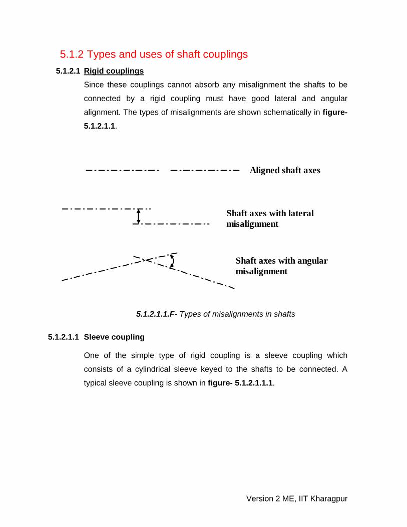
Since these couplings cannot absorb any misalignment the shafts to be
connected by a rigid coupling must have good lateral and angular
alignment. The types of misalignments are shown schematically in figure-5.1.2.1.1.
Aligned shaft axes
Shaft axes with lateralmisalignment
Shaft axes with angularmisalignment
5.1.2.1.1.F- Types of misalignments in shafts
5.1.2.1.1 Sleeve coupling
One of the simple type of rigid coupling is a sleeve coupling which
consists of a cylindrical sleeve keyed to the shafts to be connected. A
typical sleeve coupling is shown in figure- 5.1.2.1.1.1.
Version 2 ME, IIT Kharagpur

L
d 0 d
Key
Sleeve
Keyway
Shaft
b
5.1.2.1.1.1F- A typical sleeve coupling
Normally sunk keys are used and in order to transmit the torque safely it is
important to design the sleeve and the key properly. The key design is
usually based on shear and bearing stresses. If the torque transmitted is
T, the shaft radius is r and a rectangular sunk key of dimension b and
length L is used then the induced shear stress τ ( figure- 5.1.2.1.1.2) in
the key is given by
LT b r2
⎛ ⎞τ = ⎜ ⎟⎝ ⎠
and for safety
( )2T bLr < τy
where τy is the yield stress in shear of the key material. A suitable factor of
safety must be used. The induced crushing stress in the key is given as
brb LT r2 2
⎛ ⎞σ = ⎜ ⎟⎝ ⎠
and for a safe design
( )4T bLr < σc
where σc is the crushing strength of the key material.
Version 2 ME, IIT Kharagpur

Shear plane
Crushing plane
L
b
b
Key
5.1.2.1.1.2F- Shear and crushing planes in the key.
The sleeve transmits the torque from one shaft to the other. Therefore if di
is the inside diameter of the sleeve which is also close to the shaft
diameter d (say) and d0 is outside diameter of the sleeve, the shear stress
developed in the sleeve is ( )
0sleeve 4 4
0 i
16Tdd d
τ =π −
and the shear stress in the
shaft is given by shaft 3i
16Td
τ =π
. Substituting yield shear stresses of the
sleeve and shaft materials for τsleeve and τshaft both di and d0 may be
evaluated.
However from the empirical proportions we have:
d0 = 2di + 12.5 mm and L=3.5d.
These may be used as checks.
5.1.2.1.2 Sleeve coupling with taper pins
Torque transmission from one shaft to another may also be done using
pins as shown in figure-5.1.2.1.2.1.
Version 2 ME, IIT Kharagpur

L
d 0 d
Sleeve
a a
Shaft
Pin
5.1.2.1.2.1F- A representative sleeve coupling with taper pins.
The usual proportions in terms of shaft diameter d for these couplings are:
d0 = 1.5d, L = 3d and a = 0.75d.
The mean pin diameter dmean = 0.2 to 0.25 d. For small couplings dmean is
taken as 0.25d and for large couplings dmean is taken as 0.2d. Once the
dimensions are fixed we may check the pin for shear failure using the
relation
2mean
d2 d T4 2π⎛ ⎞ ⎛ ⎞τ =⎜ ⎟ ⎜ ⎟
⎝ ⎠ ⎝ ⎠.
Here T is the torque and the shear stress τ must not exceed the shear
yield stress of the pin material. A suitable factor of safety may be used for
the shear yield stress.
5.1.2.1.3 Clamp coupling A typical clamp coupling is shown in figure-5.1.2.1.3.1. It essentially
consists of two half cylinders which are placed over the ends of the shafts
to be coupled and are held together by through bolt.
Version 2 ME, IIT Kharagpur
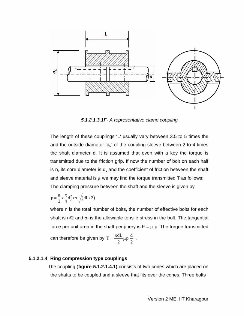
5.1.2.1.3.1F- A representative clamp coupling
The length of these couplings ‘L’ usually vary between 3.5 to 5 times the
and the outside diameter ‘d0’ of the coupling sleeve between 2 to 4 times
the shaft diameter d. It is assumed that even with a key the torque is
transmitted due to the friction grip. If now the number of bolt on each half
is n, its core diameter is dc and the coefficient of friction between the shaft
and sleeve material is μ we may find the torque transmitted T as follows:
The clamping pressure between the shaft and the sleeve is given by
( )2tc
np x d x dL / 22 4
π= σ
where n is the total number of bolts, the number of effective bolts for each
shaft is n/2 and σt is the allowable tensile stress in the bolt. The tangential
force per unit area in the shaft periphery is F = μ p. The torque transmitted
can therefore be given by dL dT p2 2
.π= μ .
5.1.2.1.4 Ring compression type couplings The coupling (figure-5.1.2.1.4.1) consists of two cones which are placed on
the shafts to be coupled and a sleeve that fits over the cones. Three bolts
Version 2 ME, IIT Kharagpur

are used to draw the cones towards each other and thus wedge them
firmly between the shafts and the outer sleeve. The usual proportions for
these couplings in terms of shaft diameter d are approximately as follows:
d1 = 2d + 15.24 mm L1 = 3d
d2 = 2.45d + 27.94 mm L2 = 3.5d + 12.7 mm
d3 = 0.23d + 3.17 mm L3 = 1.5d
and the taper of the cone is approximately 1 in 4 on diameter.
d
L1
L2
L3
d3d 2d 1
5.1.2.1.4.1F- A representative ring compression type coupling.
5.1.2.1.4 Flange coupling It is a very widely used rigid coupling and consists of two flanges keyed to
the shafts and bolted. This is illustrated in figure-5.1.2.1.4.2.
Version 2 ME, IIT Kharagpur

d 3
t1
KeyHub
Protecting flange
d1
d2
t3
t2
L
d
5.1.2.1.4.2F- A typical flange coupling
Design details of such couplings will be discussed in the next lesson. The
main features of the design are essentially
(a) Design of bolts
(b) Design of hub
(c) Overall design and dimensions.
5.1.2.2 Flexible coupling As discussed earlier these couplings can accommodate some
misalignment and impact. A large variety of flexible couplings are available
commercially and principal features of only a few will be discussed here.
5.1.2.2.1 Oldham coupling These couplings can accommodate both lateral and angular misalignment
to some extent. An Oldham coupling consists of two flanges with slots on
the faces and the flanges are keyed or screwed to the shafts. A cylindrical
Version 2 ME, IIT Kharagpur

piece, called the disc, has a narrow rectangular raised portion running
across each face but at right angle to each other. The disc is placed
between the flanges such that the raised portions fit into the slots in the
flanges. The disc may be made of flexible materials and this absorbs
some misalignment. A schematic representation is shown in figure- 5.1.2.2.1.1.
5.1.2.2.1.1F- A schematic diagram of an Oldham coupling
O
5.1.2.2.2 Universal joints
These joints are capable of handling relatively large angular misalignment
and they are widely used in agricultural machinery, machine tools and
automobiles.A typical universal joint is shown in figure- 5.1.2.2.2.1.There are
many forms of these couplings, available commercially but they essentially
consist of two forks keyed or screwed to the shaft. There is a center piece
through which pass two pins with mutually perpendicular axes and they connect
the two fork ends such that a large angular misalignment can be accommodated.
The coupling, often known as, Hooke’s coupling has no torsional rigidity nor can
it accommodate any parallel offset.
Version 2 ME, IIT Kharagpur

5.1.2.2.2.1F- A typical universal joint (Ref. [2])
5.1.2.2.2 Pin type flexible coupling One of the most commonly used flexible coupling is a pin type flexible
flange coupling in which torque is transmitted from one flange to the other
through a flexible bush put around the bolt. This is shown in the next
lesson and is shown in figure-5.2.2.1. These are used when excessive misalignment is not expected such as a
coupling between a motor and a generator or a pump mounted on a
common base plate. Detail design procedure for these couplings will be
discussed in the next lesson.
5.1.3 Summary of this Lesson Basic function of shaft couplings, their types and uses have been
discussed in this lesson. Among the rigid couplings some details of sleeve
couplings with key or taper pins, clamp couplings, ring compression type
couplings and flange couplings have been described. Among the flexible
couplings the Oldham coupling and universal joints are described and the
functions of pin type flexible couplings are given briefly.
Version 2 ME, IIT Kharagpur