wearing surfaces for timber decks surfaces for timber decks 11.1 introduction a wearing surface is a...
TRANSCRIPT

WEARING SURFACES FOR TIMBER DECKS
11.1 INTRODUCTION
A wearing surface is a layer placed on the bridge deck to form the roadway surface. It is the only portion of the bridge in direct contact with vehicle traffic. On timber bridges, a wearing surface is one of the most important components of the superstructure and serves two primary purposes. First, it provides a safe, smooth surface for vehicle traffic and improves the poor skid resistance of treated timber decks. Second, the wearing surface protects the deck from the abrasion and physical action of vehicle traffic. Without this protection, timber decks can wear rapidly, resulting in accelerated deterioration and reduced structural capacity.
Wearing surfaces vary in material and configuration and are classified as full or partial depending on the extent of deck coverage (Figure 11-1). A full wearing surface covers the entire bridge deck and is constructed of asphalt pavement, asphalt chip seal, lumber planks, or aggregate. A partial surface covers two longitudinal strips for vehicle tracking and is constructed from lumber planks or steel plates. Full surfaces are used on most bridges while partial surfaces are limited to single-lane, low-volume bridges only. This chapter discusses the performance considerations and design requirements for several full and partial wearing surfaces commonly used on timber decks.
11.2 DESIGN CONSIDERATIONS
Selection and design of a wearing surface depend on the weight, volume, and speed of traffic, as well as construction and maintenance costs. The objective is to provide the safest, most economical surface that meets use and performance requirements for the structure. Asphalt pavement or chip seals are normally the only acceptable surfaces for highway bridges and other bridges on paved roads. When bridges are located on local or low-volume roads, however, a wearing surface constructed of other materials may meet design objectives at a lower cost.
A wearing surface must interact with other bridge components for overall structure performance. In many cases, design considerations for the wearing surface are interrelated with those of the deck and other members of the structure and must be considered concurrently. Some of the general design and performance considerations for wearing surfaces are discussed below.
11-1

STRUCTURAL INTEGRITY
USER SAFETY
Figure 11-1. - General wearing surface configurations.
The wearing surface is a sacrificial component; that is, it is intended to wear away over a period of time. Thus, its performance and integrity cannot be ensured for the life of the structure. The wearing surface is not considered as a structural element for the purposes of load capacity or distribution; however, it must be designed to transmit vehicle loads to the bridge deck. In addition to vehicle live load, the surface may be subjected to longitudinal and transverse loads from vehicle braking, wind, and centrifugal force (Chapter 6). The strength of the wearing surface and the connection or bond between it and the deck must be sufficient to transmit these loads.
The wearing surface is the only portion of the structure that directly contacts passing vehicles. As a result, it is one of the most important components for user safety. Although many factors influence safety, perhaps the single most important factor is skid resistance. Asphalt pavement or chip seals provide the best skid resistance. The relative skid resistance of other materials, such as timber and steel, depends on the age and condition of the surface but is considerably less than that of asphalt. Skid resistance is related to deck drainage, regardless of the wearing surface material. When water collects on the deck surface, vehicles may hydroplane and become uncontrollable. Wearing surfaces must be free-draining and provide a level of skid resistance commensurate with the type
11-2

DECK PROTECTION
ECONOMICS
and speed of traffic. Lumber and steel wearing surfaces are not recommended when design speeds exceed approximately 30 miles per hour (mph) because of the poor skid resistance of these surfaces, particularly when wet.
In addition to skid resistance, the configuration of the wearing surface influences safety. Partial surfaces cover only a portion of the deck width, delineating the intended roadway for vehicle tracking. The lane width presented to the driver is restricted to two relatively narrow strips, and safe clearance is implied for any vehicle position on the strips. On single-lane bridges, one vehicle uses the structure at a time, and a partial surface may be acceptable. On multiple-lane bridges, however, lateral clearance is restricted when partial surfaces are used, and the potential for collision is greater. In addition, some partial wearing surfaces are elevated above the bridge deck. If a light vehicle rides off the surface, the change in elevation can cause a loss of vehicle control. As a result of these considerations, partial wearing surfaces should be restricted to single-lane bridges. When partial wearing surfaces are used on bridges intended for passenger vehicles, the thickness of the surface should not be more than 2 inches to reduce the probability of a vehicle riding off the surface and losing control.
One of the primary functions of a wearing surface is to protect the bridge deck. The surface material and thickness should be based on the expected weight and density of traffic. A thicker or more abrasion-resistant surface is required for heavy truck traffic or tire chain use. Partial wearing surfaces offer the least protection and frequently result in deck wear from vehicle off-tracking (Figure 11-2). In addition to protection from vehicle damage, the wearing surface should protect the deck from moisture and weathering effects. The best wearing surface is watertight and shields the deck and supporting members from direct exposure to the elements. Full-width asphalt or chip-seal surfaces drain water and protect the deck from moisture. Lumber, steel, and aggregate surfaces tend to trap moisture and increase susceptibility to decay.
The relative economy of wearing surfaces should be evaluated in terms of initial construction cost, the design life of the surface, and estimated costs for maintenance and replacement over the life of the structure. Wearing surface design life depends on the material and configuration of the surface as well as the weight and density of traffic. Surface life is difficult to estimate for the general case and should be based on site-specific information for projected traffic. Relative approximations of service life are given in the following sections of this chapter.
11-3

RIDEABILITY
Figure 11-2. - Severe abrasion on a nail-laminated lumber deck caused by vehicles off-tracking the partial steel plate wearing surface (photo courtesy of Sakee Poulakidas, USDA Forest Service).
When evaluating wearing surfaces, simple construction cost comparisons do not give an accurate indication of total economy and can be misleading. Although the initial cost for some surfaces may be higher than others, savings in future maintenance and replacement expenses over the life of the structure can more than offset the additional cost. Maintenance for plank surfaces generally involves complete replacement, while minor crack repair for asphalt surfaces may significantly extend service life without replacement. In general, maintenance costs are higher for partial surfaces that are elevated above the deck because they trap water and debris and require cleaning at regular intervals. Maintenance costs are also high for surfaces that are bolted to the deck and require access to the deck underside for tightening or replacement.
The type of wearing surface may have an effect on the service life of the deck. When field drilling for fasteners such as spikes, lag screws, or bolts is required for deck attachment, the preservative envelope of the deck is broken. This may lead to accelerated deck decay or deterioration, especially when the replacement interval of the wearing surface is frequent. Although effects on deck life are difficult to predict, the potential should be considered.
The rideability or user comfort provided by the wearing surface should be considered in design. In most applications, rideability is evaluated for light passenger vehicles and is related to the traffic speed. The roadway should be as smooth as possible without abrupt changes in texture or elevation.
11-4

The riding quality of the wearing surface should equal or surpass that of the adjacent approach roadways.
DEAD LOAD The dead load of wearing surfaces can vary significantly for the same surface thickness. For example, a 3-inch asphalt surface weighs approximately three times more than a lumber surface of the same thickness. Although this weight difference generally has little influence on the design of new structures, it may be an important consideration in the rehabilitation of existing bridges.
11.3 ASPHALT PAVEMENT
An asphalt pavement wearing surface consists of a layer of bituminous concrete that is spread and compacted on the bridge deck to produce a smooth, well-consolidated surface (Figure 11-3). It is perhaps the most desirable of all wearing surfaces because it effectively protects the entire deck from traffic abrasion and moisture and provides a smooth, skid-resistant surface. It is the only surface compatible with high-speed paved highways. The service life of an asphalt wearing surface depends not only on the weight and volume of traffic but also on the type of deck, local environmental conditions, and the preparation, design, and application of the asphalt pavement. When properly applied and maintained, asphalt wearing surfaces can provide good service for periods of 15 years or more.
Figure 11-3. - Asphalt pavement wearing surface on a timber bridge deck.
11-5
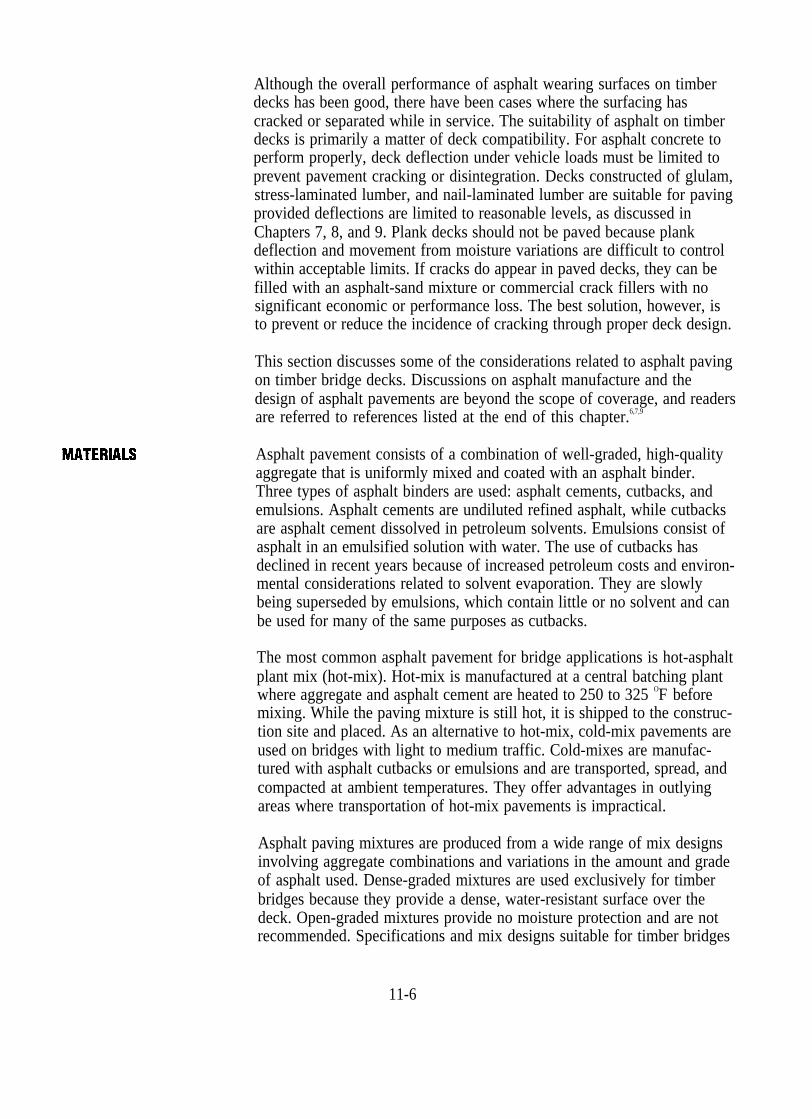
Although the overall performance of asphalt wearing surfaces on timber decks has been good, there have been cases where the surfacing has cracked or separated while in service. The suitability of asphalt on timber decks is primarily a matter of deck compatibility. For asphalt concrete to perform properly, deck deflection under vehicle loads must be limited to prevent pavement cracking or disintegration. Decks constructed of glulam, stress-laminated lumber, and nail-laminated lumber are suitable for paving provided deflections are limited to reasonable levels, as discussed in Chapters 7, 8, and 9. Plank decks should not be paved because plank deflection and movement from moisture variations are difficult to control within acceptable limits. If cracks do appear in paved decks, they can be filled with an asphalt-sand mixture or commercial crack fillers with no significant economic or performance loss. The best solution, however, is to prevent or reduce the incidence of cracking through proper deck design.
This section discusses some of the considerations related to asphalt paving on timber bridge decks. Discussions on asphalt manufacture and the design of asphalt pavements are beyond the scope of coverage, and readers are referred to references listed at the end of this chapter.6,7,9
Asphalt pavement consists of a combination of well-graded, high-quality aggregate that is uniformly mixed and coated with an asphalt binder. Three types of asphalt binders are used: asphalt cements, cutbacks, and emulsions. Asphalt cements are undiluted refined asphalt, while cutbacks are asphalt cement dissolved in petroleum solvents. Emulsions consist of asphalt in an emulsified solution with water. The use of cutbacks has declined in recent years because of increased petroleum costs and environmental considerations related to solvent evaporation. They are slowly being superseded by emulsions, which contain little or no solvent and can be used for many of the same purposes as cutbacks.
The most common asphalt pavement for bridge applications is hot-asphalt plant mix (hot-mix). Hot-mix is manufactured at a central batching plant where aggregate and asphalt cement are heated to 250 to 325 OF before mixing. While the paving mixture is still hot, it is shipped to the construction site and placed. As an alternative to hot-mix, cold-mix pavements are used on bridges with light to medium traffic. Cold-mixes are manufactured with asphalt cutbacks or emulsions and are transported, spread, and compacted at ambient temperatures. They offer advantages in outlying areas where transportation of hot-mix pavements is impractical.
Asphalt paving mixtures are produced from a wide range of mix designs involving aggregate combinations and variations in the amount and grade of asphalt used. Dense-graded mixtures are used exclusively for timber bridges because they provide a dense, water-resistant surface over the deck. Open-graded mixtures provide no moisture protection and are not recommended. Specifications and mix designs suitable for timber bridges
11-6

SURFACE PREPARATION
are normally maintained by state and federal agencies with responsibilities for road paving and maintenance. In most states, it is practical to use one of the standard mixes normally available from asphalt mix suppliers in the state.
Surface preparation of the bridge deck is perhaps the most important step in asphalt paving. As discussed in Chapter 4, bridge components are treated with oil-type preservatives because of the added moisture protection oil-type preservatives afford. Some of the same qualities that provide this added protection affect the physical properties and bonding capabilities of asphalt pavements. When the deck surface contains excess preservatives, the asphalt cannot bond properly to the deck and will eventually soften and disintegrate, or separate from the deck surface. Problems of this type can be eliminated when the deck is properly prepared.
Planning for asphalt pavement starts during the design process when the specifications are prepared. In an effort to provide as clean a surface as possible, treating specifications should require treatment by an empty-cell process, followed by an expansion bath or steaming. Depending on the treater, material treated in this manner will generally be free of excessive surface deposits of preservative or solvent. The level of free preservatives may be further reduced by specifying one of the new clean creosote treatments mentioned in Chapter 4. It may be beneficial to discuss treatment alternatives with a local treater or national treating organization to determine the best treatment based on local availability.
After treating, most material will continue to exude preservative or solvent volatiles, and time must be allowed for excess material within the wood to evaporate. Unless the preservatives stabilize, a satisfactory bond will not be achieved between the deck surface and the asphalt. The rate at which these volatiles leave the wood depends on the type of preservative and temperature. Preservatives in heavy-oil solvents leave the surface at a slower rate than light-oil solvents, but the rate for both increases as temperatures rise. When practical, treated timber decks should not be paved for 30 to 45 days after the material has been treated. In the interim, deck material can be stored where air can circulate freely around all surfaces, or be installed with a blotter material (discussed in the following paragraphs) and paved at a future date.
When decks must be placed with free surface preservatives, or before all residuals have evaporated, application of a surface blotter before paving can greatly improve asphalt bonding. A blotter mixture of dust and 10 to 20 percent crushed material passing the No. 8 sieve, spread at a rate of 10 to 15 lb/yd2, is recommended. The blotter is spread on the deck and immediately rolled with a rubber-tired roller. After the excess preservative has been absorbed (approximately 1 week), the blotter is removed by
11-7
PLACEMENT ANDCONFIGURATION
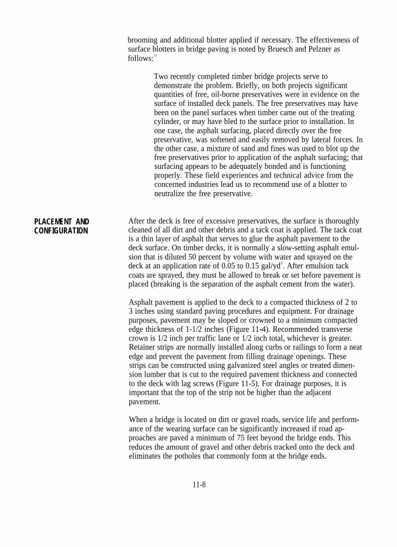
brooming and additional blotter applied if necessary. The effectiveness of surface blotters in bridge paving is noted by Bruesch and Pelzner as follows:11
Two recently completed timber bridge projects serve to demonstrate the problem. Briefly, on both projects significant quantities of free, oil-borne preservatives were in evidence on the surface of installed deck panels. The free preservatives may have been on the panel surfaces when timber came out of the treating cylinder, or may have bled to the surface prior to installation. In one case, the asphalt surfacing, placed directly over the free preservative, was softened and easily removed by lateral forces. In the other case, a mixture of sand and fines was used to blot up the free preservatives prior to application of the asphalt surfacing; that surfacing appears to be adequately bonded and is functioning properly. These field experiences and technical advice from the concerned industries lead us to recommend use of a blotter to neutralize the free preservative.
After the deck is free of excessive preservatives, the surface is thoroughly cleaned of all dirt and other debris and a tack coat is applied. The tack coat is a thin layer of asphalt that serves to glue the asphalt pavement to the deck surface. On timber decks, it is normally a slow-setting asphalt emulsion that is diluted 50 percent by volume with water and sprayed on the deck at an application rate of 0.05 to 0.15 gal/yd2. After emulsion tack coats are sprayed, they must be allowed to break or set before pavement is placed (breaking is the separation of the asphalt cement from the water).
Asphalt pavement is applied to the deck to a compacted thickness of 2 to 3 inches using standard paving procedures and equipment. For drainage purposes, pavement may be sloped or crowned to a minimum compacted edge thickness of 1-1/2 inches (Figure 11-4). Recommended transverse crown is 1/2 inch per traffic lane or 1/2 inch total, whichever is greater. Retainer strips are normally installed along curbs or railings to form a neat edge and prevent the pavement from filling drainage openings. These strips can be constructed using galvanized steel angles or treated dimension lumber that is cut to the required pavement thickness and connected to the deck with lag screws (Figure 11-5). For drainage purposes, it is important that the top of the strip not be higher than the adjacent pavement.
When a bridge is located on dirt or gravel roads, service life and performance of the wearing surface can be significantly increased if road approaches are paved a minimum of 75 feet beyond the bridge ends. This reduces the amount of gravel and other debris tracked onto the deck and eliminates the potholes that commonly form at the bridge ends.
11-8

GEOTEXTILE FABRICS
Figure 11-4. - Typical asphalt pavement wearing surface cross section.
Steel angle retainer
Treated timber retainer
Figure 11-5. - Types of retainer strips for asphalt pavement wearing surfaces.
Geotextile fabrics are synthetic engineering fabrics that were originally developed to provide additional stability and load distribution in numerous geotechnical (soils) and hydraulic applications. Specialized paving fabrics have been used for several years to improve pavement performance and longevity. When properly placed between the bridge deck and asphalt pavement, geotextile fabrics can improve the bond between the asphalt and the deck surface, provide increased moisture resistance of the surface, and reduce or eliminate pavement cracking at glulam panel joints.
Geotextile fabrics for bridge paving are available in two types: plain and asphalt impregnated. Plain fabrics consist of a nonwoven geotextile fabric only and are commonly available in rolls 12 feet wide. Impregnated
11-9

fabrics have a layer of rubberized asphalt bonded to one side and are normally available in 12- and 36-inch widths. The impregnated fabrics are most commonly used on timber decks where heat from the asphalt causes the rubberized asphalt layer to bond to the deck. This provides improved adhesion and an impermeable barrier to moisture.
Paving with geotextile fabrics involves the same deck surface preparation previously discussed. After the deck is free of excess preservative and debris, the fabrics can be placed. A tack coat is necessary before placing plain fabrics but is not required for impregnated fabrics. The fabric is rolled on the deck with an overlap between adjacent strips of 2 to 3 inches. On transverse glulam decks, the narrow-width impregnated fabrics also can be placed transverse over panel joints only (Figure 11-6). After the fabric is rolled in place, a tack coat between the fabric and asphalt concrete layer is required for both plain and impregnated fabrics. This generally consists of an asphalt emulsion spread to achieve a residual asphalt layer of 0.10 to 0.15 gal/yd2 (this may vary among fabric brands and should be verified with the manufacturer). Pavement is then applied to the surface in the usual manner. A sequence of photos showing a deck-paving project using impregnated fabric is given in Figure 11-7.
Figure 11-6. - Placement of impregnated geotextile fabric on transverse glulam deck panels.
11-10

Figure 11-7. - Asphalt paving sequence on a glulam bridge deck using impregnated geotextile fabric. (A) Geotextile fabric is roiled longitudinally over the cleaned deck (note that the backing paper on the asphalt side of the fabric is removed as the fabric is rolled). (B) Completed fabric placement.
11-11
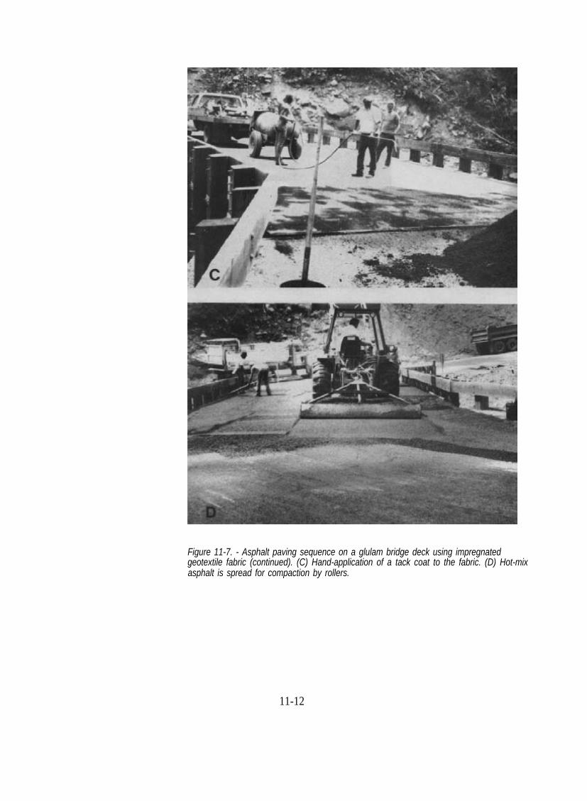
Figure 11-7. - Asphalt paving sequence on a glulam bridge deck using impregnated geotextile fabric (continued). (C) Hand-application of a tack coat to the fabric. (D) Hot-mix asphalt is spread for compaction by rollers.
11-12

Figure 11-7. - Asphalt paving sequence on a glulam bridge deck using impregnatedgeotextile fabric (continued). (E) A corner of the fabric is pulled back after application ofthe hot asphalt, showing the bond between the rubberized asphalt on the fabric and thebridge deck. (F) The completed wearing surface (photos courtesy of Ron Vierra, USDAForest Service).
11-13

11.4 ASPHALT CHlP SEAL
MATERIALS
An asphalt chip seal consists of a sprayed application of liquid asphalt covered with a layer of selected aggregate (Figure 11-8). It is not considered a pavement but an asphalt surface treatment that seals the deck surface and protects it from the abrasive effects of traffic. Chip seals have been used with great success on timber bridge decks and have provided service lives of 15 years or more, depending on traffic conditions. They are well suited for most timber bridge applications and provide a smooth, even surface that is compatible with paved roadways. The thinner chip seal surface normally provides added flexibility that is less susceptible to cracking than the more rigid asphalt-concrete pavements.
Figure 11-8. - Asphalt chip seal wearing surface on a timber bridge deck.
Materials for chip seals consist of the asphalt binder and the aggregate. Rapid-setting emulsified asphalts and soft grades of cutbacks are usually best suited for chip seals. Application rates vary with the type of binder and aggregate but are normally in the range of 0.20 to 0.35 gal/yd2 for emulsions and 0.15 to 0.25 gal/yd2 for cutbacks. Aggregates are normally 3/8- or 1/2-inch angular material that is as uniformly graded as economically practical. Most hard aggregates such as gravel, crushed stone, or slag can be successfully used if they are clean. If aggregates are dirty or covered with dust, the coating forms a film that prevents asphalt-aggregate adhesion. Aggregate spread rates depend on the size and quality of aggregate and range from approximately 20 to 25 lb/yd2 for 3/8-inch material to 25 to 30 lb/yd2 for 1/2-inch material. As with asphalt pavement, the
11-14

PLACEMENT ANDCONFIGURATION
designer should check with local state or county road agencies to determine the best asphalt-aggregate combination and application rates for the local area. Additional information is given in references listed at the end of this chapter.5,7
Chip seals can be applied as a single treatment or as a multiple treatment. Single treatments consist of one layer of asphalt and one layer of aggregate. Multiple treatments are built by adding additional layers of asphalt and progressively smaller-size aggregate. For bridge applications, a double treatment approximately 3/4 inch thick provides much better performance than a single treatment. Thicker surfaces can be built by increasing aggregate size.
Surface preparation for asphalt chip seals is the same as previously discussed for asphalt pavement. Unless the surface is clean and free of excess preservatives, the asphalt will not adhere to the deck. After the deck is cleaned, the asphalt binder is applied to the bridge by an asphalt distributor. The distributor is a tank truck equipped with a heater, pump, and spray-bar assembly that uniformly sprays the asphalt over the deck surface (Figure 11-9). The spray bar is extended from the rear of the truck to cover a width in one pass of 6 to 30 feet, depending on the capacity of the pump. During the spraying process, it is important that the pump and spray bar nozzles be properly calibrated and adjusted to deliver a uniform, even layer of asphalt at the required rate.
Figure 11-9. - Asphalt binder for a chip seal being applied to a timber bridge deck by an asphalt distributor truck (photo courtesy of Paul Cole, USDA Forest Service).

Aggregate is applied over the asphalt using a spreader. Spreaders range from simple vane spreaders or mechanical spreaders to highly efficient self-propelled machines. Vane spreaders attach to the dump truck tailgate and fan out slightly more than the truck width. The application rate is controlled by the feed gate opening and the speed of the truck as it backs up. Mechanical spreaders are hoppers on wheels that connect to the truck tailgate. Although the application rate also depends on truck speed, mechanical spreaders provide a more controlled, even aggregate spread across the lane than vane spreaders. The most suitable spreaders are self-propelled models (Figure 11-10). The aggregate truck hitches to the rear of the spreader, dumps aggregate into a receiving hopper, and is pulled by the spreader. Aggregate from the hopper is moved by conveyer to the front of the spreader where it is evenly distributed by a spread roller. For all types of spreaders, a check of the aggregate application rate can be made by laying 1 yd2 of cloth or building paper on the ground and weighing the amount of aggregate distributed after the spreader passes.
Figure 11-10. - Crushed aggregate chips are applied over an asphalt binder by a self-propelled aggregate spreader (photo courtesy of Paul Cole, USDA Forest Service).
Immediately following chip application, it is important that the surface be compacted to properly seat the aggregate in the asphalt binder. A towed or self-propelled rubber-tire roller is recommended for use on chip seals because the tires force the aggregate firmly into the asphalt without crushing (Figure 11-11). Steel-wheel rollers bridge over smaller particles or depressions in the surface and may crush the aggregate. After the layer is compacted, the asphalt is allowed to set so that the aggregate is tightly
11-16

GEOTEXTILE FABRICS
11.5 LUMBER SURFACE
bonded. The layer may then be brushed or broomed with motorized equipment to remove excessive chips, and the second treatment is applied using the same procedures.
Figure 11-1. - Rubber-tire roller of the type used for compacting asphalt chip seal wearing surfaces.
Geotextile fabrics previously discussed for asphalt pavement can be used with asphalt chip seals. Plain fabrics are recommended at this time because the use of impregnated fabrics with chip seals is still in the developmental stage, and results are not yet conclusive. When fabrics are used, the rate of asphalt application must be increased to saturate the fabric layer. This increase is generally 0.10 to 0.15 gal/yd2 residual asphalt, but should be verified with the fabric manufacturer.
Lumber wearing surfaces consist of a series of lumber planks placed edge to edge across the deck width (Figure 11-12). They are frequently used on single- and multiple-lane bridges and are compatible with all types of timber decks. Lumber surfaces are probably the most economical full surface to construct and maintain on bridges located on low-speed, unpaved roads. Service life is typically 5 to 12 years depending on the weight and volume of traffic and plank thickness. When gravel or other abrasive material is tracked on the surface, service life is significantly decreased.
11-17

MATERIALS
Figure 11-12. - Typical lumber wearing surface.
Lumber surfaces are constructed of planks that are 10 to 12 inches wide and a minimum of 8 feet long. Random-length, rough-sawn planks are commonly used and are field cut to required length. It is desirable to leave the wide faces of the planks unplaned to provide additional surface texture. Plank edges are rough sawn, or are edge planed (S2E) to provide consistent plank widths. Plank thickness depends on traffic weight and density. Guidelines for thickness based on vehicle weight are given below; however, the wearing surface should not be thicker than the bridge deck.
Selection of wood species for planks should be based on the considerations of wearability and dimensional stability. Both of these properties are directly related to species density (Chapter 3). As density increases, planks wear better but are more susceptible to dimensional changes and deformation because of moisture content changes. Species such as Douglas Fir-Larch, Hemlock, and Spruce provide good wearability with acceptable dimensional stability. Regardless of species, wearability and dimensional stability are increased when edge-grain planks are used (Figure 11-13). Flat-grain planks wear faster and may cup or twist because of moisture
11-18

CONFIGURATION
DECK ATTACHMENT
Figure 11-13. - Edge-grain and flat-grain plank orientations for lumber wearing surfaces.
changes. When edge-grain material is not available, flat-grain planks should be used with the bark side up (heart side down).
Under low traffic volumes or light vehicle loads, planks may decay before they wear out, especially in the areas not contacted by traffic. Under these conditions it may be economically beneficial to treat planks with preservatives to extend their service life. When planks are treated, waterborne preservatives should be used (Chapter 4). Oil-type preservatives reduce skid resistance and may create a vehicle safety hazard.
Wearing surface planks are typically oriented in the direction of traffic. A transverse or diagonal orientation may be used but planks wear faster when traffic is across the grain. The most economical arrangement is an alternating repetition of longitudinal planks with odd lengths at the bridge ends (Figure 11-14). End joints in adjacent planks are staggered by a minimum of 3 feet. When seasoned planks are used, a gap of approximately 1/4 inch is left between edge joints to allow for expansion. Tight edge joints are used for unseasoned (green) planks.
The configuration of a lumber surface at bridge ends should minimize the effects of vehicle impact on planks, especially on dirt or gravel roads where potholes develop at bridge approaches. Beveling of plank ends on bridge approaches reduces vehicle impact forces and improves wearing surface performance and longevity (Figure 11-15).
Performance of a lumber wearing surface depends on the plank attachment to the bridge deck. The connection must keep the planks firmly attached, minimize deck damage, and permit easy removal for plank replacement. The two fasteners most commonly used are spikes and lag screws. Bolts are not economical and require access to the deck underside for installation and removal. Whenever possible, deck fasteners and hardware should be recessed below the roadway surface. This reduces tire damage and protects fasteners from road maintenance vehicles such as snow plows and
11-19
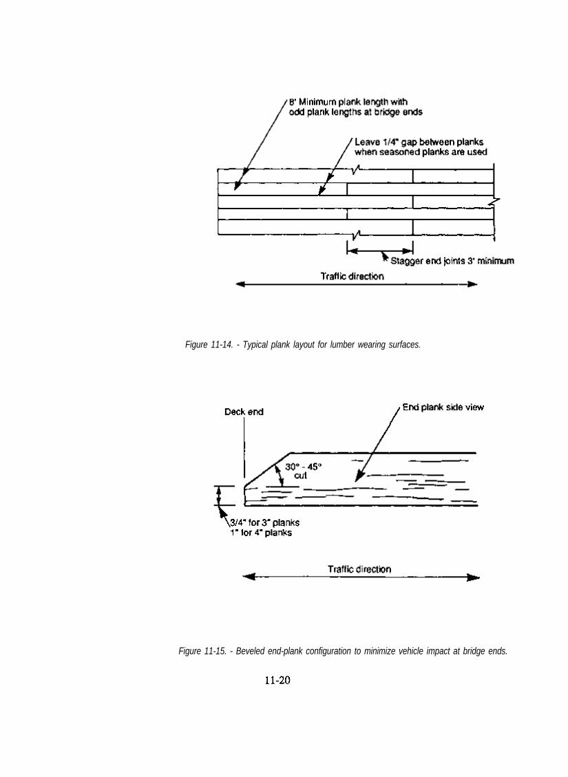
Figure 11-14. - Typical plank layout for lumber wearing surfaces.
Figure 11-15. - Beveled end-plank configuration to minimize vehicle impact at bridge ends.

motor graders. The recessed hole does provide a trap for dirt, water, and other material, but this has little or no effect on the deck or wearing surface. These depressions can be sealed with mastic compound or caulked if considered necessary by the designer.
Field placement of fasteners such as spikes or lag screws requires penetration of the preservative envelope of the deck, providing access for organisms that decay untreated timber. Decay susceptibility in decks is especially significant because the deck has a high exposure to moisture and debris accumulation. To minimize decay and prevent splitting, all fasteners should be placed in lead holes that are prebored and field treated with liquid wood preservative. When fasteners are permanently removed, as when planks are replaced, holes are re-treated with preservatives and tightly plugged with treated wood dowels (Figure 11-16). Protection of timber members from decay is critical to the longevity of the deck and cannot be overemphasized. Failure to properly install and replace fasteners can result in accelerated decay, which reduces deck service life.
Figure 11-16. - Treated dowel plug for wearing surface fastener holes.
Spikes Spikes are the most common fastener for lumber wearing surfaces because they are inexpensive and simple to install. One disadvantage of using spikes is their tendency to loosen from moisture loss in the planks or from structure vibrations. Safety hazards can result when planks move or spikes project above the wearing surface. These problems can be minimized by proper spike placement and maintenance.
Spikes for wearing surfaces should be annularly (ring shanked) or helically (spiral) threaded (Figure 11-17). Common steel spikes with a smooth finish are not recommended because they loosen under repeated loading. A minimum spike diameter of 1/4 inch is recommended for planks 3 inches thick or less. When planks are more than 3 inches thick, 5/16- or
11-21
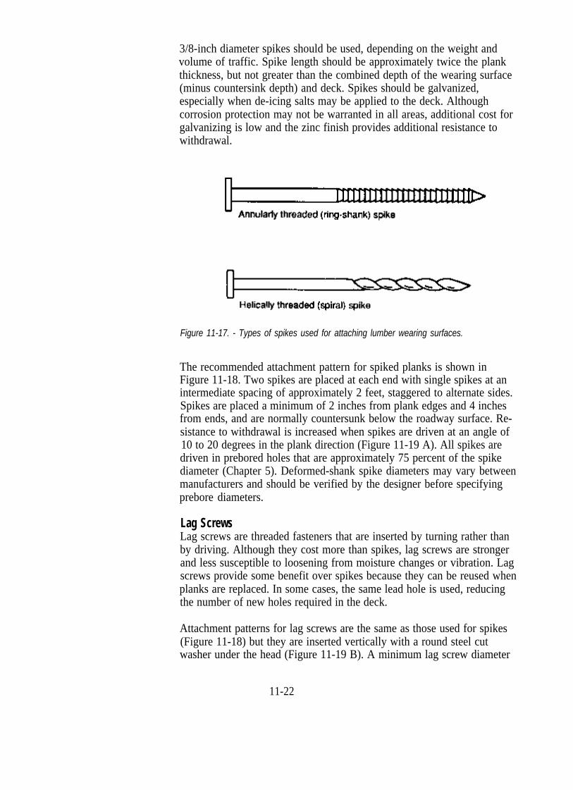
3/8-inch diameter spikes should be used, depending on the weight and volume of traffic. Spike length should be approximately twice the plank thickness, but not greater than the combined depth of the wearing surface (minus countersink depth) and deck. Spikes should be galvanized, especially when de-icing salts may be applied to the deck. Although corrosion protection may not be warranted in all areas, additional cost for galvanizing is low and the zinc finish provides additional resistance to withdrawal.
Figure 11-17. - Types of spikes used for attaching lumber wearing surfaces.
The recommended attachment pattern for spiked planks is shown in Figure 11-18. Two spikes are placed at each end with single spikes at an intermediate spacing of approximately 2 feet, staggered to alternate sides. Spikes are placed a minimum of 2 inches from plank edges and 4 inches from ends, and are normally countersunk below the roadway surface. Resistance to withdrawal is increased when spikes are driven at an angle of 10 to 20 degrees in the plank direction (Figure 11-19 A). All spikes are driven in prebored holes that are approximately 75 percent of the spike diameter (Chapter 5). Deformed-shank spike diameters may vary between manufacturers and should be verified by the designer before specifying prebore diameters.
Lag Screws Lag screws are threaded fasteners that are inserted by turning rather than by driving. Although they cost more than spikes, lag screws are stronger and less susceptible to loosening from moisture changes or vibration. Lag screws provide some benefit over spikes because they can be reused when planks are replaced. In some cases, the same lead hole is used, reducing the number of new holes required in the deck.
Attachment patterns for lag screws are the same as those used for spikes (Figure 11-18) but they are inserted vertically with a round steel cut washer under the head (Figure 11-19 B). A minimum lag screw diameter
11-22
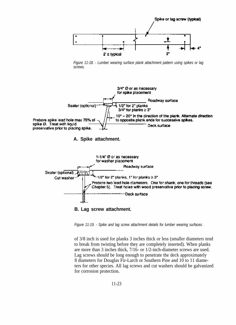
Figure 11-18. - Lumber wearing surface plank attachment pattern using spikes or lag screws.
A. Spike attachment.
B. Lag screw attachment.
Figure 11-19. - Spike and lag screw attachment details for lumber wearing surfaces.
of 3/8 inch is used for planks 3 inches thick or less (smaller diameters tend to break from twisting before they are completely inserted). When planks are more than 3 inches thick, 7/16- or 1/2-inch-diameter screws are used. Lag screws should be long enough to penetrate the deck approximately 8 diameters for Douglas Fir-Larch or Southern Pine and 10 to 11 diameters for other species. All lag screws and cut washers should be galvanized for corrosion protection.
11-23
Lead holes for lag screws are prebored with two diameters: one diameter for the upper shank portion, and a smaller diameter for the threaded length. The lead hole for the shank portion is 1/16 inch greater in diameter than the lag screw shank. The lead hole for the threaded length varies from 40 to 75 percent of the screw shank diameter depending on deck species. For Douglas Fir-Larch and Southern Pine, a hole diameter of 60 to 75 percent of the shank diameter is used. Prebore diameters for other species are given in Chapter 5.
11.6 STEEL RUNNING PLATES
MATERIALS
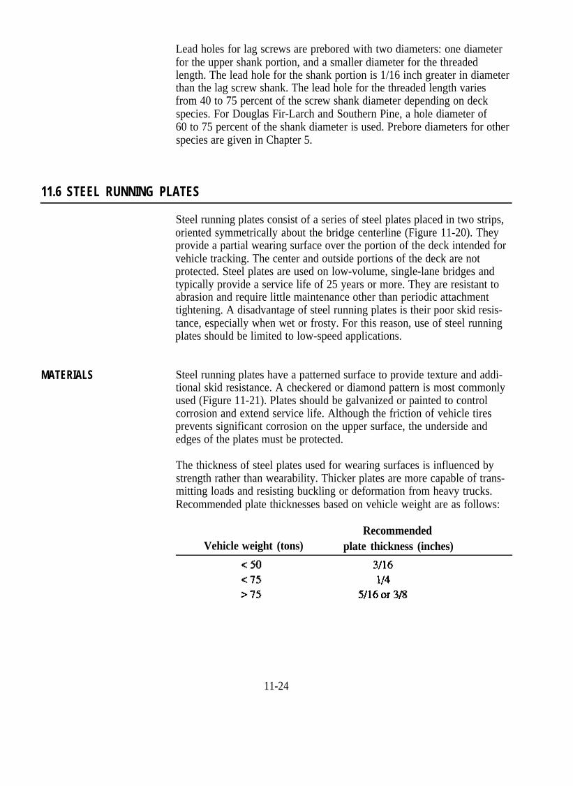
Steel running plates consist of a series of steel plates placed in two strips, oriented symmetrically about the bridge centerline (Figure 11-20). They provide a partial wearing surface over the portion of the deck intended for vehicle tracking. The center and outside portions of the deck are not protected. Steel plates are used on low-volume, single-lane bridges and typically provide a service life of 25 years or more. They are resistant to abrasion and require little maintenance other than periodic attachment tightening. A disadvantage of steel running plates is their poor skid resistance, especially when wet or frosty. For this reason, use of steel running plates should be limited to low-speed applications.
Steel running plates have a patterned surface to provide texture and additional skid resistance. A checkered or diamond pattern is most commonly used (Figure 11-21). Plates should be galvanized or painted to control corrosion and extend service life. Although the friction of vehicle tires prevents significant corrosion on the upper surface, the underside and edges of the plates must be protected.
The thickness of steel plates used for wearing surfaces is influenced by strength rather than wearability. Thicker plates are more capable of transmitting loads and resisting buckling or deformation from heavy trucks. Recommended plate thicknesses based on vehicle weight are as follows:
Recommended Vehicle weight (tons) plate thickness (inches)
11-24

Figure 11-20. - Steel running plate wearing surface on a timber bridge deck.
Figure 11-21. - Typical checkered surface pattern on steel running plates.
11-25

CONFIGURATION The configuration of steel plates must be adequate to protect the deck over the expected range in vehicle track widths. These widths vary from less than 5 feet for compact cars to 7 feet or more for off-highway trucks. The inside spacing between plates is commonly 2 to 4 feet, with plate width from 2 to 4 feet, depending on vehicle track widths (Figure 11-22). When approach roadways are curved, additional plate width should be provided to protect the deck from vehicle off-tracking.
Figure 11-22. - Typical steel plate wearing surface cross section.
Individual plates should be no less than 8 feet long in the longitudinal direction. For short-span bridges, plates may be welded at butt joints to form a continuous surface. However, if welding is done on the deck, precautions must be taken to avoid deck damage during the welding process. On longer spans, continuous plate length should be limited to approximately 12 feet and a 1/4-inch gap left at butt joints to allow for thermal expansion of the steel.
DECK ATTACHMENT Steel plates are attached to the bridge deck with 1/2-inch-diameter bolts or lag screws (Figure 11-23). Bolts should be provided with malleable iron or steel cut washers and self-locking nuts on the deck underside. Lag screws should be the same length as those recommended for lumber surfaces. Fasteners for steel plates cannot be recessed below the roadway and fastener heads should be smooth to avoid tire damage. Bolts are preferable to lag screws because they provide a more positive connection, although they must be tightened from the deck underside. All fasteners should be galvanized and placed in prebored holes treated with a liquid wood preservative.
The attachment configuration for steelplates is the same for bolts and lag screws (Figure 11-24). Plate ends are attached with three fasteners: one at the plate center and one on each edge. Intermediate fasteners are placed along plate edges at 1-1/2- to 2-1/2-foot intervals. The distance from the center of the fastener to the plate end or edge should be 1-1/2 to 2 inches.
11-26

Fastener holes in the steel plates are commonly 1/16 to 1/8 inch larger than the fastener diameter, but may be slotted or oversized to allow for construction tolerances or plate expansion. Whenever possible, plate holes should be located on the flat unpatterned portion of the plate. When slotted or oversized holes are used, a steel cut washer should be placed under the fastener head (washers are not required when dome head bolts are used).
A. Bolted attachment
B. Lag screw attachment
Figure 11-23. - Bolt and lag screw attachment details for steel plate wearing surfaces.
11-27

Figure 11-24. - Steel plate wearing surface attachment pattern using bolts or lag screws.
11.7 LUMBER RUNNING PLANKS
MATERIALS
Lumber running planks are a series of sawn lumber planks placed edge to edge to form two longitudinal surfaces (Figure 11-25). They are similar to steel running plates in that they provide a wearing surface over the portion of the deck intended only for vehicle tracking. Lumber running planks are used on single-lane, low-speed, rural bridges and on special-purpose roads not intended for public traffic. Service life depends on the traffic weight and volume as well as the surface thickness. Under light loads, planks typically provide a service life of 4 to 8 years. When subjected to heavy truck traffic, planks may deteriorate in 2 years or less.
There are two notable disadvantages with lumber running planks. First, the difference in elevation between the wearing surface and the deck can be a safety hazard when vehicles track off the surface. This hazard is most serious for light passenger traffic or when thick planks are used. Second, the opening between the running planks serves as a trap for debris, requires increased maintenance, and can cause water to pond on watertight decks, creating a safety hazard to motorists and increasing the potential for deck decay.
Lumber running planks are constructed of planks that are 10 to 12 inches wide and a minimum of 8 feet long. Planed edges are not required, and planks should be left in a rough-sawn condition for enhanced vehicle traction. Considerations for plank species and grain orientation are similar to those previously discussed for lumber surfaces. Plank thickness is based on vehicle weight and traffic density. Running planks are more susceptible to mechanical damage than are comparable lumber surfaces because of vehicle off-tracking on the outside plank edges. Planks for bridges that carry heavy vehicles must be thicker. Recommended plank thicknesses based on vehicle weight are given below; however, running planks on bridges intended for public traffic should not be more than 2 inches thick because cars may lose control if they leave the plank surface.
11-28

CONFIGURATION
Figure 11-25. - Timber bridge deck with lumber running planks.
Running planks will normally wear out or deteriorate from mechanical damage before they decay. Treatment with preservatives is required only when low traffic volumes or light loads will result in reduced abrasion and mechanical damage. Under these conditions, biological attack may become important and planks may be treated with waterborne preservatives for extended life.
The transverse configuration of lumber running planks is based on anticipated vehicle track widths discussed for steel running plates (Section 11.6). In addition, surface spacing and width should be based on consideration of elevation differences between the deck and wearing surface. Additional width should be provided as necessary to reduce the potential for vehicle off-tracking, especially when passenger vehicles use the structure or when approach roadways are curved. For passenger vehicles, a maximum spacing of 2 feet between surfaces is recommended (Figure 11-26). Surface widths vary for different track widths, but are commonly four planks wide (approximately 4 feet when nominal 12-inch planks are used).
11-29

DECK ATTACHMENT
Figure 11-26. - Typical lumber running plank wearing surface cross section.
In the longitudinal direction, lumber running planks are similar to full lumber surfaces. The most economical configuration is an alternating repetition of plank lengths with odd lengths at the bridge ends (Figure 11-27). End joints in adjacent planks should be staggered a minimum of 3 feet, and plank ends on bridge approaches should be beveled to minimize vehicle impact.
Lumber running planks are attached to the deck with spikes or lag screws, as discussed for lumber surfaces. A bolted attachment configuration that employs threaded rods and steel angle brackets can also be used (Figure 11-28). Using this bolted configuration, deck attachment holes in glulam panel decks can be bored before preservative treatment of the panels. Thus, running planks can be installed and replaced without boring
Figure 11-27. - Typical plank layout for a lumber running plank wearing surface.
11-30

End view
Figure 11-28. - Attachment detail for lumber running planks using threaded rods and steel angle brackets.
additional deck holes. However, plank installation and replacement using this attachment configuration is more difficult, compared to conventional attachment with spikes or lag screws.
11.8 AGGREGATE SURFACE
MATERIALS
Aggregate wearing surfaces consist of a layer of crushed rock or other material placed across the bridge deck (Figure 11-29). These surfaces are inexpensive, easy to construct and maintain, and blend into the surrounding landscape. Aggregate surfaces are used primarily on native log stringer bridges or other temporary structures on low-volume, unpaved roads. They are not commonly used on lumber or glulam decks because they are heavy, hold moisture, and can cause severe abrasion to the bridge deck when the surface thickness is reduced by traffic.
Aggregate surfaces are constructed of any material that provides a good traffic surface and drains well. Materials that are frequently used include gravel, crushed rock, pit-run, shot rock, coarse sand, and coarse mineral soil. The material should provide a good running surface and resist decomposition from moisture and repeated vehicle loading.

CONFIGURATION
Figure 11-29. - Aggregate wearing surface on a timber bridge deck.
The depth of an aggregate surface must be sufficient to prevent abrasion and protect the deck during maintenance operations such as grading and snow removal. Minimum recommended depths are 4 inches for light vehicles and 6 inches for heavy truck traffic. In either case, depth should not be less than three times the diameter of the largest material in the surface. Where considerations for stream siltation are important, aggregate surfaces are placed on geotextile fabric (Figure 11-30).
11.9 SELECTED REFERENCES
1. American Association of State Highway and Transportation Officials. 1983. Standard specifications for highway bridges. 13th ed. Washington, DC: American Association of State Highway and Transportation Officials 394 p.
2. American Association of State Highway and Transportation Officials. 1986. AASHTO guide for design of pavement structures. Washington, DC: American Association of State Highway and Transportation Officials. [350 p.].
3. American Institute of Timber Construction. 1985. Timber construction manual. 3d ed. New York: John Wiley and Sons, Inc. 836 p.
4. Anderson, L.O.; Heebink, T.B.; Oviatt, A.E. 1971. Construction guide for exposed wood decks. Portland, OR: U.S. Department of Agriculture, Forest Service, Pacific Northwest Forest and Range Experiment Station. 78 p.
11-32
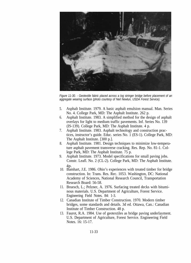
Figure 11-30. - Geotextile fabric placed across a log stringer bridge before placement of an aggregate wearing surface (photo courtesy of Neil Newlun, USDA Forest Service).
5. Asphalt Institute. 1979. A basic asphalt emulsion manual. Man. Series No. 4. College Park, MD: The Asphalt Institute. 262 p.
6. Asphalt Institute. 1983. A simplified method for the design of asphalt overlays for light to medium traffic pavements. Inf. Series No. 139 (IS-139). College Park, MD: The Asphalt Institute. 4 p.
7. Asphalt Institute. 1983. Asphalt technology and construction practices, instructor’s guide. Educ. series No. 1 (ES-1). College Park, MD: The Asphalt Institute. [300 p.].
8. Asphalt Institute. 1981. Design techniques to minimize low-tempera-ture asphalt pavement transverse cracking. Res. Rep. No. 81-1. College Park, MD: The Asphalt Institute. 75 p.
9. Asphalt Institute. 1973. Model specifications for small paving jobs. Constr. Leafl. No. 2 (CL-2). College Park, MD: The Asphalt Institute. 4p.
10. Bamhart, J.E. 1986. Ohio’s experiences with treated timber for bridge construction. In: Trans. Res. Rec. 1053. Washington, DC: National Academy of Sciences, National Research Council, Transportation Research Board: 56-58.
11. Bruesch, L.; Pelzner, A. 1976. Surfacing treated decks with bitumi-nous materials. U.S. Department of Agriculture, Forest Service. Engineering Field Notes. 84: 1-3.
12. Canadian Institute of Timber Construction. 1970. Modern timber bridges, some standards and details. 3d ed. Ottawa, Can.: Canadian Institute of Timber Construction. 48 p.
13. Faurot, R.A. 1984. Use of geotextiles as bridge paving underlayment. U.S. Department of Agriculture, Forest Service. Engineering FieldNotes. 16: 15-17.
11-33

14. Nagy, M.M.; Trebett, J.T.; Wellburn, G.V. 1980. Log bridge con-struction handbook. Vancouver, Can.: Forest Engineering Research Institute of Canada. 421 p.
15. National Forest Products Association. 1986. National design specifi-cation for wood construction. Washington, DC: National Forest Products Association. 87 p.
16. Sprinkel, M.M. 1978. Glulam timber deck bridges. VHTRC 79-R26. Charlottesville, VA: Virginia Highway and Transportation Research Council. 33 p.
17. US. Department of Transportation, Federal Highway Administration. 1979. Standard plans for highway bridges. Timber bridges. Washington, DC: U.S. Department of Transportation, Federal Highway Administration. Vol. 3. 19 p.
18. Weyerhaeuser Company. 1980. Weyerhaeuser glulam wood bridgesystems. Tacoma, WA: Weyerhaeuser Co. 114 p.