wearable computer system for remote health state … of the system is a wearable computer that ......
TRANSCRIPT

Politecnico di Milano Scuola di Ingegneria dell’Informazione
Corso di Laurea Magistrale in Ingegneria Informatica Academic Year 2013/14
!!!
Wearable computer system
for remote health state monitoring !!
Alexey Zykov (mat. 764416)
!!
Supervisor: Sara Comai
Co-supervisor: Fabio Salice
!!

Abstract
In this work the prototype of the computer system for health monitoring was developed. The heart of the system is a wearable computer that is intended for use by the people whose health should be monitored. The device is connected to several biomedical sensors and constantly receives the critical health state information such as body temperature, heart rate and breathing strength. Acquired data transmits by internet connection to the care company where it is processed in order to take actions in case of the critical situation. Since the internet connection on the wearable device is a bit of a problem the mobile phone is used as an intermediate device. Mobile phone acquires the data from the device using the wireless link and transmits it to server using the cellular network. The prototype developed in this work consists of three major parts that are: wearable device electronic prototype, mobile phone application and server application for the care company part. In the prototype basic version the wearable device acquires two characteristics from sensors preprocess them and send on the connection. Mobile phone application allows to get data from several devices, show live data on the screen without storing it and send to several servers. On the server part received data is stored in the database and could be shown to the user using the server web interface. The system was developed under the scalability requirements. So it could be easily extended with additional functionality in hardware or in software.
!!!!!!!!!!!!!!!

Table of content
List of figures 5 .........................................................................
List of tables 6 ..........................................................................
1. Introduction 7 .......................................................................
1.1 Wearable computing 8 ........................................................................
1.2 mHealth 10 ............................................................................................
2. Content analysis 12 .............................................................
2.1 Biomedical data acquisition 12 .........................................................
2.1.1 Body temperature characteristic 15 ..............................................
2.1.2 Breathing characteristics 16 ...........................................................
2.1.3 Cardiac characteristics 20 ...............................................................
2.1.4 Nervous system characteristics 25 ................................................
2.2 Non medical data acquisition 27 ......................................................
2.2.1 Pose estimation 27 ............................................................................
2.2.2 Object location 27 .............................................................................
2.2.3 Audio 28 ..............................................................................................
2.3 Conclusions 28 .....................................................................................
3. Initial design 29 ....................................................................
3.1 Use cases 29 ..........................................................................................
3.2 Information scheme 30 ......................................................................
3.3 Functional requirements 31 ..............................................................
4. System architecture 33 .......................................................
4.1 Communication protocols 33 ...........................................................
4.3.1 Bluetooth low energy 33 ..................................................................
4.3.2 JSON via HTTP 34 ..............................................................................

!!!
4.2 System architecture 36 .......................................................................
4.3 Communication flow 37 .....................................................................
5. Project design 38 .................................................................
5.1 Wearable computer design 38 ..........................................................
5.1.1 Prototype components 38 ...............................................................
5.1.2 Communication between components 39 ....................................
5.1.3 Sensors and conditional scheme 41 ..............................................
5.1.4. Software design 45 ...........................................................................
5.1.5 Further development 47 ..................................................................
5.2 Mobile application design 48 ............................................................
5.2.1 Development for iOS 48 ...................................................................
5.2.3 User interface design 49 ..................................................................
5.2.5 Class diagram 50 ...............................................................................
5.2.6 Further development 54 ..................................................................
5.3 Remote server application design 55 ..............................................
5.3.1 Platform review 55 ............................................................................
5.3.2 Interface design 57 ...........................................................................
5.3.3 Front-end design 58 ..........................................................................
5.3.4 Back-end design 58 ...........................................................................
5.3.5 Further development 60 ..................................................................
6. Conclusions 61 .....................................................................
7. Bibliography 62....................................................................

List of figures Figure 1.1: Bodymedia SenseWear device..............................................................................................................8 Figure 2.2: Sensors for body temperature monitoring......................................................................................15 Figure 2.3: Desktop portable capnograph.............................................................................................................17 Figure 2.4: Pneumography procedure using elastic belt principle............................................................... 18 Figure 2.5: Pneumography using heat sensors.....................................................................................................18 Figure 2.6: Desktop spirometer...................................................................................................................................19 Figure 2.7: Desktop electrocardiograph.................................................................................................................. 21 Figure 2.8: Holter monitor............................................................................................................................................. 21 Figure 2.9: Wearable heart rate monitor.................................................................................................................. 22 Figure 2.10: Desktop sphygmomanometer............................................................................................................ 23 Figure 2.11: ViSi Mobile wearable system that includes cuffless blood pressure measurement........ 23 Figure 2.12: Portable pulse oximeter........................................................................................................................ 24 Figure 2.13: Portable blood glucose monitor........................................................................................................ 24 Figure 2.14: Galvanic skin response sensor............................................................................................................ 26 Figure 2.15: “Emotiv” wearable device for electroencephalography............................................................ 26 Figure 3.1: System information object-oriented model.................................................................................... 30 Figure 3.2: System general workflow........................................................................................................................ 31 Figure 4.1: System architecture.................................................................................................................................. 36 Figure 4.2: Communication sequence diagram................................................................................................... 37 Figure 5.1: “CC2540 Keyfob” evaluation board...................................................................................................... 38 Figure 5.2: Arduino Uno evaluation board............................................................................................................. 39 Figure 5.3: SPI connection............................................................................................................................................ 40 Figure 5.4: Level shifter electronic schemes........................................................................................................... 40 Figure 5.5: “Pulse Sensor Amplified”.......................................................................................................................... 41 Figure 5.6: “Pulse Sensor Amplified” schematics.................................................................................................. 42 Figure 5.7: Body temperature sensor........................................................................................................................ 43 Figure 5.8: Wheatstone bridge electronic circuit.................................................................................................. 43 Figure 5.9: Temperature sensor conditional scheme........................................................................................... 44 Figure 5.10: Model-View-Controller scheme in iOS.............................................................................................. 48 Figure 5.11: Mobile device interface mockup........................................................................................................ 50 Figure 5.12: Views and view controllers class diagram....................................................................................... 51 Figure 5.13: Health monitoring model class diagram......................................................................................... 52 Figure 5.14: Connection controllers class diagram............................................................................................... 53 Figure 5.15: MMVC design pattern for web development................................................................................. 56 Figure 5.16: Web application user interface mockup........................................................................................... 57 !

List of tables Table 5.1: “Pulse Sensor Amplified” bill of materials............................................................................................. 42 Table 5.2: Body temperature conditional scheme bill of materials................................................................. 44
!!!!!!!!!!!!!!!!!!!!!!!

1. Introduction One of the main objectives of medicine is to monitor the health state of the patient. Often there are situations when the person’s health state could deteriorate at any time so it should be monitored continuously to take actions in time and save person’s live. The main solution today is to put a person in an artificial environment like a hospital where there is a full spectrum of health monitoring devices and in case of any deviations the treatment could be provided immediately. The problem of such an approach is that the person could stay there if it is necessary by the treatment or if the health state is constantly in a poor condition. So we can imagine the situation when the person health state is usually in a normal condition but could get worse in any moment due to a certain disease. In that case the person could not stay in the hospital but it is still dangerous to leave him alone at home without any monitoring. Usually in this case the assistant constantly presents with a patient to take care.
One of the modern approaches to solve this problem is to use a computer system. In this case the patient state is tracked using the computer and after the current state could be recognized remotely to take actions in time. One of the possible solutions today is to adopt a home automation computer system. In that case person’s state is monitored by a bunch of devices that could be embedded as a part of the personal home and as a piece of clothing. Using these technologies the health state could be monitored all the time while the person is at home and could be transmitted to the monitoring center, person’s relatives or even ambulance using the home internet connection. Now the person could safely stay at home but he is still limited with the home environment and leaving it could present a risk.
To solve the problem in this project I present an approach of linking wearable computing device with mobile devices. In this case the wearable computer is used to acquire a health state and the mobile device is used as a middleware communication between wearable device and monitoring center. Today mobile devices has several communication protocols and usually have constant internet connection with a cellular network that could be used for health state data transmission on remote servers. Also today mobile devices usually have GPS tracking unit that could give an information about person’s current location that could be crucial in a critical situation.
However a medicine is not the only area where such health monitoring system could be used. It is necessary to track a health state of the persons that are taking vital risks on their job. For example in military service. On the other hand such a system could have much uses based on solving research problems in medicine and biomedical data analysis. The device allows to acquire the biomedical data constantly and independently from the person’s location. Acquired data arrays could be treated using machine learning algorithms to extract new knowledge about critical situations or other dependencies between person’s state and biomedical characteristics.
The interest of the project is to design and implement a working prototype of the overall health monitoring system using stated approach. The designed system consists of the hardware prototype of the wearable computer for health monitoring, an application for a mobile device and a web controller for server application. A bunch of recent technologies

were considered for the system design. The wearable device is using a modern system on a chip “CC2540” from Texas Instruments that is using “Bluetooth Low Energy” protocol for communication between the device and mobile phone. Mobile application is based on iOS operation system for mobile devices from Apple. On the server side “Node.js” server is used with an object-oriented database “MongoDB”.
1.1 Wearable computing The concept of wearable computing (wearables) emerged in the mid 1990’s at a time when carrying an ‘always-on’ computer combined with a head-mounted display and control interface first became a practical possibility. One of the first adopters of this form of computer usage, Steve Mann, defined wearable computing with three fundamental properties. Firstly a wearable computer is worn, not carried, in such a way as it can be regarded as being part of the user; secondly it is user controllable, not necessarily involving conscious thought or effort; and, lastly it operates in real time - it is always active (though it may have a sleep mode) and be able to interact with the user at any time. [1]
Initially the use of wearables aroused an interest in specific fields such as industry, military and academia. The first to identify the potential value of a wearable computer were military services. Naturally much of this research has been classified as confidential, however examples of collaboration with non-military researchers can be found in the United States, Australia, the United Kingdom and Singapore. The U.S. Army in particular have funded the Land Warrior program which initially provided positioning and targeting information, battlefield communications, and thermal sight imaging from the soldier's weapon. [2] The objective was to merge the soldier and the technology into a cohesive, combat-effective system. As well as providing command/control communication and navigation functions, a wearable could give access to tactical information assisting with distinguishing between friendly and hostile forces, and potentially offering strategies for dealing with dangerous scenarios.
These applications are using position sensing information but wearables can also be designed to monitor well-being and activity of the soldier. Later in the 1997 Personnel Status Monitor project was designed to predict when a soldier is either injured or fatigued using a wide range of sensors, processing boards and a wristwatch display. A simpler low-cost, lightweight, noninvasive, and adaptable system employed a single neck mounted acoustic sensor to listen to the sounds of blood flow, respiration and the voice, while minimizing ambient sound. The sensor can collect information related to the function of the heart, lungs, and digestive tract or it can detect changes in voice or sleep patterns, other activities, and mobility. Extensive testing with soldiers and firefighters has demonstrated the effectiveness of this design to help understand the interrelations between physiology, the task at hand, and the surrounding environment. [3]
Explored by military service health monitoring wearable applications became commercially available later. One of the first were health monitoring wearables from Bodymedia product range. They are based around an armband design with sensors for detecting movement, heat flux, skin temperature, near-body temperature. Data can be either viewed in real time via a

wireless link, or downloaded for analysis using the Internet. The device was used in many clinical researches starting from year 2002. [2]
Figure 1.1: Bodymedia SenseWear device !Meanwhile academic research continues with health monitoring wearables such as the University of Birmingham's Sensvest for monitoring sports activity in 2005. The WEALTHY Wearable Health Care System which seeks to improve the comfort of wearable systems by integrating sensors with the fabric of the users clothes in 2004. Also GRID enabled system which can display live data, historical data, or perform data mining was developed by the University of Nottingham in 2004. One of the noticeable project is PARREHA led by Oxford Computer Consultants is directed at sufferers of Parkinson's Disease. This disease causes inability to direct or control movement such as walking in a normal manner. The project assists sufferers to walk normally by placing virtual visual cues as part of an augmented reality display. This wearable design takes advantage of a little understood effect called kinesia paradoxa by using the user's head mounted display to show brightly coloured stripes which scroll towards the viewer as if they are walking down a tunnel. [2]
Overall medical wearables could be stated as the most demanding on stability and reliability requirements. Also it is important that the wearable augments and assists daily life and does not interfere with the normal functions, especially for users who may have special needs. The challenge in this field continues and many new solutions with better performance could find their place in the world.
!!!!!

1.2 mHealth mHealth is a relatively new practice in modern health care. It could appear as a part of more general term eHealth. It can be defined as the application of emerging mobile communications and network technologies for health care systems. It involves the use of mobile computing, medical sensors, and communications technologies for healthcare. Such practice using mobile devices have several big advantages comparing to traditional computer-based healthcare applications that are mobility of patients and wireless data transmission that could be crucial where there could be problems with wired connection. Successful implementation of mHealth makes the right information available at the right place, at the right time, and in the correct form. As wireless technology increases in flexibility, popularity, and distribution, it will play a key role in the new health care delivery model. Since about 2011 the field started to grow rapidly so official regulations may result for developing safer solutions. mHealth applications include a big variety of different fields all refers to healthcare and mobile technologies that could be:
• Education and awareness: the delivery of educational programs through mobile devices. That could help in disease prevention and community self-care improvement.
• Patient monitoring: physical and psychological treatments at a distance, using the internet and including monitoring of patients functions.
• Electronic health records: enabling the distribution of patient data between different healthcare professionals using mobile technologies.
• Healthcare Information Systems: refer to software solutions for appointment scheduling, patient data management, work schedule management and other administrative tasks surrounding health.
• Emergency Medical Response System: refer to the system for accident reactions and disaster management.
• ePrescribing: access to prescribing and sometimes electronic transmission of prescriptions from doctors to pharmacists.
• Medical research using Grids: use a data mining of the health state distributed data for making for acquiring a new knowledge in the field. !
mHealth is growing the most in developing countries. Regions that would benefit the most from mHealth have little infrastructure. With reduced needs for cable installation and maintenance, wireless infrastructure is less expensive and faster to deploy. The capital cost of providing mobile coverage is about one-tenth the cost of installing a fixed-line connection. Wireless infrastructure is less susceptible to theft or vandalism, as may be the case with copper lines. Wireless also has the added benefit of being usable for portable and mobile applications, as well as fixed ones. Rapid installation can improve available infrastructure and introduce competition with wireline incumbents, to drive down service prices. Mobile solutions can be augmented using newer technologies like high-speed packet access (HSPA). HSPA offers fast and reliable connectivity, better data rates, easier deployment, and improved

provisioning. India already has several mHealth pilot programs in place and is working to integrate mHealth into its health care system.
With mHealth the segment of the patient population can be treated in their homes and communities, with access to expert care, through mobile technology. As patients consume more resources when they are in hospitals, this will have a significant impact on health economics. By using advances in wireless technologies, one can put the right information in the hands of doctors and patients at the right time. The health care industry in several areas of the world is poised to adopt wireless devices and applications in large numbers. For example, wireless-enabled handheld usage by United States physicians increased to 55 percent in 2005, up from 18 percent in 2003. Wireless technology increases access to patient information and can improve data accuracy, reduce errors, and result in overall improvement of patient care. [5] As this system can be used in any geographical area in which wireless networks provide coverage, it may help reduce morbidity and mortality and promote monetary savings.
!!!!!!!!!!!!!!!!!!

2. Content analysis The field of interested of the system is a a patient health state and biomedical data acquisition using wearable computers. Before working on the project design it is necessary to determine what exactly the information is acquirable by the system and how is it possible to acquire it.
2.1 Biomedical data acquisition The health in general could be defined as a level of functional or metabolic efficiency of a living organism. Most of organism functions have related physical and chemical reactions inside the body and could be tracked using medical instrumentation. The perceptive part of modern medical instruments is a biomedical sensor. These are electronic devices for measuring a wide range of physiological variables. All sensors are usually classified according to the quantity to be measured and are typically categorized as physical, electrical, or chemical depending on their specific applications.
Biomedical sensors have two distinct components: a recognition element and transducer. Recognition element depends on an application and for example for bio-analytical sensor it could be a purified enzyme, antibody, or receptor, functions as a mediator and provides the selectivity to sense the chemical component of interest and a supporting structure. Transducer is an element being in intimate contact with the biological component. The purpose of the transducer is to convert the biochemical reaction into the form of an optical, electrical, or physical signal that is proportional to the desired characteristic. [6]
Figure 2.1: Biosensor
Back to the system to be developed, the health monitoring system acquires the data using biomedical sensors that are sending signals to the wearable device. So the first problem to be solved is the analysis what biomedical sensors are feasible and could be used in a system design.
According to the project architecture it is possible to make several statements on the problem:
1. It is not determined exact characteristics to be acquired but it should cover the vital organism functions
2. The system should be open for new characteristics addition in future project growing
3. The system must acquire data using a wearable device
The last statement impose the most limitations on the final choice. According to the characteristics of wearable computers described in the introduction chosen sensors should:

1. Be the part of the user and not limit much the movement freedom 2. Operate in real time and should be fault tolerant according to the ambient (non
dangerous outdoors) 3. Be power consumption efficient since wearable computers use a battery source 4. Have low consumption of computational power on a data processing step since wearable
computers are limited with it Having all of these limitation and the first statement it is necessary to explore which biomedical sensors types could be used, what health state characteristics is possible acquire with them and make a choice such that it will cover the most vital functions of the organism.
Finally it is necessary to choose the exact model of each sensor type. Different sensor models could have different performance characteristics such as accuracy, operating range, response time, sensitivity, resolution, and reproducibility. To make these decisions and state requirements on performance it is necessary to analyze what health critical situations will be covered by the system. Depending on them it is possible to state requirements on sensor performance.
Also there are some general concerns that are important for any sensor in a system:
• The sensor can affect the system, for that sensors must be designed to minimize their interaction with the biological host. It is important that the presence of the sensor does not affect the variable being measured in the vicinity of the sensor via interaction between the sensor and the biologic system. This may change the quantity being sensed in the vicinity. [7]
• The biological system can affect the performance of the sensor. The body reaction might cause the host’s system to attempt to break down the materials of the sensor in order to remove it. This may, in fact, degrade the sensor package so that it can no longer perform in an adequate manner. So the material of package must be proper.
• Sensors that are implanted in the body are not accessible for calibration. Thus, they must have extremely stable characteristics so that frequent calibrations are not necessary.
Biomedical sensors can be classified according to how they are used with respect to the biological system:
• Noninvasive biomedical sensors: do not even contact the biological system being measured. Sensors of radiant heat or sound energy coming from an organism are examples of non contacting sensors. Noninvasive sensors can also be placed on the body surface like Skin surface thermometers, bio- potential electrodes, and strain gauges placed on the skin.
• Indwelling sensors (minimally invasive sensors): are those that can be placed into a natural body cavity that communicates with the outside. Examples: oral–rectal thermometers, intrauterine pressure transducers, and stomach pH sensors.
• Invasive sensors: are those that need to be surgically placed and that require some tissue damage associated with their installation. !

We can also classify sensors in terms of the quantities that they measure:
• Physical sensors: are used in measuring physical quantities such as displacement, pressure, and flow.
• Chemical sensors: are used to determine the concentration of chemical substances within the host. A sub-group of the chemical sensors that are concerned with sensing the presence and the concentration of biochemical materials in the host.
• Bio-analytical sensors or biosensors: used to measure some internal quantities like enzymes. !Finally depending on the interface sensor could be:
• Wired connected sensors: The sensor is connected via the physical wire. In this case the sensor usually use the power source of the device.
• Remotely connected sensors: The sensor transmits the data wireless through the radio channel. In this case the sensor has it’s own providing system with the radio transmitter. !
Having this classification it is possible to make several conclusions under the project’s scope:
1. Invasive sensors are out of scope for the system prototype because of the installation difficulties
2. Noninvasive sensors are optimal for the project and are the most suitable for wearable device thus they are mounted on the skin as the wearable device. Indwelling sensors are hard to mount.
3. Chemical and bio-analytical sensors should be invasive to make them work in real time. Therefore some implementation on wearable device could have sense in manual mode for example blood sugar analyzer that require from user to pick and put the blood in the device manually.
4. Remote sensors are the best choice for wearable device because it does not limit user’s movement in any way. Also the wearable device already have a radio link with the mobile device that could be used for communication with sensors. Therefore remote sensors need a providing system that is a separately developed electronic device. So for the prototype wired sensors will be used as easier to use.
!Finally we can conclude that wired connected physical noninvasive sensors are the most suitable for the project. To get the idea of the data that could be acquired it is possible to consider the world famous and widely used in medicine solutions.
!!!

2.1.1 Body temperature characteristic Human body temperature has a vital importance for well-being of the person and therefore it is routinely monitored to indicate the state of the person’s health. The human body regulates temperature by keeping a balance between heat production and heat loss. Under normal conditions, the keeps temperature within a safe range. Normal temperature varies between 36.5°C and 37.5°C . For adults, fever occurs when the temperature is above 38.3°C. For children, fever occurs when the temperature is 38°C or higher. An abnormally low (hypothermia) or high (hyperthermia) body temperature can be serious and even life threatening. Low body temperature may occur from cold exposure, shock, alcohol or drug use, or certain metabolic disorders such as diabetes or hypothyroidism. A low body temperature may also be present with an infection, particularly in newborns, older adults, or people who are frail. At high body temperatures, heatstroke occurs and the body fails to regulate its own temperature. Symptoms of heatstroke include mental changes and skin that is red, hot, and dry, even under the armpits.
Despite the fact that temperature measurement seems simple, a wide variety of devices are available to record a temperature. The most well known are alcohol thermometers, mercury-in-glass thermometers, infrared thermometers, temperature sensors. The ones that could be used in electronic devices are infrared thermometers and temperature sensors. Infrared-sensing thermometers are based on pyrosensors and measuring infrared radiation of the body that is defined by the temperature. These devices are not contact devices and are using on a distance between object that could have several advantages but is not applicable for wearable devices. Temperature sensors on the other hand are contact and could have invasive and non-invasive nature.
Thermocouples are one of the most popular contact temperature sensors. They can measure a wide range of temperatures, are interchangeable, and have standard connectors. Thermocouple principle of work is based on an idea that the junction between two metals generates a voltage that is a function of temperature. Although almost any two metals can be used to make a thermocouple, a number of standard metals are used because they give predictable output voltages. It is not possible to simply connect up a voltmeter to the thermocouple to measure voltage because the connection of the voltmeter leads makes a second undesired thermocouple junction. To make accurate measurements, this must be compensated for by using a technique known as cold junction compensation (CJC). [8] As well as dealing with CJC, the measuring instrument must also consider the fact that the thermocouple output is nonlinear. The relationship between temperature and output voltage is a complex polynomial equation. Finally a complex scheme is necessary for having a resulting measurement.
!Thermistors are another type of sensors alternatives to thermocouples are that are contact sensors which sensing element is a resistor which resistance varies depends on the temperature. Nowadays thermistors are semi-conductor devices of miniature size beads of complex materials such as cobalt, nickel, iron, zinc, and glass, the resistance of which is very temperature dependent. Because of the size thermistors could be mounted almost everywhere. Thermistors typically work over a relatively small temperature range, but are

highly sensitive within this range, as resistance falls exponentially with temperature. Because the sensor output is just a resistance the electronic circuit have to just convert resistance to DC voltage that is relatively simple task.
Figure 2.2: Sensors for body temperature monitoring !Conclusions: measuring temperature is important for health monitoring thus it is a vital characteristics that is showing the real-time human state and is affected by several deceases. Under given project conditions thermocouple and thermistor based sensors could be used. Thermistors could be the better choice for the project because the precision is more important than measured range. Also thermistors have less difficulties in installation and measurement circuit.
2.1.2 Breathing characteristics Breathing is a vital process in a human organism. It delivers an oxygen where it is needed and removes carbon dioxide from the body. Healthy adult at rest usually makes 12-18 breathes per minute this value is called breathing rate. Child’s breathing rate is about 20-30 breaths per minute and baby’s is even more. In one breath human takes about 400-500 ml of air. This volume is called breathing volume. After exhale some air volume remains in human lungs that volume is called functional residual volume of breathing. All of these physical characteristics describe human breathing function. Also breathing has chemical characteristic that describes the gas composition during inhale and exhale. Normally in air we exhale there is 4 to 5% less oxygen and 4 to 5% more carbon dioxide. Without breathing human usually can live up to 5-7 minutes. After that time human loose consciousness and after permanent changes in brain dies. So any strong violation in breathing should be controlled to prevent lethal damage. In general the person could be exposed to the risk of air loss in two cases. In the first case it could get into a dangerous environment where breathing could be difficult. Usually this problem refers to certain professional activities. In the second case there are several diseases that could deteriorate human respiratory in time thus it will stay in danger even in the airspace. This problem is called respiratory failure and could be called by diseases like asthma and chronic obstructive pulmonary disease. Besides detecting lethal air loss temporary minor changes in breathing could give important information to medics. Breathing rate changes could be symptoms of changes in mental and physical health. There

are several terms determining deviations in breathing rhythm that are: apnea, dyspnea, hypernea each of them refers to several possible problems.
Medical instrumentation for breathing measurement consists of several devices that are: • Capnograph • Pneumograph • Spirometer
Capnograph measures the concentrations of carbon dioxide in respired gases. Capnographs usually work on the principle that carbon dioxide absorbs infra-red radiation. A beam of infra-red light is passed across the gas sample to fall on a sensor. The presence of carbon dioxide in the gas leads to a reduction in the amount of light falling on the sensor, which changes the voltage in a circuit. Overall sensing element could be small size and not expensive in production. So capnographs could be not stationary but also hand-held devices. Capnographs are used in diagnostics of lung diseases such as bronchitis, emphysema and asthma and different heart diseases such as congestive heart failure. In addition to diagnostics could used in emergency needs for constant monitoring of carbon dioxide exchange function.
Figure 2.3: Desktop portable capnograph !Conclusions: under the project conditions capnography sensors could be used in a wearable computing for constant monitoring. It is necessary to mount them at the nose zone to provide the constant breathing airflow. On the other hand these sensors are not available from the shelf although they do not require much in production.
Pneumograph measures frequency, amplitude and form of normal breathing cycle in a period of time. The device could have different implementations from simple to complex. It could be a simple physical sensor that is measuring the breathing rate or complex device that builds

breathing graphs. Could be used for diagnostics or continuos monitoring of breathing functions and deviation detection such as apnea, dyspnea, hypernea. Could have two principal implementation. In one it is using an elastic belt around the chest area that is sensible for extraction and contraction during the breathing. In another way that is a head-mounted device that is detecting an airflow under the nose area. It could use different physical principles for detection such as temperature, humidity and pressure. The most simple and inaccurate one is using thermistors that was already described for body temperature. Every exhale gives a portion of warm air that will heat sensors. The problem of this way is a calibration of the sensor and noises due to differentiation in ambient temperature. The most precise way is a usage of precise pressure sensors that are the most stable for this application but have higher price and size.
Figure 2.4: Pneumography procedure using elastic belt principle !
Figure 2.5: Pneumography using heat sensors !Conclusions: under the project conditions different variation of airflow sensors could be adopted in wearable computing for constant health state monitoring. All of them should be mounted on head and should take a breathing airflow for estimation. Different implementations are available on the market and could be easily adopted for the prototype.

!!Spirometer measures volume and functional volume of breathing. Has the same principle as any gas meter and records the gas volume at every moment of inhale and exhale. Based on this it draws the volume curve and estimates different characteristics such as vital capacity, tidal volume and ventilation rate. Modern spirometers consists of the tube and pressure sensor. The patient does one full inhale and exhale in the tube, the breathing volume is recorded and after all necessary calculations could be done using a PC. Spirometer is mostly used for diagnostics operation called spirometry that is used for lung diseases diagnosis. Spirometer normally is not needed in emergency or constant monitoring. But there is also a simplified version of spirometer called peak flow meter that is a small hand-held device for measuring the breathing flow peak value and it is used by asthmatics for detecting asthma symptoms. Having a peak flow meter patients could easily estimate their lungs function to calculate the medication dose or call the emergency in a critical rate.
Figure 2.6: Desktop spirometer !Conclusions: under the project conditions spirometer is impossible to adopt for constant monitoring on wearable computing. But some variations of manual based measurements with electronic peak flow meter could have sense in overall system. Such devices do not exist on the market and should be developed separately. !!!!!!!!!

!2.1.3 Cardiac characteristics The human heart is an organ that provides a continuous blood circulation through the cardiac cycle and is a vital organ in the human body. The cardiac cycle is a term referring to all or any of the events related to the blood flow that occurs from the beginning of one heartbeat to the beginning of the next. The frequency of the cardiac cycle is described by the heart rate. Each beat of the heart involves five major stages. The first two stages, often considered together as the "ventricular filling" stage, involve the movement of blood from the atria into the ventricles. The next three stages involve the movement of blood from the ventricles to the pulmonary artery and the aorta. A condition when heart stops beating in regular rhythm is called cardiac arrest and it leads to the clinical death. Also the organism could suffer from any disorders in cardiac cycle. These disorders and defects in heart and blood vessel is a case of study of cardiology. The cardiac cycle details could be acquired by specialists using different techniques that could be: Cardiovascular magnetic resonance imaging, Echocardiogram, Electrocardiography. Another important characteristic in cardiac studies is an arterial blood pressure. Is the actual pressure exerted by circulating blood upon the walls of blood vessels. During each heartbeat, blood pressure varies between a maximum (systolic) and a minimum (diastolic) pressure. This characteristic is self-regulating by the organism. Deviations in it could be the sign of different diseases. Finally the chemical and biological composition of the blood is an indicator of the heart function and overall organism. !According to the project conditions only several cardiac diagnostics solutions are partially or completely applicable for the wearable computing. That could be:
• Electrocardiograph • Heart rate monitor • Sphygmomanometer • Pulse oximeter • Blood glucose monitor !Electrocardiograph is a device for acquiring an electric activity of the heart over a period of time that is called electrocardiogram (ECG). This activity is detected by the electrodes attached to the outer surface of the skin. The ECG signals come from the tiny electrical changes on the skin, which are caused when the heart muscle depolarizes during a heartbeat. During each heartbeat, a healthy heart will have an orderly progression of a wave of depolarization. This procedure can be detected as tiny rises and falls in the voltage between two electrodes placed at the two sides of the heart, and displayed as a wavy line either on a screen or on a paper. This wavy line indicates the overall rhythm of the heart and the weaknesses in different parts of the heart muscles. To obtain even more information about heart activities, usually more than two electrodes are used, and they can be combined into a number of pairs. Since this signal already has an electrical nature the transducer is not needed for ECG application. So electrodes could be directly connected to the device through the amplifying scheme. The world already has a solution for wearable electrocardiography

that is called “Holter monitor”. This device was invented by Norman J. Holter in 1949 and started the clinical use in 1960. In this case the wearable the electrodes are connected directly to the device that is usually attached to belt or hung around the neck. Older devices were using audio tapes for saving the signal and more recent are using electronic memory and could wirelessly connect to a PC with analyzing software.
Figure 2.7: Desktop electrocardiograph !
Figure 2.8: Holter monitor !Conclusions: since the electrocardiography was already used in wearable applications it could be easily adopted for the project.
!!

Heart rate monitor is a personal device that is used for the heart rate detection. In general it uses the same principle electrophysiological principal as electrocardiography. But it could be composed from one electrode that does very rough measurement of the same characteristic. Having rough characteristic it is possible to detect peaks in it and count the number in time. This value is a heart rate. These devices have their popularity in sports activities that are interested in heart rate changes during aerobic exercises. The device could have different implementations depends on the electrode placement. The most popular placements are: wrist, ear, finger, chest. As the device is small and simple the implementation could be embedded in another wearable device or part of clothes. For the wrist placement the device could be embedded in a wrist watch. For women the chest placement device could be embedded in a bra. Also for finger placement the device could be combined with pulse oximeter.
Figure 2.9: Wearable heart rate monitor !Conclusions: Since a heart rate monitor was developed as a personal wearable device it could be easily embedded in a system. However if the system is already using an electrocardiograph it could easily derive a heart rate value from ECG.
Sphygmomanometer is a device for measuring a blood pressure. Classic device implementation is composed of an inflatable cuff to restrict blood flow and a manometer. Manual devices are using mercury manometer while digital are using piezoelectric pressure sensor. Some implementations of sphygmomanometer are wearable and could be used for systematic monitoring. The continuous monitoring of the pressure is impossible because the cuff should be inflated at every measurement that hurts patient. However there is a technique for cuffless blood pressure measurement. It is using an ECG and wrist connected heart rate monitor. Having both these devices it is possible to compare outputs in a time axis. The time delay between two diagrams is a pulse transition time (PTT). [10] Having this value it is possible to estimate a pressure using the equations of hydrodynamics. This approach could be less precise but rather easier to implement, it could be used for continuos monitoring and do not disturb the patient.
!

Figure 2.10: Desktop sphygmomanometer !
Figure 2.11: ViSi Mobile wearable system that includes cuffless blood pressure measurement !Conclusions: for the project classic sphygmomanometer is hard to embed in the system but still possible in a manual mode. The usage of cuffless blood pressure measurement could solve measurement problem. This approach is using other wearable sensors for data acquisition and require only the signal processing to get resulting value.
!Pulse oximeter is a non-invasive device for measuring percentage of blood that is loaded with oxygen. More specifically, it measures what percentage of hemoglobin, the protein in blood that carries oxygen, is loaded. Typically it uses a pair of LEDs facing a photodiode through a translucent part of the patient's body, usually a fingertip or an earlobe. One LED is red, and the other is infrared. Absorption of light at these wavelengths differs significantly between blood loaded with oxygen and blood lacking oxygen. Oxygenated hemoglobin absorbs more

infrared light and allows more red light to pass through. Deoxygenated hemoglobin allows more infrared light to pass through and absorbs more red light. The photodiode measures the amount of light that is transmitted (in other words, that is not absorbed). After it can be converted to resulting value. Deviations in this value could refer to cardiac and pulmonary problems.
Figure 2.12: Portable pulse oximeter !Conclusions: for the project pulse oximeter could also be used. From shelf sensor implementations are not available on the market but it can be independently developed using available diodes.
Blood glucose monitor is a portable device for determining the approximate concentration of glucose in the blood. This device is extremely important for people with diabetes and hypoglycemia. The device is using a blood sample for chemical analysis. Most of today devices are using an electrochemical method. Test strips contain a capillary that sucks up a reproducible amount of blood and an enzyme electrode containing glucose oxidase. The enzyme is reoxidized with an excess of ferrocyanide ion. The total charge passing through the electrode is measured and is proportional to the concentration of glucose in the blood. The continuos monitoring of the blood glucose is impossible with non-invasive method due to the chemical analysis. However challenges in this field continues and there are some innovative implementations are already have been developed in the U.S.A. it is using electric fields for glucose estimation. [11]
Figure 2.13: Portable blood glucose monitor

Conclusions: for the project glucose monitor it is hard to embed in the system due to it’s invasive nature. But it is still possible to do in the manual mode. However research in this area continuos and probably later non-invasive sensors for continuos monitoring will be available at the market.
!2.1.4 Nervous system characteristics The function of the nervous system is to send signals from one cell to others, or from one part of the body to others. At the cellular level, the nervous system is defined by the presence of a special type of cell, called the neuron, also known as a "nerve cell". Neurons have special structures that allow them to send signals rapidly and precisely to other cells. They send these signals in the form of electrochemical waves traveling along thin fibers called axons, which cause chemicals called neurotransmitters to be released at junctions called synapses. The connections between neurons form neural circuits that generate an organism's perception of the world and determine its behavior. Since these signals have electric nature it could be acquired by electronic equipment. Using them it is possible to recognize the level of psychological well-being of the patient and recognize possible mental disorders.
Some of diagnostic methods of the nervous system could be applied in the wearable computing that are:
• Galvanic skin response • Electroencephalography !Galvanic skin response is a method for measuring the electrical conduction of the skin. It varies with the moisture level. This is interesting for neurologic research because the sweat glands are controlled by the sympathetic nervous system, so skin conductance is used as an indication of psychological or physiological condition. Therefore, if the sympathetic branch of the autonomic nervous system is highly aroused, then sweat gland activity will also increase, which in turn increases skin conductance. In this way, skin conductance can be used as a measure of emotional and sympathetic responses. A skin conduction should be measured between two points on a body that are usually two fingers. Fingers are connected to electrodes that are connected to simple ohmmeter. Ohmmeter could be implemented in a scheme that is converting conductance to voltage. This method have great popularity due to it’s inexpensiveness.

Figure 2.14: Galvanic skin response sensor !Conclusions: for the project galvanic skin response could be easily adopted since it does not need any special equipment at all and sensors are simple electrodes.
Electroencephalography is a method of recording electric activity along the scalp. It measures voltage fluctuations resulting from ionic current flows within the neurons of the brain. The recording is obtained by placing electrodes on the scalp with a conductive gel or paste. Many systems typically use electrodes, each of which is attached to an individual wire. Some systems use caps or nets into which electrodes are embedded; this is particularly common when high-density arrays of electrodes are needed. Each of them should be connected to differential amplifier and the output could be recorded. The result could be used for detecting neurological disfunction but also it could represent the emotional state of the person. The number of electrodes varies depends on the application. In general having more electrodes mean better information acquisition. Typical clinical application could use from 10 to 20 electrodes. Simpler devices exists on consumer market could use less than 10 that fits continuos monitoring.
Figure 2.15: Emotiv wearable device for electroencephalography !Conclusions: for the project full clinical electroencephalography is not applicable due too the hard connection and difficulties in continuos monitoring. However simpler limited in quality solutions could be used.

2.2 Non medical data acquisition The patient health monitoring is a complex process. In addition to biomedical characteristics it is possible to propose several data sources of different nature. These could have interest for patient health monitoring and could also be taken into account in the project.
2.2.1 Pose estimation In general pose estimation problem is a task of specifying the object orientation relative to some coordinates. Relatively to human the pose estimation is a problem of estimation of the body orientation in the space. Using these technique it is possible to discover if person is sitting, standing or lying at the moment. That could be interesting for medical applications in different cases. First it is possible to track normal activities like sleep and fitness that could have an impact on the overall health. In the second case it could be used for critical situation detection. For example if the person was fainted and fell down the system could detect it as it was an unexpected pose change from standing to lying. There are several techniques for this using different data sources. The one data source that could be acquired on a wearable device is an output of motion detection devices like gyroscope or accelerometer. In this case one or several devices are embedded as a part of clothes and using signal processing techniques resulting pose could be predicted. These devices are available on the market, have digital interface and are easy in embedding but the signal processing could demand computational resources. Also the algorithms for this task could be not available and probably should be developed separately.
Conclusions: pose estimation device could be easily added to the project in hardware. However the resulting value computation could be complicated on the wearable device itself but it could be moved to another part of the system.
!2.2.2 Object location The health monitoring system is using wearable electronics and being developed with an idea of the removal of patient movement restriction. Therefore theoretically the monitored person could be everywhere at the moment. So in emergency needs it is necessary to know exact person location to provide timely assistance. The common solution for this problem is a GPS tracking unit. It is using satellite signals with triangulation technique to give an information about object location in global coordinates. In terms of hardware it is a low cost digital chip that could be easily embedded in a system. The output values are usually full coordinates so no signal processing is necessary.
Conclusions: object location could be easily adopted to the project as it does not require any resources in hardware or software. However having a mobile phone in the system could somehow guarantee the presence of GPS unit in the system that could be used for project needs.
!

2.2.3 Audio An audio source could be taken into account for the health monitoring system. The system could acquire patient voice and environment sound. That could give useful additional information in a case of the critical situation. Sound could be acquired using a microphone that nowadays are cheap small devices that could be embedded as a part of hardware. It should be connected with a simple amplifying scheme. However audio is a relatively complex signal that require memory storage and computational power to be processed.
!2.3 Conclusions From this research it is possible to conclude that there is a great field of solutions feasible for wearable computing. All solutions have different priority in the system and should be treated in different manner. Some of solutions can be treated as general and represent overall health state and some of are specific and sensible for certain diseases. Also a part of solutions gives the additional data that can be useful to help the patient in certain situation. So it will be nice if the system could be flexible for different patient needs. That can be done by building the system in open manner giving an availability to integrate new characteristics without serious modifications in a system structure.
Also it is possible to conclude that since sensors should be connected to different body parts it will be hard to integrate all sensors in one wearable device. So the system should be open for multi wearable device integration.
Finally since the goal of the project is to build a working prototype of the overall system so it is necessary to bound solutions to be implemented for exact the prototype. For the project it was chosen to work with only two characteristics simplest to implement that are body temperature and heart rate monitoring.
!!!!!!!!!

3. Initial design
3.1 Use cases The interest of this project is to build a prototype of the computer system that is intended for remote health state monitoring. According to the project scope the main users of the system are patient, monitoring center operator and medical doctor each of them have several goals in the system and ways to achieve them. !Patient in a system uses a wearable device and a mobile application to have his health data tracked. Patient in general is interested to be safe through all the time and to be sure that he could get the appropriate help in time. The user is not interested in the active usage of the system and want the system to be fully automatic, reliable and do everything for him. Also the user can be interested to get some actual health data and notifications about it to try to understand the situation and help himself. We assume that the user has basic experience with electronics and mobile devices and could do some basic configuration on them.
To help to achieve the goals the system should be transparent, work all time in the background and require minimum actions from the user. These minimum actions are: putting on a wearable and open a mobile application.
Monitoring center operator is a regular user of the server application. Operator is necessary to track live data and observe anomalies in patients health data. The operator is interested to detect anomalies as soon as they occur because the observing time could be vital for a patient. Also the operator is interested in having all related information about the patient in time of anomalies observation to help in decision making.
To help to achieve goals the system should present the data in the compressed form and provide actual notifications. Also the system should provide any additional information for the operator that could be useful.
Medical doctor could be also interested in health data and can be defined as an occasional user of the server application. Doctor wants to see detailed past history of patient’s health data for diagnosis clarification. !!!!!!!!!!!

3.2 Information scheme The main object of interest in a system is a biomedical signal that is a digital representation of a health characteristic. Biomedical sensors mounted on a wearable device are continuously acquiring signal values and share them with other parts of the system. Each patient in a system could have several of wearables each for different purposes. Starting from this description the overall system data structure in an object-oriented manner is as follows. !
Figure 3.1: System information object-oriented model !
According to use cases the data representation and output is important in the system. So for each stakeholder it is possible to determine how the biomedical signal will be shown.
Patient is interesting in watching live signal values on the screen of the mobile device.
Monitoring center operator is interested in the data in a compressed form such that anomalies in the system will be detected as soon as possible. Since the signal value has some normal distribution depending on the patient it is possible to add for each characteristic limit boundaries. If the limit boundary is exceeded the system should notify users that anomaly was detected.
Medical doctor is interested in past history of the data it is possible to add the mean value on a period of time data representation. And combining both previous representations it is possible to count the number of anomalies detected in a period of time.

3.3 Functional requirements According to previous design it is possible to conclude system’s generalized behavior in a flowchart and list of functional requirements.
!
Figure 3.2: System general workflow !!

The system must:
1. Acquire vital biomedical characteristics with wearable computer
2. Send the data from wearable device to the mobile device wireless
3. Show signal values on the mobile device screen live
4. Send acquired data to server application and store it
5. Show the data using the web interface
Also non-functional requirements should be considered in a system design.
1. For hardware part the system should be fault tolerant under ambient condition. The ambient condition is taken as non dangerous outdoors.
2. The system should be easy extendable for adding biomedical characteristic acquisition
!!!!!!!!!!!!!!!!

4. System architecture Having the idea of the information that is used in the system it is necessary to show how the information will flow inside the system. It is necessary to define the communication process between different parts of the system and technologies that will be used to provide it. Finally it is possible to conclude the technical requirement for the system design.
4.1 Communication protocols Since the project is planning as long-term and should be extended much in future it is necessary to choose the most recent technologies for communication part. On the other hand it should not affect performance adversely.
4.3.1 Bluetooth low energy For communication between wearable device and the mobile device “Bluetooth low energy” was chosen as the wireless communication standard. Classic Bluetooth has already recommended itself in communications between personal devices. Bluetooth low energy is a brand new technology that derives much from classic version but has it’s own architecture and features that fits the project well.
Bluetooth low energy was designed for solutions in pervasive computing. Thanks to small packages and low battery consumption the technology could be used for communication between the device and small sensor with a cell-coin battery. On one battery the sensor could last up to several months depends on the amount of communication. [12] On the other hand the standard provides a stable work in a crowded environment when hundreds of other devices are being used at the same place. Both these concepts are very important in the project for wearable device design.
The standard uses client-server architecture. There are two types of devices that are centrals and peripherals. Peripherals could be in discoverable state thus they could be found by centrals in the scanning state. On discovery event central device could start connection to the peripheral and get the access to it’s database. Database has a modular structure it consists of services and attached characteristics. Services could have included services that provides extensibility of the database. On top of this structure there are several standardized services and characteristics that describe some common data like home temperature. This concept is called profiles and it also serves extensibility and device interoperability. Knowing the profile you already have now need to know the device that is implementing it. This concept can be very useful for the project because it allows to use third party wearables in the system with a knowledge of data profile. (for example heart rate profile)
All the characteristics in the database could be accessed by three different methods that are: write request, read request and notify request. On write request the central is changing peripherals data value. On read request the peripheral responds to the central with an actual data value. And finally on notify request peripheral sends the data to the central on each characteristics data change. This method simplifies the communication when peripheral is acquiring sensor data and send it as soon as it changes. This communication style fits the project well.

From the project development point of view bluetooth low energy protocol should be first of all supported on the mobile device. Today Bluetooth low energy protocol is supported by many recent mobile devices. However we can state that in the majority of the mobile devices it is still not supported but this sector is growing rapidly. If the protocol is supported on the mobile device after in the program it is necessary to include the set of libraries and the communication could be established as an API call. There are functions for device, services, characteristics, discovery and functions for read, write and notify requests. The bluetooth protocol stack is included in the mobile device functionality and for most of mobile platforms do not require an acquisition of any middleware.
To use bluetooth low energy on the wearable device it is necessary to add in the hardware design a radio chip with a bluetooth support. There are several solutions on the market among them there are: pure bluetooth module with HCI interface, integrated bluetooth module with an antenna included, system on the chip with a processor inside the chip, development board with all necessary components for prototyping. Also not all the solutions provide full protocol stack of bluetooth low energy so in some cases it is necessary to buy a protocol stack part for the development that could be extremely costly for prototyping. Having a chip and a stack it is possible to define the peripherals database structure on the wearable device. For each characteristic it is possible to define callbacks for each read write and notify access.
For the project we can conclude that for communication using the bluetooth low energy the communication flow should take place in such a way:
1) On the access from mobile device to the wearable device it searches for all known services.
2) Each service implements some biomedical characteristic. All characteristics are defined in the design and included in the mobile application.
3) Some of them are already implemented in standard profiles that should definitely be reused for the project.
4) After connection the mobile device sends a notify request for all recognized characteristics
5) The wearable device responds to the mobile device on the sensor value deviation
Exact solution will be shown in the wearable device design part of the document.
4.3.2 JSON via HTTP In the project mobile application should use an internet connection to transmit patient data to the remote server. In this case it is possible to provide reliable data transmission independent from patient and remote server location. In the project we assume that this connection exists on the mobile device and could be used with a proper API. For communication between the mobile device and remote server it was chosen to send JSON packed data over HTTP requests/responses. For today it has mostly become the standard for asynchronous communications in the web development.
JSON stands for JavaScript Object Notation is a lightweight data-interchange format. It is easy for humans to read and write. It is easy for machines to parse and generate. [14] Primarily it is used to transmit data between server and web application and it is an alternative to XML

standard. Originally it was derived from the JavaScript language that uses the same notation for objects description so JSON data package could be natively parsed with JavaScript languages. Nowadays the standard has gone beyond the web development and finds uses in any client-server data transmission. JSON data parser open libraries could be easily found for most of popular programming languages. This standard fits the project very well because of it’s object-oriented attribute-value nature. It was already stated that the data that is intended to transmit already have such a format. Also communication between mobile and wearable devices uses the same attribute-value concept that means a coherence of the system in general.
Since JSON uses text for notation it is necessary to wrap it with the protocol for text transmission. The HTTP protocol is used for these needs. This protocol does not need an introduction as soon as all web technology is using it. So to receive the data from the mobile device the remote server should have a web server installed and a web controller for data receiving and parsing. That fits very well overall architecture because the web server should also be used for remote server data output with a web interface. So there is no need of any other middleware installed on the remote server that simplifies the system in general.
All request to the web server take place in asynchronous way so it is possible to send the data as soon as it is ready on the mobile device. There is a possibility that the remote server is not responding at the moment so the notification of connection problems should be given to the user. Overall communication flow consists of these steps:
1) On mobile application start try to send ping message to the server to check if it is ready to receive the data.
2) On data ready from the wearable device pack it in JSON package.
3) If the server is ready send the package to the server otherwise try to save it for later transmission
Exact solution will be shown in mobile application design part of the document.
!!!!!!!!!

4.2 System architecture The overall architecture technology roles of each part were almost covered previously. But for further work it is necessary to clarify the cordiality details. All the cordiality was chosen under extensibility requirements that were a part of non-functional requirements.
Figure 4.1: System architecture !The cordiality between mobile and wearable device have been chosen as “1 to N”. That means that one mobile phone could get data from several wearables. That could have sense because different sensors should be mounted at different parts of the body so it may be hard to merge all the input signals into one wearable device. So the architecture gives a freedom in terms of the hardware and the system extensibility grows.
The cordiality between mobile device and remote server was chosen as “N to N”. That means that one mobile phone could send data to several remote servers and remote severs could get data from several mobile phones. That is meaningful for the project because the data consumers are not defined at the end. We already mentioned monitoring center and medical doctor as main stakeholders but it could be easily extended with a research center for example.
!!!!!!!!!!!

4.3 Communication flow The main actor in the system in fact is a patient that is using his personal devices for surveillance. So anyway the patient should start the communication process. That is not good in general to involve the person that could be in risk in any second but in this case it is impossible. The only thing that is possible to do is to increase the transparency for the user and make the system as much automatic as possible.
The communication starts at the mobile device that starts looking for wearables on application start. On find event it connects to them and starts to receive the data. In parallel it is looking for remote servers if they are available the device packs the data and transmits it. Overall process example is shown on the sequence diagram.
Figure 4.2: Communication sequence diagram !This process continues until any part of the system stops responding. In this case alert notifications should be sent on the mobile device and server.
!!

5. Project design
5.1 Wearable computer design From the overall system point of view it is possible to state that the system allows to connect any wearable devices for biomedical acquisition that are compliant with bluetooth low energy standard. However for the project the prototype of such a device was developed. The prototype is not qualified as a full wearable device as soon as the development requires a strong knowledge of electronic design. Nevertheless the prototype allows to acquire and transmit the data that can be definitely used for experiments and further development.
5.1.1 Prototype components According to technical requirements to allow all considered operations wearable device in general should include: 1. Biomedical sensors 2. Sensors conditioning circuit 3. Signal processor 4. Wireless module 5. Radio antenna 6. Power circuit
There are several ways to build such electronic system depends on the project needs. The way that was chosen for this project is fast prototyping using microprocessor development boards. All functional requirements were divided between two ready to use boards that are: “Texas Instruments CC2540 Keyfob” and “Arduino Uno”. After the communications between two boards was developed. In details about boards and design. !Texas Instruments CC2540 Keyfob
Figure 5.1: CC2540 Keyfob evaluation board !
The board includes: 1. System on chip CC2540 that includes microprocessor based on 8051 architecture and
wireless protocol stack. 2. Two LEDs for indication 3. Two buttons

4. Buzzer 5. Accelerometer According to technical requirements this board covers all wireless communication part. The main reason for choosing this board was a full protocol stack of bluetooth low energy provided for free. Also the board distributes with a debugger and IDE. So purchasing a development kit is enough to start bluetooth application development.
Since input pins of CC2540 can be configured for analog read operation the board can also be used as a signal processor. However the number of accessible from the board pins is low and ADC quality could be insufficient for some sensors. So it was decided to add an external signal processor part that will be connected with serial protocol. In this case the wireless communication is separated from the signal processing part and it can be easily substituted for different sensor needs.
Arduino Uno
Figure 5.2: Arduino Uno evaluation board !The board includes: 1. Atmel Atmega 328 microcontroller 2. Interface for 6 analog an 14 digital input/output pins 3. USB port for programming and serial communications from PC The board covers a signal acquisition and processing part. The main reason for choosing this board was easy interfacing electronic parts and a great development community that allows to take some ready solutions for sensors interfacing. Another reason is an “Arduino” software core that allows to do programming in simplified language and ready PC serial communication that speeds up the programming and debugging stage.
5.1.2 Communication between components To provide communication between wireless board and a signal processor it is possible to use a serial communication that is provided by both microcontrollers. Standards for serial communications that are available on chip are I²C (2 wires bus) and SPI (4 wires bus). Each has several advantages and disadvantages. For the project the SPI bus was chosen for communication. It is more stable, easier to use in hardware, has higher throughput, do not need any messaging or arbitrary system. [17] The bus operates in master/slave mode where one master device connects to several slave devices. That is compliant with the system architecture since the bluetooth board that is considered as master could acquire measurements from different signal processors and ADC considered as slaves.

Figure 5.3: SPI connection !
The SPI bus specifies four logic signals:
• SCLK : Serial Clock (output from master).
• MOSI : Master Output, Slave Input (output from master).
• MISO : Master Input, Slave Output (output from slave).
• SS : Slave Select (active low, output from master).
Since boards have different voltage reference they could not be connected directly. It is necessary to interface boards with a logic level convertor. It is a simple device which circuit could be built from simple electronic components. There are two different circuits for master to slave and slave to master wires. Master (CC2540) voltage reference is 3 volts and slave (Arduino) voltage level is 5 volts. The circuit scheme for each is: !
Figure 5.4: Level shifter electronic schemes !!

!!5.1.3 Sensors and conditional scheme For the prototype design two sensors were used that are: heart rate sensor and body temperature sensor. After experiments these two showed stable predictable results. To connect a sensor to signal processor each sensor needs a conditional electronic scheme depending on the sensor nature to provide necessary for acquisition device voltage level. Overall voltage level is defined by the wireless communication board that uses 3 volts as a proper level.
5.1.3.1 Heart rate sensor The heart rate sensor used in the prototype is distributed with an amplification scheme mounted on the miniature board and is ready to use for the 5V analog input. Thus it does not require any further conditional scheme development in the project.
Figure 5.5: “Pulse Sensor Amplified” !
The sensor is based on the optical principal and consists of the light emission diode, sensitive photo diode and amplification circuit. An amount of light absorbed by the blood in any moment of time shows the cardiac cycle timing. The same principle is used by pulse oximeter sensor (pt. 2.1.3) but it computes overall light absorption over the time period while heart rate application uses a live value at each moment.
The conditional scheme of the sensor uses an operational amplifier to amplify low voltage photo-current from the sensor and bring it to the reference 3V voltage. The sensor overall miniature board scheme and component list can be found below:

Figure 5.6: “Pulse Sensor Amplified” schematics !
Table 5.1: “Pulse Sensor Amplified” bill of materials
!!!
Component BoardRef Value Desc
APDS-9008 U1 Light Sensor
MCP6001 U2 Operational Amplifier
RevMntLED D1 Reverse Mount LED
Schottkey D2 Powerline Diode
CAP 4.7uF 0603 C1,C2,C3 4.7uF Capacitor
CAP 0.1uF 0603 C4,C5 2.2uF Capacitor
R 470 0603 R1 470K SMT Resistor
R 100 0603 R2 12K SMT Resistor
R 13K 0603 R3,R4 100K SMT Resistor
R 13K 0603 R5 10K SMT Resistor
R 13K 0603 R6 3.3M SMT Resistor

5.1.3.2 Body temperature sensor The body temperature sensor used in the prototype is a simple thermistor based temperature sensor packed in a metallic probe that is suitable for the mounting on the body. The thermistor from electronics point of view is a resistance that is variable depending on the temperature. So the conditional scheme for this sensor is an ohmmeter that converts a resistance to voltage that should be scaled in terms of reference value of 3V.
Figure 5.7: Body temperature sensor !A common scheme for resistance measurement is Wheatstone bridge circuit. It uses 4 resistance including unknown connected in pairs parallel to the reference voltage. The ratios between to resistance pairs are equal and since three resistance are constant the fourth unknown can be easily derived from others.
Figure 5.8: Wheatstone bridge electronic circuit !Final scheme uses an operational amplifier for voltage adjustment. The sensor scheme and component list can be found below:
!!!!!!

!
Figure 5.9: Temperature sensor conditional scheme !
Table 5.2: Temperature sensor conditional scheme bill of materials
!!!!!!!
Component BoardRef Value Desc
INA321 U1 Instrumential Amp.
1503_02 X1 Jack Connector
CAP 0.1uF C2 0.1uF Capacitor
R 4.7K R1,R3 470K Resistor
R 820 R2 820 Resistor

5.1.4. Software design Since the wearable computer is using two different microcontrollers the software parts are also separated and in fact should be written in different programming languages. In general the software for wearable device is simple relative to other parts of the system. An applications are one loop and highly rely on the API provided by chip manufacturer.
5.1.4.1 Signal processor application The signal processor application consists of three simple looped steps that are: 1) Read the analog sensor input 2) Convert the input voltage to characteristic variable 3) Compare converted variable with previous value and send it to SPI output on changes.
The only step that can not be done in automatic mode is a variable conversion that is a sensor specific operation.
Body temperature characteristic value can be computed constantly from Wheatstone bridge equation, and thermistor characteristic using following equations:
Where Vb - measured volatage, Vs - source voltage (3V), Ra Rb Rc - wheatstone bridge resistance, Rx - measured resistance, T - result temperature, a and b - constants from thermistor resistance to temperature characteristic.
Heart rate value can be found by calculating a time distance between two sequential peaks of the light absorption value that in our case is related to the input voltage. Since the sensor is already calibrated the peak value can be easily found setting the voltage threshold. The pseudocode for the application is following: !

Set timer for one minute!
Loop!
! Read analog input!
! If the voltage is higher then threshold the heart beat !started!
! ! Increase a beat counter!
! end if!
! If timer is out!
! ! Heart rate is equal to beat counter!
! ! Reset timer!
! end if!
end loop!
!5.1.4.2 Wireless module application On the wireless module the application was rebuilt from the basic application provided by СС2540 chip manufacturer that sets up a bluetooth low energy protocol stack. !It uses an OSAL event scheduler that manages the system. For the wearable device application it is necessary to redefine several events that are: • SPI input interrupt - saves new value from the signal processor and send it via Bluetooth if
notification was requested • Bluetooth read characteristic callback - sends last saved value on request • Bluetooth notify characteristic callback - sets the notification request
Bluetooth characteristic callbacks should be redefined according to the bluetooth attribute table. This table contains services and characteristics to access the sensor data. For the prototype it has a structure according to the sensors used in a project:
• Heart rate service • Heart rate value
• Body temperature service • Body temperature value
!!!

5.1.5 Further development Since the prototype developed for the project is very rough and not even a wearable device there is a great amount of work on electronic scheme consolidation and device housing development. Also it will be good to extend a functionality like new sensors and new bluetooth services. Finally several ways of further work are presented in a list:
1) Scheme consolidation - at the moment the scheme is using two different wired connected boards. However this hardware functionality could be presented on a one board of the size even smaller then any boards used in a prototype. As it was mentioned before CC2540 is capable for signal processing but do not have enough ADC pins so this functionality could be implemented using an external ADC that is less costly than an external signal processor and also leads to scheme consolidation.
2) Housing development - at the moment the scheme does not have any housing and it definitely can not be used in a real life. So the housing prototype development is necessary and should be solved with the scheme consolidation. There are some challenges in solving this problem on ergonomics and materials choice since the device should be mounted on body parts.
3) Sensors integration - for the prototype sensors are just wired connected to the board. So it will be nice if the device could have better sensors integration. There could be two ways of doing it. First is to integrate sensors inside the board that is admissible for some sensors and depends much on the application. Second way is to allow to connect sensors in plug and play mode that requires to build sensors on separate board but it gives a great freedom for device configuration.
4) Wearing indicator - the prototype does not have ability to understand if the person is wearing device or not that is important for the application since it should not allow any connections and data read in this case. That could be done by integrating sensors that are sensible for a body warm and software parts that manages communications based on these sensors data.
5) Battery indicator - since wearable devices are all battery powered it is necessary to know whether the battery is discharged and should be replaced. That could be implemented by analog read operation on the battery circuit and adding the corresponding service for wireless read.
6) Proximity sensor - another useful feature is to understand whether the device is in a radius of wireless signal or not. If the device looses connection it means that probably the patient left and lost the mobile or wearable device and should be noticed in this case. This feature could be easily implemented since the wireless signal power could be acquired from software on both mobile and wearable device.
7) Medical accreditation - to use the device in a medical purposes it should have a proper accreditation and should be approved according to government standards. That could be the final step of the development process.

!5.2 Mobile application design The mobile application is a core part of the system that manages all intrasystem communications. Today there is a big variety of mobile platforms and the application written for one platform is not compliant with others. For the project it was chosen to develop an application for iOS platform. iOS is a mobile operating system developed and distributed by Apple Inc. This platform has great popularity, solid design and it was the first one started to support communications using Bluetooth Low Energy protocol that is used in the project. It also provides full development kit with rich framework including advanced features like gestures recognition. Omitting explanation of detailed platform architecture and framework features in this document are explained main steps of development and design decisions for health monitoring mobile application.
5.2.1 Development for iOS iOS assumes that all applications are built using the Model-View-Controller design pattern. This pattern assigns all objects in an application one of three roles: model, view or controller. Each of three types of objects is separated from the others by abstract boundaries and communicate with others using defined mechanisms. This design pattern underlies whole iOS framework so in general the developer should determine it’s own objects of each role or inherit or reuse from iOS framework objects.
Figure 5.10: Model-View-Controller scheme in iOS !Model objects - encapsulate the data specific to an application and define the logic and computation that manipulate and process that data. The objects represent knowledge and expertise related to specific problem domain so they have to be determined by the developer and can not be inherited from framework. The only thing that could be provided from framework is model object persistence mechanisms.
View objects - are objects in an application that users can see. A view object knows how to draw itself and can respond to user actions. A major purpose of view objects is to display data from the application model and enable the editing of that data. iOS framework provides collections of view classes that can be reused and even interactively composed using the interface builder of an IDE. Usually view objects are not redefined by the developer to provide design consistency among all iOS applications. However framework view collection can not satisfy all development needs so specific views could be developed for the application.

Controller objects - acts as an intermediary between models and views. It knows about changes in views and models and how to properly manage these changes to provide the user with actual information. Also controllers perform setup and coordinating task to manage a lifecycle of application objects. Controllers are semi-defined by iOS and usually inherited by developer to be filled with application specific code.
Having the Model-View-Controller design pattern it is possible to determine basic steps of iOS application development process.
1. Initial design
a. Design a data model scheme
b. Design a user interface
c. Design an application workflow
2. Translate an initial design to model, view and controller objects
3. Determine communication between objects and objects lifecycle
4. Create project in IDE and translate objects and it’s behavior into code in Objective-C language
Since the data model and an application workflow were covered in a parts 2.2 2.3 it is possible to start with the user interface.
!5.2.3 User interface design In the interface design it is necessary to determine all desired functionality available for the end user with user interface elements. According to technical requirements (4.4) from the user point of view the mobile application should:
• Show the list of wireless devices on the screen and allow to start connection to the device • Show biomedical data received from devices on the screen • Allow to user configure remote servers (add new, edit, remove saved)
This functionality was divided into two user interface screens. One screen shows the application current state and second shows the server settings. In details:

Figure 5.11: Mobile device interface mockup !Health monitor screen - main screen where the application starts and all necessary information is displayed. The main view of the screen is a table. There are three types of rows in the table that are: devices, sensors and servers. Devices rows shows all the wearable devices that were found in the radius. Clicking on them evokes a bluetooth connection function and after the device content is shown on the screen as sensor rows. These rows include all live biomedical data and renews on each data change. Server rows defines what remote servers are active at the moment. Clicking on them brings user to server configuration view.
Sever settings screen - is a screen for remote server configuration. Here it is possible to set up a remote server address and devices that should transmit the data to current server. The table includes text fields that should be filled for the server configuration.
!5.2.5 Class diagram According to data model and application workflow that were discussed previously () and user interface it is possible to translate everything to object diagram compliant to iOS.

5.2.5.1 Views and View Controllers objects
Figure 5.12: Views and view controllers class diagram !Health monitor view controller - object shows the main screen of the application and loads all necessary information in a table view. Receives notifications from other objects in the system to update the output information.
Server settings view controller - is used to load the screen of the remote server settings. Can be configured for addition of a new server or editing existed one.
Sensor cell - shows an information about the sensor in the table view as a cell, loads also characteristics data with last acquired signal values.
Server cell - shows an information about the remote server in the table view as a cell, has elements to show the current state of the connection and on/off switch.
Device cell - shows an information about the wearable device in the table view as a cell.

5.2.5.2 Model objects
Figure 5.13: Health monitoring model class diagram !Monitoring device - manages information about the wearable, it’s connection state and sensors that are connected to the wearable. Has a link to bluetooth peripheral object.
Biometric sensor - manages information about the sensor, it’s connection state and values that are available. Has a link to bluetooth service object.
Biometric value - manages information about the signal value, it’s dimension and boundaries of permissible values. Has a link to bluetooth characteristic object.

5.2.5.3 Controller objects
Figure 5.14: Connection controllers class diagram !Bluetooth connection server - this controller is responsible for all bluetooth low energy operations. It scans for devices in range and updates the model adding the details about each wearable device. After updates it notify view controllers to update the screen output and remote server controllers to send the data.
Bluetooth connection server delegate - is an interface responsible for delivering updates of Bluetooth service to application views. It has methods for all model updates.
Web connection server - the controller is responsible for one remote server of the collection. It saves server connection data and allows to pack signal values in JSON format and pass through HTTP connection on a notification.
!!!!!!!

5.2.6 Further development Since the mobile application developed for the prototype is responsible for simple data input/output there are many areas for further work. One directions is based on data display that could be enhanced to make the application more convenient and informative. Another direction is based on improving integration with other parts of the system. Last direction is based an application more stable and reliable in case of system disruptions. The detailed list of ideas of further work is presented below:
1) Advanced notifications - iOS platform has a great notification system that could be utilized to warn the user in case of any problems. The notifications to be implemented could be related to anomalies in data and connection problems.
2) Latency compensation - since the internet connection could be unstable on the mobile device it requires a mechanism of delayed sending to let the server not to miss any data. This could be implemented by saving data parts on the mobile device and a point when the last data piece was sent to the specific server.
3) Advanced data output - at the moment the data output shows on the screen only the value last acquired by the system. It will be nice if the patient could navigate the data acquired in at least some past hours. The data could be represented as a plot that is more intuitive.
4) Background and power off management - since the mobile application is not intended for permanent use it should manage the processes like application background and power off. In the background the application should maintain a connection and data transmission while the objects for screen output should be deallocated for memory efficiency. Power off and application close are likely unpredictable events so the system should have strong persistence mechanisms to not to loose any vital data.
5) Advanced server integration - at the moment the application requires from user to do a network configuration of the mobile application. That is inconvenient and could have great drawbacks if some configuration parts will be incorrect. This process could be automated if the server could send some configuration parts for example by the request from the web page.
6) Multi-platform support - finally it could be useful to make the applications for another mobile platforms that gives greater freedom for the end user and makes the system more popular.
!!!!!

5.3 Remote server application design Last part of the system is a remote server that accumulates patients data and shows it using the web interface. To design a modern web application developer needs a bundle of computer hardware and software that serves for more general tasks like storing/loading of the data and delivering web pages to the client. Usual platform for the web application consists of: operation system, web server, programming language support. There is a great variety of solutions on the market that allows to write applications in different manner, programming languages, use different databases for data storage. For this project the software bundle called MEAN stack was chosen as the web application middleware. Omitting details about software architecture and principles of web applications in this document are explained main steps of development and design decisions for health monitoring web application.
5.3.1 Platform review Any modern web application consists of two principal parts that are back-end (or server side) and front-end (or client side). In the classic web application that supports the well known MVC (model-view-controller) pattern. Model and controller parts are located at the back-end and dedicated to generate a web page using the page template and user data retrieved from the model. After the generated web page is sent to the client where front-end is dedicated to display the page in the browser window and perform user interaction.
The web application developed for this project is using a slightly different approach that is rapidly growing in past 3 years. This approach is sometimes called MMVC (model-model-view-controller) pattern. It has started on the background of the growing development with AJAX (asynchronous javascript and xml) technique. In this case the whole application MVC structure is located on the front-end and is responsible for all application’s interactions. In turn the back-end instead of generating pages has an API for model data input/output with asynchronous requests from the front-end that denotes the second M in an acronym. This approach significantly reduces the server demand shifting the load on the browser. Since modern PCs and browsers are enough powerful to perform complex front-end operations for the end-user the application developed with this approach seems to work much faster and smooth.
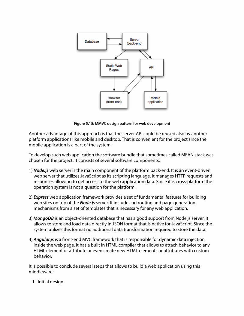
Figure 5.15: MMVC design pattern for web development !Another advantage of this approach is that the server API could be reused also by another platform applications like mobile and desktop. That is convenient for the project since the mobile application is a part of the system.
To develop such web application the software bundle that sometimes called MEAN stack was chosen for the project. It consists of several software components:
1) Node.js web server is the main component of the platform back-end. It is an event-driven web server that utilizes JavaScript as its scripting language. It manages HTTP requests and responses allowing to get access to the web application data. Since it is cross-platform the operation system is not a question for the platform.
2) Express web application framework provides a set of fundamental features for building web sites on top of the Node.js server. It includes url routing and page generation mechanisms from a set of templates that is necessary for any web application.
3) MongoDB is an object-oriented database that has a good support from Node.js server. It allows to store and load data directly in JSON format that is native for JavaScript. Since the system utilizes this format no additional data transformation required to store the data.
4) Angular.js is a front-end MVC framework that is responsible for dynamic data injection inside the web page. It has a built in HTML compiler that allows to attach behavior to any HTML element or attribute or even create new HTML elements or attributes with custom behavior.
It is possible to conclude several steps that allows to build a web application using this middleware:
1. Initial design

a. Design a data model scheme b. Design a web page layout
2. Create a web application resources structure using URL
3. Translate a web page layout in HTML breaking the layout in partial views that will be dynamically loaded according to resources structure
4. Add to HTML code elements for dynamic data binding
5. Determine front-end controllers to support dynamic data load
6. Determine back-end API and database structure
7. Write the code for data input/output in JavaScript for both front-end and back-end
5.3.2 Interface design
Figure 5.16: Web application user interface mockup

The application page consists of three parts:
1. Clients list that is vertical menu allows to browse through patients
2. Clients data block consists of patient’s personal details and list of sensors according to achieved data
3. Sensors data that has signals plots of characteristics
5.3.3 Front-end design According to the interface and data model scheme it is possible to define web application resources structure. Since the technology suppose one-page application resources structure corresponds to partial pages.
/index
|--- /index/client/:clientID
| |--- /index/:clientID/sensor/:sensorID
For each resource it is necessary to bind the data to HTML structure and define data loading controllers. Since the application is enough simple there are only three of them:
Clients Controller - loads the list of patients and add them to the menu
Client Details Controller - loads patient’s personal information and list of sensors
Sensor Controller - loads details about sensor, containing characteristic and shows live data
!5.3.4 Back-end design To operate the data at the back-end it is necessary to determine the structure of database and API. Since the MondoDB uses JSON for data notation the database structure could be determined as corresponding object schemes in JavaScript. All used schemes could be divided in to two parts: static data that is fairly stablе through application workflow and dynamic data that is continuously updating with new values.
Client schema - represents patient and it’s personal info { userID: {type:String, required: true}, bio: { name: {type:String, default: "Client Name"}, sex: {type: String, default: "male"}, age: Number } }

!Sensor schema - represents a sensor has a link to characteristics acquired by a sensor { UUID: {type:String, required: true}, name: {type:String, default: "Biomedical Sensor"}, characteristics: [{type: schema.ObjectId, ref:'Characteristic'}] } !Characteristic schema - represent biomedical characteristic has information about value { UUID: {type:String, required: true}, name: {type:String, default: "Biomedical Characteristic"}, dimension: String, dimensionShort: String, upperBound: Number, lowerBound: Number } !Sensor data schema - represents the collection of data acquired by one sensor for one patient { userID: String, sensorID: String, data: [{type: schema.ObjectId, ref:'SensorValue'}] } !Sensor value schema - represent the actual characteristic value with a timestamp { ts: {type: Date, default: Date.now()}, value: [Number] }
!!!!

The API at the back-end is supporting the web interface dynamic data load and connections from the mobile device.
/api/accept
/api/clients
/api/client/:clientID
|--- /api/client/:clientID/sensor/:sensorID
!5.3.5 Further development Since the web application developed for the prototype is pretty simple and for the moment is responsible for data visualization only there is a great field of further work. Among all the solutions it is possible to specify a number of principal directions:
1) Smart data visualization - at the moment the system allows to visualize last acquired data in a plot and show if values exceed critical bounds. The next step will be to shrink the data if the value did not change significantly. Also it is possible to add some computations like median and deviation value.
2) Accounts management and security - at the moment the server is completely open for data input/output that does not meet safety requirements/ So it is necessary to add account and session management allowing to different users access to different parts of the system.
3) Advanced notifications and report system - the system could be extended with notifications using different channels including e-mail and phone messaging.
4) Developers API - finally the system could have an open documented API that should allow to connect third-party applications to the system to operate the data.
!!!!!!!!!

6. Conclusions The usage of wearable devices is growing from day to day. In past 20 years they were mostly used in academic research and did not even reach the consumers market. Whereas now ordinary people started to be interested in such technologies and soon the wearables will get loyalty and become a part of the usual life. That became possible by means of recent wireless technologies like Bluetooth Low Energy that allows to build thumb size devices that could last on a coin size battery for more than a month. Also the popularity of mobile devices contributed in wearables development since today mobile phones are portable powerful computers that manages different areas of human life from communications to scientific researches. Wearables could extend and enrich the scope of application even more.
The idea of the work was to present a new approach in the health monitoring using the computer system that includes a wearable device part. Some similar applications are presented on the market but still have a highly specialized nature and mostly are commercially closed for extending the system with new wearable devices and new data acquisition. Whereas the approach presented in a work meets high extensibility requirements and allows to extend the system with any biomedical sensors and configure the system depending on medical needs for specific patient.
The proposed architecture of the system allows to track patient’s health state remotely from any place and distribute the health data to different services like hospitals and ambulance. That also opens opportunities in bioinformatics that does the research in a biological data analysis allowing to acquire the data directly from the network of wearable devices.
Content analysis part of the thesis was dedicated to the research in health data acquisition by wearable devices. It showed that only a small part of today’s biomedical electronic monitoring devices were adopted for portable usage. However today electronics technology allows to miniaturize them and integrate in wearable devices allowing the constant monitoring.
Design part of the work was dedicated to system prototype development. The working prototype of the system includes an electronic prototype of the wearable device and all supporting software pieces for remote monitoring. Despite the fact that the prototype presents the minimal functionality and not ready for usage it proves the whole idea of the project and has the proper architecture to support it. The prototype of the system gives a good start for the further development and final release of the real commercial product.
!!!!!

7. Bibliography [1] Mann Steve. Wearable Computing. In: Soegaard, Mads and Dam, Rikke Friis (eds.). "Encyclopedia of Human-Computer Interaction". Aarhus, Denmark: The Interaction-Design.org Foundation. 2012
[2] Cliff Randell. Wearable computing: A Review, Bristol university 2005
[3] Panos E. Kourouthanassis, George M. Giaglis, Pervasive Information Systems, M.E. Sharpe, (2008)
[4] Vital Wave Consulting (February 2009). mHealth for Development: The Opportunity of Mobile Technology for Healthcare in the Developing World [5] K. Ganapathy, Aditi Ravindira. mHealth: A potential tool for health care delivery in India, eHealth connection 2008
[6] J.D. Enderle, S. M. Blanchard, J.D. Bronzino. Introduction to biomedical engineering, Elsevier academic press 2005
[7] Sensors, Nanoscience,Biomedical Engineering, and Instruments. Series Editor, Richard C. Dorf ,University of California, Davis, Taylor and Francis.
[8] Deric P. Jones. Biomedical Sensors, Momentum press 2010
[9] E. Kniusas. Biomedical Signals and Sensors, Springer 2005
[10] R. Shiram. Continuous cuffless blood pressure monitoring based on PTT, ICBBT 2010
[11] John L. Smith. The Pursuit of Noninvasive Glucose , 2011
[12] Robin Heydon. Bluetooth Low Energy: The developer’s handbook, Prentice Hall 2013
[13] Bluetooth special interest group. Specification of the Bluetooth system v.4.0 (2010)
[14] “JSON (JavaScript Object Notation)” <www.json.org>
[15] Texas Instruments. CC2540/41 Bluetooth Low Energy Software Developers Guide
[16] “Arduino Uno Board Overview” <www.arduino.cc/en/Main/arduinoBoardUno>
[17] “Introduction to I²C and SPI protocols” <www.byteparadigm.com/applications/introduction-to-i2c-and-spi-protocols>
[18] “Pulse Sensor. Getting Started Guide” <pulsesensor.myshopify.com/pages/code-and-guide>
[19] “Apple Developers Library” <developer.apple.com>
[20] S. Holmes. Getting MEAN, Manning 2013