wear-mapping to optimise overlay coating design in rolling sliding contacts r. ahmed heriot-watt...
TRANSCRIPT

Wear-Mapping to Optimise Overlay Coating Design in Rolling Sliding Contacts
R. AhmedHeriot-Watt University, United
Kingdom

STRUCTURE of PRESENTATION
• Introduction• Design Considerations• Failure Modes• Wear Mapping• Conclusions and Future Work

TRIBOLOGICAL APPLICATIONS OF THERMAL SPRAY COATINGS
WHY THERMAL SPRAYING?
•Cost effectiveness
•Thicker coatings
•Technically competitive
•Environmental friendly
dies, shafts, rollers, gears, bearings in oil, chemical and food processing industry
COATING PROCESS ?
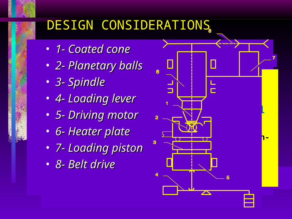
DESIGN CONSIDERATIONS
SUBSTRATE MATERIAL?
COATING MATERIAL?
COATING THICKNESS ?
M-50, 440C & Mild Steel
20 ~ 300 Micron
WC-Co & Al2O3
HVOF, APS & D-GunTRIBOLOGICAL CONDITIONS?
STRESS ?
LUBRICATION ?
SURFACE FINISH ?
(Moderate to High)
1.5 ~ 5.5 GPa
(Boundary, Mixed & Full Regime)
Dry, BF+H2O, Hitec-174, Exxon-2389
(Moderate to High)
0.5 ~ 0.05 Micron (Rq)
• 1- Coated cone1- Coated cone• 2- Planetary balls2- Planetary balls• 3- Spindle3- Spindle• 4- Loading lever4- Loading lever• 5- Driving motor5- Driving motor• 6- Heater plate6- Heater plate• 7- Loading piston7- Loading piston• 8- Belt drive8- Belt drive

SURFACE OBSERVATION –Suspended Test ( 70 million
stress cycles)
WC-Co coating (contact stress of 2.7 GPa)
Wea
r tr
ack
FAILURE MODES
• Delamination• Bulk Failure• Abrasion• Spalling
COATING
DELAMINATION
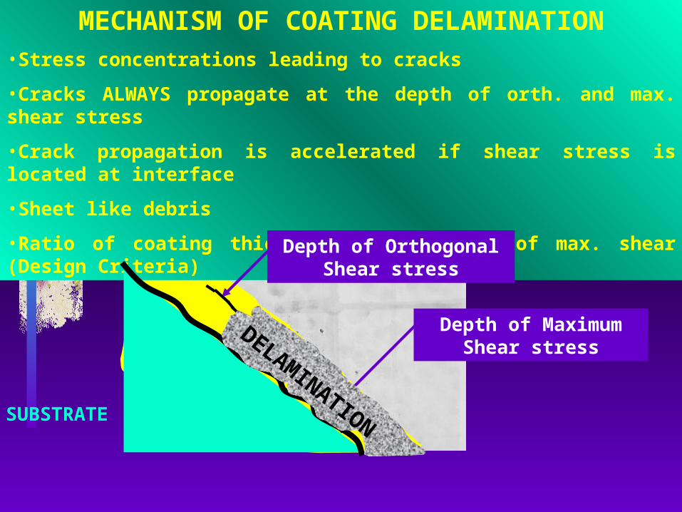
MECHANISM OF COATING DELAMINATION•Stress concentrations leading to cracks
•Cracks ALWAYS propagate at the depth of orth. and max. shear stress
•Crack propagation is accelerated if shear stress is located at interface
•Sheet like debris
•Ratio of coating thickness to the depth of max. shear (Design Criteria)
Depth of Maximum Shear stress
Depth of Orthogonal Shear stress
SUBSTRATE
DELAMINATION

INFLUENCE OF COATING THICKNESS ON COATING DELAMINATION
0
10
20
30
40
50
60
70
80
0 0.5 1 1.5 2 2.5 3
Normalised coating thickness ( = / )
Number of stress cycles (106)
Normalised pressure () = 1.5Normalised pressure () = 1.5
Normalised pressure () = 1.7Normalised pressure () = 1.7
SuspendedTests - No
Failure
BULK FAILURE
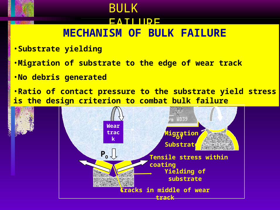
Substrate Migration to the SurfaceSubstrate Migration to the SurfaceMECHANISM OF BULK FAILURE•Substrate yielding
•Migration of substrate to the edge of wear track
•No debris generated
•Ratio of contact pressure to the substrate yield stress is the design criterion to combat bulk failure
Yielding of substrate
Migration of Substrate
Tensile stress within coating
Cracks in middle of wear track
PO
Wear track
Substrate
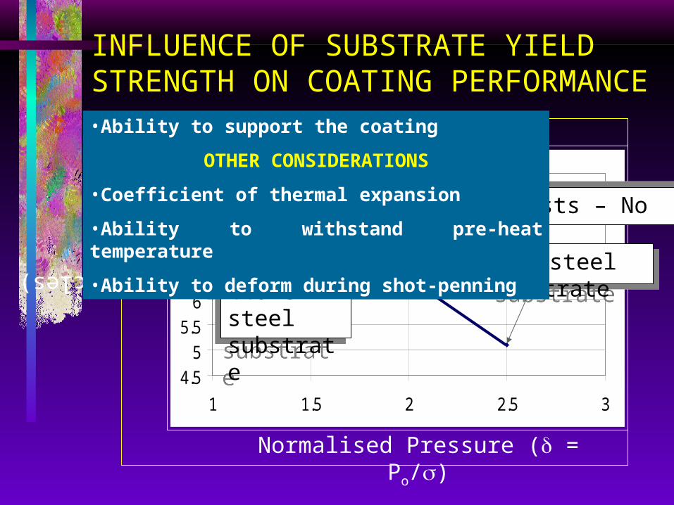
INFLUENCE OF SUBSTRATE YIELD STRENGTH ON COATING PERFORMANCE
4.55
5.56
6.57
7.58
8.5
1 1.5 2 2.5 3
Mild steel substrateMild steel substrate
Suspended tests – No failureSuspended tests – No failure
M-50 or 440-C steel substrate
M-50 or 440-C steel substrate
Normalised Pressure ( = Po/)
Log (Stress cycles)
•Ability to support the coating
OTHER CONSIDERATIONS
•Coefficient of thermal expansion
•Ability to withstand pre-heat temperature
•Ability to deform during shot-penning

DRIVE ROLLING DRIVE ROLLING ELEMENTELEMENT
DRIVEN DRIVEN ROLLING ROLLING ELEMENTELEMENT
ADHERED/ ADHERED/ EMBEDDEEMBEDDED DEBRISD DEBRIS
SMALL SMALL DEBRISDEBRIS
ASPERITY ASPERITY CONTACTCONTACT
ROLLING ROLLING DIRECTIONDIRECTION
ABRASION
MECHANISM OF COATING ABRASION•Asperity contact
•Micro-fracture leading to particle pull out
•Small wear debris lead to three body abrasion to accelerate the process
WEAR WEAR DEBRISDEBRIS
MICRO MICRO SLIP/SLIDINGSLIP/SLIDING
TRACTIONTRACTION
RATIO OF CONTACTIN
G PAIR
HARDNESS
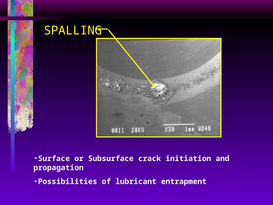
SPALLING
•Surface or Subsurface crack initiation and propagation
•Possibilities of lubricant entrapment
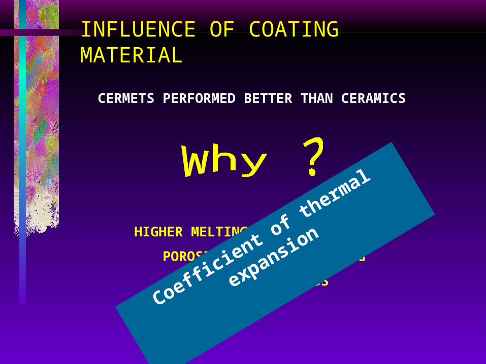
INFLUENCE OF COATING MATERIAL
CERMETS PERFORMED BETTER THAN CERAMICS
HIGHER MELTING POINT OF CERAMICS
POROSITY and MIROCRACKING
QUENCHING STRESS
Coefficient o
f therm
al expansion
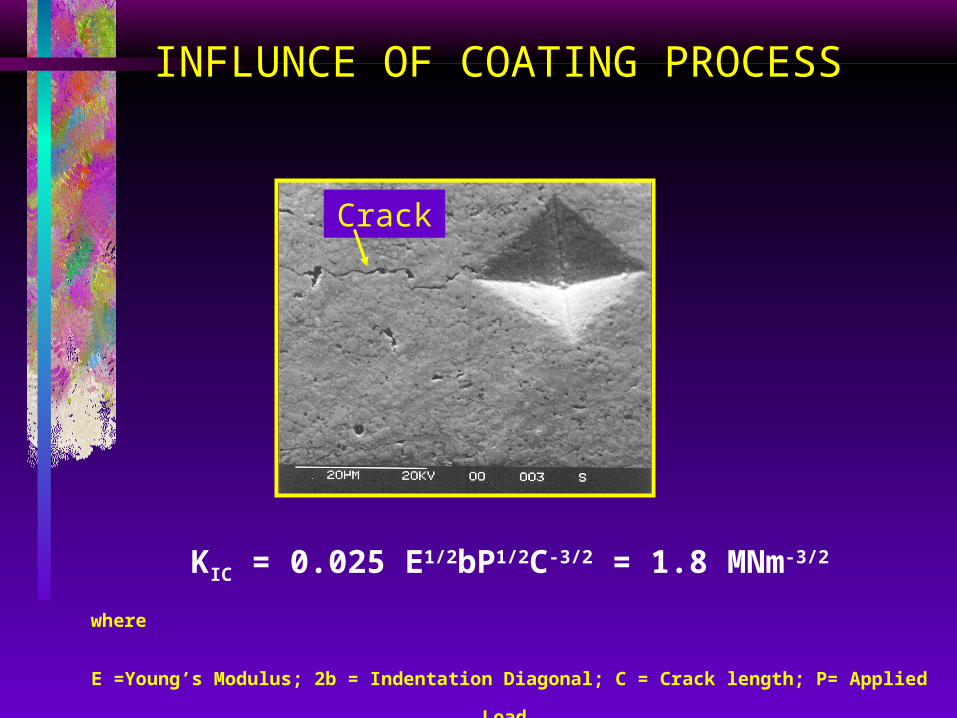
INFLUNCE OF COATING PROCESS
KIC = 0.025 E1/2bP1/2C-3/2 = 1.8 MNm-3/2
where
E =Young’s Modulus; 2b = Indentation Diagonal; C = Crack length; P= Applied Load
Crack

0
2
4
6
8
10
12
14
0 0.5 1 1.5 2 2.5 3
<3, Mixed lubrication regime
3, Full lubrication regime
Normalised Coating Thickness (=/)
Normalised Contact Pressure (=Po/)
NO FAILURE 70106 cycles
BULK FAILUREDELAMINATION
SPALLING
DELAMINATION (Cohesive)
andABRASIVE
WEAR
CohesiveAdhesive
Lubrication Regime (=Hmin/Rqa)
AB
RA
SIV
EW
EA
R
WEAR MAP OF WC-Co COATINGS (KIC 1.8 MNm-3/2)
CONCLUSIONS
• Wear map has been introduced to benchmark coating design process
• By appropriate design of coated components, it is possible to achieve a fatigue life in excess of 70 million stress cycles.
• Four failure modes I.e. Delamination, Bulk failure, Abrasion and Spalling can lead to the failure of thermal spray coatings.