wdp3-01x with oed3ftp.ruigongye.com/200804/2008050916245700001(wdp3-01xoed-en).pdf · with oed3...
TRANSCRIPT

Positioning and Sequence Control Unit for3-phase Stepping Motors
WDP3-01Xwith OED3
Doc. no. 214.157/DGB
Ident. no.: 00441110002
Edition: e220 09.2003
Software version: 03.1XX

Safety instructions
Please read the following safety instructions prior to installation, operation, maintenance and repair of the device.
• The intended use of the device under is described “Purpose” and must be observed.
• Installation, maintenance and repair of the device shall be performed by a qualified electrician.National regulations concerning – accident prevention– installation of electrical and mechanical systems– radio interference suppressionshall be observed.
• The technical data of the device, particularly the ambient conditions, shall be observed.
• The device shall only be operated by trained personnel.
• The warranty is invalidated in case of unauthorized modification or opening of the device.
• Please ask your technical consultant prior to installing accessories not listed under “Accessories”.
• The safety symbols and notes on the device and in the manual shall be observed.
Explanation of symbols
ATTENTIONReference to a danger for the device or components, possibly resulting in theendangering of human life.DANGERReference to a direct endangering of human life.
DANGERHigh voltage at component, do not touch.
DANGERHigh temperature at component, do not touch.
ATTENTIONWarning against electrostatic discharge (ESD). Only touch the PC-board or component in an electrostatically-protectedenvironment.
NOTEImportant or additional information concerning the device or the manual.

ProposalsImprovements
Berger Lahr GmbH & Co. KG WDP3-01X with OED3
Breslauer Str. 7Postfach 1180
D-77901 LahrEdition: d156 08.03Doc. no. 214.157/DGB
Sender: Please inform us, using this form, ifyou have discovered any errorswhen reading this document.We should also appreciate any newideas and proposals.
Name:
Company/department:
Address:
Telephone no.:
Proposal and/or improvements:


Table of contents
Page1 General description 1-1
1.1 Structure and characteristics 1-1
1.2 Function 1-2
1.2.1 Hardware components 1-2
1.2.2 Operating modes 1-4
1.3 Technical data 1-6
1.3.1 General data 1-6
1.3.2 Electrical data 1-6
1.3.3 Mechanical data 1-8
1.3.4 Ambient conditions 1-8
1.3.5 Regulations 1-9
1.3.6 Approvals 1-9
2 Installation 2-1
2.1 Scope of supply 2-1
2.2 Accessories 2-2
2.3 Assembly 2-3
2.4 Wiring 2-5
2.4.1 Mains connection 2-7
2.4.2 Motor connection 2-8
2.4.3 Signal interface 2-9
2.4.3.1 Signal connection pin assignment 2-10
2.4.4 RS 232 serial interface (OPT.1) 2-12
2.4.5 RS 485 serial interface (OPT.1) 2-14
2.4.6 Encoder interface (OPT.2) 2-16
2.5 Setup 2-19
2.5.1 Defaults 2-19
2.5.2 Motor test 2-21
Table of contents
WDP3-01X with OED3 Doc. no. 214.157/DGB

Page3 Operation 3-1
3.1 Controller operating modes 3-1
3.2 Switching ON 3-2
3.3 Controller STOP 3-4
3.4 Editing mode 3-4
3.5 Setting the motor phase current 3-5
3.6 Manual mode via front panel 3-6
3.7 Automatic mode 3-7
3.8 Programming 3-8
3.9 Switching OFF 3-8
4 Malfunctions 4-1
4.1 Status indicators 4-1
4.2 Troubleshooting tables 4-2
4.3 Repair work 4-5
4.4 Storage, shipment 4-5
5 Customer service 5-1
Table of contents
WDP3-01X with OED3 Doc. no. 214.157/DGB

Page6 Appendix 6-1
6.1 Device variants 6-1
6.2 Description of accessories 6-2
6.2.1 Fan 6-4
6.2.2 Mains filter 6-5
6.2.3 MP 923 interface converter 6-6
6.2.3.1 General description 6-6
6.2.3.2 Technical data 6-6
6.2.3.3 Setup 6-7
6.2.3.4 Status indicators 6-7
6.2.4 Additional bleed resistor 6-9
6.3 Glossary 6-10
6.4 Abbreviations 6-13
7 Index 7-1
8 Corrections and additions 8-1
Table of contents
WDP3-01X with OED3 Doc. no. 214.157/DGB

Table of contents
WDP3-01X with OED3 Doc. no. 214.157/DGB

1 General description
1.1 Structure and characteristics
The WDP3-01X positioning and sequence control unit, which comprisesthe OED3 operating system, can be used for controlling the followingBERGER LAHR 3-phase stepping motors:
Purpose
– with WDP3-014, motors of type size 90, (VRDM 39xx/50 LW.)– with WDP3-018, motors of type size 110, (VRDM 311xx/50 LW.)
Each unit is used for controlling one axis. The difference between thepositioning and sequence control units WDP3-014 and WDP3-018 con-sists in their power ratings.
The controller can be freely programmed using a PC and the ProOED3programming software. A PLC with integrated movement programming ispossible.An electronic gear or rotation monitoring can be implemented via theoptional encoder interface.
This documentation describes installation and operation via the frontpanel keys, the inputs/outputs of the signal interface and the encoderinterface.Programming of the device is described in the documentation of theProOED3 programming software.
Documentation
LN
PE
Serial interface (c1)for programming
and communication
230V
Motor connector
Mainsconnector
Selector switchfor mains voltage
115 VAC or 230 VAC
Status display
Front panel keys
Bleed resistor connection(only at units < RS 40)
Signal interface
Encoder interface (p2)for electronic gear
or rotation monitoring(option)
Fig. 1-1 WDP3-01X positioningand sequence control unit
with OED3
General description
WDP3-01X with OED3 Doc. no. 214.157/DGB 1-1

1.2 Function
1.2.1 Hardware components A built-in PC board in Eurocard format type size 6 HU accommodatesthe processor unit, the power controller and the power supply unit. Themost important function blocks of the unit are evident in the block diagram(fig. 1-2).
The power supply unit is a high-performance AC/DC converter which canbe connected to 115 VAC or 230 VAC supply voltages. The energyrecovered by a motor during braking can be temporarily stored up to acertain extent. To dissipate a higher amount of braking energy, anexternal bleed resistor must be connected.
Power supply unit
External bleed resistor
A DC/DC power supply unit generates various voltage levels for supplyingthe internal electronic circuits of the processor unit from the 24 VDCvoltage supply.
DC/DC power supply unit
NOTE The electronic circuitry of the processor unit consists of PELV circuits asdefined in the DIN standard VDE 0160.
Various interface configurations are possible according to the actualrequirements.
Interface configuration
NOTE The interfaces installed in the device are indicated on the type plate. Thefollowing abbreviations are used:
RS 232 Serial interface RS 232RS 485 LS Serial interface RS 485LRS 422 IN Encoder interface RS 422
WDP3-01X with OED3
Inputs
RS 232, RS 485
Outputs24 VDC
InterfaceOPT.1
Signalinterface Management
processor
Softwareindexer
(movementprofile
generator)
Rotationmonitoring
Powercontroller
Processor unit ( P control)
M
E
DC
DC
Bleed resistor
115 VAC/230 VAC
Power supply
325 VDC
AC
EEPROMFRAM
A/B or
Pulse/directionsignals (RS 422)
EncoderinterfaceOPT.2
+
Option
µ
Fig. 1-2 Block diagram
General description
1-2 WDP3-01X with OED3 Doc. no. 214.157/DGB
The signal interface carries the input and output signals as well as the24 VDC signal voltage.
Signal interface
The encoder interface RS 422 (OPT.2) can be used for implementing anelectronic gear or for rotation monitoring.
Encoder interface
The RS 232 or RS 485 serial interface can be used for programming thecontroller (in editing mode) using a PC and the ProOED3 programmingsoftware. In addition, programmed communication, e.g. with an operatingterminal, can be implemented via the serial interface (in automatic mode).
Serial interface
The management processor is used in controller automatic mode forediting the application program and addressing the corresponding inter-faces. In order to retain the application program on the controller afterdisconnecting the supply voltage, it must be written to the controller’sEEPROM using a PC and the ProOED3 programming software. In thecontroller’s FRAM, 3 variables can be stored to be retained even in caseof power failure.
Management processor
Three seven-segment displays indicate operating states and any mal-functions.
Status display
Three keys are provided on the front panel for operation and erroracknowledgement.
Keys
The indexer (movement profile generator) generates a pulse sequencefrom the current movement parameters (travel, speed and acceleration).This pulse sequence is passed on to the power controller.
Indexer
The power controller converts the pulse sequence received from the indexerinto a current pattern for controlling the 3-phase stepping motor. The motorphase current can be set on the front panel; see chapter 3.5.
Power controller
General description
WDP3-01X with OED3 Doc. no. 214.157/DGB 1-3

1.2.2 Operating modes The following operating modes can be set on the front panel.
– Manual mode via front panel– Automatic mode– Editing mode
In manual mode via front panel, you can move the motor to the left orright using the front panel keys.
Manual mode via front panel
NOTE In controller automatic mode, manual mode and teach-in mode is possiblevia the signal inputs of the controller if the corresponding application programwas loaded into the controller; see ProOED3 documentation.
In automatic mode, you can start an application program which is loadedin the controller. The application program must previously have beencreated using a PC and the ProOED3 programming software and loadedinto the controller (download).
Automatic mode
NOTE Since the controller does not have a battery-buffered main memory, theapplication program must be written to the controller’s EEPROM afterdownloading. When switching on the controller, the application programis automatically loaded from the EEPROM into the main memory of thecontroller.
In controller editing mode, you can load an application program createdwith the PC and the ProOED3 programming software on the controllerand test it in on-line mode.
Editing mode
Setting the operating modesand the motor phase current
Signalinputs/outputs
20
_ +
21OPT.1
22OPT.2
23Signal/24 V DC
24VW
U
L
N 3-phasestepping motor
Encoder
M
EPC with ProOED3
programming software
Fig. 1-3 System environment
General description
1-4 WDP3-01X with OED3 Doc. no. 214.157/DGB

Axis operating modes
In controller automatic mode, you can use the ProOED3 command“mode” in the application program to activate the following axis operatingmodes:
– Point-to-point modePositioning the axis from a given point A to a given point B at aprogrammed acceleration, speed and travel. Positioning can beeffected with absolute values (relative to a reference point) or withincremental values (relative to the current position).
– Position following mode (electronic gear) In position following mode, you can implement an electronic gearvia the encoder interface of the controller or a variable. The pulsesfed to the encoder interface or stored in the variable are multipliedwith a gear ratio and used for controlling the stepping motor.
Rotation monitoring
If the controller is equipped with an encoder interface (RS 422 IN), youcan activate motor rotation monitoring from the application program; seeProOED3 documentation. For rotation monitoring, the motor must befitted with an encoder. The rotation monitoring feature compares the setand actual positions of the motor and reports a rotation monitoring errorif the difference between set and actual position exceeds a certain limitvalue (19 steps).
General description
WDP3-01X with OED3 Doc. no. 214.157/DGB 1-5

1.3 Technical data
1.3.1 General data Power fail safe application program memory EEPROMPower fail safe memory for 3 variables FRAM
ATTENTIONAfter power-off, the contents of the FRAM variables is retained onlyfor a certain period:– at an ambient temperature of 30°C: approx. 250 days– at an ambient temperature of 50°C: approx. 60 days
Memory space for sequence program 2000 instructionsMemory space for PLC program 1000 instructions
Time for a PLC instruction approx. 1.5 ms
1.3.2 Electrical data Supply voltage, selectable 115 VAC230 VAC to 240 VAC
Mains connectionPower loss
WDP3-014 60 W max.WDP3-018 110 W max.
Mains frequency 50 to 60 Hz
Mains error protection one period
Overvoltage stability acc. to DIN VDE 0160 Class 1
Nominal power consumption WDP3-014 3.6 A at 115 VAC
2.0 A at 230 VACWDP3-018 6.5 A at 115 VAC
3.5 A at 230 VAC
Starting current 70 A max.
General description
Leakage current (IEC60990) Motor cable <5m : <10mAMotor cable 5-50m : <50mA
External fuse 6 A at 230 VAC10 A at 115 VAC
(“K” characteristic)
NOTE The devices may only be operated with fuse protection as specifiedabove. If necessary, use r.c.c.b. protection according to DIN VDE 0664,part 1/10.85.
Supply voltage 20 VDC to 30 VDCSystem supplyvia signal interface
Power consumption 1 A max.
Ripple voltage < 2 Vpp
NOTE The 24 V voltage supply must meet the specifications of the DIN standardVDE 0160 on safety extra-low voltage.
1-6 WDP3-01X with OED3 Doc. no. 214.157/DGB
Phase current WDP3-014 0.1 A to 2.5 AWDP3-018 0.1 A to 6.8 A
Motor connection
No. of steps 1000 steps per revolution
Pulse rate 40 kHz max.
Motor voltage 3 x 325 VDC (connected to mains)
Motor cable (observe EN 60204 standard) Length maximum 50 mCross-section ≥ 0.75 mm2 at cable length ≤ 30 m
≥ 1.5 mm2 at cable length > 30 m
Shield connection On both ends
Electrical characteristics of the inputsSignal interface
Polarity reversal protection, hardware debounce (settling time 0.8 ms to 1.5 ms)
Signal voltage Uhigh 15 VDC to 30 VDC
Signal voltage Ulow < 3 VDC
Input current at 24 VDC 7 mA
Electrical characteristics of the outputs
Short-circuit protected, inductive loadability
Maximum output voltage 30 VDC
Maximum switching current on output Q0 400 mA
Voltage drop at 400 mA < 2 VDC
Maximum switching current on outputs Q1 to Q3 50 mA
Voltage drop at 50 mA < 2 VDC
DANGERThe signal inputs and the 24 VDC supply voltages on the signalconnection must be definitely isolated from mains. The maximumvoltage towards ground must not exceed 60 VDC or 25 VAC.
RS 232 interface (option)Serial interfaces
Internal leakage resistance towards ground 1 Mohm
RS 485 four-wire interface (option)
Short-circuit protected 150 mA max. at short-circuit
Internal leakage resistance towards ground 1 Mohm
Supply voltage output 12 VDCfor MP 923 (10 VDC min., 18 VDC max.)
General description
WDP3-01X with OED3 Doc. no. 214.157/DGB 1-7
RS 422 IN signal level (option)Encoder interface
Short-circuit protected
Internal leakage resistance towards ground 1 Mohm
Maximum cable length 100 m
Wire cross-section 2 x 0.5 mm2 and 10 x 0.25 mm2
Shield connection On both ends
Supply voltage output 5 VDC ±5% (300 mA max.)or
12 VDC, 10 VDC min./18 VDC max. (200 mA max.)
Protection and monitoring circuits: Power amplifier overtemperature,short-circuit between motor leads (no ground fault protection), under-voltage and overvoltage
Device protection
Type of protection IP 20 acc. to EN 60529: 1991
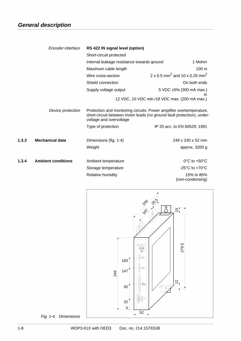
1.3.3 Mechanical data Dimensions (fig. 1-4) 249 x 240 x 52 mm
Weight approx. 3200 g
1.3.4 Ambient conditions Ambient temperature 0°C to +50°C
Storage temperature -25°C to +70°C
Relative humidity 15% to 85%(non-condensing)
52
279.
5
12
240
25.5
187 19
249
32
0
92
147
183
Fig. 1-4 Dimensions
General description
1-8 WDP3-01X with OED3 Doc. no. 214.157/DGB

1.3.5 RegulationsInsofar as the other equipment complies with the machinery direc-tive 89/392/EWG and the configuration meets the EMC testingrequirements of BERGER LAHR, conformity with the machinerydirective is hereby certified.
Machinery directive
In a configuration which meets the EMC testing requirements ofBERGER LAHR, conformity with the following standards can becertified in accordance with the EMC directive 89/336/EWG:
EMC directive
Radio interference suppression according to EN 50081-2: 1993(when using a mains filter, see Accessories)
Static discharge according to EN 60801-2: 1993, class 3
Burst according to IEC 801-4: 1988, class 4
– Use motor leads supplied by BERGER LAHR. Motor lead length is 10 m.
BERGER LAHREMC testing requirements
– Insert a mains filter supplied by BERGER LAHR into themains power supply line.
– Install the unit in a switch cabinet.– Use signal lines supplied by BERGER LAHR and wire accord-
ing to the documentation.– Run signal, mains and motor cables separately (non-parallel) and
establish a large surface area contact between the cable shieldand ground/earth.
– Install the mains filter directly at the unit. If this is not possible, usea shielded connection cable (1 m max.) between the filter and theunit.
– Establish a large surface area contact between filter/device andground (mount on a grounded metal plate or on the switch cabinetrear wall or use a ground strap).
Pursuant to the low-voltage equipment directive 73/23/EEC, theproducts are in conformity with the following standards:
Low-voltage equipment directive
Protection class 1 acc. to prEN 50178: 1994
Overvoltage Category III acc. to prEN 50178: 1994
Contamination Grade 2 acc. to prEN 50178: 1994
1.3.6 Approvals prEN 50178 classification VDE 0160/11.94
EN 60950 classification VDE 0805: 1993 + A2: 1994
UL 508 file no. 153 659
General description
WDP3-01X with OED3 Doc. no. 214.157/DGB 1-9

General description
1-10 WDP3-01X with OED3 Doc. no. 214.157/DGB

2 Installation
2.1 Scope of supply
Check that the delivery is complete.
The scope of supply (fig. 2-1) comprises:
Qty. Designation
1 Positioning and sequence control unit WDP3-014 with OED3or WDP3-018 with OED3
1 Product insert
1 Ground strap
4 Mounting bracket
1 Fan for WDP3-018 with OED3
Fig. 2-1 Scope of supply
Installation
WDP3-01X with OED3 Doc. no. 214.157/DGB 2-1

2.2 Accessories
The following accessories are available and must be ordered separately(for a description of accessories, see chapter 6.2):
– ProOED3 programming software (documentation with diskettes)
– 3-phase stepping motor
– Cable for encoder
– Fan for WDP3-018
– Motor cable 3 x 1.5 mm and 2 x 1.0 mm
– Motor cable 3 x 2.5 mm and 2 x 1.5 mm
– Mains filter
– MP 923 interface converter RS 232/RS 485
– RS 232/PC signal cable
– RS 422 IN/customer signal cable
– MP 924 interface distributor RS 485
– RS 485 LS/MP 923 signal cable
– Signal connection/customer signal cable
– Signal connection cable
– Signal cable for adapter slot option 1
– Signal cable (encoder) for adapter slot option 2
– Signal cable (pulse, direction) for adapter slot option 2
– Set of connectors (all sub-D connectors)– Electronic gear cable
NOTERefer to the sales documentation for the positioning and sequencecontrol unit WDP3-01X with OED3 for the accessory order numbers.
Installation
2-2 WDP3-01X with OED3 Doc. no. 214.157/DGB
2.3 Assembly
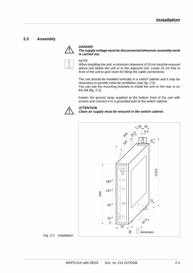
DANGER The supply voltage must be disconnected whenever assembly workis carried out.
NOTE When installing the unit, a minimum clearance of 10 cm must be ensuredabove and below the unit or to the adjacent unit. Leave 15 cm free infront of the unit to give room for fitting the cable connections.
The unit should be installed vertically in a switch cabinet and it may benecessary to provide external ventilation (see fig. 2-3).You can use the mounting brackets to install the unit on the rear or onthe left (fig. 2-2).
Fasten the ground strap supplied at the bottom front of the unit withscrews and connect it to a grounded part of the switch cabinet.
ATTENTION Clean air supply must be ensured in the switch cabinet.
52
279.
5
12
28
87.5
240
25.5
187 19
5.5
26 26
Airstream
249
320
92
147
183
Fig. 2-2 Installation
Installation
WDP3-01X with OED3 Doc. no. 214.157/DGB 2-3

The positioning and sequence control unit WDP3-014 with OED3 can beoperated without ventilation, if the minimum clearances (10 cm) areobserved.
Ventilation
The positioning and sequence control unit WDP3-018 with OED3 can beoperated without ventilation up to a phase current of 3.7 A and an ambienttemperature of 50°C.If these values are exceeded or if the status display “07” repeatedlyindicates overtemperature, the unit must be ventilated externally (fig. 2-3).
The fan on the WDP3-018 unit with OED3 must be mounted at the bottom.The airstream must pass through the unit from bottom up (see fig. 2-2). Thearrow on the fan indicates the direction of the airstream if the fan is connectedcorrectly (red = 24 VDC, black = 24 VGND).Fasten the fan with four screws at the bottom of the unit after having cutout the grille (see chapter 6.2.1). Connect the fan to the external 24 VDCvoltage supply.
Accessory fan
NOTEEnsure that the airstream in and around the unit is unobstructed.
0.1 2.0 2.4 2.7 3.1 3.4 3.7 4.1 4.4 4.8 5.1 5.4 5.8 6.1 6.5 6.8 [A]
without fan
Current
with fanfor WDP3-018
Airstream1.0 m/s
Airstream0.5 m/s
0
5
10
15
20
25
30
35
40
45
50
Adm
. am
bien
t tem
pera
ture
[C
]
Fig. 2-3 Temperature –phase current – ventilation
Installation
2-4 WDP3-01X with OED3 Doc. no. 214.157/DGB

2.4 Wiring
DANGER The supply voltage must be disconnected whenever wiring work iscarried out.
DANGER The motor connection is internally linked to the supply connection(325 V).
ATTENTION Wiring work may only be carried out in accordance with the DINstandard VDE 0105 by trained personnel.
ATTENTION Run and shield power, motor and signal cables separately.
ATTENTION Free, unassigned pins must not be wired.
ATTENTION The unit must have external fuse protection (see chapter 1.3).
ATTENTION Good heat dissipation must be ensured when installing a bleedresistor (accessory).
NOTE See chapter 1.3 for the technical data of the individual connections andinterfaces.
NOTE The interfaces installed in the device are indicated on the type plate.
NOTE The ground connections of the interfaces in adapter slots 21 and 22 areinternally interconnected.
NOTE Shield connection on both ends ensures optimum protection againstinterference for digital systems. However, it should be noted that differen-tial potentials (in particular in case of supply from different sources) maycause inadmissible currents in the shields. Such interfering currents canbe avoided by using suitable bonding conductors. The following cross-sections should be used for bonding lines: 16 mm2 Cu for bonding lines up to 200 m 25 mm2 Cu for bonding lines longer than 200 m
Installation
WDP3-01X with OED3 Doc. no. 214.157/DGB 2-5

Figure 2-4 illustrates the wiring layout of the positioning and sequencecontrol unit with the available interfaces.
Wiring layout
Communication between PC and positioning and sequence control unitis effected either through the RS 232 or the RS 485 interface, dependingon the actual interface configuration.
NOTE If the controller is provided with an RS 485 interface and the PC with anRS 232 interface, an interface converter (e.g. MP 923, see chapter 6.2.3)must be used.
MP 923 Interface converter
PC or master
RS 485/RS 422
V24/RS 232
COM 1
COM 2
22OPT.2
Encoder
Mains
21OPT.1
ME
E
R
ProOED3
Fig. 2-4 Wiring diagram
Installation
2-6 WDP3-01X with OED3 Doc. no. 214.157/DGB

2.4.1 Mains connection 1. Set the 115 V or 230 V mains voltage on the selector switch at theunit top.
ATTENTION The setting must correspond to the actual mains voltage available.
2. Mount wire end ferrules on the device end of the mains power cable.
3. Fasten three litz wires (fig. 2-5) with screws:
L Phase (115 VAC or 230 VAC)N NeutralPE Protective conductor
NOTE A mains filter can be inserted in order to shield the unit against inter-ference (see chapter 6.2.2).
→→→
L
N
PE
Fig. 2-5 Mains connection –device end
230V
Installation
WDP3-01X with OED3 Doc. no. 214.157/DGB 2-7
2-8 WDP3-01X with OED3 Doc. no.: 214.157/DGB
Installation
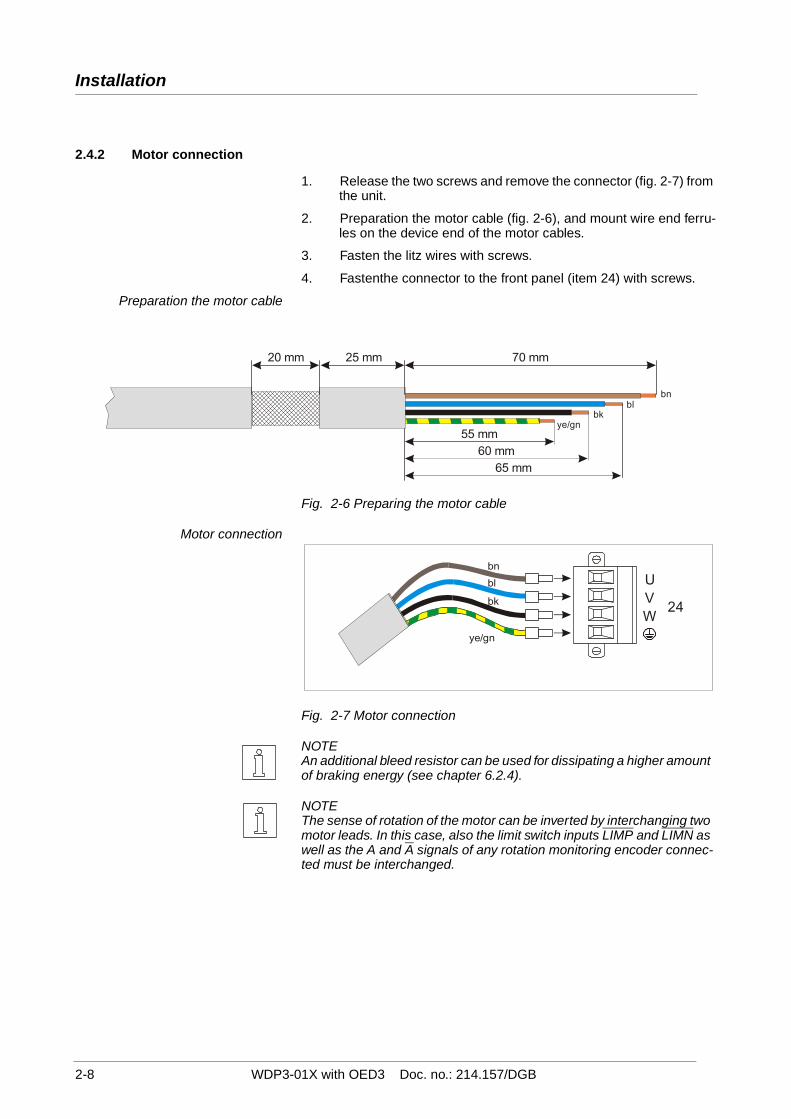
2.4.2 Motor connection
1. Release the two screws and remove the connector (fig. 2-7) from the unit.
2. Preparation the motor cable (fig. 2-6), and mount wire end ferru-les on the device end of the motor cables.
3. Fasten the litz wires with screws.
4. Fastenthe connector to the front panel (item 24) with screws.
Preparation the motor cable
Fig. 2-6 Preparing the motor cable
Motor connection
Fig. 2-7 Motor connection
NOTEAn additional bleed resistor can be used for dissipating a higher amount of braking energy (see chapter 6.2.4).
NOTEThe sense of rotation of the motor can be inverted by interchanging two motor leads. In this case, also the limit switch inputs LIMP and LIMN as well as the A and A signals of any rotation monitoring encoder connec-ted must be interchanged.
20 mm 25 mm 70 mm
55 mmye/gn
bkbl
bn
60 mm65 mm
UVW
24
bn
bl
bk
ye/gn
Installation
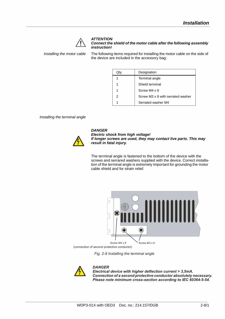
ATTENTIONConnect the shield of the motor cable after the following assembly instruction!
Installing the motor cable The following items required for installing the motor cable on the side of the device are included in the accessory bag:
Installing the terminal angle
DANGERElectric shock from high voltage!If longer screws are used, they may contact live parts. This may result in fatal injury.
The terminal angle is fastened to the bottom of the device with the screws and serrared washers supplied with the device. Correct installa-tion of the terminal angle is extremely important for grounding the motor cable shield and for strain relief.
Qty. Designation
1 Terminal angle
1 Shield terminal
1 Screw M4 x 8
2 Screw M3 x 8 with serrated washer
1 Serrated washer M4
(connection of second protective conductor)
DANGERElectrical device with higher deflection current > 3,5mA. Connection of a second protective conductor absolutely necessary.Please note minimum cross-section according to IEC 60364-5-54.
Screw M4 x 8 Screw M3 x 8
Fig. 2-8 Installing the terminal angle
WDP3-01X with OED3 Doc. no.: 214.157/DGB 2-8/1

Installation
Fastening the shield terminal The left position is provided for fastening the cable tothe fastening brak-ket.
Fig. 2-9 Fastening the shield terminal
The shield angle is suspended on the bracket from below. The motor cable is not subject to strain and securely grounds shield when installed in this way.
Fig. 2-10 Installed motor cable
UVW
24
bn
bl
bk
ye/gn
2-8/2 WDP3-01X with OED3 Doc. no.: 214.157/DGB

2.4.3 Signal interface The signal inputs I 16 to I 20 are pre-assigned ex works. The other signalinputs and outputs can be freely assigned.
1. Solder the litz wires to the connector according to the signal con-nection pin assignment table.
ATTENTION Free, unassigned pins must not be wired.
NOTE Connect system supply voltage ground to protective ground.
2. Push the shield back and fix with a cable tie.
3. Insert two bolts (fig. 2-7) into the connector shell.
4. Place the connector into the connector shell.
5. Fasten the cable and the shield to the connector shell by clampingit with the strain relief bracket.
ATTENTION Ensure good electrical contact between the shield and the connec-tor shell.Connect the shield on both ends.
6. Assemble the two parts of the connector shell with two screws.
7. Fasten the connector to the front panel (item 23) with the bolts.
DANGER All signal connections must be definitely isolated from mains. Thevoltage towards ground must not exceed 60 VDC or 25 VAC. Allsignal circuits are internally grounded via a 1 Mohm bleed resistor.
Fig. 2-7 Signal connectorassembly – device end
Installation
WDP3-01X with OED3 Doc. no. 214.157/DGB 2-9

2.4.3.1 Signal connection pinassignment
The following table shows the pin assignment of the signal connection.
Pin Assignment1* I 13: LIMN Negative limit switch
I/O supply voltage←←
2 – –3 – –4 I 11 ←5 I 10 ←6* I 14: REF Reference switch ←7 I 7 ←8 I 5 ←9 I 3 ←
10 I 1 ←11 – –12 – –13 – –14 Q 3 →15 Q 1 →16* 24VDC System supply voltage ←17* 24VDC System supply voltage ←18* IO24VDC I/O supply voltage ←19* IO24VDC I/O supply voltage ←20* I 12: LIMP Positive limit switch
I/O supply voltage←←
21 – –22 – –23* I 15: STOP Stop ←24 – –25 I 8 ←26 I 6 ←27 I 4 ←28 I 2 ←29 I 0 ←30 – –31 – –32 – –33 Q 2 →34 Q 0 →35* GND System and I/O supply voltage ground ←36* GND System and I/O supply voltage ground ←37 – –
* Minimum wiring requirement for starting up via front panel(e.g. manual movement mode).
Signal = active low I = Input Q = Output
Installation
2-10 WDP3-01X with OED3 Doc. no. 214.157/DGB
1918
1716
1514
1312
1110
98
76
54
32
1
3736
3534
3332
3130
2928
2726
2524
2322
2120
Q 3Q 2Q 1Q 024VDC24VGND
GND
IO24VDC
24VDC External power supply unit=
=
I 13 LIMNI 12 LIMP
I 11I 15 STOPI 10
I 14 REFI 8I 7I 6I 5I 4I 3I 2I 1I 0
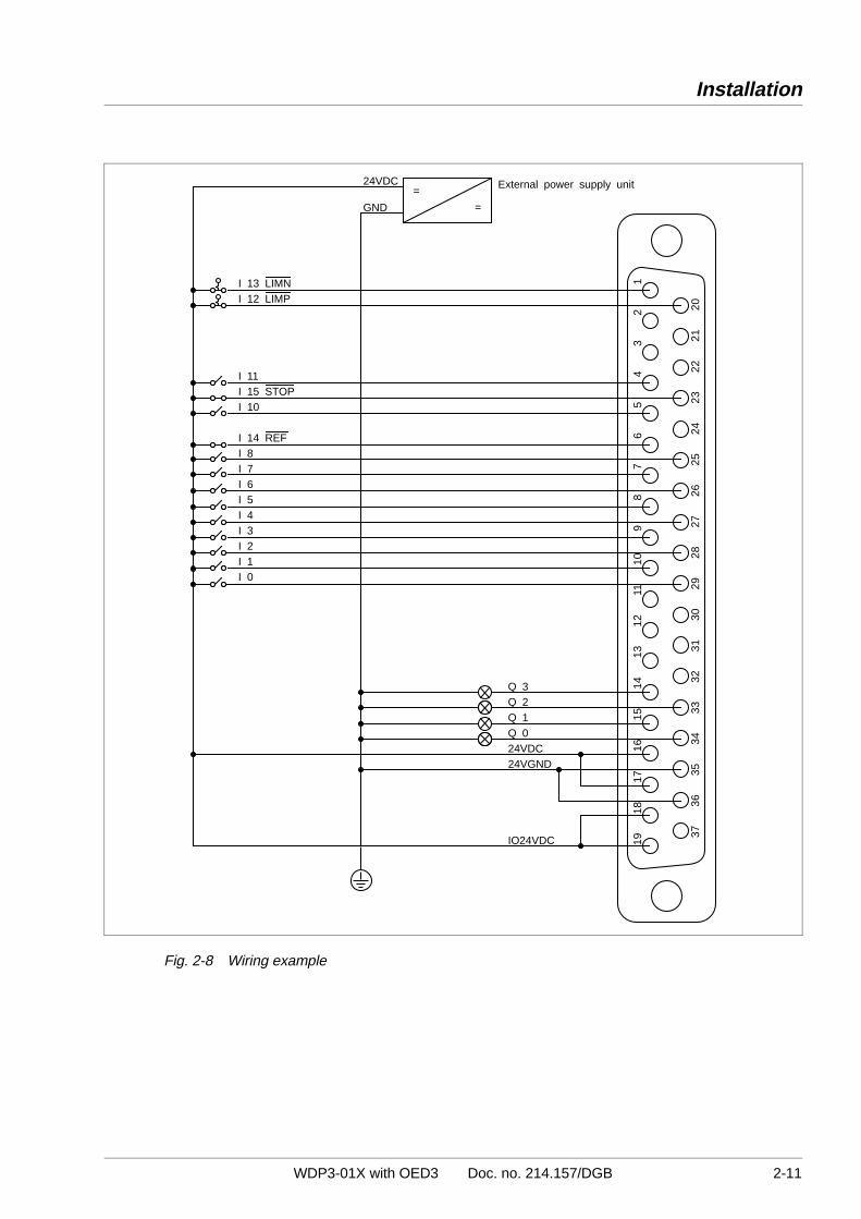
Fig. 2-8 Wiring example
Installation
WDP3-01X with OED3 Doc. no. 214.157/DGB 2-11

2.4.4 RS 232 serial interface(OPT.1)
NOTE The RS 232 serial interface is installed in adapter slot 21; see type plate.
1. Solder the litz wires to the connector in accordance with fig. 2-9and fig. 2-10.
Pin Signal Description
1 – –
2 RXD Received data ←3 TXD Transmitted data →4 – –
5 GND Ground
6 – –
7 – –
8 – –
9 – –
← Input → Output
2. Push the shield back and fix with a cable tie.
3. Insert two bolts (see fig. 2-11) into the connector shell.
4. Place the connector into the connector shell.
5. Fasten the cable and the shield to the connector shell by clampingit with the strain relief bracket.
ATTENTION Ensure good electrical contact between the shield and the connec-tor shell.Connect the shield on both ends.
6. Assemble the two parts of the connector shell with two screws.
7. Fasten the connector to the front panel (item 21) with the bolts.
ATTENTION For reasons of noise immunity, the RS 232 cable should be as shortas possible (15 m max.)!
NOTE The attachment screws of the connector shells must have M3 thread onthe device end and UNC thread on the PC end.
NOTE With an RS 232 interface, networking is not possible.
21OPT.1
Installation
2-12 WDP3-01X with OED3 Doc. no. 214.157/DGB

GND
RXD
TXD
5
4
3
2
1
9
8
7
6
Fig. 2-9 Interface connection –device end
Cable lengthmax. 15 m
Cable lengthmax. 15 m
9
8
7
6
5
4
3
2
113
1211
10
25
24
23
22
21
20
19
18
17
16
15
14
Female
Shield
Shield
Controller Controller PCPC
5
4
3
2
1
5
4
3
2
1
5
4
3
2
1
9
8
7
6
9
8
7
6
9
8
7
6
Female Female Female
Fig. 2-10 Controller/PC wiring
Fig. 2-11 Interface connectorassembly – device end
Installation
WDP3-01X with OED3 Doc. no. 214.157/DGB 2-13

2.4.5 RS 485 serial interface(OPT.1)
NOTE The RS 485 serial interface is installed in adapter slot 21; see type plate.
NOTE The serial interface is a four-wire interface.
1. Solder the litz wires to the connector as illustrated in fig. 2-12.
Pin Signal Description
1, 6 12VDC MP 923 supply voltage →2, 7 GND MP 923 supply voltage ground →3 TXD Inverted transmitted data →4 RXD Inverted received data ←5 SGND Signal ground
8 TXD Transmitted data →9 RXD Received data ←
← Input → Output
2. Push the shield back and fix with a cable tie.
3. Insert two bolts (see fig. 2-13) into the connector shell.
4. Place the connector into the connector shell.
5. Fasten the cable and the shield to the connector shell by clampingit with the strain relief bracket.
ATTENTION Ensure good electrical contact between the shield and the connec-tor shell.Connect the shield on both ends.
6. Assemble the two parts of the connector shell with two screws.
7. Fasten the connector to the front panel (item 21) with the bolts.
NOTE For a PC with RS 232 interface, the MP 923 interface converter can beused (see chapter 6.2.3).
21OPT.1
Installation
2-14 WDP3-01X with OED3 Doc. no. 214.157/DGB

5
4
3
2
1
9
8
7
6
SGND
TXD
12VDC
RXD
GND
RXD
GND
TXD
12VDC
—
—
Fig. 2-12 Interface connection –device end
Fig. 2-13 Interface connectorassembly – device end
Installation
WDP3-01X with OED3 Doc. no. 214.157/DGB 2-15

2.4.6 Encoder interface(OPT.2)
The encoder connection can be used either for rotation monitoring or foran electronic gear (position following mode).
NOTE The encoder interface is installed in adapter slot 22; see type plate.
1. Solder the litz wires to the connector as described below.Wiring
2. Push the shield back and fix with a cable tie.
3. Insert two bolts (fig. 2-14) into the connector shell.
4. Place the connector into the connector shell.
5. Fasten the cable and the shield to the connector shell by clampingit with the strain relief bracket.
ATTENTION Ensure good electrical contact between the shield and the connec-tor shell.Connect the shield on both ends.
6. Assemble the two parts of the connector shell with two screws.
7. Fasten the connector to the front panel (item 22) with the bolts.
8. Twist the encoder cable wires in pairs.
9. Establish the connection on the motor end.
ATTENTION When using 5 V encoders, –SENSE must be connected to 5VGNDand +SENSE to 5VDC on the encoder end of the cable.
NOTE The encoder signal type (pulse/direction or A/B signals) and the internalevaluation (single, double or quadruple) must be selected for an electronicgear (see chapter 6 in the ProOED3 documentation).
Fig. 2-14 Encoder connectorassembly – device end
22OPT.2
Installation
2-16 WDP3-01X with OED3 Doc. no. 214.157/DGB

Encoder interface: Encoder signal type A/B
Pin Signal Description
1 A Encoder signal A ←2 5VDC Sensor supply voltage →3 5VGND Sensor supply voltage ground →4 12VDC Sensor supply voltage →5 B Encoder signal B ←6 – –
7 TEMP_MOT Line interruption ←8 – –
9 A Encoder signal A ←10 +SENSE Sense regulator 5VDC ←11 –SENSE Sense regulator 5VGND ←12 B Encoder signal B ←13 – –
14 – –
15 – –
Signal = active low ← Input → Output
The encoder can be supplied with 12 V or from a 5 V sense regulator.
ATTENTION When using 5 V encoders, –SENSE must be connected to 5VGNDand +SENSE to 5VDC on the encoder end of the cable.
ATTENTION The TEMP_MOT input is used for detecting a line interruption. Forthis purpose, TEMP_MOT must be connected to 5VDC on theencoder.
1514
1312
1110
9
8
7
6
5
4
3
2
1 white
brownredvioletblueblackred/bluegreenyellow
grey/pink
AA5VDC+SENSE5VGND-SENSE12VDCBB
TEMP_MOT
—
—
—
Encodersignals A/B
Installation
WDP3-01X with OED3 Doc. no. 214.157/DGB 2-17
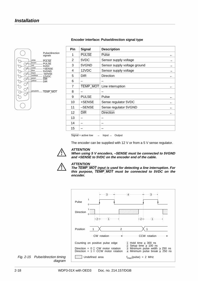
Encoder interface: Pulse/direction signal type
Pin Signal Description
1 PULSE Pulse ←2 5VDC Sensor supply voltage →3 5VGND Sensor supply voltage ground →4 12VDC Sensor supply voltage →5 DIR Direction ←6 – –
7 TEMP_MOT Line interruption ←8 – –
9 PULSE Pulse ←10 +SENSE Sense regulator 5VDC ←11 –SENSE Sense regulator 5VGND ←12 DIR Direction ←13 – –
14 – –
15 – –
Signal = active low ← Input → Output
The encoder can be supplied with 12 V or from a 5 V sense regulator.
ATTENTION When using 5 V encoders, –SENSE must be connected to 5VGNDand +SENSE to 5VDC on the encoder end of the cable.
ATTENTION The TEMP_MOT input is used for detecting a line interruption. Forthis purpose, TEMP_MOT must be connected to 5VDC on theencoder.
12 12
3 34
Pulse
Position
1
1
0
0
⇒⇒
1234
≥≥
≥≥
f (pulse) = 2 MHzmax
1 2 1
Direction
Counting on positive pulse edge
Direction = 0 CW motor rotationDirection = 1 CCW motor rotation
Hold time 300 nsSetup time 100 nsMinimum pulse width 250 nsMinimum pulse break 250 ns
CCW rotationCW rotation
Undefined areaFig. 2-15 Pulse/direction timingdiagram
1514
1312
1110
9
8
7
6
5
4
3
2
1 white
brownredvioletblueblackred/bluegreenyellow
grey/pink
PULSEPULSE5VDC+SENSE5VGND-SENSE12VDCDIRDIR
—
TEMP_MOT—
—
Pulse/directionsignals
Installation
2-18 WDP3-01X with OED3 Doc. no. 214.157/DGB
2.5 Setup
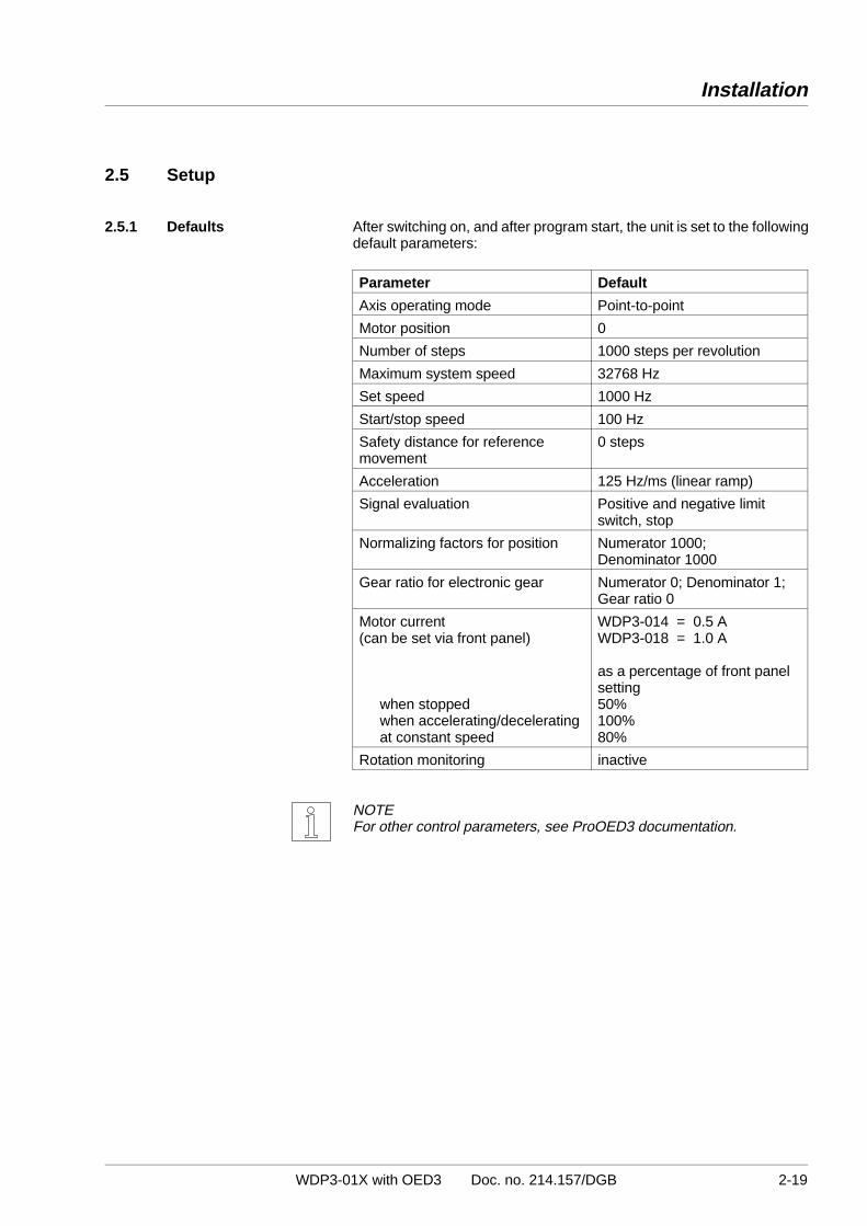
2.5.1 Defaults After switching on, and after program start, the unit is set to the followingdefault parameters:
Parameter Default
Axis operating mode Point-to-point
Motor position 0
Number of steps 1000 steps per revolution
Maximum system speed 32768 Hz
Set speed 1000 Hz
Start/stop speed 100 Hz
Safety distance for referencemovement
0 steps
Acceleration 125 Hz/ms (linear ramp)
Signal evaluation Positive and negative limitswitch, stop
Normalizing factors for position Numerator 1000; Denominator 1000
Gear ratio for electronic gear Numerator 0; Denominator 1;Gear ratio 0
Motor current (can be set via front panel)
when stoppedwhen accelerating/deceleratingat constant speed
WDP3-014 = 0.5 AWDP3-018 = 1.0 A
as a percentage of front panelsetting50%100%80%
Rotation monitoring inactive
NOTEFor other control parameters, see ProOED3 documentation.
Installation
WDP3-01X with OED3 Doc. no. 214.157/DGB 2-19

NOTE Before starting up the unit for the first time, check that the connectedmotor is suitable for the respective device variant (see chapter 6.1) andthat the controller has been wired correctly (see chapter 2.4).For starting up via the front panel, the minimum wiring requirements forthe signal interface must be observed (see chapter 2.4.3.1).
ATTENTION The mains power supply and the 24 V supply voltage of the unitmust be switched off.
1. Set the mains voltage to 115 V or 230 V, as appropriate, with theselector switch on the unit top.
ATTENTION The setting must correspond to the actual mains voltage available.
2. Check that all connectors are properly connected.
3. Switch on the power supply for the power controller.
4. Switch on the 24 V supply voltage for the processor unit. (Mains voltage and 24 V supply voltage may also be switchedon simultaneously.)
5. Press the key until “01” is displayed. The controller is now inSTOP status.
6. Set the motor phase current in accordance with the motor typeplate:
– Press the key until “01” starts flashing in the display.
– Press and hold the key and press the key several timesuntil “11” is displayed.
– Release the key. The latest selection appears flashing inthe seven-segment display: Display = Motor phase current (in A)
– Use the and keys to set the motor phase currentaccording to the motor type plate.
– Confirm and input the set value by pressing the key.
ATTENTION The set phase current must be equal to or less than the nominalphase current specified on the motor type plate (the lower the setphase current, the lower the motor torque).
230V
20
_ +
Installation
2-20 WDP3-01X with OED3 Doc. no. 214.157/DGB

2.5.2 Motor test A manual movement should be executed in order to check the motorwiring and the current settings:
– Press the key until “01” starts flashing in the display.
– Press and hold the key and press the key several timesuntil “91” is displayed.
– Release the key. An “M” starts flashing in the seven-seg-ment display.
– Move the motor in single step or continuous running mode bypressing and as appropriate:
key Clockwise rotation key Counterclockwise rotation
(as seen from front towards the motor shaft)
– Exit manual mode by pressing the key.
Single step:If you press the key only briefly, the motor performs a single step.
Continuous operation:If you keep the key pressed, the motor starts at a speed of 100 Hz.As long as you keep the key pressed, the speed increases up to4 kHz in 5 speed steps.
NOTE The sense of rotation of the motor can be changed by inverting the motorlines. If you do this, you also have to interchange the limit switch inputsLIMP and LIMN as well as the signals A and A of any connected encoderfor rotation monitoring.
NOTEFurther tests, e.g. I/O test, are available in the ProOED3 programmingsoftware; see ProOED3 documentation.
20
_ +
Installation
WDP3-01X with OED3 Doc. no. 214.157/DGB 2-21

Installation
2-22 WDP3-01X with OED3 Doc. no. 214.157/DGB

3 Operation
3.1 Controller operating modes
Processor unit status
displays
Operatingmode
Description Reference
ControllerSTOP
Program executionstopped
See chapter3.3
Editing mode Programming withProOED3 software
SeeProOED3documen-tation
Set motorcurrent
Setting the motorphase currentaccording to motortype plate
See chapter3.5
Manual mode Moving the motormanually via frontpanel keys duringdrive setup and testing
See chapter3.6
Automaticmode
Automatic programexecution
See chapter3.7
The following figure shows the major mode transitions:
Controller Stop
Editingmode
Manualmode
Set motorcurrent
Press the keys andfor approx. 3 s
Menue option“Controller/Stop”
on PC
flashing
Enter <X> and < >or select menue option“Controller/Run” on PC
↵
Automaticmode
Press and holdthe key
Press the key
Press the key
Press the keyfor approx. 3 s
Switch controller offand on again
Press the key
Fig. 3-1 Mode transitions
20
_ +
Operation
WDP3-01X with OED3 Doc. no. 214.157/DGB 3-1

3.2 Switching ON
ATTENTION The mains voltage set on the selector switch must correspond to therequired supply voltage (see type plate).
DANGER Persons or electrically conductive objects must never touch liveparts of the device or equipment.
DANGER The movement range of the equipment must be kept clear ofpersons and objects.
ATTENTION The unit must be grounded with a protective conductor.
ATTENTION The basic settings of the unit must conform to the actual require-ments; see chapter 2.5.
The following requirements must be fulfilled before switching on the unit:
Requirement ReferenceAmbient conditions in line with the technicaldata?
See chapter 1.3
Sufficient space for ventilation available? See chapter 1.3
Wiring of the unit (in particular signal inputs forlimit switches, reference switch and stop)carried out properly?
See chapter 2.4
Mains voltage set correctly on the selectorswitch?
See chapter 2.5
Motor phase current set correctly? See chapter 2.5
1. Switch on the power supply for the power controller.
ATTENTIONIf a program was loaded into the controller’s EEPROM with theProOED3 programming software, the program starts automaticallyafter power-on.You can prevent this by pressing the key while switching on.
2. Switch on the supply voltage for the processor unit (24 VDC).After power-on, the controller performs a self-test with the hard-ware and software components. Fig. 3-2 shows the power-onsequence of the controller.
Operation
3-2 WDP3-01X with OED3 Doc. no. 214.157/DGB

Copy applicationprogram fromEEPROM and
FRAM variable intoRAM, if available
Error
Switching on
Self-test
Self test error?
Yes
No
STOP
Start-up routine
RUN statusProgram execution
No
YesMinus keypressed ?
Fig. 3-2 Power-on sequence
Operation
WDP3-01X with OED3 Doc. no. 214.157/DGB 3-3

3.3 Controller STOP
The application program is stopped. To change to this status, press the key until “01” is displayed.
From this status, you can call various functions:
– Editing mode for programming the controller with the ProOED3programming software.
– Setting the motor phase current.
– Manual movement of the motor with the and keys on thefront panel.
When you set the controller to automatic mode by pressing the key,the program always starts at the beginning.
3.4 Editing mode
This operating mode is used for programming and operation with ProOED3.
Activate editing mode as follows:
1. Press the key until “01” is displayed. The controller is now inSTOP status.
2. Press and hold the key and press the key several times until“Ed” is displayed.
You can now program the controller with a PC and the ProOED3software.
NOTEFor more information, refer to the ProOED3 documentation.
20
_ +
Operation
3-4 WDP3-01X with OED3 Doc. no. 214.157/DGB

3.5 Setting the motor phase current
Since it is possible to connect various motor types to the controller, themaximum phase current must be adjusted to the motor actually connected.
1. Press the key until “01” is displayed. The controller is now inSTOP status.
2. Press the key until “01” starts flashing in the display.
3. Press and hold the key and press the key several timesuntil “11” is displayed.
4. Release the key. The latest selection appears flashing in theseven-segment display: Display = Motor phase current (in A).
5. Use the and keys to set the motor phase current according tothe motor type plate. Confirm and input the set value by pressingthe key.
ATTENTION The set phase current must be equal to or less than the nominalphase current specified on the motor type plate (the lower the setphase current, the lower the motor torque).
Operation
WDP3-01X with OED3 Doc. no. 214.157/DGB 3-5

3.6 Manual mode via front panel
Before calling manual mode, you must set the correct motor phasecurrent first; see chapter 3.5.
In manual mode, you can move the stepping motor manually using thecontroller front panel keys. You can do this either in single steps or incontinuous running mode.
Proceed as follows:
1. Press the key until “01” is displayed. The controller is now inSTOP status.
2. Press and hold the key and press the key several times until“91” is displayed.
3. Release the key. An “M” starts flashing in the seven-segmentdisplay.
4. Move the motor in single step or continuous running mode by press-ing and as appropriate:
key Clockwise rotation key Counterclockwise rotation
(as seen from front towards motor shaft)
Single step:
If you press the key only briefly, the motor performs a single step.
Continuous operation:
If you keep the key pressed, the motor starts at a speed of 100 Hz.As long as you keep the key pressed, the speed increases up to4 kHz in 5 speed steps.
5. Exit manual mode by pressing the key.
NOTE The sense of rotation of the motor can be changed by inverting the motorlines. If you do this, you also have to interchange the limit switch inputsLIMP and LIMN as well as the signals A and A of any connected encoderfor rotation monitoring.
NOTE In manual mode, all limit switches are monitored.
Operation
3-6 WDP3-01X with OED3 Doc. no. 214.157/DGB

3.7 Automatic mode
Before calling automatic mode, you must set the correct motor phasecurrent first; see chapter 3.5.
In this mode, an application program developed with the ProOED3programming software can be executed.
Program start
As a prerequisite, an application program must have been loaded intothe controller and written to the controller’s EEPROM with the ProOED3programming software.Automatic mode is automatically activated after controller power-on.In controller STOP status, the key must be pressed for approx. 3 sec.to activate automatic mode.
NOTEAn application program can also be started, stopped or tested (“debugged”)from the programming device (“on-line”).
– The program is always executed from program start.
→ A dot is displayed in the status displays.
NOTEFor more information, see ProOED3 documentation.
Operation
WDP3-01X with OED3 Doc. no. 214.157/DGB 3-7
3.8 Programming
Programming of the unit is effected in editing mode (see chapter 3.4)using the ProOED3 programming software and a PC.
Operation
3-8 WDP3-01X with OED3 Doc. no. 214.157/DGB
Documentation note
Programming an application program with ProOED3 is described in theProOED3 documentation.
3.9 Switching OFF
Switch off the supply voltages for the power controller and the processorunit.
ATTENTION The connected motor is deenergized after disconnecting the powercontroller supply voltage, i.e. it does not have any holding torque.Before disconnecting the supply voltage, ensure that any verticalloads are prevented from falling down (e.g. use motor with brake).
ATTENTION Before switching off power supply the programme transfer must be completed.Important program data will otherwise be destroyed which can only be restored by the Berger Lahr Service.
4 Malfunctions
4.1 Status indicators
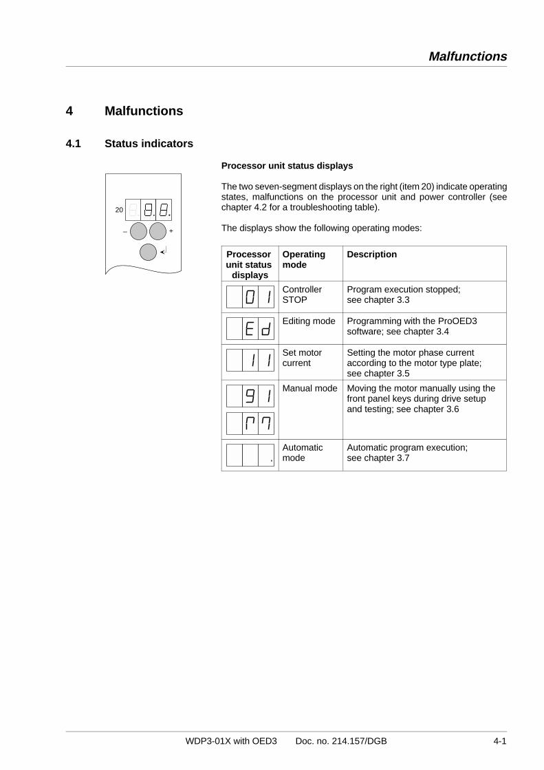
Processor unit status displays
The two seven-segment displays on the right (item 20) indicate operatingstates, malfunctions on the processor unit and power controller (seechapter 4.2 for a troubleshooting table).
The displays show the following operating modes:
Processor unit status
displays
Operatingmode
Description
ControllerSTOP
Program execution stopped; see chapter 3.3
Editing mode Programming with the ProOED3software; see chapter 3.4
Set motorcurrent
Setting the motor phase currentaccording to the motor type plate; see chapter 3.5
Manual mode Moving the motor manually using thefront panel keys during drive setupand testing; see chapter 3.6
Automatic mode
Automatic program execution; see chapter 3.7
20
_ +
Malfunctions
WDP3-01X with OED3 Doc. no. 214.157/DGB 4-1
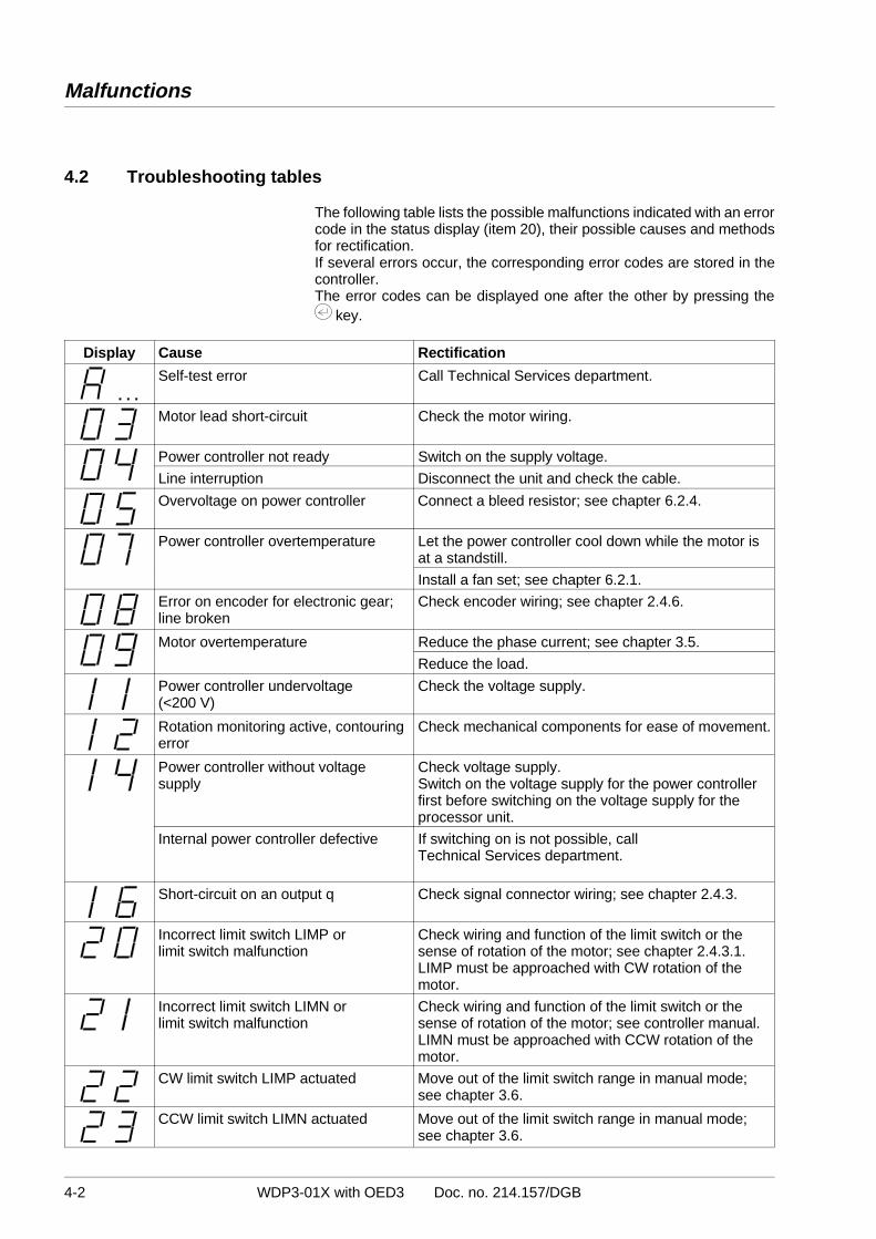
4.2 Troubleshooting tables
The following table lists the possible malfunctions indicated with an errorcode in the status display (item 20), their possible causes and methodsfor rectification.If several errors occur, the corresponding error codes are stored in thecontroller.The error codes can be displayed one after the other by pressing the
key.
Display Cause Rectification
Self-test error Call Technical Services department.
Motor lead short-circuit Check the motor wiring.
Power controller not ready Switch on the supply voltage.
Line interruption Disconnect the unit and check the cable.
Overvoltage on power controller Connect a bleed resistor; see chapter 6.2.4.
Power controller overtemperature Let the power controller cool down while the motor isat a standstill.
Install a fan set; see chapter 6.2.1.
Error on encoder for electronic gear;line broken
Check encoder wiring; see chapter 2.4.6.
Motor overtemperature Reduce the phase current; see chapter 3.5.
Reduce the load.
Power controller undervoltage(<200 V)
Check the voltage supply.
Rotation monitoring active, contouringerror
Check mechanical components for ease of movement.
Power controller without voltagesupply
Check voltage supply.Switch on the voltage supply for the power controllerfirst before switching on the voltage supply for theprocessor unit.
Internal power controller defective If switching on is not possible, callTechnical Services department.
Short-circuit on an output q Check signal connector wiring; see chapter 2.4.3.
Incorrect limit switch LIMP or limit switch malfunction
Check wiring and function of the limit switch or thesense of rotation of the motor; see chapter 2.4.3.1.LIMP must be approached with CW rotation of themotor.
Incorrect limit switch LIMN or limit switch malfunction
Check wiring and function of the limit switch or thesense of rotation of the motor; see controller manual.LIMN must be approached with CCW rotation of themotor.
CW limit switch LIMP actuated Move out of the limit switch range in manual mode; see chapter 3.6.
CCW limit switch LIMN actuated Move out of the limit switch range in manual mode; see chapter 3.6.
. . .
Malfunctions
4-2 WDP3-01X with OED3 Doc. no. 214.157/DGB

Display Cause Rectification
Reference switch defective ordisconnected
Check the reference switch.
STOP input active Deactivate the STOP input.
Internal errors:40 = Error during initialization 41 = Error in SEQUENCE component 42 = Error in PLC component
Controller errors, call Technical Services department.
OED3 operating system not found oncontroller
Call Technical Services department.
No EEPROM available Call Technical Services department.
EEPROM write error Call Technical Services department.
Error handling by application program Eliminate the error by application program; seeProOED3 documentation.
Change the control parameter “Error handling byuser” in ProOED3; see ProOED3 documentation.
Error display by ProOED3 error menue Display error with ProOED3 error menue andeliminate it; see ProOED3 documentation.
DANGER The mains supply voltage must be disconnected for any check onthe mains, motor, or bleed resistor wiring.
NOTEIf error handling is not effected by the application program, errors can beacknowledged via the front panel keys.
Malfunctions
WDP3-01X with OED3 Doc. no. 214.157/DGB 4-3

Other malfunctions
The following table lists possible malfunctions which are not displayed.
Malfunction Cause Rectification
Motor does not moveeven with currentavailable
Motor is mechanically blocked Release motor brake, if available.
No motor torque One or more motor leadsinterrupted
Check motor wiring; see chapter 2.4.2.
Motor does not move
Motor does not followcontrol
Motor leads interchanged orone or more motor leadsinterrupted
Motor and positioning andsequence control unit do notmatch
Use the appropriate motor type; see chapter 6.1.
DANGER The mains supply voltage must be disconnected for any check onthe mains, motor, or bleed resistor wiring.
Malfunctions
4-4 WDP3-01X with OED3 Doc. no. 214.157/DGB

4.3 Repair work
ATTENTION Any necessary repair work must not be carried out except byBERGER LAHR!
Mark all connections whenever disassembling the unit.
The set parameters and the mounting location number of the old unitmust be transferred to the new one when replacing a unit.
4.4 Storage, shipment
The following requirements apply when storing units or PC boards:
– The maximum air humidity must not be exceeded (see chapter 1.3).– The storage temperature specification must be observed (see
chapter 1.3).– Stored parts must be protected from dust and dirt.– Units or PC boards marked with the symbol
may only be unpacked, stored and installed in an electrostaticallyprotected environment.
– The original packing material should be kept for later use.
The following requirements apply when shipping units or PC boards:
– Units or PC boards must be shipped in their original packing material.– PC boards without batteries or accumulators must be packed in
wrapping which is electrically conductive on both sides (useoriginal wrapping, if possible).
– PC boards with batteries or accumulators must be packed inwrapping which is electrically conductive on the outside andantistatic on the inside (use original wrapping, if possible).
– Units or PC boards marked with the symbol
may only be packed in an electrostatically protected environment.
Malfunctions
WDP3-01X with OED3 Doc. no. 214.157/DGB 4-5

Malfunctions
4-6 WDP3-01X with OED3 Doc. no. 214.157/DGB

5 Customer service
The Technical Services department offer the followingservices under the phone numbers given:
– Spare part information by direct line
Phone: +49 (0) 7821 - 946 - 606
Express spare part shipment from Lahr; reaches most destinations in Europe within 24 hours.
– Technical advice in case of failures by hotline
Phone: +49 (0) 7808 - 943 - 226
Fax: +49 (0) 7808 - 943 - 499
Internet e-mail: [email protected]
Of course, the Technical Services department also offer the followingservices:
– On-site maintenance and
– direct communication with your service specialist.
Customer service
WDP3-01X with OED3 Doc. no. 214.157/DGB 5-1

Customer service
5-2 WDP3-01X with OED3 Doc. no. 214.157/DGB
6 Appendix
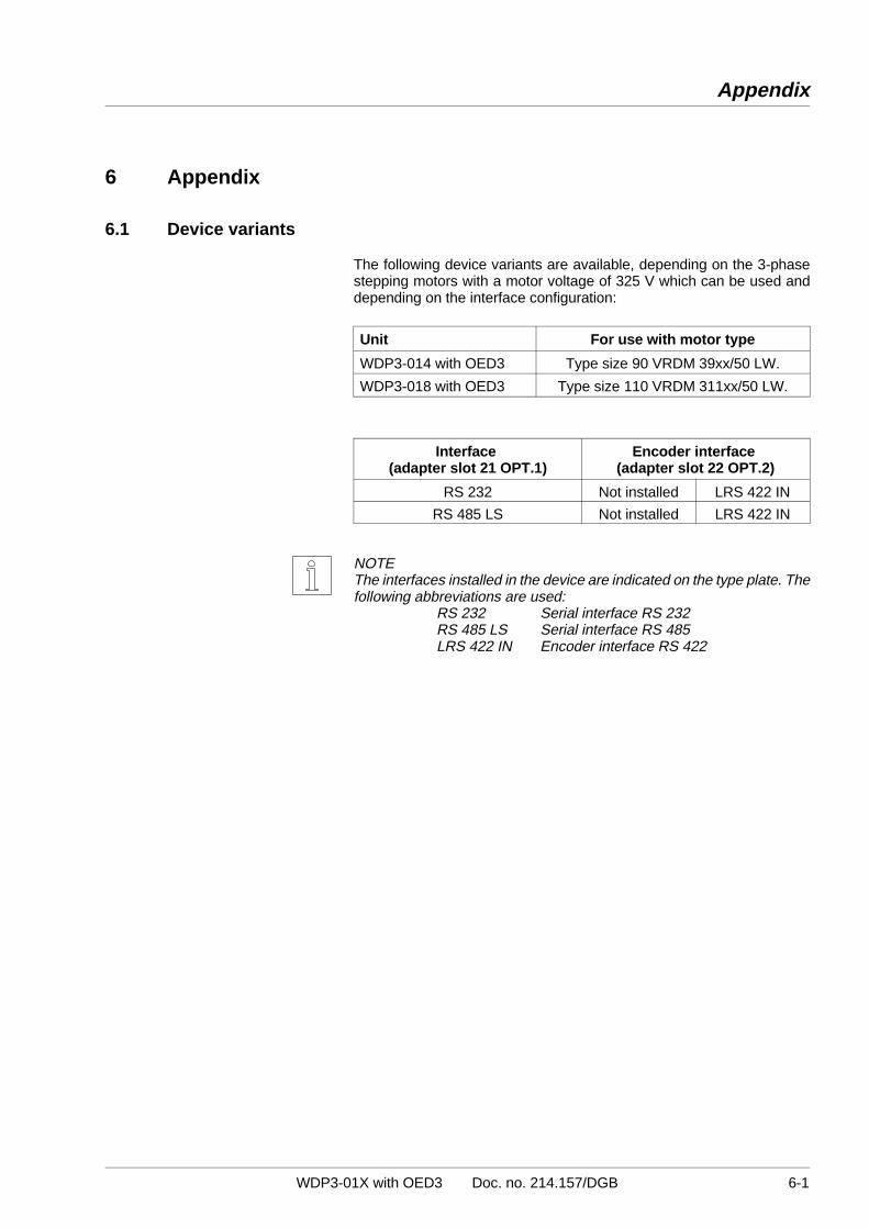
6.1 Device variants
The following device variants are available, depending on the 3-phasestepping motors with a motor voltage of 325 V which can be used anddepending on the interface configuration:
Unit For use with motor type
WDP3-014 with OED3 Type size 90 VRDM 39xx/50 LW.
WDP3-018 with OED3 Type size 110 VRDM 311xx/50 LW.
Interface (adapter slot 21 OPT.1)
Encoder interface (adapter slot 22 OPT.2)
RS 232 Not installed LRS 422 IN
RS 485 LS Not installed LRS 422 IN
NOTE The interfaces installed in the device are indicated on the type plate. Thefollowing abbreviations are used:
RS 232 Serial interface RS 232RS 485 LS Serial interface RS 485LRS 422 IN Encoder interface RS 422
Appendix
WDP3-01X with OED3 Doc. no. 214.157/DGB 6-1

6.2 Description of accessories
Mains
8
11
9
157
10
12 13
5
3
2
6
1
6
14
4
6
6
Fig. 6-1 Accessories
Appendix
6-2 WDP3-01X with OED3 Doc. no. 214.157/DGB

The following accessories may be ordered separately (see fig. 6-1):
Item no. Designation Reference
1 3-phase stepping motor with or without encoder See chapter 6.1 and 3-phasestepping motor drives catalogue
2 Fan for WDP3-014 See chapter 6.2.1.
3 Mains filter See chapter 6.2.2.
4 MP 923 interface converter RS 232/RS 485 See chapter 6.2.3.
5 Additional bleed resistor See chapter 6.2.4.
6 Set of connectors (all sub-D connectors)
See sales documentation
Non-terminated cables
7 Cable for encoder
8 Motor cable 3 x 1.5 mm and 2 x 1.0 mm Motor cable 3 x 2.5 mm and 2 x 1.5 mm
9 Signal cable for signal connection
10 Signal cable for serial interface
11 Motor encoder cable
Ready-made cables
12 RS 232/PC signal cable, terminated on both ends
13 RS 422 IN/customer signal cable, terminated on device end
14 RS 485 LS/MP 923 signal cable, terminated on both ends
15 Signal connection/customer signal cable, terminated ondevice end
Non-terminated cables are available in the following lengths:
5 m 10 m 15 m 20 m 25 m 30 m 50 m 75 m 100 m 200 m
Ready-made cables are available in the following lengths:
1.5 m 2 m 3 m 5 m
NOTERefer to the sales documentation for the positioning and sequencecontrol unit WDP3-01X with OED3 for the accessory order numbers.
Appendix
WDP3-01X with OED3 Doc. no. 214.157/DGB 6-3

6.2.1 Fan The unit can be provided with a fan in order to improve heat dissipation(see chapter 2.3).
The fan (fig. 6-2) must be mounted at the bottom of the unit.The airstream must pass through the unit from bottom up (see fig. 2-2). Thearrow on the fan indicates the direction of the airstream if the fan is connectedcorrectly (red = 24 VDC, black = 24 VGND).
1. Cut out the grille on the unit.
2. Fasten the fan to the bottom of the unit with four screws.
3. Connect the fan to the external 24 VDC voltage supply.
NOTE Ensure that the airstream in and around the unit is unobstructed.
402844
32
32
40Fig. 6-2 Fan
Appendix
6-4 WDP3-01X with OED3 Doc. no. 214.157/DGB

6.2.2 Mains filter A mains filter (fig. 6-3) can be inserted into the mains supply line for radiointerference suppression.
NOTE When connecting the mains filter, the EMC testing specifications ofBERGER LAHR must be observed.
Ambient conditions
Storage temperature -25°C to +70°C
Operating temperature 0°C to +55°C
Humidity class F acc. to DIN 40040
Humidity class, tested to IEC 68 part 2-3 at:Air temperature +40°C, +2°CRelative humidity 93%, +2%, -3%non-condensing
N’
N
Mains
L’
L
PE
PE
→→→
L
N
PE
Fig. 6-3 Mains filter
Appendix
WDP3-01X with OED3 Doc. no. 214.157/DGB 6-5

6.2.3 MP 923 interfaceconverter
6.2.3.1 General description The MP 923 interface converter is used for data transmission from anRS 485 LS (RS 422) interface to a V24 (RS 232) interface and vice versa.
The interface converter must be powered either via the power supply unitconnection (2-pin female diode connector) or via the RS 485 (RS 422)connector with 12 VDC. With BERGER LAHR positioning units (e.g.WDP3), power is supplied via the RS 485 (RS 422) connection.
6.2.3.2 Technical data Electrical data
Voltage supply 9.6 to 15 VDC/150 mA
Interfaces RS 485 LS (RS 422)V24 (RS 232)
Mechanical data
Dimensions 97 x 65 x 30 mm
Weight approx. 130 g
Ambient conditions
Storage temperature -25°C to +70°C
Operating temperature 0°C to +55°C
Humidity class F acc. to DIN 40040
Humidity class, tested to IEC 68 part 2-3 at:Air temperature +40°C, +2°CRelative humidity 93%, +2%, -3%non-condensing
MP923
POWER
ON
RS485
V24
Fig. 6-4 MP 923 interfaceconverter
Appendix
6-6 WDP3-01X with OED3 Doc. no. 214.157/DGB

6.2.3.3 Setup 1. Wire the MP 923 interface converter in accordance with fig. 6-5.
NOTE The MP 923 is supplied with 12 VDC power via the RS 485 (RS 422)connector of the BERGER LAHR controller.
ATTENTION The interface cables must be shielded on both ends via the connec-tor shells!
ATTENTION For reasons of noise immunity, the V24 (RS 232) cable should be asshort as possible (15 m max.)!
2. Switch on the mains voltage.→ The LED “POWER ON” lights up. The two other LEDs remain
dark.
3. Start data transmission.→ Depending on the sense of the data transmission, either the
LED marked “RS 485 → V24” or the LED marked “RS 485 ←V24” lights up.
6.2.3.4 Status indicators The status indicators show the operating status or any malfunction.
LED Lit Not lit Flashing
“POWER ON” Supply voltage available Supply voltage notavailable
“RS 485 → V24” RS 485 (RS 422) interface incorrectly wired (signal lines TxD (TxD) andRxD (RxD) interchanged)
No data transmissionfrom RS 485 (RS 422)to V24 (RS 232)
Data transmission from RS 485 (RS 422) toV24 (RS 232) enabled
“RS 485 ← V24” V24 (RS 232) interface incorrectly wired (pins 2and 3 interchanged)
No data transmissionfrom V24 (RS 232) to RS 485 (RS 422)
Data transmission fromV24 (RS 232) to RS 485 (RS 422)enabled
Appendix
WDP3-01X with OED3 Doc. no. 214.157/DGB 6-7

V24or
RS 232
Cable length15 m max.
1312
1110
98
76
54
32
1
2524
2322
2120
1918
1716
1514
Maleconn.
V24or
RS 232
Cable length15 m max.
Shield
Shield
Signalground
Signalground
1312
1110
98
76
54
32
1
2524
2322
2120
1918
1716
1514
1312
1110
98
76
54
32
1
2524
2322
2120
1918
1716
1514
Maleconn.
Femaleconnector
RS 485 LSor
RS 422 RGND
GND+12V
RxDTxD
RxDTxD
54
32
1
54
32
1
98
76
98
76
Femaleconnector
Femaleconnector
MP 923
RS 485/RS 422 V24/RS 232
Fig. 6-5 MP 923 interfaceconverter setup
Appendix
6-8 WDP3-01X with OED3 Doc. no. 214.157/DGB

6.2.4 Additional bleed resistor The additional bleed resistor FZP 200 (180 ohms, 150 W) can be usedfor dissipating a major amount of braking energy (fig. 6-6).
DANGER High voltages are present at the bleed resistor connections (approx.325 VDC).
DANGER The bleed resistor heats up when a great amount of braking energyis produced.
ATTENTION Good heat dissipation must be ensured when installing the bleedresistor.
1. Switch the mains voltage OFF.
2. Provide the two bleed resistor leads with wire end ferrules on thedevice end.
3. Connect the two litz wires to the terminals at the bottom of the unit.
B+ WDP3-01XB-
1822
010
0
90
4.5
65
Fig. 6-6 Additional bleed resistor
Appendix
WDP3-01X with OED3 Doc. no. 214.157/DGB 6-9
(only at units < RS 40)

6.3 Glossary
Absolute dimensionsRefers to a system of dimensions for positioning operations. Thereference point for positioning is the reference point of the system.
Absolute positioningFor absolute positioning, the position value refers to the zero pointof the axis.
CCW rotationSense of rotation of the motor in a counterclockwise direction (asseen from front towards the motor shaft).
CommandsThe functions of a controller are accessed using commands.Commands are sent from the master to a controller (slave). Thecontroller interprets and executes the commands.
CW rotationSense of rotation of the motor in a clockwise direction (as seenfrom front towards the motor shaft).
DownloadWith the download function, data are loaded into the controllerfrom a master computer.
Electronic gearExternally supplied pulses are counted as A/B encoder signals orpulse/direction signals and multiplied with a gear ratio. Thesepulses are used as the reference variable for stepping motorpositioning.
EncoderSensor for motor position detection (actual position detection).
Encoder signals A/BPulse signals of an encoder. For one motor revolution, a definednumber of pulse signals (e.g. 1000) is generated by the encoder.The encoder signals are subjected to single, double or quadrupleevaluation.
Appendix
6-10 WDP3-01X with OED3 Doc. no. 214.157/DGB

Gear ratioMultiplication factor for positioning operations, which is composedof a numerator and a denominator (step-down gearing or step-upgearing).
Incremental (relative) dimensionsRefers to a system of dimensions for the positioning unit. Thereference point for positioning is the current position.
Inputs/outputsThe controller is provided with a certain number of inputs andoutputs through which sequential operations are controlled.
Limit switchSwitch for limiting the travel and for reference movements.
Master/slave principlePrinciple of communication in a network.Only the master is permitted to send commands. Slaves onlyreceive and execute commands.
Negative limit switchLimit switch in CCW (counterclockwise) direction. Motor rotationin a counterclockwise sense as seen from front towards the motorshaft.
Network modeAn operating mode used for a network of positioning units. Severalunits are connected to a host via a physical link. Selection of theunits to be addressed is effected by a device polling command.
Positive limit switchLimit switch in CW (clockwise) direction. Motor rotation in aclockwise sense as seen from front towards the motor shaft.
Power controllerA motor is controlled by a power controller. The power controllerconverts positioning signals from the processor control into signalsfor motor control.
Pulse/direction signalsSignals for reference variable input for an electronic gear.
Appendix
WDP3-01X with OED3 Doc. no. 214.157/DGB 6-11
Reference movementMotor movement towards the CCW or CW limit switch or areference switch for setting a reference point for the system ofdimensions.
Reference pointPosition value after a reference movement or after setting thereference point.
Reference speedThe reference speed is the speed at which the axis moves awayfrom a limit switch.
Reference switchA switch which can be approached from either direction for areference movement.
Relative positioningFor incremental positioning, the position value refers to the currentposition of the axis.
Rotation monitoringRotation monitoring is used for detecting positional deviations ofmotor movements. The actual position is detected by an encoderand then compared with the setpoint. If the difference betweenactual and set position exceeds a preset value, a contouring erroris reported and the motor is decelerated.
RS 485 interfaceSerial interface for a network configuration.
Teach-inThe teach-in function is used for storing positions which have beenapproached by manual control.
UploadThe upload function is used for reading data from the controller.
Appendix
6-12 WDP3-01X with OED3 Doc. no. 214.157/DGB
6.4 Abbreviations
AC Alternating Current
ASCII American Standard Code for Information Interchange
DC Direct Current
Doc. no. Documentation number
DP Decentralized peripheral equipment
E Encoder
FI Fault current
HU Height Unit
I Input
I/O Input/Output
IBS Interbus-S interface
LED Light Emitting Diode
M Motor
PBDP Profibus-DP interface
PC Personal Computer
PELV Protected Extra Low Voltage
PLC Programmable Logic Controller
Q Output
Appendix
WDP3-01X with OED3 Doc. no. 214.157/DGB 6-13

Appendix
6-14 WDP3-01X with OED3 Doc. no. 214.157/DGB

7 Index
A
Acceleration 2-19
Accessories 2-2, 6-2
Application mode 3-7
Application program 3-7
Automatic mode 1-4
Axis operating modes
Point-to-point mode 1-5
Position following mode 1-5
C
Connections
Encoder interface 1-8, 2-16
Mains connection 1-6, 2-7
Motor connection 1-7, 2-8
RS 232 serial interface 1-7, 2-12
RS 485 serial interface 1-7, 2-14
Signal interface 1-7, 2-9
D
Defaults 2-19
Displays
Luminous displays 4-1
E
Editing mode 1-4
Encoder signal type
A/B signals 2-17
Pulse/direction 2-18
Error code 4-2
F
Front panel 1-1
Index
WDP3-01X with OED3 Doc. no. 214.157/DGB 7-1

M
Malfunctions 4-2
Manual mode 1-4
via front panel 1-4
Motor current reduction 2-19
N
Normalizing factors 2-19
Number of steps 2-19
O
Operating modes 3-1
R
Rotation monitoring 1-5
S
Set speed 2-19
Start speed 2-19
System speed 2-19
T
Timing diagram
Encoder signals A/B 2-17
Pulse/direction 2-18
V
Ventilation 2-4
W
Wiring layout 2-6
Index
7-2 WDP3-01X with OED3 Doc. no. 214.157/DGB

8 Corrections and additions
At present there are no corrections or additions.
Corrections and additions
WDP3-01X with OED3 Doc. no. 214.157/DGB 8-1

Corrections and additions
8-2 WDP3-01X with OED3 Doc. no. 214.157/DGB