wcs75hdz - webtool-
TRANSCRIPT

Allspeeds Ltd. Royal Works, Atlas St
Clayton le Moors Accrington Lancashire
England BB5 5LW
Tel +44 (0)1254 615100
www.allspeeds.co.uk
WIRE ROPE CUTTER WCS75HDZ
PRODUCT CODE No. 980482
INSTRUCTIONS FOR INSTALLATION, OPERATION & MAINTENANCE
Revision 9 issue 2. Modification No. 20644 Date 23rd. Oct 2013
© Copyright Allspeeds Holdings Ltd. This document must not be modified in any way.

Page 2 of 13
Description
The WCS75HDZ is a double acting tool primarily intended for use on steel wire rope, having a maximum tensile strength of 1770N/mm and will cut ropes up to 75mm diameter. It may be used on alternative materials, such as electrical power or communication cables, again up to a maximum of 75mm diameter. 1. SAFETY Before operation, read and understand this operations manual. Whilst the tool is intended for remote or local operation sub-sea, there is no reason why it should not be used above surface. Ensure that the tool, hoses and pump are in good condition and properly connected. Ensure that suitable pressure regulation equipment is used and that the unit is not subjected to pressures higher than those stated in section 3 In all cases, where an operator is present, the safety aspects must be reviewed before the cutting operation is commenced. No attempt should be made to cut wire ropes or other material that is under tension. Ensure that the operator is shielded from the cutting blade during the cutting operation. When cutting near the very end of hose or rope, individual cut wires can be expelled from the tool, please ensure that the operator is shielded from these. If in doubt please contact the manufacturer (Allspeeds Ltd) or an authorized distributor for assistance. If at any time it is necessary to carry out proof tests on the tool, e.g. after service on the hydraulic cylinders, it must be returned to the supplier for testing where the following procedures apply. The maximum proof test pressure should not exceed 125% of the maximum working pressure and this should only be done by Allspeeds using our specially adapted test rig. The tool should be guarded during the proof test operation, and be carried out in a safe working environment. The proof pressure should be applied gradually, until the maximum pressure is reached.

Page 3 of 13
INSPECT THE TOOL BEFORE USE With the cutter isolated from the hydraulic supply, check the condition of the blade edge. If the blade is damaged or blunt replace with a fresh blade before cutting. This procedure is as described in section 8. Ensure that care is taken when checking the blade as the edge may be sharp Check the condition of the anvil. It is normal that the anvil will show an indent where the blade has pressed down into it and can withstand multiple cuts, but any excessively damaged anvil should be replaced. This procedure is as described in section 7 Ensure that all retaining bolts are tight
CAUTION – USE OF BLADES AND PARTS NOT APPROVED BY WEBTOOL MAY RESULT IN TOOL FAILURE AND CONSEQUENTIAL DAMAGE
2. CUTTING CAPACITY The cutter is primarily intended for use on steel wire rope, having a maximum tensile strength of 1770N/mm and will cut ropes up to 75mm diameter. It may be used on alternative materials, such as electrical power or communication cables, again up to a maximum of 75mm diameter. Where smaller diameters are to be cut, effort should be made to place the material centrally along the anvil to minimise any offset loading. This cutter is not intended for use on chain or solid steel bar.
3. INSTALLATION Four tapped Holes, M10 x20mm deep, are provided in the tool body (see sketch) which can be used for any attachment necessary to mount the cutter. The cylinder is a pressure vessel and is not recommended as a mounting point, the cylinder should not be drilled, machined, mutilated or damaged in any way, any warranty could be invalidated by such actions.

Page 4 of 13
A hydraulic supply is required, ported as shown (see sketch). The maximum working pressures are shown in the table 1 below and pressure limiting valves must be fitted into the supply to limit the pressures to these levels.
A relief valve should also be incorporated in the return line. This is to prevent excessively high pressures in the annular side of the hydraulic cylinders should the return to tank become blocked for any reason. The oil supply must be clear and free from contamination. A good quality ISO32 grade hydraulic oil, e.g. Shell Tellus 32 or equivalent, is suitable.
The weight of the tool is 46.5kg. TABLE 1.
Function Working Pressure Swept Volume
psi bar ml. U.S. Gallon
Working Stroke 10,000 700 750 (0.197)
Return Stroke 2,750 190 490 (0.130)
Auxillary Stroke 2,750 190 80 (0.021)
Please note: For the main ram the max working pressure and max return stroke pressure is
700 bar

Page 5 of 13
4. OPERATION
Before deployment, function test the tool and ensure that all operators are familiar with this procedure. ROV observation of the tool should be maintained at all time during operation. Prior to use, ensure no damage has occurred to the blade or anvil. Ensure the anvil is fully retracted. DEPLOYMENT Place the cutter over the wire rope. Ensure that the wire rope is as far into the cutter as possible.
Pressurize the anvil cylinder to fully extend the anvil, thus retaining the wire rope in the body of the tool. Check visually that the anvil is fully home, this is important to prevent damage to the tool (The end of the anvil should just be proud of the body of the tool on the opposite face to the anvil cylinder).

Page 6 of 13
Operate the main ram power port to sever the wire rope, hold pressure until the wire rope is severed. Once the wire is severed, pressurize the main ram retract port to withdraw the cutting blade. Then, and only then, retract the anvil. It is important not to operate the anvil cylinder whilst the main ram and blade are in the fully extended position. If a further cut is required, the above procedure should be repeated. TROUBLESHOOTING If the rope does not cut through completely on the first attempt, cycle the blade by retracting it slightly and then attempting the cut again. If the rope does not completely cut after multiple cycles of the blade, check the input pressure to the main input of the cylinder. This can be a maximum of 700 bar (10,000psi). If the rope to be cut is still not severed after multiple cycles and at a pressure of 700 bar, retract the blade and then the anvil and return the tool to the surface for inspection of the blade and anvil, replace if necessary. IMPORTANT NOTE – ENSURE THAT THE BLADE IS FULLY RETRACTED AND THAT ALL PRESSURE TO THE CUTTER IS RELIEVED AS IT IS RAISED TO THE SURFACE. FAILURE TO DO THIS CAN LEAD TO A DANGEROUS BUILD UP OF PRESSURE IN THE CYLINDER.

Page 7 of 13
5. AFTER USE
When the tool is retrieved from a marine enviroment, it should be hosed off with clean water, allowed to drain and sprayed externally with a de-watering fluid. Before storage, inspect the general condition of the tool. Particular attention should be paid to the anvil and blade. The anvil should be clean and free from any damage, The blade edge should be smooth and free from any serrations. Note that a slight ripple to the blade edge is acceptable and will not cause problems. Any minor damage can be smoothed off with an oil stone if necessary.
IMPORTANT – DO NOT STORE THE TOOL WITH A COMPLETELY SEALED CYLINDER AS PRESSURE MAY BUILD UP DUE TO TEMPERATURE CHANGES.
6. SERVICE
IMPORTANT – ENSURE THERE IS NO HYDRAULIC PRESSURE IN THE CYLINDER BEFORE PERFORMING ANY SERVICE OR MAINTENANCE PROCEDURES ON THIS CUTTER
It is unlikely that service would be required on the hydraulic components of the tool under normal circumstances, but a seal spares kit is available if required. The only parts that would need intermittent replacement would be the anvil and blade, depending on the frequency of use and materials being cut. These parts can be ordered up on the following spares reference numbers, but in addition please quote the tool serial number. Seal Kit main power cylinder only Part Number 995119 Seal Kit anvil cylinder only Part Number 995122 Seal kit for main cylinder and anvil Part number 995123 Anvil Part Number WC6377 Blade Part Number 705009c Blade Retaining Pin Part Number 030648 2 off We advise that any servicing should be carried out by an authorised distributor only. If required, the tool can be returned to the manufacturer (Allspeeds Ltd) or an authorized distributor for servicing and testing. If servicing is to be undertaken by the user, please see note on proof testing under SAFETY (Chapter 3), and the following:- All servicing operations should be carried out in a clean environment to prevent contamination of the oil and mating components. Care should be taken with all mating areas ie. threads and sealing faces, as any damage or abrasive contamination could cause galling or seizing on re-assembly. Please note that we coat the stainless steel cylinders with a titanium nitride coating to prevent galling, however, a suitable anti-galling paste should be used (we recommend Swagelok Silver Goop) on all stainless steel threads. The cylinder is a pressure vessel and should not be drilled, machined, mutilated or damaged in any way for mounting purposes or to assist in its removal for servicing, any warranty could be invalidated by such actions. Also see section 9 The use of stilsons to remove the cylinder is not recommended as damage will occur.

Page 8 of 13
7. REPLACEMENT OF THE ANVIL
Loosen and remove the four screws 035118. The cylinder body 728067 will now pull free. The anvil WC6377 may now be unscrewed from the piston 764105. The piston may now be removed from the anvil seal housing 749046, all seals are now accessible. The anvil can now be removed.
Re-assembly is the reverse of the above process.
Page 9 of 13
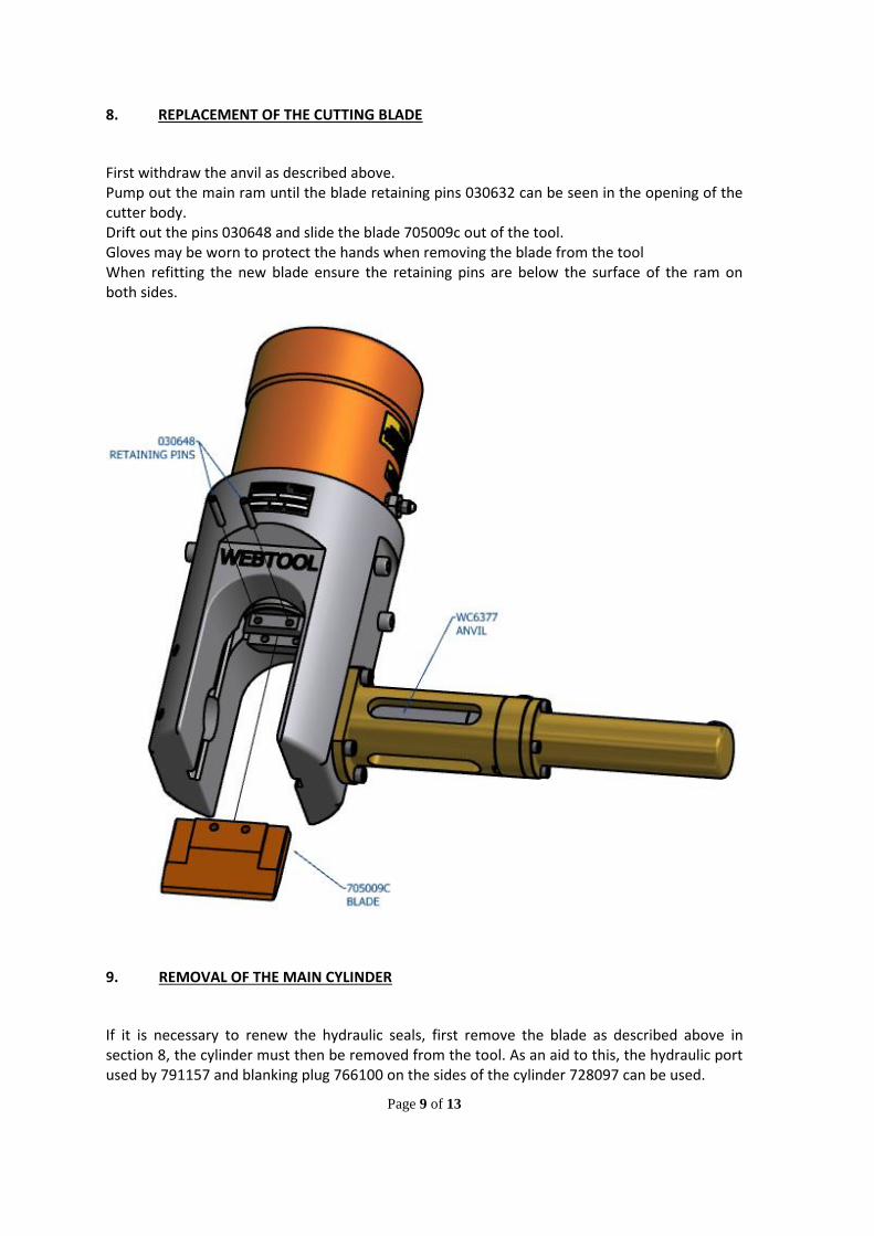
8. REPLACEMENT OF THE CUTTING BLADE
First withdraw the anvil as described above. Pump out the main ram until the blade retaining pins 030632 can be seen in the opening of the cutter body. Drift out the pins 030648 and slide the blade 705009c out of the tool. Gloves may be worn to protect the hands when removing the blade from the tool When refitting the new blade ensure the retaining pins are below the surface of the ram on both sides.
9. REMOVAL OF THE MAIN CYLINDER
If it is necessary to renew the hydraulic seals, first remove the blade as described above in section 8, the cylinder must then be removed from the tool. As an aid to this, the hydraulic port used by 791157 and blanking plug 766100 on the sides of the cylinder 728097 can be used.

Page 10 of 13
The hydraulic fittings should first be removed, then a threaded bar is to be screwed into each port, apply a torque and not a bending moment when screwing the cylinder. The thread in the ports is ¼” BSP. These can be used to loosen or re-tighten the cylinder. The cylinder is a pressure vessel and should not be drilled, machined, mutilated or damaged in any way for mounting purposes or to assist in its removal for servicing, any warranty could be invalidated by such actions. Do not use Stilsons to remove the cylinder as damage will occur.

Page 11 of 13
Also available as an optional extra Webtool Hydraulic Intensifier – HP690A (available in a range on intensification ratios)
For further information contact the manufacturer (Allspeeds Ltd) or an authorised distributor.
WCS75HDZ – Part List 980482
Part No. Description Qty.
710 302 Cutter body 1
728 097 Cylinder 1
764 088 Ram 1
774 026 Bearing ring 1
705 009c Blade 1
766 100 Blanking plug 1
WC6377 Anvil 1
030 648 Blade retaining pin 2
728 067 Anvil cylinder 1
749 042 Anvil housing 1
764 105 Anvil piston 1
749 046 Anvil seal housing 1
31-75-0825 Socket cap screws M8 4
31-63-1025 Socket cap screw M10 4
035 118 Socket cap screw M6 4
752 342 Webtool nameplate 1
766 047 Plastic plug 2
791 157 Coupling , 7/16” JIC No.4 – ¼” BSP 2
752 573 Pressure warning label 1
752 571 Port pressure label – cutting 1
752 574 Port pressure label – return 1

Page 12 of 13
Hydraulic Anvil Seal Kit 995122
Part No. Description Qty
025 801 Piston seal 1
025 802 Rod seal 1
025 569 Ram wiper 1
025 311 Seal O ring 1
Cutter Seal Kit 995119
Part No. Description Qty
025 570 Ram wiper 1
025 788 O seal 1
025 789 Anti extrusion ring 1
025 799 Piston seal 1
025 804 Ram seal 1
32-07-0035 Bonded seal 3
Hydraulic Anvil Kit 982117
Part No. Description Qty
728 067 Anvil cylinder 1
749 042 Anvil housing 1
764 105 Piston 1
WC6377 Anvil 1
749 046 Anvil seal housing 1
035 118 Socket cap screw M6 4
025 311 O ring seal 1
025 569 Rod wiper 1
025 801 Piston seal 1
025 802 Rod seal 1
31-75-0830 Socket cap screw M8 4
766 047 Plastic plug 2

Page 13 of 13
CUTTING EDGE TECHNOLOGY
Webtool specialises in engineering powerful hydraulic tools for
cutting and gripping rope, cable and umbilicals.
Models designed for use in subsea environments by ROV’s, and
surface applications in hostile environments.
Wire rope cutters (WCS and WCOS) – capable of cutting steel wire rope
up to 75mm diameter
Wire Rope Cutters (RCV) – capable of cutting steel wire rope up to
190mm diameter
Cable Cutters (HCV) – capable of cutting cable, umbilical and armoured
flexible pipe lines up to 330mm diameter
Softline Cutters (SL) – capable of cutting fibre ropes in various sizes
Wire Rope / Cable Grippers
Wire Rope Clamps
Automatic Shackles
Application specific solutions
Our in house design and manufacturing capability means we can
quickly and efficiently develop a solution to suit your particular
application. Contact our engineering department to discuss how we
can help.
Allspeeds Ltd, Royal Works, Atlas Street, Clayton-Le-Moors,
Accrington, Lancashire, BB5 5LW, England
T: +44 (0)1254 615100 F: +44 (0)1254 615199
E: [email protected] W: www.allspeeds.co.uk