wc bo0175255 001 - wacker neusonproducts.wackerneuson.com/manuals/operators/0175255en_001.pdf ·...
TRANSCRIPT
Mobile Generator
G 22
OPERATOR’S MANUAL
0175255en 001
0608
0 1 7 5 2 5 5 E N

G 22 Foreword
ForewordMachines covered by this manualMachine Documentation
Keep a copy of the Operator’s Manual with the machine at all times. Use the separate Parts Book supplied with the machine to order replacement parts. If you are missing any of these documents, please contact Wacker Neuson Corporation to order a replacement or visit www.wackerneuson.com. When ordering parts or requesting service information, be prepared to provide the machine model number, item number, revision number, and serial number.
Expectations for information in this manual
This manual provides information and procedures to safely operate and maintain the above Wacker Neuson model(s). For your own safety and to reduce the risk of injury, carefully read, understand, and observe all instructions described in this manual. Wacker Neuson Corporation expressly reserves the right to make technical modifications, even without notice, which improve the performance or safety standards of its machines.The information contained in this manual is based on machines manufactured up until the time of publication. Wacker Neuson Corporation reserves the right to change any portion of this information without notice.
Copyright notice
All rights, especially copying and distribution rights, are reserved.Copyright 2008 by Wacker Neuson Corporation.This publication may be reproduced through photocopying by the original purchaser of the machine. Any other type of reproduction is prohibited without express written permission from Wacker Neuson Corporation.Any type of reproduction or distribution not authorized by Wacker Neuson Corporation represents an infringement of valid copyrights, and violators will be prosecuted.
Trademarks All trademarks referenced in this manual are the property of their respective owners.
Machine Item NumberG 22 0620543
wc_tx000883gb.fm 3

Foreword G 22
wc_tx000883gb.fm 4
G 22 Table of Contents
Foreword 31 Safety Information 7
1.1 Signal Words Found in this Manual ...................................................... 71.2 Safety Instructions for Operating the Machine ..................................... 81.3 Safety Instructions for Towing ............................................................ 101.4 Safety Instructions for Servicing the Machine .................................... 111.5 Label Locations .................................................................................. 141.6 Label Meanings .................................................................................. 15
2 Transporting, Lifting, and Storing 16
2.1 Transporting ....................................................................................... 162.2 Storing ................................................................................................ 162.3 Lifting .................................................................................................. 17
3 Operating the Machine 19
3.1 Application .......................................................................................... 193.2 Control/Component Locations ............................................................ 203.3 Control/Component Descriptions ....................................................... 213.4 Control Panel/Microprocessor ............................................................ 223.5 Control Panel/Microprocessor Functions ........................................... 223.6 Main Control Switch Positions/Functions ........................................... 243.7 Preliminary Checklist .......................................................................... 263.8 Starting the Generator ........................................................................ 273.9 Stopping the Generator ...................................................................... 283.10 Connecting Loads to the Terminal Lugs ............................................. 293.11 Operating the Generator .................................................................... 303.12 Microprocessor Display Screens ........................................................ 31
4 Maintenance 34
4.1 Periodic Maintenance Schedule ......................................................... 344.2 Checking the Engine Oil ..................................................................... 35
wc_bo0175255_001TOC.fm 5
Table of Contents G 22
4.3 Changing the Engine Oil .....................................................................364.4 Changing Oil Filter ...............................................................................374.5 Changing the Fuel Filter ......................................................................384.6 Air Cleaner Discharge Valve ...............................................................394.7 Cleaning/Changing Air Filter Cartridges ..............................................404.8 Checking the Alternator V-Belt ............................................................414.9 Lubricating the Trailer ..........................................................................424.10 Cleaning the Engine ............................................................................434.11 Changing/Tensioning Alternator V-Belt ...............................................444.12 Checking/Adjusting Valve Clearances ................................................454.13 Checking Battery Electrolyte ...............................................................475 Schematics 48
5.1 Power Wiring .......................................................................................485.2 Power Wiring Components ..................................................................495.3 Engine Wiring ......................................................................................505.4 Engine Wiring Components .................................................................515.5 Socket Wiring ......................................................................................525.6 Socket Wirng Components ..................................................................535.7 Control Wiring ......................................................................................545.8 Control Wiring Components ................................................................55
6 Basic Troubleshooting 56
7 Technical Data 57
7.1 Machine ...............................................................................................577.2 Engine .................................................................................................587.3 Dimensions ..........................................................................................597.4 Sound Specification .............................................................................60
wc_bo0175255_001TOC.fm 6
50Hz Mobile Generators Safety Information
1 Safety Information1.1 Signal Words Found in this Manual
NOTICE: Used without the safety alert symbol, NOTICE indicates a situation which, if not avoided, could result in property damage.
Note: Contains additional information important to a procedure.
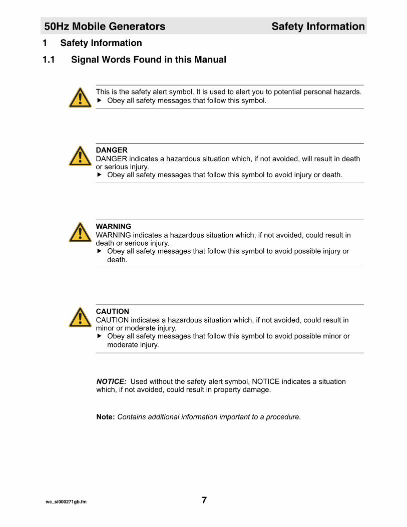
This is the safety alert symbol. It is used to alert you to potential personal hazards.Obey all safety messages that follow this symbol.
DANGERDANGER indicates a hazardous situation which, if not avoided, will result in death or serious injury.
Obey all safety messages that follow this symbol to avoid injury or death.
WARNINGWARNING indicates a hazardous situation which, if not avoided, could result in death or serious injury.
Obey all safety messages that follow this symbol to avoid possible injury or death.
CAUTIONCAUTION indicates a hazardous situation which, if not avoided, could result in minor or moderate injury.
Obey all safety messages that follow this symbol to avoid possible minor or moderate injury.
wc_si000271gb.fm 7

Safety Information 50Hz Mobile Generators
1.2 Safety Instructions for Operating the MachineSafety devices, controls, and attachments
Only operate the machine when:All safety devices and guards are in place and in working order.All controls operate correctly.The machine is set up correctly according to the instructions in the Operator’s Manual.The machine is clean.The machine’s labels are legible.
To ensure safe operation of the machine:Do not operate the machine if any safety devices or guards are missing or inop-erative.Do not modify or defeat the safety devices. Do not use accessories or attachments that are not recommended by Wacker Neuson Corporation.
Operator training
Before operating the machine:Read and understand the operating instructions contained in all manuals delivered with the machine.Familiarize yourself with the location and proper use of all controls and safety devices. Contact Wacker Neuson Corporation for additional training if necessary.
When operating this machine:Do not allow improperly trained people to operate the machine. People operating the machine must be familiar with the potential risks and hazards associated with it.
Safe operating practices
When operating this machine:Remain aware of the machine’s moving parts. Keep hands, feet, and loose clothing away from the machine’s moving parts.Wear protective clothing appropriate to the job site when operating the machine.Wear safety glasses when operating this machine.Wear hearing protection when operating this machine.
When operating this machine:Do not operate a machine in need of repair.
DANGERElectric shock hazard. Backfeed from the generator into the public power distribu-tion system can seriously injure or kill utility workers!
Connections to a building’s electrical system must be made by a qualified elec-trician and comply with all applicable laws and electrical codes.
wc_si000271gb.fm 8
50Hz Mobile Generators Safety Information
Work area Be aware of the work area. Keep unauthorized personnel, children, and pets away from the machine.Remain aware of changing positions and the movement of other equipment and personnel in the application area/job site.Keep the machine at least one meter (three feet) away from structures, build-ings, and other equipment during use.Keep the area immediately surrounding and underneath the machine clean, neat, and free of debris and combustible materials. Make sure that the area overhead is clear of debris that could fall onto or into the machine or exhaust compartment.Make sure the machine is on a firm, level surface and will not tip, roll, slide, or fall while operating.
Be aware of the application area.Never operate the machine indoors unless exhaust fumes can be adequately ventilated.Never operate the machine in areas that contain flammable objects, fuels, or products that produce flammable vapors.Never operate the machine if you or the machine are in water.
Electrical safety
To increase electrical safety while operating this machine, follow the procedures below.
Do not operate the generator, or tools attached to the generator, with wet hands.Do not use worn electrical cords. Make certain the machine is well-grounded and securely fastened to a good earthen ground per national and local regulations.Do not overload the generator. The total amperage of the tools and equipment attached to the generator must not exceed the load rating of the generator.
Storing the machine
Store the machine properly when it is not being used. The machine should be stored in a clean, dry location out of the reach of children.
wc_si000271gb.fm 9
Safety Information 50Hz Mobile Generators
1.3 Safety Instructions for TowingHitch and coupling
To reduce the possibility of an accident, perform the following before towing.Check that the hitch and coupling on the vehicle are rated equal to, or greater than, the trailer's “gross vehicle weight rating” (GVWR).Inspect the hitch and coupling for wear or damage. DO NOT tow the trailer using defective parts.Make sure the coupling is securely fastened to the vehicle.Connect the safety chains.Connect the breakaway cable safety hook to the bumper or rear of the vehicle. Do not attach it to the hitch.
Tires and wheels
To reduce the possibility of an accident, perform the following before towing.Check the condition, tread wear, and air pressure of the trailer tires. Replace worn tires. Check that the wheel lug nuts are tight and that none are missing.
Brakes and lights
To reduce the possibility of an accident, perform the following before towing.Test the brake linkage on the trailer and the brakes on the towing vehicle.Make sure directional and trailer lights are connected and working properly.
WARNINGTowing a trailer requires special care. To reduce the possibility of an accident:
Both the trailer and the vehicle must be in good working condition.The trailer and the vehicle must be securely fastened to each other.
wc_si000271gb.fm 10
50Hz Mobile Generators Safety Information
1.4 Safety Instructions for Servicing the MachineService training
Before servicing or maintaining the machine:Read and understand the instructions contained in all manuals delivered with the machine.Familiarize yourself with the location and proper use of all controls and safety devices. Only trained personnel shall troubleshoot or repair problems occurring with the machine.Contact Wacker Neuson Corporation for additional training if necessary.
When servicing or maintaining this machine:Do not allow improperly trained people to service or maintain the machine. Per-sonnel servicing or maintaining the machine must be familiar with the associ-ated potential risks and hazards.
Precautions Follow the precautions below when servicing or maintaining the machine.Read and understand the service procedures before performing any service to the machine.All adjustments and repairs must be completed before operation. Do not oper-ate the machine with a known problem or deficiency.
Safe servicing practices
When servicing and maintaining this machine:Be aware of the machine’s moving parts. Keep hands, feet, and loose clothing away from the machine’s moving parts.Wear protective clothing appropriate to the job.Wear safety glasses.Wear hearing protection if required.Re-install the safety devices and guards after repairs and maintenance.
Machine modifications
When servicing or maintaining the machine:Use only accessories/attachments recommended by Wacker Neuson Corpora-tion.
When servicing or maintaining the machine:Do not defeat the safety devices. Do not modify the machine without the express written approval of Wacker Neuson Corporation.
WARNINGA poorly maintained machine can be a personal injury hazard.
Follow the Periodic Maintenance schedule in this Operator’s Manual.Repair or replace any damaged or defective components immediately.
wc_si000271gb.fm 11
Safety Information 50Hz Mobile Generators
Replacing parts and labels
Replace worn or damaged components.Use only spare parts recommended by Wacker Neuson Corporation.Replace all missing and hard-to-read labels.When replacing electrical components, use components that are identical in rating and performance as the original components.
Before servicing
Complete the following procedures before servicing the machine.Turn off the machine.Open the circuit breakers (“OFF”).Disconnect the battery.Attach a “DO NOT START” sign to the control panel. Make sure that the remote start or transfer switch (if used) is also off and tagged.Let the engine cool.
Lifting and transporting
When lifting the machine:Make sure slings, chains, hooks, ramps, jacks and other types of lifting devices are attached securely and have enough weight-bearing capacity to lift or hold the machine safely. Be aware of the location of other people when lifting the machine.
To reduce the possibility of injury:Do not stand under the machine while it is being hoisted or moved.Do not get onto the machine while it is being hoisted or moved.
wc_si000271gb.fm 12

50Hz Mobile Generators Safety Information
Noteswc_si000271gb.fm 13
Safety Information 50Hz Mobile Generators
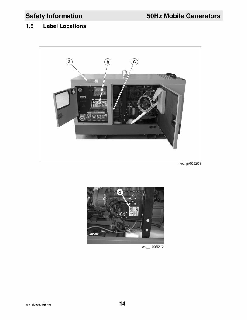
1.5 Label Locationsa b c
wc_gr005209
wc_si000271gb.fm 14
50Hz Mobile Generators Safety Information
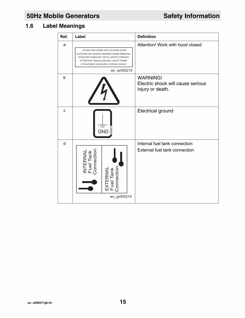
1.6 Label MeaningsRef. Label Definition
a Attention! Work with hood closed
b WARNING! Electric shock will cause serious injury or death.
c Electrical ground
d Internal fuel tank connectionExternal fuel tank connection
GND 88897
wc_si000271gb.fm 15
Transporting, Lifting, and Storing 50Hz Mobile Generators
2 Transporting, Lifting, and Storing2.1 TransportingWhen transporting the machine, only use transport vehicles with enough weight-bearing capacity for both the generator and the trailer. See section Technical Data.Secure the generator and the trailer to the transport vehicle.
2.2 StoringWhen storing the machine for more than 30 days:
Drain the fuel tank.Change the engine oil.Disconnect the battery.Clean the machine.Cover the machine.
wc_tx000895gb.fm 16
50Hz Mobile Generators Transporting, Lifting, and Storing
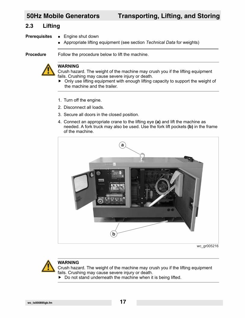
2.3 LiftingPrerequisites Engine shut downAppropriate lifting equipment (see section Technical Data for weights)
Procedure Follow the procedure below to lift the machine.
1. Turn off the engine.2. Disconnect all loads.3. Secure all doors in the closed position.4. Connect an appropriate crane to the lifting eye (a) and lift the machine as
needed. A fork truck may also be used. Use the fork lift pockets (b) in the frame of the machine.
WARNINGCrush hazard. The weight of the machine may crush you if the lifting equipment fails. Crushing may cause severe injury or death.
Only use lifting equipment with enough lifting capacity to support the weight of the machine and the trailer.
WARNINGCrush hazard. The weight of the machine may crush you if the lifting equipment fails. Crushing may cause severe injury or death.
Do not stand underneath the machine when it is being lifted.
wc_tx000895gb.fm 17
Transporting, Lifting, and Storing 50Hz Mobile Generators
Noteswc_tx000895gb.fm 18
50Hz Mobile Generators Operating the Machine
3 Operating the Machine3.1 Application
Generator application
This machine is a heavy-duty, compact, sound-attenuated generator designed to provide single and three-phase power for construction, commercial, and industrial applications where reliable power is needed..
Safety notices Do not exceed the power output of the generator. Damage to tools or generator will occur. Refer to Technical Data.When using the generator as a standby or substitute power supply, make sure the voltage and phase rotation of the line connections match those of the mains lines. Failure to match phase rotation and voltage may cause equipment con-nected to the generator to operate incorrectly! This could create unsafe operat-ing conditions.Do not exceed the rated current limit of any receptacle.
wc_tx000884gb.fm 19
Operating the Machine 50Hz Mobile Generators
3.2 Control/Component Locationsa b c d e f
gh
m
p
ijkl
wc_gr005210
wc_tx000884gb.fm 20

50Hz Mobile Generators Operating the Machine
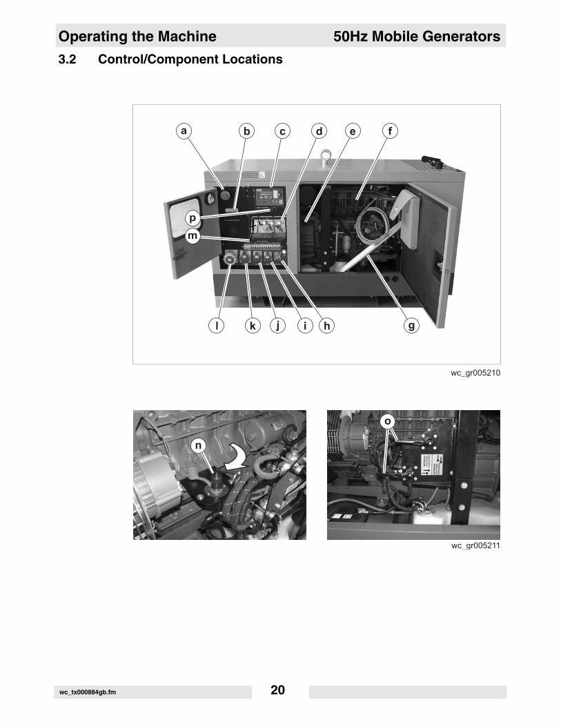
3.3 Control/Component DescriptionsRef. Description Ref. Descriptiona Emergency stop switch
Pressing this push button stops the generator immediately. When pressed, the LCD display reads: “ALARM EMERGENCY”. To release the emergency sta-tus, place the main control switch in the LOCK position, then turn and pull out the emergency stop switch.
i Socket220V, 16A, 1P +N CEE/IEC309
b Main circuit breakerThe main circuit breaker controls voltage to both the lugs and to the individual circuit breakers.
j Socket380V, 16A, 3P +N CEE/IEC309
c MicroprocessorThe microprocessor controls the operation of the generator.
k Socket380V, 32A, 3P +N CEE/IEC309
d 3-phase voltage lugsConnection point for 400V, 3Ø loads.
l Socket380V, 63A, 3P +N CEE/IEC309
e AlternatorMeccAlte alternator (generator)
m Individual circuit breaker panelEach socket has its own individ-ual circuit breaker.
f EngineDeutz
n Battery cut-off switchThis switch disconnects the bat-tery from the engine and the microprocessor.
g Grounding stakeThe grounding stake is used to connect the machine to earthen ground.
o External fuel tank connection point and control valves
h Socket250V, 16A, 1P + N Shuko
p Engine protection switchThis switch controls battery power to the engine and the microprocessor.
wc_tx000884gb.fm 21

Operating the Machine 50Hz Mobile Generators
3.4 Control Panel/Microprocessor3.5 Control Panel/Microprocessor Functions
CR
CGENTER
a
p
o
n
ijklm h g f
q
b c
d
e
r
Ref. Description Ref. Descriptiona LCD display
The microprocessor displays the various functions and alarms of the generator in this window.
j Charging system LEDThis LED illuminates when the charging system is active. This LED will flash when there is a problem with the charging sys-tem.
b Reset buttonPressing this button once silences the audible alarm. Pressing it again resets the microprocessor.
k Alternator LEDThis LED illuminates when the alternator is active. This LED will flash when there is a problem with the alternator.
wc_tx000884gb.fm 22
50Hz Mobile Generators Operating the Machine
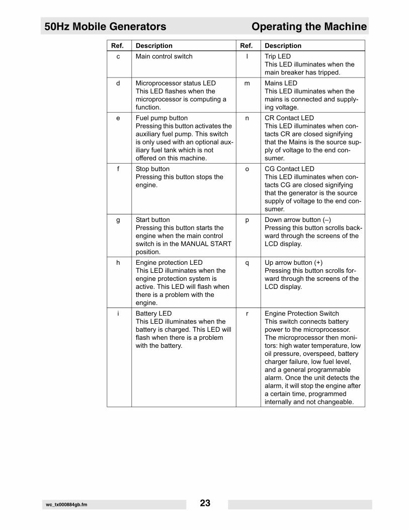
c Main control switch l Trip LEDThis LED illuminates when the main breaker has tripped.
d Microprocessor status LEDThis LED flashes when the microprocessor is computing a function.
m Mains LEDThis LED illuminates when the mains is connected and supply-ing voltage.
e Fuel pump buttonPressing this button activates the auxiliary fuel pump. This switch is only used with an optional aux-iliary fuel tank which is not offered on this machine.
n CR Contact LEDThis LED illuminates when con-tacts CR are closed signifying that the Mains is the source sup-ply of voltage to the end con-sumer.
f Stop buttonPressing this button stops the engine.
o CG Contact LED This LED illuminates when con-tacts CG are closed signifying that the generator is the source supply of voltage to the end con-sumer.
g Start buttonPressing this button starts the engine when the main control switch is in the MANUAL START position.
p Down arrow button (–)Pressing this button scrolls back-ward through the screens of the LCD display.
h Engine protection LEDThis LED illuminates when the engine protection system is active. This LED will flash when there is a problem with the engine.
q Up arrow button (+) Pressing this button scrolls for-ward through the screens of the LCD display.
i Battery LEDThis LED illuminates when the battery is charged. This LED will flash when there is a problem with the battery.
r Engine Protection SwitchThis switch connects battery power to the microprocessor. The microprocessor then moni-tors: high water temperature, low oil pressure, overspeed, battery charger failure, low fuel level, and a general programmable alarm. Once the unit detects the alarm, it will stop the engine after a certain time, programmed internally and not changeable.
Ref. Description Ref. Description
wc_tx000884gb.fm 23

Operating the Machine 50Hz Mobile Generators
3.6 Main Control Switch Positions/FunctionsPosition Description
AUTOMATIC TEST With the control switch in this position:The engine will start automatically.The microprocessor will test the function of the generator systems. The results of the tests are displayed on LCD screens. Scroll through the LCD screens by using the arrow keys.The tests do not require the mains supply to be disconnected from the end consumer.
AUTOMATIC RUNNING With the control switch in this position:The engine will start automatically if the machine is not connected to a mains supply.The microprocessor is programmed to route power (CR closed) from the mains supply to the end consumer (utility) unless a problem with the mains supply is detected. At such a time, the microprocessor starts the generator and routes power (CG closed, CR open) from the generator to the end consumer. At the point where the mains supply is again stable, the microprocessor closes contacts CR and opens contacts CG. The engine will run for approximately 1 minute to allow it to cool.
LOCKED ENGINE With the control switch in this position:The engine will not start.Power to all generator systems is discon-nected.The mains supply is the sole source of power to the end consumer if connected.
wc_tx000884gb.fm 24
50Hz Mobile Generators Operating the Machine
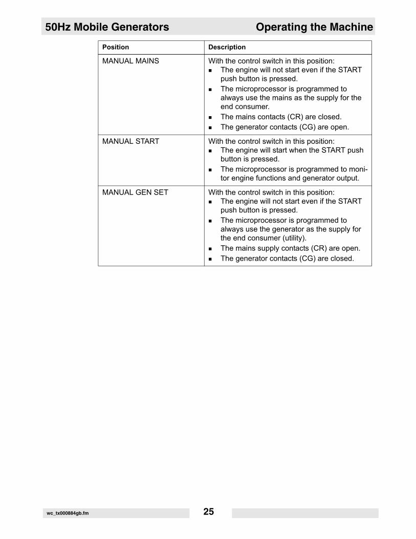
MANUAL MAINS With the control switch in this position:The engine will not start even if the START push button is pressed.The microprocessor is programmed to always use the mains as the supply for the end consumer.The mains contacts (CR) are closed.The generator contacts (CG) are open.
MANUAL START With the control switch in this position:The engine will start when the START push button is pressed.The microprocessor is programmed to moni-tor engine functions and generator output.
MANUAL GEN SET With the control switch in this position:The engine will not start even if the START push button is pressed.The microprocessor is programmed to always use the generator as the supply for the end consumer (utility).The mains supply contacts (CR) are open.The generator contacts (CG) are closed.
Position Description
wc_tx000884gb.fm 25
Operating the Machine 50Hz Mobile Generators
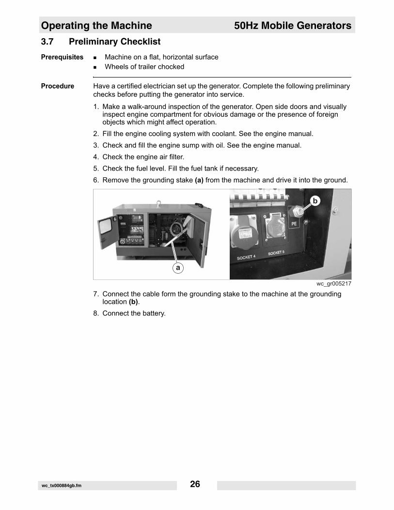
3.7 Preliminary ChecklistPrerequisites Machine on a flat, horizontal surfaceWheels of trailer chocked
Procedure Have a certified electrician set up the generator. Complete the following preliminary checks before putting the generator into service.
1. Make a walk-around inspection of the generator. Open side doors and visually inspect engine compartment for obvious damage or the presence of foreign objects which might affect operation.
2. Fill the engine cooling system with coolant. See the engine manual.3. Check and fill the engine sump with oil. See the engine manual.4. Check the engine air filter. 5. Check the fuel level. Fill the fuel tank if necessary.6. Remove the grounding stake (a) from the machine and drive it into the ground.
7. Connect the cable form the grounding stake to the machine at the grounding location (b).
8. Connect the battery.
wc_tx000884gb.fm 26
50Hz Mobile Generators Operating the Machine
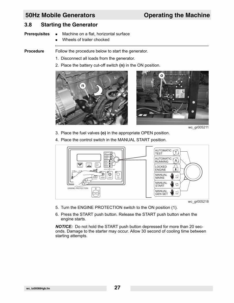
3.8 Starting the GeneratorPrerequisites Machine on a flat, horizontal surfaceWheels of trailer chocked
Procedure Follow the procedure below to start the generator.
1. Disconnect all loads from the generator.2. Place the battery cut-off switch (n) in the ON position.
3. Place the fuel valves (o) in the appropriate OPEN position.4. Place the control switch in the MANUAL START position.
5. Turn the ENGINE PROTECTION switch to the ON position (1).6. Press the START push button. Release the START push button when the
engine starts.
NOTICE: Do not hold the START push button depressed for more than 20 sec-onds. Damage to the starter may occur. Allow 30 second of cooling time between starting attempts.
CR
CGENTER
wc_tx000884gb.fm 27
Operating the Machine 50Hz Mobile Generators
3.9 Stopping the GeneratorPrerequisites All tools disconnected from generatorWheels of trailer chocked
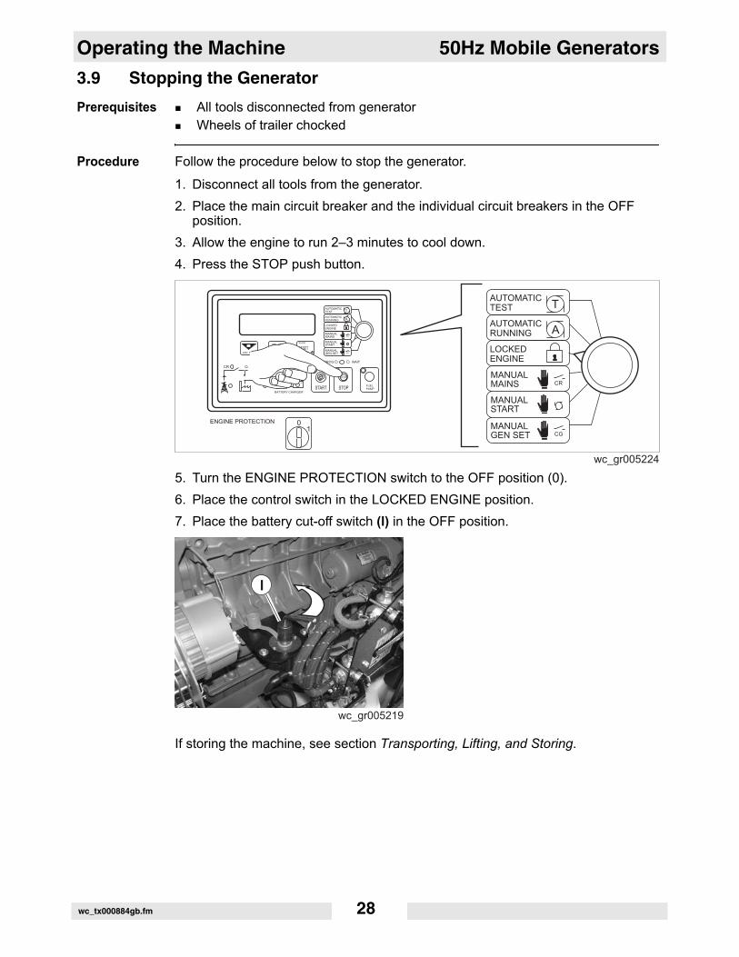
Procedure Follow the procedure below to stop the generator.
1. Disconnect all tools from the generator.2. Place the main circuit breaker and the individual circuit breakers in the OFF
position.3. Allow the engine to run 2–3 minutes to cool down.4. Press the STOP push button.
5. Turn the ENGINE PROTECTION switch to the OFF position (0).6. Place the control switch in the LOCKED ENGINE position.7. Place the battery cut-off switch (l) in the OFF position.
If storing the machine, see section Transporting, Lifting, and Storing.
CR
CGENTER
wc_tx000884gb.fm 28
50Hz Mobile Generators Operating the Machine
3.10 Connecting Loads to the Terminal LugsPrerequisites Engine shut downWheels of trailer chockedThe appropriate qualifications and training mandated by the country where the generator will be installed. If you do not have the appropriate qualifications, do not continue with this procedure.
Procedure Follow the procedure below when connecting to the terminal lugs.
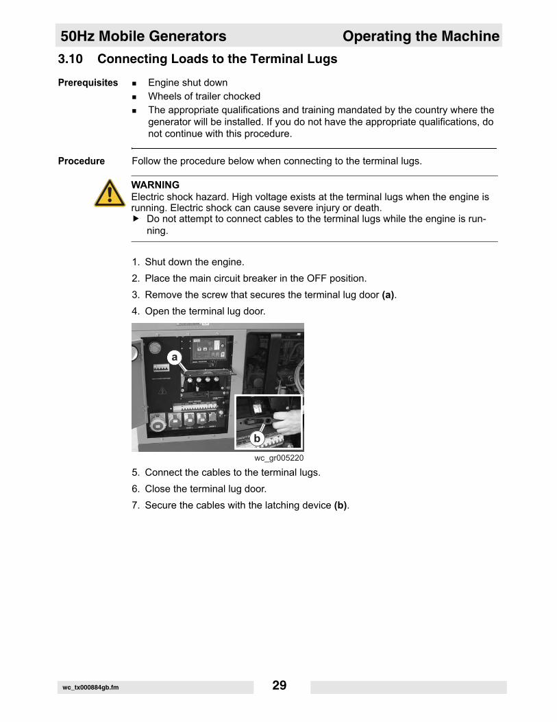
1. Shut down the engine.2. Place the main circuit breaker in the OFF position.3. Remove the screw that secures the terminal lug door (a).4. Open the terminal lug door.
5. Connect the cables to the terminal lugs.6. Close the terminal lug door.7. Secure the cables with the latching device (b).
WARNINGElectric shock hazard. High voltage exists at the terminal lugs when the engine is running. Electric shock can cause severe injury or death.
Do not attempt to connect cables to the terminal lugs while the engine is run-ning.
wc_tx000884gb.fm 29
Operating the Machine 50Hz Mobile Generators
3.11 Operating the GeneratorPrerequisites All preliminary checks madeWheels of trailer chocked
Procedure Follow the procedure below when operating the generator.
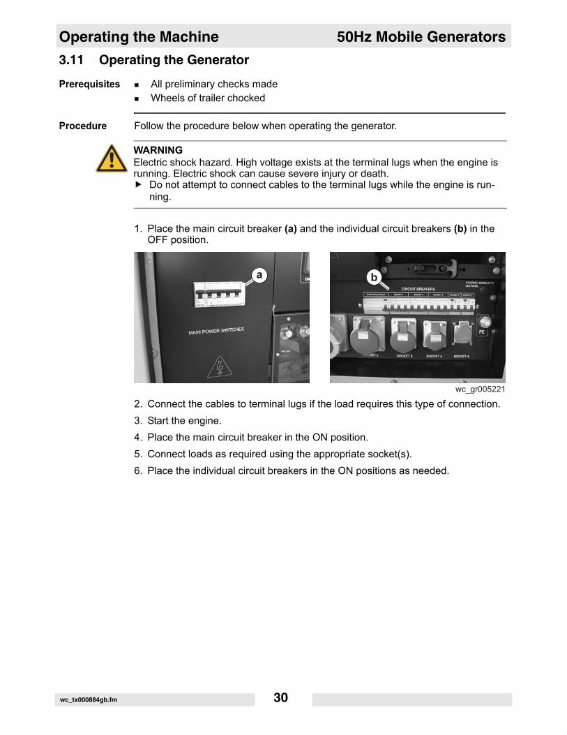
1. Place the main circuit breaker (a) and the individual circuit breakers (b) in the OFF position.
2. Connect the cables to terminal lugs if the load requires this type of connection.3. Start the engine.4. Place the main circuit breaker in the ON position.5. Connect loads as required using the appropriate socket(s).6. Place the individual circuit breakers in the ON positions as needed.
WARNINGElectric shock hazard. High voltage exists at the terminal lugs when the engine is running. Electric shock can cause severe injury or death.
Do not attempt to connect cables to the terminal lugs while the engine is run-ning.
wc_tx000884gb.fm 30
50Hz Mobile Generators Operating the Machine
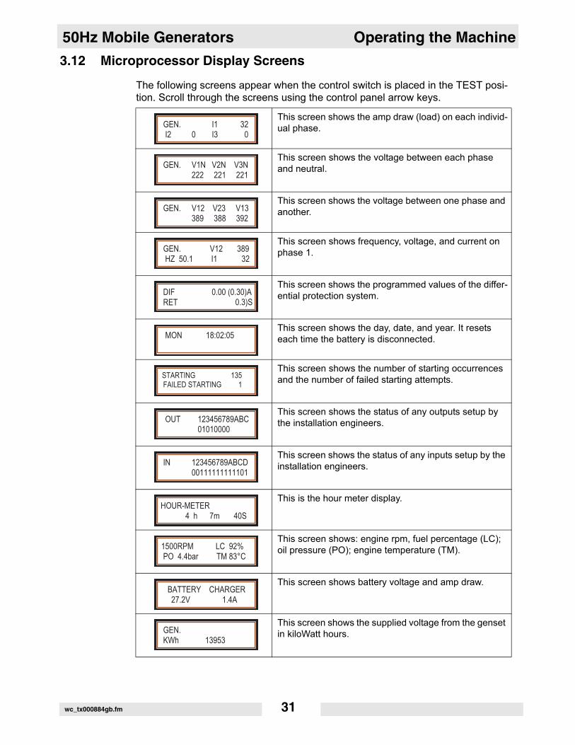
3.12 Microprocessor Display ScreensThe following screens appear when the control switch is placed in the TEST posi-tion. Scroll through the screens using the control panel arrow keys.
This screen shows the amp draw (load) on each individ-ual phase.
This screen shows the voltage between each phase and neutral.
This screen shows the voltage between one phase and another.
This screen shows frequency, voltage, and current on phase 1.
This screen shows the programmed values of the differ-ential protection system.
This screen shows the day, date, and year. It resets each time the battery is disconnected.
This screen shows the number of starting occurrences and the number of failed starting attempts.
This screen shows the status of any outputs setup by the installation engineers.
This screen shows the status of any inputs setup by the installation engineers.
This is the hour meter display.
This screen shows: engine rpm, fuel percentage (LC); oil pressure (PO); engine temperature (TM).
This screen shows battery voltage and amp draw.
This screen shows the supplied voltage from the genset in kiloWatt hours.
GEN. I1 32 I2 0 I3 0
GEN. V1N V2N V3N 222 221 221
GEN. V12 V23 V13 389 388 392
GEN. V12 389 HZ 50.1 I1 32
DIFRET
0.00 (0.30)A 0.3)S
MON 18:02:05
STARTING 135 FAILED STARTING 1
OUT 123456789ABC 01010000
IN 123456789ABCD 00111111111101
HOUR-METER 4 h 7m 40S
1500RPM LC 92% PO 4.4bar TM 83°C
BATTERY CHARGER 27.2V 1.4A
GEN. KWh 13953
wc_tx000884gb.fm 31
Operating the Machine 50Hz Mobile Generators
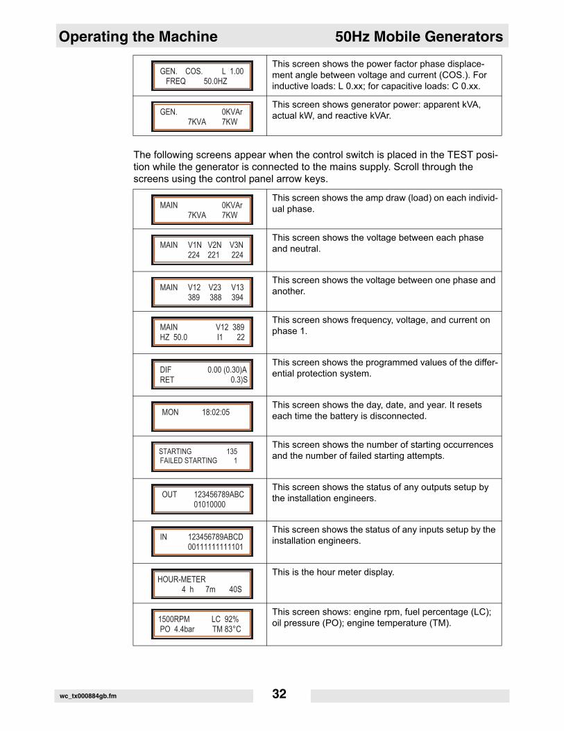
The following screens appear when the control switch is placed in the TEST posi-tion while the generator is connected to the mains supply. Scroll through the screens using the control panel arrow keys.
This screen shows the power factor phase displace-ment angle between voltage and current (COS.). For inductive loads: L 0.xx; for capacitive loads: C 0.xx.
This screen shows generator power: apparent kVA, actual kW, and reactive kVAr.
GEN. COS. L 1.00 FREQ 50.0HZ
GEN. 0KVAr 7KVA 7KW
This screen shows the amp draw (load) on each individ-ual phase.
This screen shows the voltage between each phase and neutral.
This screen shows the voltage between one phase and another.
This screen shows frequency, voltage, and current on phase 1.
This screen shows the programmed values of the differ-ential protection system.
This screen shows the day, date, and year. It resets each time the battery is disconnected.
This screen shows the number of starting occurrences and the number of failed starting attempts.
This screen shows the status of any outputs setup by the installation engineers.
This screen shows the status of any inputs setup by the installation engineers.
This is the hour meter display.
This screen shows: engine rpm, fuel percentage (LC); oil pressure (PO); engine temperature (TM).
MAIN 0KVAr 7KVA 7KW
MAIN V1N V2N V3N 224 221 224
MAIN V12 V23 V13 389 388 394
MAIN V12 389HZ 50.0 I1 22
DIFRET
0.00 (0.30)A 0.3)S
MON 18:02:05
STARTING 135 FAILED STARTING 1
OUT 123456789ABC 01010000
IN 123456789ABCD 00111111111101
HOUR-METER 4 h 7m 40S
1500RPM LC 92% PO 4.4bar TM 83°C
wc_tx000884gb.fm 32
50Hz Mobile Generators Operating the Machine
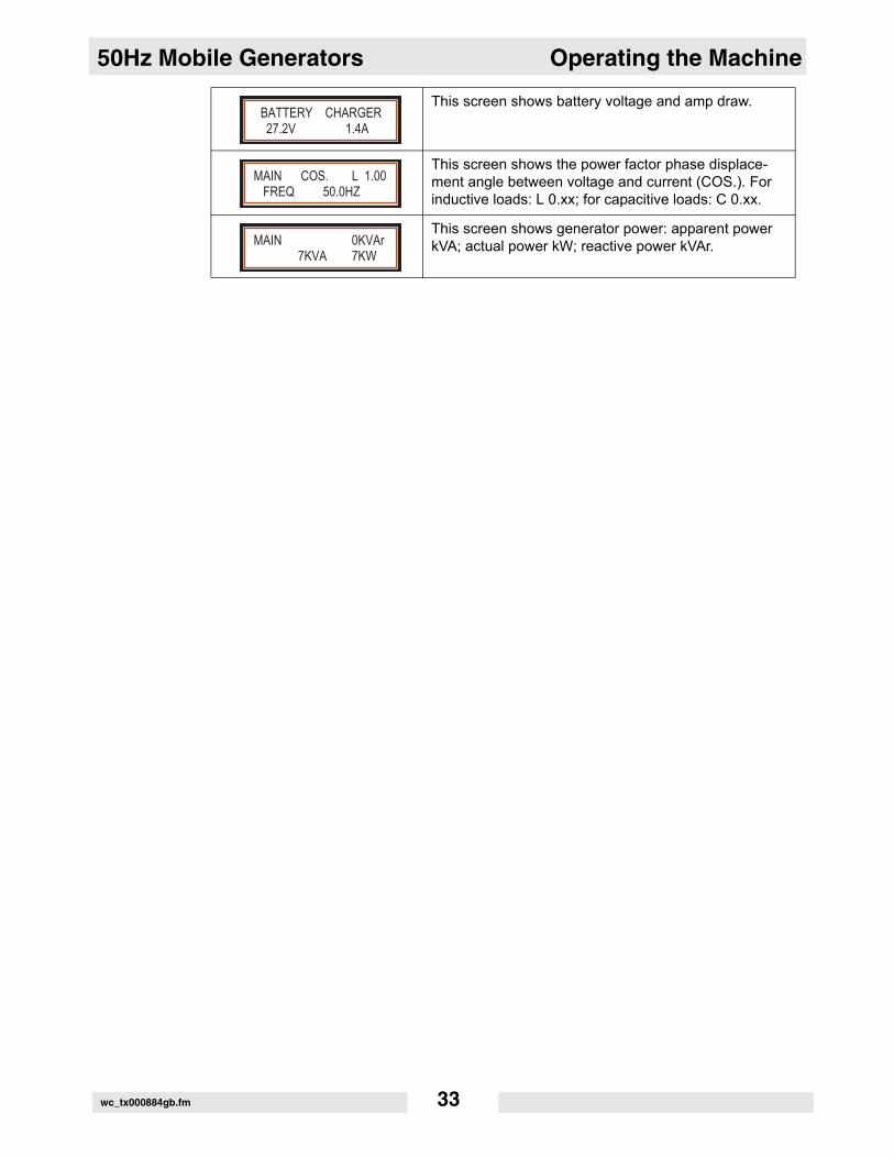
This screen shows battery voltage and amp draw.
This screen shows the power factor phase displace-ment angle between voltage and current (COS.). For inductive loads: L 0.xx; for capacitive loads: C 0.xx.
This screen shows generator power: apparent power kVA; actual power kW; reactive power kVAr.
BATTERY CHARGER 27.2V 1.4A
MAIN COS. L 1.00 FREQ 50.0HZ
MAIN 0KVAr 7KVA 7KW
wc_tx000884gb.fm 33
Maintenance 50Hz Mobile Generators
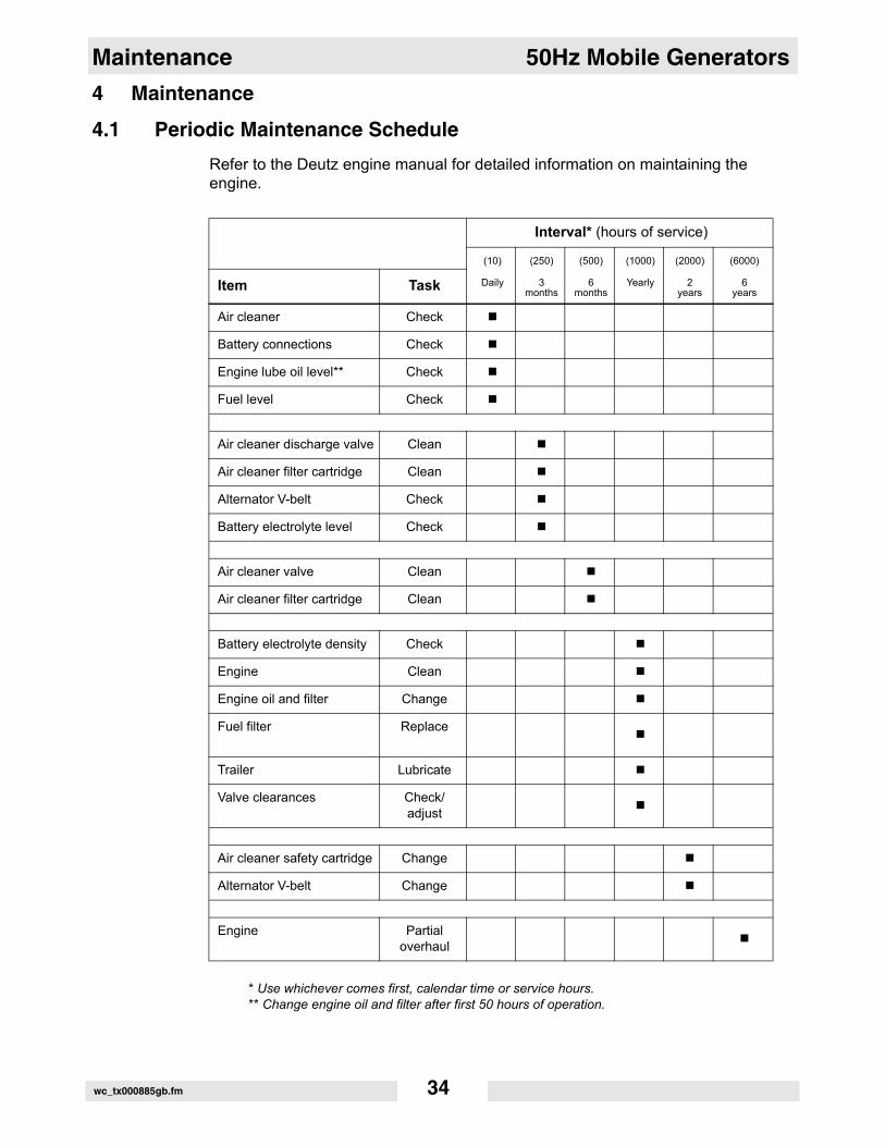
4 Maintenance4.1 Periodic Maintenance ScheduleRefer to the Deutz engine manual for detailed information on maintaining the engine.
* Use whichever comes first, calendar time or service hours.** Change engine oil and filter after first 50 hours of operation.
Interval* (hours of service)
(10) (250) (500) (1000) (2000) (6000)
Item Task Daily 3 months
6 months
Yearly 2 years
6 years
Air cleaner Check
Battery connections Check
Engine lube oil level** Check
Fuel level Check
Air cleaner discharge valve Clean
Air cleaner filter cartridge Clean
Alternator V-belt Check
Battery electrolyte level Check
Air cleaner valve Clean
Air cleaner filter cartridge Clean
Battery electrolyte density Check
Engine Clean
Engine oil and filter Change
Fuel filter Replace
Trailer Lubricate
Valve clearances Check/adjust
Air cleaner safety cartridge Change
Alternator V-belt Change
Engine Partial overhaul
wc_tx000885gb.fm 34
50Hz Mobile Generators Maintenance
4.2 Checking the Engine OilPrerequisites Machine on a level surfaceEngine off
When Every 10 hours of service or daily
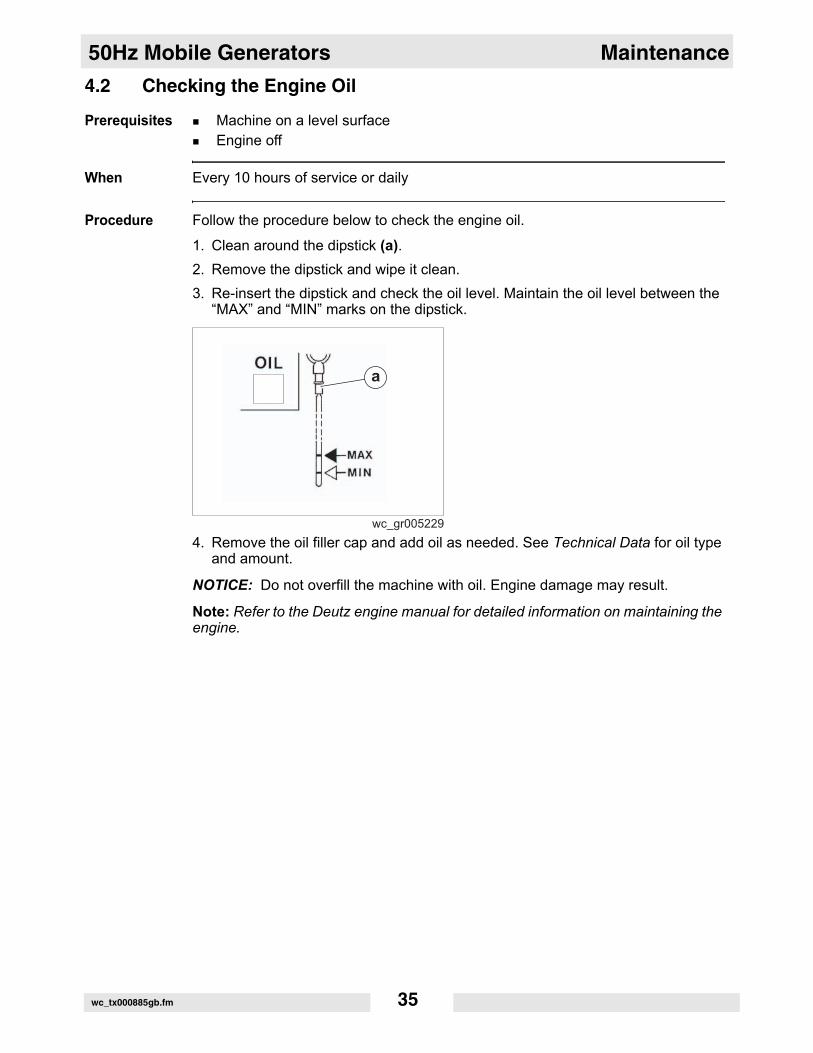
Procedure Follow the procedure below to check the engine oil.
1. Clean around the dipstick (a).2. Remove the dipstick and wipe it clean.3. Re-insert the dipstick and check the oil level. Maintain the oil level between the
“MAX” and “MIN” marks on the dipstick.
4. Remove the oil filler cap and add oil as needed. See Technical Data for oil type and amount.
NOTICE: Do not overfill the machine with oil. Engine damage may result.
Note: Refer to the Deutz engine manual for detailed information on maintaining the engine.
wc_tx000885gb.fm 35
Maintenance 50Hz Mobile Generators
4.3 Changing the Engine OilPrerequisites Machine on a level surfaceEngine offEngine oil warm—approximately 80°C (176°F)Oil trayDrain plug seal ring
When Every 1000 hours of service or yearly
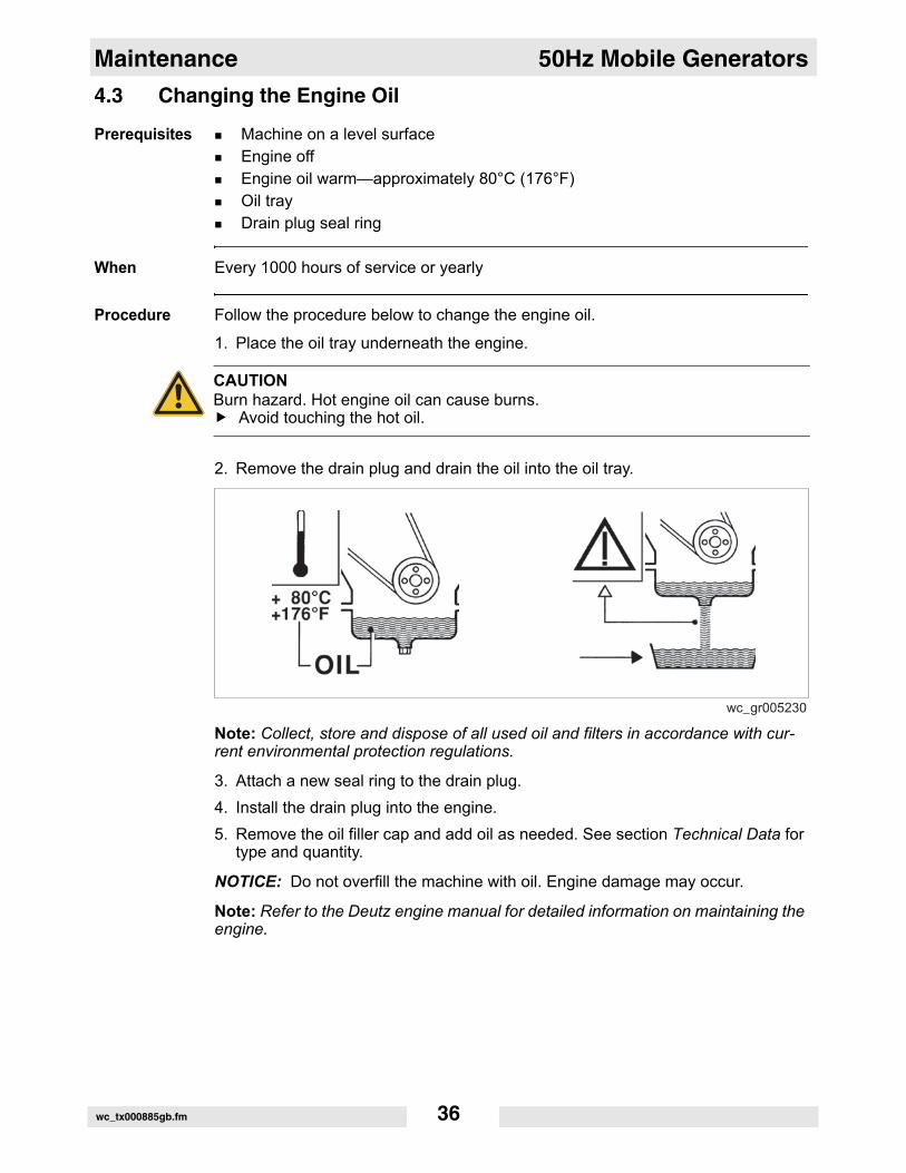
Procedure Follow the procedure below to change the engine oil.
1. Place the oil tray underneath the engine.
2. Remove the drain plug and drain the oil into the oil tray.
Note: Collect, store and dispose of all used oil and filters in accordance with cur-rent environmental protection regulations.
3. Attach a new seal ring to the drain plug.4. Install the drain plug into the engine.5. Remove the oil filler cap and add oil as needed. See section Technical Data for
type and quantity.
NOTICE: Do not overfill the machine with oil. Engine damage may occur.
Note: Refer to the Deutz engine manual for detailed information on maintaining the engine.
CAUTIONBurn hazard. Hot engine oil can cause burns.
Avoid touching the hot oil.
wc_gr005230
wc_tx000885gb.fm 36
50Hz Mobile Generators Maintenance
4.4 Changing Oil FilterPrerequisites Machine on a level surfaceEngine offEngine oil warm—approximately 80°C (176°F)New oil filter
When Every 1000 hours of service or yearly
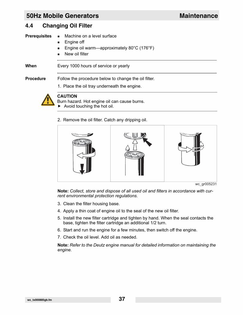
Procedure Follow the procedure below to change the oil filter.
1. Place the oil tray underneath the engine.
2. Remove the oil filter. Catch any dripping oil.
Note: Collect, store and dispose of all used oil and filters in accordance with cur-rent environmental protection regulations.
3. Clean the filter housing base.4. Apply a thin coat of engine oil to the seal of the new oil filter.5. Install the new filter cartridge and tighten by hand. When the seal contacts the
base, tighten the filter cartridge an additional 1/2 turn.6. Start and run the engine for a few minutes, then switch off the engine.7. Check the oil level. Add oil as needed.
Note: Refer to the Deutz engine manual for detailed information on maintaining the engine.
CAUTIONBurn hazard. Hot engine oil can cause burns.
Avoid touching the hot oil.
wc_tx000885gb.fm 37
Maintenance 50Hz Mobile Generators
4.5 Changing the Fuel FilterPrerequisites Engine offNew fuel filter
When Every 1000 hours of service or yearly
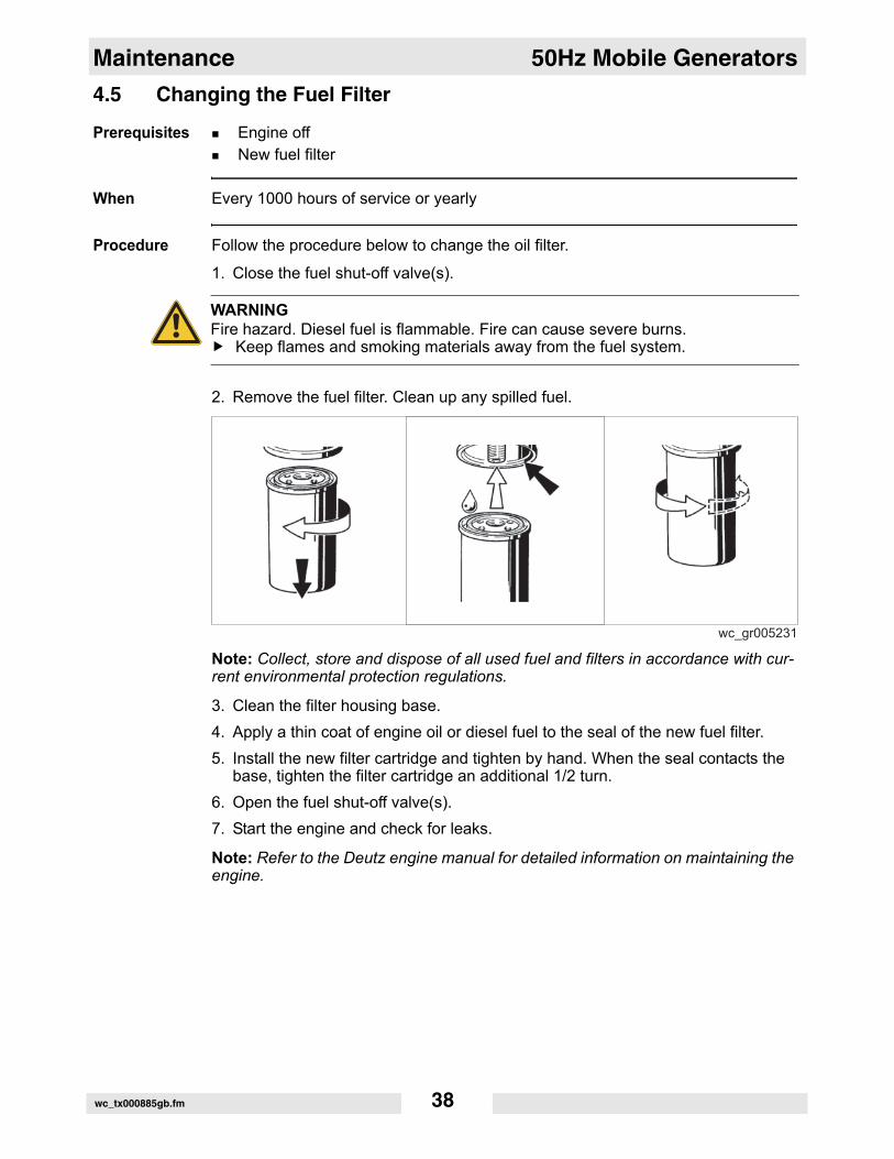
Procedure Follow the procedure below to change the oil filter.
1. Close the fuel shut-off valve(s).
2. Remove the fuel filter. Clean up any spilled fuel.
Note: Collect, store and dispose of all used fuel and filters in accordance with cur-rent environmental protection regulations.
3. Clean the filter housing base.4. Apply a thin coat of engine oil or diesel fuel to the seal of the new fuel filter.5. Install the new filter cartridge and tighten by hand. When the seal contacts the
base, tighten the filter cartridge an additional 1/2 turn.6. Open the fuel shut-off valve(s).7. Start the engine and check for leaks.
Note: Refer to the Deutz engine manual for detailed information on maintaining the engine.
WARNINGFire hazard. Diesel fuel is flammable. Fire can cause severe burns.
Keep flames and smoking materials away from the fuel system.
wc_tx000885gb.fm 38
50Hz Mobile Generators Maintenance
4.6 Air Cleaner Discharge ValvePrerequisites Engine offMachine cool
When Every 250 hours of service or every 3 months
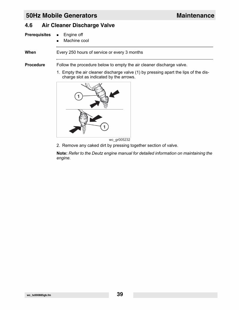
Procedure Follow the procedure below to empty the air cleaner discharge valve.
1. Empty the air cleaner discharge valve (1) by pressing apart the lips of the dis-charge slot as indicated by the arrows.
2. Remove any caked dirt by pressing together section of valve.
Note: Refer to the Deutz engine manual for detailed information on maintaining the engine.
wc_tx000885gb.fm 39
Maintenance 50Hz Mobile Generators
4.7 Cleaning/Changing Air Filter CartridgesPrerequisites Engine offSource of compressed air
When Every 500 hours of service or every 6 months (safety cartridge: 2 years)
Procedure Follow the procedure below to clean/change the air filter cartridges.
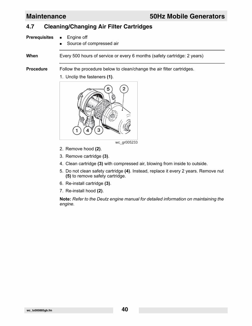
1. Unclip the fasteners (1).
2. Remove hood (2).3. Remove cartridge (3).4. Clean cartridge (3) with compressed air, blowing from inside to outside.5. Do not clean safety cartridge (4). Instead, replace it every 2 years. Remove nut
(5) to remove safety cartridge.6. Re-install cartridge (3).7. Re-install hood (2).
Note: Refer to the Deutz engine manual for detailed information on maintaining the engine.
wc_tx000885gb.fm 40
50Hz Mobile Generators Maintenance
4.8 Checking the Alternator V-BeltPrerequisites Engine offTension gauge
When Every 250 hours of service or every 3 months
Procedure Follow the procedure below to check the alternator V-belt.
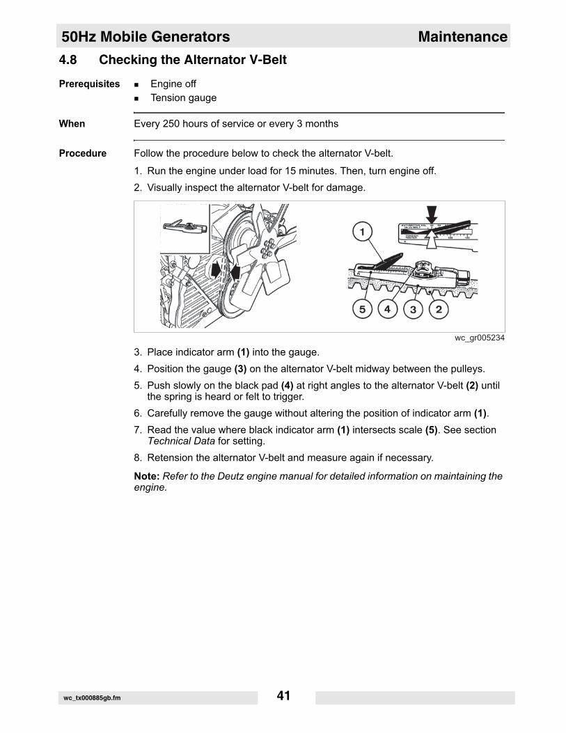
1. Run the engine under load for 15 minutes. Then, turn engine off.2. Visually inspect the alternator V-belt for damage.
3. Place indicator arm (1) into the gauge.4. Position the gauge (3) on the alternator V-belt midway between the pulleys.5. Push slowly on the black pad (4) at right angles to the alternator V-belt (2) until
the spring is heard or felt to trigger.6. Carefully remove the gauge without altering the position of indicator arm (1).7. Read the value where black indicator arm (1) intersects scale (5). See section
Technical Data for setting.8. Retension the alternator V-belt and measure again if necessary.
Note: Refer to the Deutz engine manual for detailed information on maintaining the engine.
wc_tx000885gb.fm 41
Maintenance 50Hz Mobile Generators
4.9 Lubricating the TrailerPrerequisites Engine offTrailer chockedMulti-purpose grease to DIN 51825 KTA 3K4
When Every 10,000–15,000 km of service or yearly
Procedure Follow the procedure below to lubricate the trailer.
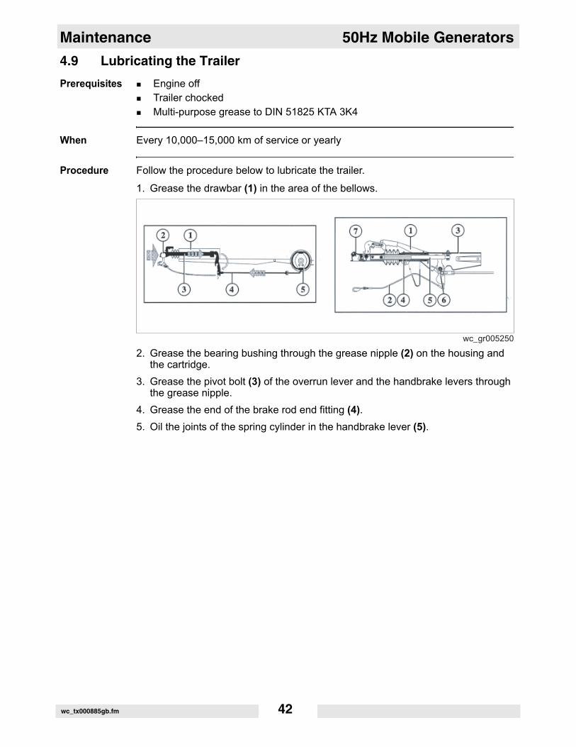
1. Grease the drawbar (1) in the area of the bellows.
2. Grease the bearing bushing through the grease nipple (2) on the housing and the cartridge.
3. Grease the pivot bolt (3) of the overrun lever and the handbrake levers through the grease nipple.
4. Grease the end of the brake rod end fitting (4).5. Oil the joints of the spring cylinder in the handbrake lever (5).
wc_gr005250
wc_tx000885gb.fm 42
50Hz Mobile Generators Maintenance
4.10 Cleaning the EnginePrerequisites Engine offEngine cool
When Every 1000 hours of service or yearly
Procedure Follow the procedure below to clean the engine.
1. Cover electric/electrical components and connection: alternator, starter, gover-nor, solenoid.
2. Blow compressed air through the engine stating with the exhaust side. Take care not to damage cooling fins of cooling system.
3. Cold water jet or steam cleaning is allowed. Limit pressure to 60 bar and tem-perature to 90°C.
4. Remove the covering from electric/electrical components installed in step 1.5. Start engine and allow remaining water to evaporate.
Note: Refer to the Deutz engine manual for detailed information on maintaining the engine.
wc_tx000885gb.fm 43
Maintenance 50Hz Mobile Generators
4.11 Changing/Tensioning Alternator V-BeltPrerequisites Engine offNew alternator V-belt
When Every 2000 hours of service or every 2 years
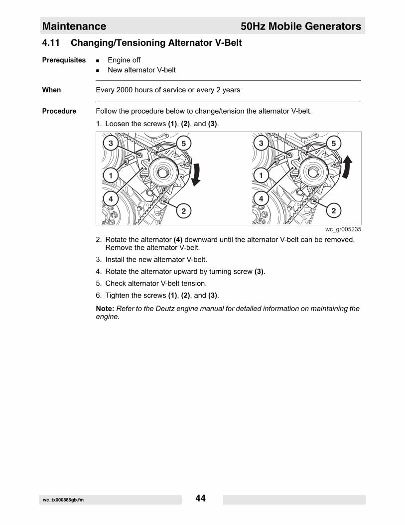
Procedure Follow the procedure below to change/tension the alternator V-belt.
1. Loosen the screws (1), (2), and (3).
2. Rotate the alternator (4) downward until the alternator V-belt can be removed. Remove the alternator V-belt.
3. Install the new alternator V-belt.4. Rotate the alternator upward by turning screw (3).5. Check alternator V-belt tension.6. Tighten the screws (1), (2), and (3).
Note: Refer to the Deutz engine manual for detailed information on maintaining the engine.
wc_tx000885gb.fm 44

50Hz Mobile Generators Maintenance
4.12 Checking/Adjusting Valve ClearancesPrerequisites Engine off and coolCylinder head gasket Feeler gauges
When Every 1000 hours of service or yearly
Procedure Follow the procedure below to check/adjust the valve clearances.
1. Turn the crankshaft until both valves in cylinder 1 overlap (exhaust valve about to close, inlet valve about to open). Position 1 of diagram below.
2. Adjust the valves marked in black in position 1 of diagram.3. Remove the cylinder head cover.
This procedure continues on the next page.
wc_tx000885gb.fm 45
Maintenance 50Hz Mobile Generators
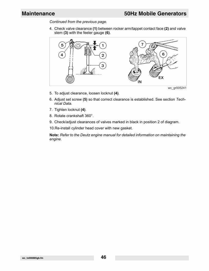
Continued from the previous page.4. Check valve clearance (1) between rocker arm/tappet contact face (2) and valve stem (3) with the feeler gauge (6).
5. To adjust clearance, loosen locknut (4).6. Adjust set screw (5) so that correct clearance is established. See section Tech-
nical Data.7. Tighten locknut (4).8. Rotate crankshaft 360°. 9. Check/adjust clearances of valves marked in black in position 2 of diagram. 10.Re-install cylinder head cover with new gasket.
Note: Refer to the Deutz engine manual for detailed information on maintaining the engine.
wc_tx000885gb.fm 46
50Hz Mobile Generators Maintenance
4.13 Checking Battery ElectrolytePrerequisites Engine off & coolDistilled water
When Every 250 hours of service or every 3 months
Procedure Follow the procedure below to check the battery electrolyte.
1. Disconnect the battery.
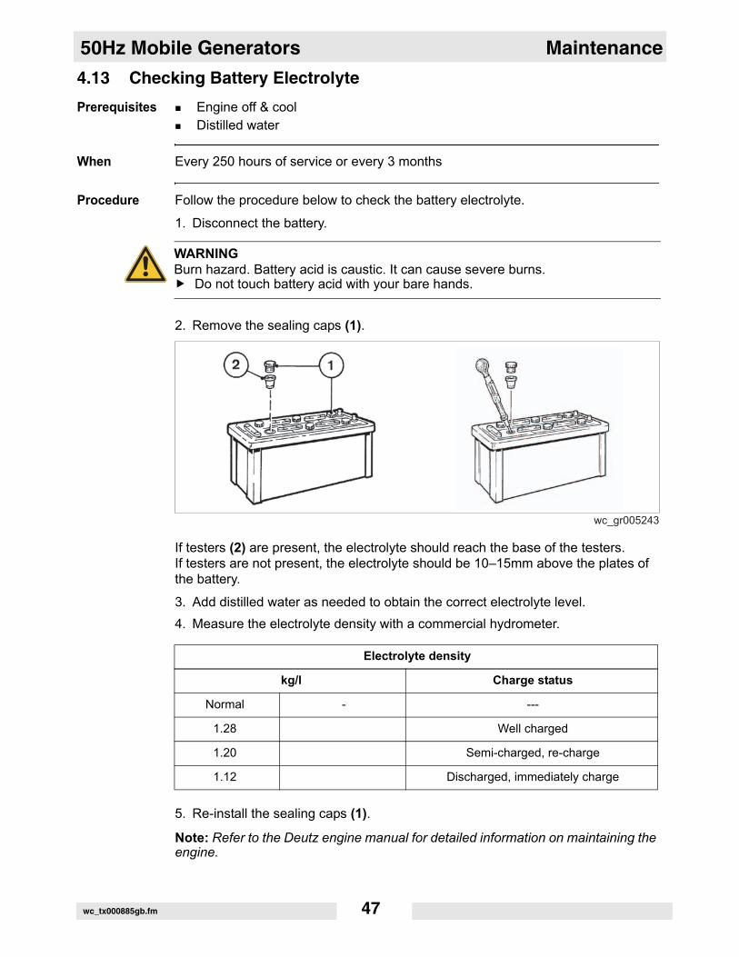
2. Remove the sealing caps (1).
If testers (2) are present, the electrolyte should reach the base of the testers.If testers are not present, the electrolyte should be 10–15mm above the plates of the battery.
3. Add distilled water as needed to obtain the correct electrolyte level.4. Measure the electrolyte density with a commercial hydrometer.
5. Re-install the sealing caps (1).
Note: Refer to the Deutz engine manual for detailed information on maintaining the engine.
WARNINGBurn hazard. Battery acid is caustic. It can cause severe burns.
Do not touch battery acid with your bare hands.
Electrolyte density
kg/l Charge status
Normal - ---
1.28 Well charged
1.20 Semi-charged, re-charge
1.12 Discharged, immediately charge
wc_tx000885gb.fm 47
Schematics 50Hz Mobile Generators
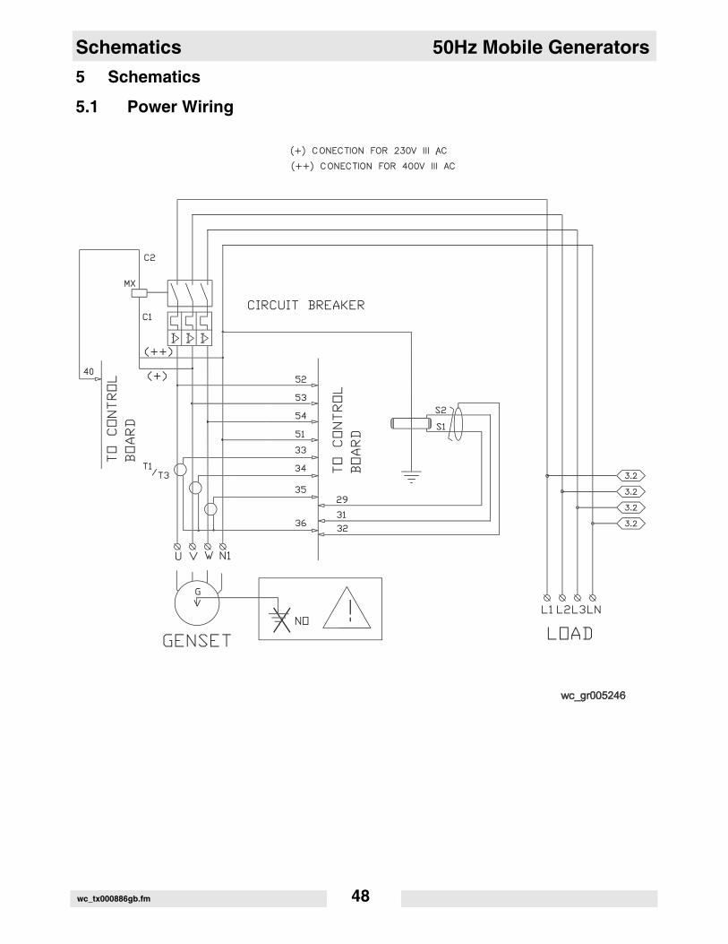
5 Schematics5.1 Power Wiring
wc_tx000886gb.fm 48
50Hz Mobile Generators Schematics
5.2 Power Wiring ComponentsComponents(+) Connection for 230V III AC(++) Connection for 230V III ACCircuit breakerLoadGensetTo control board
wc_tx000886gb.fm 49
Schematics 50Hz Mobile Generators
5.3 Engine Wiringwc_tx000886gb.fm 50
50Hz Mobile Generators Schematics
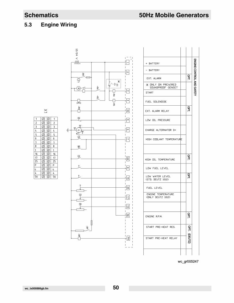
5.4 Engine Wiring ComponentsComponents+ Battery– BatteryAlarmEXT. (External) alarmStartFuel solenoidEXT. (External) alarm relayLow oil pressureCharge alternator D+ High coolant temperatureHigh oil temperatureLow fuel levelLow water level (standard Deutz 1012)Fuel levelEngine temperature (only Deutz 1012)Engine rpmStart pre-heat RES. (resistor)Start preheat relay
wc_tx000886gb.fm 51
Schematics 50Hz Mobile Generators
5.5 Socket Wiringwc_tx000886gb.fm 52

50Hz Mobile Generators Schematics
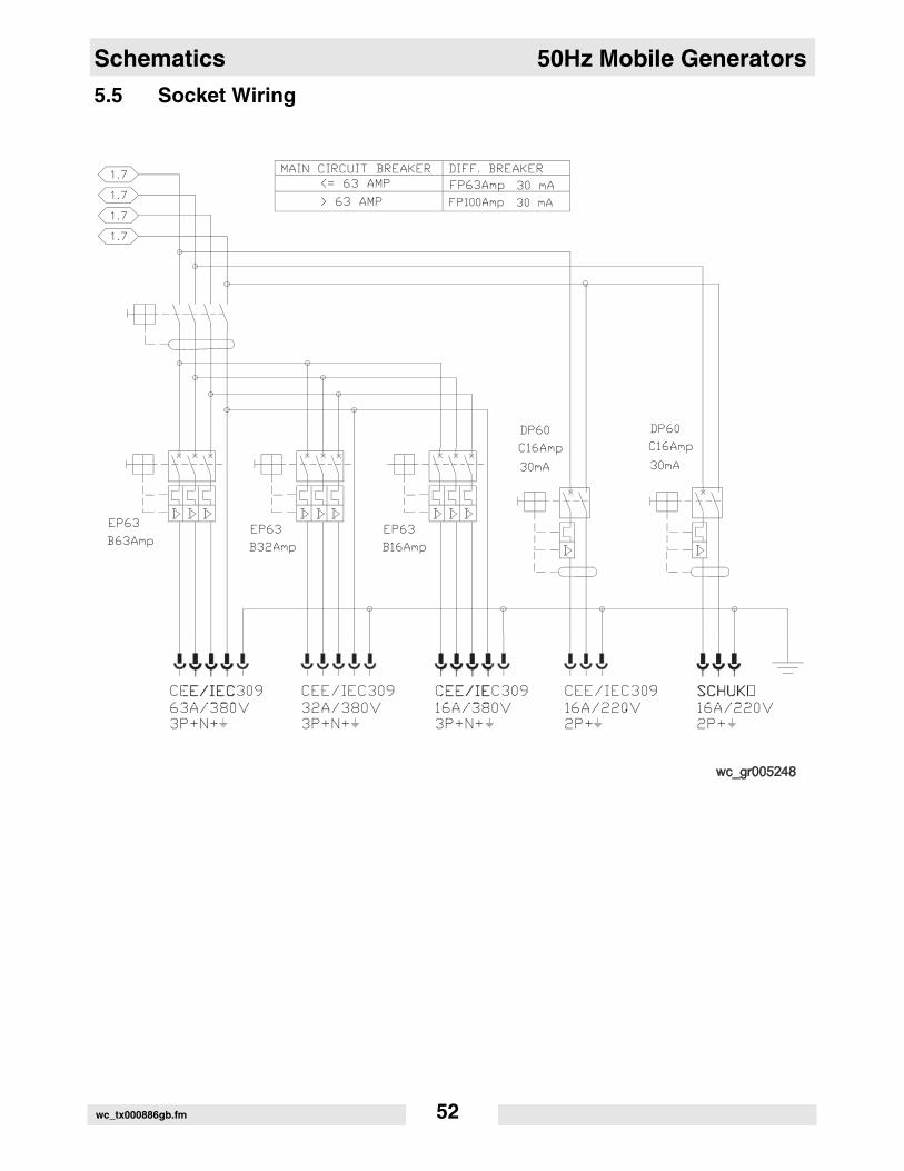
5.6 Socket Wirng ComponentsComponentsMain circuit breakerDIFF. (differential) breaker
wc_tx000886gb.fm 53
Schematics 50Hz Mobile Generators
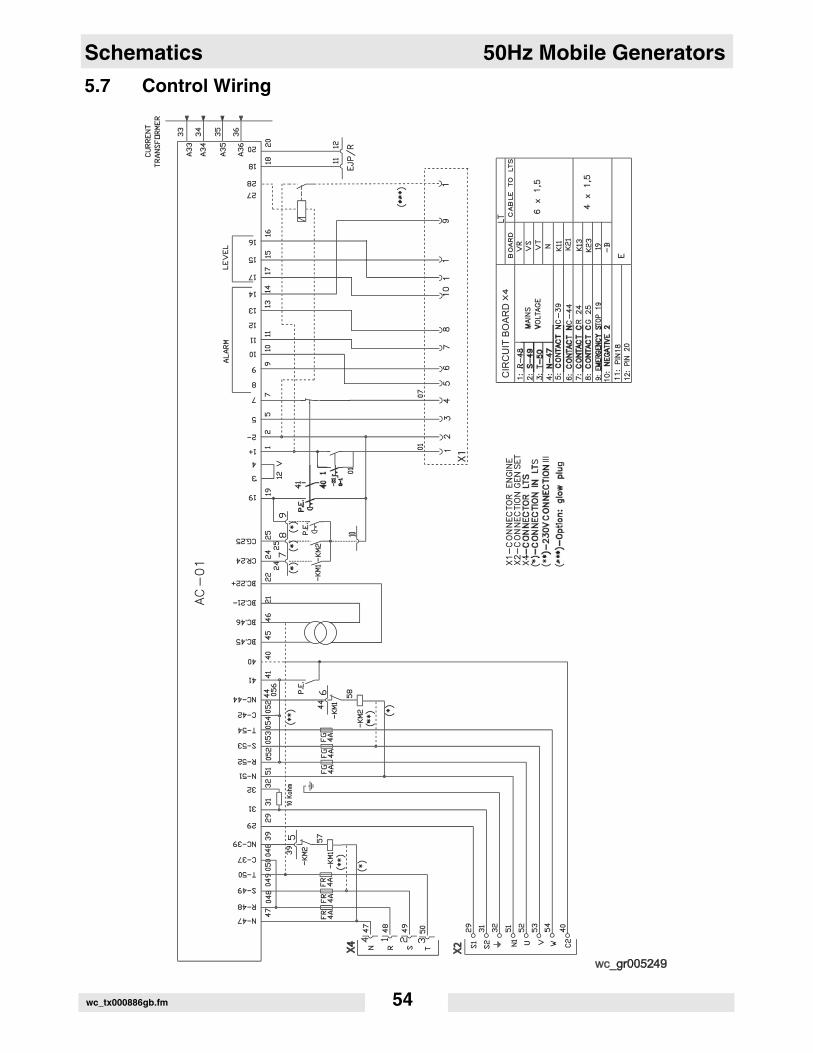
5.7 Control Wiringwc_tx000886gb.fm 54
50Hz Mobile Generators Schematics
5.8 Control Wiring ComponentsComponentsCurrent transformerX1-Connector engineX2-Connector gen setX4- Connector LTS (microprocessor)(**) 230V connection(***) Option: glow plugAlarmLevelCircuit boardMains voltageContactEmergency stopNegative 2Pin 18Pin 20BoardCable to LTS (microprocessor)AlarmLevel
wc_tx000886gb.fm 55
Basic Troubleshooting 50Hz Mobile Generators
wc_tx000896gb.fm 56
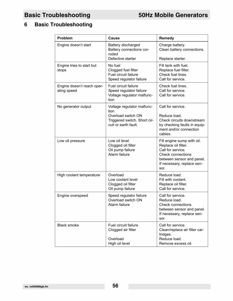
6 Basic Troubleshooting
Problem Cause Remedy
Engine doesn’t start Battery dischargedBattery connections cor-rodedDefective starter
Charge battery.Clean battery connections.
Replace starter.
Engine tries to start but stops
No fuelClogged fuel filterFuel circuit failureSpeed regulator failure
Fill tank with fuel.Replace fuel filter.Check fuel lines.Call for service.
Engine doesn’t reach oper-ating speed
Fuel circuit failureSpeed regulator failureVoltage regulator malfunc-tion
Check fuel lines.Call for service.Call for service.
No generator output Voltage regulator malfunc-tionOverload switch ONTriggered switch. Short cir-cuit or earth fault.
Call for service.
Reduce load.Check circuits downstream by checking faults in equip-ment and/or connection cables.
Low oil pressure Low oil levelClogged oil filterOil pump failureAlarm failure
Fill engine sump with oil.Replace oil filter.Call for service.Check connections between sensor and panel. If necessary, replace sen-sor.
High coolant temperature OverloadLow coolant levelClogged oil filterOil pump failure
Reduce load.Fill with coolant.Replace oil filter.Call for service.
Engine overspeed Speed regulator failureOverload switch ONAlarm failure
Call for service.Reduce load.Check connections between sensor and panel. If necessary, replace sen-sor.
Black smoke Fuel circuit failureClogged air filter
OverloadHigh oil level
Call for service.Clean/replace air filter car-tridges.Reduce load.Remove excess oil.
G 22 Technical Data
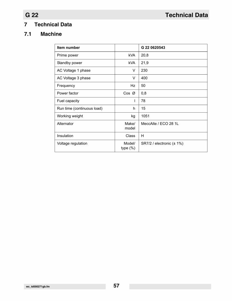
7 Technical Data7.1 Machine
Item number G 22 0620543
Prime power kVA 20,8
Standby power kVA 21,9
AC Voltage 1 phase V 230
AC Voltage 3 phase V 400
Frequency Hz 50
Power factor Cos Ø 0,8
Fuel capacity l 78
Run time (continuous load) h 15
Working weight kg 1051
Alternator Make/model
MeccAlte / ECO 28 1L
Insulation Class H
Voltage regulation Model/type (%)
SR7/2 / electronic (± 1%)
wc_td000271gb.fm 57
Technical Data G 22
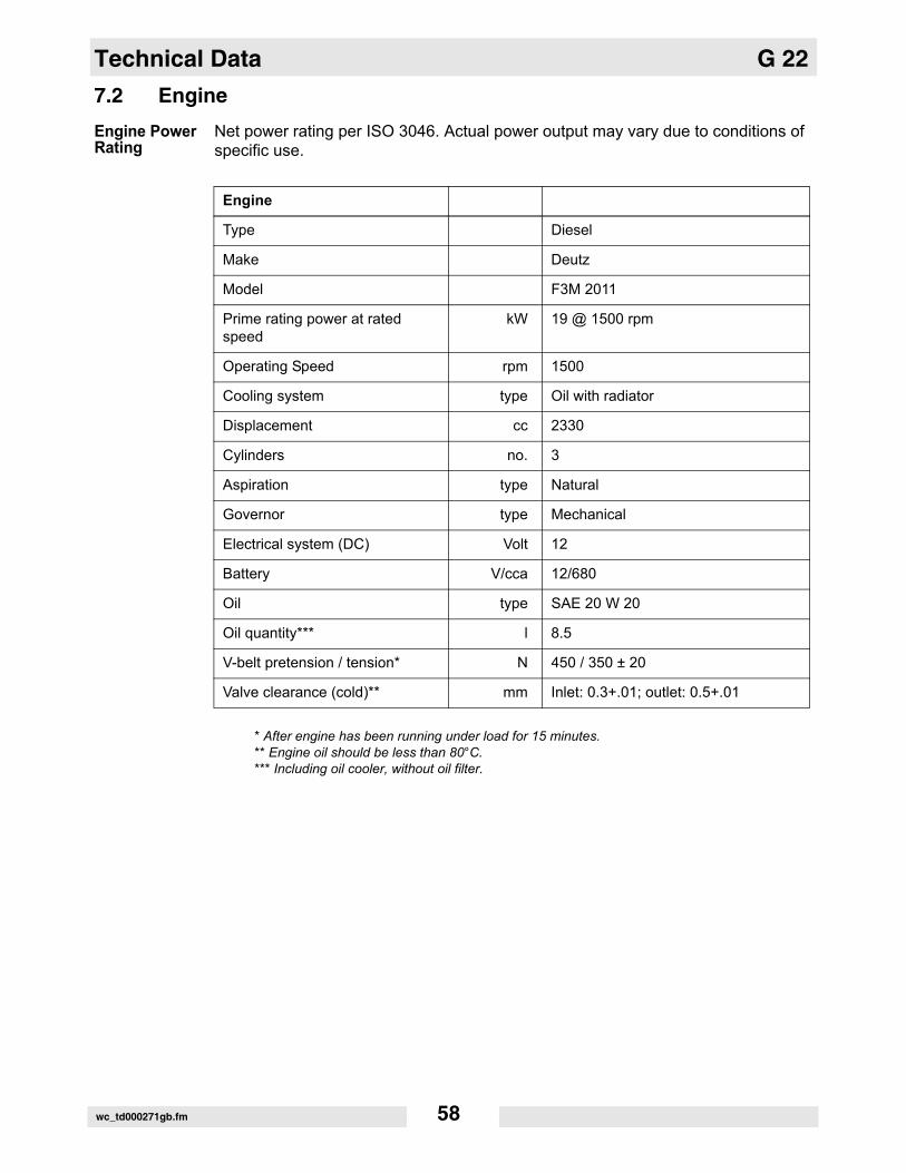
7.2 EngineEngine Power RatingNet power rating per ISO 3046. Actual power output may vary due to conditions of specific use.
* After engine has been running under load for 15 minutes.** Engine oil should be less than 80°C.*** Including oil cooler, without oil filter.
Engine
Type Diesel
Make Deutz
Model F3M 2011
Prime rating power at rated speed
kW 19 @ 1500 rpm
Operating Speed rpm 1500
Cooling system type Oil with radiator
Displacement cc 2330
Cylinders no. 3
Aspiration type Natural
Governor type Mechanical
Electrical system (DC) Volt 12
Battery V/cca 12/680
Oil type SAE 20 W 20
Oil quantity*** l 8.5
V-belt pretension / tension* N 450 / 350 ± 20
Valve clearance (cold)** mm Inlet: 0.3+.01; outlet: 0.5+.01
wc_td000271gb.fm 58
G 22 Technical Data
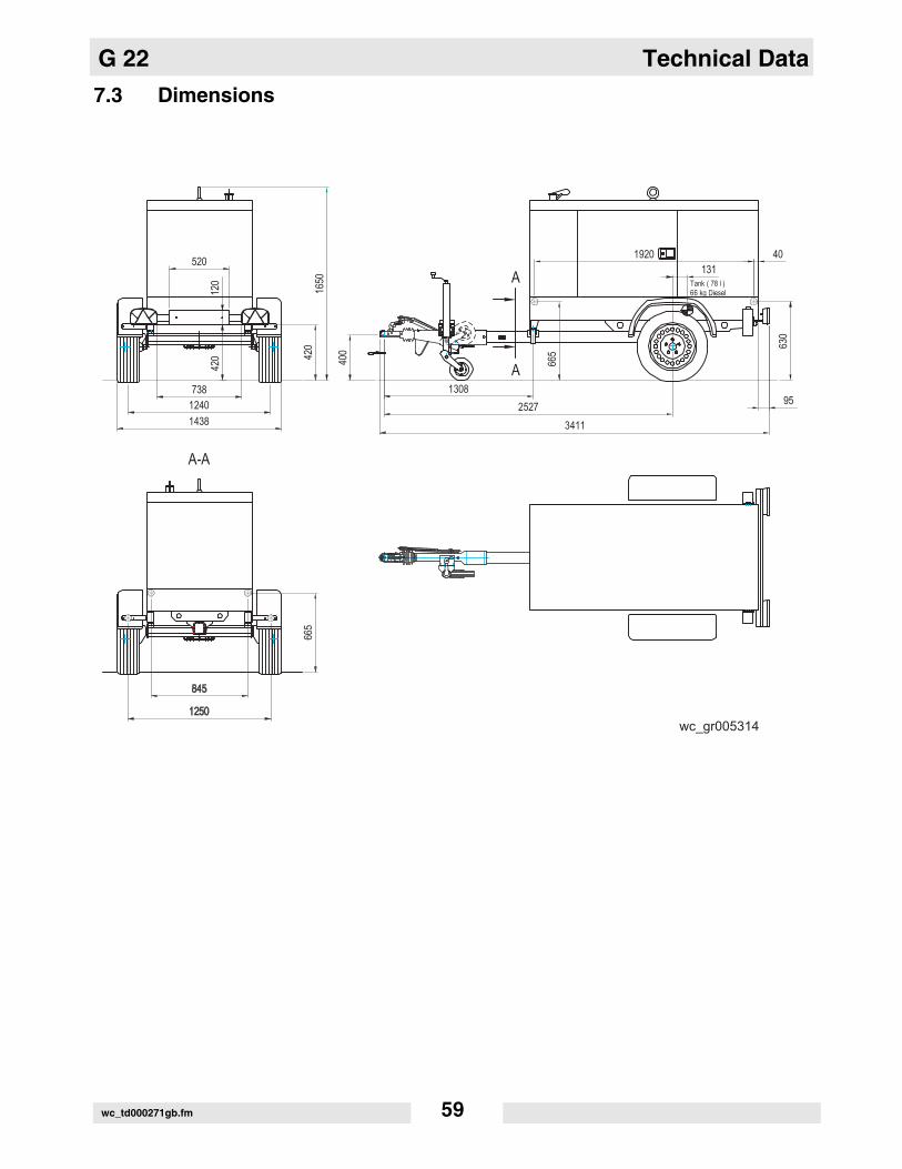
7.3 Dimensionswc_td000271gb.fm 59
Technical Data G 22
7.4 Sound SpecificationThe required sound specification, Paragraph 1.7.4.f of 89/392/EEC Machinery Directive, is:guaranteed sound power level (LWA) = 89 dB(A).This sound value was determined according to ISO 3744 for the sound power level (LWA).
wc_td000271gb.fm 60
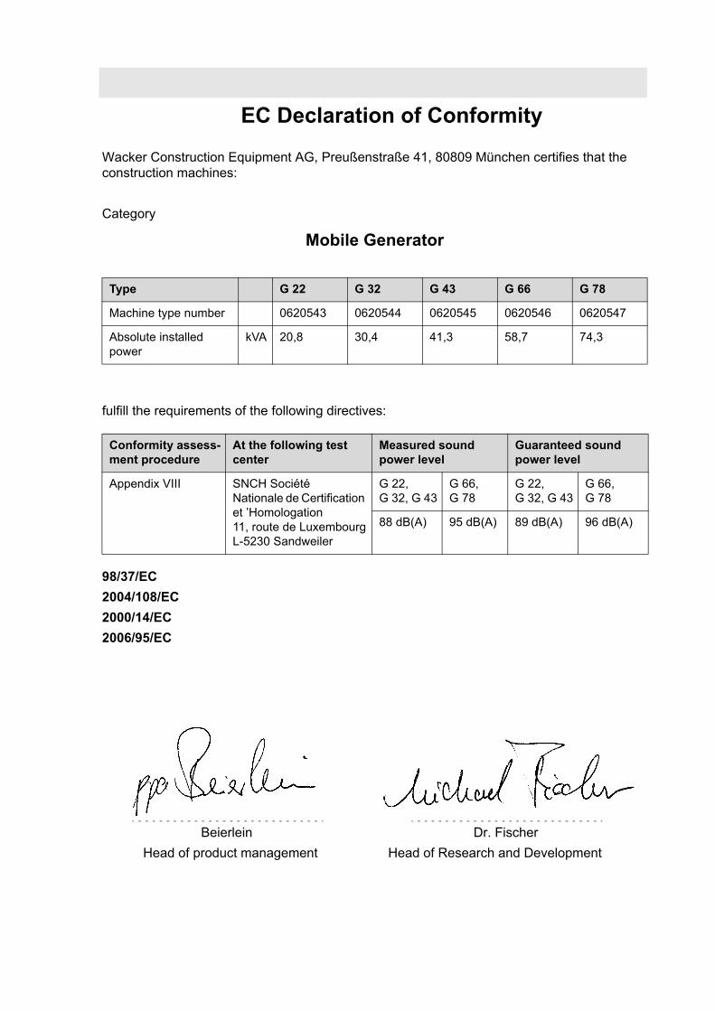
EC Declaration of Conformity
Wacker Construction Equipment AG, Preußenstraße 41, 80809 München certifies that the construction machines:
Category
Mobile Generator
fulfill the requirements of the following directives:
98/37/EC2004/108/EC2000/14/EC2006/95/EC
Type G 22 G 32 G 43 G 66 G 78
Machine type number 0620543 0620544 0620545 0620546 0620547
Absolute installed power
kVA 20,8 30,4 41,3 58,7 74,3
Conformity assess-ment procedure
At the following test center
Measured sound power level
Guaranteed sound power level
Appendix VIII SNCH Société Nationale de Certification et ’Homologation11, route de LuxembourgL-5230 Sandweiler
G 22, G 32, G 43
G 66, G 78
G 22,G 32, G 43
G 66, G 78
88 dB(A) 95 dB(A) 89 dB(A) 96 dB(A)
BeierleinHead of product management
Dr. FischerHead of Research and Development


Wacker Construction Equipment AG · Preußenstraße 41 · D-80809 München · Tel.: +49-(0)89-3 54 02 - 0 · Fax: +49 - (0)89-3 54 02-3 90Wacker Neuson Corporation · P.O. Box 9007 · Menomonee Falls, WI 53052-9007 · Tel. : (262) 255-0500 · Fax: (262) 255-0550 · Tel. : (800) 770-0957Wacker Asia Pacific Operations · Skyline Tower, Suite 2303, 23/F · 39 Wang Kwong Road, Kowloon Bay, Hong Kong · Tel. +852 2406 60 32 · Fax: +852 2406 60 21