wavelet decomposition based skewness and kurtosis...
TRANSCRIPT
1
AMSE JOURNALS-2016-Series: Advances B; Vol. 59; N° 1; pp 1-14
Submitted Jan. 2016; Revised April 16, 2016, Accepted May 15, 2016
Wavelet Decomposition based Skewness and Kurtosis Analysis for
Assessment of Stator Current Harmonics in a PWM – Fed Induction
Motor Drive during Single Phasing Condition
*A. Chattopadhyaya, **S. Chattopadhyay, ***J. N. Bera, ****S. Sengupta
*Electrical Engineering Department, SKFGI, WBUT, West Bengal, India,
** Electrical Engineering Department, Ghani Khan Chaoudhury Institute of Engineering &
Technology (under Ministry of HRD, Govt. of India), Malda, West Bengal, India
***Department of Applied Physics, University of Calcutta, 92 APC Road, Kolkata, West Bengal,
India ([email protected])
****Department of Applied Physics, University of Calcutta, 92 APC Road, Kolkata, West
Bengal, India ([email protected])
Abstract
Induction motors are widely used as electrical drives in industrial application for their good
efficiency and reliability in operation. This paper presents a fault detection method of a sinusoidal
PWM inverter fed induction machine during single phasing. Stator current harmonics are
analyzed by assessing kurtosis and skewness values of harmonic spectrums both at normal and at
fault condition. The observation is based on a model designed through computer simulation. The
mother wavelet used here is ‘db4’. The fault condition leads to changes in the values of skewness
and kurtosis which are very much optimistic to detect such fault condition in induction motor.
Key words
Discrete Wavelet Transform (DWT), kurtosis, skewness, single phasing.
1. Introduction
Induction motors are considered the main workhorse of the industry due to their ruggedness,
versatility and low manufacturing cost. Although Induction motors are simple reliable machines,

2
their annual failure rate is conservatively estimated at 3% per annum [1]. Thus, it has become an
important aspect to make the induction motors failure proof to reduce the down time of the
industries. For this purpose an early detection of motor faults is highly desirable by which any
catastrophic damage or any potentially dangerous situation can be avoided. A lot of study has
been done on the detection of these faults in induction motors where the motors have been
mathematically modeled [2] and different analysis techniques like motor current signature
analysis [3-4], Concordia analysis [5-6] and sequence components based assessment techniques
have been introduced for fault assessment. PWM fed Induction motors which are extensively
used in industries for their variable speed operation are more reliable than those supplied directly
online. Fuzzy logic has been used to detect faults modes of PWM fed induction motors [7]. Fuzzy
logic based systems, wavelet decomposition, PSD have been introduced for motor fault diagnosis
[8] – [10] along with Park and Clarke domain where different features of motor current have been
extracted to detect different faults in induction motor [11] – [16].
In this paper single phasing of a PWM fed induction motor has been considered. At normal
condition a three phase induction motor is fed by a sinusoidal PWM inverter. The fault single
phasing refers to loss of one of the three phases at the stator terminals. At this, condition negative
sequence component generates along with positive sequence components and the resultant stator
current increases. The negative sequence components have been assessed in [17]. The stator
current at single phasing has also been assessed using feature pattern extraction method [17].
Radar, Concordia and FFT based many fault diagnosis methods have been introduced [18] –
[20]. However, very little work has been done to use Kurtosis band Skewness in fault diagnosis.
This limitation has motivated this work.
In this paper, the stator current drawn by the induction motor from PWM inverter has been
analyzed by harmonics assessment using wavelet decomposition based technique. A stator
current measurement unit has been used to extract the current signal from the healthy phases and
Wavelet Transform algorithm is used to find the kurtosis and skewness values of the approximate
and detail coefficients which are compared for normal and faulty (unbalanced) conditions to
detect the single phasing.
2. Wavelet Transform
The frequency information of stationary and periodic waveform is produced by Fourier
Transform (FT). But it is not appropriate for a signal that has transitory characteristics such as
drifts, abrupt changes, and frequency trends. FT gives no information on the time instant at which
3
a particular frequency exists and only tells whether the frequency component exists or not.
Hence, FT is unsuitable for non-stationary signals. To overcome this problem, the Fourier
Transform has been adapted to analyze small sections of the signal at a time. This technique is
known as short-time Fourier transform (STFT), or windowing technique but its main drawback is
that only band of frequencies available at certain time intervals. Consequently, resolution
problem and problem with the size of window function arises. The wavelet transform was then
introduced with the idea of overcoming these difficulties mentioned above. A windowing
technique with variable-size region is then used to perform the signal analysis, which can be the
stator current, the case that is considered here. Wavelet analysis allows the use of long time
intervals where we want more precise low-frequency information, and shorter regions where we
want high-frequency information. In this paper ‘db4’ is considered as the mother wavelet.
3. Skewness and Kurtosis
To detect the single phasing condition two statistical parameters skewness and kurtosis are
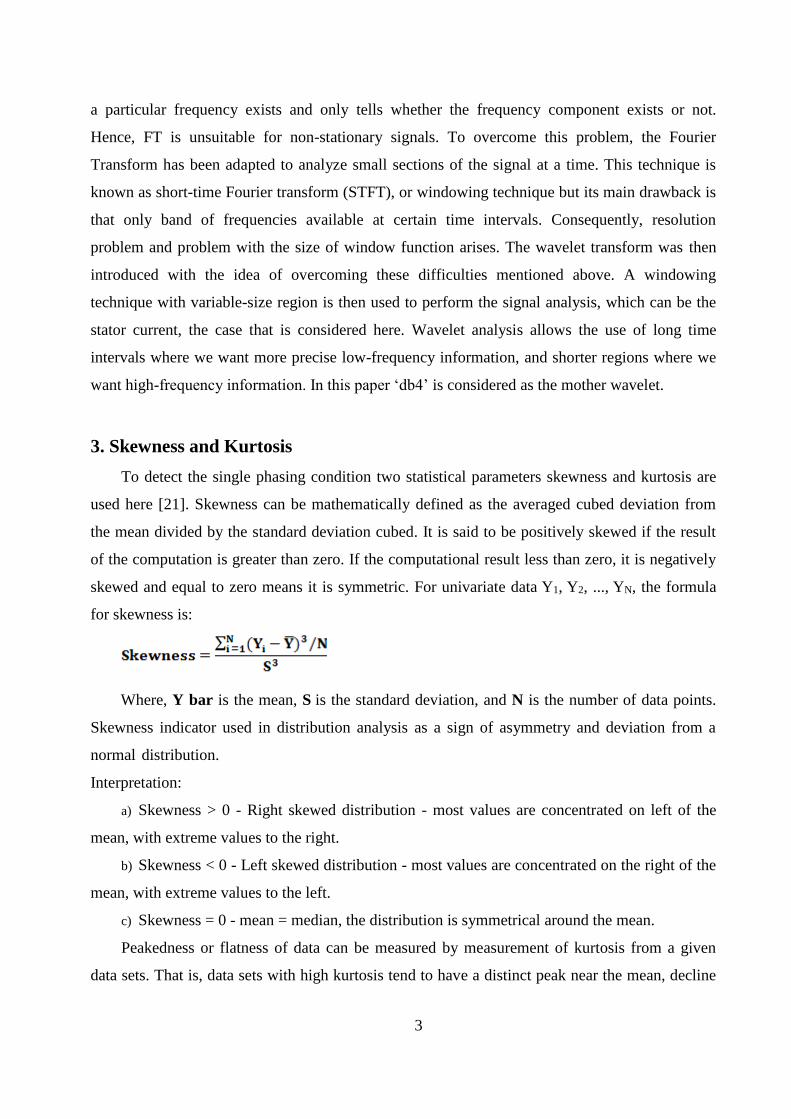
used here [21]. Skewness can be mathematically defined as the averaged cubed deviation from
the mean divided by the standard deviation cubed. It is said to be positively skewed if the result
of the computation is greater than zero. If the computational result less than zero, it is negatively
skewed and equal to zero means it is symmetric. For univariate data Y1, Y2, ..., YN, the formula
for skewness is:
Where, Y bar is the mean, S is the standard deviation, and N is the number of data points.
Skewness indicator used in distribution analysis as a sign of asymmetry and deviation from a
normal distribution.
Interpretation:
a) Skewness > 0 - Right skewed distribution - most values are concentrated on left of the
mean, with extreme values to the right.
b) Skewness < 0 - Left skewed distribution - most values are concentrated on the right of the
mean, with extreme values to the left.
c) Skewness = 0 - mean = median, the distribution is symmetrical around the mean.
Peakedness or flatness of data can be measured by measurement of kurtosis from a given
data sets. That is, data sets with high kurtosis tend to have a distinct peak near the mean, decline

4
rather rapidly, and have heavy tails. Data sets with low kurtosis tend to have a flat top near the
mean rather than a sharp peak. A uniform distribution would be the extreme case.
For univariate data Y1, Y2,..., YN, the formula for kurtosis is:
(1)
Where, Y bar is the mean, S is the standard deviation, and N is the number of data points.
Kurtosis [21] indicator used in distribution analysis as a sign of flattening or "peakedness" of a
distribution.
Interpretation:
a) Kurtosis > 3 - Leptokurtic distribution, sharper than a normal distribution, with values
concentrated around the mean and thicker tails. This means high probability for extreme values.
b) Kurtosis < 3 - Platykurtic distribution, flatter than a normal distribution with a wider peak.
The probability for extreme values is less than for a normal distribution, and the values are wider
spread around the mean.
c) Kurtosis = 3 - Mesokurtic distribution - normal distribution for example.
3. Computer Modeling
The total analysis has been done by computer simulation using MATLAB [22]. Here a 3ph
Induction Motor of rating 3HP, 220V, 1725rpm is used, which is fed by a sinusoidal PWM
inverter. The inverter uses a sinusoidal reference signal of 60Hz and a triangular wave of
frequency 1980Hz. The output is fed to relays which produces the 3ph of sinusoidal voltage
displaced by 120⁰ apart. Its output is then fed to the stator of the Induction Motor, through
Controlled Voltage Source. So, three phase balanced power is fed to the motor as shown in Fig.
1. The rotor of the motor is short-circuited and its stator leakage inductance is set to twice its
normal. The load torque is set to its nominal value of 11.9 N-m. Here in order to create a single
phase fault condition, Phase A was open circuited through a circuit breaker after some time of
motor starting and its effect on the other phases B & C was studied by connecting a current
measurement unit. The current signature obtained from phase B and phase C was analyzed
separately for normal and fault condition with the help of Discrete Wavelet Transform (DWT).
The Skewness and Kurtosis values are calculated in both the conditions for the approximate and
detail coefficients in each and every decomposition level (upto 9th level) to detect single phasing
fault.

5
Fig.1. Experimental Model for Assessment of Single Phasing of a PWM Fed Induction Motor
4. Stator Current Analysis
Current through phase A becomes zero in case of single phasing condition but currents through
other healthy phase B and C increases. Healthy phases’ currents are captured and then assessed
using Discrete Wavelet Transform (DWT). Here, well-known Daubechies wavelet ‘db4’
(properties: asymmetric and orthogonal) has been used as mother wavelet, where db4 scaling
functions are as follows:
(2)
and wavelets are as follows:
(3)
Healthy phase currents are decomposed at different DWT levels and at each level, the skewness
and kurtosis values of harmonics spectrum are assessed by measuring skewness and kurtosis
values. The wavelet decomposition based result obtained corresponding to healthy phases B and
C ( for normal and faulty condition) is shown graphically in Fig. 2, 3, 4, 5, 6, 7, 8, and 9.
Dashed line corresponds to single phasing condition (fault or unbalanced condition) and solid
continuous line corresponds to normal condition for all the mentioned figures.

6
Fig.2. Kurtosis Values of Approximate Coefficients for Phase B Current Plotted with Respect to
DWT Decomposition Level
In Fig.2, Kurtosis values of approximate coefficients for B Phase Current are plotted with respect
to DWT decomposition levels. It shows almost constant value both at normal and fault condition.
Fig.3. Kurtosis Values of Approximate Coefficients for Phase C Current Plotted with Respect to
DWT Decomposition Level
In Fig.3, Kurtosis values of approximate coefficients for C Phase Current are plotted with respect
to DWT decomposition levels. It shows almost constant value both at normal and fault condition.

7
Fig.4. Kurtosis Values of Detail Coefficients for Phase B Current Plotted with Respect to DWT
Decomposition Level
In Fig.4, Kurtosis values of detail coefficients for B Phase Current are plotted with respect to
DWT decomposition levels. It shows almost constant value up to level 6, maximum at level 7 and
then negative slope for both normal and fault condition.
Fig.5. Kurtosis Values of Detail Coefficients for Phase C Current Plotted with Respect to DWT
Decomposition Level
In Fig.5, Kurtosis values of detail coefficients for C Phase Current are plotted with respect to
DWT decomposition levels. It shows almost constant value up to level 6, maximum at level 7 and
then negative slope for both normal and fault condition.

8
Fig.6. Skewness Values of Approximate Coefficients for Phase B Current Plotted with Respect to
DWT Decomposition Level
In Fig.6, Skewness values of approximate coefficients for B Phase Current are plotted with
respect to DWT decomposition levels. It shows almost constant value both at normal and fault
condition.

9
Fig.7. Skewness Values of Approximate Coefficients for Phase C Current Plotted with Respect to
DWT Decomposition Level
In Fig.7, Skewness values of approximate coefficients for C Phase Current are plotted with
respect to DWT decomposition levels. It shows almost constant value both at normal and fault
condition.
Fig.8. Skewness Values of Detail Coefficients for Phase B Current Plotted with Respect to DWT
Decomposition Level
In Fig.8, Skewness values of detail coefficients for B Phase Current are plotted with respect to
DWT decomposition levels. It shows almost constant value up to level 6, minimum at level 7 and
then positive slope for both normal and fault condition.

10
Fig.9. Skewness Values of Detail Coefficients for Phase C Current Plotted with Respect to DWT
Decomposition Level
In Fig.9, Skewness values of detail coefficients for C Phase Current are plotted with respect to
DWT decomposition levels. It shows almost constant value up to level 6, maximum at level 7 and
then positive slope for both normal and fault condition.
5. Observation
In this paper single phasing have been done in phase A and current signature is captured
from phase B and phase C. Discrete Wavelet Transform (‘db4’ is taken as a mother wavelet) is
used to decomposed phase B and C current and skewness and kurtosis values have been
calculated for detail and approximate coefficients for both the conditions to detect the faulty
condition.
The kurtosis values of approximate coefficients for phase B and phase C during the normal
and fault condition have been plotted in Fig. 2 and Fig. 3 respectively. There is a clear difference
between these two plots, which clearly suggests the faulty condition.
Fig. 6 and Fig. 7 depict the skewness values of approximate coefficients in both the
conditions (normal and fault) for phase B and C current respectively. In these two plots clearly
there is a difference between normal and fault condition.
Fig. 4 and Fig. 5 are used for comparison of Kurtosis values of detail coefficients for phase
B and C current in normal and fault conditions respectively. In these figures the differences arise
from DWT decomposition level 6 and maximum difference are observed in DWT decomposition
11
level 7. Fig. 8 depicts the skewness values of detail coefficients for phase-B current in normal and
faulty conditions, where the differences between the two plots are started at DWT decomposition
level 6 and it is minimum at DWT decomposition level 7. In Fig. 9 the Skewness values of detail
coefficients for phase-C current have been plotted in normal and faulty conditions where the
difference is maximum at DWT decomposition level 7 which clearly suggests the single phasing
condition in PWM fed induction motor.
6. Single Phasing Detection Algorithm
An algorithm for single phasing or fault detection has been also made as follows:
a. Step down the stator currents through current transformer
b. Sample them at proper sampling frequency
c. Capture the sampled values through data acquisition system
d. If the value of captured signal is zero, then faulty condition can be assessed, otherwise
e. Apply discrete wavelet transform technique on the captured signal
f. Determine skewness and kurtosis values of approximate and detail coefficients from DWT
decomposition levels (upto 9th level)
g. Compare all above values from standard or normal condition measured values
h. Diagnose the single phasing or faulty condition based on measurement and comparison of
above parameters values in two conditions.
7. Conclusion
In this paper skewness and kurtosis values of approximate and detail coefficients of
harmonic spectrums have been measured in normal and faulty condition to detect the single
phasing condition of a PWM fed induction motor. Though single phasing was occurred in phase
A and DWT have been done for healthy phases (B and C) current and all the parameters have
been calculated thereafter. The observation shows clear difference of those parameters at faulty
condition from normal condition. This indicates that continuous measurement, monitoring and
comparison can be done for diagnosis of fault like single phasing. Another clear observation can
be noted that when single phasing occurs in phase A, its effect falls on phase B and phase C
significantly. The kurtosis value of approximate coefficients decreases and skewness value of
approximate coefficients increases many folds in case of fault condition which can be easily
noted from the above depicted figures.

12
References
1. T.C. Akuner, H. Calik, “Analysis of balanced three phase induction motor performance under
unbalanced supply using simulation and experimental results”, Electronics and Electrical
Engineering, Elektronika IR Electrotechnika, ISSN-1392-1215, no.3(109), pp. 41-45, 2011.
2. J.H. Jung, J.J. Lee and B.H. Kwon, “Online diagnosis of induction motors using MCSA”,
IEEE Transactions on Industrial Electronics, vol. 53, no. 6, pp. 1842–1852, December 2006.
3. Systems Applications, Engineering and Development vol 1, issue 1, pp. 13 – 17, 2007.
4. D.G. Dorrel, W.T. Thomson and S. Roach, “Analysis of airgap flux, current and vibration
signals as a function of the combination of static and dynamic airgap eccentricity in 3-phase
Induction motors”, IEEE Trans. on Industr. Applications, vol. 33, pp. 24 – 34, 1997.
5. F. Zidani, M.E.H. Benbouzid, D. Diallo, and Md.S.N. Saïd, “Induction motor stator faults
diagnosis by a current concordia pattern-based fuzzy decision system”, IEEE Transaction on
Energy Conversion, vol. 18, no. 4, pp. 469 – 475, December 2003.
6. D. Diallo, M.E.H. Benbouzid, D.Hamad, and X. Pierre, “Fault detection and diagnosis in an
induction machine drive: a pattern recognition approach based on concordia stator mean
current vector”, IEEE Transaction on Energy Conversion, vol. 20, no. 3, pp. 512 – 519,
September 2005.
7. M.E.H. Benbouzid, “A review of induction motor signature analysis as a medium for fault
detection”, IEEE Trans Ind. Electron., vol. 47, issue 5, pp. 984 – 993, 2000.
8. F. Zidani, D. Diallo, M.E.H. Benbouzid, R.N. Saïd, “A Fuzzy-based approach for the
diagnosis of fault modes in a voltage-fed PWM inverter induction motor drive”, IEEE
Transactions On Industrial Electronics, vol. 55, no. 2, February 2008.
9. J. Cusido, L. Romeral, J. A. Ortego, J. A. Rosero and A. G. Espinosa, “Fault detection in
induction machines using power spectral density in Wavelet decomposition”, IEEE
Transactions on Industrial Electronics, vol. 55, no. 2, pp. 633 – 643, February, 2008.
10. J. Cusido, A. Jornet, L. Romeral, J. A. Ortega and A. Garcia, “Wavelet and PSD as a fault
detection technique”, ITMC 2006-Instrumentation and Measurement Technology Conference,
proceeding of IEEE, Sorrento, Italy, pp. 1397 – 1400, 24-27 April, 2006.
11. M. E. H. Benbouzid et al, “Monitoring and diagnosis of Induction motor electrical faults
using a current Park's vector pattern approach”, Proc. of IEEE Int. Conf. On Electrical
Machines and Drives, Seattle, WA, pp. 275 – 277, 1999.

13
12. H. Nejjariet al., “Monitoring and diagnosis of induction motors electrical faults using a
current Park’s vector pattern learning approach”, IEEE Trans. Ind. Appl., vol. 36, no. 3, pp.
730 – 735, May/Jun. 2000.
13. S. Chattopadhyay, M. Mitra, and S. Sengupta: “Harmonic Analysis in a Three-Phase System
using Park Transformation Technique”, International Journal on Modeling, Measurement and
Control of General Physics and Electrical Applications, AMSE, Series –A, vol. 80, No–3,
Modeling-A, pp. 42-58, 2007.
14. S. Chattopadhyay, M. Mitra, and S. Sengupta: “Electric Power Quality”, Springer, 2010, first
edition, ISBN: 978-94-007-0634-7.
15. S. Chattopadhyay, S. Karmakar, M. Mitra, S. Sengupta.: ‘Assessment of crawling of an
induction motor by stator current Concordia analysis’, Electron. Lett., vol. 48, Issue 14, pp.
841–842, 5th July 2012.
16. S. Chattopadhyay, M. Mitra, S. Sengupta,“Area based approach in power quality
assessment”, International Journal of Power Management Electronics, ID-147359, Pages-6,
ISSN: 16876679, May 2008.
17. S. Chattopadhyay, S. Karmakar, M. Mitra, S. Sengupta, “Symmetrical components and
current Concordia based assessment of single phasing of an induction motor by feature
pattern extraction method and Radar analysis”, International Journal of Electrical Power and
Energy Systems (Elsevier), vol. 37, Issue 1, pp. 43 – 49, May 2012.
18. S Chattopadhyay, S Karmakar, M Mitra, S Sengupta, Radar Analysis of Stator Current
Concordia for Diagnosis of Unbalance in Mass and Cracks in rotor bar of an Squirrel Cage
Induction Motor, International Journal on Modeling, Measurement and Control of General
Physics and Electrical Applications, AMSE, Series -A, vol. – 85, issue – 1, pp – 50-61, 2012.
ISSN: 1259-5985.
19. S Chattopadhyay, S Karmakar, M Mitra, S Sengupta, Loss of phase fault detection of an
induction motor, International Journal on Modeling, Measurement and Control of General
Physics and Electrical Applications, AMSE, Series -A, vol. – 85, issue – 2, pp – 18-34, 2011,
ISSN: 1259-5985.
20. S Chattopadhyay, M Mitra, S Sengupta, Part wise linear characteristics of FFT based
spectrum of Current Transformer, International Journal on Modeling, Measurement and
Control of General Physics and Electrical Applications, AMSE, Series -A, Vol. 84, Issue 1,
2011, pp 89-98, ISSN: 1259-5985.

14
21. “Engineering Statistics Handbook”, NIST/SEMATECH e-Handbook of Statistical
Methods, NIST, Retrieved 18th March 2012.
22. MATLAB® 7.7 (MATLAB demos).