waveform design for cognitive radar with deterministic...
TRANSCRIPT
Int. J. Communications, Network and System Sciences, 2016, 9, 250-268 Published Online June 2016 in SciRes. http://www.scirp.org/journal/ijcns http://dx.doi.org/10.4236/ijcns.2016.96023
How to cite this paper: Karimi, V., Mohseni, R., Norouzi, Y. and Dehghani, M.J. (2016) Waveform Design for Cognitive Radar with Deterministic Extended Targets in the Presence of Clutter. Int. J. Communications, Network and System Sciences, 9, 250-268. http://dx.doi.org/10.4236/ijcns.2016.96023
Waveform Design for Cognitive Radar with Deterministic Extended Targets in the Presence of Clutter Vahid Karimi1*, Reza Mohseni1, Yaser Norouzi2, Mohammad Javad Dehghani1 1Department of Electrical Engineering, Shiraz University of Technology, Shiraz, Iran 2Department of Electrical Engineering, Amirkabir University of Technology, Tehran, Iran
Received 24 January 2016; accepted 21 June 2016; published 24 June 2016
Copyright © 2016 by authors and Scientific Research Publishing Inc. This work is licensed under the Creative Commons Attribution International License (CC BY). http://creativecommons.org/licenses/by/4.0/
Abstract Adjusting radar transmitted waveform to its environment is one of the most important roles in cognitive radar; having the capability of updating transmitted waveforms in different applications is a key point. It has been shown in many studies that if the waveform is designed according to the target and clutter characteristics, the detection performance will improve significantly. The un-certainty of the target radar signatures decreases via maximizing MI and the probability of ex-tended target detection is increases via maximizing SNR. In this paper, a waveform design ap-proach based on maximizing both SNR and MI and with regard to target and clutter shape is pre-sented. The detection performance for proposed waveform is compared with previous proposed waveforms. The present paper compares different scenarios of target and clutter and using the probability of detection as a cost function to investigate the advantages and disadvantages of each waveform in different scenarios which are mainly discussed in this text. The desired waveform for cognitive radar is selected based on simultaneously making compromises between SNR and MI, which plays an important role in cognitive radar systems and based on the assumption addressed in the text, the best waveform transmitted into the environment.
Keywords Signal to Noise Ratio, Mutual Information, Cognitive Radar, Deterministic Extended Target, Clutter
1. Introduction Cognitive radar is a radar system which selects its transmitted waveform to adapt to the radar environment by
*Corresponding author.

V. Karimi et al.
251
using feedback structure from the receiver to the transmitter. In these systems waveforms can be adaptively op-timized based on preceding knowledge about the targets and environments; it leads to the improvement of the total performance of system [1]. Design of transmitting waveform has an important effect on the performance and efficiency of radar system. Adaptive waveform design for target detection and recognition has been devel-oped during the past decade, and also recently most studies have been devoted to radar waveform optimization. In these approaches, one method is based on signal-to-noise ratio (SNR) maximizing under a particular model of the system, interference, clutter and targets [2]. Another approach is based on mutual information which is first proposed by Bell [3]. Bell shows for estimating the parameters of a target from a given ensemble, the radar waveform should be designed to maximize the mutual information between the received signal and the target ensemble [4]. SNR-based optimum matched waveform for a specific target via frequency domain approach is proposed in [5]. An optimal waveform for T-72 and M1 main battle tanks detection is proposed in [6].
The information-based approach in the presence of signal-dependent clutter is investigated in [7]. In their work, optimum waveform is investigated both from SNR maximization and information-theoretic approaches. The optimal waveform for detecting extended target in signal-dependent interference is proposed in [8]. They derive optimal waveform energy spectral density (ESD) by maximizing SNR. A method for waveform design based on mutual information is proposed in [9] in which the general water-filling method is utilized to solve the waveform design for the recognition of multiple extended targets. They have shown that their proposed method has the higher classification rate at higher SNRs and higher detection performance in lower SNRs as compared to LFM and water-filling signals. In [10], the performance of waveform design in cognitive radar is discussed and a new iterative algorithm is proposed to synthesize a constant modulus waveform to maximize SNR and MI simultaneously. Designing matched waveforms based on maximizing SNR and MI for both deterministic and stochastic targets are discussed in [11] [12]; using multiple transmission of obtaining waveform a target identi-fication problem is investigated. A new technique is proposed in [13], which improves the classification perfor-mance of SNR-based matched waveforms. In [7] [14], a closed-loop strategy is applied to discriminate target classes rather than a finite ensemble of known targets. In [15], optimization problem based on mutual informa-tion for waveform design in signal dependent clutter is discussed and a new waveform using interior-point me-thod to carry out the optimization task is proposed. In previous papers such as [8] [16], SNR improvement for proposed waveforms over LFM waveform is investigated and in this paper, we evaluate SNR and MI values for different waveforms and compare the results with LFM waveforms and show the best performance of obtaining waveforms.
The contributions of this paper include an analysis of applying both the information-based and SNR-based approach to different deterministic extended targets and clutter scenarios considering the energy constraint. In this study, energy distribution for optimum waveform in clutter and noise scenario with the energy constraint have been addressed and we focus on the point that waveform should put a considerable amount of available energy on the frequency bands in which the target spectrum frequency components is considerable while the clutter is negligible. We derive various waveforms for each scenario and finally compare our results with linear frequency modulated (LFM) waveform to verify the performance of the proposed waveform.
This paper is organized as follows: first a radar system model is described in Section 2 and then the derivation of MI-based and SNR-based waveforms in the presence of Gaussian clutter and other scenarios are derived. In Section 3, using the obtained relations in Section 2, transmit waveform spectrum for two deterministic extended targets are illustrated and the energy allocation realized by obtaining waveforms are briefly discussed. Section 4 generally discusses the performance of obtaining waveforms and other predefined waveforms and a new closed-loop structure for detecting targets in different scenarios is proposed. Finally, in Section 5, we provide a general conclusion.
2. Problem Formulation 2.1. Signal, Clutter and Target Model To analyze a radar system, all constituent blocks should be defined. We consider a signal model of a Gaussian extended target in the presence of clutter as shown in Figure 1. Now we define the essential target and clutter models to analyze the overall performance of a radar system.
Let x(t) be a finite-energy waveform with duration T. We assume x(t) is energy-limited and non-zero only in the time interval 2t T≤ which has a bandwidth w; The energy content of this signal is:

V. Karimi et al.
252
h(t)
c(t)
+x(t) y(t)
n(t)
Figure 1. Known Gaussian extended target model in the presence of clutter [7].
( ) 22
2
dT
TxE x t t
−
= ∫ (1)
c(t) is assumed to be sea clutter with known power spectral density (PSD) which can be approximated as fol-lows:
( ) ( )2
2exp2
cc c
c
f fP f g
σ
− = −
(2)
Here fc is the peak locations of the Gaussian function; gc and 2cσ are parameters which are specified accord-
ing to problem conditions. h(t) is the impulse response of target. Once the impulse responses are generated, it is assumed that they are exactly known to the transmitter. In this study, target is assumed to have a Gaussian mix-ture shape with the following power spectral density:
( ) ( )22
0 21
exp2
Ni
ii T
f fH f a a
σ=
− = + −
∑ (3)
where ai and fi are respectively determined between a specific amplitude range and an appropriate interval due to clutter and noise specifications. The variance 2
Tσ is supposed to have a constant value. Finally n(t) denotes the noise, which is a complex zero mean WSS Gaussian random process with known PSD Pn(f). Now let r(t) be the received signal that is equal to:
( ) ( ) ( ) ( ) ( ) ( )r t x t h t x t c t n t= ∗ + ∗ + (4)
2.2. Waveform Derivation In this part, the Energy Spectral Density (ESD) of MI-based is computed with the assumption of known target in different scenarios and compared with SNR-based waveform discussed in [8]. Like [11], using Lagrangian mul-tiplier, we have derived optimum waveform ESD based on MI criteria in both signal-dependent interference and signal-independent noise. The MI between a Gaussian target ensemble and the received signal without the pres-ence of clutter is equal to:
( ) ( ) ( )( ) ( ) ( )( )
2 2
; | ln 1 dh
Wn
X f fMI r t h t x t f
P fσ
= +
∫ (5)
where ( )2h fσ is the continuous target signature. Now let εx(f) be the energy spectral density (ESD) of the
waveform, so we have:
( ) ( )( )
2
ln 1 dx hW
n
f fMI f
P fε σ
= +
∫ (6)

V. Karimi et al.
253
The desired waveform ESD is found by solving the constrained optimization problem:
( ) ( )ˆ maxxx ff MIεε = (7)
With the energy constraint:
( )ˆ dx xWf f Eε =∫ (8)
Now using the Lagrangian multiplier method, the waveform ESD will be obtained as follows:
( )( ) ( ) ( )( ) ( )( )
( ) ( )( ) ( )
2
2
ln 1 d d
ln 1 d
x hx x xW W
n
x hx xW
n
f fL f f E f f
P f
f ff f E
P f
ε σε λ ε
ε σλε λ
= + + −
= + − +
∫ ∫
∫ (9)
We can equivalently maximize:
( )( ) ( ) ( )( ) ( )
2
ln 1 x hx x
n
f fL f f
P fε σ
ε λε
= + −
(10)
The first and the second derivatives of ( )( )xL fε with respect to εx(f) are given by:
( )( )( )
( )( )
( ) ( )( )
( )( )( )
( )( )
( ) ( )( )
2
2
22
2
2 22
dd
1
dd
1
x n
x
xn
nx
x
xn
H fL f P f
f H ff
P f
H fP fL f
f H ff
P f
ελ
εε
εε
ε
= −
+
= −
+
(11)
Since the second derivative is negative for all εx(f), ( )( )xL fε is a concave function and by putting equating (10) to zero the desired εx(f) is obtained as follows:
( )
( )( )
( )( )
2
2
1
ˆ max 0,n
x
n
H fP f
fH fP f
λε
−
=
(12)
where the parameter λ is found by solving the following equation:
( )( )
( )( )
2
2
1
max 0,n
xW
n
H fP f
EH fP f
λ
−
=
∫ (13)
In Equation (12), we see that the waveform ESD will be equal to zero for those frequencies satisfying:
( )( ) ( ) ( )
22
1 0 or nn
H fH f P f f
P fλ
λ− ≤ ≤ ∀ (14)

V. Karimi et al.
254
Thus, we can consider λPn(f) as a threshold which depends on coefficient λ which means the waveform only puts energy into those frequencies where ( ) 2
ThresholdH f > . Thus, for a radar system to be cognitive, it should customize the transmit waveform in such a way that it emphasizes frequency bands where the target spectrum is greater than the obtained threshold and deemphasizes frequency bands where the target is negligible as compared with clutter.
The mutual information between the received signal and the target ensemble with the presence of clutter is:
( ) ( ) ( )( ) ( ) ( )( ) ( ) ( )
2 2
2, | ln 1 dh
Wn c
X f fMI r t h t x t f
P f P f X f
σ = + +
∫ (15)
And like previous step for deriving non-clutter case we have:
( )( ) ( ) ( )( ) ( ) ( ) ( )( )
( ) ( )( ) ( ) ( ) ( )
2
2
ln 1 d d
ln 1 d
x hx x xW W
n c x
x hx xW
n c x
f fL f f E f f
P f P f f
f ff f E
P f P f f
ε σε λ ε
ε
ε σλε λ
ε
= + + − +
= + − + +
∫ ∫
∫ (16)
We can equivalently maximize:
( )( ) ( ) ( )( ) ( ) ( ) ( )
2
ln 1 x hx x
n c x
f fL f f
P f P f fε σ
ε λεε
= + − +
(17)
Now the first and second derivatives of ( )( )xL fε with respect to εx(f) are computed and by following a procedure like the previous step for deriving MI-based waveform without the presence of clutter, leading to the waveform described by:
( ) ( ) ( ) ( ) ( )( )
22
1ˆ max 0, nx
P ff A f A f B f
H fε
λ
= − + + −
(18)
where
( )( ) ( ) ( )( )( ) ( ) ( )( )
( ) ( ) ( )( ) ( ) ( )( )
2
2
2
2
2
2
n c
c c
n
c c
P f P f H fA f
P f P f H f
P f H fB f
P f P f H f
+=
+
=+
(19)
And the parameter λ is found by solving the energy constraint equation:
( ) ( ) ( ) ( )( )
22
1max 0, dnxW
P fA f A f B f f E
H fλ
− + + − =
∫ (20)
In Equation (18), we see that the waveform ESD will put energy into those frequencies satisfying:
( ) ( ) ( ) ( )( )
( ) ( ) ( )( )
( )
( ) ( )( )
( ) ( ) ( )
22
2 22
202
1 0
1
1 0
n
n
B f fnn
P fA f A f B f
H f
P fA f B f A f
H f
P fB f H f P f f
H f≥ ∀
− + + − ≥
→ + − ≥
→ − ≥ → ≥ ∀
λ
λ
λλ
(21)

V. Karimi et al.
255
Here again the threshold λPn(f) is obtained by solving the energy constraint Equation (20) showing that the parameter λ is totally different for each energy constraint presented in this paper. A noteworthy point is that al-though the thresholds are absolutely similar, their values are different due to parameter λ. Consequently, the waveform energy allocation is different from the non-clutter case. It has been shown in simulation results that this waveform distributes most of its energy into frequency bands which the target PSD is high and the clutter PSD is low.
The waveform ESD for SNR-based waveform for a known target with the presence of clutter is described in [8]. SINR for a deterministic target in the presence of clutter is computed as:
( ) ( )( ) ( ) ( )
2 2
2 dW c n
X f H fSINR f
X f P f P f=
+∫ (22)
And the waveform ESD using the Lagrangian multiplier technique is [8]:
( )( ) ( ) ( )
( )ˆ max 0,
nn
xc
P fH f P f
fP fλε
−
=
(23)
where parameter λ is found by solving:
( ) ( ) ( )
( )max 0, d
nn
xWc
P fH f P f
f EP fλ
−
=
∫ (24)
As mentioned in [8], the obtained waveform only puts energy into those frequencies where ( ) ( )2nH f P fλ>
as we derived for MI-based waveforms and λPn(f) is considered as a threshold with different values for all waveforms. The last waveform discussed here is the waveform ESD for SNR-based waveform without the presence of clutter. In this case by putting ( ) 0cP f = , SNR expression in (22) is reduced to:
( ) ( )( )
2 2
dnW
X f H fSINR f
P f= ∫ (25)
Using the Lagrange multiplier technique, we form the objective function ( )( )xL fε like previous steps, and we see that the first derivative of this function is independent of εx(f) and simply implies that no solution exists using this technique. However, by the technique discussed in [2] and [11], the transmit waveform x(t) with time duration T that optimizes (25) is defined by:
( ) ( ) ( )2
2max ˆ ˆ d
T
T
x t x M tλ τ τ τ−
= −∫ (26)
In summary, the transmit waveform x(t) that maximizes SNR is the Eigenfunction corresponding to the max-imum eigenvalue of the kernel M(t) which is described by:
( ) ( )( )
2
2πe dj ft
n
X fM t f
P f
∞
−∞
= ∫ (27)
And finally the SNR has been just the product of this eigenvalue and the energy in the transmit waveform as follows:
max xSNR Eλ= (28)
Different methods are proposed to derive the optimum waveform for this scenario. One of them is the ap-proach proposed in [16] whereby updating phase modulated waveform in such a way that the SNR at the receiv-er filter output is maximized and the performance of extended target detection is enhanced significantly. In this
V. Karimi et al.
256
paper, we proposed a new waveform due to energy constraint and also the distribution of the target on specified bandwidth. Indeed, we are interested in waveforms which can follow the target spectrum and detect all peaks of the target in frequency domain. Regarding this assumption we defined the ESD of this waveform in such a way that is independent of noise and clutter power spectrum and only depends on the target spectrum. We name this waveform “Target Spectrum Follower (TSF)” [17]. Therefore, ESD of the proposed waveform is as follows:
( ) ( ) 2, 2TSF f H f f Wε λ= ≤ (29)
where the parameter λ is found by solving:
( )dTSF xWf f Eε =∫ (30)
The ESD obtained using this method produces a waveform that totally follows the target spectrum. The ener-gy of transmitted waveform is allocated to the target peaks in proportion to the amount of every peak; in other words, the proposed waveform allocates its energy in all of target spectrum frequency bands. This allocation is illustrated in Figure 3(d) and Figure 4(d). Unlike other waveforms, this waveform can detect lower target peaks which has some advantages and disadvantages that will be discussed later. Our main purpose to design such a waveform is to show the important role of energy allocation in radar transmitted waveform and the effect of this consideration on target detection scenarios.
The waveforms discussed in this paper are: SNR-based waveform in clutter (CSNR-based) [8], MI-based waveform without clutter (MI-based), MI-based waveform in clutter (CMI-based), target spectrum follower (TSF) and linear frequency modulation waveform (LFM).
3. Numerical Examples 3.1. Numerical Waveform Examples with Specified Gausiian Clutter We cannot find a closed-form solution for the waveform derivations. In this section, we provide two numerical examples which can be obtained using the proposed waveforms. As it was mentioned in the previous section, target and clutter are supposed to have a Gaussian shape with the power spectrum ( ) 2
H f and Pc(f), respec-tively. Two targets for numerical examples are considered here. In example one, suppose that we have a Gaus-sian target and clutter shown in Figure 2. The ESD for CSNR-based, CMI-based, MI-based and TSF waveforms for target 1 are evaluated and shown in Figure 2. In the case of waveform design in signal-dependent interfe-rence, CSNR-based waveform tends to concentrate most of its energy on one dominant narrow frequency band in which the target PSD is comparable to clutter PSD putting the rest of its energy into frequency bands with great amount of target PSD. CMI-based waveform follows such a procedure with different amounts of energy allocation to each frequency band. Therefore, both waveforms place most of their energy where clutter power is low. We will briefly discuss the performance of CSNR-based waveform over CMI-based waveform later. As
(a)
-0.5 -0.4 -0.3 -0.2 -0.1 0 0.1 0.2 0.3 0.4 0.5-40
-35
-30
-25
-20
-15
-10
-5
0
5
10
Normalized frequency
ES
D(d
B)
Target PSDClutter PSDCSNR-based waveform ESD

V. Karimi et al.
257
(b)
(c)
(d)
Figure 2. Corresponding ESD to Different Scenarios with Target 1. (a) ESD for CSNR-based waveform; (b) ESD for MI-based waveform; (c) ESD for CMI-based Waveform; (d) ESD for TSF Waveform.
-0.5 -0.4 -0.3 -0.2 -0.1 0 0.1 0.2 0.3 0.4 0.5-40
-35
-30
-25
-20
-15
-10
-5
0
5
10
Normalized frequency
ES
D(d
B)
Target PSDClutter PSDMI-based waveform ESD
-0.5 -0.4 -0.3 -0.2 -0.1 0 0.1 0.2 0.3 0.4 0.5-40
-35
-30
-25
-20
-15
-10
-5
0
5
10
Normalized frequency
ES
D(d
B)
Target PSDClutter PSDCMI-based waveform ESD
-0.5 -0.4 -0.3 -0.2 -0.1 0 0.1 0.2 0.3 0.4 0.5-40
-35
-30
-25
-20
-15
-10
-5
0
5
10
Normalized frequency
ES
D(d
B)
Target PSDClutter PSDTSF waveform ESD

V. Karimi et al.
258
shown in Figure 2(b) MI-based waveform without considering clutter shape puts its energy relative to the target peak values and finally TSF waveform unlike other waveforms follows all target peak energy allocation is done in each band where the target has either small or large peaks. As shown in this figure, CSNR-based waveform compared with other waveforms distributed less energy into the frequency band [−0.2, 0], where the target is comparable to the clutter and instead puts more energy into the frequency band [0.3, 0.4], where the clutter has smaller amounts of PSD compared with the target.
The target-to-noise ratio (TNR) is defined as the ratio of the area under target PSD to the area under noise PSD [17], and also the ratio of the area under the clutter PSD to noise PSD is called clutter-to-noise ratio (CNR). The last ratio is TCR which is the area under the target PSD to clutter PSD. In this example, TNR, CNR and TCR are 1.66 dB, 10.94 dB and −9.29 dB, respectively. As we expected, with specified energy constraint, these waveforms which are designed in such a way to focus their energy into frequency bands; the target has the larg-est PSD value and the clutter has the smallest PSD value. As can be seen in Figure 2 for target 1, the CSNR- based and CMI-based allocated most of their energy in the frequency sub-band [0.3, 0.4], where the target is comparable in terms of PSD value with clutter while this point for MI-based and TSF waveforms are not consi-dered. We will show later that this is the main reason for the improvement of CSNR-based and CMI-based on scenarios with low values of TCR.
We repeat the experiment with target 2 and with the same clutter and noise PSD. For this target, we have TNR = 0.51 dB, CNR = 0.95 dB and TCR = −0.44 dB and corresponding waveforms for this target scenario are computed and illustrated in Figure 3. As seen in this figure, TSF waveform follows all target peaks and puts its energy due to each target peak not consider clutter and noise for this energy allocation. CMI-based and MI-based waveforms have approximately similar response to this target and just follow two great peaks of this target putting their energy equally into the corresponding frequency bands while CSNR-based puts its main energy into frequency band which has the smallest value of clutter PSD value; this could be a reason for better performance of this waveform compared with others.
3.2. SNR and MI Comparison between Different Waveforms As shown before, solving optimization problem requires knowledge of the target and clutter spectrum. It was shown in [8] that the probability of detection is related to the probability of false alarm by:
( )1 0
10
1
1 1D h h FAgP Pg
ψ ψ − = − −
(31)
where ( )1hηΨ is the cumulative density function of a chi-square random variable with 1h degrees of freedom.
It has been shown that:
(a)
-0.5 -0.4 -0.3 -0.2 -0.1 0 0.1 0.2 0.3 0.4 0.5-40
-35
-30
-25
-20
-15
-10
-5
0
5
10
Normalized frequency
ES
D(d
B)
Target PSDClutter PSDCSNR-based waveform ESD

V. Karimi et al.
259
(b)
(c)
(d)
Figure 3. Corresponding ESD for different scenarios with target 2. (a) ESD for CSNR-based waveform; (b) ESD for MI-based waveform; (c) ESD for CMI-based waveform. (d) ESD for TSF waveform.
-0.5 -0.4 -0.3 -0.2 -0.1 0 0.1 0.2 0.3 0.4 0.5-40
-35
-30
-25
-20
-15
-10
-5
0
5
10
Normalized frequency
ES
D(d
B)
Target PSDClutter PSDMI-based waveform ESD
-0.5 -0.4 -0.3 -0.2 -0.1 0 0.1 0.2 0.3 0.4 0.5-40
-35
-30
-25
-20
-15
-10
-5
0
5
10
Normalized frequency
ES
D(d
B)
Target PSDClutter PSDCMI-based waveform ESD
-0.5 -0.4 -0.3 -0.2 -0.1 0 0.1 0.2 0.3 0.4 0.5-40
-35
-30
-25
-20
-15
-10
-5
0
5
10
Normalized frequency
ES
D(d
B)
Target PSDClutter PSDTSF waveform ESD

V. Karimi et al.
260
( )0
1
11
gg D x
=+
(32)
With a good approximation ( )D x is equal to:
( ) ( ) ( )( ) ( ) ( )
2 2
22 d 2W c n
X f H fD x f SINR
X f P f P f= =
+∫ (33)
And finally we have:
( )1 0
111 11 2D h h faP P
SINRψ ψ − = − − +
(34)
Using the above equation, since maximizing PD for arbitrary values of Pfa depends on the values of SINR for each waveform and by maximizing SINR, we can achieve higher values of PD. Previous research has shown that SNR-based waveform and LFM waveform are compared through this method and shown that the proposed me-thod had better performance in terms of maximizing the probability of detection. Here, we obtained different waveforms with both SNR and MI values and now we want to select the desired waveform based on achieving maximizing probability of detection for each target and clutter scenarios regarding the point that the desired waveform should have a sufficient MI value in comparison with other waveforms. MI and SINR which are de-fined in (14), (21) respectively, are considered as objective functions. We computed their values for three dif-ferent targets.
For each target the corresponding waveform according to target, clutter and noise spectrum is generated and utilized for computing SNR and MI. Now we suppose a specific scenario with known target, clutter and noise PSDs. We are interested in investigating the effects of target, clutter and noise separately. So, we consider the scenario 1 which includes a specific Gaussian extended target, Gaussian clutter and AWGN noise with known PSDs, then compute CNR, TCR and TNR values for this scenario. Afterwards, by changing clutter (target and noise are fixed), scenario 2 is obtained and similarly scenario 3 and scenario 4 are obtained by changing the tar-get and noise, respectively. Target, Clutter and Noise PSD for each scenario are illustrated in Figure 4 and also their CNR, TCR and TNR values are shown in Table 1.
After defining scenarios, ESD of each waveform in accordance with each scenario is computed due to the ob-tained relations. Eventually for each scenario corresponding SNR and MI values for investigating the applied changes in target, clutter and noise are evaluated by Equation (15), (22) as summarized in Table 2.
As indicated in Table 2, CSNR-based waveform compared with other waveforms has greater SNR amount for each scenario, and according to (34) this waveform should have the best performance in terms of maximiz-ing the probability of detection. The point that should be considered is its MI value which is not maximum even
(a)
-0.5 -0.3 -0.1 0.1 0.3 0.5-40
-30
-20
-10
0
Normalized Frequency
pow
er s
pect
rum
(dB
)
Target PSDClutter PSDNoise PSD

V. Karimi et al.
261
(b)
(c)
(d)
Figure 4. Target, clutter and noise PSD for each scenario. (a) Scenario 1; (b) Scenario 2; (c) Scenario 3; (d) Scenario 4.
-0.5 -0.3 -0.1 0.1 0.3 0.5-40
-30
-20
-10
0
Normalized Frequency
pow
er s
pect
rum
(dB
)
Target PSDClutter PSDNoise PSD
-0.5 -0.3 -0.1 0.1 0.3 0.5-40
-30
-20
-10
0
Normalized Frequency
pow
er s
pect
rum
(dB
)
Target PSDClutter PSDNoise PSD
-0.5 -0.3 -0.1 0.1 0.3 0.5-40
-30
-20
-10
0
Normalized Frequency
pow
er s
pect
rum
(dB
)
Target PSDClutter PSDNoise PSD

V. Karimi et al.
262
Table 1. CNR, TCR and TNR values for different scenarios in dB.
Value(dB)
Scenario CNR TCR TNR
Scenario 1 10.95 −17.37 −6.42
Scenario 2 −6.62 0.2 −6.42
Scenario 3 10.95 −11.82 −0.87
Scenario 4 20.95 −17.37 3.58
Table 2. Corresponding SNR and MI values in dB for different waveforms in each scenario.
Waveform
Scenario
MI-based Waveform
CMI-based Waveform
CSNR-based Waveform
TSF Waveform
LFM Waveform
Scenario 1 SNR = 17.16 MI = 16.82
SNR = 17.94 MI = 17.45
SNR = 18.09 MI = 17.1
SNR = 15.66 MI = 15.55
SNR = 8.25 MI = 8.24
Scenario 2 SNR = 18.16 MI = 17.75
SNR = 18.16 MI = 17.76
SNR = 18.26 MI = 15.53
SNR = 16.06 MI = 15.94
SNR = 8.34 MI = 8.34
Scenario 3 SNR = 19.93 MI = 19.47
SNR = 22.5 MI = 21.51
SNR = 22.87 MI = 20.67
SNR = 19.76 MI = 19.52
SNR = 13.59 MI = 13.56
Scenario 4 SNR = 25.26 MI = 24.03
SNR = 26.75 MI = 25.03
SNR = 27.18 MI = 24.47
SNR = 24.15 MI = 23.39
SNR = 17.63 MI = 17.53
in one scenario and this is the CMI-based waveform that has greater MI amounts compared with other wave-forms. As mentioned in [18], LFM waveform is a good candidate for distinguishing point targets, and for an ex-tended target case may not have good performance which we will discuss in the following paragraph.
In Table 2 for scanario1, we have 9.84 dB SNR improvement for CSNR-based waveform over LFM wave-form and 9.69 dB SNR improvement for CMI-based waveform over LFM waveform. This improvement for the waveform is proposed in [8] over LFM waveform was 3 dB and by the method proposed in [16] SNR of the proposed waveform was about 4 dB higher than the square pulse or the LFM pulse. For TSF waveform, we have 7.41 dB improvement which can be a good choice in some scenarios. For example, for high values of TCR, this waveform has a better performance in terms of MI and approximately the same performance in terms of SNR compared with CSNR-based waveform.
It is obvious from Table 1 and Table 2 that by decreasing the clutter PSD, SNR and MI value will increase from one scenario to another. This idea is true for the case of increasing the amounts of target spectrum and de-creasing noise PSD.
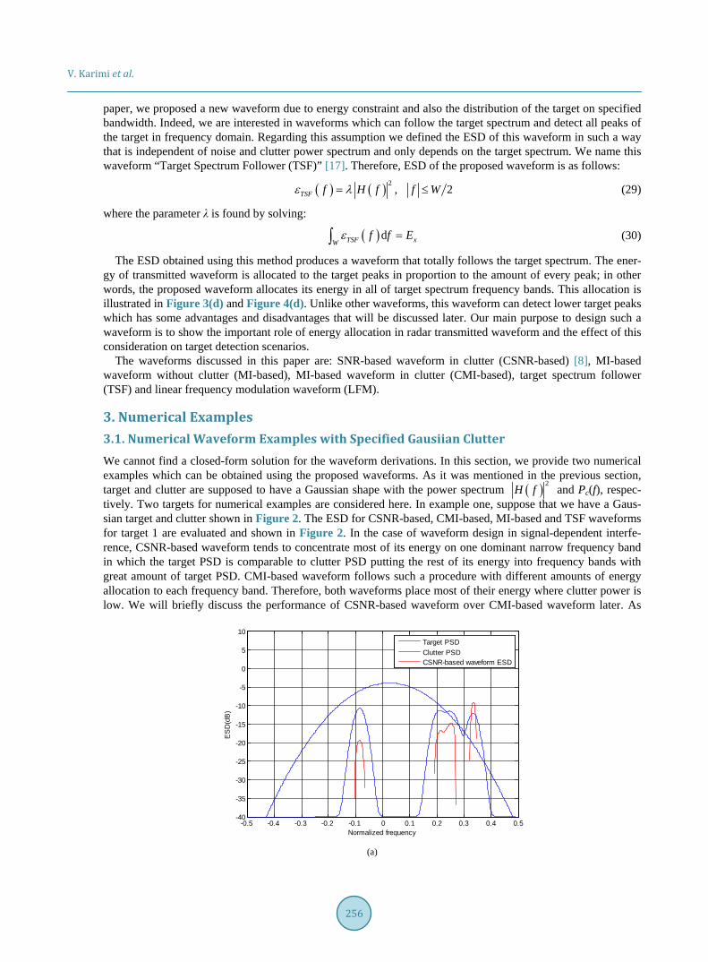
To evaluate the performance, we used receiver operating characteristic (ROC) curves corresponding to the obtained waveforms and LFM. Figure 5 shows these ROC curves for all scenarios. As it is clear, the improve-ment of obtaining waveforms over LFM is shown in this Figure for all scenarios; we see that CSNR-based and CMI-based waveforms for all scenarios have a better performance compared with other waveforms.
4. Providing General Result and Defining an Appropriate Closed-Loop Structure 4.1. Numerical Results with Different Deterministic Extended Target, Clutter and Noise Now to better demonstrate the importance of waveform design in cognitive radar, we simulate different targets, clutters and noise realizations. To reach an aggregation, we compute SNR and MI values for each waveform by changing TCR, TNR and CNR values in a specific range. For example in Figure 6(a) and Figure 6(b), SNR and MI changes in dB versus TCR for each waveform are illustrated. It can be concluded from this figure that all waveforms have a similar SNR performance with increasing TCR and as previously discussed have a better performance over LFM waveform.
From MI consideration, as we expected, CMI-based and MI-based have better performance with a little dif-ference compared with CSNR-based and TSF waveforms. Finally, we can conclude that indifferent values of TCR, all waveforms have 9 dB and 7 dB improvement in SNR and MI, respectively over LFM waveform.

V. Karimi et al.
263
Figure 6(c) and Figure 6(d) show the SNR and MI value changes in dB for different TNR values. As indi-cated in this Figure, CSNR-based and CMI-based waveforms are completely similar in low TNRs but in high TNR values in terms of MI, CMI-based waveform is slightly better. TSF waveform also shows a moderate per-formance and better than MI-based and LFM waveforms especially in moderate TNRs.
The last case shows the SNR and MI value changes in dB for different CNRs. As indicated in Figure 6(e) and Figure 6(f) for different values of CNRs, similar to those we have for TNR and TCR values, CSNR-based and CMI-based waveforms are completely similar. A noteworthy point is that in low CNR values, MI-based wave-form has a good performance but with increasing CNR, its performance declines and TSF waveform perfor-mance outperform this waveform in high CNR values. Finally, LFM waveform is fairly constant with CNR and performs the poorly as compared with other waveforms. So, according to the mentioned features for each wave-form and due to each application, we should propose a good structure which considers all aspects of the problem conditions. Due to each waveform feature, it should utilize the best waveform to transmit into the environment.
(a)
(b)
1e-9 1e-8 1e-7 1e-6 1e-5 1e-4 1e-3 1e-2 1e-1 1e00
0.1
0.2
0.3
0.4
0.5
0.6
0.7
0.8
0.9
1
Pfa
Pd
CSNR-basedMI-basedCMI-basedTSFLFM
1e-9 1e-8 1e-7 1e-6 1e-5 1e-4 1e-3 1e-2 1e-1 1e00
0.1
0.2
0.3
0.4
0.5
0.6
0.7
0.8
0.9
1
Pfa
Pd
CSNR-basedMI-basedCMI-basedTSFLFM
V. Karimi et al.
264
(c)
(d)
Figure 5. ROC curves corresponding to each waveform and each scenario. (a) Scenario 1. (b) Scenario 2. (c) Scenario 3. (d) Scenario 4.
Therefore, a cognitive radar should be designed in such a way that firstly evaluates the TCR, TNR and CNR values and considering to the application and also waveform features which are mainly discussed in this paper, chooses the best waveform to transmit into the environment and achieve the maximum probable values of PD.
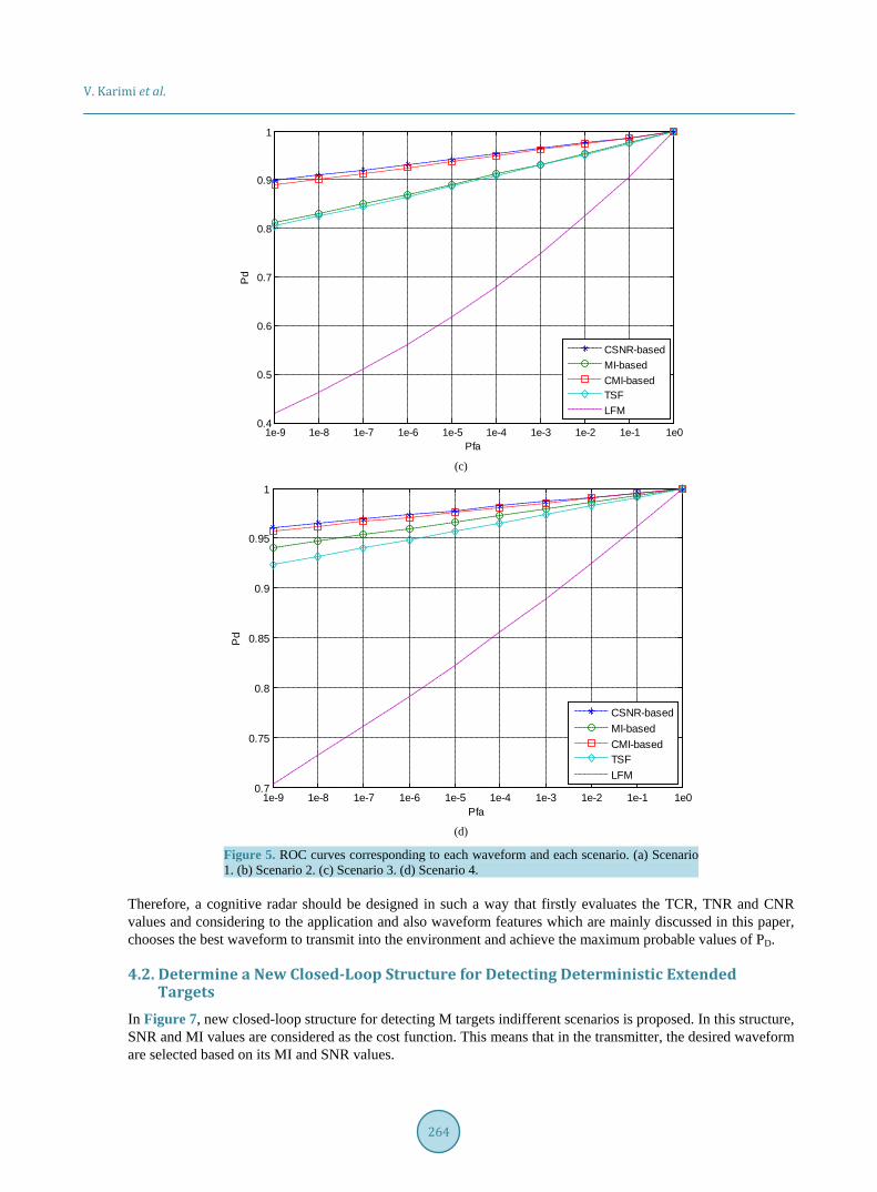
4.2. Determine a New Closed-Loop Structure for Detecting Deterministic Extended Targets
In Figure 7, new closed-loop structure for detecting M targets indifferent scenarios is proposed. In this structure, SNR and MI values are considered as the cost function. This means that in the transmitter, the desired waveform are selected based on its MI and SNR values.
1e-9 1e-8 1e-7 1e-6 1e-5 1e-4 1e-3 1e-2 1e-1 1e00.4
0.5
0.6
0.7
0.8
0.9
1
Pfa
Pd
CSNR-basedMI-basedCMI-basedTSFLFM
1e-9 1e-8 1e-7 1e-6 1e-5 1e-4 1e-3 1e-2 1e-1 1e00.7
0.75
0.8
0.85
0.9
0.95
1
Pfa
Pd
CSNR-basedMI-basedCMI-basedTSFLFM

V. Karimi et al.
265
(a)
(b)
(c)
-8 -5.5 -3 -0.5 216
20
24
28
32
36
40
TCR(dB)
SN
R(d
B)
CSNR-basedMI-basedCMI-basedTSFLFM
-8 -5.5 -3 -0.5 216
19
22
25
28
31
34
TCR(dB)
MI(d
B)
CSNR-basedMI-basedCMI-basedTSFLFM
-10 -5 0 5 100
5
10
15
20
25
30
TNR(dB)
SN
R(d
B)
CSNR-basedMI-basedCMI-basedTSFLFM

V. Karimi et al.
266
(d)
(e)
(e)
Figure 6. Comparison of SNR and MI versus TCR, TNR and CNR with deterministic extended target. (a) SNR versus TCR; (b) MI versus TCR; (c) SNR versus TNR; (d) MI versus TNR; (e) SNR versus CNR; (f) MI versus CNR.
-10 -5 0 5 100
5
10
15
20
25
30
TNR(dB)
MI(d
B)
CSNR-basedMI-basedCMI-basedTSFLFM
-5 -1 3 7 10.512
14
16
18
20
22
24
CNR(dB)
SN
R(d
B)
CSNR-basedMI-basedCMI-basedTSFLFM
-5 -1 3 7 10.512
14
16
18
20
22
24
CNR(dB)
MI(d
B)
CSNR-basedMI-basedCMI-basedTSFLFM
V. Karimi et al.
267
s(t)
Enviroment Match Filter
Enviroment Match Filter
r1(t)
rM(t)
z1(t)
zM(t)
.
.
.
.
.
.
.
.
.
Transmit desired waveform
RX: Multi Hypothesis Testing
ThTarget
detected
TX: Select desired waveform from waveform Data base based
on application
Yes
No
+r1(t)
hM(t) +
c(t)
n(t)
n(t)
.
.
....
h1(t)
c(t)
.
.
.
Th
ThTarget
Detected
rM(t)
Yes
Yes Target Detected
.
.
.
.
.
.
x1(t)
xM(t)
Feedback
Feedback
No
No
Figure 7. Modelling a new structure of cognitive radar for detecting targets in different noise and clutter scenarios.
As indicated in this figure, the proposed cognitive radar structure includes an adaptive transmitter based on
the feedback from the receiver and the interactions with a defined database. The radar transmitted its initial waveform into the environment. If the target is detected in the receiver, we have reached our goal; otherwise, cognitive radar loop is established using a feedback from the receiver to the transmitter and this procedure is done as long as the target of interest is identified. Surely, we can set the number of transmitting signals to a pre-determined value to prevent the cognitive radar from being in an infinitive loop.
5. Summaryand Conclusion In this paper, we considered a deterministic Gaussian extended target with Gaussian clutter case for our experi-ments. The transmitted waveform optimization is done by maximizing the signal to noise ratio and mutual in-formation between the target frequency responses of different targets and the received signal. This helps achieve a better performance in target recognition. We derived different MI-based, SNR-based and TSF waveforms and used an approximate analytical expression for the probability of detection for different waveforms and compared the performance of these waveforms based on this idea. The remarkable features for designing these waveforms for deterministic extended targets, are energy allocation in which waveforms should allocate their energy into frequency bands where target has the greatest PSD value and clutter has the smallest PSD value. This idea will cause the product of target and transmitted waveform got the maximum amount and then the performance of target detection in the presence of clutter will increase.
The derivations of MI-based waveforms for deterministic Gaussian extended targets and in the case of Gaus-sian clutter are new results. Moreover, TSF waveform in signal-dependent interference is a new result derived to show that depending on the application such as deterministic extended target, energy allocation is not done well. In fact for the scenarios outlined in the text, it is better to allocate most of transmitting waveform energy into frequency bands in which target has considerable peak amount and clutter amount is negligible instead of dis-tributing energy into all target spectrum peaks. In this paper, different values of SNR and MI are obtained in different TCR, CNR and TNR amounts and it is proven that the obtained waveforms have various performances in different TCR, CNR and TNR and in cognitive radar. We propose a new closed-loop structure considering all features discussed in this paper and for each scenario of target, clutter and noise intelligently find the optimum solution. This work just uses deterministic Gaussian targets case in Gaussian clutter. Future work will attempt to investigate methods of waveforms designing for stochastic extended targets in Gaussian and non-Gaussian en-vironments and suggest a general method for each clutter and target scenarios.

V. Karimi et al.
268
References [1] Haykin, S. (2006) Cognitive Radar: A Way of the Future. IEEE Signal Processing Magazine, 23, 30-40.
http://dx.doi.org/10.1109/MSP.2006.1593335 [2] Pillai, S.U., Oh, H.S., Youla, D.C. and Guerci, J.R. (2000) Optimum Transmit Receiver Design in the Presence of Sig-
nal-Dependent Interference and Channel Noise. IEEE Transactions on Information Theory, 46, 577-584. http://dx.doi.org/10.1109/18.825822
[3] Bell, M.R. (1993) Information Theory and Radar Waveform Design. IEEE Transactions on Information Theory, 39, 1578-1597. http://dx.doi.org/10.1109/18.259642
[4] Bell, M.R. (1988) Information Theory and Radar: Mutual Information and the Design and Analysis of Radar Wave-forms and Systems. Ph.D. Dissertation, California Institute of Technology, Pasadena.
[5] Kay, S. (2007) Optimal Signal Design for Detection of Gaussian Point Targets in Stationary Gaussian Clutter/Rever- beration. IEEE Journal of Selected Topics in Signal Processing, 1, 31-41.
[6] Garren, D.A., Osborn, M.K., Odom, A.C., Goldstein, J.S., Pillai, S.U. and Guerci, J.R. (2001) Enhanced Target Detec-tion and Identification via Optimized Radar Transmission Pulse Shape. IEE Proceedings—Radar, Sonar and Naviga-tion, 148, 130-138. http://dx.doi.org/10.1049/ip-rsn:20010324
[7] Romero, R. and Goodman, N. (2008) Information Theoretic Matched Waveform in Signal Dependent Interference. 2008 IEEE Radar Conference, Rome, 26-30 May 2008, 1-6. http://dx.doi.org/10.1109/RADAR.2008.4720730
[8] Deng, X., Qiu, C., Cao, Z., Morelande, M. and Moran, B. (2012) Waveform Design for Enhanced Detection of Ex-tended Target in Signal-Dependent Interference. IET Radar, Sonar & Navigation, 6, 30-38. http://dx.doi.org/10.1049/iet-rsn.2010.0275
[9] Jiu, B., Liu, H.W., Li, L.Y. and Wu, S.J. (2009) A Method of Waveform Design Based on Mutual Information. Fron-tiers of Electrical and Electronic Engineering in China, 4, 134-140. http://dx.doi.org/10.1007/s11460-009-0035-9
[10] Zhang, J.D., Zhu, D.Y. and Zhang, G. (2011) 5Multi-Objective Waveform Design for Cognitive Radar. Proceedings of 2011 IEEE CIE International Conference on Radar, Chengdu, 24-27 October 2011, 580-583. http://dx.doi.org/10.1109/cie-radar.2011.6159607
[11] Romero, R., Bae, J. and Goodman, N. (2011) Theory and Application of SNR and MI-Based Matched Illumination Waveforms. IEEE Transactions on Aerospace and Electronic Systems, 47, 912-927. http://dx.doi.org/10.1109/TAES.2011.5751234
[12] Romero, R.A. and Goodman, N.A. (2009) Waveform Design in Signal-Dependent Interference and Application to Target Recognition with Multiple Transmissions. IET Radar, Sonar & Navigation, 3, 328-340.
[13] Romero, R. and Goodman, N.A. (2009) Improved Waveform Design for Target Recognition with Multiple Transmis-sions. 2009 International Waveform Diversity and Design Conference, Kissimmee, 8-13 February 2009, 26-30.
[14] Bae, J. and Goodman, N. (2007) Adaptive Waveforms for Target Class Discrimination. 2007 International Waveform Diversity and Design Conference, Pisa, 4-8 June 2007, 395-399. http://dx.doi.org/10.1109/WDDC.2007.4339450
[15] Wang, B., Wang, J.K. and Song, X. (2012) A Novel Waveform Design Method Based on Mutual Information. 2012 International Conference on Environmental Engineering and Technology Advances in Biomedical Engineering, 8, 373.
[16] Wei, Y.M., Meng, H.D., Liu, Y.M. and Wang, X.Q. (2011) Radar Phase-Modulated Waveform Design for Extended Target Detection. Tsinghua Science & Technology, 16, 364-370. http://dx.doi.org/10.1016/S1007-0214(11)70053-0
[17] Karimi, V. and Norouzi, Y. (2013) Target Detection Enhancement Based on Waveform Design in Cognitive Radar. Electronics New Zealand Conference (ENZCon), Auckland, 5-6 December 2013, 40-45.
[18] Chen, C.-Y. and Vaidyanathan, P.P. (2009) MIMO Radar Waveform Optimization with Prior Information of the Ex-tended Target and Clutter. IEEE Transactions on Signal Processing, 57, 3533-3544. http://dx.doi.org/10.1109/TSP.2009.2021632