wave loads on ships and platforms under special and ... · fatigue life and capacity analysis of...
TRANSCRIPT
No. 1 • April • 2011
Norwegian Marine Technology Research Institute
ISSN 0801-1818
Con
ten
ts
MULDIF-2: A new multipurpose hydrodynamic analysis tool
Facing the need for a new generation of hydrodynamic analysis tools, MARINTEK is now developing a new code for future applications in offshore engineering. This is part of a long-term strategically planned effort based upon extensive funding from the Research Council of Norway, which is being carried out in order to establish basic tools for the future. Eventually, the new tool will also include ships with speed. Initially, , the focus is on stationary (moored) ships and plat-forms and fixed structures such as wind-turbine foundations in finite and shallow water. Deepwater floating wind turbines will also form part of the planned applications.
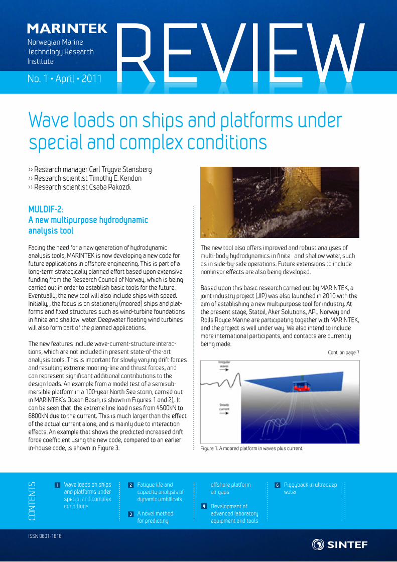
The new features include wave-current-structure interac-tions, which are not included in present state-of-the-art analysis tools. This is important for slowly varying drift forces and resulting extreme mooring-line and thrust forces, and can represent significant additional contributions to the design loads. An example from a model test of a semisub-mersible platform in a 100-year North Sea storm, carried out in MARINTEK’s Ocean Basin, is shown in Figures 1 and 2),. It can be seen that the extreme line load rises from 4500kN to 6800kN due to the current. This is much larger than the effect of the actual current alone, and is mainly due to interaction effects. An example that shows the predicted increased drift force coefficient using the new code, compared to an earlier in-house code, is shown in Figure 3.
The new tool also offers improved and robust analyses of multi-body hydrodynamics in finite and shallow water, such as in side-by-side operations. Future extensions to include nonlinear effects are also being developed.
Based upon this basic research carried out by MARINTEK, a joint industry project (JIP) was also launched in 2010 with the aim of establishing a new multipurpose tool for industry. At the present stage, Statoil, Aker Solutions, APL Norway and Rolls Royce Marine are participating together with MARINTEK, and the project is well under way. We also intend to include more international participants, and contacts are currently being made.
Wave loads on ships and platforms under special and complex conditions>> Research manager Carl Trygve Stansberg>> Research scientist Timothy E. Kendon>> Research scientist Csaba Pakozdi
Figure 1. A moored platform in waves plus current.
Cont. on page 7
Wave loads on ships and platforms under special and complex conditions
Fatigue life and capacity analysis of dynamic umbilicals
A novel method for predicting
offshore platform air gaps
Development of advanced laboratory equipment and tools
Piggyback in ultradeep water
1
4
2
3
6
REVIEW No. 1 • April • 2011
Dynamic umbilicals play an important role in many deepwater projects by providing the power supply for electrical units, chemical injection via tubes and fibre-optic data transimission. Due to the harsh environment and stingent performance requirements, it can be difficult to qualify the design of umbili-cal cross-sections to ensure sufficient operational margins for all phases of the life of the umbilical from installation to operation.
MARINTEK has recently verified two different umbilical cross-sections for Oceaneering Umbilical Solutions. These two umbilicals typify the main challenges for these structures.
The stress range caused by cyclic loading consists of a component related to the cyclic bending and another related
The air gap under offshore platform decks is an important design factor, and predicting the minimum air gap in harsh environments and the probability of wave crests impacting the underside of the deck is a challenging task.
The first application of the new method is TLPs (Tension Leg Platforms). The wave field under the platform deck is dis-turbed by the structure. Although the air gap under irregular wave conditions can be accurately determined through a well-designed model or CFD test, it is difficult to obtain reliable estimates for the extreme response. Due to nonlinear effects in steep sea states, data from many realizations of a given sea state are often required to obtain robust estimates. In many cases, therefore, only one or a few three-hour realiza-tions are simulated in the model basin.
There is thus a need to develop new methods to improve the estimates obtained from a limited data set.
MARINTEK has adopted a new approach, based on utilizing the ACER (Average Crossing Exceedance Rate) method that allows accurate prediction at extreme response levels. Model test results of the air gap underneath the deck of a TLP in
extreme random sea were used as case study data to bench-mark the statistical method.
A second application is jacket-type platforms. Unlike TLPs, jackets are relatively transparent to the waves, so that the wave field can be assumed to be undisturbed and therefore simulated numerically. The ACER method was applied to Monte Carlo-generated data.
A novel method for predicting offshore platform air gaps>> Research scientist Oleg Gaidai
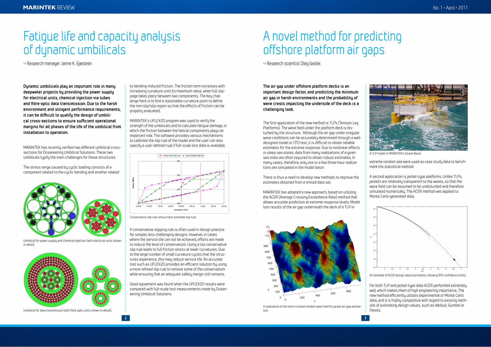
A realization of the short-crested random wave field for jacket air-gap estima-tion.
A TLP model in MARINTEK’s Ocean Basin.
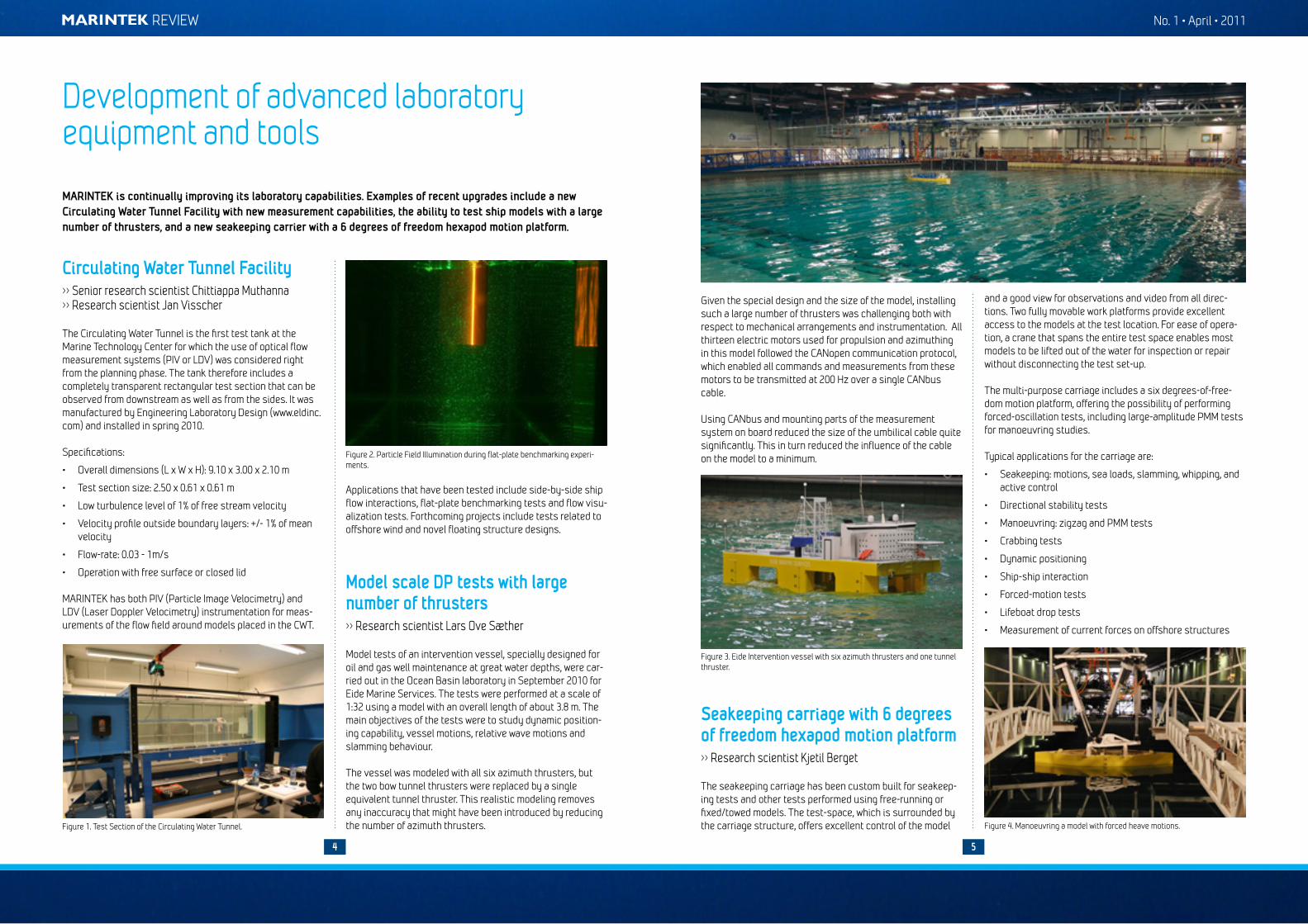
An example of ACER design value estimation, showing 95% confidence limits.
Fatigue life and capacity analysis of dynamic umbilicals>> Research manager Janne K. Gjøsteen
to bending-induced friction. The friction term increases with increasing curvature until its maximum value, when full slip-page takes place between two components. The key chal-lenge here is to find a reasonable curvature point to define the non-slip/slip region so that the effects of friction can be properly evaluated.
MARINTEK’s UFLEX2D program was used to verify the strength of the umbilicals and to calculate fatigue damage, in which the friction between the helical components plays an important role. The software provides various mechanisms to calibrate the slip rule of the model and the user can also specify a user-defined rule if full-scale test data is available.
A conservative slipping rule is often used in design practice for simpler, less challenging designs. However, in cases where the service life can not be achieved, efforts are made to reduce the level of conservatism. Using a too conservative slip rule leads to full friction stress at lower curvatures. Due to the large number of small curvature cycles that the struc-tures experience, this may reduce service life. An accurate tool such as UFLEX2D provides an efficient solution by using a more refined slip rule to remove some of the conservatism while ensuring that an adequate safety margin still remains.
Good agreement was found when the UFLEX2D results were compared with full-scale test measurements made by Ocean-eering Umbilical Solutions.
Umbilical for power supply and chemical injection (with electrical units shown in detail).
Umbilical for data transmission (with fibre optic units shown in detail).
Conservative slip rule versus best estimate slip rule.
2 3
For both TLP and jacket-type data ACER performed extremely well, which makes them of high engineering importance. The new method efficiently utilizes experimental or Monte Carlo data, and it is highly competitive with regard to existing meth-ods of estimating design values, such as Weibull, Gumbel or Pareto.
2 2.5 3 3.5 4 4.5 5 5.5 6 6.5 710
−8
10−7
10−6
10−5
10−4
10−3
10−2
10−1
η/σ
ν+ η
REVIEW No. 1 • April • 2011
4 5
Circulating Water Tunnel Facility>> Senior research scientist Chittiappa Muthanna>> Research scientist Jan Visscher
The Circulating Water Tunnel is the first test tank at the Marine Technology Center for which the use of optical flow measurement systems (PIV or LDV) was considered right from the planning phase. The tank therefore includes a completely transparent rectangular test section that can be observed from downstream as well as from the sides. It was manufactured by Engineering Laboratory Design (www.eldinc.com) and installed in spring 2010.
Specifications:
• Overall dimensions (L x W x H): 9.10 x 3.00 x 2.10 m
• Test section size: 2.50 x 0.61 x 0.61 m
• Low turbulence level of 1% of free stream velocity
• Velocity profile outside boundary layers: +/- 1% of mean velocity
• Flow-rate: 0.03 - 1m/s
• Operation with free surface or closed lid
MARINTEK has both PIV (Particle Image Velocimetry) and LDV (Laser Doppler Velocimetry) instrumentation for meas-urements of the flow field around models placed in the CWT.
Applications that have been tested include side-by-side ship flow interactions, flat-plate benchmarking tests and flow visu-alization tests. Forthcoming projects include tests related to offshore wind and novel floating structure designs.
Model scale DP tests with large number of thrusters>> Research scientist Lars Ove Sæther
Model tests of an intervention vessel, specially designed for oil and gas well maintenance at great water depths, were car-ried out in the Ocean Basin laboratory in September 2010 for Eide Marine Services. The tests were performed at a scale of 1:32 using a model with an overall length of about 3.8 m. The main objectives of the tests were to study dynamic position-ing capability, vessel motions, relative wave motions and slamming behaviour.
The vessel was modeled with all six azimuth thrusters, but the two bow tunnel thrusters were replaced by a single equivalent tunnel thruster. This realistic modeling removes any inaccuracy that might have been introduced by reducing the number of azimuth thrusters.
Given the special design and the size of the model, installing such a large number of thrusters was challenging both with respect to mechanical arrangements and instrumentation. All thirteen electric motors used for propulsion and azimuthing in this model followed the CANopen communication protocol, which enabled all commands and measurements from these motors to be transmitted at 200 Hz over a single CANbus cable.
Using CANbus and mounting parts of the measurement system on board reduced the size of the umbilical cable quite significantly. This in turn reduced the influence of the cable on the model to a minimum.
Seakeeping carriage with 6 degrees of freedom hexapod motion platform>> Research scientist Kjetil Berget
The seakeeping carriage has been custom built for seakeep-ing tests and other tests performed using free-running or fixed/towed models. The test-space, which is surrounded by the carriage structure, offers excellent control of the model
Development of advanced laboratory equipment and tools
Figure 1. Test Section of the Circulating Water Tunnel.
MARINTEK is continually improving its laboratory capabilities. Examples of recent upgrades include a new Circulating Water Tunnel Facility with new measurement capabilities, the ability to test ship models with a large number of thrusters, and a new seakeeping carrier with a 6 degrees of freedom hexapod motion platform.
Figure 2. Particle Field Illumination during flat-plate benchmarking experi-ments.
and a good view for observations and video from all direc-tions. Two fully movable work platforms provide excellent access to the models at the test location. For ease of opera-tion, a crane that spans the entire test space enables most models to be lifted out of the water for inspection or repair without disconnecting the test set-up.
The multi-purpose carriage includes a six degrees-of-free-dom motion platform, offering the possibility of performing forced-oscillation tests, including large-amplitude PMM tests for manoeuvring studies.
Typical applications for the carriage are:
• Seakeeping: motions, sea loads, slamming, whipping, and active control
• Directional stability tests
• Manoeuvring: zigzag and PMM tests
• Crabbing tests
• Dynamic positioning
• Ship-ship interaction
• Forced-motion tests
• Lifeboat drop tests
• Measurement of current forces on offshore structures
Figure 3. Eide Intervention vessel with six azimuth thrusters and one tunnel thruster.
Figure 4. Manoeuvring a model with forced heave motions.

REVIEW No. 1 • April • 2011
6 7
The compressive strain in the sag-bend of the pipe is the governing parameter in determining how low lay tensions that can be applied. Installing the pipe with a low lay tension offers many benefits. Smaller curve radii can be obtained, while the severity of free spans is reduced as the pipe will follow the seabed topography more closely. It has been shown that very low lay tensions may be obtained without threatening the integrity of the pipe. Pipes may also be laid along curves with relatively small radii.
The local sag-bend pipe curvature is governed by the top ten-sion, while current direction and the radius of the route have much smaller impacts.
The highest utilized capacity was the local curvature of the DEH cable (Figure 2). We found that doubling the strap dis-tance in piggyback layout increased the local deflections of the cable between two straps, more than halving the maxi-mum cable curvature.
Piggyback in ultradeep water>> Research scientist Joakim Taby>> Research scientist Mateusz.Graczyk
0 500 1000 1500 2000 2500 3000 3500 4000 4500 50000
0.1
0.2
0.3
0.4
0.5
0.6
0.7Normalized cable curvatures
Nor
mal
ized
cab
le c
urva
ture
s [-]
Curvilinear coordinate [m]
Base case strap distanceDouble strap distance
Figure 2. DEH cable curvature normalised with respect to capacity.
Figure 3. Top view of the piggyback layout between two straps, with the DEH cable buckling in the sag-bend area.
Wave loads on ships and ..., cont from page 1
0
1000
2000
3000
4000
5000
6000
7000
0 500 1000 1500 2000 2500 3000 3500
T1 [k
N]
time t [s]
MOORING LINE FORCE IN LINE 1
WAVES + CURRENT WAVES ONLY
Figure 2. Dynamic line tension time series from a model test in a 100-year storm with Hs=14.7m. Black line: Waves only. Light red line: Waves plus 1.05m/s current.
Figure 3. Normalized wave drift force coefficients on a hemisphere in waves only and in waves plus current (two current speeds). Fn (Froude number)= normalised current; kR= normalised wave number.
Wave impact loads on vertical columns – CFD analysis
Due to its importance for the design and limit-state analysis of column-based offshore platforms such as semisubmersibles and gravity-based structures, the prediction of extreme wave impact loads on the columns of offshore structures has been a high-priority field of research for many years. In deep water, much of this research has historically focused on non-break-ing waves. However, it is known that breaking waves (which are a result of crest height exceeding a limiting steepness) exert
far larger local forces on the columns of offshore structures than non-breaking waves. Although a significant body of experimental and theoretical work exists on breaking waves, - work that has led to a good understanding of this phenomenon - the complex physics and its impact on structures in deep water are still poorly understood. Satisfactory theoretical tools for robust prediction in design are therefore still under devel-opment, and experimental knowledge is important input.
To investigate this problem, one of the sub-tasks of MARINTEK’s Wave Impact Loads JIP focused on an ideal-ised test setup of a fixed rectangular column in deep-water breaking waves. An experimental study in a wave tank was performed in Phase 1 (2007-2008), while in the recent Phase 2 (2009-2010) the same set-up has been studied and recon-structed by means of CFD, primarily in order to assess the feasibility of performing numerical reconstructions of such events. Three-dimensional simulations were carried out using the CFD tool Star-CCM+ V5.03.0056 (CD-adapco.com). Results were simulated in model scale (1:40) for easy comparison with the model tests. A special challenge is to become able to establish a numerical wave tank for generating and recon-structing the breaking wave itself in a satisfactory way, and a procedure to overcome this was established.
The results show that CFD modelling can be a valuable tool to provide qualitative insights into the physics of wave impacts in space and time. Such insights could facilitate the develop-ment of simpler engineering procedures for breaking wave
As we move into deeper waters new challenges related to pipeline installation can emerge. For instance currents become a more dominant environ-mental load compared to wave loads and first-order vessel motions. In order to assess the layability of a flowline in ultradeep water (3000 metres), various pipeline concepts have been evaluated for Statoil. One of these was a piggyback solution with a 6” pipe and a 2.5” direct electrical heating (DEH) cable.
SIMLA - a tailor-made finite element program for engineering analysis of offshore pipelines during design, installation and operation - was utilised in this study.
Numeric route with KP-values KP-value for TDP
DEPANG
new configuration
Figure 1. Sketch of the simulated J-lay installation
J-lay installation as illustrated in Figure 1 was simulated along both a straight route and various curvatures. The “screening” approach we employed may be regarded as a repeated sequence of static solutions, in which the pipe configuration is stepped along a planned numerical route, as opposed to the “feed” approach, in which new elements are introduced into the catenary on the lay vessel.
In the piggyback model the pipe and the cable are strapped together. In order to assess the effect of the asymmetrical cross section of the piggyback solution, direction-dependant drag coefficients were introduced.
The following strength criteria were evaluated: allowable ten-sion, maximum curvature and tensile/compressive strain for the DEH cable, and maximum sag-bend strain and axial force capacity for the pipe. In order to determine the effect of the DEH cable on layability, identical cases were simulated for the single pipe and the piggyback layout: lay tension in the range 50-100kN, curved routes with radii in the range 500-2000m, and various current directions and profiles.
We found that laying the pipe to depths of down to 3000 metres did not involve any significant challenges with respect to the integrity of the pipe. As far as the DEH cable is concerned, the external pressure appears to be the greatest challenge.
A certain amount of cable curvature could be observed on the seabed. This was caused by pipe compression (due to external pressure) and resulting in cable buckling (Figure 3). In the sag-bend area the curvature is larger due to both pipe compression and the cable lying on the inner side of the pipe curvature. The curvature decreases towards the top, due to decreased pipe compression resulting from smaller external pressure. Cont. on page 8

NORWEGIAN MARINE TECHNOLOGY RESEARCH INSTITUTE
Otto Nielsens veg 10, P.O.Box 4125 Valentinlyst NO-7450 Trondheim, Norway
Phone: +47 7359 5500 Fax: +47 7359 5776E-mail: [email protected] www.marintek.no
Norwegian Marine Technology Research Institute
AuthorsCarl Trygve StansbergResearch manager
Phone: +47 932 68 363E-mail: CarlTrygve.Stansberg @marintek.sintef.no
impact loads as are employed, for example, in coastal engi-neering. The resulting breaking wave characteristics compare fairly well to measurements. Initial comparisons suggest that the resulting impact loads also show rough similarities to model test results, although the results are quite sensitive to critical simulation parameters. Accurate load predictions are still quite demanding and further studies and improvements
Figure 5. 3D surface simulation, same event as in Figure 1 (seen from another perspective).
Figure 4. Breaking wave with particle velocity shown at two instants when hitting column. CFD simulation, model scale results.
are recommended. The CFD study will be presented at OMAE 2011 (paper 49976). Some plots from the CFD analysis are shown in Figures 4 and 5.
Participants in the MARINTEK Wave Impact Loads JIP – Phase 2 include ABS, Aker Solutions, ConocoPhillips, MARINTEK, Petrobras and Statoil.
Wave loads on ships and ..., cont from page 7
Janne K. Ø. GjøsteenResearch manager
Phone: +47 73 59 59 88E-mail: JanneKristin.Gjosteen @marintek.sintef.no
Chittiappa MuthannaSenior research scientist
Phone: +47 938 63 824E-mail: [email protected]
Oleg GaidaiResearch scientist
Phone: +47 478 24 834 E-mail: [email protected]
Jan VisscherResearch scientist
Phone: +47 484 24 320
E-mail: [email protected]
Mateusz GraczykResearch scientist
Phone: +47 936 27 614
E-mail: [email protected]
Lars O. SætherResearch scientist
Phone: +47 976 54 258
E-mail: [email protected]
Kjetil BergetResearch scientist
Phone: +47 997 30 648
E-mail: [email protected]
Joakim TabyResearch scientist
Phone: +47 993 08 188
E-mail: [email protected]