watts pneumatic / electric actuation and controlsmedia.wattswater.com/f-p-e-ac.pdf · 5 pneumatic...
TRANSCRIPT

WattsPneumatic / Electric
Actuation and Controls
F-P/E-AC

2
Table of Contents
PA/PAS SeriesPneumatic Actuators - Features . . . . . . . . . . . . . . . . . . . . . . . . . . . . . . . . . . . . . . .3Modes of Operation . . . . . . . . . . . . . . . . . . . . . . . . . . . . . . . . . . . . . . . . . . . . . . . .4
Double Acting PASpring Return PAS
Pneumatic Actuator Sizing Instructions . . . . . . . . . . . . . . . . . . . . . . . . . . . . . . . . . .5Options and Accessories . . . . . . . . . . . . . . . . . . . . . . . . . . . . . . . . . . . . . . . . . . . .6Suggested Specifications . . . . . . . . . . . . . . . . . . . . . . . . . . . . . . . . . . . . . . . . . . . .7Engineering & Performance Data . . . . . . . . . . . . . . . . . . . . . . . . . . . . . . . . . . . . . .8PAS Torque Data . . . . . . . . . . . . . . . . . . . . . . . . . . . . . . . . . . . . . . . . . . . . . . . . . . .9Materials of Construction . . . . . . . . . . . . . . . . . . . . . . . . . . . . . . . . . . . . . . . . . . .10Dimensions . . . . . . . . . . . . . . . . . . . . . . . . . . . . . . . . . . . . . . . . . . . . . . . . . . . . . .11
PF SeriesPower-Flex Electric Actuator - Features . . . . . . . . . . . . . . . . . . . . . . . . . . . . . . . .12Design Features . . . . . . . . . . . . . . . . . . . . . . . . . . . . . . . . . . . . . . . . . . . . . . . . . .13Options and Controls . . . . . . . . . . . . . . . . . . . . . . . . . . . . . . . . . . . . . . . . . . . . . .14Specifications . . . . . . . . . . . . . . . . . . . . . . . . . . . . . . . . . . . . . . . . . . . . . . . . . . . .15Engineering Data . . . . . . . . . . . . . . . . . . . . . . . . . . . . . . . . . . . . . . . . . . . . . . . . . .15Materials of Construction . . . . . . . . . . . . . . . . . . . . . . . . . . . . . . . . . . . . . . . . . . .16Dimensions . . . . . . . . . . . . . . . . . . . . . . . . . . . . . . . . . . . . . . . . . . . . . . . . . . . . . .17Standard Actuator Wiring Diagram . . . . . . . . . . . . . . . . . . . . . . . . . . . . . . . . . . . .18
LVW SeriesElectric Actuators - Features . . . . . . . . . . . . . . . . . . . . . . . . . . . . . . . . . . . . . . . . .19Specifications . . . . . . . . . . . . . . . . . . . . . . . . . . . . . . . . . . . . . . . . . . . . . . . . .20-21Dimensions . . . . . . . . . . . . . . . . . . . . . . . . . . . . . . . . . . . . . . . . . . . . . . . . . . . . . .21Spare Parts and Option Kits . . . . . . . . . . . . . . . . . . . . . . . . . . . . . . . . . . . . . . . . .22Wiring Diagrams . . . . . . . . . . . . . . . . . . . . . . . . . . . . . . . . . . . . . . . . . . . . . . . . . .23Suggested Specifications . . . . . . . . . . . . . . . . . . . . . . . . . . . . . . . . . . . . . . . . . . .24
EA 350Unidirectional Electric Actuator - Features . . . . . . . . . . . . . . . . . . . . . . . . . . . . . .25Terminal Functions . . . . . . . . . . . . . . . . . . . . . . . . . . . . . . . . . . . . . . . . . . . . . . . .25Specifications . . . . . . . . . . . . . . . . . . . . . . . . . . . . . . . . . . . . . . . . . . . . . . . . . . . .26Dimensions . . . . . . . . . . . . . . . . . . . . . . . . . . . . . . . . . . . . . . . . . . . . . . . . . . . . . .26Valve Actuation Data Sheet . . . . . . . . . . . . . . . . . . . . . . . . . . .27
Agent Listing . . . . . . . . . . . . . . . . . . . . . . . . . . . . . . . . . . . . . . . . . . . .28

3
Features Benefits• Epoxy coated, anodized aluminum extruded body • Corrosion resistant
• One piece shaft • Blow-out proof
• Internally loaded full tooth engagement • Length of piston, self-contained
• Standard end caps for PA & PAS • Modular design, simple conversion
• Position indicator • High visibility position
• IS0 /Namur mounting • Universal adaptability
• Top & bottom non-metallic shaft bearings • Side load support, minimum dynamic seal wear
• Rolled threads • 30% higher retaining capacity
• Permanently lubricated assembly • Maintenance free
• Travel stops • Open & closed adjustment
• Dual mounting pads • Ease of accessory mounting
• 4 dynamic seals • Low coefficient of friction surfaces
• 4 static seals • No pinion seal wear
• Manual override • Emergency override on air failure
• Internal ports • No external tubing
• Female drive • Low profile direct mounting
• All stainless steel fasteners • Maximum corrosion protection
Pneumatic ActuatorsPA / PAS Series
Pneumatic Double Rack and Pinion ActuatorsDouble Acting and Spring Return(180 to 7000 in./lbs. Torque Output @ 80 psig)
Watts designed Series PA and PAS pneumatic actuators tomeet end-user requirements. From the design stage, the con-cept of extended service life with virtually no maintenance hasbeen paramount with maximum torque output per dollar andreduction of overall profile as key design considerations.
The double acting version (PA) and spring return version (PAS)fully comply with the original design concepts. The anodizedaluminum body and end caps and die cast aluminum pistons protect against prematurefailure due to corrosion and provide superior wear resistance. Using special die castingmethods, pistons are produced with maximum density and wear resistance at the gear toothlocation.
With special consideration toward safety, Watts revolutionizes rack and pinion actuatordesign with an internally loaded output shaft that cannot be removed. Additionally, PAunits can be converted to PAS units simply by adding appropriate springs providing flex-ibility and simple inventories.
All pinions are supported with non-metallic, non-corrosive, upper and lower bushingscontaining a dynamic seal. Dynamic pinion seals do not come in direct contact with theactuator body.
Extended life, contemporary design, safety, simplicity, and lower inventory levels combine to make Watts PA/PAS Seriesactuators the logical choice for quarter-turn pneumatic actuation requirements.
Dynamic SealStatic Seal
Acetal Bearing

4
Modes of Operation
Double Acting PA
Figure 1Air is supplied to Port A, pressurizing the inside chamber,forcing the pistons outward resulting in a counter-clock-wise rotation of the piston shaft. The air in the outsidechambers is vented through Port B.
Figure 2Air is supplied to Port B, pressurizing the outside cham-bers, forcing the pistons inward resulting in a clockwiserotation of the piston shaft. The air in the inside chamberis vented through Port A.
Figure 3Air is supplied to Port A, pressurizing the inside chamber,forcing the pistons outward, compressing the springs thatare located in the outside chambers, resulting in a count-er-clockwise rotation of the piston shaft. Any air that is inthe outside chambers is vented through Port B.
Figure 4With loss of air pressure to the actuator, the pistons areforced inward by the energy of the compressed springs,resulting in a clockwise rotation of the piston shaft. Any airthat is in the inside chamber is vented through Port A.
Air to Port “A”
Port “A”No Air PressureAir to Port “A”
Air to Port “B”
Spring Return PAS
5
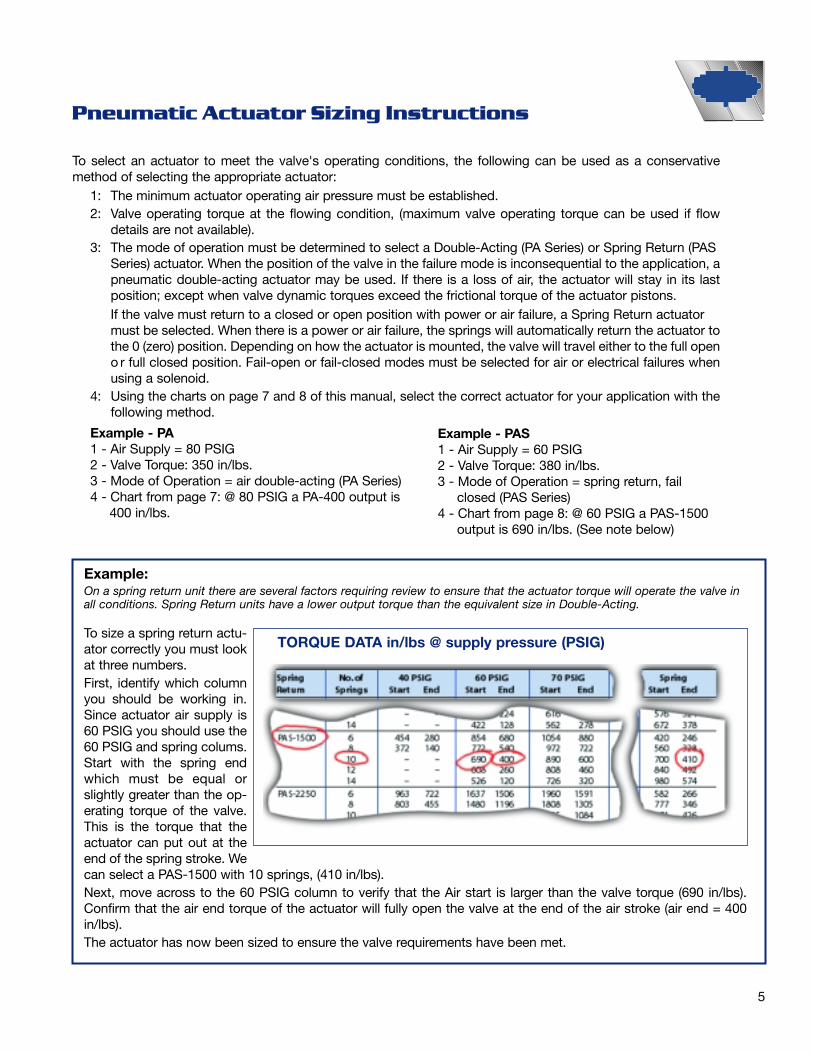
Pneumatic Actuator Sizing Instructions
To select an actuator to meet the valve's operating conditions, the following can be used as a conservativemethod of selecting the appropriate actuator:
1: The minimum actuator operating air pressure must be established. 2: Valve operating torque at the flowing condition, (maximum valve operating torque can be used if flow
details are not available).3: The mode of operation must be determined to select a Double-Acting (PA Series) or Spring Return (PAS
Series) actuator. When the position of the valve in the failure mode is inconsequential to the application, a pneumatic double-acting actuator may be used. If there is a loss of air, the actuator will stay in its lastposition; except when valve dynamic torques exceed the frictional torque of the actuator pistons.If the valve must return to a closed or open position with power or air failure, a Spring Return actuator must be selected. When there is a power or air failure, the springs will automatically return the actuator tothe 0 (zero) position. Depending on how the actuator is mounted, the valve will travel either to the full openo r full closed position. Fail-open or fail-closed modes must be selected for air or electrical failures when using a solenoid.
4: Using the charts on page 7 and 8 of this manual, select the correct actuator for your application with thefollowing method.
Example - PA1 - Air Supply = 80 PSIG2 - Valve Torque: 350 in/lbs.3 - Mode of Operation = air double-acting (PA Series)4 - Chart from page 7: @ 80 PSIG a PA-400 output is
400 in/lbs.
To size a spring return actu-ator correctly you must lookat three numbers. First, identify which columnyou should be working in.Since actuator air supply is60 PSIG you should use the60 PSIG and spring colums.Start with the spring endwhich must be equal orslightly greater than the op-erating torque of the valve.This is the torque that theactuator can put out at theend of the spring stroke. Wecan select a PAS-1500 with 10 springs, (410 in/lbs).Next, move across to the 60 PSIG column to verify that the Air start is larger than the valve torque (690 in/lbs).Confirm that the air end torque of the actuator will fully open the valve at the end of the air stroke (air end = 400in/lbs). The actuator has now been sized to ensure the valve requirements have been met.
Example:On a spring return unit there are several factors requiring review to ensure that the actuator torque will operate the valve inall conditions. Spring Return units have a lower output torque than the equivalent size in Double-Acting.
TORQUE DATA in/lbs @ supply pressure (PSIG)
Example - PAS1 - Air Supply = 60 PSIG2 - Valve Torque: 380 in/lbs.3 - Mode of Operation = spring return, fail
closed (PAS Series)4 - Chart from page 8: @ 60 PSIG a PAS-1500
output is 690 in/lbs. (See note below)

6
PA/PAS Series Options and Accessories
PositionersFor control applications, WATTS offers a complete line ofpneumatic rotary positioners for input signals of 3-15(std.), 6-30, 3-9 and 9-15 psi; and electro-pneumaticpositioners for input signals of 4-20 mA (std.), or 0-20 mA.
DIRECT MOUNT POSITIONER SERIES PW-496
Top mounted, rotary limit switchesWatts offers both mechanical and proximity type limit switches for thePA/PAS Series Pneumatic Actuators. Each limit switch comes com-plete with all the hardware necessary for quick and easy mounting.Standard features of our switches include NEMA IV rating (NEMA VII,IX optional), various switch complements and position indicators.
Solenoid ValvesWatts solenoid valve features includebalanced spool construction that allowsports to be plugged for 2 or 3-way oper-ation, coil hermetically sealed and guar-anteed for life against burnout, manualoverride aids in machine set-up, NemaIV (Std), VII and IX configurations, UL andCSA recognized, and mounts directly toPA/PAS housing without tubing.
Other Options and Accessories:• Speed Controls • Special Coatings • Filter/Regulators • Feedback Options (Potentiometers)
Consult Watts for additional information on optional accessories.
ACTUATOR WITH ISO-MOUNTED POSITIONER

7
PA / PAS Suggested Specifications
GeneralThe actuator shall be pneumatically operated, travelling aminimum of 90º in each direction and be able to overtrav-el at 11⁄2º more in each direction. The actuator shall betotally enclosed without external moving parts. All pneu-matic passageways must be integral to the actuator hous-ing eliminating the need for external tubing. Actuatorsshall be of rack and pinion design with output torque lin-ear throughout travel. Actuator shall be provided with 2piston guide rings to extend actuator life and reduce fric-tion. Actuator must be supplied with travel adjustmentsand a mechanical visual position indicator that can beeasily removed to expose the output shaft to manuallyoverride the actuator. The output pinion must be electro-less nickel plated for corrosion protection. Actuators shallbe capable of all mounting orientations.All actuator housings shall be of hard anodized aluminumwith external fasteners made of stainless steel. Springsshall be spring steel, zinc-plated for corrosion protection.All seals shall be of BUNA-N (nitrile) and shaft bearings ofacetal resin.The actuator shall be factory lubricated and require noadditional lubrication and shall be factory tested to ensureminimum torque.Spring Return - Modular DesignThe Spring Return System for failsafe applications mustbe installed in the same housing and end caps as the dou-ble acting actuator. The use of extended bolts shall beused so that the spring torque can be safely released priorto the end cap being removed.Standard Materials shall beBody: Epoxy coated, Anodized aluminum alloy,
Type 1End Caps: Epoxy coated, die-cast aluminum alloyOutput Shaft: Carbon Steel, ENP CoatedPiston Bearings: TeflonShaft Bearings: AcetalFasteners: Stainless SteelSprings: Zinc-plated, Spring Steel O-Rings Seals: BUNA-N
Service DataActuators shall be designed for pneumatic operation up toa maximum pressure of 120 PSIG (8.6 bars) and for tem-perature ranges of - 4ºF (-20ºC) to 180ºF (85ºC). Filteredair is recommended but not required. The units shall beable to operate with other media such as hydraulic oil orwater. All double acting and spring return units shall besuitable for both on/off and throttling applications.Standard one year warranty.
Optional EquipmentSolenoidsSolenoid control module for electrical operation of actua-tor on/off requirements. The solenoid shall be supplied inNEMA IV waterproof and NEMA VII explosion-proofenclosures. Solenoid shall be provided with manual over-ride built into the body. Solenoid shall have a 1⁄4“ NPTpneumatic port and a 1⁄2" NPT electrical connection andoperate at 115 Volts AC, 50/60 HZ. Two-way speed con-trols shall be provided as options and shall be adjustablein each direction of actuator travel.
Limit SwitchesLimit Switch Control Module for electrical signal indicationof actuator and valve position. The limit switch shall bemounted directly to the top of the actuator. The housingshall be NEMA IV waterproof or NEMA VII explosion-proofconstruction with two S.P.D.T. switches with two sepa-rately adjustable cams that can be adjustable through 90ºof travel. The switch must be rated at 15 amps for 115 or230 Volts A.C. Additional switches can be added whenspecified. The switches must be pre-wired to a terminalstrip that is built into the switch housing. The conduit entryshall be minimum 1⁄2" NPT.
Positioner PW496Pneumatic Positioner Module for Control Valve Services.The standard positioner input signal shall be 3-15 PSIG (4-20mA optional), suitable for both double-acting andspring return actuator requirements. Positioner shall besuitable for direct and reverse acting operation and splitrange applications. The positioner shall operate with amaximum air supply of 120 PSIG and a maximum air con-sumption not to exceed 0.28 Standard Cubic Feet perMinute (SCFM) in a balanced condition with 87 PSIG airsupply pressure. Positioner Linearity 0.7%, Dead ban0.8%, Repeatability 0.5%. Positioner shall direct mount tothe top of the actuator housing.
MILITARY SPECIFICATION ANODIC COATINGS FOR ALUMINUM AND ALUMINUM ALLOYS:The PA/PAS epoxy coated, anodized aluminum alloy, Type 1 body meets the specification for use by allDepartments and Agencies of the Department of Defense.Type 1 - Chromic acid anodizing, conventional coatings produced from chromic acid bath. (see 3.4.1)
88
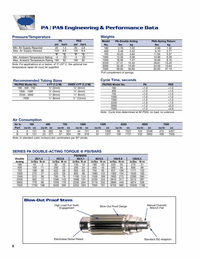
PA / PAS Engineering & Performance Data
Blow-Out Proof StemHigh Load Full Tooth
EngagementBlow-Out Proof Design
Standard ISO AdaptionElectroless Nickel Plated
PSI/BARSDouble 20/1.4 40/2.8 60/4.1 80/5.5 100/6.9 120/8.3Acting in/lbs N-m in/lbs N-m in/lbs N-m in/lbs N-m in/lbs N-m in/lbs N-m
180 45 5 90 10 135 15 180 20 225 25 270 31400 100 11 200 23 300 34 400 45 500 56 600 68750 188 36 422 48 563 64 750 85 937 106 1171 1321000 270 27 520 59 800 90 1080 122 1360 154 1640 1851500 375 36 700 79 1100 124 1500 169 1900 215 2300 2602250 563 72 1266 143 1688 191 2250 254 2810 317 3513 3973000 779 88 1558 176 2338 264 3116 352 3896 440 4674 5287000 1750 198 3500 395 5250 593 7000 791 8750 989 10500 1186
SERIES PA DOUBLE-ACTING TORQUE @ PSI/BARS
Recommended Tubing SizesPA/PAS Model No. 4 FT (1.2 M) OVER 4 FT (1.2 M)
180 , 400 , 750 1⁄8" (3mm) 1⁄8" (3mm)1000 , 1500 1⁄8" (3mm) 1⁄8" (3mm)2250 , 3000 1⁄4" (6mm) 1⁄4" (6mm)
7000 1⁄4" (6mm) 1⁄2" (12mm)
Cycle Time, secondsPA/PAS Model No. PA PAS
180 <1.0 <1.0400 <1.0 <1.0750 <1.0 <1.01000 <1.0 <1.01500 <1.0 <1.02250 <1.0 <1.03000 <1.0 <2.07000 <1.0 <4.0
Note: Cycle time determined at 80 PSIG, no load, no solenoid.
Pressure/TemperaturePA PAS
psi bars psi barsMin. Air Supply Required 20 1.4 40 2.8Max. Air Supply Allowed 120 8.6 120 8.6
ºF ºC ºF ºCMin. Ambient Temperature Rating -4 -20 -4 -20Max. Ambient Temperature Rating 180 82 180 82
Note: For applications at or below -4º F/-20º C, the optional lowtemperature repair kit must be supplied.
Air to 180 400 750 1000 1500 2250 3000 7000Port cu-in cc cu-in cc cu-in cc cu-in cc cu-in cc cu-in cc cu-in cc cu-in cc
A 8 131 16 262 34 557 44 721 61 1000 95 1557 125 2048 272 4457B 8 131 23 377 57 934 56 918 81 1327 106 1737 232 3802 458 7505
Note: In standard cubic inches/cubic centimeters per 90º stroke.
WeightsModel PA–Double Acting PAS–Spring Return
No. lbs. kg lbs. kg180 2.70 1.22 2.90 1.32400 5.40 2.45 6.10 2.77750 10.23 4.64 11.84 5.37
1000 12.30 5.58 13.90 6.301500 16.00 7.27 18.00 8.162250 27.41 12.43 29.61 13.433000 32.30 14.65 34.50 15.647000 68.00 30.84 82.00 37.19
*Full complement of springs.
Air Consumption
Manual OverrideWrench Flat
9
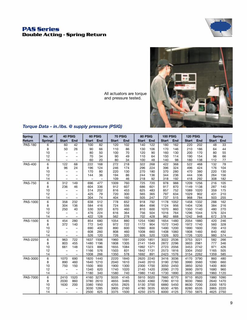
PAS Series Double Acting - Spring Return
Spring No. of 40 PSIG 60 PSIG 70 PSIG 80 PSIG 100 PSIG 120 PSIG SpringReturn Springs Start End Start End Start End Start End Start End Start End Start EndPAS-180 6 60 42 100 82 120 102 140 122 180 162 220 202 48 33
8 50 26 90 66 110 86 130 106 170 146 210 186 64 4410 – – 80 50 100 70 120 90 160 130 200 170 80 5512 – – 70 34 90 49 110 64 150 114 190 154 96 6614 – – 60 20 80 34 100 48 140 98 180 138 112 77
PAS-400 6 122 68 222 168 272 218 322 268 422 368 522 468 132 788 96 24 196 124 246 174 296 224 396 324 496 424 176 10410 – – 170 80 220 130 270 180 370 280 470 380 220 13012 – – 144 36 194 86 244 136 344 236 444 336 264 15614 – – – – 109 46 218 92 318 192 418 292 308 182
PAS-750 6 312 149 696 477 1009 760 725 720 978 988 1209 1256 216 1058 236 46 604 336 912 607 686 601 917 870 1149 1138 287 14010 – – 514 202 816 453 625 483 857 752 1089 1020 359 17512 – – 425 79 720 300 565 365 797 634 1029 902 431 21014 – – 304 74 404 160 505 247 737 515 968 784 503 255
PAS-1000 6 358 232 638 512 778 652 918 792 1178 1052 1458 1332 288 1628 304 136 584 416 724 556 864 696 1124 956 1404 1236 384 21610 250 40 530 320 670 460 810 600 1070 860 1350 1140 480 27012 – – 476 224 616 364 756 504 1016 764 1296 1044 576 32414 – – 422 128 562 278 702 428 962 668 1242 948 672 378
PAS-1500 6 454 280 854 680 1054 880 1254 1080 1654 1480 2054 1880 420 2468 372 140 772 540 972 722 1172 904 1572 1340 1972 1740 560 32810 – – 690 400 890 600 1090 800 1490 1200 1890 1600 700 41012 – – 608 260 808 460 1008 660 1408 1060 1808 1460 840 49214 – – 526 120 726 320 926 520 1326 920 1726 1320 980 574
PAS-2250 6 963 722 1637 1506 1960 1591 2200 1851 3022 2536 3753 3221 582 2668 803 455 1480 1196 1808 1305 2141 1549 2872 2296 3603 2981 777 34610 661 148 1323 886 1655 1084 1992 1371 2723 2056 3453 2742 971 42612 – – 1166 576 1503 831 1842 1131 2573 1816 3304 2502 1165 50514 – – 1008 266 1350 578 1692 891 2423 1576 3154 2262 1359 585
PAS-3000 6 1070 690 1820 1440 2220 1840 2620 2240 3416 3036 4170 3790 860 4808 890 460 1640 1210 2040 1610 2440 2010 3190 2760 3990 3560 1090 66010 750 150 1500 900 1900 1300 2300 1700 3050 2450 3850 3250 1400 80012 – – 1340 620 1740 1020 2140 1420 2090 2170 3690 2970 1680 96014 – – 1180 340 1580 740 1980 1140 1730 1890 3530 2690 1960 1120
PAS-7000 6 2410 1520 4160 3270 5035 4145 5910 5020 7660 6770 9710 8520 1980 10908 2030 860 3780 2610 4655 3485 5530 4360 7280 6110 9030 7860 2640 147010 1630 200 3380 1950 4255 2825 5130 3700 6880 5450 8630 7200 3300 187012 – – 3030 1285 3905 2160 4780 3035 6530 4785 8280 6535 3965 222014 – – 2500 625 3375 1500 4250 2375 6000 4125 7750 5875 4625 2750
Torque Data - in./lbs. @ supply pressure (PSIG)
All actuators are torqueand pressure tested.

10
PA / PAS Materials of Construction
Item Description Material Qty.1 Body ASTM A209-6061T6 12 Piston ASTM A380 Die Cast Aluminum 2
*3 Piston Bearing Virgin PTFE 2*4 Piston Bearing Virgin PTFE 2*5 Piston O-Ring Buna-N 70 Duro 26 Pinion Shaft 12L14 C.R.S. Bright Nickel Plated 1
*7 Inverted Retaining Ring ASTM A564 Stainless Steel 15-7PH 2*8 Shaft Bearing Acetal 2*9 Pinion O-Ring Buna-N 70 Duro 2
*10 Bearing O-Ring Buna-N 70 Duro 2*11 Thrust Washer Virgin PTFE 212 Washer 316 Stainless Steel 213 By-Pass O-Ring Buna-N 70 Duro 2
*14 Spring (PAS only) Music Wire 1415 End Cap ASTM A380 Die Cast Aluminum 2
*16 End Cap O-Ring Buna-N 70 Duro 217 Hex Socket Head Cap Screw Stainless Steel 18-8 varies18 Nameplate (not shown) Mylar 119 Decal, PAS only (not shown) Aluminum 220 Position Indicator ABS 121 Screw Stainless Steel 122 Lockwasher Stainless Steel 123 Travel Stops Zinc Plated Mild Steel 2
*24 Travel Stop O-Ring Buna-N 70 Duro 2
*These are recommended spare parts and are included in all repair kits.Consult Watts for repair kit ordering codes.

11
Model A B C D E F G H J K L180 in. 7.84 3.92 1.44 2.87 2.82 3.57 0.160 0.371/0.376 0.78 0.56 1.30
mm 199.24 99.62 36.43 72.85 71.68 90.73 4.06 9.42/9.55 19.81 14.22 33.02400 in. 8.60 4.30 1.67 3.34 3.75 4.50 0.160 0.371/0.376 0.78 0.75 1.30
mm 218.49 109.25 47.45 94.89 95.25 114.30 4.06 9.42/9.55 19.81 19.05 33.02750 in. 11.71 5.86 2.48 4.95 5.25 6.25 0.160 0.371/0.376 0.78 0.88 1.30
mm 297.43 148.72 62.89 125.78 133.35 158.75 4.06 9.42/9.55 19.81 22.23 33.021000 in. 10.77 5.39 2.61 5.21 5.50 6.25 0.160 0.371/0.376 0.78 0.88 1.30
mm 273.66 136.83 66.19 132.38 139.70 158.75 4.06 9.42/9.55 19.81 22.23 33.021500 in. 10.83 5.42 2.97 5.94 6.25 7.00 0.160 0.371/0.376 0.78 1.06 1.88
mm 274.98 137.49 75.40 150.80 158.75 177.80 4.06 9.42/9.55 19.81 26.95 47.632250 in. 12.12 6.06 3.36 6.72 6.63 7.38 0.160 0.621/0.626 0.78 1.25 1.88
mm 307.85 153.93 85.28 170.56 168.28 187.25 4.06 15.77/15.90 19.81 31.75 47.633000 in. 16.79 8.40 3.76 7.51 7.43 8.18 0.160 0.621/0.626 0.78 1.38 1.88
mm 426.36 213.18 95.37 190.73 188.72 207.77 4.06 15.77/15.90 19.81 35.05 47.637000 in. 23.54 11.77 4.49 8.97 9.13 10.33 0.160 1.000/1.002 1.20 2.00 1.88
mm 597.92 298.96 113.86 227.71 231.90 262.38 4.06 25.40/25.45 30.48 50.80 47.6
A
AB
C
D
30.00 [1.181]
80.01 [3.150]
G
E
F
H
R SQQ
STSQ
M
A
L
(4) M5 X 0.8 THD
1/4-18 NPT
1/4-18 NPT
P - (4) TAPPING
(4) #10-24 THD
J
12.00 [0.473]
16.00 [0.630]
32.00 [1.260]
12.00 [0.473]24.00 [0.945]
#10-24 THD
K
N
NAMUR
O - (4) TAPPING
Model M N O P Q R S T180 in. 0.355/0.357 0.575/0.580 1/4-20 UNC N/A 0.7 1.39 N/A N/A
mm 9.02/9.07 14.61/14.73 N/A N/A 17.78 35.31 N/A N/A400 in. 0.441/0.443 0.629/0.631 1/4-20 UNC 5/16-24 UNF 0.7 1.39 0.97 1.95
mm 11.20/11.25 15.98/16.03 N/A N/A 17.78 35.31 24.64 49.53750 in. 0.504/0.506 0.792/0.794 1/4-20 UNC 5/16-24 UNF 0.7 1.39 0.97 1.95
mm 12.80/12.85 20.12/20.17 N/A N/A 17.78 35.31 24.64 49.531000 in. 0.504/0.506 0.792/0.794 1/4-20 UNC 5/16-24 UNF 0.7 1.39 0.97 1.95
mm 12.80/12.85 20.12/20.17 N/A N/A 17.78 35.31 24.64 49.531500 in. 0.629/0.631 0.880/0.882 5/16-24 UNF 7/16-14 UNF 0.97 1.95 1.42 2.84
mm 15.98/16.03 22.35/22.40 N/A N/A 24.64 49.53 36.07 72.142250 in. 0.629/0.631 0.880/0.882 5/16-24 UNF 7/16-14 UNF 0.97 1.95 1.42 2.84
mm 15.98/16.03 22.35/22.40 N/A N/A 24.64 49.53 36.07 72.143000 in. 0.629/0.631 0.880/0.882 5/16-24 UNF 7/16-14 UNF 0.97 1.95 1.42 2.84
mm 15.98/16.03 22.35/22.40 N/A N/A 24.64 49.53 36.07 72.147000 in. 0.817/0.819 1.14/1.15 N/A 7/16-14 UNF N/A N/A 1.42 2.84
mm 20.75/20.80 28.96/29.08 N/A N/A N/A N/A 36.07 72.14
BOTTOM VIEW:
TOP VIEW:
PA/PAS Dimensions
12
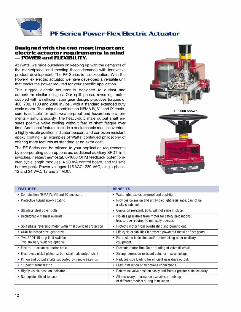
Designed with the two most importantelectric actuator requirements in mind— POWER and FLEXIBILITY.
At Watts, we pride ourselves on keeping up with the demands ofthe marketplace, and meeting those demands with innovativeproduct development. The PF Series is no exception. With thePower-Flex electric actuator, we have developed a versatile unitthat packs the power required for your specific application.
This rugged electric actuator is designed to outlast and outperform similar designs. Our split phase, reversing motor,coupled with an efficient spur gear design, produces torques of400, 700, 1100 and 2000 in./lbs., with a standard extended dutycycle motor. The unique combination NEMA IV, VII and IX enclo-sure is suitable for both weatherproof and hazardous environ-ments - simultaneously. The heavy-duty male output shaft en-sures positive valve cycling without fear of shaft fatigue overtime. Additional features include a declutchable manual override,a highly visible position indicator beacon, and corrosion resistantepoxy coating - all examples of Watts’ continued philosophy ofoffering more features as standard at no extra cost.
The PF Series can be tailored to your application requirementsby incorporating such options as: additional auxiliary SPDT limitswitches, heater/thermostat, 0-1000 OHM feedback potentiom-eter, cycle length modules, 4-20 mA control board, and fail safebattery pack. Power voltages 115 VAC, 230 VAC, single phase,12 and 24 VAC, 12 and 24 VDC.
PF Series Power-Flex Electric Actuator
FEATURES BENEFITS
• Combination NEMA IV, VII and IX enclosure • Watertight, explosion-proof and dust-tight.
• Protective hybrid epoxy coating • Provides corrosion and ultraviolet light resistance; cannot beeasily scratched.
• Stainless steel cover bolts • Corrosion resistant; bolts will not seize in place.
• Declutchable manual override • Isolates gear drive from motor for safety precautions; less torque required to manually operate.
• Split phase reversing motor w/thermal overload protection • Protects motor from overheating and burning out.
• 4140 hardened steel gear drive • Life cycle capabilities far exceed powdered metal or fiber gears.
• Two SPDT 15 amp limit switches, • For position indication and/or interlocking other auxiliaryTwo auxiliary switches optional equipment.
• Electro - mechanical motor brake • Prevents motor Run-On or hunting of valve disc/ball.
• Electroless nickel plated carbon steel male output shaft • Strong, corrosion resistant actuator - valve linkage.
• Pinion and output shafts supported by needle bearings • Reduces side loading for efficient gear drive output.
• 16 point terminal strip • Easy installation of all options connections.
• Highly visible position indicator • Determine valve position easily and from a greater distance away.
• Nameplate affixed to base • All necessary information available; no mix upof different models during installation.
PF2000 shown
13
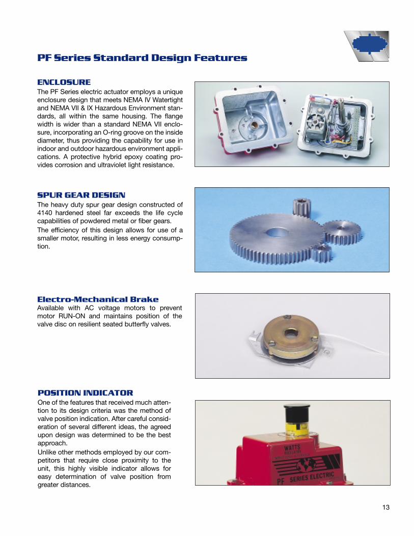
SPUR GEAR DESIGNThe heavy duty spur gear design constructed of4140 hardened steel far exceeds the life cyclecapabilities of powdered metal or fiber gears.The efficiency of this design allows for use of asmaller motor, resulting in less energy consump-tion.
Electro-Mechanical BrakeAvailable with AC voltage motors to preventmotor RUN-ON and maintains position of thevalve disc on resilient seated butterfly valves.
POSITION INDICATOROne of the features that received much atten-tion to its design criteria was the method ofvalve position indication. After careful consid-eration of several different ideas, the agreedupon design was determined to be the bestapproach.Unlike other methods employed by our com-petitors that require close proximity to theunit, this highly visible indicator allows foreasy determination of valve position fromgreater distances.
ENCLOSUREThe PF Series electric actuator employs a uniqueenclosure design that meets NEMA IV Watertightand NEMA VII & IX Hazardous Environment stan-dards, all within the same housing. The flangewidth is wider than a standard NEMA VII enclo-sure, incorporating an O-ring groove on the insidediameter, thus providing the capability for use inindoor and outdoor hazardous environment appli-cations. A protective hybrid epoxy coating pro-vides corrosion and ultraviolet light resistance.
PF Series Standard Design Features

14
Additional Limit SwitchesFor position indication and/or interlocking otherauxiliary equipment.
Cycle Length Control ModuleCan be factory installed for applications where fastopening or closing are not warranted. Cycle time canbe field adjustable up to 10 minutes.
0-1000 OHM PotentiometerProvides a resistance feedback proportional to theactuators position.
Heater and ThermostatMaintains a constant 70°F temperature in cold climatesand eliminates condensation in high humidity areas.
4-20 mAControl BoardWatts 4-20 mA controlboards are factoryinstalled and availablewith the 115 VACmotor only. The 4-20mA input providesmodulating control forvalves, dampers andother devices requiringaccurate positioningcontrol. In response toinput command signal, the control board supplies elec-trical power to the motor driving the actuator in the direc-tion necessary to bring the system into balance. Zero,Range and Anti-Hunt adjustments are easily accessiblefor field adjustment. Direct acting or reverse actingmodes, as well as, split range signals are optional.
FailsafeElectricActuatorsWatts PF Series fail-safe electric actuatorsfeature rechargeablebattery packs builtinto the actuator en-closure. Torque out-puts of 400-2000in./lbs. are available.All optional voltagesare available. A built-intrickle charger (automatic battery recharge) maintainsbattery life. The actuator is capable of 25 continuouscycles under full load without recharging batteries. Theoutside of the housing has a low battery charge indica-tor light. A remote local switch inside the housing facili-tates start up an/or maintenance.
PF Series Options and Controls

15
PF Series Specifications
MOTOR BRAKEElectro-mechanical motor brake to prevent motorRun-On
MANUAL OVERRIDEDeclutchable, wrench operated PF400, PF700 andPF1100. Declutchable handwheel operated PF2000.
CONDUIT CONNECTION1⁄2" NPT; optional 2nd connection available
AVAILABLE OPTIONS• Auxiliary SPDT 15 amp limit switches (2)
• Heater/thermostat
• Extended duty cycle motors
• 4-20 mA positioner board
• 4-20 mA control board with 4-20 mA Feedback
• 0-1000 OHM feedback potentiometer
• Cycle length control module
• Multi-turn operation
• Power Voltages:
230 VAC, single phase12 & 24 VDC, 12 & 24 VAC
• Fail safe battery pack
• CSA-Nema IV; PF700 and 1100
TORQUE400, 700, 1100 and 2000 in./lbs.
ENCLOSURECombination NEMA IV Watertight andNEMA VII and IX Hazardous Environment:
Class I, groups C and D,
Class II, group E, F and G.
ENCLOSURE FINISHHybrid epoxy coating with ultraviolet light inhibitor
MOTORCapacitor start/run split phase reversing withthermal overload protection (AC models only)Voltages available in 115 VAC (Standard), 230 VAC,12 & 24 VAC, and 12 & 24 VDC.
TEMPERATURE LIMITS-40°F (with heater & thermostat) to maximum 150°F
OUTPUT CONNECTIONMale output shaft
GEARINGHardened 4140 steel spur gear design; permanentlylubricated
LIMIT SWITCHESTwo SPDT 15 amp standard; cam operated andadjustable to 300°
ENGINEERING DATA
Note: Amp rating is considered locked rotor.Duty cycle @ ambient temperature.
115VAC 230VAC 12VDC 24VDC 12VAC 24 VAC CycleTorque Amp Duty Amp Duty Amp Duty Amp Duty Amp Duty Amp Duty Time/90° Weight
Model in./lbs. Draw Cycle Draw Cycle Draw Cycle Draw Cycle Draw Cycle Draw Cycle (Sec.) (Lbs.)PF400 400 .05 100% .8 75% 2.0 75% 4.0 75% 2.0 75% 3.0 75% 10 10PF700 700 .75 75% .8 50% 2.0 75% 4.0 75% 2.0 75% 3.0 75% 10 10PF1100 1100 .05 100% .8 75% 2.0 75% 4.0 75% 2.0 75% 3.0 75% 25 11PF2000 2000 1.00 65% .8 50% 2.0 75% 4.0 75% 2.0 75% 3.0 75% 25 15

16
PF Materials of Construction
ITEM QTY. DESCRIPTION MATERIAL
1 1 Base Aluminum, Hybrid Epoxy Coated3 1 Base Plate Aluminum4 1 Cover Aluminum, Hybrid Epoxy Coated5 1 Shaft Main Carbon Steel,
Electroless Nickel Plated7 2 Pin Carbon Steel8 1 Shaft Stub Carbon Steel9 1 Spur Gear Carbon Steel10 1 Spur Gear Carbon Steel11 1 Gear Pinion Carbon Steel12 2 Pinion Bearing Bronze13 1 Spur Gear Bearing Bronze14 1 Gear Main Carbon Steel15 1 Shaft Inner Carbon Steel, Zinc Plated16 1 Shaft Retainer Carbon Steel,
Electroless Nickel Plated17 1 Position Indicator Polycarbonate18 1 Override Knob Aluminum, Hybrid Epoxy Coated19 1 Collar Polycarbonate20 1 Cover Bearing Bronze21 1 Base Plate Bearing Bronze22 1 Base Bearing Bronze23 2 Cam Aluminum24 1 Terminal Block25 2 Switch26 1 O-Ring Base/Cover Buna-N27 1 Capacitor28 1 Capacitor29 1 Clamp, Capacitor30 1 Motor31 1 Shell Aluminum32 1 Spring33 2 Screw Round Hd. 4-40 x 1.00 Lg.34 1 Washer, Flat #10 .45 Dia. x .06 Thk.35 3 Screw, Flat Hd. 8-32 x .25 Lg. Stainless Steel36 8 Screw, Hex Hd. 5/16-18 x 1.00 Lg. Stainless Steel37 1 Screw, Self Tapping
Slot/Hex (Green) #10 x .5 Lg.38 1 Key, Woodruff 3/3239 1 Screw, Slot Set 8-32 x .5 Lg. Stainless Steel40 4 Screw, Set 8-32 x .12 Lg.41 4 Screw, Self Tapping #4 x .5 Lg.42 5 Screw, Self Tapping Slot/Hex #10 x .5 Lg.43 4 Screw, Slot/Hex 10-32 x 1.62 Lg.44 1 Seal, Base Buna-N45 1 Seal, Cover Buna-N46 1 O-Ring, Shaft Buna-N
Note: Items 8, 9,10,13 and 27 are for 1100 and 2000 in./lb. units only.Item 18 is a 10" diameter handwheel on PF-2000.
Series PF 400, 700 and 1100 shown.
39
35
18
17
19
45
36
4
2043
29
2827
23
40
41
1646
3432
31
24
37
153
2111
9
10
12
38
13
14
22
28
441
7
5
8
38
33
25
42
30

17
PF Dimensions
1⁄2" NPTconduit connection
9.25
PF400, PF700, PF1100
MOUNTING DIMENSIONS
1.06 dia.
8.221.62 SQ.
.81
5⁄16-24 UNF (4) places
.371 +.005-.000
2.25 dia.
9.38
.75
10.00 dia.
11.60
WARNING:Always disconnectpower before re-moving cover.Keep coversecurely fastenedwhen in service.TO OVERRIDE:Pull up indicator,apply 5/8” wrenchto exposed flats,turn within arrows.TO REMOVECOVER: Loosenoverride knobscrew, remove 8cover bolts and liftoff cover.
4-20mA positioneroption has
additional 1⁄2" NPTconduit connection
PF2000
18
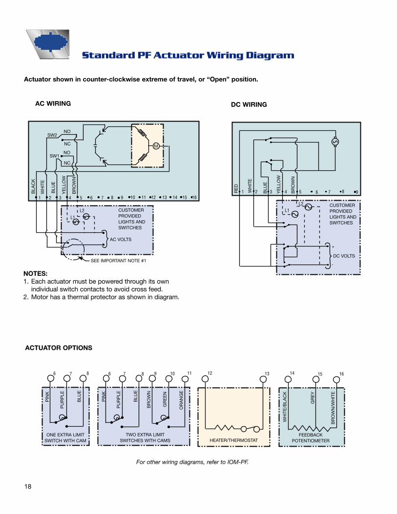
NOTES:1. Each actuator must be powered through its own
individual switch contacts to avoid cross feed.2. Motor has a thermal protector as shown in diagram.
Actuator shown in counter-clockwise extreme of travel, or “Open” position.
Standard PF Actuator Wiring Diagram
AC WIRING DC WIRING
ACTUATOR OPTIONS
For other wiring diagrams, refer to IOM-PF.
SW2
BLA
CK
PIN
K
PU
RP
LE
BLU
E
PIN
K
PU
RP
LE
BLU
E
BR
OW
N
GR
EE
N
OR
AN
GE
WH
ITE
/BLA
CK
GR
EY
BR
OW
N/W
HIT
E
WH
ITE
BLU
E
YE
LLO
W
BR
OW
N
NO
NC
NO
NC
CUSTOMERPROVIDEDLIGHTS ANDSWITCHES
CUSTOMERPROVIDEDLIGHTS ANDSWITCHES
M
SW1
1 2
6 7 8 6 7 8 9 10 11 12 13 14 15 16
3 4 5 6
L2L1
L2L1
7 8 9
RE
D
WH
ITE
BLU
E
YE
LLO
W
BR
OW
N
1 2 3 4 5 6 7 8 9
+
-
10 11 12 13 14 15 16
AC VOLTS
ONE EXTRA LIMITSWITCH WITH CAM
TWO EXTRA LIMITSWITCHES WITH CAMS HEATER/THERMOSTAT
FEEDBACKPOTENTIOMETER
DC VOLTSSEE IMPORTANT NOTE #1
19
LVW Series Electric Actuators
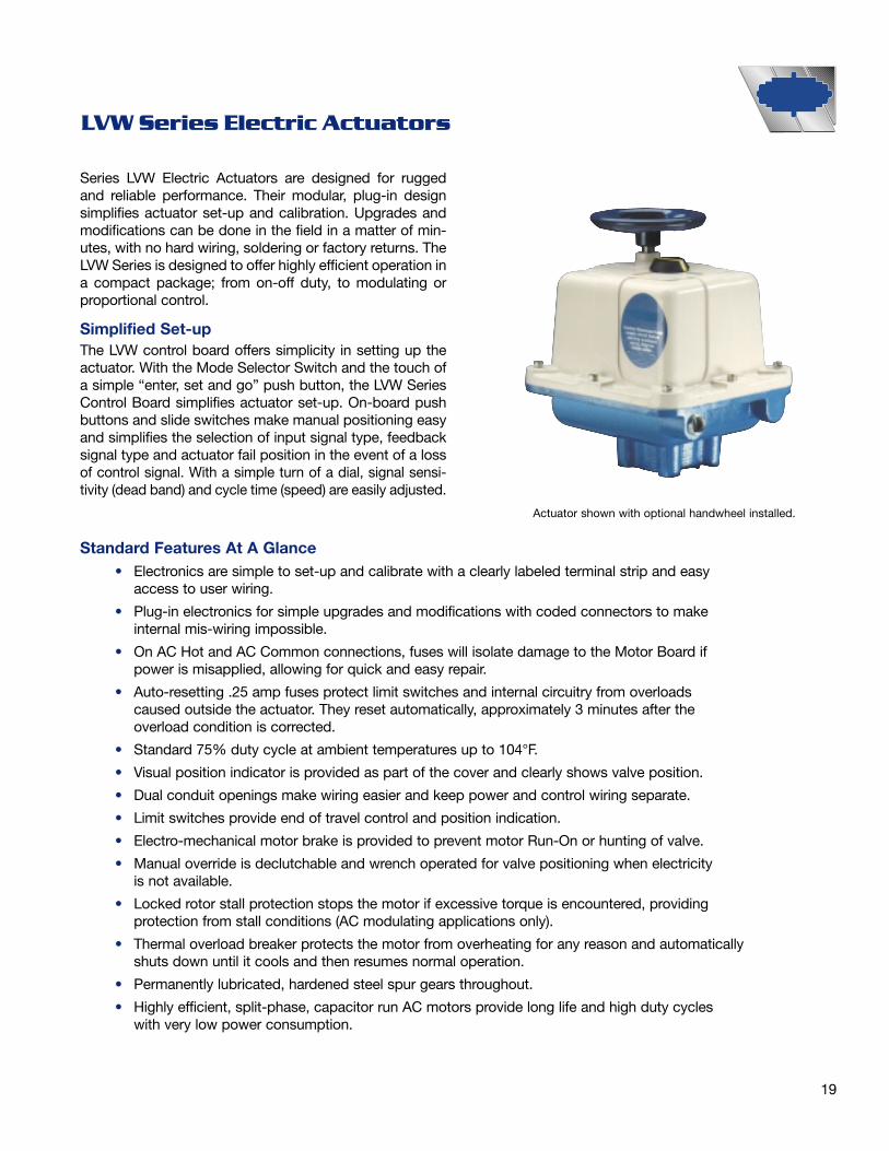
Series LVW Electric Actuators are designed for ruggedand reliable performance. Their modular, plug-in designsimplifies actuator set-up and calibration. Upgrades andmodifications can be done in the field in a matter of min-utes, with no hard wiring, soldering or factory returns. TheLVW Series is designed to offer highly efficient operation ina compact package; from on-off duty, to modulating orproportional control.
Simplified Set-upThe LVW control board offers simplicity in setting up theactuator. With the Mode Selector Switch and the touch ofa simple “enter, set and go” push button, the LVW SeriesControl Board simplifies actuator set-up. On-board pushbuttons and slide switches make manual positioning easyand simplifies the selection of input signal type, feedbacksignal type and actuator fail position in the event of a lossof control signal. With a simple turn of a dial, signal sensi-tivity (dead band) and cycle time (speed) are easily adjusted.
Standard Features At A Glance• Electronics are simple to set-up and calibrate with a clearly labeled terminal strip and easy
access to user wiring.
• Plug-in electronics for simple upgrades and modifications with coded connectors to makeinternal mis-wiring impossible.
• On AC Hot and AC Common connections, fuses will isolate damage to the Motor Board ifpower is misapplied, allowing for quick and easy repair.
• Auto-resetting .25 amp fuses protect limit switches and internal circuitry from overloadscaused outside the actuator. They reset automatically, approximately 3 minutes after theoverload condition is corrected.
• Standard 75% duty cycle at ambient temperatures up to 104°F.
• Visual position indicator is provided as part of the cover and clearly shows valve position.
• Dual conduit openings make wiring easier and keep power and control wiring separate.
• Limit switches provide end of travel control and position indication.
• Electro-mechanical motor brake is provided to prevent motor Run-On or hunting of valve.
• Manual override is declutchable and wrench operated for valve positioning when electricityis not available.
• Locked rotor stall protection stops the motor if excessive torque is encountered, providingprotection from stall conditions (AC modulating applications only).
• Thermal overload breaker protects the motor from overheating for any reason and automaticallyshuts down until it cools and then resumes normal operation.
• Permanently lubricated, hardened steel spur gears throughout.
• Highly efficient, split-phase, capacitor run AC motors provide long life and high duty cycleswith very low power consumption.
Actuator shown with optional handwheel installed.

20
LVW Series Specifications
LVW Series Control Board Specifications115VAC and 230VAC Modulating Applications
Temperature Range 32°F to 150°F (without heater and thermostat), -40°F to 150°F (with heater and thermostat)
Conduit Connections (2) 3⁄4" NPT
Mounting ISO 5211 F07 and F10 bolt circles with 1" female square
Torque Output Upon power up, the actuator supplies the rated torque when it is needed to break the valve away from its seat
Duty Cycle AC applications: The actuator may run continuously at ambient temperatures at or below 104°F for up to 15 minutes. After running for 15 minutes, actuators may operate up to 75% duty cycle (that is, between each 90 degree rotation, the actuator must rest for 1⁄3 of the 90° cycle time)
Note: AC Applications: At 50Hz, the duty cycle is 60% @ 104°F. DC Applications: Continuous
Voltage 115VAC (50 or 60 Hz), 230 VAC (50 or 60 Hz), 12 VDC, 24 VDC
Limit Switches (2) Single pole, double throw switches rated for 1⁄3 hp, 10 amps @ 115/230VAC, CSA certified, fuse protected. The two standard switches are used for end of travel control, and may also be used for pilot or position indication in on/off or jogging applications.
Motor AC Applications: Split phase, capacitor driven motor with Class B or better insulation; sub-fractional horsepower.
DC Applications: Brushed, DC, sub-fractional horsepower.
Lubrication Permanently lubricated gear train and bearings
Gear Train Hardened steel spur gears
Approximate Weight 31 lbs. for NEMA 4/4X/7/9 (21 lbs. in NEMA 4/4x applications)
Enclosure Base: die cast aluminumCover: NEMA 4/4x - PVC w/UV inhibitorsCover: NEMA 4/4x/7/9 - Cast aluminum
Input Impedence Voltage Input 35k ohms; Current Input 200 ohms
Control Signal May be either 4-20mA or 0-10VDC (selectable via on-board slide switch). Fully compatible with ISA-S50.1 as a type 4, class L, power isolated device. Input minus and transmit minus are tied together and isolated from power and earth ground.
Position Either 4-20mA or 0-10VDC (jumper Readback selectable) Minimum resistive load for volt-Signal age input 1k ohm. Maximum resistive load
for current input: 500k ohmLocked Rotor If actuator cannot achieve position Protection commanded by control signal after
2 seconds, it will stall motor. Actuator will remain stalled until the control signal commands it to drive in the opposite direction.
Control Fail In event of loss of control signal Position (with power still supplied), user can
choose between Zero and Last via slide switch.
Note: If the minimum control signal = ø, fail position must be last.
Cycle Rate User can choose 90° rotation times of :(Speed) Control normal, 2x normal, 3x normal,
5x normal, and 10x normal.
Dead Band The amount of change in control signal that the actuator will ignore before the output shaft begins to move. Adjustable from 1% to 3%.
Accuracy 1% (dead band settings)
Repeatability For any given control signal value, the ability of the actuator to drive to same physical position (i.e., a 12mA signal should result in a 45° actuator output position). ± 1%
Resolution The smallest amount of actuator response that can be obtained by changing the input signal. 1%
Split Range Actuator may accept split range (i.e., 4-12mA or 12-20mA) control signal with no wiring changes.
Reverse Acting With no wiring changes required, the actuator may be calibrated to drive clock-wise upon increasing control signal, and counter-clockwise upon decreasing control signal.
On-Board Push buttons override the analog control Supervisory signal, allowing the user to manually Control position the valve.
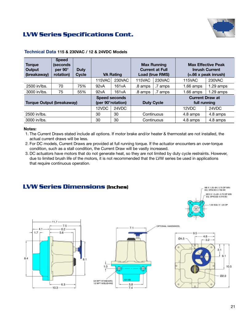
Technical Data 115 & 230VAC / 12 & 24VDC Models
SpeedTorque (seconds Max Running Max Effective PeakOutput per 90° Duty Current at Full Inrush Current(breakaway) rotation) Cycle VA Rating Load (true RMS) (=.66 x peak inrush)
115VAC 230VAC 115VAC 230VAC 115VAC 230VAC2500 in/lbs. 70 75% 92vA 161vA .8 amps .7 amps 1.66 amps 1.29 amps3000 in/lbs. 75 55% 92vA 161vA .8 amps .7 amps 1.66 amps 1.29 amps
Speed seconds Current Draw at Torque Output (breakaway) (per 90°rotation) Duty Cycle full running
12VDC 24VDC 12VDC 24VDC2500 in/lbs. 30 30 Continuous 4.8 amps 4.8 amps3000 in/lbs. 30 30 Continuous 4.8 amps 4.8 amps
Notes:1. The Current Draws stated include all options. If motor brake and/or heater & thermostat are not installed, the
actual current draws will be less.2. For DC models, Current Draws are provided at full running torque. If the actuator encounters an over-torque
condition, such as a stall condition, the Current Draw will be vastly increased.3. DC actuators have motors that do not generate heat, so they are not limited by duty cycle restraints. However,
due to limited brush life of the motors, it is not recommended that the LVW series be used in applications that require continuous operation.
21
LVW Series Specifications Cont.
LVW Series Dimensions (Inches)
11.7

2
1
1812
17
10
3
87
9
13
411
14
5
6
16
15
22
Series LVW Spare Parts and Option Kits
Spare PartsItem Description Part #
1 Cover with Position IndicatorCast Aluminum 9301PVC 97145
2 Position Indication Knob* 913923 Cover Screw 915644 Pot/Cam Shaft Gears
90° Operation 99090180° Operation 99180270° Operation 99270
5 Override Shaft* 930236 Motor Gearbox
115VAC 90201230VAC 90202
7 Limit Switch 10208 2 Cams with Set Screw 913529 Capacitor with Wires
115VAC 93061230VAC 93071
10 Mounting Bracket, Motor Board, Lwr. 9169811 Mounting Bracket, Motor Board, Upr. 9168812 Motor Board with Screws
115VAC 92015230VAC 92030
13 Brake 99715
Option Kits14 Feedback Potentiameter 9920015 2 Extra SPDT Limit Switches 9900016 Terminal Block
1-6 Connections 914201-12 Connections 91430
17 Heater Thermostat115VAC 99515230VAC 99523
18 Control Board 99642Declutchable Hand Wheel (not shown) 9098* Indicates items sold as replacement parts only. Consult Watts forreplacement parts ordering codes.

23
LVW Series Wiring Diagrams
Motor Board WiringTerminal 6 CW Limit (Line Voltage Out)Terminal 5 CCW Limit (Line Voltage Out)Terminal 4 CW AC Hot (Must Connect)Terminal 3 CCW AC Hot (Must Connect)Terminal 2 AC Common (Must Connect)Terminal 1 AC Hot (For Heater Option)
Caution: AC voltage actuators use reversing induction motors which cause high voltages. Devices connected toterminal 3 and terminal 4 must be rated for a minimum 250VAC (550VAC for 230VAC applications). Due to theinduced feedback voltage, multiple actuators can not be wire in parallel. Separate isolated contacts must be providedfor each actuator.
115VAC and 230VAC with Modulating Control
Motor Board Wiring, Control Board InstalledTerminal 2 AC Common (Must Connect)Terminal 1 AC Hot
Caution: When control board is installed, power to terminal 3 or terminal 4 will damage electronic circuit boards. Use“CW” Clockwise and “CCW” Counter Clockwise buttons to drive actuator.
115VAC and 230VAC On/Off Applications

24
LVW Series Suggested Actuator Specification115VAC and 230VAC Standard Electric Actuator
GeneralThe quarter-turn electric actuator will comply with Part 15,Class A of the FCC regulations for emissions and con-ducted radiation. It will also be certified by the CanadianStandard Association (CSA) for weathertight or weather-tight and hazardous locations. It will be composed of acompact cast aluminum housing, motor, gearing, limitswitches controlled by metal cams for end of travel con-trol, electro-mechanical motor brake, mechanical positionindicator, and declutchable override as one complete unit.Composite (non-metallic) housing covers are permittedfor non-hazardous locations. All internal connections(motor leads, limit switch leads, option connectors, etc.)will be coded, using different style connectors for eachfunction to prevent mis-wiring. All connections will plug-into simplify field repairs and upgrades. No preventive orperiodic maintenance of any type will be required.MotorThe motor will be capable of running continuously at fulltorque for up to 15 minutes at ambient temperatures at orbelow 104°F. Subsequently, the motor must be capable of75% duty cycle. Motors will be split phase, capacitor driv-en with an auto reset thermal sensor and will provide highstarting torque and be totally enclosed within the actuatorhousing cover.LubricationAll rotating power train components will be coated with amulti-purpose grease. Lubricants will be suitable forambient conditions of -40°F to 150°F. For temperaturesbetween 32°F and -40°F a heater and thermostat assemblyshould be provided.GearingThe powertrain will be comprised of hardened steel,machine cut spur gears. Stamped or cast gearing will notbe allowed.Manual OperationA wrench-operated override shaft will be provided formanual operation. As an option, a metallic hand wheelmay also be provided. The override device will beengaged through a declutching mechanism that sepa-rates the final output drive from the motor output.Limit SwitchesActuators will have two standard end of travel switches,single pole double throw, rated at 10 amps at 115/230VAC. The limit switches will be activated by metal camsmounted on the actuator drive shaft. At the end of travel,the power will be routed through the limit switches to aterminal strip location for pilot or position indication appli-cations. The limit indicator outputs will be fuse protectedwith auto-resetting polyfuses with a working limit of 0.25
amps to protect the limit switches and internal circuitryfrom possible overloads originating outside the actuator.To simply maintenance, these polyfuses will be perma-nent and do not need to be replaced. They reset auto-matically after the overload condition is corrected - inapproximately 3 minutes. Two additional limit switchesmay be added to the actuator, adjustable to operate atany position, as required by the process application.Open/Close OperationOpen/Close actuators will be controlled via two, pow-ered, maintained contacts, one for driving in the clock-wise direction and one for driving in the counter-clock-wise direction. Power may be removed mid-stroke toposition the valve. The AC input power will be fuse pro-tected on both AC Hot and AC Common. The fuses willnever blow in normal operation and will be conservativelyrated and soldered in place for high reliability.Proportional Control (Modulating Operation)Modulating control actuators will accept a variable, pro-portional 4-20 mA or 0-10VDC valve position signal andrespond by positioning the valve linearly with an accura-cy of 1%. Normally, the actuator will drive clockwise inresponse to a decreasing control signal; however, theactuator will be capable of “reverse acting” operation(driving counter-clockwise in response to a decreasingcontrol signal) with no necessitated internal wiringchanges. The actuator will also supply a 4-20 mA or 0-10VDC position re-transmit signal, and provide the abilityto adjust the cycle time of the actuator via motor pulsing.A slide switch will enable the user to set the actuatorresponse to a loss of control signal. Locked rotor protec-tion will detect whenever the actuator is unable toachieve the position commanded by the control signaland will terminate power to the motor in order to preventdamage due to repeated stall conditions.

25
EA350 Series Unidirectional Electric ActuatorFor Quarter-Turn Applications
Series EA350 Unidirectional Electric Actuators are specificallydesigned for use with ball valves and other applicationsrequiring a compact, high efficiency actuator. The EA350Series is offered in 115VAC and 24VAC models with standard8 and 35 second cycle times for 90° rotation; 24VAC cycletime is 18 and 40 seconds (25 seconds for 21⁄2" - 3").The EA350 is ideal for use with Watts 1⁄4" - 3" B-6400 seriesstandard port ball valves.
Features• High efficiency, extremely compact size
• Standard 100% duty cycle*
• Hardened precision gear train
• Permanently lubricated
• Unique visual indicator on side of actuator housing, in addition to standard visual indicator
• Standard terminal strip connections
• Standard manual override
• Mounting pattern identical to Watts PneumaticActuators
• Heavy duty shaded pole motor
• Adjustable start/stop positions
• UL listed components
• Standard auxiliary SPDT switch
• Standard NEMA-4 construction*EA350 units will deliver max. rated torque for 1 hr. continuous.
Terminal FunctionsTerminal # Function Output Shaft Positions
1 Makes when output shaft flatsare perpendicular to housing
2 Auxiliary Common Terminal
3 Makes when output shaft flatsare parallel to housing
4 When powered, output shaft rotates untilflats are perpendicular to housing length
5 Operating Common
6 When powered, output shaft rotates untilflats are parallel to housing length
All illustrationsare shown
viewed frombottom (outputshaft side) of
actuator
2626
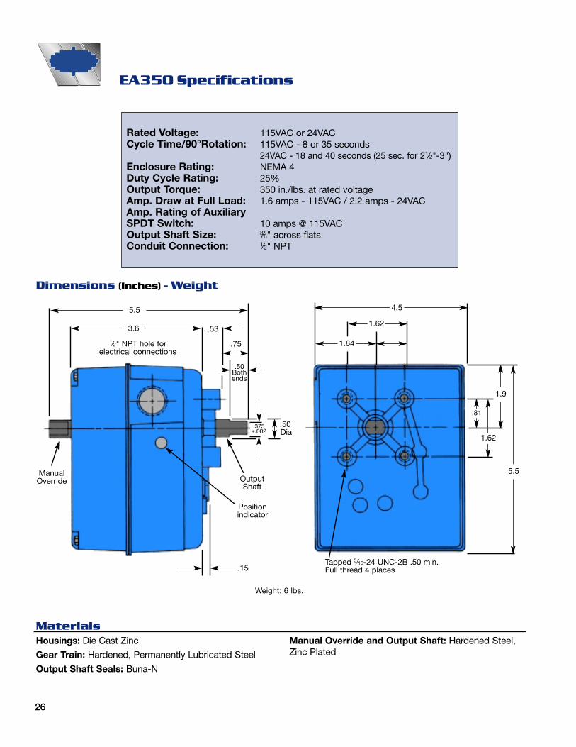
EA350 Specifications
Rated Voltage: 115VAC or 24VACCycle Time/90°Rotation: 115VAC - 8 or 35 seconds
24VAC - 18 and 40 seconds (25 sec. for 21⁄2"-3")Enclosure Rating: NEMA 4Duty Cycle Rating: 25%Output Torque: 350 in./lbs. at rated voltageAmp. Draw at Full Load: 1.6 amps - 115VAC / 2.2 amps - 24VACAmp. Rating of AuxiliarySPDT Switch: 10 amps @ 115VACOutput Shaft Size: 3⁄8" across flatsConduit Connection: 1⁄2" NPT
Dimensions (Inches) - Weight
MaterialsHousings: Die Cast Zinc
Gear Train: Hardened, Permanently Lubricated Steel
Output Shaft Seals: Buna-N
1⁄2" NPT hole for electrical connections
5.5
3.6 .53
.75
.50Bothends
.50Dia
OutputShaft
Positionindicator
.15Tapped 5⁄16-24 UNC-2B .50 min.Full thread 4 places
4.5
1.62
1.84
1.9
5.5
1.62
.81
ManualOverride
.375±.002
Weight: 6 lbs.
Manual Override and Output Shaft: Hardened Steel,Zinc Plated

2727
In order to provide properly sized butterfly valve and actuator units to meet specific applications, it is
important that Watts be provided as much of the following data as possible. Please note that Watts
provides the following standard features with its actuators.
1. A motor brake is standard with electric actuators to prevent motor Run-On or hunting of valve position.
2. Pneumatic actuators standardly sized at 80 psi air supply pressure. Consult Watts when using an air
supply of less than 80 psi.
3. Solenoid valves mounted directly to the pneumatic actuator housing when ordered with Watts
pneumatic actuators.
1. Valve information:A. Model No. ––––––––––––––––––––––––––––– Size –––––––––––––––––––– Quantity –––––––––––––––––––B. Media –––––––––––––––––––––––––––––––– Inlet Pressure ––––––––––––––
Differential Pressure –––––––––––––––––––– System Velocity ––––––––––––System GPM –––––––––––––––––––––––––– Temperature –––––––––––––––
2. Actuator information:A. Electric
Voltage: 115 VAC ❏ 230 VAC ❏
Time for 90° Rotation: Standard ❏ Required ––––––––––––– (Sec.) ❏
Type Enclosure: NEMA 4 (Weather proof) ❏ NEMA 7 (Explosion proof) ❏
Special Requirements: Modulating Control ❏ Heater & Thermostat ❏
Extra SPDT Switches ❏ Position Transmitter ❏
Potentiometer ❏
B. Pneumatic
Actuator air supply: 80 psi ❏ Other ––––––––––––––––– (psi) ❏
Actuator Type: Air to Air ❏ Pneumatic Speed Control ❏
Air to Spring ❏ Failsafe: Open ❏ Closed ❏
Solenoid Valve: NEMA 4 (Weather proof) ❏ NEMA 7 (Explosion proof) ❏
Switch Box: NEMA 4 (Weather proof) ❏ NEMA 7 (Explosion proof) ❏
Extra SPDT, Qty ––––––––––– ❏
Positioner: 3-15 psi ❏ 4-20mA –––––––––––––––––––– ❏
3. Special Notes:
Valve Actuation Data Sheet

HEADQUARTERS: Watts Regulator Company 815 Chestnut St., North Andover, MA 01845-6098 U.S.A. 978 688-1811 978 794-1848
Edwards, Platt & Deely, Inc. 271 Royal Ave., Hawthorne, NJ 07506 973 427-2898 973 427-4246Edwards, Platt & Deely, Inc. 368 Wyandanch Ave., North Babylon, NY 11703 631 253-0600 631 253-0303W. P. Haney Co., Inc. 51 Norfolk Ave., South Easton, MA 02375 508 238-2030 508 238-8353
J. B. O’Connor Company, Inc. P.O. Box 12927, Pittsburgh, PA 15241 724 745-5300 724 745-7420RMI Glenfield Bus. Ctr., 2535 Mechanicsville Tpk., Richmond, VA 23223 804 643-7355 804 643-7380The Joyce Agency, Inc. 8442 Alban Rd., Springfield, VA 22150 703 866-3111 703 866-2332Vernon Bitzer Associates, Inc. 980 Thomas Drive, Warminster, PA 18974 215 443-7500 215 443-7573WMS Sales, Inc. (Main office) 9580 County Rd., Clarence Center, NY 14032 716 741-9575 716 741-4810
Billingsley & Associates, Inc. 2728 Crestview Ave., Kenner, LA 70062-4829 504 602-8100 504 602-8106Billingsley & Associates, Inc. 478 Cheyenne Lane, Madison, MS 39110 601 856-7565 601 856-8390Francisco J. Ortiz & Co., Inc. Charlyn Industrial Pk., Road 190 KM1.9 - Lot #8, Carolina, Puerto Rico 00983 787 769-0085 787 750-5120Mid-America Marketing, Inc. 203 Industrial Drive, Birmingham, AL 35211 205 879-3469 205 870-5027Mid-America Marketing, Inc. 1364 Foster Avenue, Nashville, TN 37210 615 259-9944 615 259-5111Mid-America Marketing, Inc. 5466 Old Hwy. 78, Memphis, TN 38118 901 795-0045 901 795-0394Smith & Stevenson Co., Inc. 4935 Chastain Ave., Charlotte, NC 28217 704 525-3388 704 525-6749Spotswood Associates, Inc. 6235 Atlantic Blvd., Norcross, GA 30071 770 447-1227 770 263-6899Target Marketing Enterprises, Inc. 118 West Grant St., Building M, Orlando, FL 32806 407 245-7838 407 245-7833
Aspinall Associates, Inc. 6840 Hillsdale Court, Indianapolis, IN 46250 317 849-5757 317 845-7967Dave Watson Associates 1325 West Beecher, Adrian, MI 49221 517 263-8988 517 263-2328Disney McLane & Associates 428 McGregor Ave., Cincinnati, OH 45206 800 542-1682 877 476-1682BWA Company 17610 S. Waterloo Rd., Cleveland, OH 44119 216 486-1010 216 486-2860Mid-Continent Marketing Services Ltd. 1724 Armitage Ct., Addison, IL 60101 630 953-1211 630 953-1067Soderholm & Associates, Inc. 7150 143rd Ave. N.W., Anoka, MN 55303 763 427-9635 763 427-5665Stickler & Associates 333 North 121 St., Milwaukee, WI 53226 414 771-0400 414 771-3607
Hugh M. Cunningham, Inc. 13755 Benchmark, Dallas, TX 75234 972 888-3808 972 888-3838Mack McClain & Associates 11132 South Towne Square, Suite 202, St. Louis, MO 63123 314 894-8188 314 894-8388Mack McClain & Associates, Inc. 1450 NE 69th Place, Ste. 56 Ankeny, IA 50021 515 288-0184 515 288-5049Mack McClain & Associates, Inc. 15090 West 116th St., Olathe, KS 66062 913 339-6677 913 339-9518OK! Sales, Inc. 2200 Blue Creek Dr., Norman, OK 73026 405 360-6161 405 360-0092Phoenix Marketing, Ltd. 2416 Candelaria N.E., Albuquerque, NM 87107 505 883-7100 505 883-7101
Delco Sales, Inc. 1930 Raymer Ave., Fullerton, CA 92833 714 888-2444 714 888-2448Delco Sales, Inc. 111 Sand Island Access Rd., Unit I-10, Honolulu, HI 96819 808 842-7900 808 842-9625Fanning & Associates, Inc. 6765 Franklin St., Denver, CO 80229-7111 303 289-4191 303 286-9069Hollabaugh Brothers & Associates 6915 South 194th St., Kent, WA 98032 253 867-5040 253 867-5055Hollabaugh Brothers & Associates 3028 S.E. 17th Ave., Portland, OR 97202 503 238-0313 503 235-2824P I R Sales, Inc. 3050 North San Marcos Place, Chandler, AZ 85225 480 892-6000 480 892-6096Preferred Sales 31177 Wiegman Road, Hayward, CA 94544 510 487-9755 510 476-1595R. E. Fitzpatrick Sales, Inc. 4109 West Nike Dr. (8250 South), West Jordan, UT 84088 801 282-0700 801 282-0600
Watts Industries (Canada) Inc.(Watts Regulator Co. Division) 5435 North Service Road, Burlington, Ontario L7L 5H7 905 332-4090 905 332-7068
Con-Cur West Marketing, Inc. #109-42 Fawcett Rd., Coquitlam, British Columbia V3K 6X9 604 540-5088 604 540-5084D.C. Sales, Ltd. 10-6130 4th St. S.E., Calgary, Alberta T2H 2A6 403 253-6808 403 259-8331D.C. Sales, Ltd. 11420 142 Street, Edmonton, Alberta T5M 1V1 780 496-9495 780 496-9621GTA Sales Team. Greater Toronto Area 888 208-8927 888 479-2887Hydro-Mechanical Sales, Ltd. 3700 Joseph Howe Dr., Ste. 1 Halifax, Nova Scotia B3L 4H7 902 443-2274 902 443-2275Hydro-Mechanical Sales, Ltd. 297 Collishaw St., Ste. 7 (shipping) Moncton, New Brunswick E1C 9R2 506 859-1107 506 859-2424Hydro-Mechanical Sales, Ltd. 85 Tolt Rd., St. Phillips, Newfoundland A1B 3M7 709 895-0090 709 895-0091Le Groupe B.G.T., Inc. 23 du Buisson, Pont Rouge, Quebec G3H 1X9 418 657-2800 418 657-2700Le Groupe B.G.T., Inc. 86 des Enterprises #208, Boisbriand, Quebec J7G 2T3 450 434-9010 450 434-9848Mar-Win Agencies, Ltd. 1123 Empress St., Winnipeg, Manitoba R3E 3H1 204 775-8194 204 786-8016Northern Mechanical Sales P.O. Box 280 (mailing) 163 Pine St. (shipping), Garson, Ontario P3L 1S6 705 693-2715 705 693-4394Palser Enterprises, Ltd. 1885 Blue Heron Dr., #4, London, Ontario N6H 5L9 519 471-9382 519 471-1049RAM Mechanical Marketing 1401 St. John St., Regina, Saskatchewan S4R 1S5 306 525-1986 306 525-0809RAM Mechanical Marketing 510 Ave M South, Saskatoon, Saskatchewan S7M 2K9 306 244-6622 306 244-0807Walmar Mechanical Sales 24 Gurdwara Rd., Nepean, Ontario K2E 8B5 613 225-9774 613 225-0673
EXPORT Hdqtrs.: Watts Regulator Co. 815 Chestnut St., North Andover, MA 01845-6098 U.S.A. 978 688-1811 978 794-1848
F-P/E-AC 9942 © Watts Regulator Co., 1998 Printed in U.S.A.
Fax #For Technical Assistance Call Your Authorized Watts Agent.
Can
ada
Telephone #S
out
hC
entr
al
0408
No
rth
Eas
tS
out
hE
ast
Watts USA website: www.wattsreg.comWatts Canada website: www.wattscanada.ca
Mid
Atla
ntic
No
rth
Cen
tral
Wes
tern