watermarking techniques for intellectual property ...€¦ · watermarking techniques for...
TRANSCRIPT

Watermarking Techniques for Intellectual
Property Protection in SOC Designs
Amr Talaat Abdel-Hamid
A Thesis
in
The Department
of
Electrical and Computer Engineering
Presented in Partial Fulfillment of the Requirements
for the Degree of Doctor of Philosophy at
Concordia University
Montreal, Quebec, Canada
September 2005
c© Amr Talaat Abdel-Hamid, 2005

CONCORDIA UNIVERSITY
Division of Graduate Studies
This is to certify that the thesis prepared
By: Amr Talaat Abdel-Hamid
Entitled: Watermarking Techniques for Intellectual Property Protec-
tion in SOC Designs
and submitted in partial fulfilment of the requirements for the degree of
Doctor of Philosophy
complies with the regulations of this University and meets the accepted standards
with respect to originality and quality.
Signed by the final examining committee:
Dr.
Dr. Claude Thibeault
Dr. Abdeslam En-Nouaary
Dr. Rachida Dssouli
Dr. Rajagopalan Jayakumar
Dr. Sofiene Tahar
Dr. El-Mostapha AboulHamid
Approved by
Chair of the ECE Department
2002
Dean of Engineering

iii
ABSTRACT
Watermarking Techniques for Intellectual Property
Protection in SOC Designs
Amr Talaat Abdel-Hamid, Ph. D.
Concordia University, 2005
Sharing Intellectual Property (IP) blocks in today’s competitive market poses
significant high security risks. Creators and owners of IP designs want assurances
that their content will not be illegally redistributed by consumers, and consumers
want assurances that the content they buy is legitimate. Recently, digital water-
marking emerged as a candidate solution for copyright protection of IP blocks.
In this thesis, we propose a new approach for watermarking IP designs based
on the embedding of the ownership proof as part of the IP design’s finite state ma-
chine (FSM). The approach utilizes coinciding as well as unused transitions in the
state transition graph of the design. Based on this approach, we have developed
a robust watermarking framework, used for copyright protection, as well as fragile
watermarking framework used for design authentication. For both frameworks, we
developed related algorithms for watermark insertion and extraction.
The developed techniques increase the robustness of the watermark and allow
a secure implementation, hence enabling the development of the first public-key IP
watermarking scheme at the FSM level. The algorithms have been implemented in
a prototype tool that accepts IPs in VHDL. We also define evaluation criteria for
IP watermarking, which we used for experimental measurements, and to compare
between different algorithms.

iv
In order to integrate these proposed algorithms in the design cycle of industrial
projects, we extend the above techniques to enable the watermarking of hierarchical
and concurrent designs. Finally, we introduce and describe the first algorithm for
watermarking hierarchical finite state machines (HFSMs).

v
To My Family:
My Dad, My Mom, and My only Sister

vi
ACKNOWLEDGEMENTS
I would like to express my gratitude to my supervisors, Dr. Sofiene Tahar,
and Dr. El-Mostapha AboulHamid, whose expertise, understanding, and patience,
added considerably to my graduate experience. I appreciate their vast knowledge
and skill in many areas. Dr. Tahar gave me the freedom to pursue this research,
even though it didn’t quite fit into the other projects in our research group. His
continuous support, and great effort was a corner stone in my research, and his great
personality have shaped my research career.
I would like to thank all members of my committee, Dr. Claude Thibeault
from Ecole de technologie superieure (ETS) for serving as my external examiner,
Dr. Rachida Dssouli, Dr. Rajagopalan Jayakumar, Dr. Abdeslam En-Nouaary, and
Dr. Ali Ghrayeb for the assistance they provided at all levels of the research project.
Finally, I would like to thank
Very special thanks go out to my colleagues in the Hardware Verification Group
(HVG), without their help, motivation and encouragement I would not have reached
this point in my research. I have spent six years in the HVG labs (between Masters
and PhD.) and will never forget the great moments, and achievements we had to-
gether during such golden years.
I would also like to thank my family for the support they provided me through
my entire life and in particular, I must acknowledge my dad whose research career
was always an inspiration, and his guidance is invaluable. I would love to express
my deep love and appreciation to my mother and sister, whom without their love,
encouragement and patience, I would have dropped my graduate studies long ago.
Also, a very special thanks goes to Mr. Magdy Hanna, my high school mathematics
teacher, his job affection and creative problem solving techniques have shaped my
life, and my career.
I would love to express my deep gratitude to many of the staff members at the

vii
Department of Electrical and Computer Engineering; they have always supported
and helped you to perform your job. Special thanks go to Tadeusz Obuchowicz, our
VLSI Specialist. I also would love to give my gratitude to Diane Moffat who was
always supportive and patient through out my whole graduate program.
In conclusion, I recognize that this research would not have been possible
without the financial assistance of the Microelectronics Strategic Alliance of Quebec
(RESMIQ) research fund, Concordia University School of Graduate Studies, Faculty
of Engineering and computer Science, and Department of Electrical and Computer
Engineering.

TABLE OF CONTENTS
LIST OF TABLES . . . . . . . . . . . . . . . . . . . . . . . . . . . . . . . . . xi
LIST OF FIGURES . . . . . . . . . . . . . . . . . . . . . . . . . . . . . . . . xii
LIST OF ACRONYMS . . . . . . . . . . . . . . . . . . . . . . . . . . . . . . xiii
1 Introduction and Motivation 1
1.1 System-on-a-Chip (SOC): Design Path and IP Blocks . . . . . . . . . 2
1.2 IP Protection . . . . . . . . . . . . . . . . . . . . . . . . . . . . . . . 5
1.3 Digital Watermarking . . . . . . . . . . . . . . . . . . . . . . . . . . . 7
1.3.1 Robust Watermarking . . . . . . . . . . . . . . . . . . . . . . 8
1.3.2 Fragile Watermarking . . . . . . . . . . . . . . . . . . . . . . . 9
1.3.3 Subliminal versus Supra Channels . . . . . . . . . . . . . . . . 10
1.4 Related Work . . . . . . . . . . . . . . . . . . . . . . . . . . . . . . . 12
1.5 IP Watermarking Requirements and Proposed Methodology . . . . . 14
1.6 Thesis Contributions . . . . . . . . . . . . . . . . . . . . . . . . . . . 19
1.7 Thesis Organization . . . . . . . . . . . . . . . . . . . . . . . . . . . . 20
2 IP Watermarking: Evaluation Criteria and State-of-the-Art 22
2.1 IP Watermarking Evaluation Criteria . . . . . . . . . . . . . . . . . . 23
2.2 Attacks Analysis . . . . . . . . . . . . . . . . . . . . . . . . . . . . . 25
2.2.1 Masking and Removal Probabilities . . . . . . . . . . . . . . . 25
2.2.2 Embedding Attacks (Forging) . . . . . . . . . . . . . . . . . . 26
2.2.3 Probability of Coincidence . . . . . . . . . . . . . . . . . . . . 27
2.3 Watermarking Techniques State-of-the-art: . . . . . . . . . . . . . . . 27
2.3.1 Test Sequence Watermarking . . . . . . . . . . . . . . . . . . 27
2.3.2 Digital Signal Processing Watermarking . . . . . . . . . . . . 29
2.3.3 Watermarking Finite State Machines . . . . . . . . . . . . . . 30
FSM Watermarking Based on Unused Transitions . . . . . . . 30
viii

FSM Watermarking by Property Implanting . . . . . . . . . . 31
2.3.4 Constraint-Based IP Watermarking . . . . . . . . . . . . . . . 33
2.3.5 Hierarchical Watermarking . . . . . . . . . . . . . . . . . . . . 36
2.4 Discussion . . . . . . . . . . . . . . . . . . . . . . . . . . . . . . . . . 37
3 Watermarking FSMs Using Coinciding Transitions 40
3.1 IP Watermarking Framework . . . . . . . . . . . . . . . . . . . . . . 40
3.1.1 Basic Definitions . . . . . . . . . . . . . . . . . . . . . . . . . 42
3.2 Watermarking Algorithms . . . . . . . . . . . . . . . . . . . . . . . . 43
3.2.1 Input Comparison Algorithm . . . . . . . . . . . . . . . . . . 44
3.2.2 Output Mapping Algorithm . . . . . . . . . . . . . . . . . . . 46
3.3 Watermark Extraction Algorithm . . . . . . . . . . . . . . . . . . . . 50
3.4 IP Fragile Watermarking . . . . . . . . . . . . . . . . . . . . . . . . . 51
3.5 Discussion . . . . . . . . . . . . . . . . . . . . . . . . . . . . . . . . . 54
4 Evaluation and Experimental Results 55
4.1 Impact on Design Functionality . . . . . . . . . . . . . . . . . . . . . 55
4.2 Attacks Analysis . . . . . . . . . . . . . . . . . . . . . . . . . . . . . 57
4.2.1 Removal Attacks . . . . . . . . . . . . . . . . . . . . . . . . . 57
4.2.2 Embedding Attacks (Forging) . . . . . . . . . . . . . . . . . . 59
4.3 Detecting False Positives: Probability of Coincidence . . . . . . . . . 60
4.4 Capacity: Area, Delay and Power Overhead . . . . . . . . . . . . . . 61
4.5 Experimental Results . . . . . . . . . . . . . . . . . . . . . . . . . . . 62
5 Watermarking Modular HDL Designs 68
5.1 Problem Description . . . . . . . . . . . . . . . . . . . . . . . . . . . 69
5.2 IP Watermarking Framework . . . . . . . . . . . . . . . . . . . . . . 71
5.3 Multiple Module Watermarking . . . . . . . . . . . . . . . . . . . . . 73
5.3.1 Interactive Module Watermarking . . . . . . . . . . . . . . . . 73
ix

5.4 Concurrent Module Watermarking . . . . . . . . . . . . . . . . . . . . 76
5.4.1 Watermarking Synchronous/Reactive Models . . . . . . . . . . 78
5.4.2 Watermarking Discrete Events Models . . . . . . . . . . . . . 79
5.4.3 Watermarking Synchronous Dataflow Models . . . . . . . . . . 79
5.4.4 Multiple Module Watermarking: Example . . . . . . . . . . . 80
5.5 Watermarking HFSM Models . . . . . . . . . . . . . . . . . . . . . . 82
5.5.1 Finite State Machines Extension . . . . . . . . . . . . . . . . . 82
5.5.2 HFSM Watermarking . . . . . . . . . . . . . . . . . . . . . . . 84
5.5.3 Watermarking HFSM: Example . . . . . . . . . . . . . . . . . 85
5.6 Discussion . . . . . . . . . . . . . . . . . . . . . . . . . . . . . . . . . 87
6 Conclusions and Future Work 89
6.1 Conclusions . . . . . . . . . . . . . . . . . . . . . . . . . . . . . . . . 89
6.2 Future Work . . . . . . . . . . . . . . . . . . . . . . . . . . . . . . . . 90
Bibliography 93
x

LIST OF TABLES
4.1 IWLS93 Benchmark Results (Output Mapping Algorithm) . . . . . . 64
4.2 IWLS93 Benchmark Results (Input Comparison Algorithm) . . . . . 65
4.3 IWLS93 Benchmark Results using Unused Transitions Algorithm . . 66
4.4 IWLS93 Benchmark Results (Fragile Watermarking Algorithm) . . . 67
xi

LIST OF FIGURES
1.1 SOC Design Flow and IP Blocks Deliverable . . . . . . . . . . . . . . 3
1.2 Robust Watermarking Framework . . . . . . . . . . . . . . . . . . . . 9
1.3 Fragile Watermarking Framework . . . . . . . . . . . . . . . . . . . . 10
1.4 Watermarking FSMs Using Coinciding Transitions: Generic Example 18
2.1 IP Watermarking Classification . . . . . . . . . . . . . . . . . . . . . 28
2.2 FSM Watermarking Utilizing Unused Transitions . . . . . . . . . . . 31
2.3 Constraint-Based IP Watermarking . . . . . . . . . . . . . . . . . . . 34
2.4 Hierarchical Watermarking Concept [12] . . . . . . . . . . . . . . . . 38
3.1 IP Watermarking Framework using a Third Entity . . . . . . . . . . . 41
3.2 Random Input Watermark Insertion Algorithm . . . . . . . . . . . . 44
3.3 Input Comparison Watermark Insertion: Example . . . . . . . . . . . 46
3.4 Output Search Watermarking Algorithm . . . . . . . . . . . . . . . . 47
3.5 Output Mapping Watermark Insertion: Example . . . . . . . . . . . . 49
3.6 Fragile IP Watermark Insertion . . . . . . . . . . . . . . . . . . . . . 52
3.7 Fragile IP Watermark Extraction . . . . . . . . . . . . . . . . . . . . 53
5.1 Datapath Controller Architecture . . . . . . . . . . . . . . . . . . . . 69
5.2 Generic Hardware Design . . . . . . . . . . . . . . . . . . . . . . . . . 71
5.3 Hierarchical Nesting of FSMs with Concurrency Models [24] . . . . . 74
5.4 Modular Watermarking Example . . . . . . . . . . . . . . . . . . . . 76
5.5 Concurrency Model of Two Embedded FSMs [43] . . . . . . . . . . . 77
5.6 Watermarked Reflex Game Example . . . . . . . . . . . . . . . . . . 82
5.7 An Example of an HFSM . . . . . . . . . . . . . . . . . . . . . . . . 83
5.8 Watermarking HFSM Algorithm . . . . . . . . . . . . . . . . . . . . . 86
5.9 Watermarking HFSM: Example . . . . . . . . . . . . . . . . . . . . . 88
xii

LIST OF ACRONYMS
CAD Computer Aided Design
CSFSM Completely Specified FSM
DE Discrete Events Model
DF Dataflow Model
DFT Design for Testability
DRM Digital Rights Managament
DSP Digital Signal Processing
DT Design Technology
EDA Electronic Design Automation
FSM Finite State Machine
HDL Hardware Description Language
HCFSM Hierarchical Concurrent FSM
HFSM Hierarchical FSM
IC Integrated Circuit
IEEE Institute of Electrical and Electronics Engineers
IPs Intellectual Property Blocks
ISFSM Incompletely Specified FSM
ITRS International Technology Roadmap for Semiconductors
RTL Register Transfer Level
SOC System-On-a-Chip
SDF Synchronous Data Flow Model
SR Synchronous/Reactive Model
STG State Transition Graphs
VLSI Very Large Scale Integration
VSI Virtual Socket Interface
xiii

Chapter 1
Introduction and Motivation
Fast advancing IC (integrated circuit) processing technologies have enabled the in-
tegration of full systems on a single chip forming the new paradigm of the “System-
on-a-Chip” (SOC) technology. Incremental changes to current design methodolo-
gies are inadequate for enabling full potential SOC implementation. As proposed
in [10], the required shift needed for SOC design rests on two main industrial
trends: the wide availability of reusable virtual components, and the development
of application-oriented IC integration platforms for reducing development time and
efforts. Reusable virtual components or Intellectual Property blocks (IPs) [10] are
most effective when coming to reducing cost and development time of SOC designs.
Sharing IP designs poses significant high security risks. Most of these IPs
need time and effort to be designed and verified, yet they can be easily copied, or
modified to cover the authorship proof. Creators and owners of IP designs want
assurances that their content will not be illegally redistributed by consumers, and
consumers want assurances that the content they buy is legitimate. Intellectual
property licensing has numerous roots in various media, including the printed word,
music, art, and machinery. Intellectual property issues would not exist but for the
protection of original work from exploitation.
Throughout history, watermarking was widely used for copyright protection
1

as well as data hiding. The most promising technical approaches for copyright
protection come from the thriving domain of digital watermarking. This technology
is based on the idea of hiding meta-information, such as video, pictures, and music
[16]. In digital format, the embedded information can be extracted, when necessary
to show proof of ownership as we will discuss later.
1.1 System-on-a-Chip (SOC): Design Path and
IP Blocks
An SOC design process starts at the system level design (Figure 1.1), where different
aspects of the system, such as specifications and requirements are delivered [6].
The system level model is designed by introducing the requirements in both the
architectural and algorithmic designs [10]. For the algorithmic (functional) design,
the product requirements are established and a verified specification of the system’s
function is produced. This design generates the main functional specification of
the system. For the architectural design, the system specification is decomposed
and mapped into architectural blocks according to the algorithmic design. In this
design, the architecture or a family of architectures on which the system will be
realized is defined. These architectures include components, such as microprocessors,
memory components, operating systems. The behavioral models, of both software
and hardware, are generated by assigning every function to a specific hardware or
software resource. This process results in the behavioral specification of the system.
The behavioral model is converted to an register transfer level (RTL) model. The
RTL is the basic implementation of the desired digital circuit. Logic synthesis tools
convert the RTL model into a gate-level netlist. This netlist has to meet timing, area,
and power specifications. The gate-level netlist is converted using layout placement
and routing tools to a final design layout. The layout is the final product that will
be directly fabricated on a chip.
2

Behavioral Model (H/W Spec.)
Partitioning
System Level Design (Co−design Level)
RTL Model
System Integration
System−Level Model
(Hard IP)
(Soft IP)
Algorithmic Design Architectural Design
Software Coding
S/W Design H/W Design
RTL Design
Gate−Level Synthesis
Layout
Layout Generation
(Firm IP)Gate−Level Model
Behavioral Model (S/W Spec.)
Figure 1.1: SOC Design Flow and IP Blocks Deliverable
The partitioned modules are developed separately in the lower levels, yet the
specification is used for mutual testing and simulation during different implementa-
tion levels. The software part is developed using different programming languages
that are compatible with the hardware afterwards. In the hardware part, the de-
sign takes the same hierarchical approach usually used in the hardware design path
(Figure 1.1).
To facilitate and enhance such long design process, IP blocks are used in
different hardware/software design levels. IP blocks, either reusable or ones needed
to be designed, are defined in the architectural level. These pre-designed, pre-tested
3

IP blocks allow system engineers to make necessary modifications and meet users
requirements in a timely fashion.
IP blocks are delivered in three main flavors depending on price, applications,
and contracts between companies. The Virtual Socket Interface (VSI) architecture
document [67] describes such levels as (Figure 1.1):
Soft IP : delivered in the form of synthesizable hardware design language
(HDL), i.e., high level designs. They have the advantage of being more flexible, and
the disadvantage of not being as predictable in terms of performance (i.e., timing,
area, power). Soft IPs typically have increased intellectual property risks because
RTL source code is required by the integrator.
Firm IP : optimized in structure, topology for performance and area through
floor planning/placement, possibly using a generic technology library. Firm IPs offer
a compromise between Soft and Hard. More flexible and portable than Hard, yet
more predictive of performance and area than Soft. Firm IPs include a combination
of synthesizable RTL, reference technology library, detailed floor-plan, and a full or
partial netlist. Firm IPs do not include routing information. Risks are equivalent
to those of Soft if RTL is included, and are less if it is not.
Hard IP : optimized for power, size, or performance and mapped to a specific
technology. Examples include netlists that are fully placed and routed, or optimized
custom physical layout. They have the advantage of being much more predictable
in terms of delay and power, but consequently are less flexible and portable due
to process dependencies. Hard IPs require, at a minimum, a high level behavioral
model, a test bench, full physical and timing models along with the final layout.
The ability to protect Hard IPs is much better because of copyright facilities and
there is no requirement for an RTL code.
4

1.2 IP Protection
Intellectual property takes several forms, according to [22] the most important of
which are patents, copyrights, and trade rights. Patents protect inventions. One can
patent methods and processes, new varieties of plants, and (more weakly) designs.
But one cannot patent things that are obvious, functionality without mechanism
(that is, a system to do X without describing how it gets done), or laws of nature.
Patents are about ideas. Even without knowledge of a patented invention, one can
go to court to prohibit the independently developed device that uses it. Copyright
governs artistic expression, not ideas. It prohibits, for a finite time, the copying
of artistic works. In the US, a copyright currently lasts for the life of the author
plus 70 years, but national laws vary. Copyright protects against direct copying of
a product, not ideas’ protection. If one has never having seen a design, creates a
similar design, then she/he has not violated the copyright. Trade secrets : provide
legal protection for companies that want to keep information from the public. A
trade secret law is, in some sense, the opposite of patent law.
The International Technology Roadmap for Semiconductors (ITRS) [30] iden-
tified increasing design cost as the greatest threat to continuation of the semicon-
ductor roadmap. Design technology (DT) enables the conception, implementation,
and validation of microelectronics-based systems. Elements of DT include tools, li-
braries, manufacturing process characterizations, and methodologies. DT faces two
basic types of complexity: silicon complexity and system complexity. Silicon com-
plexity refers to the impact of process scaling and the introduction of new materials
or device/interconnects architectures. Rapid technology advances in silicon short-
ens product life cycles and makes time-to-market a critical issue for semiconductor
customers. System complexity refers to exponentially increasing transistor counts
enabled by smaller feature sizes and spurred by consumer demand for increased func-
tionality, lower cost, and shorter time-to-market. Design and verification cycle times
are measured in months or years, and manufacturing cycle times are measured in
5

weeks. Additional complexities (system environment or component heterogeneity)
are forms of diversity that arise with respect to system-level SOC integration. Design
specification and validation become extremely challenging, particularly with respect
to complex operating contexts. To avoid exponentially increasing design cost, overall
productivity of designed functions on a chip must be doubled. Reuse productivity,
verification and test of any design must also be doubled. The roadmap indicates
that to reach such a change we need a supporting infrastructure for IP reuse, includ-
ing IP certification and validation services, and IP protection mechanisms. ITRS
indicated that the research in these areas are still in their “infancy”, and that more
research is needed in such domains.
Digital piracy generally includes the following cases: 1) Illegal Access : A pirate
tries to receive a digital product from a network site without permission; 2) Inten-
tional Tampering : A pirate modifies a digital product in order to extract/insert
features for malicious reasons and then proceeds to its retransmission. The authen-
ticity of the original product is lost; and 3) Copyright Violation: A pirate receives
a product and resells it without getting the permission to do so from the copyright
owner.
In order to solve such problems, the VSI Alliance IP protection development
working group [29] identifies three main approaches to secure IPs. (1) Deterrent
approaches, where the owner uses legal means trying to stop attempts for illegal
distribution, i.e., using patents, copyrights and trade secrets contracts. This method
does not provide any physical protection to the IP. (2) Protection techniques tries
to prevent the unauthorized usage of the IP physically by license agreements and
encryption. These approaches are used at the distribution phase as well, i.e., the
buyer has to have the correct key to decrypt the design and so to use it. Yet, it
does not secure leakage from trusted parties, such as employees, brokers, etc.; (3)
Detection approaches, where the owner detects and traces both legal and illegal
usages of the designs as in watermarking and fingerprinting. This tracking should
6

be clear enough to be considered as evidence in front of a court, if needed.
The VSI alliance proposed the usage of the three approaches for proper protec-
tion of IP designs. The detection approach directly interacts with the VLSI design,
and is considered an overhead on the design cycle. IP watermarking and IP finger-
printing are the main approaches used, where the design is watermarked (tagged)
then different tracking techniques are used to keep track of the usages of such design.
Watermarking is considered a passive approach, because the designer can only track
his/her design but not stop copying or altering effectively.
On the other hand, the proposed model by VSI does not cover the intentional
tampering of IP designs. This is a less sensitive threat to IP designs, because the
main model of selling IPs is business to business. Yet the threat is still there, and
designs can sometimes be altered and sold illegally.
1.3 Digital Watermarking
History has provided countless situations whereby information has had to traverse
hostile or enemy territory to reach its destination undetected. Khan [31] mentioned
many examples about hiding data on another media as a cover throughout history.
For example, the author tells about a prisoner of war who hides messages in letters
to home using the dots and dashes on i, j, t and f to spell out a hidden text in
Morse code. Perhaps one of the famous examples of copyright protection is the
clear signature of most of the famous painters on their paintings that is extremely
hard to be copied or imitated.
Watermarking is a sub-domain of steganography. Stegano means hidden or cov-
ered in Latin, which gives the meaning “covered writing”. In their survey about data
hiding techniques, Petitcolas et al. [51] defined the term steganography as “having
a covert communication between two parties whose existence is unknown to a possi-
ble attacker”. Steganography is divided into three main application classes. First,
7

information hiding, which utilizes the secrecy and undetectability of steganography
to transfer secret data, used mainly for espionage applications. Second, content ver-
ification applications (authentication), where a fragile watermark is introduced to
secure the contents integrity. A fragile watermark is destroyed as soon as the object
is modified or altered. This can be used to prove any intentional tampering in the
design. Finally, intellectual property protection applications, where the watermark
is mainly used to convey the information about content ownership and intellectual
property rights.
Copyright marking (widely known as watermarking or fingerprinting), as op-
posed to steganography, has the additional requirement of robustness against pos-
sible attacks. Robust watermarking has the property of being infeasible to remove
them or make them useless without destroying the object at the same time. This
means that usually it has to be embedded in the most perceptually significant com-
ponents of the object [51]. On the other hand, fingerprinting [51] is like serial
numbers which enable the intellectual property owner to identify which customer
broke his license agreement.
1.3.1 Robust Watermarking
Figure 1.2 describes a generic model of robust watermarking [16]. The process is
divided in two parts: watermarking embedding, and watermark extraction also known
as tagging and tracking, respectively). In the embedding phase, the embedded data,
which is the message that one wishes to send secretly, is usually hidden in another
media referred to as a cover-text or cover-image (in our case cover-code or cover-
media). This produces the stego-text or other stego-object. A key (stego-key) is
used to control the hiding process, thus restricting detection and/or recovery of the
embedded data to parties who know it (or who know some derived key value). This
stego-key can be either a public key or a private key depending on the scheme of
the watermarking. In the extraction phase, the stego-object is used with the key to
8

extract the watermark and identifies it.
The watermarking algorithm is usually based on one or more of the four basic
techniques [51]: 1) Security through obscurity, where the designer tries to cover the
way he/she used to embed the watermark; 2) Camouflage, or making the hidden
data expensive to look for; 3) Hiding the location of the embedded information;
4) Spreading the hidden information. Also there are many other techniques that
depends on the environment of the stego-object.
Watermark
Cover Media Embeded Data
Key
Key
Watermark Embedding
Watermark Extraction
Watermark Insertion Watermark Encryptor
Watermarked Digital Media(stego−object)
Watermark Extractor
Figure 1.2: Robust Watermarking Framework
1.3.2 Fragile Watermarking
Figure 1.3 [68] shows the main framework of fragile watermarking, with the images
as example stego-object. The image here is divided into windows each composed
of a certain number of bits. These windows, image parts, are hashed to generate
a small number of bits, that is considered as a unique signature. This signature is
embedded in each block using the watermarker. Several methods were developed to
embed the fragile data, for instance in [69], It was proposed to embed this data by
using the least and the most significant bits of each pixel. At the extraction stage,
9

the extractor re-generates the hashed bits and compares them to the ones previously
generated pointing to any altered or modified parts of the image.
Figure 1.3: Fragile Watermarking Framework
As the window of such image gets smaller, the amount of embedded data gets
larger, but the quality of the fragile watermark and its sensitivity increases as well.
In general, the fragile watermark is robust in the sense that it cannot be extracted
or deleted from the design without the knowledge of the key, but it is fragile in the
sense of detecting any changes that might happen to the design.
1.3.3 Subliminal versus Supra Channels
The amount of embedded data or the size of the embedded watermark has always
been an interesting research issue. The two main questions here are: “how much
data can be embedded without deteriorating the stego-object?”, and “how robust
will be this data?”.
The first trial to represent the watermarking problem mathematically was
done by Simmons [60] in his formalization of the “prisoners’ problem”. Through
this model, Simmons defined the problem of data hiding into another media using
10

his previous knowledge of the authentication without secrecy protocols. In the
prisoners’ problem, two prisoners are trying to communicate although they have
been locked in a widely apart cells. The only means of communication between
these prisoners are messages passed through the wardens. Under the assumption
that wardens allow prisoners to exchange to get more information, and that the
prisoners are willing to accept some risk in order to communicate, the prisoners will
try to establish what is called “subliminal channel”, i.e., they have to hide the data
as innocent looking messages through the use of this channel.
Simmons [60] has defined subliminal channel as a way for secret data trans-
fer. Yet, attacking this subliminal channel might pose limited destruction to the
system under investigation. Craver [17] classified the warden’s power to alter the
transmissions between the prisoners into three classes:
Passive Warden cares about detecting the data in an authorized way, but they
cannot change or delete it, i.e., can only spy on the communications channel.
Active Warden on the contrary, tries to remove the watermark with different
possible attacks. Still, there exists a limited amount of data he/she can introduce
or delete from the system.
Malicious Warden may alter the messages, or even compose entire messages.
This type is not often addressed in the open literature, as censoring the whole
transmission is not related to copyright protection.
Without a proper robustness criteria, a subliminal channel cannot be used in
watermarking. In intellectual property techniques, we are always faced with active
wardens as pirates, or even malicious wardens, that try to delete the watermark or
cover the authorship proof. This difficulty led to the introduction, of the supraliminal
channel by Craver [17] as a better way for authorship protection, especially in the
case of active wardens.
According to Craver [17], the supraliminal channel is defined as “a low band-
width channel that the intruder cannot afford to modify as it uses the most significant
11

components of the object as a means of transition”. As an example, the user will
embed the watermark in a short story in which the message is encoded in the suc-
cession of towns or other locations at which the action takes place. Details of these
locations can be very thoroughly woven into the plot. It becomes in practice impos-
sible for the intruder to alter the message - as she/he must either allow the message
through or censor it [17]. The effect of this technique is to turn an active warden
into a passive one.
Supraliminal channels can be considered a subliminal channels with lower
bandwidth to insure robustness criteria. On the other hand, several researchers
looked at calculating the capacity and the limits of subliminal channel. For instance,
in [61], Simmons put measures on the subliminal channel bandwidth. Anderson et
al. [2] discussed the obstacles that lie in the way of a general theory of information
hiding systems proving that public key information hiding systems exist. Moulin et
al. [47] formalized and evaluated the hiding capacity (amount of data that can be
embedded in an object), and its upper-bounds, as well as the amount of noise such
channel can withstand before it is destroyed, and used this as a measure of robust-
ness. Finally, it is worth to be mentioned, that the calculated capacity cannot be
used in the hardware domain, because in hardware designs, there is no clear limit
to add data, but adding more data will lead to higher design overhead.
1.4 Related Work
Several papers in the open literature tackled the problem of IP watermarking from
different prospectives and in different levels of abstraction. For instance, Char-
bon and Torunoglu [13] introduced a hierarchical watermarking scheme based on a
generic approach that can be used on different design levels. The authors proposed
the usage of multiple watermarks in different abstraction levels in order to get a
more secure system. The scheme increases watermark robustness as the intruder
12

needs to delete the watermark in different levels. This hierarchy should not pose
a high overhead in the design cycle, nor on the final watermarked product area or
performance as the authorship information can be divided into many levels. The
above work introduce the concept but did not discuss details about watermarking
different abstraction levels.
As a novel watermarking approach, Fan et al. [21] proposed a technique for
securing IPs by watermarking random test sequences. The authors combined this
test sequence with the watermark generating circuit. The authors proposed different
ways to integrate the watermarking circuit into the on-chip test circuit. Yet, the
algorithm has many drawbacks as it is not watermarking the design itself, but an
integrated design part.
Digital signal processing (DSP) watermarking is introduced in [11] and [57]
at the algorithmic level of the design flow. The main idea of both approaches
introduced is based on the ability of designers to make minor changes in the decibel
(db) requirements of filters, without affecting their operation. Both approaches have
a low embedding overhead, as well as a low design overhead. Yet, the approaches
embed a very low data rate, just one character (7 bits), which makes them really
unpractical to be used in an industrial environment.
At the behavioral level, Oliveira [49] and Torunoglu et al. [64] introduced
two different techniques used in the watermarking of sequential parts of the de-
sign. Both algorithms are based on adding new input/output sequences at the finite
state machine (FSM) representation of the design. The main advantage of both
approaches is the ability to detect the presence of the watermark at all lower design
levels. Torunoglu and Charbon [64] introduced an algorithm based on extracting
the unused transitions in a state transition graph (STG) of the behavioral model.
These unused transitions are associated with the watermark in the design. On the
other hand, Oliveira [49] tried to manipulate implicitly the STG of the finite state
machine to implant the watermark as a property in the new one.
13

Kahng el al. [33] proposed a constraint-based IP watermarking approach,
which is a generic algorithm that can be used at different levels of the design flow.
The approach is based on the usage of available tools used mainly to solve NP-hard
problems. The algorithm adds extra constraints to such solution, yielding to the new
watermarked design. Although the algorithm is widely accepted and used, several
drawbacks are associated with it. The main problem is related to the addition of
the extra constraints and how this will affect the generated solution. This method
requires complicated extraction techniques.
1.5 IP Watermarking Requirements and Proposed
Methodology
One of the main problems arose in such investigation was the lack of any framework
or benchmark to evaluate the above watermarking techniques. We started by inves-
tigating the requirement of IP watermarking techniques, to define the framework of
our watermarking project. We believe any IP watermarking approach should satisfy
the following requirements:
1. Does not rely on the secrecy of the algorithm: According to one of
the oldest security rules, defined by Kerckhoffs [36] in 1883, any encryption
or security technique should not rely on the secrecy of the algorithm, but
to the mathematical complexity of such algorithm, “The system must not
require secrecy and can be stolen by the enemy without causing trouble” [36].
The approach should not depend on the secrecy of neither the watermarking
insertion nor extraction algorithms. The algorithm should depend on one of
the system properties to protect the authorship data instead.
14

2. Does not affect the design functionality: Testing and verification of hard-
ware systems is an extremely complicated task. In order to introduce a wa-
termark to the system, the watermarking technique should be totaly sound
especially in the sense that it can affect the system behavior. A sound wa-
termarking technique should not affect the design functionality under any cir-
cumstances, i.e., not introducing new design behavior, nor deleting behavior
that already exists.
3. Embeds enough data to identify the owner of the system: The water-
marking scheme should add enough data to identify the owner of the design.
This data should be concrete enough to be considered as an ownership proof
(ownership evidence) in front of a court. Nevertheless, the data size should
be small enough not to be considered a high overhead on the design size nor
should it affect the design performance.
4. Does not have high implementation overhead: Watermarking a design
is a complementary process to increase its competitiveness but affecting the
design performance or having a high time overhead in the insertion process
would be considered a real drawback. In fact, short time-to-market and high
competitiveness are the main reasons designs are watermarked, and adding a
high overhead watermark that affects its performance, like increasing its area or
introducing extra delays, would clearly decrease the design’s competitiveness.
Also, time-to-market should not be affected by the time required to insert a
secure watermark in a design.
5. Robustness: Any proposed watermarking technique should be strong enough
to face different attacking techniques without being totaly destroyed. The
inserted watermark, as well, should be robust enough to deteriorate the design
performance, or even destroy the system functionality, or add errors to the
system in case of any trail to delete it.
15

6. Prevents intruder from re-embedding another watermark: One of
the main problems facing watermarking schemes is the ability of intruders to
embed another watermark in the design, especially if these are third parties
and have the source code of the design. These problems will decrease and even
might destroy the watermark authenticity in front of a court.
7. Easy detection and tracking tools: Watermark insertion is only half of
the process. Tracking and detection is the second important aspect in any wa-
termarking technique. Any proposed watermarking technique should be easily
detectable at all lower levels of the design, even after design manufacturing.
Tracking and detecting the watermark or its traces after different attacks is
essential to the process. The more complicated such process is, the harder it
is to track watermarked designs in the market.
8. Asymmetric: Since Diffie and Hellman [20] presented their public encryption
scheme, public techniques have proven their strength especially in non-secure
environments. Sharing IP designs poses the same threats as other secret data
in the public domain. Third parties, such as brokers and sub-contractors,
need to know the watermark key to track the design, but these parties are not
considered secure entities. Leakage and stealing IPs can still happen through
in-house workers as well who might know the watermarking key. These entities
can re-sell or reuse IPs after deleting authorship proofs. Building asymmetric
publicly detectable watermarking is needed, where all the project entities can
detect the watermark in different abstraction levels, yet only the owner can
insert his/her watermark or delete it, if needed. Asymmetric watermarking is
considered as a challenge in many media domains, because deleting watermarks
and attacking it is mostly related to the knowledge of its presence and where
it might be present.
16

Based on such evaluation scheme, our objective is “the specification and build-
ing of an automatic watermarking framework at high behavioral level of the hardware
IP design”. In this thesis, we propose a novel technique for finite state machine
(FSM) watermarking. FSMs are a basic part of hardware designs. They are the
transformation between inputs and outputs of the design at the behavioral and RT
levels. Watermarking at these levels has several advantages over other watermark-
ing approaches. First, it will be automatically inherited in all lower design levels.
This will secure the lower levels of the IP as well. FSMs are related directly to in-
put/output of the design, and can be detected on mostly all of the lower abstraction
levels. Finally, FSMs can be presented in many different ways, as state transition
graphs (STG), or tables, etc. Watermarking the IP design in the early stages enables
the owner to have different choices about the level the IP can be delivered in, i.e.,
the design can be sold as a soft, hard, or firm IP. Making use of such transitions
would give the scheme viability in different abstraction levels.
Most subliminal [51] data hiding techniques, as used in many arithmetic ap-
plications, can be implemented quite easily in many systems, where the entropy is
never perfect and so there is enough space for inserting such data, like the prisoner
problem discussed in Section 1.3. This cannot be done easily in the hardware design
process. In the case of FSM, for instance, every single transition is related to the
behavior of the system. This means that setting a covert channel inside the tran-
sition bits is not allowed. Also, deleting the transitions of the STG is not allowed,
because this will change the system behavior.
We propose to divide the signature provided into two parts: (1) embed the
first part of the signature using free transitions available in the system, i.e., the
difference between completely specified (CS) and incompletely specified (IS) FSMs,
(2) based on the supraliminal channel concept, the second part is built using the
already existing transitions, in order to increase the robustness of the watermark.
The signature is inserted by utilizing the existing transitions that will coincide with
17

the signature. Making use of such transitions would give the system more strength
against different attacks, because attacks will result directly in modifying system
behavior. In case of CSFSM, an extra input bit is added to convert the system to a
ISFSM in order to apply our technique.
Figure 1.4 shows how the proposed watermark is inserted in the STG. The
original STG is represented in Figure 1.4(a). Figures 1.4(b) and 1.4(c) show the
usage of coinciding transitions to add the signature to an FSM.
q1q0
q2q3
11/0
1-/0
00/1
q1q0
q2q3
11/0
1-/0
00/1
00/0
(a) (b)
10/100/0
000/0
q1q0
q2q3
1-0/0
(c)
110/0
000/1
101/1
100/0
Figure 1.4: Watermarking FSMs Using Coinciding Transitions: Generic Example
Supraliminal channel based on coinciding transitions will add extra robustness,
because attacking the watermark can result in deleting the sensitive data. Using
the existing transitions helps in solving the balance between adding enough data to
identify the user versus the overhead this data might introduce to the system. These
advantages will be discussed in detail in the evaluation part of the thesis, as well as
different measures that will be introduced to evaluate the system performance.
We develop two different algorithms to insert the watermark in the system. In-
put Comparison: optimized for more randomness and speed but does not maximize
the coinciding transitions. Output Mapping : optimized to maximize the coinciding
transitions for each visited state. We have also proposed an algorithm to extract the
watermark as evidence even if the system was attacked and parts of the watermark
were deleted.
We evaluate the proposed algorithms relying on the main evaluation criteria
and proved their robustness and soundness. Also, we implement a prototype of both
18

insertion algorithms and compared them to the already existing techniques, and test
them on both the IWLS93 [45] benchmark to measure the overhead and robustness
of the systems experimentally.
The above approaches deal with copyright protection, but not with design
authentication. A fragile watermark should be robust enough not to be deleted by
any intruder, yet it has to be very sensitive to any design changes and to detect
it. We propose an algorithm depending on coinciding the whole watermark in the
system under investigation, in a way that makes it possible to detect if the design
has been altered by any means. A detection algorithm is proposed as well to extract
such design changes.
The above algorithms operate only after flattening the system FSM, which is
not very practical in the the case of modern hardware designs, because concurrency
and parallelism are considered essential in modern hardware. In the last stage of our
work, we have expand the above algorithms, and introduce interactive techniques
to watermark modular and hierarchal systems with different concurrency models.
We introduce a new technique for watermarking hierarchical FSMs (HFSMS) based
on the output mapping algorithm. We also propose techniques for watermarking
interacting and modular systems. Finally, we propose a novel technique for wa-
termarking concurrent systems. We concentrate on Synchronous, Reactive, and
Data-flow concurrency models as the main systems used in hardware design.
1.6 Thesis Contributions
In light of the above related work review, proposed methods, and discussions, we
believe the contributions of the thesis can be specified as follows:
• We propose a general watermarking evaluation criteria. We use this criteria
to investigate and evaluate IP watermarking techniques available in the open
literature.
19

• We propose a new watermarking framework. This framework solves the re-
embedding and the ghost searching problems faced by previous watermarking
schemes. This approach acts as a general framework for IP watermarking,
even if another watermarking approach is used.
• We propose a novel technique for FSM watermarking based coinciding transi-
tions. The approach divides the signature provided into two parts, and uses
both free and coinciding transitions available in the system to embed the wa-
termark. The proposed technique is robust enough to allow us to develop the
first public IP watermarking technique in this level.
• Using the above technique, we propose two robust watermarking insertion
algorithms (input comparison, and output mapping), as well as a novel ex-
traction algorithm. We also develope a fragile watermarking algorithm that
can be used to ensure design authenticity.
• We evaluate the algorithms using the evaluation criteria developed in this
thesis. We also conducte experimental evaluation using a prototype tool, im-
plementing the proposed algorithms.
• We extende our approach to handle modular and communicating FSMs, as
well as Hierarchical FSMs . This is done to facilitate the integration of the
watermarking technique in the design process.
1.7 Thesis Organization
The rest of the thesis is organized as follows:
• In Chapter 2, we describe the evaluation criteria proposed to evaluate wa-
termarking techniques. We also present and evaluate the state-of-the-art of
IP watermarking showing the advantages and disadvantages of existing tech-
niques. Finally, we discuss the lessons learned form the investigation.
20

• Chapter 3 presents the proposed IP watermarking approach. We also present
details of the FSM watermarking using “coinciding transitions”. Then, we
describe the two proposed algorithms used to insert the watermark. We show
the extraction technique proposed to extract such watermark from the IP
design. Also, we present a new algorithm that is the first in this domain, for
fragile IP watermarking.
• In Chapter 4, we evaluate our algorithm, and present an attack analysis and
soundness proof to ensure the robustness of our technique. Finally, we use
experimental results to evaluate overhead that might be introduced to the
system due to the watermarking process.
• In Chapter 5, we develop watermarking techniques needed to enable its inte-
gration in the design path. We propose techniques developed for both modu-
lar and communicating FSMs watermarking, as well as watermarking HFSMs
techniques.
• Chapter 6 concludes the thesis by summarizing the work and briefly discussing
the obtained results. Also, future work is presented and discussed.
21

Chapter 2
IP Watermarking: Evaluation
Criteria and State-of-the-Art
The VSI Alliance IP protection development working group [29] defined protection
and detection approaches as the two main approaches that directly protect the
owner copyrights. IP protection is usually based on either model encryption [63, 65]
or distributed environment [18, 19].
In model encryption, the provider releases an accurate simulation model to the
user, but protects his/her intellectual property by encrypting it [63]. The encrypted
simulation model can then be instantiated and simulated within the users design.
The encrypted model is provided to the designer as a pre-compiled object file to be
linked to the simulator and run on the designers machine. In the distributed envi-
ronment (as in the JavaCAD framework [18]), IP users are clients and IP providers
are servers. The IP user creates a design by instantiating and connecting modules.
Some modules are locally available, while others are remote. IP-critical information
about the remote module never leaves the provider. Non-critical information can
be enclosed into standard methods, which are run on the users virtual machine to
improve performance.
Mostly protection techniques are good solutions in the design phase, yet they
22

cannot track the design in order to check if the buyer resold it, or even reuse it
again without permission. Protection techniques can be used for data access con-
trol. Encrypted products are accessible, and decryption is possible only by someone
who possesses the proper key. They also cannot stop local leakage, e.g., leakage
from employees or contractors. For the above reasons, detection approaches were
proposed as a passive but efficient way that complement protection to insure better
copyright protection.
2.1 IP Watermarking Evaluation Criteria
Petitcolas [52] identified a set of measures for watermark evaluation. Although these
measures were developed mainly for multimedia applications we find some of them
to be essential when evaluating any IP watermarking techniques. These measures
along with the analysis of different attacks will be considered as the main measure
to evaluate our work. In [52], the evaluation scheme relies on six main points:
• Perceptibility, which is a measure of how much the hidden mark has deterio-
rated the perceived quality of the system.
• Level of reliability, which is a very important measure, divided into two main
aspects: Robustness, which measures the strength of the hidden mark against
attacks, and the percentage of undetected watermarked design that might
appear, and false positive, which occurs whenever the detector could find a
mark in a non-watermarked design.
• Capacity, which defines the amount of data actually embedded in the design.
This is done for both the overhead on the designs, as well as the data size, and
if it is long enough to be used as an ownership proof.
• Speed, which shows the overhead on the design cycle produced by the water-
marking insertion technique.
23

• Statistical undetectability, which is related to measuring the watermarked sig-
nal produced from the design, and is not applicable in the hardware design
case.
• Asymmetry, which is a measure for the ability of the approach to operate in
public-key watermarking scheme.
Based on these points and the specific needs of hardware and SOC design,
we defined in Chapter 1 a set of requirements that any IP watermarking approach
should satisfy:
1. Non-secrecy.
2. Reliability.
3. Effect on Design Functionality.
4. Preventing Re-embedding .
5. Amount of Embedded Data.
6. Implementation Overhead.
7. Detection and tracking.
8. Asymmetry.
We will use the above aspects to evaluate in this chapter state-of-the-art IP
watermarking techniques and algorithms. In the next subsections, we develop the
robustness measures, by performing a general attack analysis for the IP watermark-
ing techniques. In the multimedia domain robustness is measured using benchmarks,
e.g., Stirmark [50] for images. Benchmarking an IP watermarking scheme is harder
than that of multimedia applications, as the watermark might be spread in many
design levels, given the different nature through the design span of SOC. Instead,
24

IP watermarking schemes rely on probabilities to prove the strength and robustness
of their approaches.
2.2 Attacks Analysis
Digital watermarking attacks are categorized in four main classes [16]: unauthorized
removal, unauthorized embedding, unauthorized detection, and system attacks. The
same categorization applies for IP watermarking schemes. System attacks aim at
attacking the concept of watermarking itself, such as attacking the cryptographic
base of the watermarking, or removing the chip that checks the watermark physi-
cally for instance in case of video media. This kind of attacks cannot be avoided by
the watermarking schemes. The VSI Alliance IP protection scheme solves this by
protecting the design through different transactions. On the other hand, unautho-
rized detection is not sensitive on copyright protection, as long as this detection will
not help the intruder to delete the watermark.
2.2.1 Masking and Removal Probabilities
Removal attacks [16] aim at the removal of the watermark information. This is
done without breaking the watermark, i.e., without searching for the key used in the
embedding. Removal attacks are divided into either elimination attacks or masking
attacks. The intruder tries to eliminate the watermark completely in the elimination
attacks. As an example, the intruder tries to estimate the watermark and subtract
it from the watermarked design. On the other hand, masking attacks do not aim
at removing the watermark itself, but aim at distorting the watermark detector so
that it will not be able to sense the availability of the watermark.
The robustness of a watermark is measured through benchmarks in multime-
dia domain, e.g., Stirmark [50] for images. Given the different nature of IP designs,
25

benchmarking IP watermarking schemes is harder than that of multimedia appli-
cations. IP watermarking schemes use probability measures instead to prove the
strength and robustness of their approaches. In the subsequent text, we will define
and use a set of probabilities that will help us to measure the watermark robustness.
The main probabilities will be considered mainly to measure masking, removal, and
false-positives. Finally, because those measures are directly related to robustness,
asymmetry or public-key operating mode will be addressed as well. We used the
same set of probabilities to calculate public-robustness, under an extra assumption
stating that the watermark-key is known beforehand.
We define the probability of masking (Pm) as the “probability that any attack
would change or delete enough information to cover the watermark without deterio-
rating the design under investigation”. This probability might change depending on
the way of watermark detection as well as the usage of secret or public organizations
of our scheme.
Deleting a part of the added signature might mask the watermark. But the
watermark traces that still exist in the system are detected using other techniques
and used in front of court. This means that sometimes, the intruder needs to delete
most of the watermark without deteriorating the design under investigation. Thus,
the removal probability of the watermark (Pr) can be defined as the “probability that
any attack would delete the whole signature without deteriorating the design under
investigation”. Again this probability depends on the way of operation (symmetric
or asymmetric) and will be discussed accordingly.
2.2.2 Embedding Attacks (Forging)
Embedding attacks aims at embedding another watermark in the design. This can
be done by ghost searching, where the intruder tries to find a ghost watermark and
consider it as his watermark. This is directly equal to the probability of finding the
false positives discussed earlier. As a passive technique, watermarking techniques in
26

general cannot stop anyone from re-embedding another watermark in the system.
This is considered one of the main drawbacks of watermarking. This can be solved
by introducing a third party to take care of signature authenticity. This will be
discussed in the next chapter in details.
2.2.3 Probability of Coincidence
The authenticity of the watermark, or the probability to find the watermark by coin-
cidence in a non-watermarked design (false positives), is measured by the probability
of coincidence. This probability is considered as a measure for detecting the water-
mark in a design by accident in a non-watermark design. In [64], the probability of
coincidence (Pu) was defined as the “odds that an unintended watermark is detected
in a design”. It is also considered as a measure for ghost attacks (discussed below).
This probability will be calculated for different approaches and used as a measure
of watermark validity.
2.3 Watermarking Techniques State-of-the-art:
There are many watermarking and fingerprinting techniques available in the open
literature. There are two main classes for IP watermarking (Figure 2.1): Dynamic
watermarking, and static watermarking. Dynamic watermarking, where the water-
mark can be detected by running the watermarked IP and detecting the generated
signal, such as DSP or FSM watermarking. Static watermarking, where the water-
mark is considered a property of the design, and can only be detected by different
static techniques, such as route and placement watermarking.
2.3.1 Test Sequence Watermarking
Fan et al. [21], proposed a technique for securing IPs using random test sequences.
After integrating the IP into the SOC, test signals have to be traceable. Using
27

Dynamic
IP Watermarking Techniques
Static
Constraint Based WM
FSM WM Test Sequance WM
DSP WM
Figure 2.1: IP Watermarking Classification
this fact, the authors combined this test sequence with the watermark generating
circuit. This is done by integrating a watermark generating circuit in the on-chip
test module, so that whenever the design gets into test mode, the watermark will be
generated automatically. Bits generated from this sequence can be either embedded
as an extra bit for each test sequence, or the whole watermark can be generated
directly at the beginning or at the end. According to the watermark information,
the IP provider is able to verify the ownership rights and does not need to examine
the photomicrograph.
The approach is pretty novel, but examining the approach against the evalu-
ation criteria discussed above shows:
1. The approach does not watermark the IP, but mainly the test circuit. The
first attack any intruder can think of is deleting the test circuit and adding
his/her own. This will not affect the performance of the design by any means.
This means that in order to keep the watermark secure, we need to keep the
algorithm’s secrecy, i.e., Kerckhoffs’ rule.
2. From the above discussion, it follows that the approach has real robustness
flaw, it cannot be used, of course, in an asymmetric mode. The authors did
28

not develop enough evidence to make us think otherwise. The calculation of
removal and masking probabilities is not possible, because the design is not
touched, and deleting the watermark would be simple and direct.
3. The approach, on the other hand, can be used effectively as a complementary
technique to generate the watermark inputs for other dynamic techniques.
This can be done especially because adding such data will have minimal over-
head on the system, where any part of the testing circuits can be used.
2.3.2 Digital Signal Processing Watermarking
In [11], the designer of a high level digital filter should encode one character (7 bits)
as his/her hidden watermark data. Then, the high level filter design is divided into
seven partitions where each partition is used as a modulation signal of one of the
bits. This means dividing the filter into seven parts and use each part as a carrier
signal with little db change if the bit is one or no db change if the bit is zero.
In [57], the authors divided the problem into two parts. They have introduced
the watermark to both algorithmic and architectural levels, in order to achieve more
robustness. At the algorithmic level, they have introduced a similar approach as
[11], where seven bits are added. Yet, at the architectural level, they have used a
static approach in order to watermark the transpose of the finite impulse response
(FIR) filter [57]. Their approach is based on using different structures of the filter
building block according to the bits needed to be embedded.
However, both are easily detectable as long as the DSP filter is not covered
totaly in the design. Both approaches can be used at the DSP algorithmic level,
which is a pretty high level of the design flow. The authors did not discuss the
strength of their approach or any robustness criteria. Besides, the approaches de-
pend on a very low data rate, just one character (7 bits), which makes them really
impractical to be used in an industrial environment. With such low bit rate, the
29

watermark is extremely sensitive to design fluctuations at the lower levels. Also,
such a watermark is extremely sensitive to masking attacks, as the smallest changes
in the filter function would mask or even remove the watermark.
2.3.3 Watermarking Finite State Machines
FSM Watermarking Based on Unused Transitions
In [64], Torunoglu and Charbon introduced the first IP protection approach through
FSM watermarking. The algorithm is mainly based on extracting the unused tran-
sitions in a state transition graph (STG) of the behavioral model. These unused
transitions are inserted in the STG and associated with a new defined input/output
sequence, which will act as the watermark.
The approach in [64] starts with building the FSM representation of the se-
quential design, then visiting every state and finding the unused state transitions
(input/output pairs). In case the FSM is completely specified (CSFSM), new in-
put/output pairs are added to expand the FSM. The minimum number of transi-
tions needed (nmin) is then calculated and compared to the maximum number of
free transitions (nmax) to satisfy the probability (Pu) that a non-watermarked design
would carry this watermark by coincidence. If this probability cannot be satisfied,
input/output pairs should be added to satisfy the watermark requirements.
The input/output sequence is calculated, such that the input sequence is ran-
dom to the set of unused transition inputs. On the other hand, the output, which
is the hidden information, is encrypted by using a key (K). Extra transitions are
added so that the output of the given input sequence generates the encrypted hidden
data.
Figure 2.2 [64] shows an example of the watermarking process, where Figure
2.2 (a) shows the original design, Figure 2.2 (b) describes the watermarked design,
and Figure 2.2 (c) shows another watermarked solution after augmenting the inputs
30

to add more transitions.
q1q0
q2q3
110/0
1-0/0
000/1
001/1
110/0
(c)
000/0
q1q0
q2q3
11/0
1-/0
00/1
00/000/1
11/0
q1q0
q2q3
11/0
1-/0
00/1
00/0
(a) (b)
Figure 2.2: FSM Watermarking Utilizing Unused Transitions
The approach works at a high level of the design flow, which provides extra
strength, and does not depend on the secrecy of the algorithm as a way of secur-
ing the design. The algorithm can be detected at mostly all lower design levels,
sometimes even after design manufacturing. The authors, however, used the prob-
ability of coincidence as the only measure for robustness, which only covered the
false-positives case. Also, the intruder can automatically delete the whole water-
mark without destroying the design in the case he/she knows the key, because all of
the transitions are added. Hence, this algorithm cannot operate in the public key
mode. Finally, finding the input sequence that satisfies Pu and is not considered
with a high overhead on the STG is an NP-hard problem [49]. The authors of [64]
proposed exhaustive search, or Monte-Carlo search [8] to get over this, yet solving
this would propose a high overhead in the design phase. The algorithm is immune
for FSM reduction techniques, as the variables used are usually part of other tran-
sitions, which makes it real hard to remove.
FSM Watermarking by Property Implanting
To watermark a design as proposed in [49], the user should define an arbitrary long
string that clearly describes his/her ownership rights. This data is considered as the
watermark information. After encrypting this message using a public key, the user
31

should then use a one-way hash function, such as MD5 [58], to obtain a compact
signature of this arbitrarily long sentence. The arbitrary sequence is then broken
to input sequence combinations. For example, if the design has 16 inputs, and the
sequence is 128 bits, it defines a unique sequence of 8 input combinations.
The user then changes the STG in such a way that the sequence of states
reached by this sequence of inputs exhibits a specific property, which is rare in non-
modified STGs. This property is purely topological and does not depend on the
specific encoding. If, later on, the watermark needs to be uncovered, the designer
provides this input sequence and the property he/she defined.
In order to define the input sequence to change the STG properties, Oliveira
[49] adds extra states and transitions in a systematic way to satisfy this property.
The algorithm has a low overhead on the design flow, because it does not need to go
through the FSM to find the unused transitions (an NP-hard problem as discussed
above). In [49], it is even proposed to use a very strong way to build and implant
the watermark without the need of building the FSM of the design, i.e., low building
overhead.
The author in [49] used a 128 bit signature, which is large enough to identify
different users. The approach depends on adding a counter that checks for the
input sequence expected and reaches a certain value to indicate that the design has
traversed the implanted watermark. This counter can be a real weak point when it
comes to masking attacks, as deleting the counter or changing it means destroying
the whole watermark. Also, the counter, and the way the property is added should
be secret in order to insure proper security, i.e., Kerckhoffs’ secrecy law. The author
in [49] did not show how the probability of false positives are calculated, yet he
mentioned that he calculated and found that only 2 designs from the whole IWLS93
test bench have non-zero probability of false-positives.
Furthermore, the extra states added can be removed sometimes using a state
reduction approach, the author in [49] considered this to be hard to achieve in large
32

designs, which is true because of the state-explosion problem that would arise. Also,
he proposed to solve this problem by slightly changing the functionality of the STG.
This is hard to be done mechanically as it is pretty complicated, and might affect
the design functionality.
2.3.4 Constraint-Based IP Watermarking
The approach is based on a generic optimizer and constraint-satisfaction (SAT)
problems [33]. The watermarking tool proposed is mainly composed of the following
parts (Figure 2.3):
1) An optimization problem, which is an NP-hard problem that needs con-
straints and heuristics to be solved.
2) An off-the-shelf optimization software/algorithm to solve such a problem.
3) A set of constraints that should be applied to the design.
4) A well-formed grammar to add extra-constraints to the previous ones for
building the required watermarked design. This is the main watermarking tool, it
is composed of a one-way encryption function that converts the watermark of the
code to a set of well-formed constraints.
The watermark is presented to the constraint generator. In the generator, the
watermark is first encrypted, then transferred through a hash function (to shorten its
length). Finally, it is converted to a set of extra constraints, through the well-formed
grammar, forming a new set of constraints, which is added to the available ones.
Both the design and the set of constraints are fed to the black-box optimizer resulting
in a watermarked solution. The watermark is then a set of extra constraints, that
will limit the set of possible solutions to a smaller set. The watermark becomes
stronger as the “watermark subset” is smaller.
Kahng el al. [33] illustrated this approach using the a simple satisfiability
33

Design
Watermarked Design
Watermark
Blackbox Optimizer
Design Constraints
Constraint Generator
Extra Design Constraints
Figure 2.3: Constraint-Based IP Watermarking
(SAT) problem [23]. Many problems in hardware design are modeled as a classi-
cal NP-complete constraint-satisfaction problem. For instance, let SAT (U,C) be
a finite set of variables U and a collection C = {c1, c2, ..., cn} of clauses over U .
The SAT problem relies on finding the set of all satisfying assignment (“truth as-
signment”) of C that satisfies all the clauses in U . Adding extra constraints to such
problem directs the solution to identify uniquely the watermarked solution.
The proposed scheme is the dominant approach for hardware IP watermarking
designs, and although we classify it as a static approach yet some of its applications
can be dynamic. Due to the generic nature of the approach, it was applied to dif-
ferent levels of the IP design flow. At the system level, for instance, it was used
to watermark memory graph coloring problems [28], as well as graph partitioning
problems [72] and linear programming problems [46]. At lower design levels, the
approach was used even more heavily with routing [48], placement, and floor plan-
ning [35]. In [55], Qu developed the first public watermarking approach based on
the above technique. His approach depends on implanting two watermarks, a public
one to be seen by everyone, and a private one in case this public one was attacked.
The constraint based technique was also used for fingerprinting by Lach et al.
34

[40] and Qu et al. [56]. The first algorithm divides the design into parts and applies
constraints to them. Adding a loose set of different constraints on these parts will
produce different fingerprinted solutions needed. Qu et al. [56] finger printed the
design by dividing the solution into two parts. The first part introduces a set of
independently relaxable constraints before solving the problem. In the second part,
each of these constraints is optimized alone to guarantee many solutions would be
achieved. Caldwell et al. [7] proposed a third fingerprinting approach based on
iterative optimization techniques to generate different solutions for the same SAT
problem.
Evaluating constraint-based techniques is a complicated issue, because of their
different derivatives and applications. We tried to evaluate the main algorithm
giving different points that need to be tackled. The approach does not have any
secret part covered, i.e., it is not compliant with Kerckhoffs’ secrecy rule. Exposing
the well-formed grammar that is used to generate the constraints in any legal dispute,
would weaken other watermarked designs. To solve this, constraint generating tools
that rely only on the key should be built and verified.
The quality of the watermarked design is another problem that might be caused
by the constraints. For instance, some signature constraints might contradict, or at
least degrade the quality of the generated solution. To solve this problem, Qu et
al. [54] proposed the so-called “fair watermarking”. They used the same approach
before, but only embed a part of the signature to keep the quality of the solution. An-
other attempt was done by Wong et al. [70] who proposed three optimization-intense
watermarking techniques based in the constraint based approach to watermark deci-
sion problems. Decision problems are usually hard to watermark, because the result
should be a decision, ’Yes’ or ’No’ for instance, and not like optimization problems,
where we might have many correct solutions. Their watermarking technique tries
to embed only a part of the signature that will still keep the authorship proof, yet
will not change the decision solution using iterations [70]. The main problem faced
35

by these approaches, is the need of iterations to watermark the design, which might
affect the overhead needed to add the watermark.
The idea of injecting the watermark in a non-linear problem, by nature, gives
it high strength. The watermark becomes a property of the design more than added
information, which makes it extremely hard to remove or mask. Yet, Le-Van et al.
[39] showed that several constraint-based watermarking schemes can be broken easier
than previously thought. The authors used two different approaches to analyze these
schemes. The first approach was directed against graph coloring schemes [28], they
did not remove the signature but modified it so that another arbitrary signature
could be extracted by resolving the problem with a maximum of two extra colors.
In the other scheme, they attacked the FPGA watermarking proposed by Lach et al.
[41], where they located the embedded signature and then removed it. The authors
did not try to attack this approach at lower levels such as placement [35] or routing
[48]. We believe deleting the watermark at these levels is much harder. The intruder,
in both techniques considered, should possess knowledge of the generated solution,
something that is not usual, as the designs are usually sold at lower design levels, and
regenerating such a solution would be extremely problematic. One of the techniques
that is used to overcome this attack is the so-called “localized watermarking” [38],
where the signature is divided into a number of small watermarks that are randomly
augmented in the design. This gives the watermark an extra strength by both
forcing the intruder to resolve each of the smaller NP-harder problems, as well as
watermarking different design parts in order to keep the design from partitioning.
Finally, the algorithm is missing an efficient tracking technique that would help to
track the watermark at different design levels.
2.3.5 Hierarchical Watermarking
Charbon and Torunoglu [12, 13, 14] introduced a hierarchical watermarking scheme
based on a generic approach that can be used on different design levels. The authors
36

proposed the usage of multiple watermarks in different abstraction levels in order
to get a more secure system. The scheme increases watermark robustness as the
intruder needs to delete the watermark in different levels. This hierarchy should
not pose a high overhead on the design cycle, nor on the final watermarked product
area or performance, since the authorship information can be divided into many
levels. Using such a scheme means that the above approaches are complementary.
This means that the designer should add his/her watermark to different levels of
the design, hierarchical watermarking, as well as to different modules of the design
to insure proper security and robustness to the design. Figure 2.4 [12] describes
the concept of hierarchical watermarking. It is clear that inserting a watermark
in each and every design level, from the same or different manufacturers, gives
higher robustness for the watermark, and force the intruder to re-engineer all design
levels to delete such a watermark. The authors introduced an algorithm to add the
watermark in the layout level based on constraint watermarking technique. Yet,
they proposed that the watermark should be introduced in each algorithm starting
form the system level as shown in Figure 2.4.
2.4 Discussion
In this chapter, we have first introduced a set of evaluation criteria and then sur-
veyed the state-of-the-art in IP digital watermarking, discussing major advantages
and disadvantages. IP watermarking schemes still need more development to be
integrated in the design cycle.
Through the above comparison we generated the basic requirements for any
future IP watermarking schemes. They should be robust enough to secure the design,
yet they should not imply a high overhead neither on the design process, nor on the
final watermarked product. We believe that the different orthogonal techniques
should be used both hierarchically [12] to protect the design at different levels, as
37

Behavioral Model
System−Level Model
RTL Model (Soft IP)
Gate Model (Firm IP)
Layout (Hard IP)
Watermark
Figure 2.4: Hierarchical Watermarking Concept [12]
well as modularly to protect different parts of the IP design under investigation.
Adding a hierarchy of watermarks through the design cycle can give a more robust
watermark against attacks. Starting form high levels of the design (i.e., system level)
and integrating the watermark through many design levels insures robustness, which
decreases the risks of destroying the watermark. On the other hand, the watermark
should be divided modularly in different modules of the same level. These modules
should be chosen carefully to build a suprachannel in order to increase the watermark
robustness. These watermarks should be easily detectable at lower design levels to
insure proper tracking. Efficient watermarking schemes should also use a public-key
encryption algorithm in the watermarking process, thus allowing third party entities
(such as brokers) to get into the distribution cycle without security hazards. Finally,
IP watermarking developers are missing a strong benchmark like those available,
e.g., for photos. Such benchmark would be a balanced measure for the strength of
different approaches.
In the next chapter, we propose a novel technique for FSM watermarking.
38

Using this approach, we present two robust algorithms to insert the watermark in
the system, as well as, an algorithm to extract the embedded watermark. Also, we
present a fragile watermarking technique that makes it possible to detect any changes
presented to the system. Finally, a detection algorithm is proposed to extract such
design changes.
39

Chapter 3
Watermarking FSMs Using
Coinciding Transitions
In this chapter, we are presenting in detail the watermarking scheme we propose. We
start by a watermarking framework, which is essential to solve some of the inherited
problems of using the watermarking algorithm. Then, we present our approach
for FSM watermarking using “Coinciding Transitions”. Two algorithms to insert
the watermark in the design and another one to extract it from the IP design are
described.
As discussed earlier, FSM watermarking enables the detection of inserted wa-
termark at lower implementation levels. Our technique is mainly directed to water-
marking soft IPs, at the RTL level or even above, but selling this IP at lower levels
would give the technique higher robustness as the intruder will have to re-engineer
the design before attacking it.
3.1 IP Watermarking Framework
As a passive technique, one of the main challenges of watermarking schemes is
the authenticity of the watermark. This problem is solved by using a secure third
40

party, e.g., a watermarking governing body. This governing body is responsible
for generating and distributing time-stamped authenticated signatures, as well as
keeping a record for such signatures for the extraction phase. One of the main
challenges of watermarking schemes is the ability of intruders to embed another
watermark in other levels of the design.
Key
Watermarking Authority
Authorship Proof
Watermark Extraction
Watermark Extraction
Watermarked IP
Authorship Information
Hash Function
Time Stamp Authentication
Encryptor
Watermark Embedding
Signature
Watermark Insertion
IP Owner
IP Design
Random IP
DatabaseDesign
Figure 3.1: IP Watermarking Framework using a Third Entity
Figure 3.1 introduces the proposed framework that solves the re-embedding
of the watermark, the so called ghost searching problems is also prevented. This
prevents pirates from deleting or changing the watermark, else they will destroy the
design. The proposed watermarking scheme is composed of three main parts: signa-
ture generation, watermark insertion (embedding), and watermark detection (extrac-
tion). The watermark embedding phase is done by the designer, where he/she uses
the authentic signature to embed the watermark using the embedding algorithm
proposed below. In the manufacturing facilities and afterwards, the designer intro-
duces the key needed to detect the watermark, in order to prove the authenticity of
the design.
The signature generation is done by the watermarking authority (third party).
41

This will prevent intruders from searching for ghost watermark and consider it as
their watermark (known as ghost attacks). The generated signature should be time-
stamped as well, in order to prevent intruders from re-embedding a new watermark
in the system.
The secure third party will use the ownership information provided by the
IP designer and encrypts it using any public/private-key encryption algorithm after
time-stamping it. The encrypted information is then hashed giving a short digest
to decrease the watermark embedding overhead. This digest is computationally
infeasible to find another message that hashes the same value. Using a constant
number of bits will guarantee a certain strength for the proposed watermark. Also,
it allows the watermarking authority to specify a definite amount of bits that is long
enough to differentiate and keep track of different companies.
In the proposed framework, the owner chooses any arbitrary length message
that will prove his/her ownership and forward it to the secure third party which en-
crypts it using his/her own private key of any encryption algorithm. The encrypted
message is then hashed to shorten it to a certain length using a one-way hash func-
tion, MD5 [58] in our case, to generate a constant length bit sequence (128 bits) as
a proof of ownership.
3.1.1 Basic Definitions
Definition 1. A Mealy-type FSM is defined as an automaton M := (Q, Σ, ∆, δ, λ, q0),
where Q is the finite set of states, Σ is the input alphabet, ∆ is the output alphabet.
δ : Q × Σ → Q is the state transition function. λ : Q × Σ → ∆ is the output
function, and q0 is the initial state.
Definition 2. A Mealy automaton defines a total mapping of finite input
sequences 〈a0, a1, ...., an−1〉, where aiεΣ, to finite output sequence 〈b0, b1, ...., bn−1〉,where biε∆. qi+1 = δ(qi, ai) and bi := λ(qi, ai) for all transitions pairs (ai, bi), where
0 ≤ i ≤ (n− 1), and n is the total number of transitions in the system.
42

If Σ is completely specified for such an automaton, i.e., Σ contains every
input sequence possible. The FSM is called a completely specified FSM (CSFSM).
Otherwise, it is called an incompletely specified FSM (ISFSM), where there exists
some non specified input sequences.
Definition 3. An authorship signature χ is composed of a certain amount of
generated bits to identify the authorship of the design.
Definition 4. µ is the set of added pairs required for watermark, such that µ
is composed of m elements each has the same number of input and output bits as
the basic design. m is calculated by dividing the total number of signature bits (χ)
by the number of outputs bits (|∆|). m is composed of two main parts m1 and m2,
where m1 is the total number of extra added transitions and m2 is the total number
of coinciding transitions.
Definition 5. Given an automaton M , and a set of added pairs µ, the em-
bedding process can be defined as a mapping in the form M × µ → Mwm. Mwm
is defined as the watermarked automaton, such that, Σwm is the new alphabet.
The watermarked input sequence 〈a0wm, a1
wm, ...., an+m1−1wm 〉, where ai
wmεΣwm, and
aiwm = 〈ai, ewm〉, where ewm is the extra added bits due to the watermarking pro-
cess. Finally, we define λwm and ∆wm as the output function and alphabet of the
watermarked design, respectively. And m = (m1,m2), where m is the total number
of transitions added, m1 is the number of extra transitions added, and m2 is the
number of coinciding transitions.
3.2 Watermarking Algorithms
To embed the IP watermark, we present two alternative algorithms. Both algorithms
are based on the coinciding transitions approach, where the watermark insertion
algorithm attempts to coincide a part of the watermark on the STG transitions
to increase the watermark robustness. This is done in a total random way (input
43

comparison algorithm), and by searching different outputs of each visited state in
the STG (output mapping algorithm).
3.2.1 Input Comparison Algorithm
This algorithm associates the previously generated signature with totally randomly
generated inputs, then uses these pairs as watermark transition set. Starting from
an arbitrary state, these pairs will be added to the STG as follows (Figure 3.2):
I/P Free?
Yes
Yes
Yes
No
Add Extra I/P Bit
No
Yes
START
Still Available?Extra I/P Bit
No
O/P Coincide?
Add Extra Transition
Finsihed Sign. Bits?
Write Watermarked Design
END
No
Figure 3.2: Random Input Watermark Insertion Algorithm
1. Starting from any randomly chosen state (Sx), the random input aiw is com-
pared to all inputs of the transitions associated with this state.
44

2. If input aiw is not being used in state Sx, an extra transition is added directly
to the STG and the next state (Sy) will be decided randomly.
3. If input aiw is already being used in the selected state, the output of such
pair is compared to the output of the transition, to check if it coincides with
the generated signature. The transition will be then considered as part of the
added signature, and the algorithm will advance to the next state that already
exists in STG.
4. In case the inputs are already being used, an extra input bit eiw is added to
the system to extend the FSM. This input bit will have the same logic value
for already existing transitions. For instance, a logic value ’0’ assigned to all
existing transitions and logic value ’1’ will be used for the watermark transition
added. The next state will be chosen randomly.
5. The algorithm will loop until the embedding of all the signature bits is done.
Figure 3.3 depicts a step-by-step application of the above algorithm on a simple
FSM. The initial, as well as, the final signature sequences are given in the bottom of
the figure. Figure 3.3(a) shows the original design before any signature transitions
are added. Checking state S0, input (11) is available for usage, a new transition
carrying a part of our signature is then added, the next state is decided randomly,
here state S3 (Figure 3.3(b)). The transition pair (10/11) already coincides with
an existing transition. We then advance to the next state, S2, using this transition
(Figure 3.3(c)). In S2, the input (00) is already used, and the output is not coinciding
with the output needed by the signature. Therefore, an extra input bit will be added
for the whole design, changing (0-/10) to (0-0/10), the next state is determined
randomly (Figure 3.3(d)).
The input mapping algorithm does not search the system state of the STG
to insert the watermark. This makes the algorithm faster and has a low overhead
45

1−/01
0−/1011/00
01/11
10/11S3 S2
S1
01/11
11/10
S001/11
11/00
1−/01
01/11
S1
S2S3
S0
10/11
01/11
01/11
11/000−/10
11/10
001/01
(a) (b)
1−0/01
0−/10
0−/10
(c) (d)
S0 S0
11/00
11/11
Signature Sequence Actually Added = [(11−/00),(10−/11),(001/01)] Signature Sequence = [(10/00),(10/11),(00/01)]
0−0/10
S1
S2S310/11
11/00
01/11
11/0011/10
11/10
S3 S210/11
1−/01
1−/01
01/11
S1
01/11
Figure 3.3: Input Comparison Watermark Insertion: Example
on the design flow. The algorithm is not maximizing the coinciding transitions,
but it is a best-effort algorithm that randomly finds the coinciding transitions. The
performance of this algorithm would decrease as the number of output bits increases,
since the probability that the transitions would coincide decreases. To solve this
problem, the algorithm tries several iterations. Each iteration works with different
number of outputs, and tries to coincide more transitions. Also, the algorithm adds
inputs even if the FSM is non-completely specified, a problem that might cause a
high overhead in some systems.
3.2.2 Output Mapping Algorithm
This watermark insertion algorithm attempts to coincide a larger part of the water-
mark on the STG transitions to increase the watermark robustness. This is done by
46

searching different outputs of each visited state in the STG, and comparing it to a
part of the generated signature in order to map this signature on the system outputs.
Starting form any randomly chosen state (Sx), the watermark will be added to the
STG according to the following steps (Figure 3.4):
No
Yes
Any Free I/P?
Any Coinciding O/P?
Yes
Yes
Add Extra I/P Bit
No
Yes
START
Still Available?Extra I/P Bit
No
Add Extra Transition
Finsihed Sign. Bits?
Write Watermarked Design
END
No
Figure 3.4: Output Search Watermarking Algorithm
1. Compare the outputs of the state Sx to the generated signature to check if
they coincide.
2. In case one of the outputs is equal to the watermark bits, this transition will
be considered part of our watermark.
3. If the signature sequence is not equal to any of the outputs, then the inputs of
47

Sx will be checked to determine if there is any free input, an input combination
that is not used in this state, that can be used to add an extra transition. The
next state in this case will be chosen randomly, with preference given to states
with free transitions.
4. In case all inputs are already being used, an extra input bit eiw is added to
the system to extend the FSM. This input bit will have the same logic value
for already existing transitions. For instance, a logic value ’0’ assigned to all
existing transitions and logic value ’1’ for the watermark transition added.
The next state will be chosen randomly.
5. The algorithm will loop until the embedding of all the signature bits is done.
Figure 3.5 illustrates an example for the above algorithm using the signature
given at the bottom of the figure. Starting from state S0 (Figure 3.5(a)), we find
a coinciding output (00) and move to S3. In S3 (Figure 3.5(b)), output 11 exists
but input 00 is free. The next state in this case will be decided randomly and the
algorithm advances to state S2. In S2 (Figure 3.5(c)), output is not coinciding with
(01) and all inputs are being used, hence an extra input bit is added to extend the
whole STG. This bit will be forced to be equal to “0” for existing transitions out
of S2 and “1” for added ones. This extra transition will drive the STG to state S0
randomly as well.
The algorithm does not search the system states of the STG to insert the
watermark, it simply inserts the watermark directly on a randomly chosen state.
This makes it fast and would not cause high overhead on the design flow. It is noted
that the number of coinciding transitions will decrease as the number of outputs
increases. This happens as the probability to find a number of outputs equals
coincide with the watermark decreases as the number of output increases. To solve
this problem, the algorithm tries several iterations. Each iteration works with a
different number of outputs, and tries to coincide more transitions. Afterwards, the
48

01/11
11/10
S1
S2S3
01/11
10/11
01/11
11/000-/10
0-/10
S0
01/11
01/11
11/00
1-/01
01/11
S1
S2S3
S0
10/11
01/11
01/11
11/00
1-/01
1-/01
0-0/10
001/01
(a) (b)
1-0/01
0-/10
0-/10
(c) (d)
Signature Sequence = [(10/00),(10/11),(00/01)] Signature Sequence Actually Added = [(110/00),(00-/11),(001/01)]
S0 S0
1-/01
11/10
S1
S2S310/11
11/00
01/11
11/0011/10
11/10
S3 S210/11
00/11 00/11
01/11
S1
01/11
Figure 3.5: Output Mapping Watermark Insertion: Example
algorithm decides between the generated solutions based on the robustness, as well
as lower design overhead, as discussed in the next section. It is worth noting that
the added transitions uses the whole output bits and not a part of them, to decrease
the overhead to the lowest extent. This will give another security measure to the
system, because the intruder cannot predict the number of transitions added.
Note also that choosing the next state in an absolute random way results in
adding an extra bit for a non-complete FSM in some cases. To solve this problem,
we tried to favor the states with free transitions, in order to give them priority in
the random choosing process. This was done by extracting these states and favor
their usages than others, by multiplying their occurrence probability by a factor,
yet it does not force their use as this might alter the system security.
49

3.3 Watermark Extraction Algorithm
The third phase of the watermarking process is tracking the watermarked design.
Intuitively, one would use direct detection approach, by supplying the previously
generated input and checking the generated output signature. Yet, direct detection
is not immune to masking attacks as discussed in detail in the next section. Deleting
one added transition will prevent the watermark from being detected using the direct
detection. Traces of the watermark still exist and it is enough to be considered as an
evidence in front of a court. In such case, rebuilding the whole FSM is the ultimate
solution to extract all the traces left from the watermark, but this is an expensive
and complicated task.
In our approach, coinciding transitions cannot be deleted. This gives the
system extra robustness as the intruder will have to decide between used and unused
transitions. To solve masking attacks, we propose an extraction algorithm making
use of coinciding transitions as marks, to detect if the watermark traces exist. The
extraction algorithm is given as following:
1. During the embedding of the watermark, we save the different sequence paths
that lead to the coinciding transitions.
2. Whenever the direct detection fails, we use the previously saved information
to pin-point and check the availability of coinciding transitions.
3. In case of finding a coinciding transition, we consider this state as a pivot and
search for all the extra added transitions that might exist around this state.
4. We extract all coinciding transitions and check for the non-deleted extra tran-
sitions in the system.
This algorithm will force the attacker to delete all extra added transitions in
the system, a very hard process with a very low probability as measured in the next
50

chapter. The algorithm still needs to be optimized in order to decrease the search
time. Other algorithms that can help in extracting the watermark as well, could be
investigated, such as the Genome search proposed in [64].
3.4 IP Fragile Watermarking
The robust watermarking algorithms introduced above protect IP designs form any
copyright violation. Yet, for a complete protection model against piracy, we still
need protection against intentional tampering. Though less sensitive in the case of
hardware design, as the business model is business-to-business controlled. Fragile
watermarking is used in the multimedia domain to detect any intentional tampering
that might occur in the watermarked object. In contrast to the robust watermark,
the fragile watermark has to change and map any small design change to insure the
authenticity of the design.
Using the coinciding transitions approach, we propose a fragile IP watermark-
ing framework for FSMs. The framework utilizes the output mapping technique,
with minor changes, to introduce a hard to delete watermark to the design. Yet,
extremely sensitive to design changes. The framework is mainly divided into an
insertion and an extraction algorithm. The designer uses the insertion algorithm
(Figure 3.6) to watermark the design after all design stages, the generated key, and
watermark (design digest) is provided to the third entity to file in its database. The
customer can always check the authenticity of the design by sending the design code
to the governing body for the watermark to be extracted, and get the results. Also,
the designer uses this digest to ensure that the customer is not making any changes
in the IP without his/her permission. It is worth to be mentioned that fragile wa-
termarking techniques in general cannot operate in public key organizations, and so
is our technique.
Figure 3.6 shows the proposed algorithm. The approach uses hash functions
51

like in the multimedia domain to generate a digested design. This latter gets more
accurate when the window we use to divide the design gets smaller, yet, this means
a larger digest (signature) need to be embedded to the design. An output mapping
watermarker is used to embed such digest. The main problem that arises here is
that the whole digest needs to be embedded using coincided transitions, i.e., without
adding any extra transitions. This has to be done as any change of the generated
design will affect the previously generated digest. To overcome such a problem, we
have to embed as little as one bit at a time in each transition if needed to ensure
that every transition will coincide, yet this will compromise the strength of the
added signature. To solve this problem, we modify the output mapping algorithm
to depend on the generated output bit, as well as the position of the embedded bit
in this output. The key generated in this case will be both the input sequence, as
well as a list of the coinciding bits positions in the generated output.//
Figure 3.6: Fragile IP Watermark Insertion
To extract such digest we use the extraction algorithm proposed in Figure
3.7. The framework uses the same hash function that was used before to generate
a similar digest from the design in the same manner. The watermark extractor
uses input sequence and the bit positions to generate the watermark again. The
generated watermark is compared with the extracted watermark from the design to
52
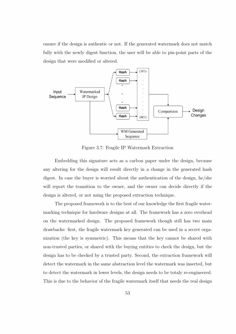
ensure if the design is authentic or not. If the generated watermark does not match
fully with the newly digest function, the user will be able to pin-point parts of the
design that were modified or altered.
Figure 3.7: Fragile IP Watermark Extraction
Embedding this signature acts as a carbon paper under the design, because
any altering for the design will result directly in a change in the generated hash
digest. In case the buyer is worried about the authentication of the design, he/she
will report the transition to the owner, and the owner can decide directly if the
design is altered, or not using the proposed extraction technique.
The proposed framework is to the best of our knowledge the first fragile water-
marking technique for hardware designs at all. The framework has a zero overhead
on the watermarked design. The proposed framework though still has two main
drawbacks: first, the fragile watermark key generated can be used in a secret orga-
nization (the key is symmetric). This means that the key cannot be shared with
non-trusted parties, or shared with the buying entities to check the design, but the
design has to be checked by a trusted party. Second, the extraction framework will
detect the watermark in the same abstraction level the watermark was inserted, but
to detect the watermark in lower levels, the design needs to be totaly re-engineered.
This is due to the behavior of the fragile watermark itself that needs the real design
53

to ensure that the output of the hash function is the same.
Fragile watermarks got mainly two main measures to ensure their soundness
and sensitivity. First, sensitivity to changes, and this is based on the sensitivity
of the hash function used. Second, the robustness of the embedded watermark, in
the sense that it cannot be deleted totaly from the design or changed to another
watermark without the key recognition. In our case, the fragile technique is based
on the coinciding transitions output mapping algorithm, and the sensitivity of hash
functions.
3.5 Discussion
In this chapter, we presented a robust watermarking framework that solves the
ghost/re-embedding problems inherited by the passive nature of the watermarking
technique. The approach is based on the utilization of coinciding transitions as well
as the unused transitions of the design FSM in order to give higher robustness. The
approach works in a public-key organization, where the detection key can be shared
with non-trusted parties. We have proposed two new insertion algorithms: the input
comparison algorithm, which has a low overhead on the design cycle, yet it has a
higher overhead on the produced design. And the output mapping algorithm, which
introduces higher embedded overhead, and lower overhead on the produced design.
Also, we have introduced an extraction algorithm to extract the robust watermark.
We have also proposed a fragile watermarking framework that protects the
design from intentional altering. The framework depends on the output mapping
algorithm, to insert and extract a fragile watermark in the design.
Currently both approaches work on flat FSMs, which is a practical drawback
for real designs. In Chapter 5, we present other techniques needed to handle hi-
erarchical designs. The proposed techniques depend on the same watermarking
techniques and algorithms presented here.
54

Chapter 4
Evaluation and Experimental
Results
In the last chapter, we developed different algorithms needed for IP watermarking.
In Chapter 2, we introduced a general evaluation criteria that can be used to evaluate
watermarking techniques. In this chapter, we will evaluate and perform an attack
analysis to ensure the robustness of our techniques, as well as a soundness proof that
our watermarking scheme does not affect design operation. We classify and describe
the overheads introduced to the system due to the watermarking process. Finally,
we describe the prototype of the watermarking tool, and show different modules
that we used to build the tool. We show how to generate an FSM from an HDL
design and watermark it. Finally, the implemented prototype is tested using the
benchmarks.
4.1 Impact on Design Functionality
In hardware design, designers cannot accept any change in system functionality.
Our watermarking technique should not interfere by any means with the original
operation of the system. To prove the soundness of the watermarking approach
55

the watermarked design automaton Mwm has to respect the same behavior of the
original automaton M . The soundness theorem is stated as follows:
Theorem 1: The watermarked design Mwm should behave exactly as the orig-
inal design M for any set of arbitrary inputs, under the condition that the extra
added bits ewm, used for watermarking, are set to the same logical level defined at
the watermarking stage.
Proof Let a be any arbitrary input sequence composed of m elements, such
that a = (a0, a1, ...am−1). awm is the same input sequence for the watermarked
design, where awm = 〈a, ewm〉, then:
∀ a ewm. ewm = C → (λ(q0, a) = λwm(q0wm, awm))
where C is a constant logical value of all extra added bits pre-defined at the time of
inserting the watermark, set to logical ’0’ in our algorithms, and q0wm is the initial
state of the watermarked design. To prove Theorem 1, under this condition, we need
to prove that, first, the initial state is the same in both designs; second, the output
functions (λ and λwm) will give the same values for any arbitrary input sequence.
The initial state might be changed in the watermarking process, but as long as
the extra bits are set to the pre-defined level, or ’0’ in our case, all the outputs of this
states will be the same for any given inputs. This implies that the two initial states
are equivalent under the condition ewm have the predefined values. This works in
the same manner in the case of the output function, where every transition in the
original design is still available and fully operating in the watermarked one. The
only difference is the extra input bits that is forced to have the value we chose in
order to prevent the state to take undesired transitions for such input. This implies
that the watermarked design will be operating in the same way as the original one
would do, i.e., our watermarking scheme is not causing deterioration to the original
design operation in anyway, nor adding any undesired behavior to the system as
long as the introduced test bits are set to the value chosen in the insertion level.
56

4.2 Attacks Analysis
Digital watermarking attacks are categorized in four main classes [16]: unauthorized
removal, unauthorized embedding, unauthorized detection, and system attacks. The
same categorization applies for IP watermarking schemes. System attacks aim at
attacking the concept of watermarking itself, as an example, attacking the crypto-
graphic base of the watermarking, or removing the chip that checks the watermark
physically in case of video for instance. This kind of attacks cannot to be avoided by
the watermarking schemes. Yet, the VISA IP protection group solves this by pro-
tecting the design through different transactions. On the other hand, unauthorized
detection poses a security threat for copyright protection techniques, as it does in
secret communications applications.
4.2.1 Removal Attacks
Coinciding transitions are considered a kind of supraliminal channels, attacking such
transitions or changing any of their values will directly result in destroying the design
under investigation. Removing one coinciding transition will affect the design under
investigation. Using this fact, the probability of watermark deletion is defined as the
“probability that any attack would change or delete the extra added transitions with-
out deleting at least one original transition”. This probability will change depending
on the way of watermark detection, as well as the usage of secret or public organi-
zations of our scheme. This probability will be calculated under the approximation
that all transitions and states have the same probability of occurrence.
In a masking attack, the intruder needs to delete one of the added transitions
to cover the ownership proof. In this case, the owner will not be able to detect
the watermark by dynamic means, i.e., by using the provided input sequence of the
watermark. This would work if the owner did not go to other levels of detection
like building the FSM again, or trying the detection algorithm proposed. We define
57

the watermark masking probability (Pm) as the “probability of deleting at least one
extra added transition without deleting any original one”, i.e. deleting one of the m1
extra transitions without deleting any of the originally existing n transitions.
This probability will differ depending on the operation mode. In the symmetric
(secret) operation mode, this probability will be related to the total number of design
transitions (n), because the intruder has to detect the extra transitions out of the
whole design provided. In this case P sm is equal to:
P sm =
m1
n + m1
In the above case, the attacker needs to choose one of the m1 transitions from
the new watermarked system Mwm. On the other hand, in the public-key organiza-
tion, the attacker does not need to choose from the n originally available transitions,
because the knowledge of the watermark key will limit the search from the whole
system to only the watermark transitions (both coinciding and added transitions).
This means that masking probability in this case P am will be the ”probability to delete
at least one added signature transition without deleting any coinciding ones. This
can be calculated as:
P am =
m1
m1 + m2
=m1
m
Deleting one transition of the added signature transition would mask the dy-
namic tracing techniques, but not deleting the whole watermark. The watermark
traces that exist in the system can be detected using static techniques. This means
that the intruder needs to delete most of the m1 extra transitions without delet-
ing any of the originally existing n transitions to delete the watermark. Thus, the
removal probability of the watermark (Pr) is defined as the “probability that any
attack would change or delete all the extra added transitions without deleting at least
one original transition”. Again this probability depends on the way of operation
(symmetric or asymmetric). In the symmetric mode, the intruder needs to choose
58

from n existing transitions, so that P sr is defined as:
P sr =
1
Cm1n+m1
where Cm1n+m1
is the combination of m1 and n + m1, such that Cm1n+m1
= (n + m1)×(n + m1 − 1)× (n + m1 − 2)× .... (n + 1).
In the above case, the attacker needs to choose m1 transitions from the new
watermarked system Mwm. On the other hand, in the public-key organization, the
intruder does not need to choose from the n originally available transitions, but
only from m watermarking transitions. This means that removal probability of the
watermark in the public technique (P ar ) will be calculated as follows:
P ar =
1
Cm2m
In our approach, the main measure of our approach capability to work in an
asymmetric (or public-key) mode is P ar or P a
m. Depending on such measure, the
system cannot work in the public mode unless these probabilities are smaller than
a certain value defined by the designer. One of the problems facing the intruder
will be the lack of knowledge of this probability, as well as the number of coinciding
transitions that might be there. The more coinciding transitions the system has,
the safer it is to operate in public-mode. It is worth to mention that a second secret
watermark can be added to the system in case the intruder could break the public
one. This will add some extra overhead on the system, but will be rewarded by a
higher level of security.
4.2.2 Embedding Attacks (Forging)
Embedding attacks aim at embedding another watermark in the design. As for
our scheme, we are proposing a third entity (an organization) that is responsible
for granting and authorizing the embedded signature (ownership certificate). This
signature should be time stamped as well. These two measures would directly stop
59

the ghost search attack, as the intruder will be forced to extract a 128 pre-defined
bits from the built system, that totaly coincide with his/her signature in order to
claim the ownership of the system. This is directly related to the probability of
finding false positives disused in the next subsection, which is very low. The other
technique to stop embedding attacks is the usage of a third entity, because the
time stamp will stop the intruder from re-embedding his watermark in a previously
licensed system, since the database of the third entity, as well as the time stamp
will show the real owner of the system.
4.3 Detecting False Positives: Probability of Co-
incidence
The Probability of Coincidence, is defined as a main measure of the authenticity
of the watermark, This probability is considered a measure for detecting the wa-
termark in a design by accident in a non-watermarked design (false positives). In
[64], the probability of coincidence (Pu) was defined as the “odds that an unintended
watermark is detected in a design”. It is also considered a measure for the ghost
attacks discussed above. This probability is calculated under the approximation
that all the transitions have the same probability of occurrence as:
Pu =1
[2|∆|]x − 1n ≥ 1
where x is the number of extra added transitions (the watermark in [64]) and | ∆ |is the total number of possible outputs. Using this formula, xmin, the minimum
number of extra transitions needed to satisfy a certain probability of coincidence Pu
is calculated as:
60

xmin =1
| ∆ | log2 | 1 +1
Pu
|
Although, we are only adding m1 extra transitions, we still need a sequence of
length m to detect the watermark in our case.
In case of using MD5 hash function with our approach, we are using a constant
number of bits for the watermarking sequence (128 bits). m is calculated as the
upper limit of the division of the number of added bits by the number of outputs,
i.e., m = d128|∆| e. We can then calculate the lower bound of the coinciding probability,
the worst achievable case, (Pu) as:
Pu =1
[2|∆|]d128|∆| e − 1
Hence,
Pu ' Pu =1
2128 − 1= 2.938× 10−39
In a real implementation, padding bits are added to the original 128 bit sig-
nature. We can safely state, that our probability of coincidence is nearly constant
and is larger than the above value for the 128 bits signature used. If the designer
needs a lower value for Pu, he/she can either change the hash function used with
one that provides more bits, or he/she can re-watermark the design using the same
technique again with a second signature.
4.4 Capacity: Area, Delay and Power Overhead
Our watermark approach depends on embedded signatures generated from hash
functions. In our particular case, the number of bits added by using MD5 hash
function is equal to 128 bits, this amount can be increased at the expense of the
number of input bits added, as well as the area and extra logic added to the system.
Mapping more coinciding transitions directly means that we will have less overhead
61

than the extra added ones, and that our system capacity is used more wisely. Over-
head is mainly divided into three different classes, area overhead, delay overhead,
and power overhead. These three measures give a clear measure for the synthesized
system before and after the watermarking process. We have measured the percent-
age of increase in the synthesized benchmark before and after the watermarking
approach, and these results are shown and discussed in the experimental results.
4.5 Experimental Results
To validate and test the performance of the watermarking algorithms, we have im-
plemented a prototype tool (Appemdix A) in C++ under Unix environment. Both
watermarking algorithm were applied on the IWLS93 [45] benchmark set using the
FSMs generated by the available SIS tool for evaluation purposes. The benchmark
generates one FSM for each design. Tables 4.1 and 4.2 describe the results ob-
tained on a Sun Sparc Ultra 5 machine with a 256 MHz Processor and 512 MB of
memory. All circuits were synthesized using Synopsys Design Analyzer using Cmo-
sis .5 technology as a target technology. Tables 4.1 and 4.2 show for each design,
the number of inputs/outputs, and transitions/states. The total number of added
transitions (m), coinciding transition (m1), extra added transitions (m2), and extra
inputs needed to add the watermark (ew) are also shown. C/NC in the tables define
if the design under investigation is completely specified (C), so at least one input
is needed, or not (NC). (N) represents the number of iterations needed, and (t) is
the time needed to insert the watermark in each design is given in ms. The time for
inserting the watermark is extremely short, hardly exceeded 8 seconds in the case
of SFC, for example, with 54 iterations involved (Table 4.1), which gives a good
indication about the low overhead the algorithm can introduce in the design cycle.
To evaluate the performance of the output mapping algorithm, Table 4.1 pro-
vides the removal probabilities (P sr and P a
r ) discussed earlier (for the output mapping
62

case), as well as the area, power, and delay overhead compared to the synthesized
original circuit. The experimental results demonstrate that our approach has a very
low effect on delay and power, especially when the design tend to get larger. On
the other hand, the area overhead is high for small designs, then decreases as the
designs get larger. This is due to the large signature size compared to the original
circuit. As for the robustness of the system, the algorithm failed to watermark some
designs efficiently, either it could not coincide transitions, such as for S1488, where
the watermarking cannot operate in public-mode. This can be solved by changing
the signature generated or re-watermark the design, but this will result in a higher
design overhead.
As for the the input mapping algorithm, Table 4.2 provides the same measures
discussed before. The experimental results demonstrate that the algorithm has a
smaller embedding time compared to the previous algorithm. This is mainly due
to the fact that the algorithm does not search the inputs, yet it tries to add the
watermark randomly. This results in adding more than one extra input in some
cases, such as TBK and SCF. This directly affects the area and power overhead of
the watermarked design and the overhead is not predictable even when designs get
larger. On the other hand, the the removal probabilities (P sr and P a
r ) are compa-
rable for both designs, but due to the fact of the extra randomness in the input
mapping algorithm, as well as the decreasing number of coinciding transitions, the
input mapping algorithm performs better when comparing the symmetric removal
property (P sr ), such as in the case of TBK.
We compared our approach to the algorithm based on unused transitions ap-
proach proposed in [64]. The authors, however, used the probability of coincidence
as the only measure for robustness, which only covered the false-positives case. We
had used the values generated by the authors in [64] to calculate both the masking
probability (P um) and the removal probability (P u
r ) for the IWLS93 [45] benchmark
63

Table 4.1: IWLS93 Benchmark Results (Output Mapping Algorithm)
Circuit ]I[O] ]T[S] C/NC m m1 m2 ew N t P sr P a
r Area% Power% Delay%
MC 3[5] 10[4] C 33 17 16 2 3 455 3.770e-12 8.570e-10 323 28.6 2.4
LION 2[1] 11[4] C 128 116 12 1 1 35 1.500e-17 4.214e-17 240 17.307 0
DK27 1[2] 14[7] C 64 48 16 2 1 85 5.814e-17 2.046e-15 153.2 19 3.6
EX4 6[9] 21[14] NC 26 13 13 0 6 416 E7.1084e-12 9.614e-8 29.3 23.4 5.8
OPUS 5[6] 22[10] NC 22 9 13 0 4 149 1.926e-11 2.010e-6 34.9 13.2 6.3
DK15 3[5] 32[4] C 34 21 13 1 3 146 4.890e-14 1.077e-9 92.8 17.2 1.8
S27 4[1] 34[6] C 128 125 3 1 1 133 1.4377e-6 2.929e-6 36.2 3.7 0
SSE 7[7] 56[16] C 19 6 13 1 5 214 1.268e-24 5.918e-15 29.2 14.2 2
S510 19[7] 77[47] NC 22 8 14 1 4 286 2.631e-17 3.127e-6 34.2 8.9 3.2
S1 8[6] 107[20] C 28 13 15 1 4 485 3.251e-20 2.671e-8 31.7 14.8 3.4
PLANET 7[19] 115[48] C 9 4 5 1 17 829 4.441e-9 0.0079 36.2 12.4 0.9
EX1 9[19] 138[20] NC 8 3 5 1 17 1001 1.938e-9 0.0178 17.391 14.516 3.5
STYR 9[10] 166[30] C 15 7 8 1 8 566 4.094e-14 1.554e-4 13.4 15.4 1.8
SCF 27[56] 166[121] NC 3 0 3 0 51 8021 1.265e-6 1 3.5 9.8 1.4
KIRKMAN 12[6] 370[16] NC 22 11 11 0 10 201 1.369e-21 1.417e-6 2.1 1.6 0.5
S298 3[6] 1096[218] C 22 3 19 1 4 154 1.436e-41 6.493e-4 5.4 5.8 0.7
TBK 6[3] 1569[32] C 43 18 25 1 1 144 1.223e-55 1.643e-12 1.7 3.2 0.2
set shown in Table 4.3. Considering all transitions have equal occurrence probabil-
ities, the masking probability (P um) can be calculated as the “probability that any
attack would delete at least one transition in order to cover the watermark with-
out affecting any of the original design transitions”. Hence, P um was calculated as
follows:
P um =
nmin
n + nmin
Furthermore, the removal probability (P ur ) is calculated as the “probability that any
64

Table 4.2: IWLS93 Benchmark Results (Input Comparison Algorithm)
Circuit ]I[O] ]T[S] C/NC m m1 m2 ew t P sr P a
r Area% Power% Delay%
S27 4[1] 6[34] C 128 19 109 1 34ms 8.4e-15 4.5e-23 212.5 93.2 24
BBARA 4[2] 10[60] C 65 20 45 2 15ms 2.8e-19 5.8e-9 353 74.4 92.2
STYR 9[10] 30[166] C 13 12 1 2 15ms 6.9e-19 7.6e-2 49 14.5 12.8
BBSSE 7[7] 16[56] C 19 17 2 2 9ms 5.6e-17 5.8e-3 97 36.8 32.2
CSE 7[7] 16[91] C 19 17 2 2 10ms 3.6e-20 5.8e-3 86.5 21.5 11.4
SSE 7[7] 16[56] C 19 17 2 2 10ms 5.6e-17 5.8e-3 - - -
SCF 27[56] 121[166] C 3 3 0 1 54ms 1.2e-6 1 19.5 16.2 38.4
S420 19[2] 18[137] C 65 43 22 2 33ms 1.5e-42 8.2e-18 115 51.9 56.5
TBK 6[3] 32[1569] C 43 37 6 2 51ms 5.1e-76 1.6e-7 58.3 13.5 38.1
attack would delete all added watermark transitions without affecting any of the
original design transitions”. Hence, P ur can be calculated as follows:
P ur =
1
Cnminn+nmin
where Cnminn+nmin
is the combination of nmin and n + nmin.
The measures provided in Tables shows how vulnerable the algorithm is for
masking attacks. Masking attacks do not delete the whole watermark, yet they cover
the authorship information, which means that the direct detection method proposed
by the authors is not reliable enough, and exhaustive search or the Genome search
[64] will be the main watermark extraction method. Besides, the removal probability
(P sr ), although higher, is not high enough in some cases to consider the system totaly
secure, such as the case of SCF (Table 4.3). On the other hand, the overhead starts
high as expected with small designs, yet it becomes negligible when designs get
larger. The only problem in this is that the authors did not rely on a fixed length
signature, which would raise questions about the amount of information embedded
65

Table 4.3: IWLS93 Benchmark Results using Unused Transitions Algorithm
Circuit ]I[O] ]T[S] (I/O)wm nmin Pu P um P u
r Area%
S27 4[1] 34[6] 1/3 9 1.4e-11 0.2 1.4e-9 143
BBARA 4[2] 60[10] 1/1 10 9.3e-10 0.14 2.2e-12 74
DK14 3[5] 56[7] 1/0 7 2.9e-11 .095 1.8e-9 24
EX1 9[19] 138[20] 0/0 4 1.3e-23 0.028 6.7e-8 3.2
EX1 9[19] 138[20] 0/0 2 3.6e-12 0.014 1.02e-4 0.6
STYR 9[10] 166[30] 1/0 4 9.1e-13 0.023 2.9e-8 22
SCF 27[56] 166[121] 0/0 2 1.9e-34 0.011 7.1e-5 0.2
especially in the large designs, for instance embedding only 40 bits in STYR (Table
4.3).
It is worth mentioning that for all designs, the probability of coincidence Pu
is nearly constant and less than 2× 10−39. The output mapping algorithm increases
the probabilities for both cases, with contrast to the input comparison algorithm
where Pc depends only on coincidence. One more point worth to be mentioned is
that increasing the coinciding transitions (m2) will directly increase the robustness
of the system in the public-key case, yet it lowers the robustness of the system in
the secret-key mode. It is clear that the overhead decreases in this case as we tend
to increase the number of coinciding transitions, but the overhead is more than
expected for such designs. In fact, both algorithms tend to add new inputs even if
it is not extremely needed. Also, the amount of coinciding transitions decreases fast
with increasing the number of outputs. We believe these are the main reasons that
add a high overhead on the synthesized design.
Table 4.4 shows the results generated for the fragile algorithm using the same
measures discussed before. In this case, we used the MD5 hash function to generate
the fragile signature of each design. We did not divide the design into windows, but
66

Table 4.4: IWLS93 Benchmark Results (Fragile Watermarking Algorithm)
Circuit ]I[O] ]T[S] C/NC N t
MC 3[5] 10[4] C 1 234
LION 2[1] 11[4] C 1 152
DK27 1[2] 14[7] C 3 234
EX4 6[9] 21[14] NC 1 346
OPUS 5[6] 22[10] NC 4 545
DK15 3[5] 32[4] C 1 138
S27 4[1] 34[6] C 2 127
SSE 7[7] 56[16] C 2 231
BBARA 4[2] 60[10] C 1 346
S510 19[7] 77[47] NC 1 282
S1 8[6] 107[20] C 1 326
PLANET 7[19] 115[48] C 1 248
EX1 9[19] 138[20] NC 20 8255(F)
STYR 9[10] 166[30] C 2 363
SCF 27[56] 166[121] NC 3 1065
KIRKMAN 12[6] 370[16] NC 2 354
S298 3[6] 1096[218] C 1 239
TBK 6[3] 1569[32] C 1 284
we hashed the whole design to generate one single global fragile signature. The table
shows that we could insert the fragile watermark in all designs with zero overhead,
and in a very low time, except in the case of EX1 because most of its outputs are
zeros which made it hard to insert the signature.
67

Chapter 5
Watermarking Modular HDL
Designs
In the previous chapters, we have introduced and developed different techniques
to watermark FSMs. Only flat FSM are however considered, i.e., the IP design
has to be flattened into a single large FSM, which is a non-negligible drawback.
In this chapter, we address watermarking of hierarchical and modular designs. It
should be noticed that the word hierarchical design here is used in the sense of using
different design components yet still sticking to the same RT level like the previous
section. Next, we propose an algorithm for hierarchical FSM (HFSM) watermarking.
We then present techniques developed for both modular and communicating FSMs
watermarking, as well as concurrent designs and models. In this chapter, we are
not introducing new watermarking algorithms, but we developed techniques that
integrate the previous algorithms in the design path with minimal overhead to the
design cycle.
68

5.1 Problem Description
A very common style of hardware architecture design is the datapath controller
model [71] (Figure 5.1). The design is treated as two separate pathes, where the
data section includes loadable registers, arithmetic and logic functions. On the other
hand, the control modules include any random logic and state machines needed to
control the datapath. Usually, as the design gets larger, we tend to divide both
data and control pathes into many modules, these modules are communicating to
transfer status and data. The control module contains different communicating state
machines as shown in Figure 5.1.
Controller Controller
Registers Data Path Registers Data Path
control controlresults results
status statusmode
data output
data
Figure 5.1: Datapath Controller Architecture
The distinction between data and control is useful when it comes to machine
execution. Yet, such methodology introduces many challenges for any watermarking
technique as described next.
• Module Embedding and Hierarchy: As discussed earlier, hardware de-
signs are composed of many communicating modules. Moreover, these mod-
ules are hierarchical in nature, i.e., each module embeds one or more modules
inside and with different levels of abstraction, such as module H in Figure
5.2. These modules have different depths and different complexities in the
same design. Finally, not every module can be watermarked by our technique.
Our algorithms target the FSM parts of the design, but the design contains
69

a datapath as well as the control path, which is usually the control path is
the path that have FSMs and can be watermarked by our technique. In more
formal words, Hierarchy [42] is defined as the “interaction between a module
and the refining components in that module”.
• Design Parallelism: The exponential increase of the number of transistors
enabled a similar increase in design functionality and added options. This
results in high parallel designs (such as the X,Y,and Z pathes shown in Figure
5.2). Although these pathes are highly parallel, they still communicate and
have feedback loops with different interaction behaviors discussed below.
• Concurrency and Interaction: Different modules communicate and inter-
act using different concurrency models discussed before, for instance modules
B and C in Figure 5.2. Each treats the FSM and its reaction in a different
way. Concurrency was investigated and defined in many different ways. In
this work, we define Concurrency [42] as the “interaction between multiple
simultaneous components and modules”. This definition is the one introduced
in [24] by Girault et al.. In [42], the authors showed how to embed hierarchi-
cal FSMs into different concurrency models, including dataflow (DF), discrete
events (DE), and the synchronous/reactive (SR) models discussed below.
• Module Visibility: Finally, another challenge that will face the watermark-
ing process is module visibility. Some design modules, such as B and E in
Figure 5.2, will not be visible from outside. Extracting the watermark from
such modules will be very complicated, and will need re-engineering in many
cases. This challenge cannot be solved by any watermarking technique, except
if we depend on design for testability (DFT) concepts, which ensure that most
of the design main modules can be visible to test procedures.
70

X
B
Y
Z
A C
D E F
G H
Figure 5.2: Generic Hardware Design
5.2 IP Watermarking Framework
The first problem that will face the watermarking technique proposed in this thesis
is to divide the design into datapath and control path. This cannot be done auto-
matically in most cases. A first solution would be to flattened the whole design into
one large FSM and watermark it. Yet, this solution cannot always be realized in real
life. First, because the IP designs are very big and this will result in state-space-
explosion and a failure to generate the full FSM needed. Second, the watermarking
process is a complementary process, which should not result in modifications of the
71

original design, and flattening the design will result in lowering the design compet-
itiveness, business wise, especially if the design will be sold at the same level of the
watermarking. Besides, the modular design cannot be re-generated from the flat
FSM, which will make the design harder to manage, and simulate.
As proposed in the previous chapter, we have two types of embedded water-
marks, either we are trying to embed a robust watermark, for copyright protection
reasons, or a fragile one, for protection against tampering.
Fragile watermark is easier to embed, because we need to divide the design into
modules or parts as we discussed in Chapter 3. Besides, embedding such watermark
does not affect the design nature. Finally, the fragile watermark is detectable only at
the same design level, so we do not need to take care of any visibility problems that
might arise because we already have the whole design. Embedding fragile watermark
is quite simple. The designer will have to decide first, if he/she prefers to insert a
global watermark or just a local one. The global watermark is fragile watermark for
the whole system. So, the designer, will insert the watermark into different modules
of the design after hashing it. This global watermark will ensure the whole design
integrity but will not ensure each block’s integrity. This is because we will have to
hash larger blocks, which will decrease the sensitivity of the watermark to point to
the exact modified part in the block. We can hash and watermark each block alone
as well in a local process, treating the FSMs exactly as the non-communicating ones
discussed earlier.
On the other hand, robust watermarking is a more complicated process. After
dividing the design into control path, and data path. We assign the control part
of the design to the watermarking process. Then, we specify parallel pathes of
the design, like the paths X, Y, and Z shown in Figure 5.2. We also identify the
communicating and non-communicating pathes, as this affects the watermarking
process afterwards. Finally, we extract all visible modules from the design, or the
modules we can directly detect and compare their outputs.
72

We convert all communicating pathes to non-communicating pathes. This can
be done by relying on parts of the modules output, and ignoring the communicating
ones. A constant value is assigned for each of these pathes in the case of watermark
extraction. This will result into separate design pathes.
Different paths of the design is watermarked after dividing the watermark
sequence on different paths, as well as, different modules in the path. If the design
has enough visible modules, we concentrate on watermarking these parts only. In
this favorable case, the watermark will be detectable at all lower design levels. Yet,
if the design does not have enough visible modules, we will watermark internal
modules as well, using the algorithm shown below. Dividing the watermark among
the paths and per module is done through iterations to ensure the highest robustness
and the lowest overhead possible.
5.3 Multiple Module Watermarking
Hardware designs are often designed in a hierarchal way (Figure 5.3 [24]), where
the main system design is defined in one large block (block A in the figure) that is
defined in terms of sub-blocks described by smaller blocks, and so on, until we reach
the complete description of the system. FSMs are nested inside other modules, and
moreover, each FSM state can be described as a set of modules, which makes it
harder to flatten and describe.
5.3.1 Interactive Module Watermarking
In this section, we propose a technique for watermarking multiple modules designs.
Figure 5.4 shows a typical path of any of the parallel pathes of the FSMs. We have
simplified this model, by not considering backward communications in the design.
The case of backward communication is considered in the following section, as it is
linked to concurrency models. Inside each of the modules in Figure 5.4 is either, a
73

������������
������������������������
������������������������
������������������������
������������������������ ������
������������������
������������������������
������������������������������
������������������������������
A
������
������
��������
������������
������������
Figure 5.3: Hierarchical Nesting of FSMs with Concurrency Models [24]
simple direct FSM, or one level deep HFSM.
Figure 5.4 shows an example of such modular watermarking process. The
design is composed of four modules. As shown in Figure 5.4, the outputs of module
D can be accessed directly. These outputs are needed to extract the whole design
in lower levels. But, watermarking only module D alters the design security in most
cases, because changing one design module will cover the whole watermark. We can
rely on watermarking the last module in each path, if we have enough pathes to
ensure the level of security needed, else we will have to divide the watermark on the
whole control path to ensure higher robustness. The best solution for this problem
is to add two watermarks, the first using only the last module in each path, an it
74

will be easy to extract in case of direct extraction, and the second divided among
the whole design in the case the first watermark is tampered or masked.
We use both algorithms proposed in Chapter 3 to watermark the whole design
path. Yet, instead of generating random inputs for the whole design, we will use
the outputs of each module (a part of the signature) as the input of the next stage.
This can be done as follows:
1. In Figure 5.4, we use the output mapping algorithm to insert the first part of
the signature in module A.
2. Using the input comparison algorithm , we embed the signature generated
from module A, as an input signature used in module B. This forces module
B to generate another part of the intended design needed.
3. We use the above process until we watermark all modules under investigation.
On the other hand, this is only a part of the signature, as other parts will be
embedded on similar pathes in a similar manner. Combining the output of each
module with the input of the next module will result in minimizing the added tran-
sitions. This is essential as the input comparison algorithm tends to add extra
overhead of the design. Another advantage of this process is extracting the wa-
termark in a smaller number of input sequence. As this sequence generates the
watermark embedded in the whole path.
In the example of Figure 5.4, we start by using the output mapping algorithm
to watermark the first design module A. The (11) output will be embedded in the
module A and generate the (101) input sequence. The output of module A will
be considered as the input of the watermark used in module B. This means that
module B will be watermarked using the (11/010) transition that coincides in this
case using the input comparison algorithm. We will do the same for modules C and
D where we insert (010/11) and (11/00), respectively.
75

Signature Added = [11 010 111 0]
001/11
111/00
S9 S10
000/001 001/011
101/010
111/000
010/111
S8
S7
S6
S5
B DCA
S2
S1 001/11
101/10
000/01
S0
S4S3
11/010
01/11
01/10
Figure 5.4: Modular Watermarking Example
The above algorithm watermarks forward pathes, for a backward path (feed-
back reaction), extra modifications need to be made as discussed in the next section.
5.4 Concurrent Module Watermarking
In our work, we depend on *charts (pronounced “starcharts’;) introduced in [24] by
Girault et al. *charts decouples the concurrency model from the hierarchical FSM
semantics. In the next subsections, we will describe the main *chart concurrency
models and their usages in the hardware design process.
Figure 5.5 shows a simple situation of embedding communicating FSMs into
different concurrency models. These models can be either dataflow (DF), discrete
events (DE), or synchronous/reactive (SR). In the next subsections, we will describe
these models then show ways embed the watermark in each of these models.
76

a
v
y
x
u
b/u
b
a/v
v/y
u/xA
B
���������
���������
���������
���������
Figure 5.5: Concurrency Model of Two Embedded FSMs [43]
Lee et al. [43] described problems that might arise due to the usage zero-path
delay in the above concurrency models. Due to such problem, Lee proposed not
to use zero-path delay loops whenever we got a feedback between two concurrent
blocks. Depending on such assumption, we utilize the added one clock delayed
inputs to provide the inputs of the watermark. For instance, in the case of Figure
5.5, we will start by watermarking module A, this is done by embedding a part of
the whole watermark using the same algorithm used for regular FSM. The generated
input sequence by this process is divided into two parts: the first part is directly
provided to the module as input a and the second is feed from the next stage u .
Input u will be considered as part of the generated watermark of the next stage, this
means that we consider the generated watermark output for module B composed of
u and y. This will be done exactly with module A again with outputs x and v until
the whole signature is embedded. The above technique will be discussed in more
details in the example provided in the end of the section.
77

5.4.1 Watermarking Synchronous/Reactive Models
An SR system [43] is a set of blocks instantaneously communicating through un-
buffered directed arcs. The execution of the system occurs at a sequence of discrete
instants. To ensure that the system is deterministic, i.e., always finding the same
behavior given the same inputs, a partial order relation is imposed on the arc values
that is augmented with a bottom value. Most familiar functions are strict functions
that are always monotonic. However, a directed loop of all strict functions always
causes causality problem.
SR is synchronous in the same sense as synchronous digital circuits. Time
delays in computations become irrelevant, so a useful conceptual gimmick is to
assume that computations take zero time. SR has a major advantage over DE in
that an SR model can be compiled into either sequential code or parallel circuits.
DE, in contrast, is difficult to implement efficiently in sequential code, although it is
used routinely to specify circuits, which are intrinsically parallel (e.g., using VHDL
and Verilog languages) [24]. The execution of an SR system occurs at a sequence of
global, discrete, instants called ticks (as in ticks of a clock) [24]. At each tick, each
signal either has no event (is absent) or has an event (is present, possibly with a
value).
Considering at a tick the inputs to the FSM are known, then the FSM can
react to them and possibly assert output events. Any output events that are not
asserted would then be known to be absent. However, there are two difficulties
with SR [24]: first, the current state of the FSM may refine to an SR or non-SR
subsystem. Second, the inputs may not be completely known. In particular, if the
SR system includes a directed loop, then the inputs cannot be known at the start
of the tick for all the modules in the loop.
We have limited these systems so that we do not face the main problems faced
by SR models. First, we allow only FSM, and one level deep HFSMs to be embedded
inside an SR block. This is done to ensure that the FSM will generate an output
78

every single clock tick. Second, the watermarking tool only accepts SD models which
its inputs are completely known, at the time of execution, as of course we cannot
predict the missing inputs.
SR [43] is well-suited to resource management and control logic, but over-
specifies numerical computational systems by imposing synchrony.
5.4.2 Watermarking Discrete Events Models
The DE model [43] carries a notion of global time that is known simultaneously
throughout the system. An event occurs at a point in time. In a simulation of such
a system, each event needs to carry a time stamp that indicates the time at which
the event occurs. The DE simulator needs to maintain a global event queue that
sorts the events by their time stamps. It defines the current time of the system to
be the smallest time stamp in the event queue.
An FSM embedded inside a DE block performs one reaction when the DE
block fires. Lee [43] chose to consider the FSM to appear as a zero delay block in
the DE, i.e., the event passed to a DE system in a reaction of the FSM is assigned
the same time stamp as the input event that triggers that reaction.
DE is well-suited to modelling hardware systems, but poorly suited to more
abstract specifications because of its physical notion of time.
5.4.3 Watermarking Synchronous Dataflow Models
The Synchronous Dataflow (SDF) system is usually composed of a set of blocks
interconnected directly [42]. Each block represents computational functions that
map input data into output data when they are executed. The links represent
streams of data tokens, and can be implemented as first-in-first-out queues. The
block consumes a fixed number of tokens from each input and produces a fixed
number of tokens on each output.
79

When an FSM describes a block of an SDF graph, it must externally obey
SDF semantics. An SDF systems is based on queues where each block produces and
consumes a fixed number of tokens from each input and output. The execution of the
SDF block is related to one reaction of the embedded FSM, hence we will consider
all the tokens as one input of the FSM. In this case, the FSM will be watermarked
exactly like any multiple module path discussed above, where each single block will
use the tokens provided to generate one of the watermark outputs. These outputs
are then consumed with the next module to generate the next watermark outputs
as discussed above.
In the case of DF, deadlock might occur in Figure 5.5 in the case that each
module is waiting for a token from the other module, i.e. A waiting or u, and B
waiting for v. According to [44], this can be avoided by adding one unit delay (an
initial token) in the loop, allowing one FSM to fire first. This will add a notation of
delayed semantics to the design, yet it will solve the deadlock problem.
DF is well suited to numerical computation [42], such as signal processing, but
poorly suited to resource management and control logic.
5.4.4 Multiple Module Watermarking: Example
The Reflex Game [4] is a commonly used example for control-intensive designs. In
this example, we use a sub-block of the game because this block contains direct
feedback loop between two modules. The reflex game is a two-player game (Fig-
ure 5.6), the inputs to our system are ready, go, stop and time, and the outputs
are yellowli, greenli, exit, and error used to control a user interface. Normal play
proceeds as follows: 1) When player 1 is ready, he presses ready, and the status
light turns yellow. 2) Player 2 presses go, the status light turns green and player 1
presses stop as fast as he can. 3) The game ends and the end light is generated. 4)
The game measures the reflexes of player 1 by reporting the time between greenli
and end in later stages. There are some situations where errors might occur, and
80

an error signal is generated. These are as follows. a) Player 1 presses stop before
or at the same instant that player 2 presses go. b) After player 2 presses go, player
1 does not press stop within time units. One additional rule is that if player 2 does
not press go within time units after player 1 presses ready.
The system originally is built of 4 levels, we are using level 3 which is an SR
model consisting of the two players. These are interconnected with a zero-delay
feedback loop, so we exploit the semantics of SR. At level 4, the two players are
refined into concurrent FSMs. Player 1 starts in the idle state, and when ready is
asserted, emits a start event and transitions to the wait go state. This causes player
2 to transition to the wait state and emit a yellowli event. In several states, we
need to count ticks from the clock to watch for time outs. This counting is a simple
arithmetic computation that can be performed using the DF graph shown at level
(5) and we consider such a level to be with zero-delay as well, so it will not affect
our technique.
Watermarking such design is faced with the direct feedback loop as shown in
Figure 5.6. Starting form any random state (state (wait go) in our case), we add a
new transition to the design. This transition uses inputs ready and stop to add the
(111) signature on the error, exit, and greenli. This input generates the start signal
as well to start watermarking the other Player 2 module. In the Player 2 module,
yellowli is generated, coinciding with the already available transition, we will add
the !end (not end) output signal as well to this transition. Using the !end∧
!ready∧
stop inputs in the Idle state adds the second part of the signature using the same
technique as before. This adds the (101) part to the design, and will generate the
start signal that will be used in the Player 2 module. The Player 2 uses the start
and go signals to add one more transition that embeds the (0) to the design on the
yellowli and end to Player 1. Finally, the last (1) is embedded on the last added
transition after padding it with two zeros.???
81

comparetime timeo
,!end
go \/ timeo/end
start /\ go /start
/!yellowli, end
/error /greenliend /\ !stop
ready/\ !
wait
delay
constant
add
yellowli
Idle
time
go
start/
yellowli
Player 1
error
/error
Watermark Added in the Second Module = {1, 0}Watermark Added in the First Module = {111, 101, 1}
greenli, start/error,!end /\! ready /\ stop
/errorend /\ ready
/errortimeo
ready /\ stop
/exitstop
greenli, start/error, exit,
stop
done
go
stopwait
waitreadywait
timeo
timeo
ready exit
start
greenli
time
stop
end
start
endPlayer 2
Figure 5.6: Watermarked Reflex Game Example
5.5 Watermarking HFSM Models
5.5.1 Finite State Machines Extension
For truly finite state systems, the environment must be finite state as well (e.g., it
could be defined as another finite state machine). If this requirement is dropped,
we obtain the well-known Turing Machine model [27]. Most practical systems have
a very large number of states and transitions which is considered a major weakness
for the basic FSM. Representation and analysis become difficult. Harel introduced
that Statecharts model [26] as the first technique for hierarchal description of FSMs
(HFSMs), or what is refereed to by hierarchical concurrent FSMs (HCFSMs). Since
then a large number of models and variations have been introduced by many people,
82

Von Der Beeck [66] describes and compared between these models.
Girault et al. [24] focused on deterministic and reactive FSMs. An FSM is
deterministic [42] if from any state there exists at most one triggered transition for
the input events. An FSM is reactive [42] if from any state there exists at least one
triggered transition for the input events. Mainly these models are used by Ptolemy
[5], a software environment that supports heterogeneous system design by allowing
diverse models of computation to coexist and interact. Girault focused in both
embedding FSMs into these concurrency models, as well as embedding these models
in HFSMs.
State3
State1Idle
a ^ ! b /v
!a ^ b/y
State2
a /v
b/v
Figure 5.7: An Example of an HFSM
In an HFSM, a state may be further refined into another FSM. Figure 5.7
shows an example of an HFSM machine. The inside FSM is usually called the slave
and the outside FSM the master. If the state can be refined, it is called hierarchical
state like state State1 in Figure 5.7, else it is called an atomic state (Idle in the
case of Figure 5.7). The input alphabet for the slave FSM is defined to be a subset of
the input alphabet of its master FSM, a, and b in Figure 5.7. Similarly, the output
signals from the slave FSM are a subset of the output signals from its master. Also,
the slave FSMs react relative to the reaction of their master FSM. Girault et al.
[24] defines one reaction of the hierarchical FSM as follows: if the current state is
not refined, the hierarchical FSM behaves just like a basic FSM. If the current state
is refined, then first the corresponding slave FSM reacts and then the master FSM
83

reacts. Thus, two transitions are triggered, so two actions are taken. These two
actions must be somehow merged into one.
Hierarchy adds nothing to the model of computation. Nor does it reduce the
number of states, but it can significantly reduce the number of transitions and make
the FSM more intuitive and easy to understand, helping the designer to solve the
state-space-explosion problem he/she might face.
5.5.2 HFSM Watermarking
The input alphabet for the slave FSM is defined to be a subset of the input alphabet
of its master FSM. The output signals from the slave FSM are a subset of the output
signals from its master. Also, the slave FSMs react relative to the reaction of its
master FSM.
The slave FSM usually has one entry point, and one or more exit points. We
propose to watermark such designs using the following algorithm (Figure 5.8)
1. Starting from any randomly chosen state Sx, check if this state is atomic or
hierarchical.
2. In case of atomic state, compare the outputs of the state Sx to the generated
signature to check if they coincide.
3. In case one of the outputs is equal to the watermark bits, this transition will
be considered part of our watermark. The next state will be decided according
to the transition used.
4. If the signature sequence is not equal to any of the outputs, then the inputs of
Sx will be checked to determine if there is any free input that can be used to
add an extra transition. The next state in this case will be chosen randomly,
with preference given to states with free transitions.
84

5. If state Sy is a hierarchical state, the entry point of the slave FSM is considered
the newly reached state.
6. Compare the outputs of the state Sy to the generated signature to check if
they coincide.
7. In case one of the outputs is equal to the watermark bits, this transition will
be considered part of our watermark. The next state will be decided according
to the transition used. In this case, the newly reached state is either an exit
point or, just another state in the slave FSM.
8. If the reached state is not an exit point of the slave HFSM, the master state
will be forced to stay in the same state by using the self loop transition. Only
a part of the output, the slave part, will be considered part of our watermark.
9. If the reached state is an exit point of the slave HFSM, the master state will
be considered an atomic state. Sy outputs will be compared to the watermark
outputs exists, and either a coinciding or an added state will be used according
to the algorithm.
10. The algorithm will loop until the embedding of all the signature bits is done.
5.5.3 Watermarking HFSM: Example
Figure 5.9 illustrates an example for the above algorithm using the signature given
at the bottom of the figure. Starting from an atomic state S0 (Figure 5.9(a)), we
find a coinciding output (0010) and move to S2. S2 is a hierarchical state, so we will
use the entry point of such FSM (ent) as our new state. In Figure 5.9(b), output
(11) does not exist but input (00) is free. The next state in this case will be decided
randomly and the algorithm advances to state s2. State s2 is not an exit point for
the slave FSM, so S3 will be forced to use the inputs (10) as the self loop input, and
state s2 will still be considered our reached state. Only the first part of the output
85

Force Self Loop?
Reach Exit Point?
Still Available?Extra I/P Bit
Add Extra I/P Bit
YesO/P Coincide?
Add Extra Transition
No
No
No
Consider Slave Entry as State Reached No
Atomic State?
START
No
Extra I/P BitStill Available?
State I/P Free?Yes
Yes
Yes
END
Yes
Add Extra I/P Bit
Yes
YesState I/P Free?
YesO/P Coincide?
Finsihed Sign. Bits?
Add Extra Transition
Yes
No
No
No
No
Figure 5.8: Watermarking HFSM Algorithm
is considered a part of our watermark in this case. In s2 (Figure 5.9(c)), the output
coincides with (01), hence the next reached state is s1, which is an exit state. The
output (11) is found not to coincide with any of the outputs of state S3, but the
input (10) can be used to embed such output, and it will drive us randomly to state
S1 as shown in Figure 5.9(d). This will generate a fully watermarked design using
the input sequence shown below.
86

5.6 Discussion
In this chapter, we extended the previously proposed watermarking framework to
embed the watermark in modular designs. We started by showing the distinction
between data and control parts of the design, and discussed the problems that would
arise from trying to watermark any modular design.
We presented changes needed in the fragile watermarking approach, and how
a modular design can be watermarked in the case of fragile watermarking. On the
other hand for robust watermarking, more problems arose. We have divided these
problems to visibility, parallelism and concurrency. Parallelism is not a big problem
as it gives higher visibility of the design, and so helps to watermark the design
more effectively. On the other hand, we used the two algorithms proposed before
to watermark designs with multiple modules. We concentrate on the concurrency
models, and showed how we can watermark FSMs embedded into another concurrent
module such as DE and SR models. Finally, we have introduced a technique for
watermarking a special case of HFSMs. The algorithm is based on the output
mapping algorithm presented earlier.
The proposed solutions, help embed the watermark in modular designs, ensur-
ing that our watermarking technique does not have high implementation overhead.
This would help the integration of the watermarking process in the design cycle. Yet,
one of the main problems with this technique is the loss of the ability to extract the
watermark easily at the lower levels in most of the cases, as well as it cannot be
fully automated.
87

S1
S2´
1011/000110XX/00YY
1101/0011
s1
0101/1111
ent s210/11
11/0101/11
S0
(a) (b)
00/11
(c)
00/11
S0 S1
S2´
1011/000110XX/00YY
1101/0011
0101/1111
ent
s1
s210/11
11/0101/11
S0
1011/0001
1101/0011
0101/1111
ent
s1
s210/11
11/0101/11
11XX/01YY
11XX/01YY
11XX/01YY
0111/1101
(d)
Signature Sequence Actually Added = [(1011/0001),(1000/0011),(1101/1101)] Signature Sequence to be Added = [0001111101]
10XX/00YY
S1
S2´
10XX/00YY
1101/0011
0101/1111
ent
s1
s210/11
11/0101/11
11XX/01YY
S0 S1
S2´
1011/0001
Figure 5.9: Watermarking HFSM: Example
88

Chapter 6
Conclusions and Future Work
6.1 Conclusions
In this work, we proposed, analyzed, and evaluated novel approaches for watermark-
ing sequential IP designs. The approach is based on the utilization of coinciding
transitions as well as unused transitions in order to give higher robustness. Using
this approach, we proposed related frameworks for both robust and fragile water-
marking. While the robust technique is used for copyright protection of the design,
fragile watermarking secures the design against tampering and protects customer
and owner rights. We integrated both techniques to offer a complete framework
for copyright protection. We defined the main requirements for any IP watermark-
ing technique. We believe the proposed watermarking approach satisfied the main
watermarking requirements defined in Chapter 1:
1. Does not rely on the secrecy of the algorithm: The proposed approach
and algorithms can be made public without posing extra threat to the water-
marked design.
2. Embeds enough data to identify the owner of the system: In case of
the robust watermarking, the approach embeds 128 bits of hashed data (using
89

MD5), which is large enough to act as an ownership proof. This was made
clear using the probability of coincidence used for finding false positives (Pu).
3. Robustness: The proposed approach was evaluated and proven (using ex-
perimental results) to have high robustness due to the usage of actual parts of
the design as part of the watermark.
4. Asymmetry: Our approach can be used publicly without the fear of deleting
the watermark.
5. Has a low implementation overhead: Using coinciding transitions de-
creases the introduced design overhead, while it increases the robustness of
the design.
6. Detection and tracking tools: Masking attacks can prevent direct dynamic
methods from finding the embedded watermark. A watermark detection (ex-
traction) algorithm based on coinciding transitions was proposed.
7. Integration into design path and handling larger designs: The pro-
posed techniques to watermark communicating FSMs, as well as HFSMs, en-
abled the watermarking process to be integrated in the design path.
The proposed algorithms were evaluated using different attack and perfor-
mance measures and tested through experimental results. We evaluated the sound-
ness of the approach and proved it mathematically. Results showed that robust
algorithms can be used as a public-key watermarking scheme in most of the designs.
The algorithms are fast and have a comparatively low overhead on the design cycle.
6.2 Future Work
The methodology proposed in this thesis is a new technique that offers a realistic
secure and robust watermarking for IP designs. Furthermore, it presents a first step
90

towards combining both concurrency and watermarking techniques. Based on our
previous work in this domain, we believe that the proceeding future work can be
completed and expanded in the following manner:
• Algorithm Optimization: The proposed algorithms, especially for the mod-
ular watermarking techniques, need to be further optimized. One of its draw-
back in the case of communicating FSMs, is its interactive nature, which will
give a higher overhead for the designer to watermark the design. We believe
that a prototype tool needs to be built for these algorithms, and tested further
on real designs, trying to fully automate this approach.
• Detection and tracking tools: Masking attacks can prevent direct dynamic
methods from finding the embedded watermark. A watermark detection (ex-
traction) algorithm based on coinciding transitions was proposed in this thesis,
but even in the availability of the coinciding transitions in the design, ex-
tracting all the traces of the watermark in the shortest time, using minimum
inputs, and without rebuilding the whole FSM is considered an NP-hard prob-
lem. Searching algorithms were developed to solve such problems in different
applications, including graph theory [15] and the Genome approach [64]. We
propose to use one of the available algorithms to optimize the search procedure
for extracting the watermark. Putting into consideration that the extraction
phase should be done without rebuilding the FSM, i.e., in HDL code or lower
levels. This will result in the integration of a simple simulation tool to extract
the signature traces directly. We believe that further investigation of these
techniques that can help solving such problems.
Finally, IP watermarking techniques are still in their infancy. It is considered
a new field with many directions that can be considered for future work. From our
point of view, the most important directions in such field would be:
91

1. Benchmarking Tools: The IP watermarking domain is lacking benchmark-
ing tools, to be used as the main measure for the strength and robustness
of any novel technique. In this work, we have tried to define the very initial
framework for watermarking evaluation, but we believe major development is
still needed in this domain.
2. Hierarchical Design Integration: IP watermarks should be added to every
level of the design path. The watermarking algorithms until now concentrates
on one design level, yet we believe that a more general watermarking frame-
work should be introduced to: 1) ensure proper watermarking of each design
level; 2) define algorithms that should be used in different levels with their
respective advantages and disadvantages; 3) finally, such framework should
include a general key management system on how keys will be divided and
handled in the design hierarchy.
92

Bibliography
[1] A. T. Abdel-Hamid, M. Zaki, and S. Tahar, “A Tool for Converting Finite State
Machine to VHDL”, In Proc. of IEEE Canadian Conference on Electrical and
Computer Engineering, Niagara Falls, Ontario, Canada, May 2004, pp. 1907-
1910.
[2] R. J. Anderson, and F. A. Petitcolas, “On the limits of steganography”, IEEE
Journal on Selected Areas in Communications, Vol. 16 , Num. 4 , May 1998, pp.
474-481
[3] Department of State and Regional Develipment, Australian Government,
“http://www.smallbusiness.nsw.gov.au/smallbusiness/”, 2003.
[4] R. Bernhard, G Berry, F. Boussinot, R. de Simone, G. Gonthier, A. Ressouche,
J. P. Rigault, and J. M. Tanzi, Programming a Reflex Game in Esterel V3,
Rapport de Recherche no. 07/91, INRIA, France, June 1991.
[5] J. T. Buck, S. Ha, E. A. Lee, and D. G. Messerschmitt, Ptolemy: A Frame-
work for Simulating and Prototyping Heterogeneous Systems, Int. Journal of
Computer Simulation, Vol. 4, April 1994, pp. 155-182.
[6] Cadence Corp., “Cadence System Level Design and Verification”, Cadence De-
sign Systems, White paper, 2002.
[7] A. E. Caldwell, H. J. Choi, A. B. Kahng, S. Mantik, M. Potkonjak, G. Qu, J.
L. Wong, “Effective Iterative Techniques for Fingerprinting Design IP”, IEEE
93

Transactions on Computer-Aided Design of Integrated Circuits and Systems, Vol.
23, No. 2 , February 2004, pp. 208-215.
[8] E.D. Cashwell, and C.J.Everett, A Practical manual on the Monte Carlo Method
for Random Walk Problems, Pergamon Press, 1959.
[9] K.C. Chang, Digital Systems Design with VHDL and Synthesis An Integrated
Approach, IEEE Computer Society Press, 1999.
[10] H. Chang, L. Cooke, M. Hunt, G. Martin, A. McNelly, and L. Todd, Surviv-
ing the SOC Revolution: A Guide to Platform-Based Design, Kluwer Academic
Publishers, 1999.
[11] R. Chapman and T. S. Durrani, “IP Protection of DSP Algorithms for System
on Chip Implementation”, IEEE Transactions on Signal Processing, Vol. 48, No.
3, March 2000, pp. 854-861.
[12] E. Charbon, “Hierarchical Watermarking in IC Design”, In Proc. IEEE Custom
Integrated Circuits Conference, Santa Clara, California, USA, May 1998, pp. 295
- 298.
[13] E. Charbon and I. Torunoglu, “Watermarking Layout Topologies”, In Proc.
IEEE Asia South-Pacific Design Automation Conference, Hong Kong, January
1999, pp. 213-216.
[14] E. Charbon and I. Torunoglu, “Intellectual Property Protection Via Hierarchi-
cal Watermarking”, In Proc. International Workshop on IP Based Synthesis and
System Design, Grenoble, France, December 1998, pp. 776-781.
[15] T. H. Cormen, C. E. Leiserson, and R. L. Rivest, Introduction to Algorithms,
The MIT Press, 2000.
[16] I. J. Cox, M. L. Miller, and J. A. Bloom, Digital Watermarking, Morgan Kauf-
mann Publishers, 1998.
94

[17] S. Cravar, “On Public-key Steganography in the Presence of an Active War-
den”, Technical Report RC20931. IBM Research Division, T. J. Watson Research
Center, July 1997.
[18] M. Dalpasso, A. Bogliolo, and L. Benini, “Virtual Simulation of Distributed
IP-based Designs”, In Proc. ACM/IEEE Design Automation Conference, New
Orleans, Louisiana, USA, November 1999, pp. 5055.
[19] M. Dalpasso, A. Bogliolo, and L. Benini, Hardware/Software IP Protection”,
In Proc. ACM/IEEE Design Automation, LA, California, USA, November 2000,
pp. 593-596.
[20] W. Diffie and M.E. Hellman, “New Directions in Cryptography”, IEEE Trans-
actions on Information Theory, Vol. 22, No. 6, 1976, pp. 644-654.
[21] Y.C. Fan and H.W. Tsao, “Watermarking for Intellectual Property Protection”,
IEE Electronics Letters, Vol. 39, No. 18, September 2003.
[22] R. E. Filman, “Patent Pending”, IEEE Internet Computing Magazine,
May/June 2005, pp. 4-7.
[23] M. R. Garey and D. S. Johnson, Computers and Intractability–A Guide to the
Theory of NP-Completeness, W. H. Freeman, New York, 1979.
[24] A. Girault, B. Lee, and E. A. Lee, “Hierarchical Finite State Machines with
Multiple Concurrency Models”, IEEE Transactions on Computer-Aided Design
of Integrated Circuits and Systems, Vol. 18 , No. 6 , June 1999, pp. 742-760
[25] M. Haahr, “Introduction to Randomness and Random Numbers”,
www.random.org, June 1999.
[26] D. Harel, “Statecharts: A Visual Formalism for Complex Systems”, ACM Sci-
ence of Computer Programming, Vol. 8 , No. 3, June 1987, pp. 231-274.
95

[27] G. J. Holzmann, Design and Validation of Computer Protocols, Prentice Hall
Publishers, 1990.
[28] I. Hong and M. Potkonjak, “Techniques for intellectual property protection of
DSP designs”, In Proc. IEEE International Conference on Acoustics, Speech,
and Signal Processing, Munich, Germany, Vol. 5, 1998, pp. 3133-3136.
[29] Intellectual Property Protection Development Working Group, “Intellectual
Property Protection: Schemes, Alternatives and Discussion”, VSI Alliance,
White Paper, Version 1.1, August 2001.
[30] International Technology Roadmap for Semiconductors, “Design Chapter”,
2003 (updated 2004).
[31] D. Kahn, The Codebreakers: The Story of Secret Writing, Scribner, 1996.
[32] A. B. Kahng, D. Kirovski, S. Mantik, M. Potkonjak, and J. L. Wong,
“Copy Detection for Intellectual Property Protection of VLSI Design”, In Proc.
IEEE/ACM International Conference on Computer-Aided Design, San Jose, Cal-
ifornia, USA, November 1999, pp. 600-604.
[33] A. B. Kahng, J. Lach, W. H. Mangione-Smith, S. Mantik, I. L. Markov, M.
Potkonjak, P. Tucker, H. Wang, and G. Wolfe, “Constraint-Based Watermarking
Techniques for Design IP Protection”, IEEE Transactions on Computer-Aided
Design of Integrated Circuits and Systems, Vol. 20, No. 10, October 2001, pp.
1236-1252.
[34] A. B. Kahng, J. Lach, W. H. Mangione-Smith, S. Mantik, I. L. Markov, M.
Potkonjak, P. Tucker, H. Wang and G. Wolfe, “Watermarking Techniques for In-
tellectual Property Protection”, In Proc. ACM/IEEE Design Automation Con-
ference, San Francico, California, USA, June 1998, pp. 776-781.
96

[35] A. B. Kahng, S. Mantik, I. L. Markov, M. Potkonjak, P. Tucker, H. Wang
and G. Wolfe, “Robust IP Watermarking Methodologies for Physical Design”,
In Proc. ACM/IEEE Design Automation Conference, San Francico, California,
USA, June 1998, pp. 782-787.
[36] A. Kerckhoffs, “La cryptographie militaire”, Journal des sciences militaires,
vol. IX, Janvier 1883, pp. 538, Fvrier 1883, pp. 161191.
[37] M. M. Khan and S. Tragoudas, “Rewiring for Watermarking Digital Circuit
Netlists”, IEEE Transactions on Computer-Aided Design of Integrated Circuits
and Systems, Vol. 24, No. 6, July 2005, pp. 1132-1137.
[38] D. Kirovski, and M. Potkonjak, “Localized Watermarking: Methodology and
Application to Operation Schedualing”, IEEE Transactions on Computer-Aided
Design of Integrated Circuits and Systems, Vol. 22, No. 9, Septmber 2003, pp.
1277-1283.
[39] T. V. Le and Y. Desmedt, “Cryptanalysis of UCLA Watermarking Schemes for
Intellectual Property Protection”, In volume 2578 Lecture Notes In Computer
Science, Information Hiding, pp. 213 - 225, Springer Verlag, 2002.
[40] J. Lach, W.H. Mangione-Smith, and M. Potkonjak, “Fingerprinting Techniques
for Field-Programmable Gate Array Intellectual Property Protection”, IEEE
Transactions on Computer-Aided Design of Integrated Circuits and Systems, Vol.
20, No. 10, October 2001, pp. 831-836.
[41] J. Lach, W.H. Mangione-Smith, and M. Potkonjak, “Robust FPGA intellectual
property protection through multiple small watermarks”, In Proc. IEEE/ACM
Design Automation Conference, New Orleans, Louisiana, USA, November 1999,
pp. 831-836.
97

[42] B. Lee and E. A. Lee, “Hierarchical Concurrent Finite State Machines in
Ptolemy”, In Proc. IEEE International Conference on Application of Concur-
rency to System Design, Fukushima, Japan, March 1998, pp. 34-40.
[43] B. Lee and E. A. Lee, “Interaction of Finite State Machines with Concurrency
Models”, In Proc. Annual Asilomar Conference on Signals, Systems, and Com-
puters, Pacific Grove, California, USA, November 1998, pp. 1715-1719.
[44] E. A. Lee and D. G. Messerschmitt, “Static Scheduling of Synchronous Data
Flow Programs for Digital Signal Processing”, IEEE Transactions on Computers,
Vol. C-36, No.1, January 1987, pp. 24-35.
[45] K. McElvain, “LGSynth93 Benchmark Set: Version 4.0”,
http://www.cbl.ncsu.edu/pub/Benchmark dirs/LGSynth93/, 1993.
[46] S. Megerian, M. Drinic, and M. Potkonjak, “Watermarking Integer Linear Pro-
gramming Solutions”, In Proc. IEEE/ACM Design Automation Conference, New
Orleans, LA, California, USA, June 2002, pp. 8-13.
[47] P. Moulin and J.A. O’Sullivan, “Information-theoretic analysis of information
hiding”, IEEE Transactions on Information Theory, Vol. 49, No.3, March 2003,
pp. 563-593.
[48] N. Narayan, R. D. Newbould, J. D. Carothers, J. J. Rodrguez, and W. Tim-
othy Holman, “IP Protection for VLSI Designs Via Watermarking of Routes”,
In Proc. Annual IEEE International ASIC/SOC Conference, Washington, DC,
USA, September 2001, pp. 406-410.
[49] A. L. Oliveira, “Techniques for the Creation of Digital Watermarks in Sequential
Circuit Designs”, IEEE Transactions on Computer-Aided Design of Integrated
Circuits and Systems, Vol. 20, No. 9, September 2001, pp. 1101-1117.
98

[50] F. A. P. Petitcolas, R.J. Anderson, and M. G. Kuhn, “Attacks on copyright
marking systems”, In Information Hiding, LNCS 1525, pp. 219-239, Springer-
Verlag, 1998.
[51] F. A. P. Petitcolas, R. J. Anderson, and M. G. Kuhn, “Information Hiding- A
Survey”, Proceeding of the IEEE, Vol. 87, No. 7, July 1999, pp. 1062-1078.
[52] F. A. P. Petitcolas, “Watermarking Schemes Evaluation”, IEEE Magazine Sig-
nal Processing, Vol. 17, No. 5, September 2000, pp. 5864.
[53] G. Qu, and K. Potkonjak, “Analysis of Watermarking Techniques for
Graph Coloring Problem”, In Proc. IEEE/ACM International Conference on
Computer-Aided Design, San Jose, California, USA, November 1998, pp. 190 -
193.
[54] G. Qu, J. L. Wong, and M. Potkonjak, “Fair Watermarking Techniques”, In
Proc. of ACM/IEEE Design Automation Conference, LA, California, USA, June
2000, pp. 55-60
[55] G. Qu, “Publicly detectable watermarking for intellectual property authenti-
cation in VLSI design”, IEEE Transactions on Computer-Aided Design of Inte-
grated Circuits and Systems, Vol. 21 , No. 11, Novmber 2002, pp. 1363 - 1368
[56] G. Qu and M. Potkonjak, ”Fingerprinting intellectual property using constraint-
addition” ,In Proc. IEEE/ACM International Design Automation Conference,
LA, California, USA, June 2000, pp. 587-592.
[57] A. Rashid, J. Asher, W. H. Mangione-Smith, and M. Potkonjak, “Hierarchical
Watermarking for Protection of DSP Filter Cores”, In Proc. IEEE Custom In-
tegrated Circuits Conference, San Diego, California, USA, May 1999, pp. 39-42.
[58] R. Rivest, “RFC 1321: The MD5 Message-Digest Algorithm”, Network Work-
ing Group, 1992.
99

[59] N. Rump, “Can Digital Rights Management be Standardized?”, IEEE Maga-
zine of Signal Processing, Vol. 21, No. 2, March 2004, pp. 63 - 70.
[60] G. J. Simmons, “The Prisoners Problem and the Subliminal Channel”, In Proc.
IEEE Workshop Communications Security, Santa Barbara, California, USA,
1983, pp. 51 - 67.
[61] G. J. Simmons, “Results concerning the bandwidth of subliminal channels”,
IEEE Journal on Selected Areas in Communications, Vol. 16, No. 4, May 1998,
pp. 463 - 473.
[62] E. M. Sentovich, K. J. Singh, L. Lavagno, C. Moon, R. Murgai, A. Saldanha,
H. Savoj, P. R. Stephan, R. K. Brayton, and A. Sangiovanni-Vincentelli, “SIS: A
System for Sequential Circuit Synthesis”, Technical Report, Dept. of Electrical
Engineering and Computer Science, University of California, Berkeley, Califor-
nia, USA, 1992.
[63] Synopsys Inc., “Verilog Model Compiler Datasheet”,
http://www.synopsys.com/products/lm/ip/vmc ds.html, 1999.
[64] I. Torunoglu and E. Charbon, “Watermarking-Based Copyright Protection of
Sequential Functions”, IEEE Journal of Solid-State Circuits, Vol. 35, No. 3,
February 2000, pp.434-440.
[65] Topdown Inc., TopProtect datasheet, 1999,
http://www.topdown.com/topprotect/tp dsheet.htm.
[66] M. Von Der Beeck, A Comparison of Statecharts Variants, In Formal Tech-
niques in Real Time and Fault Tolerant Systems, LNCS 863, Springer-Verlag
1994, pp. 128148.
[67] VSI Alliance, “VSI Alliance Architecture Document: Version 1.0”, VSI Al-
liance, 1997.
100

[68] S. Walton, “Information authentication for a slippery new age, Dr. Dobhs Jour-
nal, Vol. 20, No. 4, April 1995, pp. 18-26.
[69] P. W. Wong, A Watermark for Image Integrity and Ownership Verification,
In Proc. Image Processing, Image Quality, Image Capture, Systems Conference,
Portland, Oregon, USA, May 1998, p. 374-379.
[70] J. L. Wong, G. Qu, and M. Potkonjak, “Optimization-Intensive Watermark-
ing Techniques for Decision Problems”, IEEE Transactions on Computer-Aided
Design of Integrated Circuits and Systems, Vol. 23, No. 1, January 2004, pp
119-125.
[71] W. Wolf, Modern VLSI Design: Systems On Silicon, Prentice Hall PTC, 1998.
[72] G. Wolfe, J. L. Wong, and M. Potkonjak, “Watermarking Graph Partitioning
Solutions”, IEEE Transactions on Computer-Aided Design of Integrated Circuits
and Systems, Vol. 21, No. 10, October 2002, pp 1196-2204.
101

Biography
• Education
– Concordia University: Montreal, Quebec, Canada
Ph.D candidate, in Electrical Engineering, 01/02 - 04/06
– Concordia University: Montreal, Quebec, Canada
M.Sc., in Electrical Engineering, 09/99 - 09/01
– Information Technology Institute (ITI): Cairo, Egypt.
Network Programming Diploma, 09/97 - 09/98
– Cairo University: Cairo, Egypt.
B. Eng., Electronics & Communication Engineering, 09/92 - 09/97
• Work Experience
– Research Assistant: 09/99 - 12/05
Hardware Verification Group (HVG), Concordia University
– Teaching Assistant: 09/00 - 12/05
Hardware Verification Group (HVG), Concordia University
– Senior Networking Engineer: 09/97 - 09/99
Alkan Communications, Cairo, Egypt
• Publications
1. A.T. Abdel-Hamid, S. Tahar, E.M. Aboulhamid, “A Survey on IP Water-
marking Techniques”, Design Automation for Embedded Systems, Springer
Verlag, Vol. 9, No. 3, July 2005, pp. 211-227.
2. A.T. Abdel-Hamid, S. Tahar, E.M. Aboulhamid, “A Novel Approach
for IP Designs Public Watermarking”, IEEE Transactions on CAD of
Integrated Circuits and Systems. (Submitted)
102

3. A. T. Abdel-Hamid, S. Tahar, and E.M. Aboulhamid, “A Public-Key
Watermarking Technique for IP Designs”, In Proc. IEEE/ACM Design
Automation and Test in Europe, Munich, Germany, March 2005, pp. 330-
336.
4. A.T. Abdel-Hamid, S. Tahar and E.M. Aboulhamid, “A Tool for Auto-
matic Watermarking of IP Designs”, In Proc. IEEE Northeast Workshop
on Circuits and Systems, Montreal, Quebec, Canada, June 2004, pp. 381-
384.
5. A. Abdel-Hamid, M. Zaki, and S. Tahar, “A Tool for Converting Finite
State Machine to VHDL”, In Proc. IEEE Canadian Conference on Elec-
trical & Computer Engineering, Niagara Falls, Ontario, Canada, May
2004, Vol. 4, pp. 1907-1910.
6. A.T. Abdel-Hamid, S. Tahar, and E.M. Abulhamid, “IP Watermark-
ing Techniques: Survey and Comparison”, In Proc. IEEE International
Workshop on System-on-Chip, Calgary, Alberta, Canada, June-July 2003,
pp. 60-65.
7. A.T. Abdel-Hamid, S. Tahar, and E.M. Aboulhamid: Surveying IP Wa-
termarking Techniques, Technical Report, Concordia University, Depart-
ment of Electrical and Computer Engineering, April 2003.
8. A. T. Abdel-Hamid, S. Tahar and J. Harrison, “On the Verification of
Floating-Point Functions using HOL;;, In Proc. Micronet Annual Work-
shop, Ottawa, Toronto, Canada, April 2002.
9. A.T. Abdel-Hamid, S. Tahar, and J. Harrison, “Enabling Hardware Ver-
ification through Design Changes”, In: C. George and H. Miao (Eds.),
Formal Methods in Software Engineering, Lecture Notes in Computer
Science 2495, Springer Verlag, 2002, pp. 459-470.
10. A.T. Abdel-Hamid, S. Tahar, and J. Harrison, “Hierarchical Verification
103

of the Implementation of the IEEE-754 Table-Driven Floating-Point Ex-
ponential Function using HOL”, B-Track Proc. International Conference
on Theorem Proving in Higher-Order Logics, Edinburgh, Scotland, UK,
September 2001, pp. 1-16.
11. A. T. Abdel-Hamid: Hierarchical Verification of the Implementation of
IEEE-754 Table-Driven Floating-Point Exponential Function using HOL;
M.A.Sc. Thesis, Electrical and Computer Engineering, Concordia Uni-
versity, June 2001.
12. A.T. Abdel-Hamid, S. Tahar, and J. Harrison: Hierarchical Verification
of the Implementation of the IEEE-754 Table-Driven Floating-Point Ex-
ponential Function using HOL; Technical Report, Concordia University,
Department of Electrical and Computer Engineering, April 2001.
104