water supply assessment for middle oconee-walnut creek …
TRANSCRIPT
Water Supply Assessment for Middle Oconee-Walnut Creek Dam No. 6
Jackson County, Georgia
Prepared for:Georgia State Soil and Water Conservation
Commission
Prepared by:Schnabel Engineering
Jordan Jones and Goulding
December 31, 2007

EXECUTIVE SUMMARY
The Georgia Soil and Water Conservation Commission (GSWCC), in partnership with the Natural Resources Conservation Service (NRCS) and the Georgia Environmental Protection Division (EPD) initiated a study to evaluate whether or not any of the existing watershed dams, designed and constructed under federal laws PL 544 and PL 566, could be modified to serve as water supply reservoirs. The evaluation process went through several iterations, the most recent of which can be found in the Finding Report dated December, 2007 on file with the GSWCC. The Finding Report identified 20 structures that had sufficient potential for relatively high yields with relatively small environmental and infrastructural impacts, when compared to the other projects evaluated. The selected twenty dams were further evaluated to identify project parameters. The following report summarizes the evaluation of the Middle Oconee-Walnut Creek Number 6 dam located in Jackson County, Georgia. For the purposes of this report, the existing normal pool will be raised to impound a water supply pool having a surface area of approximately 299 acres. For convenience, the following summary lists the major findings of this evaluation. This summary should not be utilized as a separate document or in lieu of reading the entire report, including the Appendix.
• Approximately 437 acres of land will be impacted by the proposed reservoir and dam raising
• Approximately 4 structures will be impacted by the proposed reservoir and dam raising
• Two county roads will be impacted. • For the modeled conditions, the drought of record in the Middle Oconee basin is the
period 1999-2002. For a water supply storage of approximately 2,600 million gallons and supplementation of natural reservoir inflow by pumped diversions (maximum 10 million gallons per day, mgd) from nearby Middle Oconee River, the safe yield of the reservoir is estimated to be 3 mgd.
• Approximately 15 acres of palustrine wetlands will be impacted by the proposed reservoir and dam raising
• Approximately 22 acres of lacustrine/palustrine open waters will be impacted by the proposed reservoir and dam raising
• Approximately 20,193 linear feet of lower perennial streams will be impacted by the proposed reservoir and dam raising
• Approximately 550 linear feet of intermittent streams will be impacted by the proposed reservoir and dam raising
• Review of available information did not indicate any endangered species, cultural resources, protected species, primary or secondary trout streams, or 303(d) / 305(b) listed streams occurring within the maximum reservoir pool limits of Middle Oconee-Walnut Creek No. 6.
• Project cost is estimated in 2007 dollars at $79,000,000.

PREFACE The results of the analyses presented herein are based in part upon United States Geological Survey (USGS) quadrangle maps and, therefore, should be utilized for planning purposes only. If the subject project is identified as having a possibility of progressing past this analysis, additional studies will be required. These studies will include but not be limited to detailed environmental evaluations, detailed yield analyses, preliminary engineering design, and detailed cost estimating. These additional studies will be required prior to beginning detailed design work and/or land acquisition. The level of study presented herein shall be considered as a screening tool to evaluate the proposed project relative to other projects. Until further studies are performed, actual yield and costs associated with the entire project cannot be readily determined.

TABLE OF CONTENTS EXECUTIVE SUMMARY PREFACE INTRODUCTION ................................................................................................................................... 1 BACKGROUND ..................................................................................................................................... 1 NEEDS AND DEMAND EVALUATION ............................................................................................. 3 ENGINEERING FACTORS ................................................................................................................... 6 SAFE YIELD ANALYSIS...................................................................................................................... 9 RESULTS .............................................................................................................................................. 13 ENVIRONMENTAL CONSIDERATIONS ......................................................................................... 15 PROJECT CONSTRUCTION COST ESTIMATE NARRATIVE....................................................... 22 APPENDIX............................................................................................................................................ 30

07170030.01 -1- Schnabel Engineering South, LLC
INTRODUCTION The project team of Schnabel Engineering South, LLC (Schnabel), Jordan Jones and Golding (JJ&G), Joe Tanner and Associates, and the Law Office of William Thomas Craig were retained by the Georgia State Investment and Financing Commission as the agent for the Georgia Soil and Water Conservation Commission to evaluate 166 existing flood control structures. The subject structures were originally designed and constructed under Federal laws PL 544 and PL 566 to control storm water runoff (flooding) and collect sediment. The goal of this evaluation was to identify impoundments that could be enlarged to provide a relatively reliable water supply. The results of the evaluation were utilized to select twenty of the dams and reservoirs that had potential for relatively high yields with relatively small environmental and infrastructural impacts, when compared to the other projects evaluated. The selected twenty dams were further evaluated to identify project parameters. The additional evaluation included the following:
• More detailed yield analyses • More detailed environmental evaluation • Cost estimation of proposed modifications
The Middle Oconee-Walnut Creek Dam Number 6 in Jackson County, Georgia was one of the structures selected for further evaluation. BACKGROUND The subject dam, Middle Oconee-Walnut Creek Watershed Dam Number 6, is located approximately 1 mile west of Pendergrass, Georgia in Jackson County. More specifically, the dam is located on Mountain Creek about ⅔ miles northwest of the intersection of Mountain Creek Drive and Lanier Road. The existing dam was designed in 1967 and constructed in 1969. As designed, the dam had a crest elevation of 785.0 feet and impounded a reservoir that had a surface area of approximately 20 acres at a normal pool elevation of 766.8 feet. The crest of the emergency spillway was designed to be at elevation 781.7 feet. According to the Soil Conservation Service (SCS), now known as the Natural Resources Conservation Service (NRCS), Dam Inventory sheet, the dam was originally designed and constructed as a Class ‘A’ or low-hazard dam. The state Safe Dams program classifies the existing dam as a Category 2 structure. When designed, the emergency spillway (now referred to as an auxiliary spillway) had a 4 percent chance of operating in any given year. This results in the auxiliary spillway operating during storm events equal to and greater than the 25-year event. Not including engineering, land acquisition, or project administration, the dam was completed for a cost of approximately $54,000.

07170030.01 -3- Schnabel Engineering South, LLC
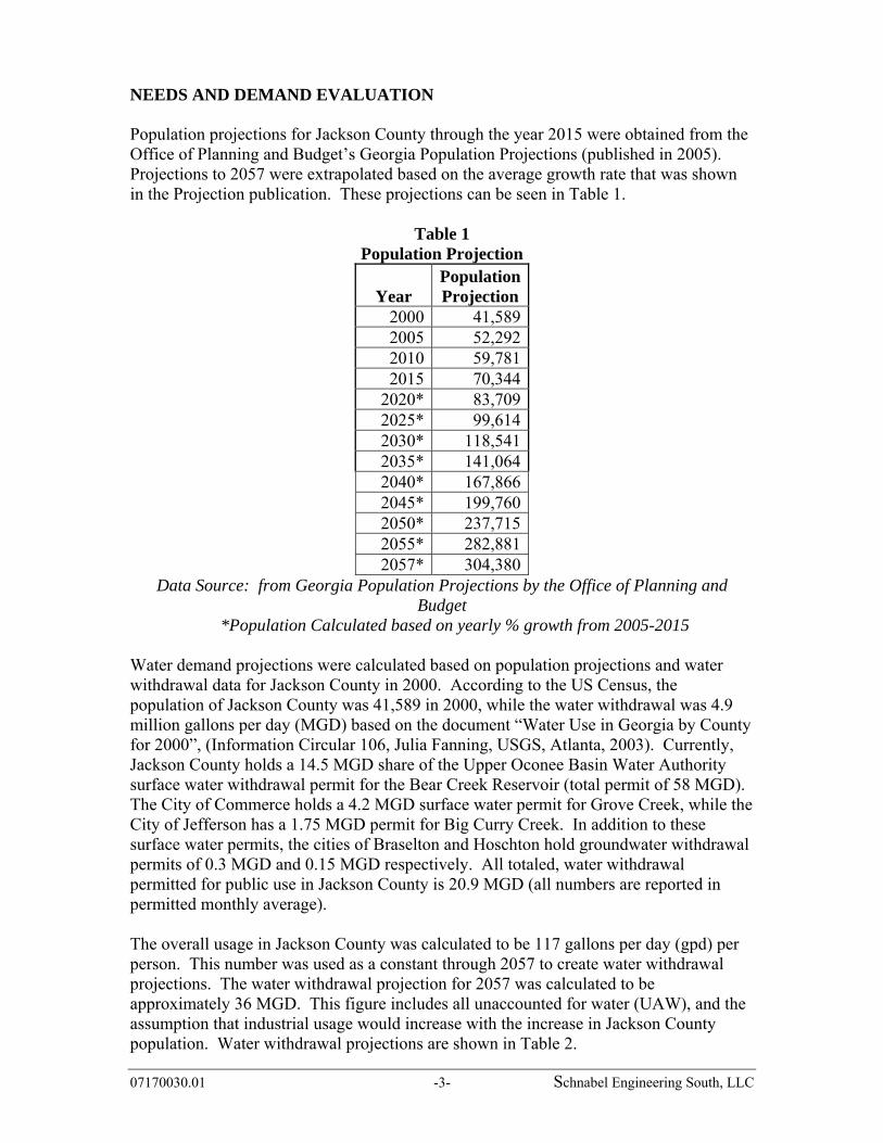
NEEDS AND DEMAND EVALUATION Population projections for Jackson County through the year 2015 were obtained from the Office of Planning and Budget’s Georgia Population Projections (published in 2005). Projections to 2057 were extrapolated based on the average growth rate that was shown in the Projection publication. These projections can be seen in Table 1.
Table 1 Population Projection
Year Population Projection
2000 41,5892005 52,2922010 59,7812015 70,344
2020* 83,7092025* 99,6142030* 118,5412035* 141,0642040* 167,8662045* 199,7602050* 237,7152055* 282,8812057* 304,380
Data Source: from Georgia Population Projections by the Office of Planning and Budget
*Population Calculated based on yearly % growth from 2005-2015 Water demand projections were calculated based on population projections and water withdrawal data for Jackson County in 2000. According to the US Census, the population of Jackson County was 41,589 in 2000, while the water withdrawal was 4.9 million gallons per day (MGD) based on the document “Water Use in Georgia by County for 2000”, (Information Circular 106, Julia Fanning, USGS, Atlanta, 2003). Currently, Jackson County holds a 14.5 MGD share of the Upper Oconee Basin Water Authority surface water withdrawal permit for the Bear Creek Reservoir (total permit of 58 MGD). The City of Commerce holds a 4.2 MGD surface water permit for Grove Creek, while the City of Jefferson has a 1.75 MGD permit for Big Curry Creek. In addition to these surface water permits, the cities of Braselton and Hoschton hold groundwater withdrawal permits of 0.3 MGD and 0.15 MGD respectively. All totaled, water withdrawal permitted for public use in Jackson County is 20.9 MGD (all numbers are reported in permitted monthly average). The overall usage in Jackson County was calculated to be 117 gallons per day (gpd) per person. This number was used as a constant through 2057 to create water withdrawal projections. The water withdrawal projection for 2057 was calculated to be approximately 36 MGD. This figure includes all unaccounted for water (UAW), and the assumption that industrial usage would increase with the increase in Jackson County population. Water withdrawal projections are shown in Table 2.

07170030.01 -4- Schnabel Engineering South, LLC
Table 2
Water Withdrawal Projection
Year
Water Withdrawal Projection
(MGD) 2000 4.92005 6.12010 7.02015 8.22020 9.82025 122030 142035 172040 202045 232050 282055 332057 36
Proximity to Surface Water Intakes Based on the GIS database developed for this project, the closest surface water intake structure is approximately 30.3 miles downstream of the dam on the Middle Oconee River. This structure is operated by the City of Athens – Clarke County. The downstream path is approximately 1.6 miles along Mountain Creek, 2.6 miles along Walnut Creek, and the remaining 26.1 miles along the Middle Oconee River. There is an intake structure approximately 7.6 miles to the east-southeast operated by the City of Jefferson on Curry Creek. The following figure illustrates the location of the nearest surface water intake locations to Middle Oconee – Walnut Creek 06.

07170030.01 -5- Schnabel Engineering South, LLC
Figure 2 Distance to Nearest Intake

07170030.01 -6- Schnabel Engineering South, LLC
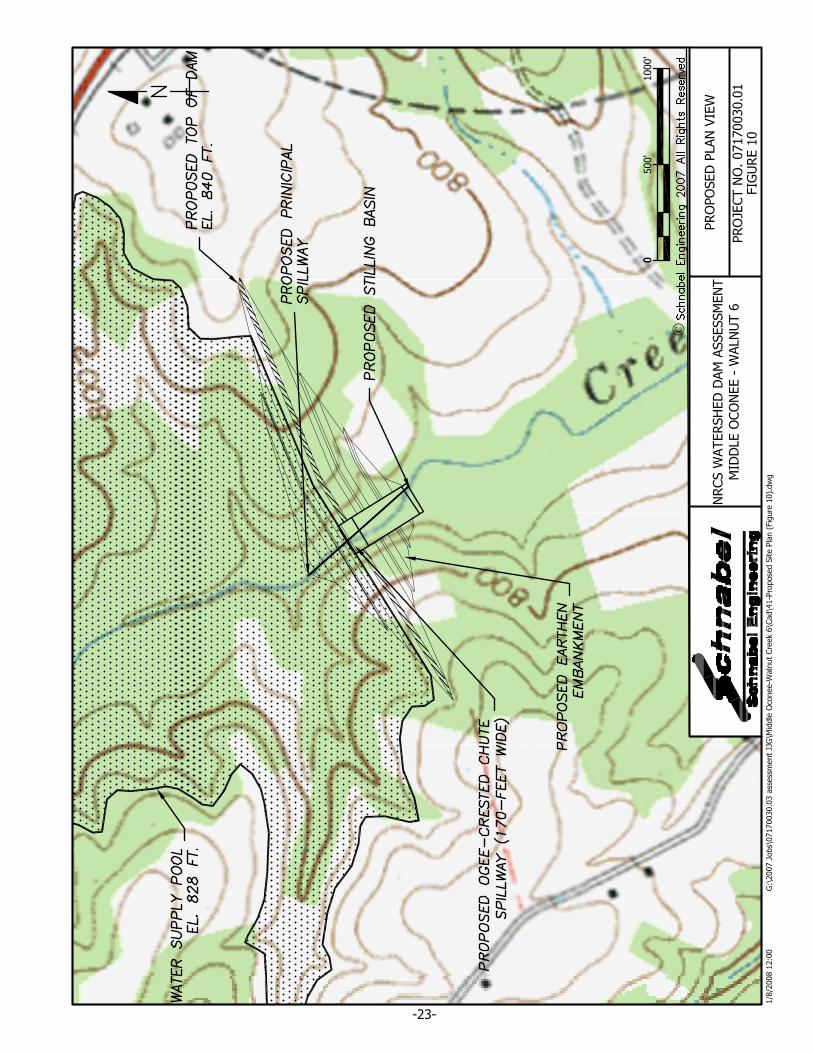
ENGINEERING FACTORS Proposed Dam The proposed dam, which will incorporate the existing dam, has a crest elevation of 840 feet, an auxiliary spillway elevation of 830 feet, and a normal pool elevation of 828 feet. The proposed dam will impound a reservoir that has a surface area of approximately 299 acres and storage volume of approximately 2,643 million gallons (MG). A plan view of the proposed reservoir is shown in Figure 3. Several engineering assumptions were made pertaining to spillway configuration. The spillway system for the proposed dam was assumed to consist of a principal spillway in the form of a 2’-6” by 7’-6” interior dimension reinforced concrete riser with a 30-inch diameter reinforced concrete low-level outlet pipe and an auxiliary spillway in the form of a 170-foot wide reinforced concrete chute spillway with ogee crest. The intent of the proposed principal spillway is to approximate the flows that are being discharged by the current spillway system during the two through 100-year storm events. The size of the auxiliary spillway was approximated by estimating the peak inflow that would occur during the Probable Maximum Precipitation (PMP) event and computing the spillway width that would be required to pass the estimated inflow with a given amount of hydraulic head. The available hydraulic head was determined by comparing the drainage basin area to lake surface area. The structures that had a drainage basin area to lake surface area ratio equal to or in excess of ten were allotted 15 feet of hydraulic head to pass the PMP inflows, while the structures that had a ratio of less than ten where allotted ten feet of hydraulic head to pass the PMP inflows. The assumption that the dam would be required to pass the inflow resulting from the PMP storm event is based on the history of the Georgia Department of Natural Resources Environmental Protection Division Safe Dams Program (Safe Dams) reviewing plans for water supply reservoir dams regardless of classification. As such, the dam would generally be required to comply with the engineering guidelines established by Safe Dams. Based upon the height of the dam (approximately 80 feet), the dam would be required to store and/or pass the inflows from the full PMP event safely. Additionally, the proposed dam would have a relatively high likelihood of being classified as high-hazard or Class ‘C’ by the NRCS, as well as Safe Dams. The proposed dam and flood pool will:
• Impact 4 structures • Require the purchase of 377 acres from 48 parcels • Require the purchase of 60 acres of easement area for state required buffer • Impact two local/county roads
Figure 4 displays the proposed reservoir area as well as the buffer and affected parcels. The 4 affected structures were identified from aerial photographs. The types of structures were not identified on the ground and could be houses, barns, trailers, etc. A more detailed ground survey will be required to determine the type of each structure and the corresponding purchase price of each structure.

07170030.01 -7- Schnabel Engineering South, LLC
Figure 3 Proposed Reservoir Area Map

07170030.01 -8- Schnabel Engineering South, LLC
Figure 4 Land Acquisition and Buffer Areas

07170030.01 -9- Schnabel Engineering South, LLC
SAFE YIELD ANALYSIS Definition Reservoir safe yield is generally defined as the reliable withdrawal rate of water with acceptable quality that can be provided by reservoir storage through the critical drought period. The critical drought period in the State of Georgia is defined as the drought of record and in any given drainage basin can vary depending on reservoir size and other factors. This study was based on the critical drought period from 1999-2002; however, the current drought could possibly exceed the existing drought of record. If this were to occur, the computed yields detailed herein would be reduced. Safe yield in this study was simulated using a constant average annual demand. The justification for this is that while total water demands after declaration of a drought condition are usually less than normal, this situation is typically offset by higher than average demands prior to declaration of the drought condition. Safe yield is dependent upon the storage and hydrologic (rainfall/runoff/evaporation) characteristics of the source and source facilities, the selected critical drought, upstream and downstream permitted withdrawals, and the minimum in-stream flow requirements. The proposed reservoir is a “pumped-storage” reservoir, where natural inflow into the reservoir is supplemented with pumped diversions from a nearby larger stream or river. Water is pumped from a larger river when runoff is plentiful, and is stored in the reservoir for times of drought. Pumped diversions increase safe yield, and generally result in fewer environmental impacts compared with reservoirs on main-stem rivers. Analysis Method The Allen Creek at Talmo (USGS 02217000) and the Middle Oconee River near Arcade (USGS 02217475) was selected for use in this analysis. The flows were then used to simulate streamflows in the Mountain Creek and Middle Oconee River basins. The modeled periods for the Allen Creek and Middle Oconee River gages extend from July 1951 to September 1971 and March 1987 to present, respectively, and includes two major droughts (1986-89, 1999-2002), plus the current drought. The diversion pump station was assumed to be located just upstream of the confluence of Mountain Creek with the Middle Oconee River. The straight line pipe distance between the dam and diversion location was estimated at 1.7 miles. The following drainage areas were used in the analysis:
• Dam Site (Mountain Creek): 2.53 mi2 • Diversion (Middle Oconee River): 49 mi2
The pumped diversion location and watershed is shown in Figure 5. The maximum estimated pool level at top of dam was selected during the initial screening phase based on USGS topographic mapping. From that level, a freeboard allowance of 10 feet between the top of dam and the auxiliary spillway was incorporated to pass the spillway design flood (assumed to be the probable maximum flood).

07170030.01 -10- Schnabel Engineering South, LLC
Figure 5 Watershed Location Map

07170030.01 -11- Schnabel Engineering South, LLC
Additional depth to maintain existing flood storage volume (542 Ac-ft, or 177 MG) was subtracted from the auxiliary spillway elevation to compute the water supply pool elevation used in the analysis of safe yield. Note that more detailed topographic mapping would be needed to more closely approximate the safe yield of the proposed reservoir. Table 3 summarizes the various reservoir elevations and approximate storage volumes. Calculation of stage-area and stage-storage curves is presented as Figure A-1 in the Appendix. Figure 6 below is the stage-storage curve for the reservoir.
Table 3 Summary of Reservoir Data
Stage Elevation Volume
(Million Gallons) Maximum Pool (Top of Dam) 840 3,800 Flood Pool (Auxiliary Spillway Crest) 830 2,800 Water Supply Pool 828 2,600
Figure 6
Stage-Storage Curve
A reservoir operations model was developed to incorporate daily gage data from the selected USGS gage and reservoir shape parameters for estimation of evaporation. The following assumptions were incorporated into the analysis for the estimation of safe yield: Assumptions:
1. Dead storage of 20% of gross reservoir storage was incorporated to allow for sediment storage and poor water quality in lower reservoir strata.
2. Usable water supply storage was assumed to be the water supply pool storage (calculated as noted above) less dead storage.
3. Pump station diversions were assumed to be from Middle Oconee River at the
760
780
800
820
840
0 500 1000 1500 2000 2500 3000 3500 4000
Volume (MG)
ELEV
ATI
ON
Water Supply Pool EL 828

07170030.01 -12- Schnabel Engineering South, LLC
location previously described. Diversions were assumed to occur whenever the reservoir level fell below full water supply pool. Pumped diversions were assumed to be bounded by pumping capacity and by flow restrictions on Middle Oconee River (noted below).
4. A minimum in-stream flow (MIF) of 30% AAF at the diversion pump station (Middle Oconee River) was used.
5. Allowance for downstream withdrawals reduced available flow in the stream. In addition to the MIF, the model provided for a prorated let-by with the following characteristics: Permittee: Upper Oconee Basin
Water Authority Athens-Clarke Co.
Public Utilities Downstream Withdrawal: 60 mgd 16 mgd Drainage Area: 351 mi2 388 mi2 Prorated Let-by: 8.38 mgd 2.02 mgd
. 6. No upstream withdrawals were identified. 7. For the dam site, minimum in-stream flow of 30/60/40 percent average annual
flow (AAF) was used. This MIF applies as follows: 30% AAF for July through November; 60% AAF for January through April; and 40% AAF for May, June and December.
8. Return flow from wastewater discharges or septic systems was not considered in the analysis.
9. Evaporation loss was based upon net historical evaporation rates (one standard deviation above average monthly values) as recorded at the University of Georgia in Athens. Lake evaporation was assumed to be equal to 70% of pan evaporation during each month. Surface area was approximated by a regression equation relating storage to surface area (Figure A-2, Appendix).
10. Streamflow data from the USGS gage was applied in direct proportion of drainage areas to simulate flow into the reservoir and at the diversion location.
11. Total seepage losses would be less than the MIF requirements and, therefore, did not need to be separately considered.
12. Safe yield is that quantity of water that can be provided to meet water demands during the critical drought period.
The attainable safe yield during the analyzed period was found by iteration of the daily mass balance equation:
The trial safe yield value was varied until the reservoir level just reached the dead storage value, and recovery of the reservoir was computed.
Ending Storage = (Beginning Storage) + (Natural Inflow) + (Pumped Inflow) – (Water Supply) – (Evaporation) – (MIF)

07170030.01 -13- Schnabel Engineering South, LLC
RESULTS Incorporating the above assumptions, the estimated safe yield of the site was computed. The results of the safe yield analysis are presented in Table 4 and Figure 7. It should be noted that these estimated safe yield values are based on USGS topographic mapping. The estimates could vary significantly based on more detailed mapping, which would be required as part of a final safe yield analysis. The table below presents the estimated safe yield and refill time for a range of pump capacities. We have assumed a refill time of 4 to 5 years is the maximum refill duration for selection of pump capacity (PC).
Table 4 Safe Yield Summary
Pump
Capacity (MGD)
Estimated Safe Yield (mgd)
Refill Time* (years)
5 2.2 7 10 3 4 15 3.5 4 20 4 4 30 4.2 4
*Refill time is the time from start of drawdown until complete refill to water supply pool
Figure 7 Estimated Safe Yield vs Pump Capacity
As presented in Figure 7, there is diminishing return (safe yield) with increasing pump capacity (reflecting pump station and pipeline cost). For the purposes of this analysis, an estimated economical safe yield & pump capacity combination were selected from the above graph. The estimated safe yield for this project is approximately 3 mgd for a pump capacity of 10 mgd.
0
0.5
1
1.5
2
2.5
3
3.5
4
4.5
0 5 10 15 20 25 30
Pump Capacity (mgd)
Safe
Yie
ld (m
gd)
Safe Yield = 3 mgd forPC = 10 mgd

07170030.01 -14- Schnabel Engineering South, LLC
These values were used to size and cost out the diversion facilities detailed later in this report. The variation of reservoir elevation over time for the above assumed safe yield and pump capacity is reflected in Figure 8.
Figure 8 Reservoir Elevation vs. Time
Elevation Vs. Time
760
770
780
790
800
810
820
830
Jul-51 Jul-59 Jul-67 Jul-75 Jul-83 Jul-91 Jul-99 Jul-07
Elev
atio
n (fe
et)
Water Supply PoolEL 828
Drought of Record
Dead Storage EL 794
Reservoir Bottom EL 762
Dam Site: Middle Oconee-Walnut Creek 06, DA = 2.53 sq.mi.Dam MIF: 30/60/40Diversion: Middle Oconee River, DA = 49 sq.mi.Diversion MIF: 30% AAFAllowance of U/S & D/S WithdrawalsWater Supply Pool Gross Storage: 2,600 MGDead Storage = 20% Gross StorageSafe Yield = 3 mgd
07170030.01 -15- Schnabel Engineering South, LLC
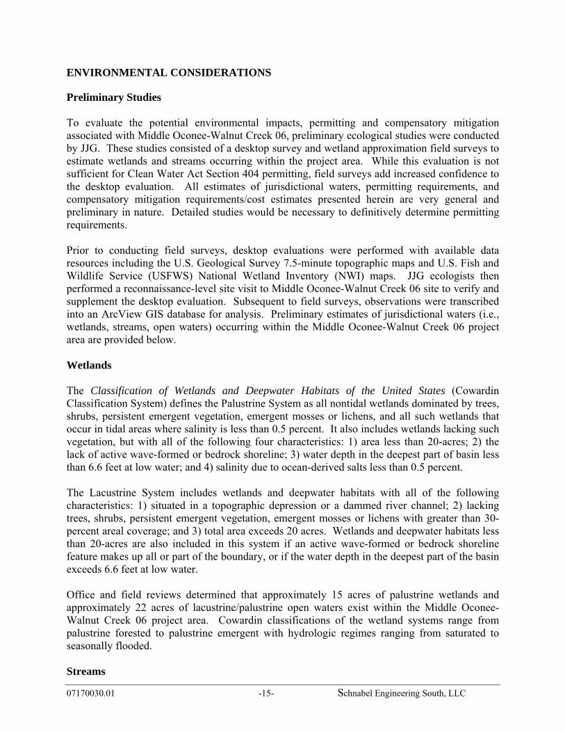
ENVIRONMENTAL CONSIDERATIONS Preliminary Studies To evaluate the potential environmental impacts, permitting and compensatory mitigation associated with Middle Oconee-Walnut Creek 06, preliminary ecological studies were conducted by JJG. These studies consisted of a desktop survey and wetland approximation field surveys to estimate wetlands and streams occurring within the project area. While this evaluation is not sufficient for Clean Water Act Section 404 permitting, field surveys add increased confidence to the desktop evaluation. All estimates of jurisdictional waters, permitting requirements, and compensatory mitigation requirements/cost estimates presented herein are very general and preliminary in nature. Detailed studies would be necessary to definitively determine permitting requirements. Prior to conducting field surveys, desktop evaluations were performed with available data resources including the U.S. Geological Survey 7.5-minute topographic maps and U.S. Fish and Wildlife Service (USFWS) National Wetland Inventory (NWI) maps. JJG ecologists then performed a reconnaissance-level site visit to Middle Oconee-Walnut Creek 06 site to verify and supplement the desktop evaluation. Subsequent to field surveys, observations were transcribed into an ArcView GIS database for analysis. Preliminary estimates of jurisdictional waters (i.e., wetlands, streams, open waters) occurring within the Middle Oconee-Walnut Creek 06 project area are provided below. Wetlands The Classification of Wetlands and Deepwater Habitats of the United States (Cowardin Classification System) defines the Palustrine System as all nontidal wetlands dominated by trees, shrubs, persistent emergent vegetation, emergent mosses or lichens, and all such wetlands that occur in tidal areas where salinity is less than 0.5 percent. It also includes wetlands lacking such vegetation, but with all of the following four characteristics: 1) area less than 20-acres; 2) the lack of active wave-formed or bedrock shoreline; 3) water depth in the deepest part of basin less than 6.6 feet at low water; and 4) salinity due to ocean-derived salts less than 0.5 percent. The Lacustrine System includes wetlands and deepwater habitats with all of the following characteristics: 1) situated in a topographic depression or a dammed river channel; 2) lacking trees, shrubs, persistent emergent vegetation, emergent mosses or lichens with greater than 30-percent areal coverage; and 3) total area exceeds 20 acres. Wetlands and deepwater habitats less than 20-acres are also included in this system if an active wave-formed or bedrock shoreline feature makes up all or part of the boundary, or if the water depth in the deepest part of the basin exceeds 6.6 feet at low water. Office and field reviews determined that approximately 15 acres of palustrine wetlands and approximately 22 acres of lacustrine/palustrine open waters exist within the Middle Oconee-Walnut Creek 06 project area. Cowardin classifications of the wetland systems range from palustrine forested to palustrine emergent with hydrologic regimes ranging from saturated to seasonally flooded. Streams
07170030.01 -16- Schnabel Engineering South, LLC
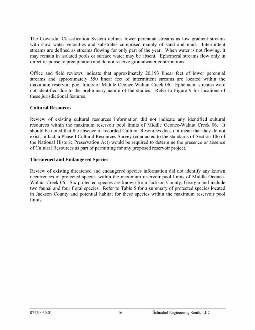
The Cowardin Classification System defines lower perennial streams as low gradient streams with slow water velocities and substrates comprised mainly of sand and mud. Intermittent streams are defined as streams flowing for only part of the year. When water is not flowing, it may remain in isolated pools or surface water may be absent. Ephemeral streams flow only in direct response to precipitation and do not receive groundwater contributions. Office and field reviews indicate that approximately 20,193 linear feet of lower perennial streams and approximately 550 linear feet of intermittent streams are located within the maximum reservoir pool limits of Middle Oconee-Walnut Creek 06. Ephemeral streams were not identified due to the preliminary nature of the studies. Refer to Figure 9 for locations of these jurisdictional features. Cultural Resources Review of existing cultural resources information did not indicate any identified cultural resources within the maximum reservoir pool limits of Middle Oconee-Walnut Creek 06. It should be noted that the absence of recorded Cultural Resources does not mean that they do not exist; in fact, a Phase I Cultural Resources Survey (conducted to the standards of Section 106 of the National Historic Preservation Act) would be required to determine the presence or absence of Cultural Resources as part of permitting for any proposed reservoir project. Threatened and Endangered Species Review of existing threatened and endangered species information did not identify any known occurrences of protected species within the maximum reservoir pool limits of Middle Oconee-Walnut Creek 06. Six protected species are known from Jackson County, Georgia and include two faunal and four floral species. Refer to Table 5 for a summary of protected species located in Jackson County and potential habitat for these species within the maximum reservoir pool limits.

07170030.01 -17- Schnabel Engineering South, LLC
Figure 9 Jurisdictional Areas Location Map

07170030.01 -18- Schnabel Engineering South, LLC
Table 5 Summary of Protected Species for Jackson County, Georgia
Scientific Name
Vernacular
Name
Federal Status
State Status
Habitat Present (Yes/No)
Preferred Habitat
Faunal
Cyprinella xaenura
Altamaha shiner NA E Yes
medium sized streams in runs or pools over sand to gravel substrates
Haliaeetus leucocephalus bald eagle D T No forages along rivers,
estuaries, and impoundments Floral
Amphianthus pusillus pool sprite T T No
shallow pools (>1 feet deep) on granite outcrops, where water collects after a rain No
Isoetes melanospora
black-spored quillwort E E No
shallow pools (> 1 ft deep) on granite outcrops, where water collects after a rain.
Isoetes tegetiformans
mat-forming quillwort E E No
vernal pools on granite outcrops; shallow, flat-bottomed pools that form in depressions granite outcrops
Veratrum woodii
Ozark bunchflower NA R Yes mesic hardwood forests
over basic soils
D = recently delisted, E= endangered, R = rare, T= threatened, NA= not applicable
Trout Streams Review of available resources did not indicate any primary or secondary trout streams within the maximum reservoir pool limits of Middle Oconee-Walnut Creek 06. 303(d) and 305(b) Listed Streams Review of available resources did not indicate any 303(d) or 305(b) listed streams within the maximum reservoir pool limits of Middle Oconee-Walnut Creek 06.
07170030.01 -19- Schnabel Engineering South, LLC
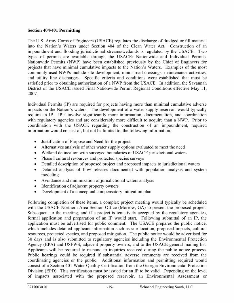
Section 404/401 Permitting The U.S. Army Corps of Engineers (USACE) regulates the discharge of dredged or fill material into the Nation’s Waters under Section 404 of the Clean Water Act. Construction of an impoundment and flooding jurisdictional streams/wetlands is regulated by the USACE. Two types of permits are available through the USACE: Nationwide and Individual Permits. Nationwide Permits (NWP) have been established previously by the Chief of Engineers for projects that have minimal cumulative impacts to the Nation’s Waters. Examples of the most commonly used NWPs include site development, minor road crossings, maintenance activities, and utility line discharges. Specific criteria and conditions were established that must be satisfied prior to obtaining authorization of a NWP from the USACE. In addition, the Savannah District of the USACE issued Final Nationwide Permit Regional Conditions effective May 11, 2007. Individual Permits (IP) are required for projects having more than minimal cumulative adverse impacts on the Nation’s waters. The development of a water supply reservoir would typically require an IP. IP’s involve significantly more information, documentation, and coordination with regulatory agencies and are considerably more difficult to acquire than a NWP. Prior to coordination with the USACE regarding the construction of an impoundment, required information would consist of, but not be limited to, the following information:
• Justification of Purpose and Need for the project • Alternatives analysis of other water supply options evaluated to meet the need • Wetland delineation with surveyed boundaries of USACE jurisdictional waters • Phase I cultural resources and protected species surveys • Detailed description of proposed project and proposed impacts to jurisdictional waters • Detailed analysis of flow releases documented with population analysis and system
modeling • Avoidance and minimization of jurisdictional waters analysis • Identification of adjacent property owners • Development of a conceptual compensatory mitigation plan
Following completion of these items, a complex project meeting would typically be scheduled with the USACE Northern Area Section Office (Morrow, GA) to present the proposed project. Subsequent to the meeting, and if a project is tentatively accepted by the regulatory agencies, formal application and preparation of an IP would start. Following submittal of an IP, the application must be advertised for public comment. The USACE prepares the public notice, which includes detailed applicant information such as site location, proposed impacts, cultural resources, protected species, and proposed mitigation. The public notice would be advertised for 30 days and is also submitted to regulatory agencies including the Environmental Protection Agency (EPA) and USFWS, adjacent property owners, and to the USACE general mailing list. Applicants will be required to respond to inquiries received during the public notice process. Public hearings could be required if substantial adverse comments are received from the coordinating agencies or the public. Additional information and permitting required would consist of a Section 401 Water Quality Certification from the Georgia Environmental Protection Division (EPD). This certification must be issued for an IP to be valid. Depending on the level of impacts associated with the proposed reservoir, an Environmental Assessment or

07170030.01 -20- Schnabel Engineering South, LLC
Environmental Impact Statement could be required by the USACE as well. Based on previous project experience, the level of controversy and environmental issues raised during agency and public review, a typical new reservoir project may require permitting times of 5 years or more. Compensatory Mitigation To determine the amount mitigation potentially required for jurisdictional impacts within the Middle Oconee-Walnut Creek 06, the USACE’s Standard Operating Procedure (SOP) for Compensatory Mitigation (March 2004) was utilized. The SOP uses a series of factors such as location, type, existing condition, type of impact, etc. to generate a multiplying “factor.” That factor is then multiplied by the impact area (acreage or linear footage) to calculate the required mitigation credits. To determine an average factor for jurisdictional areas associated with the Middle Oconee-Walnut Creek 06, various conditions observed during the field surveys were utilized. However, it is imperative to note that this document only serves as a guideline if impacts do not exceed 5,000 linear feet of stream or ten acres of wetland impacts. Potential impacts for the Middle Oconee-Walnut Creek 06 would significantly exceed this threshold and actual compensatory mitigation requirements would likely be substantially different from SOP estimates. Currently, the USACE Savannah District Office is developing a new SOP for large-scale projects focused on reservoirs. It is anticipated that this SOP would be issued mid-2008. Utilizing the 2004 SOP and the approximated acreage and linear feet of jurisdictional waters located within the Middle Oconee project area, an estimate of compensatory mitigation credits can be determined. Multiplying factors used for this analysis include: 6.7 for wetland systems, 5.7 for open waters, 12.7 for lower perennial streams, and 7.6 for intermittent streams. This factor was then multiplied by the acreage/ linear footage to determine an estimated number of mitigation credits required. The number of credits was then multiplied by an average credit price to estimate the final estimated compensatory mitigation cost associated with the Middle Oconee-Walnut Creek 06. Refer to Table 6 in the following section entitled “Project Construction Cost Estimate Narrative” for estimated impacts to jurisdictional waters and an estimate of mitigation credits required and associated costs. Stream Buffer Variance The Georgia Erosion and Sedimentation Act of 1975 (GESA), as amended, requires that a 25-foot vegetated buffer be maintained along all state waters. Any land disturbing activities within the buffer would require obtaining a stream buffer variance from the EPD. The local issuing authority is responsible for determining if state waters are on-site and is responsible for determining if a stream buffer variance is required. The GESA has a number of activities that are considered for stream buffer variances, including public water system reservoirs. Based on current regulations, reservoir construction would likely qualify for a variance. Attendant features such as pipelines and roadways, would likely be exempt from GESA regulations if stream crossings are constructed nearly perpendicular.

07170030.01 -21- Schnabel Engineering South, LLC
EPD Water Withdrawal Permit Georgia EPD requires a permit for withdrawal of 100,000 gallons per day or more of either surface water or ground water. In addition to justification of need for water for up to 50 years in the future, water withdrawal permits typically require the preparation of water conservation, drought contingency, water supply/watershed protection, and reservoir management plans. A public hearing may be required as part of the withdrawal permitting process. EPD requires that its comments on the component plans be addressed before moving forward with issuing the water withdrawal permit. Based on previous permitting experience, a water withdrawal permit can be obtained within 5 to 7 months, depending on EPD’s review time and the extent of their comments. Source Water Protection Plan Amendments to the Federal Safe Drinking Water Act (SDWA) have brought about a new approach for ensuring clean and safe drinking water served by public water supplies in the United States. Management of a drinking water source now requires a Source Water Protection Plan. This plan basically defines watershed management strategies for ensuring that the water supply is not compromised by potential pollutant sources. Typically these sources are unmanaged development, but they can also include industrial sources that can potentially contaminate the water supply. The entity that operates this reservoir for water supply would be required to produce and implement the Plan. The Plan should also address any source water from outside the reservoir watershed that would be used to fill the reservoir, i.e., pumped/storage sources. The cost and schedule for producing a Source Water Assessment and the corresponding Source Water Protection Plan have not been included in any of the estimates presented in the report.

07170030.01 -22- Schnabel Engineering South, LLC
PROJECT CONSTRUCTION COST ESTIMATE NARRATIVE Dam and Reservoir The construction cost estimate for the proposed dam was based upon the general description provided in the background section of the report. Additionally, the following assumptions were made regarding the geometry of the dam.
• Upstream slope of 3H to 1V • Downstream slope of 3H to 1V • Upstream slope wave action protection in the form of riprap from 30 feet below the crest
of the dam to 5 feet below the crest of the dam. Riprap supported by a berm located 30 feet below top of dam.
• Downstream slope having nearly horizontal 12-foot wide berms at 30-foot vertical intervals to control surface water runoff and erosion
• Crest of dam having a width of 25-feet In addition to the above geometric considerations, the following internal drainage configurations were also considered in the estimation of construction costs.
• Chimney drain located at the downstream edge of the crest • Trench drain located at 1/3 the distance from the downstream toe to the crest
A plan view and cross section of the proposed dam is provided in Figures 10 and 11. Contained below are the items estimated to develop the construction cost estimate. We caution that the quantities and associated prices are based upon limited engineering evaluation and will likely change as the project proceeds into detailed evaluation and design. Mobilization and Demobilization Mobilization and demobilization is a lump sum item estimated at 6 percent of the unit rate sum of the construction items. Erosion and Sedimentation Control Erosion and sedimentation control is a lump sum item estimated at 2 percent of the sum of unit rate construction items. Control of Water Control of water is a lump sum item estimated at 3 percent of the sum of unit rate construction items. This item includes the control of both surface water and groundwater and will likely consist of stream diversion, cofferdam construction and maintenance, pumping, and well points, as well as any other means of controlling water during construction.


07170030.01 -25- Schnabel Engineering South, LLC
Clearing Clearing is a unit rate item measured in acres associated with the removal of trees and other vegetation from the reservoir. The estimated area of clearing was assumed to be equal to the surface area of the reservoir at the normal pool elevation. Clearing and Grubbing Clearing and grubbing is a unit rate item measured in acres associated with the removal of trees, other vegetation, and associated root mats in the areas to receive structural fill or concrete. The estimated area of clearing and grubbing was assumed to be equal to the footprint of the proposed dam plus an additional 50-foot perimeter around the proposed dam. Earth Fill Earth Fill is a unit rate item measured in cubic yards. The computed volume of earth fill represents the estimated quantity required to construct the dam as described herein. The estimated quantity was computed using an AutoCad Civil 3D computer model based on the proposed grading and existing topography. In addition to the proposed embankment earth fill, foundation excavation backfill was calculated (see Excavation, Common for details) and added to the embankment earth fill to determine the total quantity of earth fill. Drain Fill Drain Fill is a unit rate item measured in cubic yards. The computed volume of drain fill represents the estimated quantity of fine and coarse-grained drain material required to construct the internal drainage system as described herein. For the purposes of this study, no differentiation was made between fine and coarse drain fill. In addition, the quantity for the trench drain was assumed to be equal to half of the chimney drain quantity. The chimney drain was assumed to have a top elevation equal to the proposed normal pool elevation and a bottom elevation approximated at the limits of the foundation excavation. The chimney drain was assumed to have a width of three feet and run the length of the dam from one abutment, into the floodplain, and up the other abutment tying into residual soils. Excavation, Common Excavation, Common is a unit rate item measured in cubic yards associated with the removal of unsuitable material (soils) within and adjacent to the footprint of the proposed dam. The volume of common excavation was calculated by approximating the surface area of the floodplain within the limits of clearing and grubbing as well as the depth of excavation within the same area. The surface area of the floodplain was approximated using available topographic maps. The depth of excavation was estimated from the boring data included in the design plans for the existing dam.

07170030.01 -26- Schnabel Engineering South, LLC
Riprap Riprap is a unit rate item measured in tons. The computed weight of riprap represents the estimated quantity required to construct the wave-action berm as described herein. Riprap was assumed to be placed on the upstream slope of the dam. The section of riprap was assumed to extend 30 vertical feet, have a thickness of about 2-¾ feet, and traverse the length of the proposed dam. Permanent Turf Establishment Permanent Turf Establishment is a unit rate item measured in acres associated with the establishment of a permanent turf at the conclusion of construction activities for the proposed dam. The estimated area of permanent turf establishment was assumed to be equal to the estimated area of clearing and grubbing. Concrete, Class 4000 Concrete, Class 4000 is a unit rate item measured in cubic yards associated with the construction of the reinforced concrete auxiliary chute spillway. The volume of concrete was estimated by comparing the proposed auxiliary spillway drop in elevation and width to the drops in elevation and widths of constructed reinforced concrete chute spillways. A relationship was developed between the drop in elevation and width of the constructed spillways and the required quantity of concrete. This relationship was applied to the proposed dam to estimate the quantity of concrete. Principal Spillway Reinforced Concrete Pressure Pipe Reinforced Concrete Pressure Pipe (RCPP) is a unit rate item measured in feet. The computed length of RCPP represents the estimated quantity required to construct the principal spillway conduit described herein. The RCPP was assumed to be placed through the base of the proposed dam from the upstream toe to the downstream toe. The diameter of the pipe was assumed to be equal to the diameter of the pipe in the existing dam. Concrete, Class 3000 (mass) Concrete, Class 3000 is a unit rate item measured in cubic yards associated with the construction of the concrete cradle beneath the principal spillway pipe. The concrete cradle was assumed to be designed as a Soil Conservation Service Type A2 cradle and run the length of the principal spillway pipe minus ten feet. Reinforced Concrete Riser The Reinforced Concrete Riser is a lump sum item associated with the construction of the reinforced concrete principal spillway structure. The cost was estimated by comparing the proposed principal spillway riser height to the heights of constructed reinforced concrete riser structures. A relationship was developed between the height of the constructed spillways and the cost to construct them. This relationship was utilized to estimate the cost of the proposed riser structure.

07170030.01 -27- Schnabel Engineering South, LLC
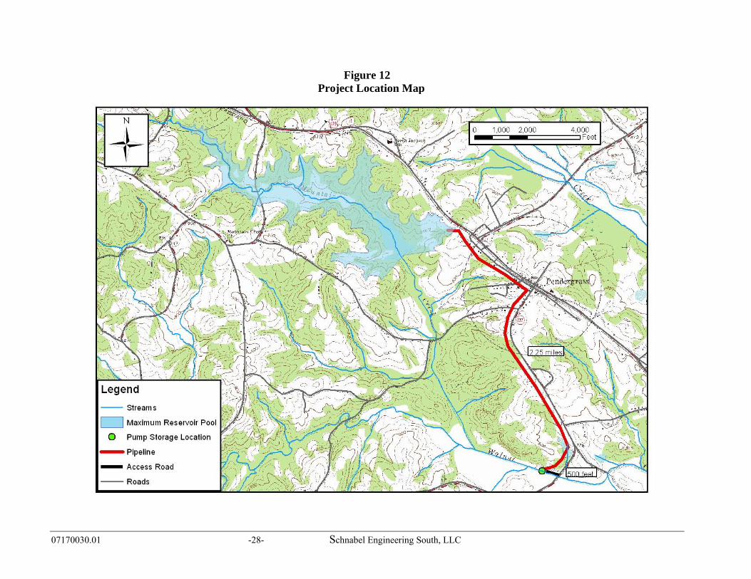
Land Acquisition The costs associated with land acquisitions are unit rate items based upon the number of acres that will need to be purchased at the top-of-dam elevation, the number of acres that will need to be managed for a 150-foot buffer around the normal pool, and the number of houses that will need to be purchased. For the purposes of the buffer management, only the portions of the buffer above top-of-dam elevation were considered. The costs to purchase the land were estimated based upon available records of recent land sales. The cost to manage the buffer was assumed to be 60 percent of the land purchase cost. The cost of each structure impacted was assumed to be $200,000. Roadway Relocation To construct the proposed project, two roads will be impacted. These roads may need to be raised, relocated, or modified to accommodate the new reservoir; however, no consideration was given to the relocation of roads in this study. A more detailed evaluation would need to be performed to evaluate the impact on existing roadways and the associated cost. Pump Station and Pipeline Cost Estimation The pump storage location for the Middle Oconee-Walnut Creek Reservoir 06 is located on Walnut Creek, just upstream of the State Route 332. The reservoir is located along Mountain Creek, approximately 1.5 miles upstream of its confluence with Walnut Creek. With a water supply pool elevation of 828 feet, Reservoir 06 has an average day yield of approximately 3 MGD. A 24-inch ductile iron pipe (DIP) was selected to carry water from the pump storage location to the reservoir. This pipeline is approximately 2.25 miles in length and will pump water from the storage location elevation of 730 feet, to the 828 feet height of the reservoir water surface. A cascading structure will need to be constructed where the pipe comes into the reservoir to provide aeration and erosion control. Three 5-MGD pumps were selected at the pump storage location to pump water to the reservoir. This gives a firm pumping capacity of 10-MGD, which is roughly twice the daily yield of the reservoir, the standard assumption for pump capacity. This pumping capacity will allow the reservoir to remain stable during times of peak water demand, as well as give redundancy in the case of failure in one of the pumps. An access road will need to be constructed in order to construct and maintain the pumping station on Walnut Creek. This road, shown on Figure 12, will run approximately 500 feet from State Route 332. The cost opinion for these components is found in the appendix.
07170030.01 -28- Schnabel Engineering South, LLC
Figure 12 Project Location Map

07170030.01 -29- Schnabel Engineering South, LLC
Compensatory Mitigation The simplest mitigation option is typically purchasing credits from a bank. Compensatory mitigation credits may be purchased from an approved mitigation bank or through the Georgia Land Trust Service Center if a bank is not available within the project area. Based on recent projects, wetland credits range from $7,000-$10,000 per credit and stream credits range from $70-$110 per credit. An option to purchasing credits is to obtain credits by conducting on-site restoration or preservation of jurisdictional waters.
Table 6 Middle Oconee-Walnut Creek 06 Estimated Impacts and Overall Mitigation
Banking Cost Analysis
Impact Type Estimated Impact
Acres/Linear Feet
Projected Credits Needed
Projected Cost* $90/stream credit
$7,500/wetland credit
Wetland 14.48 A. 97 $727,500 Intermittent Stream
550 l.f. 4,180 $376,200
Lower Perennial Stream
20,193 l.f. 256,451 $23,080,590
Open Water 21.71 A. 124 $930,000 Total 36.19 acres /
20,743 lf 221 wetland / 260,631 stream**
$25,114,290
*Cost is based on recent quotes from banks within the Upper Oconee River Basin. Actual banking price may be higher or lower than estimated depending on the date of purchase and credit availability.**Total required credits calculated using the March 2004 Standard Operating Procedure mitigating guidelines established by the US Army Corps of Engineers, which only serves as a guideline for large projects.
Estimated Project Construction Cost The total project cost is estimated at $79,000,000. Table A-5, located in the appendix, shows an itemized breakdown of the costs associated with enlarging the existing dam and reservoir. These costs are estimates and are based on multiple assumptions.

07170030.01 -30- Schnabel Engineering South, LLC
APPENDIX
FIGURES Figure A-1 Stage Storage / Stage Area Curves Figure A-2 Regression Equations for Area to Storage and Depth to Storage Figure A-3 Storage vs. Time and Elevation vs. Time for Assumed Safe Yield TABLES Table A-1 Summary of Opinion of Probable Construction Costs for Pumping Facilities and
Pipelines Table A-2 Opinion of Probable Construction Costs – River Intake and Pump Station Table A-3 Opinion of Probable Construction Costs – 30-inch Raw Water Line Table A-4 Opinion of Probable Construction Costs – Reservoir Inlet Structure Table A-5 Total Project Opinion of Cost

07170030.01 -31- Schnabel Engineering South, LLC
Figure A-1
Elev. Area Area Inc. Vol.Acres mg/in A-FT A-FT M Gal.
762 0.0 0 0 0 0767 20.0 1 50 50 16800 114.9 3 2239 2289 746820 228.2 6 3431 5720 1864840 377.4 10 6057 11777 3838
Middle Oconee-Walnut Creek 06
Cumulative Vol
Area and Storage Curves
Area - Elevation Curve
760
780
800
820
840
0 50 100 150 200 250 300 350 400
Area (Acres)
ELEV
ATI
ON
Water Supply Pool EL 828
Storage - Elevation Curve
760
780
800
820
840
0 500 1000 1500 2000 2500 3000 3500 4000
Volume (MG)
ELEV
ATI
ON
Water Supply Pool EL 828

07170030.01 -32- Schnabel Engineering South, LLC
Figure A-2Middle Oconee-Walnut Creek 06
Compute Regression Equation Relating Area to Storage (for Evaporation Calculations)
y = 0.0256x0.7272
R2 = 0.9996
0
2
4
6
8
10
12
0 500 1000 1500 2000 2500 3000 3500 4000
Storage (MG)
Are
a (m
g/in
)
Compute Regression Equation Relating Depth to Storage (for Elevation Estimates)
y = 2.1152x0.4384
R2 = 0.9989
0
10
20
30
40
50
60
70
80
90
0 500 1000 1500 2000 2500 3000 3500 4000
Storage (mg)
(Ele
v - E
lev
Min
)

07170030.01 -33- Schnabel Engineering South, LLC
Figure A-3Middle Oconee-Walnut Creek 06
Elevation Vs. Time
760
770
780
790
800
810
820
830
Jul-51 Jul-59 Jul-67 Jul-75 Jul-83 Jul-91 Jul-99 Jul-07
Ele
vatio
n (fe
et)
Water Supply Pool
Drought of Record
Dead Storage EL
Reservoir Bottom EL
Dam Site: Middle Oconee-Walnut Creek 06, DA = 2.53 sq.mi. Dam MIF: 30/60/40 Diversion: Middle Oconee River, DA = 49 sq.mi. Diversion MIF: 30% AAF Allowance of U/S & D/S Withdrawals Water Supply Pool Gross Storage: 2,600 MG Dead Storage = 20% Gross Storage Safe Yield = 3 mgd
Storage Vs. Time
0
500
1000
1500
2000
2500
3000
Jul-51 Jul-59 Jul-67 Jul-75 Jul-83 Jul-91 Jul-99 Jul-07
Sto
rage
(mg)
Water Supply Pool 2.6 BG
Drought of Record
Dead Pool Storage 530 MG
Dam Site: Middle Oconee-Walnut Creek 06, DA = 2.53 sq.mi. Dam MIF: 30/60/40 Diversion: Middle Oconee River, DA = 49 sq.mi. Diversion MIF: 30% AAF Allowance of U/S & D/S Withdrawals Water Supply Pool Gross Storage: 2,600 MG Dead Storage = 20% Gross Storage Safe Yield = 3 mgd

WATERSHED DAM ASSESSMENT - MIDDLE OCONEE-WALNUT CREEK 06
Jackson County, Georgia (7194-001)OPINION OF PROBABLE CONSTRUCTION COST ESTIMATE - CONCEPTUAL LEVEL
Summary by Division
Division
01 - W
ater I
ntake a
nd Pum
p Sta
tion a
nd
Access Road
02 - 24 -
inch R
aw W
ater F
orce M
ain a
nd
Venturi
Vault
03 - R
eservoir
Inle
t Stru
cture
TOTAL
% o
f Tota
l
1 $0.45 $0.14 $0.05 $0.63 8.80% MIDDLE OCONEE-WALNUT
2 $0.56 $0.00 $0.04 $0.61 8.42% CREEK 06:
3 $0.67 $0.01 $0.27 $0.96 13.32% Maximum Safe Reservoir Yield:
4 $0.06 $0.00 $0.00 $0.06 0.85% 3.0 MGD
5 $0.02 $0.00 $0.00 $0.02 0.31% RWPS Firm Pumping Capacity:
6 $0.00 $0.00 $0.00 $0.00 0.00% 10.0 MGD
7 $0.01 $0.00 $0.00 $0.01 0.17% RWFM Pipe Diameter: 24-inches
8 $0.03 $0.00 $0.00 $0.03 0.42%
9 $0.05 $0.00 $0.00 $0.05 0.69%
10 $0.00 $0.00 $0.00 $0.00 0.00%
11 $0.81 $0.00 $0.06 $0.87 12.08%
12 $0.00 $0.00 $0.00 $0.00 0.00%
13 $0.00 $0.00 $0.00 $0.00 0.00%
14 $0.07 $0.00 $0.00 $0.07 0.99%
15 $0.39 $1.33 $0.01 $1.73 23.98%
16 $0.52 $0.06 $0.00 $0.58 7.98%
17 $0.12 $0.02 $0.00 $0.14 1.94%
Structure Contingency $0.38 $0.00 $0.00 $0.38 5.23%
Markup $0.71 $0.26 $0.09 $1.07 14.82%
Structure Total (without
Contingency) $4.87 $1.81 $0.53 $7.21 100.00%
Project Contingency $1.46 $0.54 $0.16 $2.16 30.00%
Structure Total (with
Contingency) $6.33 $2.35 $0.68
All Figures are in Millions PROJECT TOTAL $9.37 M
12/19/2007C:\Documents and Settings\jabella\My Documents\Current Work\Watershed Dams Assessment REVISED\12 - Middle Oconee-Walnut Creek 06\00 - Middle Oconee-Walnut Creek 06 Conceptual Est Summary Dec
2007.xls

WATERSHED DAM ASSESSMENT - MIDDLE OCONEE-WALNUT CREEK 06
Jackson County, Georgia (7194-001)
OPINION OF PROBABLE CONSTRUCTION COST - CONCEPTUAL LEVEL
01 - Water Intake and PS
01
DECEMBER 2007
Spec. Labor $$ Material $$ Equipment $$ Subcontractor $$
No. Sect. Description Unit Qty Unit Total Unit Total Unit Total Unit Total Total
3 - Channel Intake Pump Station Pump Station Firm Capacity is 10MGD
Div 1
1 1000 General Conditions LS 1 $160,000 $126,600 $160,000 $0 $446,600
Div 2
2 2200 Earth Work LS 1 $13,600.00 $13,600 $8,400.00 $8,400 $3,479.00 $3,480 $252,800.00 $252,800 $278,280
3 Access Road LF 500 $0 $0 $0 $110.00 $55,000 $55,000
4 Creek Crossing EA 0 $0 $0 $0 $50,000.00 $0 $0
5 2831 10' Galv. Chain Link Fence LF 1000 $0 $0 $0 $30.00 $30,000 $30,000
6 2831 Dewatering / Pre-Excavation Preparation LS 1 $50,000.00 $50,000 $20,000.00 $20,000 $100,000.00 $100,000 $30,000.00 $30,000 $200,000
Div 3
7 3250 Water Stop LF 500 $1.25 $630 $2.00 $1,000 $0 $0 $1,630
8 3300 Concrete Bridge SF $2.00 $0 $0 $3.50 $0 $20.00 $0 $0
9 3300 Concrete LS 1 $212,885.00 $212,890 $394,527.00 $394,530 $65,650.00 $65,650 $0.00 $0 $673,070
Div 4
10 4210 Brick Veneer SF 2800 $0 $0 $0 $14.50 $40,600 $40,600
11 4220 Concrete Masonry Unit - Reinforced SF 2800 $0 $0 $0 $7.25 $20,300 $20,300
Div 5
10 5524 Aluminum Handrail LF 200 $6.00 $1,200 $35.00 $7,000 $2.90 $580 $0 $8,780
11 Ladder VF 20 $50.00 $1,000 $150.00 $3,000 $15.00 $300 $0 $4,300
12 5530 Aluminum Grating Landing SF 32 $10.00 $320 $45.00 $1,440 $10.00 $320 $0 $2,080
13 5530 Aluminum Grating SF 240 $10.00 $2,400 $20.00 $4,800 $0 $0 $7,200
Div 6
Div 7
14 Membrane Roofing SF 1225 $0 $0 $0 $5.00 $6,130 $6,130
15 Dampproofing - Walls SF 2800 $0 $0 $0 $0.56 $1,570 $1,570
16 1" Rigid Insulation - Walls SF 2800 $0 $0 $0 $1.07 $3,000 $3,000
17 7210 Walls - Core Fill Foam Insulation (12" CMU) SF 2800 $0 $0 $0 $0.61 $1,710 $1,710
Div 8
18 8120 Hollow Metal Doors, Hardware, and Frames - Single EA 10 $150.00 $1,500 $400.00 $4,000 $0 $0 $5,500
19 8120 Hollow Metal Doors, Hardware, and Frames - Double EA 2 $150.00 $300 $800.00 $1,600 $0 $0 $1,900
20 Windows LS 1 $3,000.00 $3,000 $8,000.00 $8,000 $1,000.00 $1,000 $0 $12,000
21 8331 Roll Up Aluminum Door (10'x12') EA 2 $800.00 $1,600 $4,500.00 $9,000 $50.00 $100 $0 $10,700
Div 9
22 9900 Painting LS 1 $0 $0 $0 $50,000.00 $50,000 $50,000
Div 10
Div 11
23 Screens EA 3 $3,500.00 $10,500 $200,000.00 $600,000 $500.00 $1,500 $0 $612,000
24 Eductors EA 15 $200.00 $3,000 $2,500.00 $37,500 $50.00 $750 $0 $41,250
25 Pumps (5 MGD, 105 Feet Static Head) EA 3 $4,500.00 $13,500 $48,000.00 $144,000 $1,000.00 $3,000 $0 $160,500
Div 12
Div 13
Div 14
26 Bridge Crane LS 1 $5,000.00 $5,000 $65,000.00 $65,000 $1,500.00 $1,500 $0 $71,500
Div 15
27 15062 Ductile Iron Pipe LS 1 $11,195.00 $11,200 $197,359.83 $197,360 $2,840.00 $2,840 $0.00 $0 $211,400
28 PVC Piping LS 1 $1,250.00 $1,250 $8,000.00 $8,000 $750.00 $750 $0 $10,000
29 Valves LS 1 $10,000.00 $10,000 $100,000.00 $100,000 $2,000.00 $2,000 $0.00 $0 $112,000
30 HVAC and Plumbing LS 1 $0 $0 $0 $60,000.00 $60,000 $60,000
Div 16
31 16000 Electrical LS 1 $0 $0 $0 $370,000.00 $370,000 $370,000
32 CCTV Allowance LS 0 $0 $0 $0 $0 $0
33 Ductbank LF 1000 $0 $0 $0 $150.00 $150,000 $150,000
Div 17
34 17000 Instrumentation LS 1 $0 $0 $0 $120,000.00 $120,000 $120,000
Contingency LS 10% $50,000 $174,000 $34,000 $119,000 $377,000
Subtotals $552,890 $1,915,230 $377,770 $1,310,110 $4,156,000
Assumptions:
Sales Tax @ 7.0% $134,100 Assumes that EPD will allow withdrawal from this source
Labor Burden @ 30.0% $165,900 15 foot wide Asphalt access road with 10-foot high fence
Bonds On Subs @ 1.5% $19,700 Pump Station firm capacity is 10MGD
Subtotal $4,475,700 Pump Station has a 3 channel intake
Fee @ 7.0% $313,300 Pump Station footprint is approximately 100 feet by 40 feet
Insurance & Bonds @ 1.7% $81,400 Pump Station main building footprint is approximately 35 feet by 35 feet
Pump Station main building also houses the electrical room and is made of brick and block
Estimated Construction Cost $4,870,400 A Transformer is being provided by the Utility Company at the access road entrance
Estimate DOES NOT include easements acquisitions, land acquisitions, withdrawal permits
or mitigations required to build the pump station
01 - Middle Oconee-Walnut Creek 06 Intake and Pump Station
12/19/2007 Page 1C:\Documents and Settings\jabella\My Documents\Current Work\Watershed Dams Assessment REVISED\12 - Middle Oconee-Walnut Creek 06\01 - Middle Oconee-Walnut Creek 06 Intake and Pump Station .xls

WATERSHED DAM ASSESSMENT - (7194-001)
MIDDLE OCONEE-WALNUT CREEK 06
OPINION OF PROBABLE CONSTRUCTION COST ESTIMATE - CONCEPTUAL LEVEL
02 - 24-inch Raw Water Line
02
DECEMBER 2007
Spec. Labor $$ Material $$ Equipment $$ Subcontractor $$
No. Sect. Description Unit Qty Unit Total Unit Total Unit Total Unit Total Total
Div 1
1 1000 General Conditions LS 1 $50,000 $36,300 $50,200 $0 $136,500
Div 2
2 2125 Erosion and Sedimentation Control Maintenance - with Unit Bid MTH $0 $0 $0 $0 $0
3 Dewatering LS $0 $0 $0 $0 $0
4 2510 Asphalt Concrete Pavement - with Unit Bid LS $0 $0 $0 $0 $0
5 2523 Concrete Sidewalk and Curbs - with Unit Bid LS $0 $0 $0 $0 $0
Div 3
6 3300 Miscellaneous Concrete (Venturi Vault) LS 1 $1,200.00 $1,200 $12,500.00 $12,500 $1,000.00 $1,000 $0.00 $0 $14,700
Div 4
Div 5
Div 6
Div 7
Div 8
Div 9
Div 10
Div 11
Div 12
Div 13
Div 14
Div 15
7 24" DIP Depth 6 Depth of Cover 4
8 24" Pipe Excavation - Earth (compacted volume) CY 9917 $0.75 $7,438 $0 $3.00 $29,750 $0 $37,188
9 24" Pipe Excavation - Trench Rock (compacted volume) CY 3306 $0 $0 $0 $35.00 $115,694 $115,694
10 Trench Box LF 11900 $0 $1.00 $11,900 $0 $0 $11,900
11 24" DIP Pressure Class 250 LF 10400 $6.00 $62,400 $58.99 $613,517 $2.50 $26,000 $0 $701,917
12 24" Pipe Bedding (compacted volume) CY 2204 $1.00 $2,204 $13.00 $28,648 $1.00 $2,204 $0 $33,056
13 24" Pipe Backfill (compacted volume) CY 9634 $1.00 $9,634 $0 $4.00 $38,536 $0 $48,169
14 Import Backfill Materials (loose volume, assume 10% swell) CY 311 $0 $13.00 $4,044 $0 $0 $4,044
15 Haul off Rock (assume 15% swell) - with Unit Bid CY 3801 $0 $0 $0 $15.00 $57,021 $57,021
16 24" 90-degree Bend EA 1 $127.20 $127 $3,398.04 $3,398 $50.00 $50 $0 $3,575
17 24" 45-degree Bend EA 3 $127.20 $382 $1,737.81 $5,213 $50.00 $150 $0 $5,745
18 24" 22.5-degree Bend EA 6 $127.20 $763 $1,815.65 $10,894 $50.00 $300 $0 $11,957
19 24" 11.25-degree Bend EA 0 $127.20 $0 $2,746.39 $0 $50.00 $0 $0 $0
20 24" DIP Pressure Class 250 RJ LF 1500 $9.17 $13,749 $81.17 $121,752 $2.50 $3,750 $0 $139,251
21
22 Earthwork Calculations $0 $0 $0 $0 $0
23 Pipe Excavation - Total Compacted Volume CY 13222 $0 $0 $0 $0 $0
24 Rock - Total Compacted Volume (assume 25% of excavation) CY 3306 $0 $0 $0 $37.00 $122,306 $122,306
25 Pipe Bedding - Total Compacted Volume CY 2204 $0 $0 $0 $0 $0
26 Pipe Backfill - Total Compacted Volume Needed CY 9634 $0 $0 $0 $0 $0
27 On-Site Backfill Material Available - Compacted Volume CY 9917 $0 $0 $0 $0 $0
28 Materials for Disposal - Compacted Volume CY 283 $5.00 $1,414 $0 $5.00 $1,414 $0 $2,828
29
30 Air Release Valve and Manhole (3 each) LS 1 $2,200.00 $2,200 $26,400.00 $26,400 $1,800.00 $1,800 $0.00 $0 $30,400
31
Div 16
32 16000 Electrical LS 1 $0 $0 $0 $55,000.00 $55,000 $55,000
Div 17
33 17000 Venturi Meter LS 1 $1,000.00 $1,000 $10,500.00 $10,500 $500.00 $500 $0 $12,000
34 17000 Instrumentation LS 1 $0 $0 $0 $7,500.00 $7,500 $7,500
Contingency LS 0% $0 $0 $0 $0 $0
Subtotals $152,510 $885,066 $155,653 $357,521 $1,550,750
Assumptions:
Sales Tax @ 7.0% $62,000 Estimate DOES NOT include easements acquisitions, land acquisitions or mitigations required
Labor Burden @ 30.0% $45,800 to build the pump station
Bonds On Subs @ 1.5% $5,400 Assumed 25% of the excavated material is rock
Subtotal $1,663,950
Fee @ 7.0% $116,500
Insurance & Bonds @ 1.7% $30,300
Estimated Construction Cost $1,810,750 $152 per LF
02 - 24-inch Raw Water Line with Venturi Vault
12/19/2007 Page 1C:\Documents and Settings\jabella\My Documents\Current Work\Watershed Dams Assessment REVISED\12 - Middle Oconee-Walnut Creek 06\02 - Middle Oconee-Walnut Creek 06 24-inch RW Pipe.xls

WATERSHED DAM ASSESSMENT - (7194-001)
MIDDLE OCONEE-WALNUT CREEK 06
OPINION OF PROBABLE CONSTRUCTION COST - CONCEPTUAL LEVEL
03 - Reservoir Inlet Structure
03
DECEMBER 2007
Spec. Labor $$ Material $$ Equipment $$ Subcontractor $$
No. Sect. Description Unit Qty Unit Total Unit Total Unit Total Unit Total Total
Div 1
1 1000 General Conditions LS 1 $18,000 $14,500 $18,300 $0 $50,800
Div 2
2 2200 Earth Work LS 1 $5,000.00 $5,000 $2,639.00 $2,640 $4,926.00 $4,930 $31,300.00 $31,300 $43,870
Div 3
3 3250 Water Stop LF 500 $1.25 $630 $2.00 $1,000 $0 $0 $1,630
4 3300 Concrete LS 1 $82,952.00 $82,950 $159,839.00 $159,840 $26,200.00 $26,200 $0.00 $0 $268,990
Div 4
Div 5
7 5524 Aluminum Handrail LF $6.00 $0 $35.00 $0 $2.90 $0 $0 $0
8 Ladder VF $50.00 $0 $150.00 $0 $15.00 $0 $0 $0
9 5530 Aluminum Grating Landing SF $10.00 $0 $45.00 $0 $10.00 $0 $0 $0
10 5530 Aluminum Grating SF $10.00 $0 $20.00 $0 $0 $0 $0
Div 6
Div 7
Div 8
Div 9
10 9900 Painting LS $0 $0 $0 $0 $0
Div 10
Div 11
11 Sluice Gates and Operators EA 2 $2,500.00 $5,000 $25,000.00 $50,000 $1,000.00 $2,000 $0 $57,000
Div 12
Div 13
Div 14
Div 15
12 15062 Ductile Iron Pipe LS 1 $1,000.00 $1,000 $8,500.00 $8,500 $500.00 $500 $0 $10,000
Div 16
13 16000 Electrical LS $0 $0 $0 $70,000.00 $0 $0
Div 17
14 17000 Instrumentation LS $0 $0 $0 $25,000.00 $0 $0
Contingency LS 0% $0 $0 $0 $0 $0
Subtotals $112,580 $236,480 $51,930 $31,300 $432,290
Sales Tax @ 7.0% $16,600
Labor Burden @ 30.0% $33,800
Bonds On Subs @ 1.5% $500
Subtotal $483,190
Fee @ 7.0% $33,800
Insurance & Bonds @ 1.7% $8,800
Estimated Construction Cost $525,790
03 - Reservoir Inlet Structure
12/19/2007 Page 1C:\Documents and Settings\jabella\My Documents\Current Work\Watershed Dams Assessment REVISED\12 - Middle Oconee-Walnut Creek 06\03 - Reservoir Inlet Structure for Middle Oconee-Walnut Creek 06.xls

Item . Description of Work Estimated Unit Unit Price AmountNo. Quantity
1. Mobilization and 1 Job Lump Sum $813,286Demobilization
2. Erosion & Sediment Control 1 Job Lump Sum $271,095
3. Control of Water 1 Job Lump Sum $406,643
4. Clearing 299 Ac $2,500 $747,500
5. Clearing & Grubbing 22 Ac $5,000 $110,000
6. Earth Fill 680,524 Cu-Yd $4 $2,722,096
7. Drain Fill 14,973 Cu-Yd $75 $1,122,975
8. Excavation, Common 45,108 Cu-Yd $5 $225,540
9. Riprap 19,370 Ton $75 $1,452,750
10. Permanent Turf Establishment 22 Ac $2,000 $44,000
11. Concrete, Class 4000 (reinforced) 7,800 Cu-Yd $850 $6,630,000
12. Concrete, Class 3000 (mass) 131 Cu-Yd $400 $52,400
13. 30-Inch RCP 700 Feet $400 $280,000
14. Principal Spillway Riser 1 Lump Sum $167,500 $167,500
Dam Construction Cost Estimate $15,045,785
15. 24-Inch Pipeline 1 Lump Sum $1,810,000 $1,810,000
16. Cascading Structure 1 Lump Sum $530,000 $530,000
Table A-5
Middle Oconee-Walnut Creek No. 6
TOTAL PROJECT OPINION OF COST

17.Pumping Station (Including Raw Water Pumps and Access Road) 1 Lump Sum $4,870,000 $4,870,000
Pump Station and Pipeline Cost Estimate $7,210,000
18. Land Acquisition 377 Ac $20,000 $7,540,000
19. Easement Acquisition 60 Ac $12,000 $720,000
20. Building Acquisition 4 Buildings $200,000 $800,000
Land Acquisition Cost Estimate $9,060,000
21. Wetland 97 Credits $7,500 $727,500
22. Intermittent Stream 4,180 Credits $90 $376,200
23. Lower Perennial Stream 256,451 Credits $90 $23,080,590
24. Open Water 124 Credits $7,500 $930,000
Impacts and Overall Mitigation Cost Estimate $25,114,290
$56,430,075
$14,107,519
$8,464,511
$79,002,105
$79,000,000
*Professional services include but are not limited to engineering, construction managementlegal, appraisals, and environmental consulting.
Suggested Project Estimate
Contingency at 25%
Construction, Land Acquisition, Mitigation Estimate
Professional Services at 15% *
Total Project Estimate