water-stable cspbbr 3 perovskite quantum-dot luminous
TRANSCRIPT
Water-stable CsPbBr3 perovskite quantum-dotluminous fibers fabricated by centrifugal spinningfor dual white light illumination andcommunicationBINHAI YU,1 SHUNMING LIANG,1 FENGYI ZHANG,1 ZONGTAO LI,1,2 BIN LIU,3 AND XINRUI DING1,*1National and Local Joint Engineering Research Center of Semiconductor Display and Optical Communication Devices,South China University of Technology, Guangzhou 510641, China2Provincial Key Laboratory of Semiconductor Micro Display, Foshan Nationstar Optoelectronics Company Ltd., Foshan 528000, China3Guangdong Provincial Key Laboratory of Sensor Technology and Biomedical Instrument, School of Biomedical Engineering,Sun Yat-sen University, Guangzhou 510006, China*Corresponding author: [email protected]
Received 7 April 2021; revised 8 June 2021; accepted 20 June 2021; posted 22 June 2021 (Doc. ID 427066); published 29 July 2021
Lead halide perovskite quantum dots (PQDs) display remarkable photoelectric performance. However, defectssuch as weak stability in air and water environments limit the development of lead halide PQDs in solid-state lightapplications. Herein, centrifugal spinning is used for the fabrication of stable luminous CsPbBr3 PQD nano-fibers. After immersion in water for 11 months, the PQD fibers still maintained considerable photoluminescencequantum yield, showing high stability in hostile environments. The water-stability mechanism of the fibers can beexplained by the changing defect density, crystal growth of PQDs, and the molecular transformation at the fibersurface. The white LED based on the CsPbBr3 fibers exhibits satisfying color gamut performance (128% ofNational Television System Committee). Due to the short photoluminescence lifetime of CsPbBr3 PQDs,the communication potential is also considered. The CsPbBr3 fibers obtained by centrifugal spinning presenta bandwidth of 11.2 MHz, showing promising performance for solid-state light and visible light communicationapplications. © 2021 Chinese Laser Press
https://doi.org/10.1364/PRJ.427066
1. INTRODUCTION
Lead halide perovskites have unique advantages, including nar-row emission bandwidth, high quantum yield, and full emis-sion spectrum of visible light [1,2], and, due to their superiorluminescence and photoelectric conversion abilities, they havegained much attention in the photoelectric field in recent years.Novel devices such as solar cells [3], light-emitting diodes(LEDs) [4,5], lasers [6], and photodetectors (PDs) [7–11] havebeen manufactured utilizing these perovskites. Among multi-farious perovskites, CsPbX3 (X � Cl, Br, I) perovskites notonly show remarkable luminescence performance but alsoexhibit potential for popularization due to their large-scale fab-rication ability. Inorganic CsPbX3 perovskites have been widelystudied due to their continuously optimized synthesis methods.Protesescu’s group proposed an inexpensive and simple methodfor all-inorganic CsPbX3 perovskite quantum dots (PQDs)synthesis [1]. After that, Tong’s group used an ultrasonicmethod for CsPbX3 synthesis, which is more efficient thanother methods [12]. These CsPbX3 PQDs have a high photo-luminescence quantum yield, tunable spectra over the entire
visible light region of 410 to 700 nm, and a relatively shortphotoluminescence (PL) lifetime, showing great potential inillumination and communication applications [13–18].However, drawbacks of CsPbX3 PQDs, such as instability inwater and air [19], toxicity to the environment [20], and com-plex encapsulation processes [21], hinder their application insolid-state light (SSL) applications.
Traditional film encapsulation of quantum dots (QDs)causes a serious quenching effect, which will decrease the lu-minous efficiency of QD devices [22,23]. For SSL applications,the general strategy is to encapsulate the PQDs into other ma-terials that are hydrophobic, nondegradable, or mesoporous,such as silicon and polymers. Compounds fabricated by thestrategy mentioned above usually have enhanced stability inhostile environments. Li’s group used a superhydrophobic aero-gel inorganic matrix (S-AIM) with open structures to encapsu-late CsPbX3 PQDs to enhance water stability [21]. TheCsPbBr3 PQDs integrated with S-AIM exhibit a relatively highphotoluminescence quantum yield compared with nonpro-cessed PQDs. However, mesoporous materials will inevitably
Research Article Vol. 9, No. 8 / August 2021 / Photonics Research 1559
2327-9125/21/081559-10 Journal © 2021 Chinese Laser Press
lead to PQDs being partially exposed in ambient environments.To further improve their stability, secondary encapsulation isalso needed for PQDs. Wei’s group proposed an efficient strat-egy called “swelling–shrinking” [24]. PQDs were packaged inpolystyrene (PS) microbeads, forming PQD-PS microbeads.These beads not only retained high luminescence but also ex-hibited superior water-resistant properties. However, this strat-egy requires vacuum evaporation, temperature conditions, andtime-consuming processes. In addition to the methods men-tioned above, fiber spinning, especially electrospinning, isone of the most common methods used for PQD encapsulation[25–29]. The luminous fibers fabricated by electrospinninghave considerable enhancement in PQD stability. However,the electrospinning process is relatively inefficient and time-consuming. Microfluidic spinning is a novel method used tofabricate ordered fibers, but the devices used for fabricationare complex, and the process is also inefficient [30,31].
Centrifugal spinning is a pure mechanical spinning methodused for fiber fabrication. Centrifugal spinning has been used tofabricate nanoscale fibers, such as barium titanate nanofibers[32], SiO2 nanofibers [33], and polylactic acid nanofibers[34], for structure, filtration, biological, and many other appli-cations [35]. The nanofiber diameters resulting from electro-spinning and centrifugal spinning are approximately 50 nmto 2 μm and 25 nm to 3 μm, respectively [35]. The productionrate of electrospinning is approximately 10 μL/min, while therate of centrifugal spinning can reach 1 mL/min [32,36]. Theelectrospinning process often requires hours, while centrifugalspinning can be performed in a few seconds. Here, we fabri-cated CsPbBr3 polystyrene perovskite quantum dot (PQD-PS) luminous fibers by centrifugal spinning for the first time.The fabricated CsPbBr3 PQD-PS fibers show superior perfor-mance in water and air resistance while maintaining a relativelyhigh luminous efficiency, which makes them promising com-pounds for solid-state light applications. Furthermore, due tothe short fluorescence lifetime of perovskite, the visible lightcommunication (VLC) potential of the PQD-PS fibers is alsoconsidered [37]. The results show that the PQD-PS fiberspresent promising performance in both SSL and VLC appli-cations.
2. EXPERIMENT
A. ChemicalsAll chemicals used in this study were as follows: lead bromide(PbBr2, Macklin, AR, 99.0%), cesium carbonate (Cs2CO3,Macklin, AR, 99%), oleic acid (Macklin, AR), oleylamine(Macklin, C18: 80%–90%), and 1-octadecene [Macklin,>90% (GC)], toluene (Guangzhou Chemistry, AR, >99.5%),hexane (Richjoint, AR, >97%), polystyrene (PS, Sigma-Aldrich, 192000 MW), UV glue (Norland, NOA65), andCdSe/ZnS (Beijing Beida Jubang, 625 nm).
B. Synthesis of CsPbBr3 Perovskite Quantum DotsCsPbBr3 PQDs were synthesized by the facile ultrasonicmethod shown in Fig. 1. First, PbBr2 (0.11 g), Cs2CO3
(0.0326 g), 1-octadecene (10 mL), oleic acid (0.1 mL), andoleylamine (2 mL) were mixed in a reagent bottle. Then,the mixed solution was sonicated for 5 min (Shanghai Shengxi,
FS-300N). After that, the mixed solution was processed in an icebath (2 min). The solution was centrifuged twice after immersionin an ice bath. The first centrifugation step (10,000 r/min,10 min) involved removing redundant 1-octadecene, oleic acid,and oleylamine; the second centrifugation step (2500 r/min,5 min) involved depositing perovskite crystals with large grainsizes. The sediment of the second centrifugation step was dis-persed by toluene. In addition, the final PQDs were dispersedin toluene.
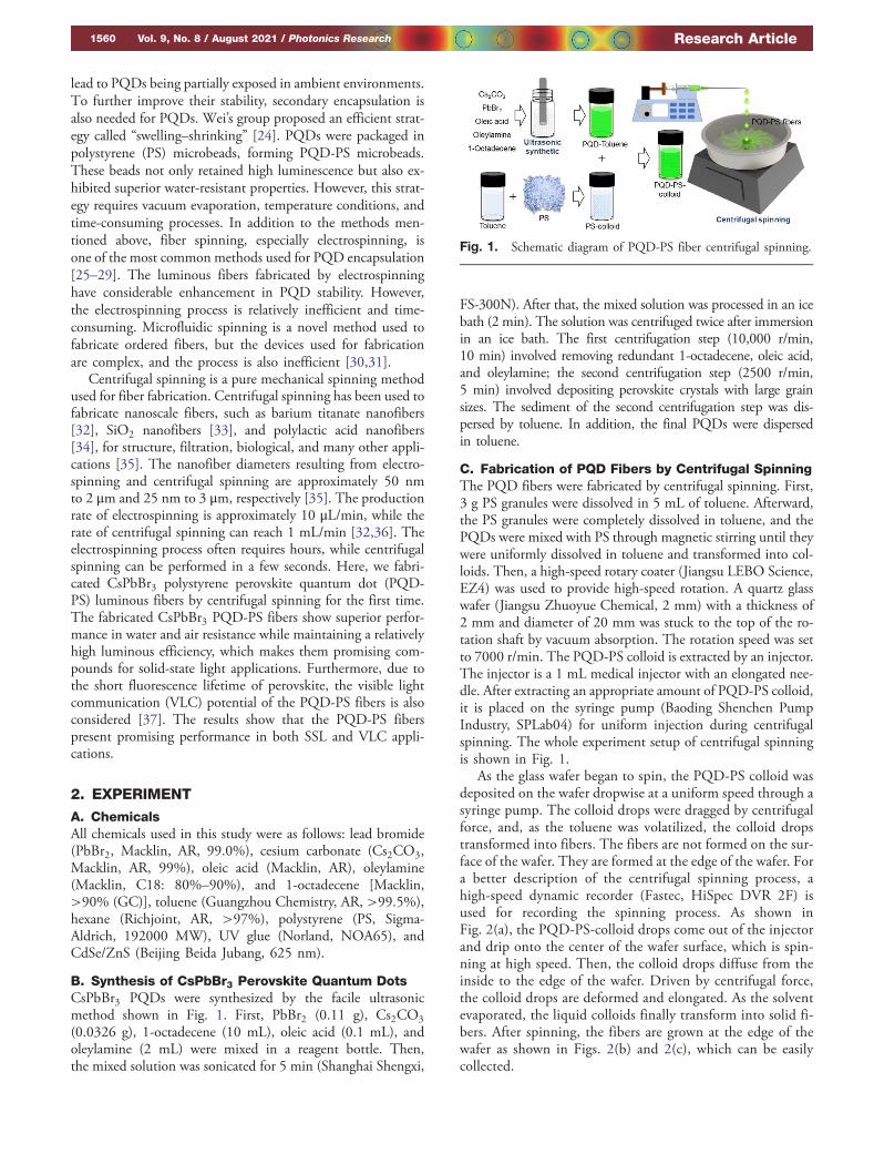
C. Fabrication of PQD Fibers by Centrifugal SpinningThe PQD fibers were fabricated by centrifugal spinning. First,3 g PS granules were dissolved in 5 mL of toluene. Afterward,the PS granules were completely dissolved in toluene, and thePQDs were mixed with PS through magnetic stirring until theywere uniformly dissolved in toluene and transformed into col-loids. Then, a high-speed rotary coater (Jiangsu LEBO Science,EZ4) was used to provide high-speed rotation. A quartz glasswafer (Jiangsu Zhuoyue Chemical, 2 mm) with a thickness of2 mm and diameter of 20 mm was stuck to the top of the ro-tation shaft by vacuum absorption. The rotation speed was setto 7000 r/min. The PQD-PS colloid is extracted by an injector.The injector is a 1 mL medical injector with an elongated nee-dle. After extracting an appropriate amount of PQD-PS colloid,it is placed on the syringe pump (Baoding Shenchen PumpIndustry, SPLab04) for uniform injection during centrifugalspinning. The whole experiment setup of centrifugal spinningis shown in Fig. 1.
As the glass wafer began to spin, the PQD-PS colloid wasdeposited on the wafer dropwise at a uniform speed through asyringe pump. The colloid drops were dragged by centrifugalforce, and, as the toluene was volatilized, the colloid dropstransformed into fibers. The fibers are not formed on the sur-face of the wafer. They are formed at the edge of the wafer. Fora better description of the centrifugal spinning process, ahigh-speed dynamic recorder (Fastec, HiSpec DVR 2F) isused for recording the spinning process. As shown inFig. 2(a), the PQD-PS-colloid drops come out of the injectorand drip onto the center of the wafer surface, which is spin-ning at high speed. Then, the colloid drops diffuse from theinside to the edge of the wafer. Driven by centrifugal force,the colloid drops are deformed and elongated. As the solventevaporated, the liquid colloids finally transform into solid fi-bers. After spinning, the fibers are grown at the edge of thewafer as shown in Figs. 2(b) and 2(c), which can be easilycollected.
Fig. 1. Schematic diagram of PQD-PS fiber centrifugal spinning.
1560 Vol. 9, No. 8 / August 2021 / Photonics Research Research Article
D. Measurement and CharacterizationThe crystal structure of the prepared PQDs was characterizedby transmission electron microscopy (JEM-2100F, JEOL) at200 kV. The morphology of the PQD-PS fibers was character-ized by scanning electron microscopy (SEM, Hitachi,S-3700N). X-ray diffraction (XRD) analysis was conducted bya multiposition automatic X-ray diffractometer (PANalytical,X’pert Powder). Images of the single PQD fibers were recordedby a digital microscope (KEYENCE, VHX6000). The photo-luminescence quantum yield (PLQY) was measured by anabsolute PLQY spectrometer at an excitation wavelength of365 nm (K.K. C9920, Hamamatsu Photonics and FLS10000,Edinburgh Instruments). Time-resolved fluorescence spectrawere obtained by a Hamamatsu photoluminescence (PL) life-time measuring instrument (Quantaurus-Tau C11367-11)at an excitation wavelength of 465 nm. The optical spectrumwas obtained by a high-accuracy array spectroradiometer(EVERFINE, HAAS-2000) and an LED test source(EVERFINE, LTS-300). The absorption spectrum and emis-sion spectrum were measured by a fluorophotometer(Shimadzu, RF-6000) and spectrophotometer (PERSEE,TU-1901), respectively. Details about the photoluminescence(PL) measurement are shown in Fig. 3; before the stability test,the fibers underwent a simple mechanical treatment to facilitatesubsequent PL measurements. The fibers obtained from cen-trifugal spinning were pressed into a fiber membrane with athickness of 0.1 to 0.5 mm. The fiber membrane was thencut into small fiber pieces for different environmental stabilitytest, as shown in Fig. 3(b). The stability tests were carried outon the same sample at different times, so the thickness of thematerial known as the fiber piece was the same.
During the PL measurement, the fiber pieces were placedbetween two wafers, as shown in Fig. 3(a). The PL measure-ment setup is shown in Fig. 3(c); the test sample is excited byexciting light, and the emitting light is for detection. A station-ary fixture is used for the PL measurement. The fiber piece wasplaced in the center of the stationary fixture, and the measure-ment was conducted on the marking side of the fiber piece,making sure the probed location is consistent in continuousPL measurements. Besides, each PL measurement in stabilitytests is run multiple times to keep the error within an accept-able range (peak width and peak height are basically the same).
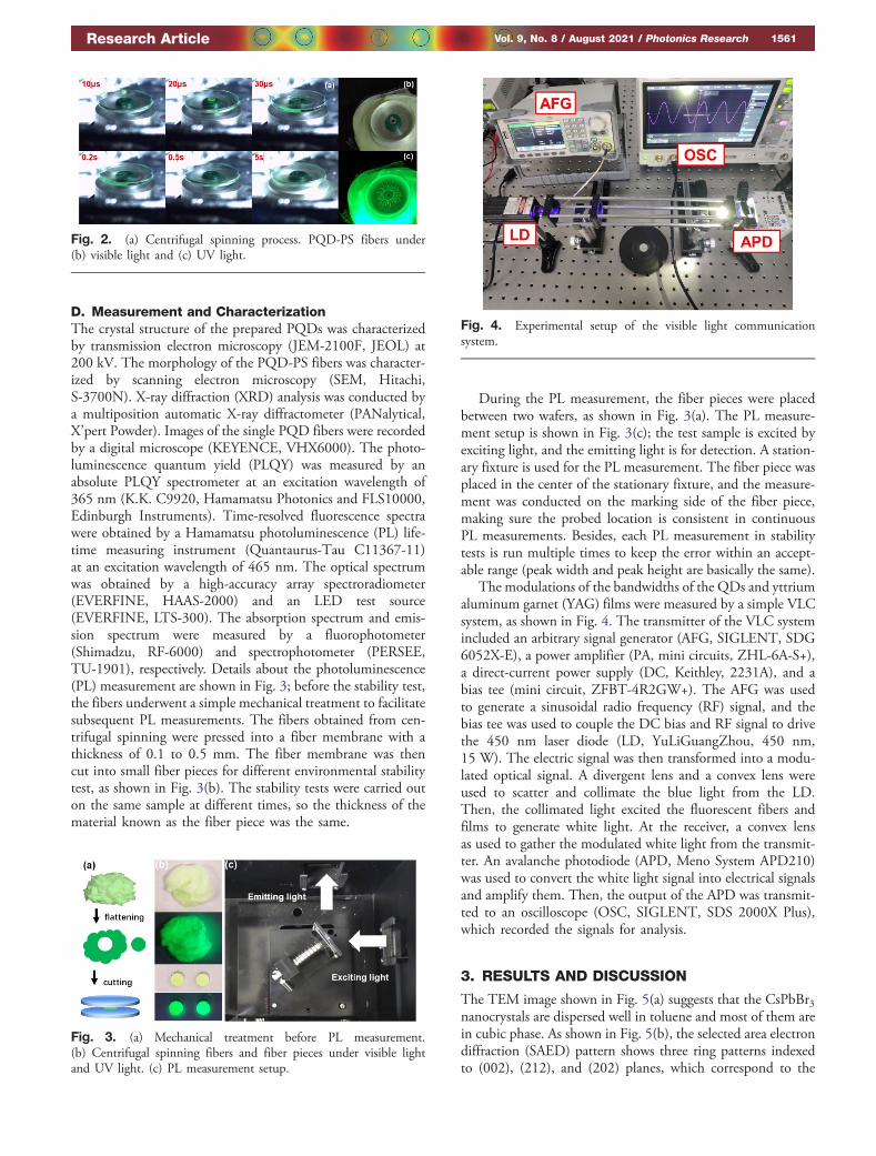
The modulations of the bandwidths of the QDs and yttriumaluminum garnet (YAG) films were measured by a simple VLCsystem, as shown in Fig. 4. The transmitter of the VLC systemincluded an arbitrary signal generator (AFG, SIGLENT, SDG6052X-E), a power amplifier (PA, mini circuits, ZHL-6A-S+),a direct-current power supply (DC, Keithley, 2231A), and abias tee (mini circuit, ZFBT-4R2GW+). The AFG was usedto generate a sinusoidal radio frequency (RF) signal, and thebias tee was used to couple the DC bias and RF signal to drivethe 450 nm laser diode (LD, YuLiGuangZhou, 450 nm,15 W). The electric signal was then transformed into a modu-lated optical signal. A divergent lens and a convex lens wereused to scatter and collimate the blue light from the LD.Then, the collimated light excited the fluorescent fibers andfilms to generate white light. At the receiver, a convex lensas used to gather the modulated white light from the transmit-ter. An avalanche photodiode (APD, Meno System APD210)was used to convert the white light signal into electrical signalsand amplify them. Then, the output of the APD was transmit-ted to an oscilloscope (OSC, SIGLENT, SDS 2000X Plus),which recorded the signals for analysis.
3. RESULTS AND DISCUSSION
The TEM image shown in Fig. 5(a) suggests that the CsPbBr3nanocrystals are dispersed well in toluene and most of them arein cubic phase. As shown in Fig. 5(b), the selected area electrondiffraction (SAED) pattern shows three ring patterns indexedto (002), (212), and (202) planes, which correspond to the
Fig. 3. (a) Mechanical treatment before PL measurement.(b) Centrifugal spinning fibers and fiber pieces under visible lightand UV light. (c) PL measurement setup.
Fig. 2. (a) Centrifugal spinning process. PQD-PS fibers under(b) visible light and (c) UV light.
Fig. 4. Experimental setup of the visible light communicationsystem.
Research Article Vol. 9, No. 8 / August 2021 / Photonics Research 1561

diffraction peaks at 30.38°, 34.47°, and 43.69° in the XRDpatterns of PQD-PS fibers [Fig. 6(b)]. The SAED pattern re-veals polycrystalline diffraction feature from CsPbBr3, sug-gesting a well-defined crystalline structure. The fast Fouriertransformation (FFT) image in Fig. 5(c) also shows cubicand rectangular shapes of the CsPbBr3 crystal. The high-reso-lution TEM (HRTEM) image shown in Fig. 5(c) further re-veals lattice spacings of 0.58 nm, which is in goodagreement with the (100) lattice spacing of cubic CsPbBr3[12,38,39]. A microscope image of a single PQD-PS fiber isshown in the inset of Fig. 6(c). The CsPbBr3 PQDs are coveredby PS fibers, as shown in the image of fibers under ultravioletlight because they are well protected during water immersion.Figure 6(a) shows the SEM image of the PQDs-PS fibers. Theaverage diameter of the fabricated fibers is approximately 3–5 μm. The X-ray diffraction patterns of PS fibers and PQD-PS fibers are shown in Fig. 6(b). The broad diffraction peakscan be ascribed to the amorphous PS fibers, and the detectedmain peaks at 21.5°, 26.4°, 28.6°, 30.4°, 34.5° and 43.7° cor-respond to the characteristic peaks of CsPbBr3 (PDF CardNo. 18-0346), confirming the presence of CsPbBr3 PQDswithin the PS fibers. However, except for the peaks ofCsPbBr3, the PQD-PS fibers show extra peaks at 22.58°,25.55°, 27.75°, and 28.81°. These peaks correspond toCs4PbBr6 (JCPDS 54-0750) and will be analyzed in the
following discussion. The time-resolved fluorescence measure-ment of the CsPbBr3 PQDs is shown in Fig. 6(c). The mea-sured PL decay kinetics is fitted with a double exponentialfunction of time (t):
I�t� � a1 exp
�−tτ1
�� a2 exp
�−tτ2
�, (1)
where τi represents the decay time of the ith component and airepresents the amplitude of the ith component. The average PLlifetime (τav) was estimated with the τi and ai values from thefitted curves data according to Eq. (2):
τav �P
aiτ2iPaiτi
: (2)
The τ1 and τ2 are 8.81 and 35.69 ns, respectively, and theτav of the PQD-PS fibers is about 14.43 ns. In this work, thefluorescence lifetime is determined by the delay time of excitonsproduced by electron hole recombination. The τ1 and τ2 re-present the time of photons passing through the first and sec-ond channels, respectively. The photons in the first channelconduct a direct recombination, while the photons in the sec-ond pass through the defect layer before recombination. That iswhy the τ1 is generally smaller, and the τ2 is larger [40,41].Further, the fluorescence lifetime can be affected by many fac-tors such as defect density of the materials and particle sizeand state.
Previous work has pointed out that the PQDs showed adouble exponential PL decay in liquid state [21]. When it turnsinto a solid state, defects grow because of the loss of the ligandat the surface of the PQDs as the solvent evaporates. As thedefects grow during centrifugal spinning, they increase the re-combination time of the PQDs, which corresponds to thelarger τ2 in this work. Details about defect growth of thePQD-PS fibers will be stressed in the following discussion.
The absorption and emission spectra of PQD-PS fibers areshown in Fig. 6(d). The PQD-PS fibers show a notable absorp-tion peak at 314 nm, which is the characteristic absorptionpeak of Cs4PbBr6 NCs and will be explained in the followingdiscussion. The emission peak of the PQD-PS fibers is centeredat 517 nm, which is similar to that in a previous study [21].
The time-dependent emission spectra of the PQD-PS fibersexposed to air are shown in Fig. 7(a). During the first two days,the emission intensity of the PQDs decreased by 25%. The fastdecline in the PL intensity in the first two days can be explainedby the centrifugal spinning method. Because the PQD-PS col-loid used in centrifugal spinning is prepared in advance, part ofthe CsPbBr3 QDs are inevitably exposed and absorbed to thefiber surface during centrifugal spinning. CsPbBr3 QDs aresensitive to moisture and oxygen, which destroy PQD crystals.The PL intensity of the PQDs decreased by 25% in the firsttwo days, which can be attributed to the degradation of thePQDs at the fiber surface, which is directly exposed to air.As the degradation of the PQDs occurred at the fiber surface,the decomposition products of the degradation process werealso absorbed on the surface. These decomposition productswill further reduce the light emission efficiency. The PQDs in-side the fibers are protected from aging by environmental fac-tors, corresponding to an almost unchanged emission intensity
Fig. 5. Structural analyses ofCsPbBr3 synthesized by ultrasonic syn-thesis. (a) TEM image ofCsPbBr3. (b) SAED pattern. (c) FFT pattern,HRTEM, and corresponding interplanar spacing.
Fig. 6. (a) SEM image of PQD fibers. (b) XRD patterns of PS andPQD-PS fibers. (c) Time-resolved fluorescence measurement of thePQD-PS fibers (inset: single PQD fiber under ambient light andUV light). (d) Absorption and emission spectra of PQD-PS fibers.
1562 Vol. 9, No. 8 / August 2021 / Photonics Research Research Article
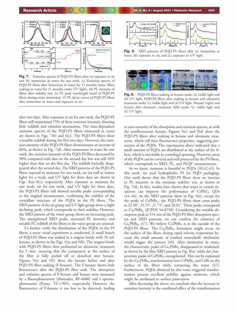
after two days. After exposure to air for one week, the PQD-PSfibers still maintained 75% of their emission intensity, showinglittle redshift and emission attenuation. The time-dependentemission spectra of the PQD-PS fibers immersed in waterare shown in Figs. 7(b) and 6(c). The PQD-PS fibers showa notable redshift during the first two days. However, the emis-sion intensity of the PQD-PS fibers demonstrates an increase of66%, as shown in Fig. 7(d). After immersion in water for oneweek, the emission intensity of the PQD-PS fibers decreased by30% compared with that on the second day but was still 16%higher than that on the first day. The redshift basically disap-peared after the second day. The XRD patterns of the PQD-PSfibers exposed to moisture for one week, air (as well as indoorlight) for a week, and UV light for three days are shown inFigs. 8(a)–8(c), respectively. After exposure to moisture forone week, air for one week, and UV light for three days,the PQD-PS fibers still showed notable peaks correspondingto the original measurement, confirming the stability of thecrystalline structure of the PQDs in the PS fibers. TheXRD patterns of the air group and UV light group show a slightdeclining peak, which corresponds to their stability. However,the XRD pattern of the water group shows an increasing peak.The strengthened XRD peaks, increased PL intensity, andnotable PL redshift of the fibers in the water group are unusual.
To further verify the distribution of the PQDs in the PSfibers, a more visual experiment is conducted. A small bunchof PQD-PS fibers was soaked in a reagent bottle with 10 mLhexane, as shown in the Figs. 9(a) and 9(b). The reagent bottlewith PQD-PS fibers then performed an ultrasonic treatmentfor 5 min, ensuring that the component at the surface ofthe fiber is fully peeled off or dissolved into hexane.Figures 9(e) and 9(f ) show the hexane before and afterPQD-PS fiber soaking (F-hexane). The F-hexane shows littlefluorescence after the PQD-PS fiber soak. The absorptionand emission spectra of F-hexane and hexane were measuredby a fluorophotometer (Shimadzu, RF-6000) and a spectro-photometer (Persee, TU-1901), respectively. However, thefluorescence of F-hexane is too low to be detected, leading
to zero intensity of the absorption and emission spectra, as withthe nonfluorescent hexane. Figures 9(c) and 9(d) show thePQD-PS fibers after soaking in hexane and ultrasonic treat-ment, which still have fluorescence properties, suggesting pro-tection of the PQDs. The experiments above indicated that asmall amount of PQDs are distributed at the surface of the fi-bers, which is inevitable in centrifugal spinning. However, mostof the PQDs can be covered and well protected by the PS fibers,which corresponds to XRD, PL, and PLQY measurements.
As we knew, moisture is harmful to PQDs [38,42,43]. Inthis work, we used hydrophobic PS for PQD packaging.Our work shows that the PQD-PS fibers show an increasein PL intensity in the moisture stability test, as shown inFig. 7(d). In fact, studies have shown that water in certain sit-uations can improve the performance of CsPbX3 QDs[44–46]. As the XRD patterns show in Fig. 8(a), except forthe peaks of CsPbBr3, the PQD-PS fibers show extra peaksat 22.58°, 25.55°, 27.75°, and 28.81°. These peaks correspondto Cs4PbBr6 (JCPDS 54-0750). Considering the notable ab-sorption peak at 314 nm of the PQD-PS fiber absorption spec-tra and XRD patterns, we can confirm the existence ofCs4PbBr6 [47]. We believe Cs4PbBr4 is at the outside of thePQD-PS fibers. The Cs4PbBr6 formation might occur onthe surface of the fibers during rapid solvent evaporation be-cause the small amount of residual nonvolatile oleylaminewould trigger the process [48]. After immersion in water,the characteristic peaks of Cs4PbBr6 disappeared or weakened,as shown by the blue XRD pattern in Fig. 8(a), while the char-acteristic peaks of CsPbBr3 strengthened. This can be explainedby the Cs4PbBr6 transformation into CsPbBr3 and CsBr on thesurface of the fibers while contacting the water [47].Furthermore, PQDs obtained by this water-triggered transfor-mation present excellent stability against moisture, whichmight be attributed to surface passivation.
After discussing the above, we conclude that the increase inemission intensity is the combined effect of the transformation
Fig. 7. Emission spectra of PQD-PS fibers after (a) exposure to airand (b) immersion in water for one week. (c) Emission spectra ofPQD-PS fibers after immersion in water for 11 months (inset: fiberssoaking in water for 11 months under UV light). (d) PL intensity offibers after stability test. (e) PL peak wavelength trend of PQD-PSfibers during water immersion. (f ) PL decay curves of PQD-PS fibersafter immersion in water and exposure to air.
Fig. 8. XRD patterns of PQD-PS fibers after (a) immersion inwater, (b) exposure to air, and (c) exposure to UV light.
Fig. 9. PQD-PS fibers soaking in hexane under (a) visible light and(b) UV light. PQD-PS fibers after soaking in hexane and ultrasonictreatment under (c) visible light and (d) UV light. Hexane (right) andhexane after ultrasonic treatment (left) under (e) visible light and(f ) UV light.
Research Article Vol. 9, No. 8 / August 2021 / Photonics Research 1563
from Cs4PbBr6 to CsPbBr3 and surface defect dissolution.Because Cs4PbBr6 is nonluminous, the transformation fromCs4PbBr6 to luminous CsPbBr3 and the water-assented surfacepassivation of the CsPbBr3 PQDs on the fiber surface contrib-ute to the PL increase in the fibers during the first two days afterimmersion in water. As the surface perovskite continues to dis-solve in water, the decrease in the PL intensity corresponding tothe decrease in the PL intensity of the water group after a shorttime increases, as shown in Fig. 7(d). Nevertheless, there wasnotable PL intensity increase after long-term water immersion,which could be explained by the enhancement in the light-outefficiency. During the centrifugal spinning process, part of theCsPbBr3 PQDs are absorbed on the surface of the fibers. ThesePQDs are directly exposed to air and light, and some of themare destroyed, forming nonluminous decomposition products.These nonluminous ingredients and Cs4PbBr6 are absorbed onthe surface of the fibers as defect layers, which directly reducesthe light emission efficiency of the fibers in the first PL mea-surement. As shown in Fig. 7(f ), the double exponential PLdecay of the PQD-PS fibers can be explained by the longerrecombination time of the quantum dots caused by the surfacedefects that formed during spinning. After immersion in waterfor one week, the fluorescence lifetime of the PQD-PS fibersdecreased, and the PL decay curve was closer to a single-exponential fitting. The PL decay decline is attributed tothe dissolution of the defects and corresponds to a previousstudy [48].
The PL intensity peak of the PQD-PS fibers redshifted from517 to 530 nm, accounting for a total redshift of 13 nm, asshown in Fig. 7(e). As the PL measurement in Fig. 7(a) shows,the redshift only occurred in the water-immersion group.Moisture-assisted crystal growth has previously been confirmedin various crystal systems, including CsPbBr3 [44,45,49]. Webelieve that moisture is the main cause of the redshift in thePQD-PS fibers. As the PL measurement shows in Fig. 7(b),the PQD-PS fibers are absolutely contained in the PS fibersbecause there is no notable perovskite hydrolysis during waterimmersion. The immersion of PQD-PS fibers in water mightresult in a small amount of moisture permeation within grainboundaries, inducing grain boundary creep and subsequentlymerging adjacent grains together [45]. The XRD pattern ofthe PQD-PS fibers in Fig. 8(a) shows the sharper diffractionpeaks (the main peaks of JCPDS 18-0364) of CsPbBr3, whichconfirms the improved crystallinity of the perovskite structurein PQD-PS fibers after water immersion and corresponds toRefs. [44,45].
The PL peak wavelength trend of the PQD-PS fibers isshown in Fig. 7(e). Through the PL peak wavelength trend,we can further understand the moisture erosion process.The PL peak shows a slight redshift during the first 10 h, whichmeans that crystal growth did not start at this point. One rea-sonable explanation for this is that the transformation fromCs4PbBr6 to CsPbBr3 and the surface defect dissolution onthe fiber surface slow moisture erosion. From 10 to 24 h,the PQD-PS fibers exhibit a notable redshift and then tendto be stable after 48 h, suggesting that the crystal growth ofthe PQDs continues for 10 to 20 h. The above trend suggeststhat the growth of CsPbBr3 was not completed, even in the PS
colloid, and could be triggered in certain conditions, such asmoisture. There might be small account of moisture in thePQD-PS fibers due to some gaps, which would facilitatethe crystal growth of PQDs and lead to a redshift. However, theimmersed moisture did not destroy the PQDs, suggesting theeffectiveness of the centrifugal spinning strategy and ability toprotect PQDs from water, even after 11 months of water im-mersion. This growth of CsPbBr3 crystals directly caused theredshift, and we are doing further research on the mechanism ofcrystal growth. We believe this growth will be suppressed oreliminated by adopting a better method of CsPbBr3 crystalsynthesis.
As discussed, inhibiting the formation of Cs4PbBr6 on thesurface of PQD-PS fibers can fundamentally reduce the changeof PL intensity on the fiber surface. The CsPbBr3 to Cs4PbBr6transformation depends on the concentration of bromide ionand oleylamine [47,48]. Thus, the transformation process canbe suppressed by optimizing the concentration of the originalcompound of PQDs synthesis. In addition, the CsPbBr3 QDsinevitably remaining at the fiber surface during centrifugal spin-ning can be removed by water or hexane washing before appli-cation, which can further guarantee their stability.
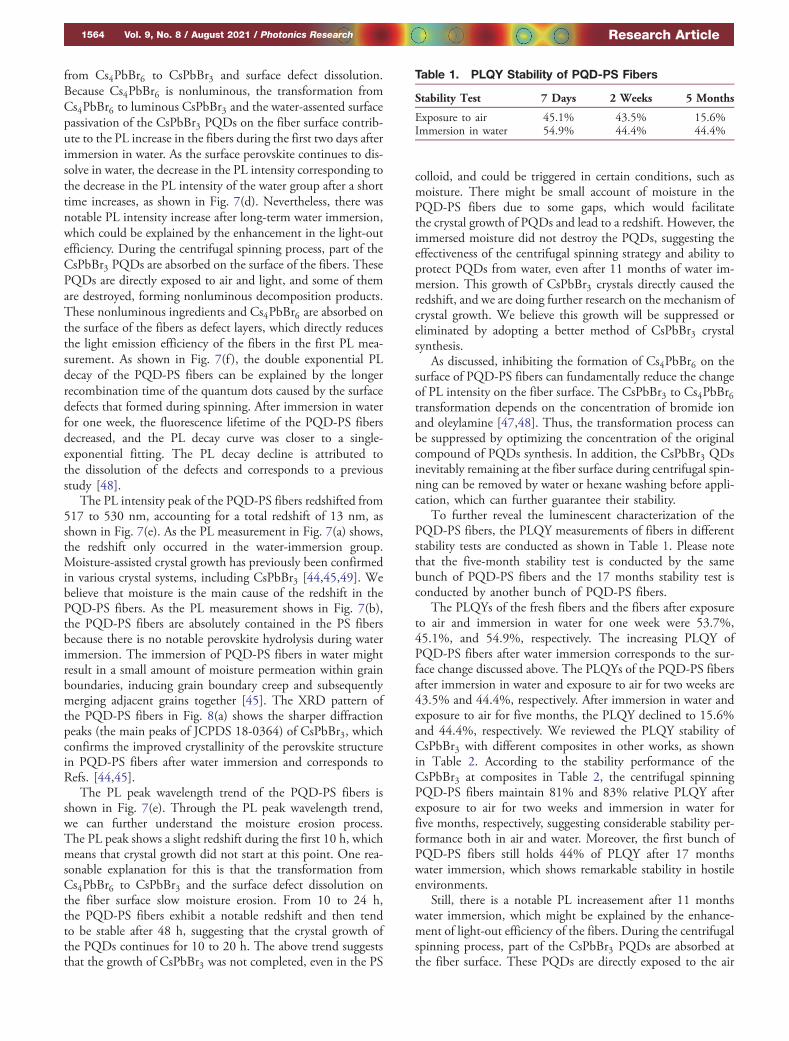
To further reveal the luminescent characterization of thePQD-PS fibers, the PLQY measurements of fibers in differentstability tests are conducted as shown in Table 1. Please notethat the five-month stability test is conducted by the samebunch of PQD-PS fibers and the 17 months stability test isconducted by another bunch of PQD-PS fibers.
The PLQYs of the fresh fibers and the fibers after exposureto air and immersion in water for one week were 53.7%,45.1%, and 54.9%, respectively. The increasing PLQY ofPQD-PS fibers after water immersion corresponds to the sur-face change discussed above. The PLQYs of the PQD-PS fibersafter immersion in water and exposure to air for two weeks are43.5% and 44.4%, respectively. After immersion in water andexposure to air for five months, the PLQY declined to 15.6%and 44.4%, respectively. We reviewed the PLQY stability ofCsPbBr3 with different composites in other works, as shownin Table 2. According to the stability performance of theCsPbBr3 at composites in Table 2, the centrifugal spinningPQD-PS fibers maintain 81% and 83% relative PLQY afterexposure to air for two weeks and immersion in water forfive months, respectively, suggesting considerable stability per-formance both in air and water. Moreover, the first bunch ofPQD-PS fibers still holds 44% of PLQY after 17 monthswater immersion, which shows remarkable stability in hostileenvironments.
Still, there is a notable PL increasement after 11 monthswater immersion, which might be explained by the enhance-ment of light-out efficiency of the fibers. During the centrifugalspinning process, part of the CsPbBr3 PQDs are absorbed atthe fiber surface. These PQDs are directly exposed to the air
Table 1. PLQY Stability of PQD-PS Fibers
Stability Test 7 Days 2 Weeks 5 Months
Exposure to air 45.1% 43.5% 15.6%Immersion in water 54.9% 44.4% 44.4%
1564 Vol. 9, No. 8 / August 2021 / Photonics Research Research Article
and light, and part of them are destroyed into nonluminousdecomposition products. These nonluminous ingredientsand the Cs4PbBr6 are absorbed on the fiber surface as defectlayers, which directly reduce the light emission efficiency of thefibers in the first PL measurement. Therefore, the PL intensityof the PQD-PS fibers obtained in the first measurement isextremely likely to be underestimated. Furthermore, thePLQY of the PQD-PS fibers can better describe the fluores-cence characteristic change during the water stability test.The original PLQY of the PQD-PS fibers is 53.7%. Afterone week water immersion, the PLQY increases to 54.9%,which corresponds to the surface change of the fibers, as dis-cussed in the paper. After two weeks’ water immersion, thePLQY declines to 44.4% and maintains a high level afterfive months’ water immersion, which corresponds to the com-pleted dissolution of the fluorescent substance at the fiber sur-face. We can conclude that the 44.4% PLQY is derived entirelyfrom the CsPbBr3 quantum dots within the fibers. Moreover,the first bunch of PQD-PS fibers still holds 44% of PLQY after17 months water immersion, which also confirms the abovediscussion about the surface dissolution.
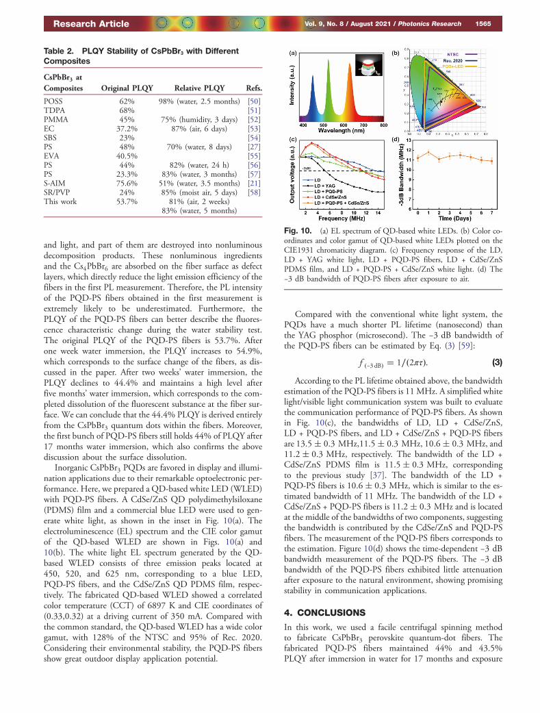
Inorganic CsPbBr3 PQDs are favored in display and illumi-nation applications due to their remarkable optoelectronic per-formance. Here, we prepared a QD-based white LED (WLED)with PQD-PS fibers. A CdSe/ZnS QD polydimethylsiloxane(PDMS) film and a commercial blue LED were used to gen-erate white light, as shown in the inset in Fig. 10(a). Theelectroluminescence (EL) spectrum and the CIE color gamutof the QD-based WLED are shown in Figs. 10(a) and10(b). The white light EL spectrum generated by the QD-based WLED consists of three emission peaks located at450, 520, and 625 nm, corresponding to a blue LED,PQD-PS fibers, and the CdSe/ZnS QD PDMS film, respec-tively. The fabricated QD-based WLED showed a correlatedcolor temperature (CCT) of 6897 K and CIE coordinates of(0.33,0.32) at a driving current of 350 mA. Compared withthe common standard, the QD-based WLED has a wide colorgamut, with 128% of the NTSC and 95% of Rec. 2020.Considering their environmental stability, the PQD-PS fibersshow great outdoor display application potential.
Compared with the conventional white light system, thePQDs have a much shorter PL lifetime (nanosecond) thanthe YAG phosphor (microsecond). The −3 dB bandwidth ofthe PQD-PS fibers can be estimated by Eq. (3) [59]:
f �−3 dB� � 1∕�2πτ�: (3)
According to the PL lifetime obtained above, the bandwidthestimation of the PQD-PS fibers is 11 MHz. A simplified whitelight/visible light communication system was built to evaluatethe communication performance of PQD-PS fibers. As shownin Fig. 10(c), the bandwidths of LD, LD + CdSe/ZnS,LD + PQD-PS fibers, and LD + CdSe/ZnS + PQD-PS fibersare 13.5� 0.3 MHz,11.5� 0.3 MHz, 10.6� 0.3 MHz, and11.2� 0.3 MHz, respectively. The bandwidth of the LD +CdSe/ZnS PDMS film is 11.5� 0.3 MHz, correspondingto the previous study [37]. The bandwidth of the LD +PQD-PS fibers is 10.6� 0.3 MHz, which is similar to the es-timated bandwidth of 11 MHz. The bandwidth of the LD +CdSe/ZnS + PQD-PS fibers is 11.2� 0.3 MHz and is locatedat the middle of the bandwidths of two components, suggestingthe bandwidth is contributed by the CdSe/ZnS and PQD-PSfibers. The measurement of the PQD-PS fibers corresponds tothe estimation. Figure 10(d) shows the time-dependent −3 dBbandwidth measurement of the PQD-PS fibers. The −3 dBbandwidth of the PQD-PS fibers exhibited little attenuationafter exposure to the natural environment, showing promisingstability in communication applications.
4. CONCLUSIONS
In this work, we used a facile centrifugal spinning methodto fabricate CsPbBr3 perovskite quantum-dot fibers. Thefabricated PQD-PS fibers maintained 44% and 43.5%PLQY after immersion in water for 17 months and exposure
Fig. 10. (a) EL spectrum of QD-based white LEDs. (b) Color co-ordinates and color gamut of QD-based white LEDs plotted on theCIE1931 chromaticity diagram. (c) Frequency response of the LD,LD + YAG white light, LD + PQD-PS fibers, LD + CdSe/ZnSPDMS film, and LD + PQD-PS + CdSe/ZnS white light. (d) The−3 dB bandwidth of PQD-PS fibers after exposure to air.
Table 2. PLQY Stability of CsPbBr3 with DifferentComposites
CsPbBr3 atComposites Original PLQY Relative PLQY Refs.
POSS 62% 98% (water, 2.5 months) [50]TDPA 68% [51]PMMA 45% 75% (humidity, 3 days) [52]EC 37.2% 87% (air, 6 days) [53]SBS 23% [54]PS 48% 70% (water, 8 days) [27]EVA 40.5% [55]PS 44% 82% (water, 24 h) [56]PS 23.3% 83% (water, 3 months) [57]S-AIM 75.6% 51% (water, 3.5 months) [21]SR/PVP 24% 85% (moist air, 5 days) [58]This work 53.7% 81% (air, 2 weeks)
83% (water, 5 months)
Research Article Vol. 9, No. 8 / August 2021 / Photonics Research 1565
to air for two weeks, respectively, exhibiting considerable envi-ronmental stability. The water-stability mechanism of the fiberscan be explained by the changing defect density, crystal growthof PQDs, and the molecular transformation at the fiber surface.Considering the remarkable photoelectric performance ofCsPbBr3 PQDs, a WLED was manufactured by the PQD-PS fibers. The WLED shows satisfying performance, with awide color gamut (128% of NTSC and 95% of Rec. 2020),a CCT of 6897 K, and CIE coordinates of (0.33,0.32).Furthermore, a white light/visible light communication systemwas built based on the PQD-PS fibers. The PQD-PS fiberswith the CdSe/ZnS QD white light system present a −3 dBbandwidth of 11.2 MHz, which is much higher than thatof the conventional YAG white light system. After exposureto air for one week, the bandwidth of the PQD-PS fibers ex-hibited no attenuation. The environmental stability and con-siderable performance of PQD-PS fibers show great potential indual display and communication applications.
Funding. National Natural Science Foundation of China(51805173, 51533003); Natural Science Foundation ofGuangdong Province (2019A1515011741); The Science andTechnology Program of Guangzhou (201904010252); TheProject of the National and Local Joint EngineeringResearch Center of Semiconductor Display and OpticalCommunication (Zhongshan Branch) (190919172214566).
Acknowledgment. The authors would like to acknowl-edge Guangdong University Students Special Funds for scien-tific and technological innovation cultivation and alsoacknowledge Cunjiang Song, Guanwei Liang, Yaoxing Song,Kejian Wu, Yongjun Chen, Jiexin Li, Longshi Rao, andChangkun Shao from South China University of Technologyand Jieyuan Wang from Shaanxi Normal University for exper-imental guidance and help, Peisheng Chen from GuangdongOcean University for image rendering, and good care fromMiss Yaqin.
Disclosures. The authors declare no conflicts of interest.
Data availability. Data underlying the results presentedin this paper are available in Dataset 1, Ref. [60].
REFERENCES1. L. Protesescu, S. Yakunin, M. I. Bodnarchuk, F. Krieg, R. Caputo,
C. H. Hendon, R. X. Yang, A. Walsh, and M. V. Kovalenko,“Nanocrystals of cesium lead halide perovskites (CsPbX3, X = Cl,Br, and I): novel optoelectronic materials showing bright emission withwide color gamut,” Nano Lett. 15, 3692–3696 (2015).
2. M. V. Kovalenko, L. Protesescu, and M. I. Bodnarchuk, “Propertiesand potential optoelectronic applications of lead halide perovskitenanocrystals,” Science 358, 745–750 (2017).
3. X. Gong, M. Li, X. B. Shi, H. Ma, Z. K. Wang, and L. S. Liao,“Controllable perovskite crystallization by water additive for high-performance solar cells,” Adv. Funct. Mater. 25, 6671–6678 (2015).
4. J. Z. Song, J. H. Li, X. M. Li, L. M. Xu, Y. H. Dong, and H. B. Zeng,“Quantum dot light-emitting diodes based on inorganic perovskitecesium lead halides (CsPbX3),” Adv. Mater. 27, 7162–7167 (2015).
5. Z. T. Li, K. Cao, J. S. Li, X. W. Du, Y. Tang, and B. H. Yu, “Modificationof interface between PEDOT:PSS and perovskite film inserting an
ultrathin LiF layer for enhancing efficiency of perovskite light-emittingdiodes,” Org. Electron. 81, 105675 (2020).
6. H. M. Zhu, Y. P. Fu, F. Meng, X. X. Wu, Z. Z. Gong, Q. Ding, M. V.Gustafsson, M. T. Trinh, S. Jin, and X. Y. Zhu, “Lead halide perovskitenanowire lasers with low lasing thresholds and high quality factors,”Nat. Mater. 14, 636–642 (2015).
7. S. F. Leung, K. T. Ho, P. K. Kung, V. K. S. Hsiao, H. N. Alshareef, Z. L.Wang, and J. H. He, “A self-powered and flexible organometallic hal-ide perovskite photodetector with very high detectivity,” Adv. Mater.30, 1704611 (2018).
8. R. H. Liu, J. Q. Zhang, H. Zhou, Z. H. Song, Z. N. Song, C. R. Grice,D. J. Wu, L. P. Shen, and H. Wang, “Solution-processed high-qualitycesium lead bromine perovskite photodetectors with high detectivityfor application in visible light communication,” Adv. Opt. Mater. 8,1901735 (2020).
9. N. Strobel, N. Droseros, W. Kontges, M. Seiberlich, M. Pietsch, S.Schlisske, F. Lindheimer, R. R. Schroder, U. Lemmer, M.Pfannmoller, N. Banerji, and G. Hernandez-Sosa, “Color-selectiveprinted organic photodiodes for filterless multichannel visible lightcommunication,” Adv. Mater. 32, 1908258 (2020).
10. W. H. Li, S. B. Li, L. Duan, H. J. Chen, L. D. Wang, G. F. Dong, andZ. Y. Xu, “Squarylium and rubrene based filterless narrowband photo-detectors for an all-organic two-channel visible light communicationsystem,” Org. Electron. 37, 346–351 (2016).
11. E. Lopez-Fraguas, B. Arredondo, C. Vega-Colado, G. del Pozo, M.Najafi, D. Martin-Martin, Y. Galagan, J. M. Sanchez-Pena, R.Vergaz, and B. Romero, “Visible light communication system usingan organic emitter and a perovskite photodetector,” Org. Electron.73, 292–298 (2019).
12. Y. Tong, E. Bladt, M. F. Ayguler, A. Manzi, K. Z. Milowska, V. A.Hintermayr, P. Docampo, S. Bals, A. S. Urban, L. Polavarapu, andJ. Feldmann, “Highly luminescent cesium lead halide perovskitenanocrystals with tunable composition and thickness by ultrasonica-tion,” Angew. Chem. 55, 13887–13892 (2016).
13. S. L. Mei, X. Y. Liu, W. L. Zhang, R. Liu, L. R. Zheng, R. Q. Guo, andP. F. Tian, “High-bandwidth white-light system combining a micro-LED with perovskite quantum dots for visible light communication,”ACS Appl. Mater. Interfaces 10, 5641–5648 (2018).
14. S. Jung, J. H. Kim, J. W. Choi, J. W. Kang, S. H. Jin, Y. Kang, and M.Song, “Enhancement of photoluminescence quantum yield andstability in CsPbBr3 perovskite quantum dots by trivalent doping,”Nanomaterials 10, 710 (2020).
15. S. L. Mei, B. B. Yang, X. Wei, H. Q. Dai, Z. H. Chen, Z. J. Cui, G. L.Zhang, F. X. Xie, W. L. Zhang, and R. Q. Guo, “Facile synthesis andoptical properties of CsPbX3/ZIF-8 composites for wide-color-gamutdisplay,” Nanomaterials 9, 832 (2019).
16. Z. T. Li, X. T. Tang, J. D. Yu, Y. Tang, B. H. Yu, Y. L. Hu, B. Liu, andX. R. Ding, “Lifetime enhancement of a circulated cooling perovskitequantum dots colloidal solution system for laser illuminations,” IEEEAccess 7, 136214–136222 (2019).
17. I. Dursun, C. Shen, M. R. Parida, J. Pan, S. P. Sarmah, D. Priante, N.Alyami, J. Liu, M. I. Saidaminov, M. S. Alias, A. L. Abdelhady, T. K. Ng,O. F. Mohammed, B. S. Ooi, and O. M. Bakr, “Perovskite nanocrystalsas a color converter for visible light communication,” ACS Photon. 3,1150–1156 (2016).
18. C. H. Lin, C. Y. Kang, A. Verma, T. Z. Wu, Y. M. Pai, T. Y. Chen, C. L.Tsai, Y. Z. Yang, S. K. Sharma, C. W. Sher, Z. Chen, P. T. Lee, S. R.Chung, and H. C. Kuo, “Ultrawide color gamut perovskite and CdSe/ZnS quantum-dots-based white light-emitting diode with high lumi-nous efficiency,” Nanomaterials 9, 1314 (2019).
19. H. Huang, M. I. Bodnarchuk, S. V. Kershaw, M. V. Kovalenko, andA. L. Rogach, “Lead halide perovskite nanocrystals in the researchspotlight: stability and defect tolerance,” ACS Energy Lett. 2, 2071–2083 (2017).
20. B. Hailegnaw, S. Kirmayer, E. Edri, G. Hodes, and D. Cahen, “Rain onmethylammonium lead iodide based perovskites: possible environ-mental effects of perovskite solar cells,” J. Phys. Chem. Lett. 6,1543–1547 (2015).
21. Z. T. Li, C. J. Song, J. S. Li, G. W. Liang, L. S. Rao, S. D. Yu, X. R.Ding, Y. Tang, B. H. Yu, J. Z. Ou, U. Lemmer, and G. Gomard, “Highlyefficient and water-stable lead halide perovskite quantum dots using
1566 Vol. 9, No. 8 / August 2021 / Photonics Research Research Article
superhydrophobic aerogel inorganic matrix for white light-emittingdiodes,” Adv. Mater. Technol. 5, 1900941 (2020).
22. J. S. Li, Y. Tang, Z. T. Li, X. R. Ding, B. H. Yu, and L. W. Lin, “Largelyenhancing luminous efficacy, color-conversion efficiency, and stabilityfor quantum-dot white LEDs using the two-dimensional hexagonalpore structure of SBA-15 mesoporous particles,” ACS Appl. Mater.Interfaces 11, 18808–18816 (2019).
23. Y. T. J.-S. Li, Z.-T. Li, J.-X. Li, X.-R. Ding, B.-H. Yu, S.-D. Yu, J.-Z. Ou,and H.-C. Kuo, “Toward 200 lumens per watt of quantum-dot white-light-emitting diodes by reducing reabsorption loss,” ACS Nano 15,550–562 (2021).
24. Y. Wei, X. R. Deng, Z. X. Xie, X. C. Cai, S. S. Liang, P. Ma, Z. Y. Hou,Z. Y. Cheng, and J. Lin, “Enhancing the stability of perovskite quantumdots by encapsulation in crosslinked polystyrene beads via a swelling-shrinking strategy toward superior water resistance,” Adv. Funct.Mater. 27, 1703535 (2017).
25. P. G. Papagiorgis, A. Manoli, A. Alexiou, P. Karacosta, X. Karagiorgis,G. Papaparaskeva, C. Bernasconi, M. I. Bodnarchuk, M. V.Kovalenko, T. Krasia-Christoforou, and G. Itskos, “Robust hydropho-bic and hydrophilic polymer fibers sensitized by inorganic and hybridlead halide perovskite nanocrystal emitters,” Front. Chem. 7, 87(2019).
26. L. H. Meng, C. G. Yang, J. J. Meng, Y. Z. Wang, Y. Ge, Z. Q. Shao,G. F. Zhang, A. L. Rogach, and H. Z. Zhong, “In-situ fabricated aniso-tropic halide perovskite nanocrystals in polyvinylalcohol nanofibers:shape tuning and polarized emission,” Nano Res. 12, 1411–1416(2019).
27. H. Liao, S. B. Guo, S. Cao, L. Wang, F. M. Gao, Z. B. Yang, J. J.Zheng, and W. Y. Yang, “A general strategy for in situ growth ofall-inorganic CsPbX3 (X = Br, I, and Cl) perovskite nanocrystals in pol-ymer fibers toward significantly enhanced water/thermal stabilities,”Adv. Opt. Mater. 6, 1800346 (2018).
28. H. H. Zhang, D. F. Fu, Z. T. Du, H. Fu, G. Shao, W. Y. Yang, and J. J.Zheng, “In situ growth of aligned CsPbBr3 nanorods in polymerfibers with tailored aspect ratios,” Ceram. Int. 46, 18352–18357(2020).
29. D. H. Jiang, S. Kobayashi, C. C. Jao, Y. Mato, T. Isono, Y. H. Fang,C. C. Lin, T. Satoh, S. H. Tung, and C. C. Kuo, “Light down-converterbased on luminescent nanofibers from the blending of conjugatedrod-coil block copolymers and perovskite through electrospinning,”Polymers 12, 84 (2020).
30. X. Lu, Y. Hu, J. Z. Guo, C. F. Wang, and S. Chen, “Fiber-spinning-chemistry method toward in situ generation of highly stable halideperovskite nanocrystals,” Adv. Sci. 6, 1901694 (2019).
31. T. T. Cui, Z. J. Zhu, R. Cheng, Y. L. Tong, G. Peng, C. F. Wang, and S.Chen, “Facile access to wearable device via microfluidic spinningof robust and aligned fluorescent microfibers,” ACS Appl. Mater.Interfaces 10, 30785–30793 (2018).
32. L. Y. Ron and S. P. Kotha, “Centrifugal jet spinning for highly efficientand large-scale fabrication of barium titanate nanofibers,” Mater. Lett.117, 153–157 (2014).
33. L. K. Hromadko, E. Koudelkova, R. Bulanek, and J. M. Macak, “SiO2
fibers by centrifugal spinning with excellent textural properties andwater adsorption performance,” ACS Omega 2, 5052–5059 (2017).
34. M. R. Badrossamay, H. A. McIlwee, J. A. Goss, and K. K. Parker,“Nanofiber assembly by rotary jet-spinning,” Nano Lett. 10, 2257–2261 (2010).
35. A. Barhoum, K. Pal, H. Rahier, H. Uludag, I. S. Kim, and M.Bechelany, “Nanofibers as new-generation materials: from spinningand nano-spinning fabrication techniques to emerging applications,”Appl. Mater. Today 17, 1–35 (2019).
36. E. Ercan, P.-C. Tsai, J.-Y. Chen, J.-Y. Lam, L.-C. Hsu, C.-C. Chueh,and W.-C. Chen, “Stretchable and ambient stable perovskite/polymerluminous hybrid nanofibers of multicolor fiber mats and their whiteLED applications,” ACS Appl. Mater. Interfaces 11, 23605–23615(2019).
37. B. H. L. Yu, S. Liang, X. Ding, Z. Li, and Y. Tang, “A sandwich struc-ture light-trapping fluorescence antenna with large field of view forvisible light communication,” IEEE Trans. Electron Dev. 68, 565–571 (2021).
38. A. Loiudice, S. Saris, E. Oveisi, D. T. L. Alexander, and R. Buonsanti,“CsPbBr3 QD/AlOx inorganic nanocomposites with exceptional stabil-ity in water, light, and heat,” Angew. Chem. 56, 10696–10701 (2017).
39. L. S. Rao, Y. Tang, C. J. Song, K. Xu, E. T. Vickers, S. B. Naghadeh,X. R. Ding, Z. T. Li, and J. Z. Zhang, “Polar-solvent-free synthesisof highly photoluminescent and stable CsPbBr3 nanocrystals with con-trolled shape and size by ultrasonication,” Chem. Mater. 31, 365–375(2019).
40. V. S. Chirvony, S. Gonzalez-Carrero, I. Suarez, R. E. Galian, M.Sessolo, H. J. Bolink, J. P. Martinez-Pastor, and J. Perez-Prieto,“Delayed luminescence in lead halide perovskite nanocrystals,”J. Phys. Chem. C 121, 13381–13390 (2017).
41. V. Malgras, J. Henzie, T. Takei, and Y. Yamauchi, “Stable blue lumi-nescent CsPbBr3 perovskite nanocrystals confined in mesoporousthin films,” Angew. Chem. 57, 8881–8885 (2018).
42. S. N. Raja, Y. Bekenstein, M. A. Koc, S. Fischer, D. Zhang, L. Lin,R. O. Ritchie, P. Yang, and A. P. Alivisatos, “Encapsulation of perov-skite nanocrystals into macroscale polymer matrices: enhanced sta-bility and polarization,” ACS Appl. Mater. Interfaces 8, 35523–35533(2016).
43. Y. Wei, Z. Y. Cheng, and J. Lin, “An overview on enhancing the sta-bility of lead halide perovskite quantum dots and their applications inphosphor-converted LEDs,” Chem. Soc. Rev. 48, 310–350 (2019).
44. S. Huang, Z. Li, B. Wang, N. Zhu, C. Zhang, L. Kong, Q. Zhang, A.Shan, and L. Li, “Morphology evolution and degradation of CsPbBr3nanocrystals under blue light-emitting diode illumination,” ACS Appl.Mater. Interfaces 9, 7249–7258 (2017).
45. J. B. You, Y. M. Yang, Z. R. Hong, T. B. Song, L. Meng, Y. S. Liu, C. Y.Jiang, H. P. Zhou, W. H. Chang, G. Li, and Y. Yang, “Moistureassisted perovskite film growth for high performance solar cells,”Appl. Phys. Lett. 105, 183902 (2014).
46. Y. Liu, F. Li, Q. Liu, and Z. Xia, “Synergetic effect of postsyntheticwater treatment on the enhanced photoluminescence and stabilityof CsPbX3 (X = Cl, Br, I) perovskite nanocrystals,” Chem. Mater.30, 6922–6929 (2018).
47. L. Wu, H. Hu, Y. Xu, S. Jiang, M. Chen, Q. Zhong, D. Yang, Q. Liu, Y.Zhao, B. Sun, Q. Zhang, and Y. Yin, “From nonluminescent Cs4PbX6
(X = Cl, Br, I) nanocrystals to highly luminescent CsPbX3 nanocrys-tals: water-triggered transformation through a CsX-stripping mecha-nism,” Nano Lett. 17, 5799–5804 (2017).
48. Z. Liu, Y. Bekenstein, X. Ye, S. C. Nguyen, J. Swabeck, D. Zhang,S.-T. Lee, P. Yang, W. Ma, and A. P. Alivisatos, “Ligand mediatedtransformation of cesium lead bromide perovskite nanocrystals tolead depleted Cs4PbBr6 nanocrystals,” J. Am. Chem. Soc. 139,5309–5312 (2017).
49. Y. N. Chen, M. H. He, J. J. Peng, Y. Sun, and Z. Q. Liang, “Structureand growth control of organic-inorganic halide perovskites for opto-electronics: from polycrystalline films to single crystals,” Adv. Sci.3, 1500392 (2016).
50. H. Huang, B. K. Chen, Z. G. Wang, T. F. Hung, A. S. Susha, H. Z.Zhong, and A. L. Rogach, “Water resistant CsPbX3 nanocrystalscoated with polyhedral oligomeric silsesquioxane and their use assolid state luminophores in all-perovskite white light-emitting devices,”Chem. Sci. 7, 5699–5703 (2016).
51. T. T. Xuan, X. F. Yang, S. Q. Lou, J. J. Huang, Y. Liu, J. B. Yu, H. L. Li,K. L. Wong, C. X. Wang, and J. Wang, “Highly stable CsPbBr3 quan-tum dots coated with alkyl phosphate for white light-emitting diodes,”Nanoscale 9, 15286–15290 (2017).
52. K. Z. Ma, X. Y. Du, Y. W. Zhang, and S. Chen, “In situ fabrication ofhalide perovskite nanocrystals embedded in polymer composites viamicrofluidic spinning microreactors,” J. Mater. Chem. C 5, 9398–9404(2017).
53. Y. H. Song, J. S. Yoo, B. K. Kang, S. H. Choi, E. K. Ji, H. S. Jung, andD. H. Yoon, “Long-term stable stacked CsPbBr3 quantum dot filmsfor highly efficient white light generation in LEDs,” Nanoscale 8,19523–19526 (2016).
54. C. C. Lin, D. H. Jiang, C. C. Kuo, C. J. Cho, Y. H. Tsai, T. Satoh, and C.Su, “Water-resistant efficient stretchable perovskite-embedded fibermembranes for light-emitting diodes,” ACS Appl. Mater. Interfaces10, 2210–2215 (2018).
Research Article Vol. 9, No. 8 / August 2021 / Photonics Research 1567

55. Y. Li, Y. Lv, Z. Q. Guo, L. B. Dong, J. H. Zheng, C. F. Chai, N. Chen,Y. J. Lu, and C. Chen, “One-step preparation of long-term stable andflexible CsPbBr3 perovskite quantum dots/ethylene vinyl acetatecopolymer composite films for white light-emitting diodes,” ACSAppl. Mater. Interfaces 10, 15888–15894 (2018).
56. Y. C. Wong, J. D. Ng, and Z. K. Tan, “Perovskite-initiated photopoly-merization for singly dispersed luminescent nanocomposites,” Adv.Mater. 30, 1800774 (2018).
57. D. H. Jiang, Y. H. Tsai, L. Veeramuthu, F. C. Liang, L. C. Chen, C. C.Lin, T. Satoh, S. H. Tung, and C. C. Kuo, “Novel ultra-stable and highlyluminescent white light-emitting diodes from perovskite quantumdots-polymer nanofibers through biaxial electrospinning,” APL Mater.7, 111105 (2019).
58. J. Hai, H. Li, Y. Zhao, F. J. Chen, Y. Peng, and B. D. Wang, “Designingof blue, green, and red CsPbX3 perovskitecodoped flexible filmswith water resistant property and elimination of anion-exchange fortunable white light emission,” Chem. Commun. 53, 5400–5403(2017).
59. Y. L. Zhang, M. J. Jiang, T. Han, X. T. Xiao, W. L. Chen, L. Wang, K. S.Wong, R. Wang, K. Wang, B. Z. Tang, and K. S. Wu, “Aggregation-induced emission luminogens as color converters for visible-lightcommunication,” ACS Appl. Mater. Interfaces 10, 34418–34426(2018).
60. S. Liang, “Original optical data of PQD-PS fibers,” https://doi.org/10.6084/m9.figshare.14748027.v1 (2021).
1568 Vol. 9, No. 8 / August 2021 / Photonics Research Research Article