water resources engineering civil engineering...
TRANSCRIPT

1
Water Treatment Technology
Water Resources EngineeringCivil Engineering
ENGC 6305
Dr. Fahid Rabah PhD. PE.
Lecture 2: Coagulation and Flocculation
PDF created with pdfFactory Pro trial version www.pdffactory.com

2
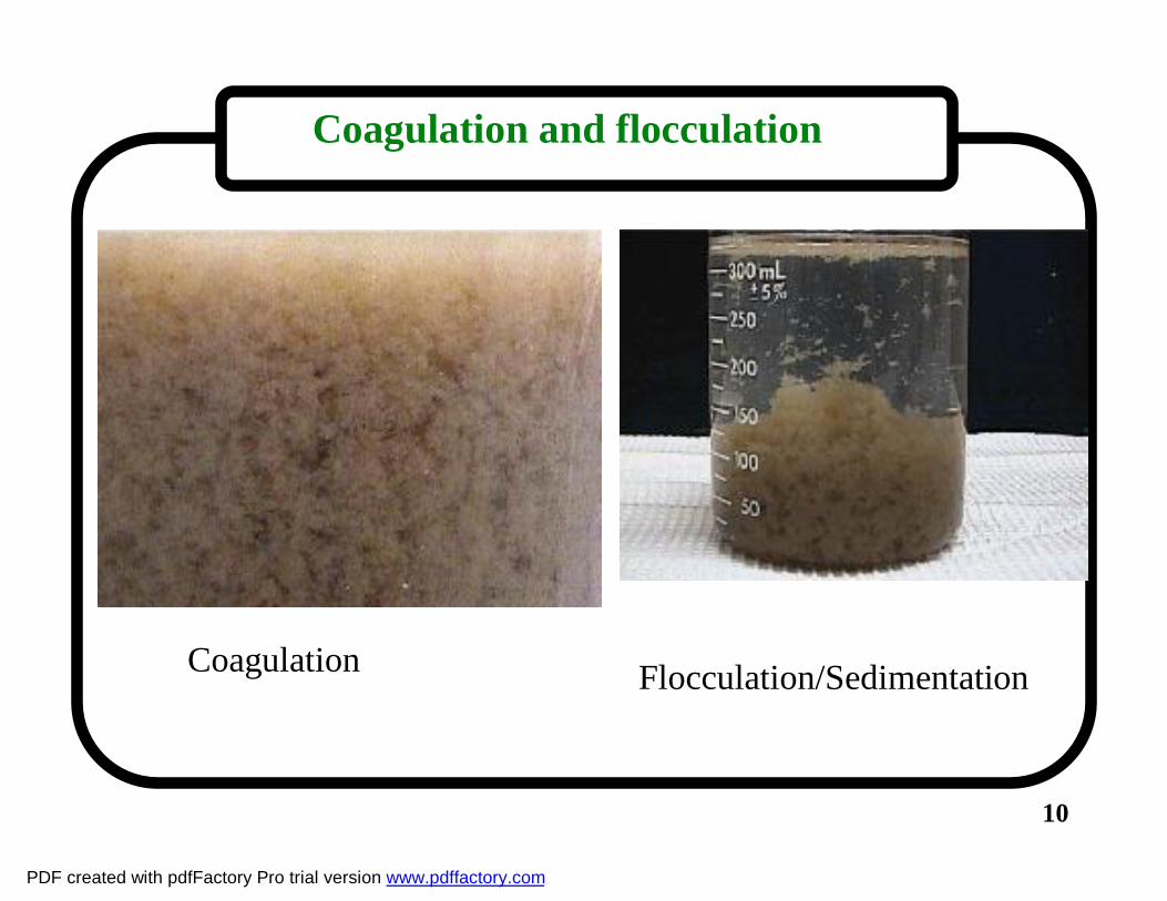
Coagulation and flocculation
1. Definitions:- Coagulation and flocculation are two consecutive process (i.e.
occur one after the other) that are used to remove colloidal particles from water.
- Colloids are very small particles (turbidity and color causing particles) that can not be removed neither by sedimentation (due to their light weight) nor by filtration. Examples of colloids: soil particles, bacteria, viruses and color causing materials. These colloids are stable in solution and theoretically will stay there for ever unless an action is done to destabilize them. Coagulation and flocculation are the two processes used for this destabilization.
PDF created with pdfFactory Pro trial version www.pdffactory.com

3
Particles Spectrum
Ultrafiltration CONVENTIONAL FILTRATION
Sands
Algae and protozoans
Bacteria
Colloids
Humicacids
Metal ions
Pesticides
Dissolved salts
Sugars
Molecularweight
Viruses
Angström
MICRON
IONSIONS MOLECULESMOLECULES MACRO MOLECULESMACRO MOLECULES MICRO PARTICLESMICRO PARTICLES MACRO PARTICLESMACRO PARTICLES
VISIBLE TO NAKED EYEVISIBLE TO NAKED EYEOPTICAL MICROSCOPEOPTICAL MICROSCOPESCANNING ELECTRON MICROSCOPESCANNING ELECTRON MICROSCOPE
Note : 1 Angström = 10-10 meter = 10-4 micron
Reverse Osmosis
Nanofiltration
Microfiltration
Figure 2.1
10-3 10-2 10-1
PDF created with pdfFactory Pro trial version www.pdffactory.com

4
Coagulation and flocculation
2. Colloidal Stability• Colloids are very Small particles (0.01 to 1 µm) • Most naturally occurring particles in water are negatively charged. Since like
charges repel, these small particles, or colloids, will remain suspended almost indefinitely.
• A fixed layer of positive ions (counterions) is attracted to the negatively charged colloids by electrostatic attraction. This layer is called stern layer or fixed layer. This layer is surrounded by a movable diffuse layer of counterions but with a lower concentration than that in the fixed layer. The two layers form what is called the double layer theory.
• The surface between the two layers is called the shear surface. When the colloid moves the fixed layer moves with it.
• The positive charge attached to the colloid in the stern layer is not enough to neutralize the negative charge of the colloid. So there is a net electrical potential around the colloid as shown in the Figure 2.2.
• The Electrical potential at the shear surface is called the Zeta potential which is a measure of the repulsive force of the colloid to other colloids having the same charge.
PDF created with pdfFactory Pro trial version www.pdffactory.com

5
Figure 2.2Double layer charges and Zeta potential around a colloid
PDF created with pdfFactory Pro trial version www.pdffactory.com

6
• There are two major forces acting on colloids: 1) Electrostatic repulsion negative colloids repel other negatively charged
colloids2) Intermolecular, or van der Waals, attraction.Figures 2.3 : Illustrates these two main forces.
For a stable colloid the net energy is repulsive.
Figures 2.4 (a): A stable suspension of particles where forces of repulsion exceed the forces of attraction
Coagulation and flocculation
PDF created with pdfFactory Pro trial version www.pdffactory.com

7
Coagulation and flocculation
Figure 2.3
PDF created with pdfFactory Pro trial version www.pdffactory.com

8
Figure 2.4
PDF created with pdfFactory Pro trial version www.pdffactory.com

9
Coagulation and flocculation
3. Coagulation (Colloidal Destabilization)- It is the process of destabilization the colloids by adding chemicals (Coagulants) with a counter charge to neutralize the charge carried by the colloids. This will reduce the repelling force and gives the opportunity for the attractive forces to prevail and allow the particles and make them ready to agglomerate and form bigger particles.
See Figure 2.4 (b): Destabilization caused by counterions of a coagulant which neutralize the negative ion of the colloid.
4. Flocculation ( Forming Flocs)After destabilization (i.e. Coagulation), particles will be ready to a tract and agglomerate and form flocs. But this agglomeration is slow and they need help to accelerate this agglomeration. This help is called Flocculation “which is the slow stirring or gentle agitation to aggregate the destabilized particles and form a rapid settling floc”. This gentle mixing increases the collisions between the particles and help them to agglomerate. Notice that rapid mixing will destroy the flocs, that's why we need gentle mixing.
We will discus flocculation later in this lecture. Lets now return back to Coagulation.
PDF created with pdfFactory Pro trial version www.pdffactory.com
10
Coagulation Flocculation/Sedimentation
Coagulation and flocculation
PDF created with pdfFactory Pro trial version www.pdffactory.com

11
Coagulation and flocculation
5. Coagulants:The chemicals added to water to destabilize colloids
are called Coagulants. The most common Coagulants used in water treatment are:
- Aluminum Sulfate (Alum): Al2(SO4)3⋅14H2O - Ferric Chloride : FeCl3 ⋅ xH2O- Ferric sulfate : Fe2(SO4)3 ⋅ xH2OTwo key properties of Coagulants• Should be nontoxic: health concern• Trivalent ions: most efficient compared to mono and
divalent.
PDF created with pdfFactory Pro trial version www.pdffactory.com

12
6. Coagulation chemistry:If Alum is used the following reactions occur:
• Al2(SO4)3⋅14H2O ↔ 2Al3++ 3SO42-+ 14H2O
• 2Al3+ + colloids ↔ neutralize surface charge
• 2Al3+ + 6HCO3- ↔ 2Al(OH)3(s) + 6CO2
• If insufficient bicarbonate is available:
Al2(SO4)3⋅14H2O ↔ 2Al(OH)3(s) + 3H2SO4 + 14H2O
• Optimum pH: 5.5 to 6.5
• Operating pH: 5 to 8
Coagulation and flocculation
PDF created with pdfFactory Pro trial version www.pdffactory.com

13
7. Factors affecting CoagulationThe two main factors affecting the coagulation process are: - Coagulant dosage - pH of the waterThe optimum dosage and optimum pH are determined by
laboratory test called the Jar Test. the Jar test consists of six beakers filled with the water to be treated and then each is mixed and flocculated uniformly. A test is often conducted by first dosing each jar with the same value of coagulant and varying the pH of each jar. The test can then be repeated by holding the pH constant and varying the coagulant dosage.
See Figures 2.5 , 2.6 and 2.7.
Coagulation and flocculation
PDF created with pdfFactory Pro trial version www.pdffactory.com

14
Jar Test
Figure 2.5
PDF created with pdfFactory Pro trial version www.pdffactory.com

15
Optimum pH for coagulation
Figure 2.6
PDF created with pdfFactory Pro trial version www.pdffactory.com

16Figure 2.7 Optimum pH and optimum dose from the jar test
Optimum pH
Optimum dose
PDF created with pdfFactory Pro trial version www.pdffactory.com

17
8. Coagulation aidsCoagulation aids are chemicals that are added to inhance the coagulation process. Some examples of these chemicals are:
- pH adjusters: Alkalis : lime [Ca(OH)2] or Soda Ash [Na2CO3)] to lower the pHAcids : Sulfuric acid [ H2SO4] to raise the pH
- Inter-particle bridging aidsPolymers: long chained carbon compounds of high molecular weight
that join flocs together and forms a shape that looks like a bridge connecting many flock.
- Weight adding aidsactivated silica and clay. They are both negatively charged and attracted to the positive coagulant ions and help in increasing the weight of the flocs.
Coagulation and flocculation
PDF created with pdfFactory Pro trial version www.pdffactory.com

18
9. Coagulation and Rapid Mixing:- When coagulants are added to water in treatment plants, they
need to be mixed and dispersed instantly. The Coagulation reaction takes place in very low time less than 1 second.
- Coagulation occurs in a rapid mixing tank such as those shown in Figure 2.8.
- Rapid mixing may also be achieved using hydraulic jump mixing as shown in Figures 2.9 and 2.10.
- See also Figures 2.10,2.11 and 2.12
Coagulation and flocculation
PDF created with pdfFactory Pro trial version www.pdffactory.com

19
Rapid Mixing Tanks
Figure 2.8
PDF created with pdfFactory Pro trial version www.pdffactory.com

20
Hydraulic Jump Mixer
Figure 2.9
PDF created with pdfFactory Pro trial version www.pdffactory.com

21
Hydraulic Jump Mixer
21
Hydraulic Jump Mixer
Figure 2.10
PDF created with pdfFactory Pro trial version www.pdffactory.com

22
ImpellerMixer
22Figure 2.11
PDF created with pdfFactory Pro trial version www.pdffactory.com

23
Mechanical Flash Mixer
23Figure 2.12
PDF created with pdfFactory Pro trial version www.pdffactory.com

24
Various Impeller Shapes
24
Figure 2.13
PDF created with pdfFactory Pro trial version www.pdffactory.com

25
Surface water from supply
Rapid Mix
FlocculationBasin
Sedimentationbasin
SludgeRapid Sand Filter
Disinfection
Storage
To DistributionSystem
Screen
Coagulation and flocculation
Figure 2.9
PDF created with pdfFactory Pro trial version www.pdffactory.com

26
10. Flocculation ( Forming Flocs)-After destabilization (i.e. Coagulation), particles will be ready to a tract and agglomerate and form flocs. But this agglomeration is slow and they need help to accelerate this agglomeration. - This help is called Flocculation “which is the slow stirring or gentle agitation to aggregate the destabilized particles and form a rapid settling floc”. This gentle mixing increases the collisions between the particles and help them to agglomerate. Notice that rapid mixing will destroy the flocs, that's why we need gentle mixing.
- Flocculation occurs in a tank called a Flocculator or Flocculation Basin equipped with a method for Slow Mixing. The most common types of Flocculators are shown in the following slides.
Coagulation and flocculation
PDF created with pdfFactory Pro trial version www.pdffactory.com

27
Flocculator Types
11. Flocculator Types
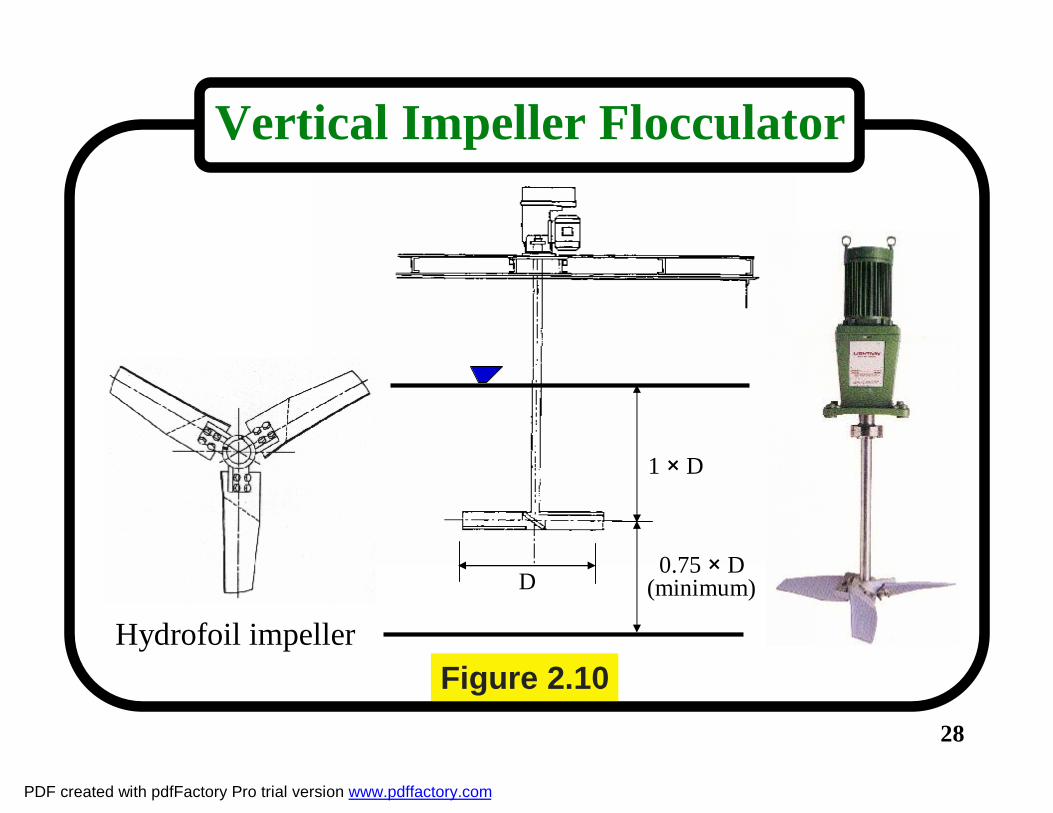
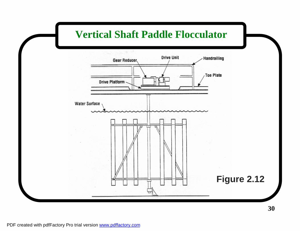
A. Mechanical Mixing Flocculators-Vertical shaft with impeller (turbine or propeller type blades)-Paddle type with either horizontal or vertical shafts- Walking Beam Flocculator
B. Hydraulic Mixing Baffled Channels Flocculators-Horizontal baffled channels-Vertically baffled channel
PDF created with pdfFactory Pro trial version www.pdffactory.com
28
Vertical Impeller Flocculator
Hydrofoil impeller
D
1 × D
0.75 × D(minimum)
Figure 2.10
PDF created with pdfFactory Pro trial version www.pdffactory.com
29
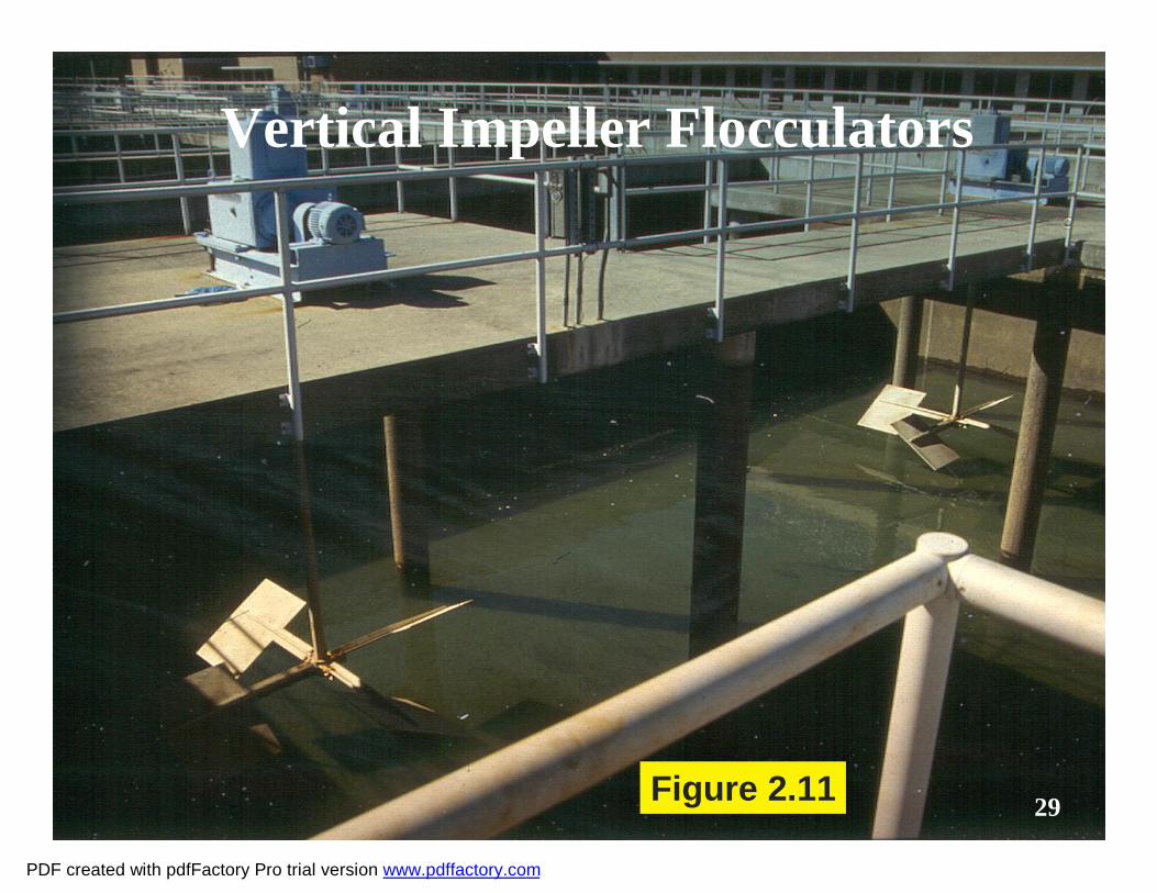
Vertical Impeller Flocculators
29Figure 2.11
PDF created with pdfFactory Pro trial version www.pdffactory.com
30
Vertical Shaft Paddle Flocculator
Figure 2.12
PDF created with pdfFactory Pro trial version www.pdffactory.com
31
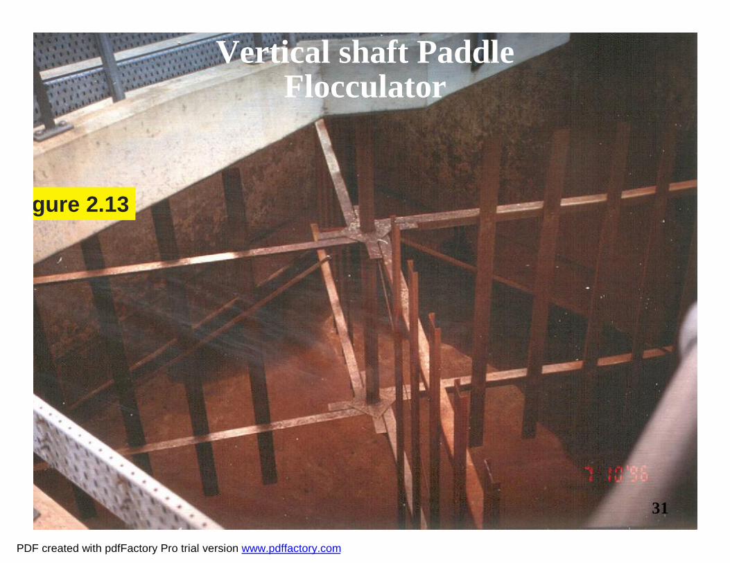
Vertical shaft Paddle Flocculator
31
Figure 2.13
PDF created with pdfFactory Pro trial version www.pdffactory.com

3232
Vertical shaft Paddle Flocculation
tank
Coagulation Rapid Mixer
Sedimentation Tank
Figure 2.14PDF created with pdfFactory Pro trial version www.pdffactory.com

33
Horizontal Paddle Flocculator1. Drive motor2. Variable speed drice3. Gear reducer4. Chain & sprocket power
transfer5. Stuffing box6. Flocculator line shafting7. Shasft connections8. Bearings9. Paddle reel assemblies
Figure 2.15
PDF created with pdfFactory Pro trial version www.pdffactory.com

34
Horizontal Paddle Flocculator
Figure 2.16
PDF created with pdfFactory Pro trial version www.pdffactory.com

35
Walking Beam Flocculator
Figure 2.17
PDF created with pdfFactory Pro trial version www.pdffactory.com

36
Walking Beam Flocculator
36Figure 2.18
PDF created with pdfFactory Pro trial version www.pdffactory.com

37
Walking Beam Flocculator
Figure 2.19
PDF created with pdfFactory Pro trial version www.pdffactory.com

38
Horizontal Baffled Flocculator
Figure 2.20
PDF created with pdfFactory Pro trial version www.pdffactory.com

39
Vertical Baffled Flocculator
Figure 2.21
PDF created with pdfFactory Pro trial version www.pdffactory.com

4040
Figure 2.22
PDF created with pdfFactory Pro trial version www.pdffactory.com

41
Horizontal Flocculators
41Figure 2.23PDF created with pdfFactory Pro trial version www.pdffactory.com

42
Flocculator
42Figure 2.24PDF created with pdfFactory Pro trial version www.pdffactory.com