water quality permits, license, agreement & · pdf filem32 water quality information...
TRANSCRIPT

FOR CONTRACT NO: 04-013524
PROJECT ID: 04-12000608
INFORMATION HANDOUT
WATER QUALITY
WQ1 California Regional Water Quality Control Board Order 01-120 (Issued October 17, 2001)
WQ2 California Regional Water Quality Control Board Order R2-2002-0011
(Issued January 23, 2002)
PERMITS, LICENSE, AGREEMENT & CERTIFICATION
P1 California Department of Fish and Game (CDFG) Incidental Take Permit No. 2081-2001-021-03 (Issued November 19, 2001)
P2 CDFG Incidental Take Permit No. 2081-2001-021-03 Minor Amendment #1
(Issued October 14, 2009)
P3 CDFG Incidental Take Permit No. 2081-2001-021-03 Major Amendment #2 (Issued February 23, 2012)
P4 CDFG Incidental Take Permit No. 2081-2001-021-03 Minor Amendment #3
(Issued September 6, 2012)
P5 U.S. Army Corps of Engineers (ACOE) Permit No. 023013S (Issued December 04, 2001)
P6 U.S Army Corps of Engineers (ACOE) Permit No. 023013S Letter of Modification
(Issued April 2, 2002)
P7 U.S Army Corps of Engineers (ACOE) Permit No. 023013S Letter of Modification (Issued November 12, 2002)
P8 U.S Army Corps of Engineers (ACOE) Permit No. 023013S Letter of Modification
(Issued April 11, 2005)
P9 U.S Army Corps of Engineers (ACOE) Permit No. 023013S Letter of Modification (Issued August 15, 2005)
P10 U.S Army Corps of Engineers (ACOE) Permit No. 023013S Letter of Modification
(Issued September 23, 2005)
P11 U.S. Army Corp of Engineers (ACOE) Permit No. 023013S Letter of Modification (Issued May 20, 2008)
P12 U.S. Army Corp of Engineers (ACOE) Permit No. 023013S Time Extension
(Issued November 16, 2011)
P13 U.S. Army Corp of Engineers (ACOE) Permit No. 023013S Letter of Modification (Issued July 6, 2012)

FOR CONTRACT NO: 04-013524
PROJECT ID: 04-12000608
P14 San Francisco Bay Conservation and Development Commission (BCDC) Permit No. 2001.008.34, Issued November 20, 2001
Last Amended January 23, 2014, Reflects Amendments 1-34
P15 National Marine Fisheries Service (NMFS) Biological Opinion and Incidental Take Statement (Issued October 30, 2001)
P16 NMFS Supplemental Biological Opinion and Conference Opinion
(Issued April 10, 2009)
P17 NMFS Supplemental Biological Opinion and Conference Opinion (Issued August 21, 2009)
P18 NMFS Supplemental Biological Opinion and Conference Opinion
(Issued February 6, 2012)
P19 NMFS Incidental Harassment Authorization (Issued December 18, 2013)
P20 U.S. Fish and Wildlife Service (USFWS) Biological Opinion
(Issued October 29, 2001)
P21 U.S. Coast Guard (USCG) New Bridge Permit 3-01-11 (Issued December 11, 2001)
P22 U.S. Coast Guard (USCG) New Bridge Permit Amendment 3a-01-11
(Issued November 18, 2011)
MATERIALS INFORMATION
M1 SFOBB 504' & 288' Spans Inspection Reports
M2 SFOBB 504' & 288' Spans Original Construction Sequence
M3 SFOBB East Span Design Specifications – Superstructure Circa 1933
M4 Existing Bridge Modification Contract 4011 Resident Engineers Report on Deck Paving –East Bay July 19 1963 (Testing Reports and Contract Specifications)
M5 Existing Bridge Modification Contract 4030 Resident Engineers Report on Steel Work – East Bay
Sept 18 1963 (Testing Reports and Contract Specifications)
M6 Original Bridge Contract 7 Superstructure East Bay Crossing Final Report March 24 1937 (Material Specifications and Testing Reports)
M7 Original Bridge Contract 7 Superstructure East Bay Crossing Specifications March 8 1933 (Contract
Specifications and Cantilever Erection Procedure)
M8 Original Bridge Tests of Heavy Riveted Joints – Second Progress Report (1936)
M9 Original Bridge Tests of Heavy Riveted Joints – Special Report on Manganese Steel Specimens (1936)
M10 Original Bridge Tests on Riveted Tension Members and Their Connections (1934)

FOR CONTRACT NO: 04-013524
PROJECT ID: 04-12000608
M11 SFOBB East Span Floor System Original Design Calculations (1933)
M12 SFOBB East Span Original Construction Photographs from Bancroft Library
M13 Pile Installation Demonstration Project (PIDP) Geotechnical Report: Main Text and Appendices
M14 Ground Motion Report: Main Text and Appendices
M15 Final Marine Geophysical Survey Report:
Volume-1, Main Text and Appendices Volumne-2, Maps
M16 Final Marine Geotechnical Site Characterization Report:
Volume-1, Main Text and Illustrations Volume-2A through Volume-2H
M17 Phase I Subcontractor Reports - Preliminary Geotechnical Site Characterization
Volume-1 through Volume-4
M18 Phase-II Subcontractor Reports - Final Geotechnical Site Characterization Volume-1 through Volume-3
M19 Analysis and Design Procedures for Pile Foundations Supporting Temporary Towers Skyway
Structures: Main Text and Appendices dated March 2001
M20 Revised Final Oakland Shore Approach Geotechnical Site Characterization Report, dated March 2001: Volumes 1, 2A, 2B, 3, and 4
M21 1920 Geology Reports
M22 1930 Boring Logs for Original Bay Bridge
M23 Final Geotechnical Foundation Report for Oakland Shore Approach Structures
M24 Caltrans Bathymetric Survey Report No. 23.00007024 R1 (2103)
M25 San Francisco-Oakland Bay Bridge East Span Underwater Debris Diagram, dated May 2001
M26 SFOBB East Span Survey Information, Control Diagram dated December 30, 2002
M27 USCG Private Aid to Navigation Sample Application Form
M28 Geotechnical & Material Report for YBI
M29 Ground Penetration Report No. 6488-01, GEO Vision, November 2006
M30 Historical Maps (1917, 1932, 1933)
M31 Construction Vibration Monitoring Field Data Form
M32 Water Quality Information Handout (Contract No. 04-01352) dated December 2012
M33 Correspondence with United States Custom Service regarding Jones Act and use of crane/barge,
2002 and 2005

FOR CONTRACT NO: 04-013524
PROJECT ID: 04-12000608
4 REPLACED PER ADDENDUM NO.4 DATED JANUARY 16, 2015
3 ADDED PER ADDENDUM NO.3 DATED DECEMBER 29, 2014
1 ADDED PER ADDENDUM NO.1 DATED OCTOBER 28, 2014
M34 Phase 1 Archaeological Survey Report- Maritime Archaeology, September 1999
M35 Addendum to Archaeological Survey Report-Maritime Archeology, December 6, 1999
M36 Addendum to Archaeological Survey Report-Maritime Archeology, March 2000
M37 Addendum to Archaeological Survey Report-Maritime Archeology, August 17, 2000
M38 SFOBB 504' & 288' Spans Construction Photographs
M39 Addendum Original Bridge Contract 7 Superstructure East Bay Crossing Shop Drawings
M40 Partial BrIM model for the 504' & 288' Spans
M41 Lead concentration data for the roadway asphalt by Advanced Technology Laboratories dated April
30, 2014
M42 Air Dispersion Modeling and Risk Assessment Summary Report for SFOBB 504/288 Spans Demolition
1 M43 Air Dispersion Modeling and Risk Assessment Summary Report for SFOBB Cantilever Truss
Demolition
M44 Air Quality Monitoring Program Summary Report SFOBB Cantilever Truss Demolition (November 2013 through April 2014)
M45 Steel Beam Test-Cut Simulations Air Monitoring Results for SFOBB Oakland Touchdown
Demolition
M46 Bare Steel Risk Assessment – SFOBB Cantilever Truss Demolition Project
M47 Structure Type Selection and Seismic Retrofit Strategy Report (Wharf Condition Report), January 2014
M48 Technical Memorandum - PCB Risk Evalution, Old East Span Deconstruction by AMEC dated
October 17, 2014
M49 Technical Report - 504/288 Contract, Nesting Bird Deterrence Measures dated September 2014 3
M50 Bird Management Plan for Bridge Dismantling - 504/288 Contract dated September 2014
4 M49 Technical Report - 504/288 Contract, Nesting Bird Deterrence Measures dated September 2014

FOR CONTRACT NO.: 04-013524PROJECT ID: 04-12000608
File NameInformation
Handout IndexIndex on SSP
section 2-1.06BDescription
M1 1.1 SFOBB 504' & 288' Spans Inspection ReportsM2 1.2 504' & 288' Spans Original Construction SequenceM3 1.3 SFOBB East Span Design Specifications - Superstructure Circa 1933
M4 1.4Existing Bridge Modification Contract 4011 Resident Engineers Report on Deck Paving - East Bay July 19, 1963 (Testing Reports and Contract Specifications)
M5 1.5Existing Bridge Modification Contract 4030 Resident Engineers Report on Steel Work - East Bay Sept 18, 1963 (Testing Reports and Contract Specifications)
M6 1.6Original Bridge Contract 7 Superstructure East Bay Crossing Final Report March 24, 1937 (Material Specifications and Testing Reports)
M7 1.7Original Bridge Contract 7 Superstructure East Bay Crossing Specifications March 8, 1933 (Contract Specifications and Cantilever Erection Procedure)
M8 1.8 Original Bridge Tests of Heavy Riveted Joints - Second Progress Report (1936)
M9 1.9Original Bridge Tests of Heavy Riveted Joints - Special Report on Manganese Steel Specimens (1936)
M10 1.10 Original Bridge Tests on Riveted Tension Members and Their Connections (1934)M11 1.11 SFOBB East Span Floor System Original Design Calculations (1933)M12 1.12 SFOBB East Span Original Construction Photographs from Bancroft Library
M13 2.1Pile Installation Demonstration Project (PIDP) Geotechnical Report: Main Text and Appendices
M14 2.2 Ground Motion Report: Main Text and Appendices
2.3
2.3
2.42.42.42.42.42 4
INFORMATION HANDOUT
M15
M16
04-013524-IH-Vol01.pdf
04-013524-IH-Vol02.pdf
04-013524-IH-Vol03.pdf
Final Marine Geophysical Survey Report: Volume-1, Main Text and AppendicesVolume-2, MapsFinal Marine Geotechnical Site Characterization Report:Volume-1, Main Text and IllustrationsVolume-2A through Volume-2H
04-013524-IH-Vol04.pdf
Page 1 of 3
2.42.42.42.42.52.52.52.5
04-013524-IH-Vol07.pdf 2.52.62.62.6
M19 2.7Analysis and Design Procedures for Pile Foundations Supporting Temporary Towers Skyway Structures: Main Text and Appendices dated March 2001
2.82.82.82.82.8
M21 2.9 1920 Geology ReportsM22 2.10 1930 Boring Logs for Original Bay BridgeM23 2.11 Final Geotechnical Foundation Report for Oakland Shore Approach StructuresM24 2.12 Caltrans Bathymetric Survey Report No. 23.00007024 R1 (2013)
M17
M18
M20
Phase I Subcontractor Reports - Preliminary Geotechnical Site Characterization Volume-1 through Volume-4
Phase II Subcontractor Reports - Final Geotechnical Site CharacterizationVolume-1 through Volume-3
Revised Final Oakland Shore Approach Geotechnical Site Characterization Report, dated March 2001: Volumes 1, 2A, 2B, 3, and 4
04-013524-IH-Vol06.pdf
04-013524-IH-Vol08.pdf
04-013524-IH-Vol05.pdf
Page 1 of 3
FOR CONTRACT NO.: 04-013524PROJECT ID: 04-12000608
File NameInformation
Handout IndexIndex on SSP
section 2-1.06BDescription
P1 3.1.1California Department of Fish and Game (CDFG) Incidental Take Permit No. 2081-2001-021-03. Issued November 19, 2001
P2 3.1.2CDFG Incidental Take Permit No. 2081-2001-021-03 Minor Amendment #1. Issued October 14, 2009
P3 3.1.3CDFG Incidental Take Permit No. 2081-2001-021-03 Major Amendment #2. Issued February 23, 2012
P4 3.1.4CDFG Incidental Take Permit No. 2081-2001-021-03 Minor Amendment #3. Issued September 6, 2012
P5 3.1.5 U.S. Army Corps of Engineers (ACOE) Permit No. 023013S. Issued December 04, 2001
P6 3.1.6U.S. Army Corps of Engineers (ACOE) Permit No. 023013S Letter of Modification. Issued April 2, 2002
P7 3.1.7U.S. Army Corps of Engineers (ACOE) Permit No. 023013S Letter of Modification. Issued November 12, 2002
P8 3.1.8U.S. Army Corps of Engineers (ACOE) Permit No. 023013S Letter of Modification. Issued April 11, 2005
P9 3.1.9U.S. Army Corps of Engineers (ACOE) Permit No. 023013S Letter of Modification. Issued August 15, 2005
P10 3.1.10U.S. Army Corps of Engineers (ACOE) Permit No. 023013S Letter of Modification. Issued September 23, 2005
P11 3.1.11U.S. Army Corps of Engineers (ACOE) Permit No. 023013S Letter of Modification. Issued May 20, 2008
P12 3.1.12U.S. Army Corps of Engineers (ACOE) Permit No. 023013S Time Extension. Issued November 16, 2011
P13 3.1.13U.S. Army Corps of Engineers (ACOE) Permit No. 023013S Letter of Modification. Issued July 6, 2012
P14 3.1.14San Francisco Bay Conservation and Development Commission (BCDC) Permit No. 2001.008.34. Issued November 20, 2001, Last Amended January 23, 2014, Reflects Amendments 1-34
P15 3.1.15National Marine Fisheries Service (NMFS) Biological Opinion and Incidental Take Statement. Issued October 30, 2001
P16 3.1.16 NMFS Supplemental Biological Opinion and Conference Opinion. Issued April 10, 2009P17 3.1.17 NMFS Supplemental Biological Opinion and Conference Opinion. Issued August 21, 2009P18 3.1.18 NMFS Supplemental Biological Opinion and Conference Opinion. Issued February 6, 2012P19 3.1.19 NMFS Incidental Harassment Authorization. Issued December 18, 2013
04-013524-IH-Vol09.pdf
Page 2 of 3
P19 3.1.19 NMFS Incidental Harassment Authorization. Issued December 18, 2013P20 3.1.20 U.S. Fish and Wildlife Service (USFWS) Biological Opinion. Issued October 29, 2001P21 3.1.21 U.S. Coast Guard (USCG) New Bridge Permit 3-01-11. Issued December 11, 2001
P22 3.1.22U.S. Coast Guard (USCG) New Bridge Permit Amendment 3a-01-11. Issued November 18, 2011
WQ1 3.1.23 California Regional Water Quality Control Board Order 01-120. Issued October 17, 2001
WQ2 3.1.24California Regional Water Quality Control Board Order R2-2002-0011. Issued January 23, 2002
M25 3.2San Francisco-Oakland Bay Bridge East Span Underwater Debris Diagram, dated May 2001
M26 3.3 SFOBB East Span Survey Information, Control Diagram Dated December 30, 2002M27 3.4 USCG Private Aid to Navigation Sample Application Form
3.53.5
M29 3.6 Ground Penetration Report No. 6488-01, GEO Vision, November 2006M30 3.7 Historical Maps (1917, 1932, 1933)M31 3.8 Construction Vibration Monitoring Field Data FormM32 3.9 Water Quality Information Handount (Contract No. 04-01352) dated December 2012
M33 3.10Correspondence with United States Custom Service regarding Jones Act and use of crane/barge, 2002 and 2005
M34 3.11.1 Phase 1 Archaeological Survey Report-Maritime Archaeology, September 1999M35 3.11.2 Addendum to Archaeological Survey Report-Maritime Archeology, December 6, 1999M36 3.11.3 Addendum Archaeological Survey Report-Maritime Archaeology, March 2000M37 3.11.4 Addendum to Archaeological Survey Report-Maritime Archeology, August 17, 2000
Geotechnical & Material Report for YBIM28
Page 2 of 3

FOR CONTRACT NO.: 04-013524PROJECT ID: 04-12000608
M38 1.13 SFOBB 504' & 288' Spans Construction PhotographsM39 1.14 Original Bridge Contract 7 Superstructure East Bay Crossing Shop DrawingsM40 1.15 Partial BrIM model for the 504' & 288' Spans
M41 3.13Lead concentration data for the roadway asphalt by Advanced Technology Laboratories dated April 30, 2014
M42 3.14Air Dispersion Modeling and Risk Assessment Summary Report for SFOBB 504/288 Spans Demolition
M43 3.15Air Dispersion Modeling and Risk Assessment Summary Report for SFOBB Cantilever Truss Demolition
M44 3.16Air Quality Monitoring Program Summary Report SFOBB Cantilever Truss Demolition (November 2013 through April 2014)
M45 3.17Steel Beam Test-Cut Simulations Air Monitoring Results for SFOBB Oakland Touchdown Demolition
M46 3.18 Bare Steel Risk Assessment – SFOBB Cantilever Truss Demolition Project
M47 3.19Structure Type Selection and Seismic Retrofit Strategy Report (Wharf Condition Report), January 2014
M48 3.20Technical Memorandum - PCB Risk Evalution, Old East Span Deconstruction by AMEC dated October 17, 2014
M49 3.21Technical Report - 504/288 Contract, Nesting Bird Deterrence Measures dated September 2014
M50 3.22 Bird Management Plan for Bridge Dismantling - 504/288 Contract dated September 2014
04-013524ad3-IH.pdf
3
04-013524ad4-IH.pdf
4M49 3.21
Technical Report - 504/288 Contract, Nesting Bird Deterrence Measures dated September 2014
04-013524ad1-IH.pdf
Page 3 of 3
3 ADDED PER ADDENDUM NO. 3 DATED DECEMBER 29, 2014
1 ADDED PER ADDENDUM NO. 1 DATED OCTOBER 28, 2014
4 REPLACED PER ADDENDUM NO. 4 DATED JANUARY 16, 2015
Page 3 of 3
San Francisco – Oakland Bay Bridge
East Span Seismic Safety Project
September 2014
EA 04-01352104-SF-80 KP 12.2/KP 14.304-ALA-80 KP 0.0/KP 2.1
TECHNICAL REPORT
504/288 ContractNESTING BIRD DETERRENCE MEASURES:MATERIALS AND APPLICATIONS
4 REPLACED PER ADDENDUM NO. 4 DATED JANUARY 16, 2015
������������������������ ��������������������������
For individuals with sensory disabilities, this document is available in Braille, large print, on audiocassette, or computer disk. To obtain a copy in one of these alternate formats, please call or write to Caltrans, Attn: Stefan Galvez-Abadia, District Office Chief, Environmental Analysis, 111 Grand Avenue, Oakland, CA 94612; (510)-867-6785 Voice, or use the California Relay Service TTY number (800)-735-2929.

San Francisco-Oakland Bay Bridge East Span Seismic Safety Project
504/288 Nesting Bird Deterrence
Materials and Applications
EA 04-013521
September 2014
STATE OF CALIFORNIADepartment of Transportation
Prepared By: ___________________________________ Date: _1/08/2015__
Eric Jepsen, Wildlife EcologistGarcia and Associates
Reviewed By: ___________________________________ Date: _1/08/2015__
Dillon Lennebacker, Ecologist/Permitting SpecialistGarcia and Associates
Approved By: ___________________________________ Date: _1/108/2015_
Stefan Galvez-Abadia, District Office ChiefOffice of Environmental AnalysisDistrict 4, California Department of Transportation(510) 867-6785

ii
Table of Contents
CHAPTER 1 – INTRODUCTION 1
1.1 Project Description 1
1.2 SFOBB and the Dismantling of the 504-ft and 288-ft Spans of the Original East Span 2
CHAPTER 2 – STRUCTURAL MEMBER GROUPS AND CHARACTERISTICS 3
2.1 Overview 3
2.2 Structural Member Groups 3
Marine Foundations 3
Steel Support Towers 6
Below Lower Deck Structural Members 8
Upper Superstructure 11
Existing Access Platforms 12
Concrete Oakland Shore Structure 14
Temporary Supports 14
Chapter 3 – BIRD MANAGEMENT 15
3.1 Phase 1: Non-Nesting Season (September 1-January 31) 15
Seasonal Avoidance 15
Historic Nest Removal 15
Deterrence Measures 15
3.2 Phase 2: Nesting Season (February 1-August 31) 16
Nest-Start Removal 16
Paint Ball Gun and Water Cannon (for nest-start removal only) 17
Supplemental Exclusionary Deterrence Measures 17
Hazing17
Buffers (for occupied nests) 17
Occupied Nest Removal 18

iii
CHAPTER 4 – CONTRACTOR DETERRENCE PLAN 19
4.1 Seasonal Avoidance 19
4.2 Deterrents 19
4.3 Occupied Nest Removal 21
4.4 Buffers for Occupied Nests 21
4.5 Deterrent Location, Means, and Methods for Installation 21
CHAPTER 5 - DETERRENT MATERIALS SPECIFICTIONS 22
5.1 Deterrent Materials 22
Bird Spikes 22
Slope Panels: 24
Netting: 25
Suspended Scaffolding System: 26
Welded Hardware Cloth: 27
Bird-Wire System: 28
List of Figures
Figure 1.1 SFOBB project and vicinity .........................................................................................1
Figure 1.2 SFOBB new and original east spans.............................................................................1
Figure 2.1 Marine foundation at Pier E7 with raised pedestals, ledge areas around pedestals, and large open area between pedestals. ..................................................................................................4
Figure 2.2 Wooden fender at Pier E5..............................................................................................4
Figure 2.3 Pier E9 pedestal top and weep holes. ............................................................................5
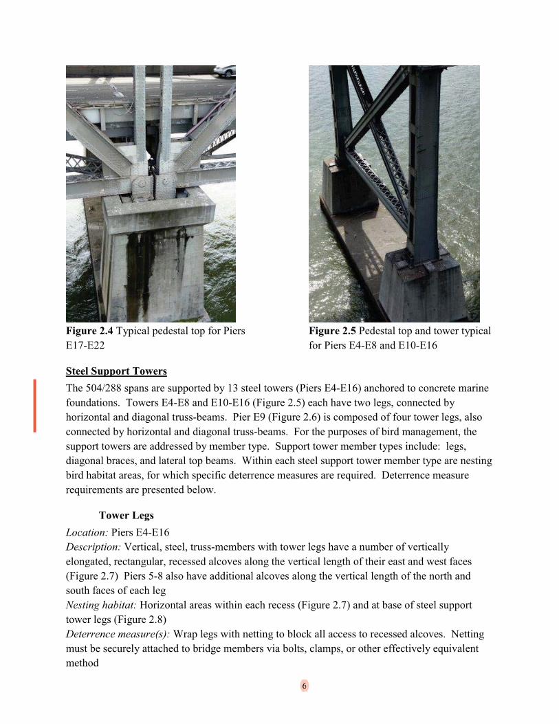
Figure 2.4 Typical pedestal top for Piers E17-E22.........................................................................6
Figure 2.5 Pedestal top and tower typical for Piers E4-E8 and E10-E16 .......................................6
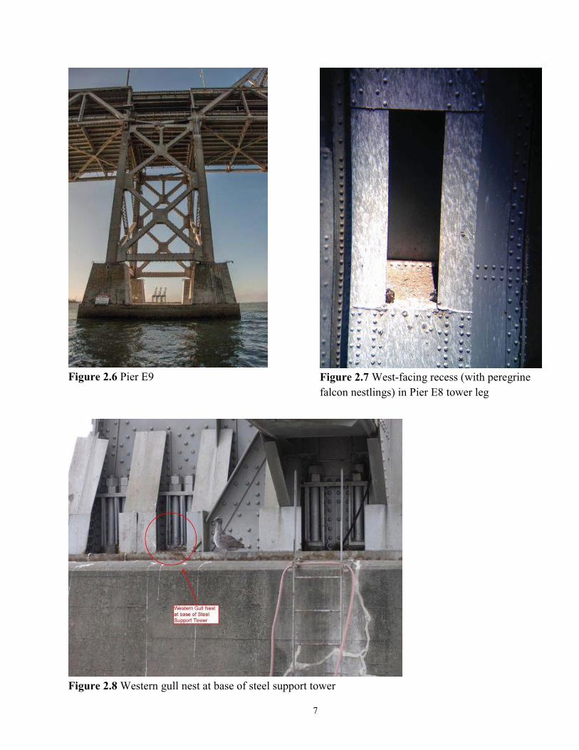
Figure 2.6 Pier E9 ...........................................................................................................................7

iv
Figure 2.7 West-facing recess (with peregrine falcon nestlings) in Pier E8 tower leg...................7
Figure 2.8 Western gull nest at base of steel support tower ...........................................................7
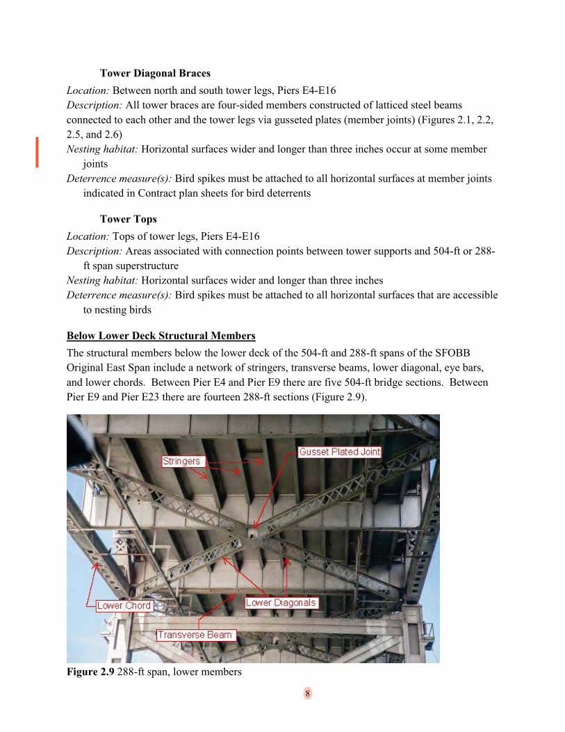
Figure 2.9 288-ft span, lower members ..........................................................................................8
Figure 2.10 Double-crested cormorant nest on eye-bars ..............................................................11
Figure 2.11 Typical superstructure for 504-ft span.......................................................................11
Figure 2.12 Pier E16 existing access platforms on tower leg .......................................................13
Figure 2.13 Pier E22 existing access platforms typical on 288-ft spans.......................................13
Appendices
Appendix A - SFOBB Original East Span Piers
Appendix B – 504-ft Span Superstructure Cross Section
Appendix C – Existing Access Platforms, General Locations

v
ACRONYMS AND ABBREVIATED TERMS
2014 BMP San Francisco-Oakland Bay Bridge East Span Seismic Safety Project Bird Management Plan for Bridge Dismantling - 504/288 Contract (Supplement to the 2003 Final (Revised) Bird Monitoring and Management Plan)
504/288 The 504-foot Truss Spans and 288-foot Truss Spans of the original east span of the SFOBB
BCDC San Francisco Bay Conservation and Development Commission
BDP Bird Deterrence Plan
CDFW California Department of Fish and Wildlife (formally: California Department of Fish and Game)
CFGC California Fish and Game Code
CESA California Endangered Species Act
Department California Department of Transportation
FEIS San Francisco-Oakland Bay Bridge East Span Seismic Safety Project Final Environmental Impact Statement
FESA Federal Endangered Species Act
MBTA Migratory Bird Treaty Act
OTD Oakland Touchdown
PLAC Permits Licenses Agreements and Certifications
RWQCB Regional Water Quality Control Board
SFOBB San Francisco-Oakland Bay Bridge
SFOBB Project San Francisco-Oakland Bay Bridge East Span Seismic Safety Project
USFWS United States Fish and Wildlife Service

1
CHAPTER 1 – INTRODUCTION
1.1 Project Description
The California Department of Transportation (Department) has replaced the east span of the San Francisco-Oakland Bay Bridge (SFOBB) with a new bridge immediately to the north of the original span. The SFOBB East Span Seismic Safety Project (SFOBB Project) site is located in the central San Francisco Bay, between Yerba Buena Island in the City and County of San Francisco, and the City of Oakland, in Alameda County, in California (Figure 1.1). The SFOBB Project includes both the construction of the new east span and the dismantling of the original east span (Figure 1.2 and Appendix A). The SFOBB Project is a multi-year effort that involves a number of construction activities on land as well as in San Francisco Bay. Some of these activities could potentially affect protected bird species.
Figure 1.1 SFOBB project and vicinity
Figure 1.2 SFOBB new and original east spans

2
To address potential impacts to environmental resources, the Department and Federal Highway Administration prepared the SFOBB Project Final Environmental Impact Statement (FEIS), dated May 2001, pursuant to the National Environmental Policy Act. The Department alsoobtained approvals from regulatory agencies for all activities associated with both the construction of the new east span and the dismantling of the original east span. Regulatory agency approvals obtained from the United States Fish and Wildlife Service (USFWS), the California Department of Fish and Wildlife (CDFW), formerly the California Department of Fish and Game (CDFG), and the San Francisco Bay Conservation and Development Commission (BCDC) specifically addressed potential impacts to birds. When the FEIS was prepared and agency approvals were obtained in 2001, three federally and/or state listed bird species were identified as being present in or near the project area. These species are the California least tern, California brown pelican, and American peregrine falcon. The California least tern is also listed as endangered under both the Federal Endangered Species Act (FESA) and the California Endangered Species Act (CESA). The formerly state and federally endangered California brown pelican was delisted from both FESA and CESA in 2009. The formerly state and federally endangered American peregrine falcon was delisted from FESA in 1999 and delisted from CESA in 2008. The California least tern, California brown pelican, and American peregrine falcon, remain fully protected by the California Fish and Game Code (CFGC).
In addition to birds identified in SFOBB Project approvals, the Department also observes other applicable state and federal regulations, such as the federal Migratory Bird Treaty Act (MBTA) and the CFGC, to protect birds and their nests within the SFOBB Project area.
1.2 SFOBB and the Dismantling of the 504-ft and 288-ft Spans of the Original East Span
The purpose of this report is to identify bird deterrence requirements for the SFOBB Project Construction Contract to remove the 504-foot and 288-foot spans (504/288) and steel support towers of the Original East Span beginning during the 2015 nesting season. The Department expects the 504/288 contractor to submit a work sequence for dismantling the SFOBB Original East Span from commencement of work and continuing through the duration of the contract. Based on this work sequence, the risk of impacts to nesting birds over multiple nesting seasons can be assessed. Impacts may result from the numerous construction activities, including construction of temporary marine falsework, dismantling of the original east span superstructureeast of Pier E4 (see Appendix A for all pier locations), and dismantling of the pier towers.
In this report, we identify structural member groups, their characteristics with regards to nesting birds, and bird deterrence measures to potentially mitigate risk to schedule that may occur if bird nesting results in work stoppages during dismantling activities. This report provides a detailed summary of recommended deterrence measures, deterrence measure installation methods, maintenance, access, staging and scheduling requirements, as well as recommendations for the contractor-supplied Bird Deterrence Plan (BDP).

3
CHAPTER 2 – STRUCTURAL MEMBER GROUPS AND CHARACTERISTICS
2.1 OverviewThe 504/288 spans are composed of multiple structural member groups all of which provide some historic or potential nesting bird habitat. Each member group is best suited to specific deterrence measure applications. These structural member groups are: marine foundations,support towers, below lower deck structure, lower deck, upper deck, superstructure, concrete Oakland shore structure, access platforms and temporary supports. In many areas unique location-specific deterrence measures are required. Deterrents discussed in this report are described by material specifications presented in Chapter 5 and shall be installed as shown in 504/288 Contract Specifications. Unique, and general, member-defined requirements are presented in this chapter. In many cases, deterrence measures implemented for one member group must overlap with those of adjacent member groups to create a seamless deterrence system covering both groups. Deterrence measures are to be monitored and maintained daily for effectiveness by the contractor supplied biologist(s).
2.2 Structural Member Groups
Marine FoundationsThe 504/288 spans are constructed on 20 marine foundations (Piers E4-E22) of concrete construction and consisting of multiple horizontal and vertical planes. The marine foundations provide access points to bridge support towers as well as suitable nesting habitat for birds. These habitat areas include: horizontal concrete surfaces (Piers E4-E22), wooden fenders (Piers E4-E5), corner areas defined by vertical and horizontal surfaces at the bases of concrete pedestals(Piers E4-E22), weep holes (Piers E9, E17-E22), and concrete pedestal tops (Piers E9, E17-E22).
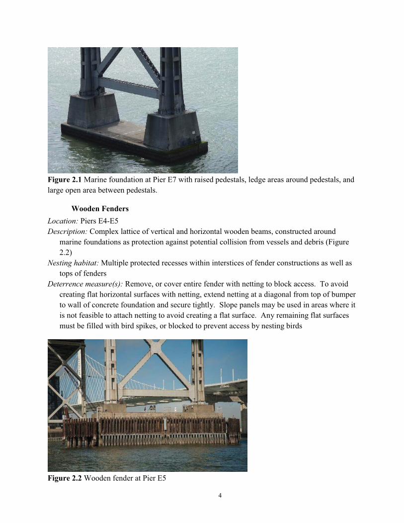
Horizontal Concrete SurfacesLocation: Piers E4-E22Description: Flat, open areas between concrete pedestals defined by tops of concrete foundations
(Figure 2.1).Nesting habitat: Anywhere on surfaceDeterrence measure(s): Large, flat surfaces are not feasibly covered by exclusionary deterrence
measures and may need to be left open for access to construction area. These areas shall be managed by contractor biologist(s) to prevent or remove nest starts. Management strategies for these areas may include, but are not limited to monitoring, bird-hazing, and removal of nest starts
4
Figure 2.1 Marine foundation at Pier E7 with raised pedestals, ledge areas around pedestals, and large open area between pedestals.
Wooden FendersLocation: Piers E4-E5Description: Complex lattice of vertical and horizontal wooden beams, constructed around
marine foundations as protection against potential collision from vessels and debris (Figure 2.2)
Nesting habitat: Multiple protected recesses within interstices of fender constructions as well as tops of fenders
Deterrence measure(s): Remove, or cover entire fender with netting to block access. To avoid creating flat horizontal surfaces with netting, extend netting at a diagonal from top of bumper to wall of concrete foundation and secure tightly. Slope panels may be used in areas where it is not feasible to attach netting to avoid creating a flat surface. Any remaining flat surfaces must be filled with bird spikes, or blocked to prevent access by nesting birds
Figure 2.2 Wooden fender at Pier E5

5
Concrete Pedestal BasesLocation: Piers E4-E22Description: Intersections between the base of semi-vertical concrete pedestal sides with the
horizontal concrete surface on marine foundations (Figures 2.1-2.5)Nesting habitat: Semi-protected, corner areas defined by vertical and horizontal slab surfacesDeterrence measure(s): Fill corner areas with slope panels, and welded hardware cloth
Weep HolesLocation: Concrete pedestals at Piers E9, E17-E22Description: Narrow openings through concrete pedestals to allow water to pass from depressed
pedestal tops (Figure 2.3)Nesting habitat: Cavity created by weep holeDeterrence measure(s): Survey weep holes for presence of birds and/or active nests prior to
blocking. If weep hole is uninhabited, cover with welded hardware cloth.
Concrete Pedestal TopsLocation: Tops of concrete pedestals at Piers E9 and E17-E22Description: Recessed areas on concrete pedestals tops and associated connection points with
support towers (Pier E9, Figure 2.3) or superstructure support beams (Piers E17-E22, Figure 2.4), as well as flat pedestal tops ((Piers E4-8 and E10-E16, Figure 2.5)
Nesting habitat: Horizontal surfaces and corners within recessed areasDeterrence measure(s): Cover entire area with netting to block access. Fill difficult-to-cover
areas with supplemental bird spikes, or slope panels to prevent bird access. The contractor-supplied biologist is required to flush out potential nesting birds as part of monitoring duties
Figure 2.3 Pier E9 pedestal top and weep holes.
6
Figure 2.4 Typical pedestal top for Piers E17-E22
Figure 2.5 Pedestal top and tower typical for Piers E4-E8 and E10-E16
Steel Support TowersThe 504/288 spans are supported by 13 steel towers (Piers E4-E16) anchored to concrete marine foundations. Towers E4-E8 and E10-E16 (Figure 2.5) each have two legs, connected by horizontal and diagonal truss-beams. Pier E9 (Figure 2.6) is composed of four tower legs, also connected by horizontal and diagonal truss-beams. For the purposes of bird management, the support towers are addressed by member type. Support tower member types include: legs, diagonal braces, and lateral top beams. Within each steel support tower member type are nesting bird habitat areas, for which specific deterrence measures are required. Deterrence measure requirements are presented below.
Tower LegsLocation: Piers E4-E16Description: Vertical, steel, truss-members with tower legs have a number of vertically elongated, rectangular, recessed alcoves along the vertical length of their east and west faces(Figure 2.7) Piers 5-8 also have additional alcoves along the vertical length of the north and south faces of each legNesting habitat: Horizontal areas within each recess (Figure 2.7) and at base of steel support tower legs (Figure 2.8)Deterrence measure(s): Wrap legs with netting to block all access to recessed alcoves. Netting must be securely attached to bridge members via bolts, clamps, or other effectively equivalentmethod
6
7
Figure 2.6 Pier E9 Figure 2.7 West-facing recess (with peregrine falcon nestlings) in Pier E8 tower leg
Figure 2.8 Western gull nest at base of steel support tower
8
Tower Diagonal BracesLocation: Between north and south tower legs, Piers E4-E16Description: All tower braces are four-sided members constructed of latticed steel beams connected to each other and the tower legs via gusseted plates (member joints) (Figures 2.1, 2.2,2.5, and 2.6)Nesting habitat: Horizontal surfaces wider and longer than three inches occur at some member
jointsDeterrence measure(s): Bird spikes must be attached to all horizontal surfaces at member joints
indicated in Contract plan sheets for bird deterrents
Tower TopsLocation: Tops of tower legs, Piers E4-E16Description: Areas associated with connection points between tower supports and 504-ft or 288-
ft span superstructureNesting habitat: Horizontal surfaces wider and longer than three inchesDeterrence measure(s): Bird spikes must be attached to all horizontal surfaces that are accessible
to nesting birds
Below Lower Deck Structural MembersThe structural members below the lower deck of the 504-ft and 288-ft spans of the SFOBB Original East Span include a network of stringers, transverse beams, lower diagonal, eye bars, and lower chords. Between Pier E4 and Pier E9 there are five 504-ft bridge sections. Between Pier E9 and Pier E23 there are fourteen 288-ft sections (Figure 2.9).
Figure 2.9 288-ft span, lower members
8
9
The joints among transverse beams and lower diagonals provide the most extensive nesting bird habitat on the bridge as well as the least accessible areas for deterrence measure installation. The transverse beams of both sections are composed of solid web I-beams with narrow ledges that are not suitable for nesting. The lower diagonals are laterally mounted, lattice web I-beams wide enough to provide suitable nesting habitat both along the top lengths and lower ledge surfaces of each member.
Historic nesting activity has left guano built up along the bottom superstructure members including the transverse beams, lower diagonals, and at joints connecting members.
A double-crested cormorant colony is located primarily within the lower members of the bridge,therefore nesting bird deterrence measures for the bottom of the bridge will require completeexclusion. Use of a suspended scaffolding system netted at all open ends and scaffolding deck openings will provide bird exclusion from these areas. If a scaffolding system fails to provide exclusion, wrap all diagonals with netting, clean and spike all flat surfaces at joints and install bird-wire system on top surfaces of all lateral members that are accessible to birds. The suspended scaffolding system will also provide nesting bird monitoring and deterrence monitoring access to the below-deck structural members.
Transverse Beams (Floor Beams)Location: 504 and 288-ft spans; Large I-beams beneath road deck stringers mounted
perpendicular to roadwayDescription: Steel plated beams (Figure 2.9)Nesting habitat: No significant nesting habitat, except at joints with lower diagonalsDeterrence measure(s): Block access to underside of bridge with a suspended scaffolding system
enclosed with netting, or equivalent deterrence measures
Lower DiagonalsLocation: 504-ft spans: integrated within level of below lower deck transverse beams; 288-ft
spans: beneath below lower deck transverse beamsDescription: Steel I-beams with lattice web mounted below the lower deck laterally and diagonal
to roadway (Figure 2.9)Nesting habitat: Tops of members, lower ledges and within lattice; these members present the
largest area of historic nesting by the double-crested cormorant colonyDeterrence measure(s): Block access to underside of bridge with a suspended scaffolding system
and netting, except at working ends for immediate removal. Any spans with the bridge bottom exposed, wrap horizontal members individually with netting. Install bird spikes on tops of wrapped members, fill member joints with bird spikes, or block with welded wire hardware cloth
Joints/Gusseted platesLocation: 504-ft and 288-ft spans; connection points among lateral and/or vertical members
10
Description: Steel plates connecting bridge members and associated areas (Figure 2.9)Nesting habitat: Horizontal surfaces with a length and width of three inches or moreDeterrence measure(s): Block access to underside of bridge with a suspended scaffolding system
and netting. In areas not excluded by the suspended scaffolding system install spikes within lateral surfaces ofall plated member joints as directed by the Contract plan sheets for birddeterrents
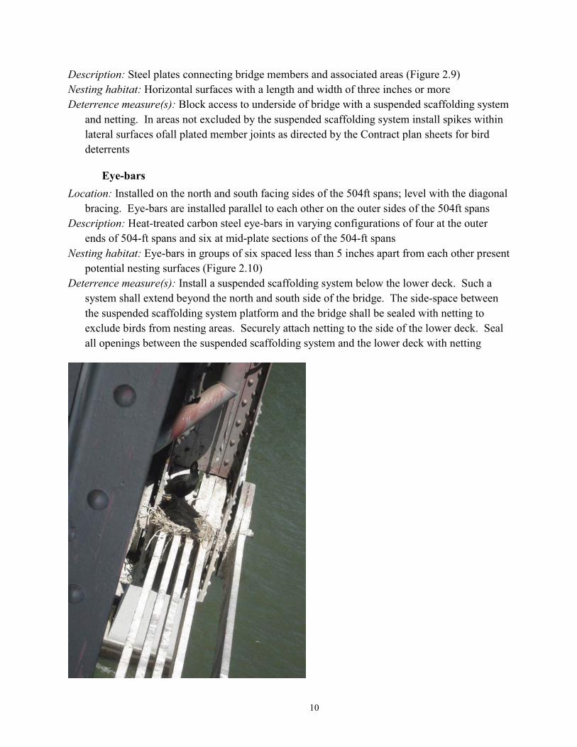
Eye-barsLocation: Installed on the north and south facing sides of the 504ft spans; level with the diagonal
bracing. Eye-bars are installed parallel to each other on the outer sides of the 504ft spansDescription: Heat-treated carbon steel eye-bars in varying configurations of four at the outer
ends of 504-ft spans and six at mid-plate sections of the 504-ft spansNesting habitat: Eye-bars in groups of six spaced less than 5 inches apart from each other present
potential nesting surfaces (Figure 2.10)Deterrence measure(s): Install a suspended scaffolding system below the lower deck. Such a
system shall extend beyond the north and south side of the bridge. The side-space between the suspended scaffolding system platform and the bridge shall be sealed with netting to exclude birds from nesting areas. Securely attach netting to the side of the lower deck. Seal all openings between the suspended scaffolding system and the lower deck with netting

11
Figure 2.10 Double-crested cormorant nest on eye-bars
Lower ChordsLocation: North and south sides of the 288-ft spansDescription: Four-sided members constructed of steel plates and lattice, running parallel with the
roadway and level with the lower diagonals (Figure 2.9)Nesting habitat: Horizontal steel plates wider and longer than three inches at ends of lower
chords provide suitable habitat. Lower chord lattice areas do not provide suitable nesting habitat
Deterrence measure(s): Install a suspended scaffolding system below the lower deck. Such a system shall extend beyond the north and south side of the bridge. The side-space between the suspended scaffolding system platform and the bridge shall be sealed with netting to exclude birds from nesting areas. Securely attach netting to the side of the lower deck. Seal all openings between the suspended scaffolding system and the lower deck with netting
Upper SuperstructureFor this technical report, the upper superstructure refers to the bridge members extending above the bottom lateral structures, including the lower deck, the upper deck, and upper laterals (Figure 2.11, Appendix B). Most locations in these structures will be highly accessible during the dismantling process. Based on this accessibility as well as low incidence of historical nesting locations in upper superstructure locations, deterrence measure requirements for these areas emphasize daily monitoring, hazing, nest-start removal, supplemental deterrents and installation of deterrents as shown in Contract plans.
Figure 2.11 Typical superstructure for 504-ft span

12
Lower DeckLocation: 504-ft and 288-ft spans; lower roadway and associated bridge membersDescription: Stringers, road surface, shoulder walkways, railings and truss membersNesting habitat: Horizontal surfaces greater than 3 inches by 3 inches provide potential nesting
area. Probability of nesting in these locations is low, as this area will be at the center of an active construction zone
Deterrence measure(s): Implement daily monitoring, hazing, nest-start removal, and installation of supplemental deterrents
Upper DeckLocation: 504/288 spans; above lower deckDescription: Floor beams, crossbeams, stringers, road surface, shoulder walkways, railingsNesting habitat: Horizontal surfaces greater than 3 inches by 3 inchesHorizontal surfaces greater than 3in by 3in provide potential nesting area. Probability of nesting
in these locations is low, as this area will be at the center of an active construction zoneDeterrence measure(s): The upper deck road surface, walkways and railings may be removed
early in the dismantling Contract, thereby eliminating most of the upper deck nesting surfaces. If they are not removed prior to the onset of the bird nesting season, proceed with installation of deterrence measures as shown in plan sheets. Probability of nesting in this area is low. In areas where potential nest sites remain, implement daily monitoring, hazing, nest-start removal, and installation of supplemental deterrents
Upper LateralsLocation: 504-ft spans; steel superstructure surrounding upper deckDescription: Steel truss members, beams and connecting jointsNesting habitat: Horizontal surfaces greater than 3 inches by 3 inches provide potential nesting
area. Areas include, but not limited to, horizontal surfaces in joints, recesses within hollow members, and along the tops of truss members
Deterrence measure(s): Install bird spikes in joint locations shown on bird deterrent plan sheets.Cover access holes to members with suitable recesses. Access holes to recesses may be covered by wrapping the entire member with netting secured by clamp or equivalent means. Implement daily monitoring, hazing, nest-start removal, and installation of supplemental exclusions
Existing Access PlatformsWithin the attached support tower legs and parts of the superstructure there are a total of 78 existing maintenance platforms on both the north and south side of the bridge. These existing maintenance platforms are associated with electrical boxes, access ladders, or other structures on the bridge requiring regular access (Figure 2.12, 2.13). Platforms occur at general locations shown in Appendix C.Location: North and south side of the superstructure; tower legs.

13
Description: Horizontal platforms, with approximately 4-foot railing.Nesting habitat: Platform surfaceDeterrence measure(s): Platforms that are not critical in accessing other parts of the bridge
structure should be removed prior to the nesting season. If removal of platforms prior to the bird nesting season is not feasible, platforms must be made inaccessible to birds by installing bird spikes, slope paneling, or netting. On remaining access platforms, during the nesting season, implement daily monitoring, hazing, nest-start removal, and installation of supplemental deterrents.
Figure 2.12 Pier E16 existing access platforms on tower leg
Figure 2.13 Pier E22 existing access platforms typical on 288-ft spans
13

14
Concrete Oakland Shore StructureAdditional SFOBB Original East Span land-based foundations occur east of Pier E22, on which the Oakland Touchdown (OTD) is built. Within this structure are multiple protected overhangs located on several concrete bents (Pier E23, Bents E24-E28). Protected overhangs provide nesting habitat for some bird species (Figure 2.14). Deterrence measures are given below.
Protected OverhangsLocation: Pier E23, Bents E24-E28 (OTD)Description: Concrete foundations and road structureNesting habitat: Junction of vertical and horizontal surfaces, which create protected overhangsDeterrence measure(s): During the nesting season, implement daily monitoring, hazing, nest-
start removal, and installation of supplemental deterrents.
Figure 2.14 Black phoebe nest on OTD concrete bent
Temporary SupportsTemporary support structures may be required during the dismantling of the 504/288 spans.These temporary supports will be built and maintained by the contractor. It is the contractor’s responsibility to demonstrate that temporary supports within the Project are in compliance with all environmental and safety laws and Project permits. Any nesting habitat created by temporary supports will be the responsibility of the contractor. Deterrence measure implementation and maintenance will also be the responsibility of the contractor, and must be in accordance with the Department’s 2014 Bird Management Plan (2014 BMP) and reflected in the contractorbiologists’ Bird Protection Plan and Bird Deterrence Plan. All deterrence measures for temporary supports shall comply with all environmental laws and Permits Licenses Agreementsand Certifications (PLACs) issued to the SFOBB Project. The Department will not be responsible for work stoppage as a result of failure to install or maintain deterrence measures on temporary supports.
14

15
CHAPTER 3 – BIRD MANAGEMENT
Bird management within the SFOBB Project area will rely on two phases of management. Phase 1 management focuses on activities during the non-nesting season (September 1 through January 31). This includes performing construction activities during the non-nesting season to avoid nesting birds and proactive prevention of nesting birds for the next nesting season, through the removal of nesting habitat and installation of deterrence measures. By preventing birds from nesting within the SFOBB Project area, the Department and contractor will avoid, and minimize,impacts to nesting birds. Bird-associated delays to the construction progress within the SFOBB Project area will be minimized as well. Phase 2 management will take place during the nesting season (February 1-August 31). Phase 2 strategies include ongoing monitoring of nesting bird activity, removal of nest starts before eggs may be laid, installation of supplemental deterrence measures, hazing, implementation of buffers around occupied nests, and (in specific cases to be determined by the 504/288 Contract RE and Department biologist(s)) occupied nest removal.
3.1 Phase 1: Non-Nesting Season (September 1-January 31)
Seasonal AvoidanceActive demolition may be performed outside of the nesting season without the constraints of nesting bird deterrence measures. Impacts to nesting birds may be avoided by maximizing scheduled construction activities during the non-nesting season. Note: some birds may establish a nest during the non-nesting season (September 1-January 31). Occupied bird nests occurring during the non-nesting season are protected under the MBTA and CFGC. The contractor is responsible for protecting nesting birds within the 504/288 Project area, regardless of the season.
Historic Nest RemovalMany bird species re-use or build on top of old nests remaining from the previous years. Removal of unoccupied old nests from within the SFOBB Project area may act as a deterrence measure to nesting birds. Nests will be physically removed by hand or with small handheld tools. All nests will need to be placed in containment. Nesting material is not permitted to fall into the bay. Access must be provided to nest removal personnel. California Occupational Safety and Health Administration approved respirators and other applicable personal protective equipment must be worn by the nest removal personnel.
Deterrence MeasuresThe following section presents the deterrence measures to be installed on the SFOBB Original East Span. These deterrence measures include bird spikes, bird-slope panels, netting, bird-wire, welded hardware cloth and suspended scaffolding system. The areas of application for deterrence measures correspond with, but are not limited to, the structural member groups presented above and the engineering plans in Appendix I (Appendix I).
15

16
The majority of deterrence measure installation is to be performed during the non-nesting season. Prior to installation of deterrence measures directly onto bridge members, those members must be cleaned. As with removal of historic nesting materials, guano and other materials cleaned from members is not permitted to fall into the bay. The contractor is responsible for removal and containment of waste materials from the construction site. If water is used in the cleaning of members, the contractor is responsible for containment and removal of effluent and debris resulting from this process. Any discharge of water into the Bay must be done in accordance with and permitted by the Regional Water Quality Control Board (RWQCB). The contractor is responsible for seeking approval before pursuing use of any device or methods that will discharge water into the Bay.
The contractor is responsible for all deterrence measure installation, maintenance, replacement, as well as access to nesting sites, staging and scheduling requirements. Project areas scheduled for removal during a nesting season must have a minimum of 1,560 ft. of contiguous suspended scaffolding system and all other deterrence measures installed prior to the start of upcoming nesting seasons. For example, if the contractor plans to remove trusses between February 1 and August 31, deterrence measures must be implemented along at minimum 1,560 ft. of expected removal work area, and must be applied to the entire scheduled work area that is to be active during the upcoming nesting season by January 31. The contractor is responsible for providingthe Department schedule information prior to construction activities in a timely manner to ensure accurate planning of bird deterrence implementation. The contractor is responsible for maintaining a work schedule appropriate to bird nesting season limitations and informing theDepartment in a timely manner of changes to the work schedule. The contractor will provide the Department with plan sheets clearly showing specific locations and types of deterrence measuresto be installed, as well as photos documenting bird deterrence measures.
3.2 Phase 2: Nesting Season (February 1-August 31)
Nest-Start RemovalNest start removal can be an effective measure to deter nesting. Occupied nests are nests that contain birds or eggs and are protected by the MBTA. Removal of occupied nests by the contractor is not permitted.
Birds may initiate nesting at any time during the nesting season. Nest-building may take between one day and several weeks to complete. During this period, nest removal is an effective nesting deterrent. Nest starts without contents must be removed as soon as they are discovered,throughout the nesting season. A nest becomes occupied the moment an egg is laid in it. A nest remains occupied until the young have fledged. The contractor, monitored by a Department biologist, may remove unoccupied nests and nest starts. As with Phase 1 nest removal, no nesting materials must be allowed to enter the San Francisco Bay. The contractor is responsible for disposal of removed nesting materials. Once a nest start is removed, the contractor must
16

17
install supplementary deterrence measures (described below) to prevent further nesting in that location.
Paint Ball Gun and Water Cannon (for nest-start removal only) In calm conditions high-pressure water hoses may be able to remove nest starts at heights up to 30 meters (100 feet). Windy conditions may greatly reduce this range. Paint ball guns would be effective for use when a nest start is encountered that is difficult to remove using other means. Paint balls used for nest removal must be filled with bio-degradable oils or equivalent. If water or paint balls are used to remove nest starts, the contractor is responsible for containment and removal of effluent and debris resulting from this process. Use of either of these methods must be in used in accordance with all PLACs including those issued by the RWQCB. The contractoris responsible for acquiring approval from the Department and all applicable agencies for the use of any means or methods that create discharge into the Bay before they are implemented.
Supplemental Exclusionary Deterrence MeasuresAdditional nesting habitat may be discovered throughout the nesting season. The contractor is responsible for identifying suitable habitat and implementing bird nesting deterrence measures as needed.
HazingDuring daily monitoring, the contractor may use hazing as a deterrence measure. Hazing covers all activities designed to flush birds from Project areas. For the purposes of this Project, hazing will be limited to flushing birds from areas by means of approaching, waving, calling, shouting, and the use of laser pointers directed exclusively at the bird’s feet. Under no circumstances shall the contractor attempt to attack, throw objects at, shoot, or otherwise attempt to cause physical harm to any bird(s) they are hazing. If any individual bird is physically harmed, or displays behavioral harm during hazing, the Department must be notified of the incident immediately and an incident report must be submitted by a contractor supplied biologist.
Buffers (for occupied nests)An initial no-work buffer must be established around any newly discovered occupied nest to avoid impacts to that nest. Upon discovery of an occupied nest, the contractor will immediately establish a no-work buffer around the nest with an initial radius of 76 meters (250 feet) for raptors (including peregrine falcon) and 15 meters (50 feet) for non-raptors. After establishing the initial no-work buffer, the Department’s biologists and contractor’s biologists will monitor the nest-site. The Department, in consultation with USFWS, CDFW (for peregrine falcons only), and the contractor will make a determination to maintain, decrease, enlarge, or remove the buffer. Buffer size will be dependent on the species, nest location, and type of construction activities. All no-work buffers will be determined on a case-by-case basis.
18
Occupied Nest RemovalThe Department and Agencies recognize that in spite of all efforts, some birds may succeed in establishing a nest within the Project area. In certain circumstances if an active nest is established, the CDFW and USFWS may allow removal of an individual nest and its contents.In 2013, the USFWS issued the Department Special Purpose-Miscellaneous permit (permit no. MB22730B-0) authorizing specific Department biologists to remove active nests on a case-by-case basis. If the presence of an occupied nest occurs within the Project critical path, and is determined to either delay construction, or if the outcome of that nest is doomed by construction activities, the Department biologist may remove the nest contents (i.e., eggs and/or nestlings),and transfer them to an approved wildlife care facility, where the young birds would be raised for future release. Due to the lack of wildlife rehabilitation centers capable of hatching songbird eggs and successfully raising hatchlings for release, limited quantities of songbird nestscontaining eggs may be destroyed by the Department biologist.
Under the Special Purpose-Miscellaneous Permit, occupied nest removal shall only be employed after all deterrence, protection and management measures have been exhausted and the occupied nest is under imminent threat. Removal of nest contents will be addressed on a case-by-case basis and in certain circumstances will require close communication with agencies. Removal of nest contents is the sole responsibility of the Department and is to be carried out by Department biologists exclusively. contractor supplied biologists are not authorized, under any circumstance,to handle active-nest contents.

19
CHAPTER 4 CONTRACTOR DETERRENCE PLAN
A final Bird Deterrence Plan (BDP) written by the contractor’s approved biologist(s) shall be submitted by the contractor 60 days before the initiation of construction activities on the original east span of the SFOBB and must be approved by the Department 15 days prior to the initiation of installation of deterrence measures. The BDP must include detailed accounts of the means, methods, locations, maintenance, expected results and access to all bird deterrents employed by the contractor. The BDP must also include a schedule clearly displaying all expected construction activities, bird deterrent installations, seasonal nesting times of nesting bird species expected in the Project area, as well as a schedule of monitoring and maintenance activities through the duration of the contract.
The BDP will demonstrate how the contractor intends to avoid and minimize impact on nesting birds during construction activities on the 504/288 spans using the following means and methods:
� Seasonal avoidance � Deterrents� Buffers (for occupied nests)� Occupied Nest Removal
The contractor will be responsible for all strategies to minimize impacts to nesting birds.
4.1 Seasonal AvoidanceBy restricting some construction activities to the non-nesting period between September 1 and January 31, the contractor can minimize the potential take of most nesting birds. Major installation of deterrents for areas to be experiencing final demolition activities in the following nesting period is expected to occur during the previous non-nesting period. The contractor shall develop their schedule and BDP in accordance with the nesting period.
4.2 DeterrentsBird deterrents and exclusion devices to be used on the SFOBB Project include, but are not limited to:
� A Suspended Scaffolding Systemo Prior to the nesting season a suspended scaffolding system is to be installed below
the lower deck of the original 504/288 spans scheduled for dismantling during the following nesting season, and shall be used as an exclusion device. This system must be netted at the sides and cover any openings to completely exclude nesting birds from their historical nesting areas. The contractor’s BDP shall describe the system they choose to use and the netting strategies employed to ensure that it excludes birds from bottom bridge members
� Removal of Historic Nests

20
o All removal of historic nest material is to be monitored by a Department biologist in collaboration with the contractor supplied biologist to ensure that proper nest material disposal procedure is followed. The contractor’s BDP is to offer explicit protocol for the handling and disposal of historic nest material during removal
� Exclusionary Deterrentso Bird Spikes: The contractor’s BDP shall specify the dimensions and materials of
their chosen bird spike deterrents. It shall also specify all locations that bird spike is to be used on the Project area
o Netting: The contractor’s BDP shall specify the material specifications for the netting they choose to use, and use their chosen netting material consistently. It shall also specify all locations that netting is to be used on the Project area.Damaged netting must be maintained and prevented from entering the Bay by the contractor.
o Bird Slope Panels: The contractor’s BDP shall specify the material specifications for the bird slope panels they choose to use. It shall also specify all locations that bird slope panels are to be used on the Project area
o Bird Wire System: The contractor’s BDP shall specify the material specifications for the bird wire system they choose to use. It shall also specify all locations where a bird wire system is to be used on the Project area
o Welded Hardware Cloth: The contractor’s BDP shall specify the material specifications for the welded hardware cloth they choose to use. It shall also specify all locations where welded hardware cloth is to be used in the Project area
o One Way Flaps: The contractor’s BDP shall specify the material specifications for one way flaps they choose to use. It shall also specify all locations where one way flaps are to be used on the Project area.
� Nest and nest start removal o Manual Removal: The contractor’s BDP shall put forth protocol for nest start
material removal that includes oversight by a contractor supplied biologist and proper handling of nest start material that is equivalent to historic nest material removal procedure
o Water cannon and paint-ball gun (nest start only): Use of water cannon and paint ball guns for nest start removal must be approved by Department biologists and Project permitting Agencies. The contractor will be responsible for any discharge associated with the use of either device. The contractor’s BDP shall put forth a containment plan for any potential discharge into the bay from the use of a water cannon or paint ball gun. It shall also illustrate all compliance measures required by the PLACs on the SFOBB Project for use of such devices
� Flushing Birds: o The contractor’s BDP shall describe protocol to be used by individuals flushing
birds from perches and potential nest areas. It shall describe a process where one disturbs an animal’s sense of security to an extent that it moves on. Flushing by

21
individuals shall cause no physical harm to birds and shall be carried out without the use of any tools or devices that may cause harm. Flushing techniques are not to be used during the nesting season on nesting birds
4.3 Occupied Nest Removal
Status of USFWS Miscellaneous Take Permit:� Under the authority of statute 16 USC 703-712, the SFOBB Project has been issued a
miscellaneous take permit by the USFWS (permit no. MB22730B-0) allowing for the relocation of a limited number of active bird nests for specific bird species. This permit does not cover species that are fully protected under sections 3511, 4700, 5050 and 5515 of the CFGC. Fully protected species include, the California least tern, the California brown pelican and the American peregrine falcon. It does not allow for intentional take of any bird species protected by the MBTA, USFWS, or CDFW. The contractor’s BDP shall illustrate a complete understanding of the miscellaneous permit, the species it covers, the amount of take permitted, the specifically named biologists allowed to use this permit and all other laws that protect bird species present, or expected, in the SFOBB Project area. It shall also show understanding that occupied nest removal is authorized only by a Department biologist with approval from the Department.
4.4 Buffers for Occupied Nests
The contractor’s BDP shall display a complete understanding of buffers that are to be employed for nesting incidents in active construction zones. It shall also illustrate protocol for encounters with nesting birds that reflect those put forward in the Department’s 2014 BMP.
4.5 Deterrent Location, Means, and Methods for Installation
The contractor’s BDP shall also include the following information:� Means and methods used to apply, install and secure each type of deterrent to bridge
members� Means, methods and containment plans for cleaning members in preparation of
deterrence measure application� Deterrent maintenance monitoring schedules� Deterrent maintenance monitoring data sheets� Proposal of means and methods to be used to safely access all Project areas during
installation and maintenance of deterrents� A schedule that includes staging, installation, removal and completion of bird deterrence
measures used through the duration of the contract

22
CHAPTER 5 - DETERRENT MATERIALS SPECIFICTIONS
Throughout this Report specific bird deterrent devices have been prescribed. The following section outlines for each deterrent its name, materials, specifications, installation, application, and other requirements and gives at least two proprietary examples. For many of these deterrents there will be other product providersavailable than what is listed here and it is the contractor’s responsibility to procure or manufacture deterrents that are equivalent to the examples given and meet minimum specifications shown for each.
5.1 Deterrent Materials
Bird SpikesMaterial: Stainless steel wire spikes; polycarbonate or stainless steel base
Specifications: Spike Diameter = 0.04" to 0.055"(1.0mm-1.4mm)Spike Length = 4”to 8"(10.16cm to 20.32cm)Spike Number per cluster = 2 to 10Cluster Width = 4” to 8.5"(10.16cm to 21.59cm)
Installation: Adhesive, bolt, or clamp
Application: Install bird spikes on any flat surface. Bird spike strips must be installed no more than two inches apart and at a density such that no flat surface greater than two inches is exposed. Bird spikes are appropriate for narrow ledges greater than 3-inches deep. Application areas include, but are not limited to historic or suitable nest locations on the tops of marine foundations, protected depressions at the baseof support towers, horizontal ledges created by flanges, gusseted plates/joints, and protected alcoves
Other requirements: Adhesives cannot be used to attach bird spikes on guano-encrusted surfaces. Guano-encrusted surfaces must be cleaned prior to attachment of bird spikes when using adhesive. The contractor is responsible for removal of waste materials from the construction site. If water is used in the cleaning of members, the contractor is responsible for maintaining compliance and approval with allProject PLACs and permitting agencies before any discharge. The contractor is responsible for containment and removal of all effluent and debris resulting from leaning operations

23
Examples:
Brand spike_material spike_length cluster_width spike_diameter spikes_per_cluster Installation
Spec requirements stainless steel 4-8" 4-8.5"
~0.04" 0.055"(1.0mm-1.4mm) 2 to 10 Clamp-On, or adhesive
bird-b-gone mega spike
stainless steel/polycarbonate base 7" 5" 3 glue, screw, tie-down (clamp?)
bird-b-gone girder bird spikes
stainless steel/polycarbonate base 3"; 5"; or 8" clamp
Nixalite premium model-S
stainless steel/stainless steel base 4" 4" 1mm (0.041") 10 Clamp, glue, screw
Bird-X Extra Tall Spikes
stainless steel/polycarbonate base 5.75" 8.5" 5
Bird X regular
stainless steel/polycarbonate base 4.3125" 4.5" 5 glue, screw, tie-down (clamp?)
Bird X Extra Wide
stainless steel/polycarbonate base 4.3125" 7.5" 5 glue, screw, tie-down (clamp?)
Bird Barrier 5 in. wide
stainless steel/polycarbonate base ? 5" 3 screw or glue
Bird barrier extra wide
stainless steel/polycarbonate base ? 8" 5 screw or glue
Vendors:Bird-B-Gone(800) 392-6915http://www.birdbgone.com
Nixalite of America Inc.PO Box 727 East Moline, IL(888) 624-1189http://www.nixalite.com/
Bird-X300 N Oakley Blvd.Chicago, IL 60612Phone: 800.662.5021 http://www.bird-x.com
Bird Barrier20925 Chico Street, Carson, CA (800) 503-5444http://www.birdbarrier.com

24
Slope Panels: Material: Metal, wood, polycarbonate
Specifications: Depth = 6” (15.24cm) Height = 6” (15.24cm) Width/Length (typically produced in 4’ (1.22m) lengths)Horizontal landing surface at 450 angles
Installation: Typically glued, bolted, or clamped. Slope panels may be purchased or fabricated on site
Application: Surfaces with 90o angle. May be constructed along tops of beams to create a non-horizontal surface. Slope panels are appropriate for protected corner areas or exposed horizontal surfaces. Application areas include, but are not limited to historic or suitable nest locations on marine-foundations, horizontal ledges created by flanges, gusseted plates/joints, maintenance platforms and protected alcoves
Other requirements: Ends must be capped to prevent creation of protected alcove under slope panel
Examples: brand width height length material installationSpec Requirements 6" 6" any metal, wood, polycarbonat or any combination of AnyBird-b-gone bird slope 6" 6" 4' UV protected PVC adhesive, screw, clipsBird barrier bird slide 6" 6" 4' UV stabilized polycarbonate adhesive, screw, clips
*Extenders are available for wider ledges.
Vendors:
Bird-B-Gone(800) 392-6915http://www.birdbgone.com
Bird Barrier20925 Chico StreetCarson, CA 90746800-503-5444http://www.birdbarrier.com

25
Netting: Material: High density knitted polyethylene mesh
Specifications: Density = 50-70% nettingFlame retardant and UV treated
Installation: Tied, bolted, or clamped. Netting may be wrapped around members with ends attached by cable ties, bungee ties, or tie wire. Ends may also be stretched across openings and clamped to bridge members with boards, bars, or equivalent materials
Application: To exclude large birds (i.e., gulls, cormorants, and peregrine falcons) from historic or suitable nesting areas
Other requirements: Must be monitored and maintained to prevent occurrence of tears or other openings that may provide access to nesting birds
Examples:
Brand Width LengthWeave (% Light block) Material Installation
Spec Requirements Variable Variable 70%High density polyethylene mesh, flame retardant and UV treated Any
Eagle Enclosures 8' 150' 70% Knitted polyethylene mesh Any
Debris Netting Inc. 2m-10m 50m-100m 50%, 70%, 90% Knitted, knotless virgin HDPE Any
InCord Variable Variable 70% Knitted polyethylene mesh AnyVendors:
Eagle EnclosuresWestern Sales: Rodney NormandOffice: (888) 692-2490Cell: (504) 982-7553email: [email protected]://eagleenclosures.com
InCord 226 Upton Rd.Colchester, CT 06415(800) 596-1066Email: [email protected]
Kenjoy Debris Netting Inc.Industrial Development ZoneAnping County, Hebei Province, China.Tel: +86 318 5821607Fax: +86 318 5821607e-mail: [email protected]://www.debris-netting.com
http://www.incord.com/netting_hardware/index.htm

26
Suspended Scaffolding System:Material: Horizontal scaffolding platform of plywood and/or steel. Components include:
joists, nodes, connecting pins, deck supports, beam clamps, chain or cable, plywood decking, guardrails, toe boards
Specifications: Platform = 4’ X 8’ plywood or steel sheets connected by steel joint sections. Size may be modified to fit purpose
Installation: Clamp or bolt to bridge members
Application: To exclude large birds (i.e., gulls, cormorants, and peregrine falcons) from historic or suitable nesting areas. Also gives access to difficult-to-reach areas on the underside of the bridge for deterrence measure monitoring
Other requirements: Openings between hanging scaffolding and bridge members must be covered with netting
Examples:
Brand Specification Material Installation Strength
QuikDeck 4’X8’ sections Steel and wood Clamp, chain, cable 25-75 psf
Safspan variable steel Clamp or bolt, Cable 25-50 psf
Vendors:
QuikDeckSafway Services, LLCCorporate HeadquartersN19 W24200 Riverwood DriveWaukesha, WI 53188Toll free: (800) 558-4772Telephone: (262) 523-6500https://www.safway.com
SafeSpan252 Fillmore AvenueTonawanda, NY 14150phone: 877-997-SPANfax: 716-694-1188http://www.safespan.com
27
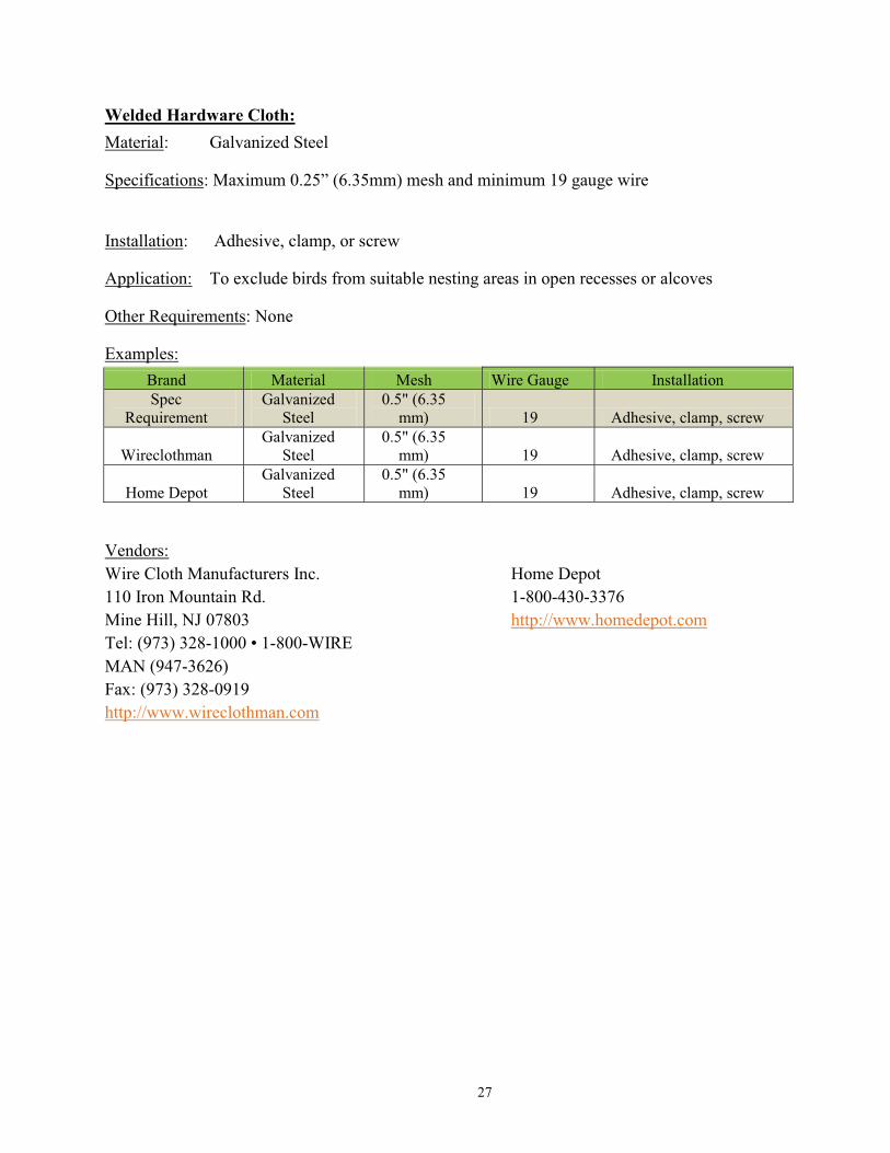
Welded Hardware Cloth:Material: Galvanized Steel
Specifications: Maximum 0.25” (6.35mm) mesh and minimum 19 gauge wire
Installation: Adhesive, clamp, or screw
Application: To exclude birds from suitable nesting areas in open recesses or alcoves
Other Requirements: None
Examples:Brand Material Mesh Wire Gauge InstallationSpec
RequirementGalvanized
Steel0.5" (6.35
mm) 19 Adhesive, clamp, screw
WireclothmanGalvanized
Steel0.5" (6.35
mm) 19 Adhesive, clamp, screw
Home DepotGalvanized
Steel0.5" (6.35
mm) 19 Adhesive, clamp, screw
Vendors:Wire Cloth Manufacturers Inc.110 Iron Mountain Rd.Mine Hill, NJ 07803Tel: (973) 328-1000 • 1-800-WIRE MAN (947-3626)Fax: (973) 328-0919http://www.wireclothman.com
Home Depot1-800-430-3376http://www.homedepot.com

28
Bird-Wire System:Material: Monofilament or stainless steel wire
Specifications: Wire = 0.55 mm to 0.75mm stainless steel wire cable coated with nylon, or manufactured from non-corrosive metal cable or equivalent
Installation: Clamp, Bolt
Application: To exclude birds from suitable nesting and perching areas along the tops of beams and railings. Wire may be installed in a parallel, grid, or spoke configuration to deter birds from nesting, roosting, or loafing in a treated area
Other Requirements: None
Examples:Brand Material Thickness Break-Strength Installation
Spec Requirement
Stainless steel wire coated with nylon, or other non-corrosive metal cable
0.5mm-0.75mm > or = 100 lbs
Crimped and connected to spring
bird-b-gone Bird Wire
Stainless steel wire coated with UV stabilized nylon 0.55mm 110 lbs
Crimped and connected to spring
Bird barrier: birdwire stainless
Stainless steel wire coated with UV stabilized nylon 0.7mm 100 lbs
Crimped and connected to spring
Vendors:Bird-B-Gone(800) 392-6915http://www.birdbgone.com
Bird Barrier20925 Chico StreetCarson, CA 90746800-503-5444http://www.birdbarrier.com

Appendix A - SFOBB Original East Span Piers

Appendix B – 504-ft Span Superstructure Cross Section

Appendix C – Existing Access Platforms, General Locations