water pump
TRANSCRIPT

21/1/2014 Water Pump
https://quickserve.cummins.com/qs2/pubsys2/xml/en/procedures/66/66-008-062-tr-ng.html?q=water%20pump 1/25
008-062 Water Pump
Preparatory Steps
WARNING
Batteries can emit explosive gases. Toreduce the possibility of personal injury,always ventilate the compartmentbefore servicing the batteries. Toreduce the possibility of arcing, removethe negative (-) battery cable first andattach the negative (-) battery cable last.
WARNING
Coolant is toxic. Keep away fromchildren and pets. If not reused, disposeof in accordance with localenvironmental regulations.
WARNING
A small amount of coolant can leakwhen servicing the coolant filter with theshutoff valve in the OFF position. Toreduce the possibility of personal injury,avoid contact with hot coolant.
Disconnect the batteries. Refer tothe original equipment manufacturer(OEM) service manual.Drain the cooling system. Refer toProcedure 008-018 in Section 8.

21/1/2014 Water Pump
https://quickserve.cummins.com/qs2/pubsys2/xml/en/procedures/66/66-008-062-tr-ng.html?q=water%20pump 2/25
Remove
Multiple Turbochargers
Remove the eight allen head capscrewsfrom the two free-end water pipesconnecting to the water pump .
Push the pipes upward and remove the o-rings.
Remove the three allen head capscrewsfrom the lower pump flange.
Loosen and remove the allen headcapscrews that attach the pump to thefree-end housing.
Loosen but do not remove the two uppercapscrews.

21/1/2014 Water Pump
https://quickserve.cummins.com/qs2/pubsys2/xml/en/procedures/66/66-008-062-tr-ng.html?q=water%20pump 3/25
WARNING
This component or assembly weighsgreater than 23 kg [50 lb]. To preventserious personal injury, be sure to haveassistance or use appropriate liftingequipment to lift this component orassembly.
With an approved lifting device attached tothe pump , remove the two remaining allenhead capscrews (1).
Pull the pump straight forward, slightly, toremove the spacers (2).
Remove the pump from the engine.
Take care not to allow the pump drive
gear to come into contact with the free-endhousing. Damage to the gear or housingcan occur.
Single Turbocharger
Remove the eight flanged allen headcapscrews from the two free-end water pipes connecting to the water pump .
Loosen the hose clips and remove thepipes.
Remove the eight flanged Allen headcapscrews that secure the hightemperature water pipe between the water pump (1) and the oil cooler (2),and remove the pipe.

21/1/2014 Water Pump
https://quickserve.cummins.com/qs2/pubsys2/xml/en/procedures/66/66-008-062-tr-ng.html?q=water%20pump 4/25
Loosen and disconnect the oil feed line (1)to the water pump .
Loosen, but do not remove, the four
flanged allen head capscrews (2) thatsecure the water pump to the free-endcasing.
WARNING
This component or assembly weighsgreater than 23 kg [50 lb]. To preventserious personal injury, be sure to haveassistance or use appropriate liftingequipment to lift this component orassembly.
With an approved lifting device attached tothe pump , remove the two remainingcapscrews.
Remove the pump from the engine.
Take care not to allow the pump drive
gear to come into contact with the free endhousing. Damage to the gear or housingcan occur.
Disassemble
Multiple Turbochargers

21/1/2014 Water Pump
https://quickserve.cummins.com/qs2/pubsys2/xml/en/procedures/66/66-008-062-tr-ng.html?q=water%20pump 5/25
Remove the seven allen head capscrewsand lock washers from the end cover.
Discard the lock washers.
Remove the end cover and o-ring.
Discard the o-ring.
Remove the five allen head capscrews andlocking plate from the pump end of theshaft.
Remove the low temperature impeller.
NOTE: If the impeller does not loosen,
gently tap it to rotate it on the shaft.
Remove the two locking rings and discard.
Remove the shaft sleeve and sealassembly.
Remove the rotating half of the mechanicalseal from the sleeve.
Discard the seal.
Remove the seven allen head capscrewsand lock washers that fasten the pump housing to the gear housing.
Discard the lock washers.
NOTE: Cutouts have been cast intothe housings to allow the use of
levers.
Separate the pump housing from the

21/1/2014 Water Pump
https://quickserve.cummins.com/qs2/pubsys2/xml/en/procedures/66/66-008-062-tr-ng.html?q=water%20pump 6/25
drive housing.
Remove the fixed half of the mechanicalseal from the pump housing.
Discard the seal.
NOTE: If the impeller does not loosen,
gently tap it to rotate it on the shaft.
Remove the high temperature impeller andfour locking rings
Remove the seal spacer from the shaft.
Remove the rotating half of the mechanicaloil seal.
Discard the seal.
Remove the four allen head capscrewsand drive gear locking plate from the driveend of the shaft.
Remove the drive gear and four lockingrings.
Discard the locking rings.

21/1/2014 Water Pump
https://quickserve.cummins.com/qs2/pubsys2/xml/en/procedures/66/66-008-062-tr-ng.html?q=water%20pump 7/25
Remove the beveled retaining ring fromthe drive housing.
Remove the shaft assembly from the drivehousing.
Use appropriate tooling to remove thebearings from the shaft.
Discard the bearings.
Remove the stationary portion of themechanical seal from the drive housing.
Remove the lip seal.
Discard the seals.
21/1/2014 Water Pump
https://quickserve.cummins.com/qs2/pubsys2/xml/en/procedures/66/66-008-062-tr-ng.html?q=water%20pump 8/25
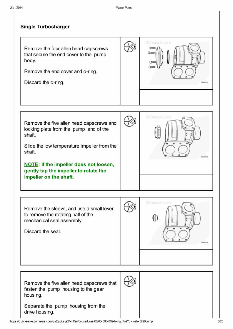
Single Turbocharger
Remove the four allen head capscrewsthat secure the end cover to the pump body.
Remove the end cover and o-ring.
Discard the o-ring.
Remove the five allen head capscrews andlocking plate from the pump end of theshaft.
Slide the low temperature impeller from theshaft.
NOTE: If the impeller does not loosen,
gently tap the impeller to rotate the
impeller on the shaft.
Remove the sleeve, and use a small leverto remove the rotating half of themechanical seal assembly.
Discard the seal.
Remove the five allen head capscrews thatfasten the pump housing to the gearhousing.
Separate the pump housing from thedrive housing.
21/1/2014 Water Pump
https://quickserve.cummins.com/qs2/pubsys2/xml/en/procedures/66/66-008-062-tr-ng.html?q=water%20pump 9/25
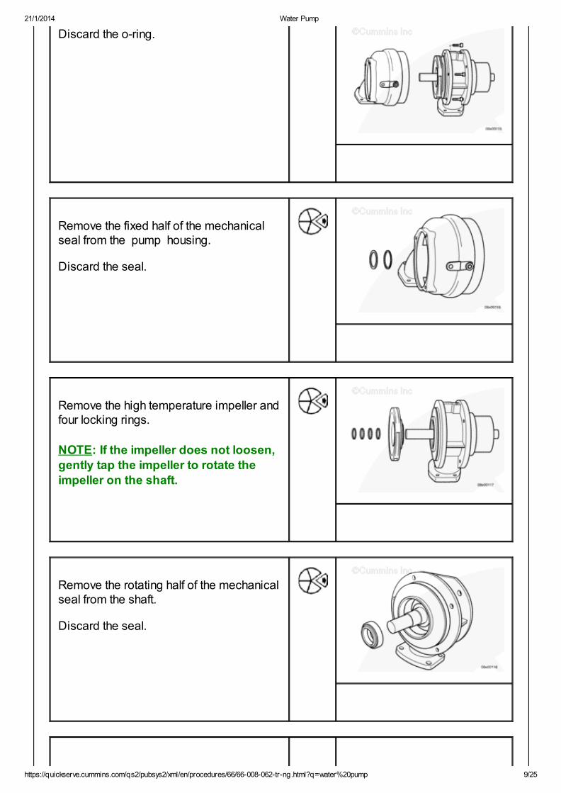
Discard the o-ring.
Remove the fixed half of the mechanicalseal from the pump housing.
Discard the seal.
Remove the high temperature impeller andfour locking rings.
NOTE: If the impeller does not loosen,
gently tap the impeller to rotate the
impeller on the shaft.
Remove the rotating half of the mechanicalseal from the shaft.
Discard the seal.
21/1/2014 Water Pump
https://quickserve.cummins.com/qs2/pubsys2/xml/en/procedures/66/66-008-062-tr-ng.html?q=water%20pump 10/25
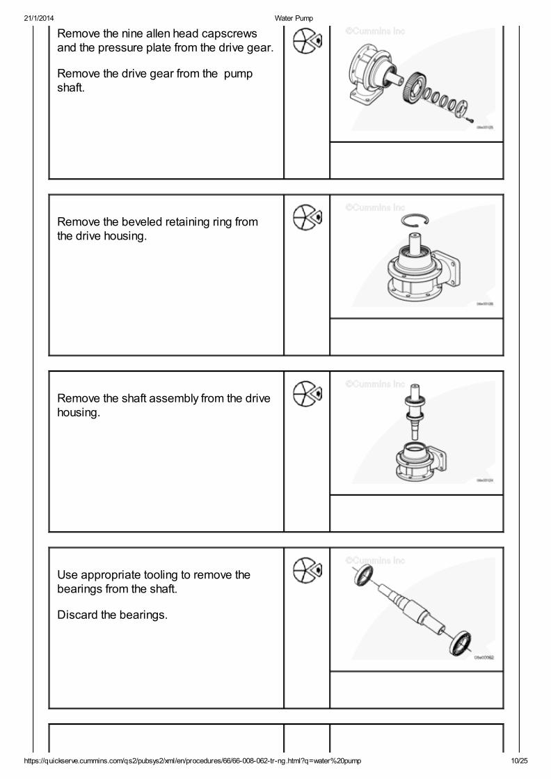
Remove the nine allen head capscrewsand the pressure plate from the drive gear.
Remove the drive gear from the pump shaft.
Remove the beveled retaining ring fromthe drive housing.
Remove the shaft assembly from the drivehousing.
Use appropriate tooling to remove thebearings from the shaft.
Discard the bearings.
21/1/2014 Water Pump
https://quickserve.cummins.com/qs2/pubsys2/xml/en/procedures/66/66-008-062-tr-ng.html?q=water%20pump 11/25
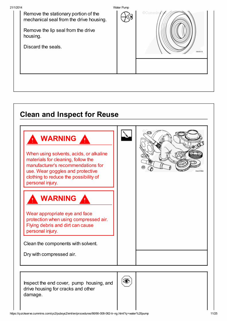
Remove the stationary portion of themechanical seal from the drive housing.
Remove the lip seal from the drivehousing.
Discard the seals.
Clean and Inspect for Reuse
WARNING
When using solvents, acids, or alkalinematerials for cleaning, follow themanufacturer's recommendations foruse. Wear goggles and protectiveclothing to reduce the possibility ofpersonal injury.
WARNING
Wear appropriate eye and faceprotection when using compressed air.Flying debris and dirt can causepersonal injury.
Clean the components with solvent.
Dry with compressed air.
Inspect the end cover, pump housing, anddrive housing for cracks and otherdamage.

21/1/2014 Water Pump
https://quickserve.cummins.com/qs2/pubsys2/xml/en/procedures/66/66-008-062-tr-ng.html?q=water%20pump 12/25
Check the impellers for excessive pitting,corrosion, and cracked or broken blades.
Inspect the shaft bore of the impellers forexcessive scoring.
Check the drive gear for cracked or brokenteeth.
Inspect the shaft bore of the gear forexcessive scoring.
Check the shaft for excessive pitting,corrosion, scoring, and other damage.

21/1/2014 Water Pump
https://quickserve.cummins.com/qs2/pubsys2/xml/en/procedures/66/66-008-062-tr-ng.html?q=water%20pump 13/25
Assemble
Multiple Turbochargers
Press the new bearings onto the shaft.
Check to make sure they rotate freely afterinstallation.
Install a new lip seal into the bearinghousing.
Use clean engine oil to lightly lubricate theshaft assembly and lip seal in the drivehousing.
Install the shaft assembly into the drivehousing.
Install the beveled retaining ring into thedrive housing.
21/1/2014 Water Pump
https://quickserve.cummins.com/qs2/pubsys2/xml/en/procedures/66/66-008-062-tr-ng.html?q=water%20pump 14/25
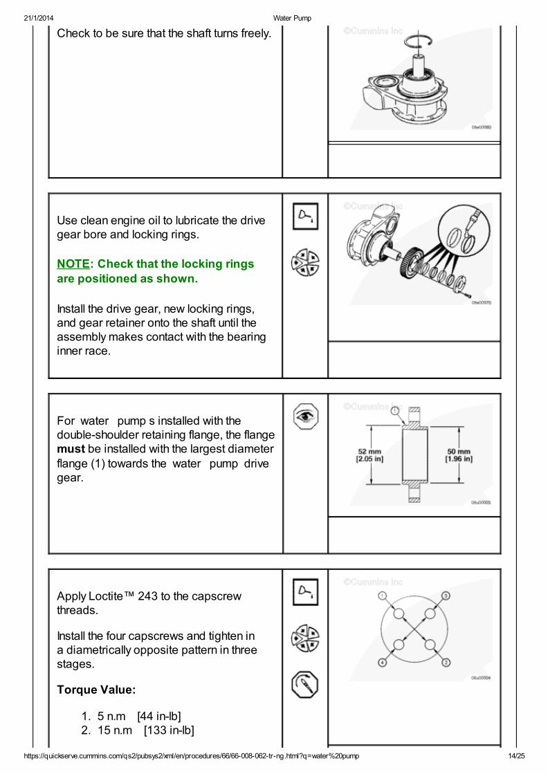
Check to be sure that the shaft turns freely.
Use clean engine oil to lubricate the drivegear bore and locking rings.
NOTE: Check that the locking ringsare positioned as shown.
Install the drive gear, new locking rings,and gear retainer onto the shaft until theassembly makes contact with the bearinginner race.
For water pump s installed with thedouble-shoulder retaining flange, the flangemust be installed with the largest diameter
flange (1) towards the water pump drivegear.
Apply Loctite™ 243 to the capscrewthreads.
Install the four capscrews and tighten ina diametrically opposite pattern in threestages.
Torque Value:
1. 5 n.m [44 in-lb]2. 15 n.m [133 in-lb]

21/1/2014 Water Pump
https://quickserve.cummins.com/qs2/pubsys2/xml/en/procedures/66/66-008-062-tr-ng.html?q=water%20pump 15/25
3. 33 n.m [24 ft-lb]
For water pump s installed with thesingle-shoulder retaining flange (1), theflange must be installed with the shoulder(1) towards the water pump drive gear.
Apply clean engine oil to the flange headscrews.
Do not apply Loctite™ to the capscrew.
Install the four flange head screws andtighten in a diametrically opposite patternin three stages.
Torque Value:
1. 5 n.m [44 in-lb]2. 10 n.m [89 in-lb]3. 25 n.m [221 in-lb]
Use a soapy solution to wet the drivehousing seal bore and stationary half of themechanical seal.
Install the seal in the bore by pressingevenly with finger pressure.
Wipe the face of the seal with a lint-freecloth to remove any oil.
NOTE: Do not touch the seal face. If
contact is made, clean the seal with alint-free cloth to remove any oil.

21/1/2014 Water Pump
https://quickserve.cummins.com/qs2/pubsys2/xml/en/procedures/66/66-008-062-tr-ng.html?q=water%20pump 16/25
Use a soapy solution to wet the seal areaof the shaft.
Install the rotating half of the mechanicalseal onto the shaft.
Install the seal spacer.
Use clean engine oil to lubricate the shaftand locking rings.
Install the high temperature impeller andfour new locking rings onto the shaft asshown.
Use a soapy solution to wet the pump housing seal bore and stationary half of themechanical seal.
Install the seal in the bore by pressingevenly with fingers.
Wipe the face of the seal with a lint-freecloth to remove any oil.
NOTE: Do not allow the seal face ofthe mechanical seal to make contact
with the shaft. If contact is made, cleanthe seal with a lint-free cloth to removeany oil.
Install the o-ring onto the drive housing.
Install the pump housing onto the drivehousing.
Install the Allen head capscrews with new

21/1/2014 Water Pump
https://quickserve.cummins.com/qs2/pubsys2/xml/en/procedures/66/66-008-062-tr-ng.html?q=water%20pump 17/25
lock washers and tighten.
Torque Value: 22 n.m [195 in-lb]
Use a soapy solution to wet the seal areaof the shaft sleeve.
Install the rotating half of the mechanicalseal onto the shaft.
Install the shaft sleeve and seal assembly.
Use clean engine oil to lubricate the shaftand impeller locking rings.
Install the low temperature impeller and twonew locking rings onto the shaft as shown.
Lubricate the threads of the five allen headcapscrews and install.
Tighten the capscrews in a criss-crosspattern.
Torque Value: 17 n.m [150 in-lb]
Install a new end cover and new o-ring.
Install the seven allen head capscrews withnew lock washers and tighten.
Torque Value: 22 n.m [195 in-lb]
Single Turbocharger
Press the new bearings onto the shaft.

21/1/2014 Water Pump
https://quickserve.cummins.com/qs2/pubsys2/xml/en/procedures/66/66-008-062-tr-ng.html?q=water%20pump 18/25
Check to make sure they rotate freely afterinstallation.
Install a new lip seal into the bearinghousing.
Use clean engine oil to lightly lubricate theshaft assembly and lip seal in the drivehousing.
Install the shaft assembly into the drivehousing.
Install the beveled retaining ring into thedrive housing.
Check to be sure the shaft turns freely.

21/1/2014 Water Pump
https://quickserve.cummins.com/qs2/pubsys2/xml/en/procedures/66/66-008-062-tr-ng.html?q=water%20pump 19/25
Use clean engine oil to lubricate the drivegear bore and locking rings.
Install the drive gear, locking rings, andgear retainer onto the shaft.
Position the gear on the shaft so that ameasurement of 103 mm [4.05 inch] isobtained between the pump side of thedrive gear and the mounting face of thedrive housing of the pump .
Install the nine allen head capscrews andtighten in the order shown.
NOTE: Repeat each step of thetightening until each step torque valueis achieved on all capscrews.
Torque Value: 5 n.m [44 in-lb]
Check gear spacing.
Torque Value:
1. 10 n.m [89 in-lb]2. 17 n.m [150 in-lb]
Use a soapy solution to wet the drivehousing seal bore and stationary half of themechanical seal.
Install the seal in the bore by pressingevenly with finger pressure.
Wipe the face of the seal with a lint-freecloth to remove any oil.
NOTE: Do not touch the seal face. Ifcontact is made, clean the seal with a
lint-free cloth to remove any oil.

21/1/2014 Water Pump
https://quickserve.cummins.com/qs2/pubsys2/xml/en/procedures/66/66-008-062-tr-ng.html?q=water%20pump 20/25
Use a soapy solution to wet the seal areaof the shaft.
Install the rotating half of the mechanicalseal onto the shaft.
Install the seal spacer.
Use clean engine oil to lubricate the shaftand locking rings.
Install the high temperature impeller andfour new locking rings onto the shaft asshown.
Use a soapy solution to wet the pump housing seal bore and stationary half of themechanical seal.
Install the seal in the bore by pressingevenly with finger pressure.
Wipe the face of the seal with a lint-freecloth to remove any oil.
NOTE: Do not allow the seal face of
the mechanical seal to make contactwith the shaft. If contact is made, clean
the seal with a lint-free cloth to removeany oil.
Install the o-ring onto the drive housing.
Install the pump housing onto the drivehousing.
Install the five allen head capscrews and
21/1/2014 Water Pump
https://quickserve.cummins.com/qs2/pubsys2/xml/en/procedures/66/66-008-062-tr-ng.html?q=water%20pump 21/25
tighten.
Torque Value: 14 n.m [124 in-lb]
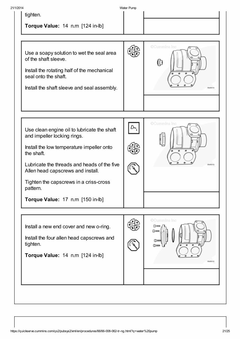
Use a soapy solution to wet the seal areaof the shaft sleeve.
Install the rotating half of the mechanicalseal onto the shaft.
Install the shaft sleeve and seal assembly.
Use clean engine oil to lubricate the shaftand impeller locking rings.
Install the low temperature impeller ontothe shaft.
Lubricate the threads and heads of the fiveAllen head capscrews and install.
Tighten the capscrews in a criss-crosspattern.
Torque Value: 17 n.m [150 in-lb]
Install a new end cover and new o-ring.
Install the four allen head capscrews andtighten.
Torque Value: 14 n.m [124 in-lb]

21/1/2014 Water Pump
https://quickserve.cummins.com/qs2/pubsys2/xml/en/procedures/66/66-008-062-tr-ng.html?q=water%20pump 22/25
Install
Multiple Turbochargers
WARNING
The orifice must be installed prior toinstalling the Gilkes™ pump . Failure todo so will result in a decrease of oilpressure and lubrication to the pump .
NOTE: The orifice installation is onlyrequired when changing from a
Kolmeks Pump (old type) to the newGilkes™ Pump (present production).
Apply several drops of Loctite™ 270 to theorifice, Part Number 4010851, and install itin the water pump oil supply passage.
Install three new o-rings on the pump . Usepetroleum jelly on the o-rings to hold themin place during installation.
WARNING
This component or assembly weighsgreater than 23 kg [50 lb]. To preventserious personal injury, be sure to haveassistance or use appropriate liftingequipment to lift this component orassembly.

21/1/2014 Water Pump
https://quickserve.cummins.com/qs2/pubsys2/xml/en/procedures/66/66-008-062-tr-ng.html?q=water%20pump 23/25
Install the pump onto the free endhousing. Install the spacers and the two topallen head capscrews and hand tighten.
Install the remaining capscrews in the pump and lower flange.
Tighten the mounting capscrews.
Torque Value: 80 n.m [59 ft-lb]
Install two new o-rings and lower the water pipes to the flanges and install theeight allen head capscrews.
Tighten the capscrews.
Torque Value: 80 n.m [59 ft-lb]
Single Turbocharger
WARNING
This component or assembly weighsgreater than 23 kg [50 lb]. To preventserious personal injury, be sure to haveassistance or use appropriate liftingequipment to lift this component orassembly.
Install the coolant pump onto the engine.Take care not to allow the pump drivegear to come into contact with the free endhousing. Damage to the gear or housingcan occur.
Use an approved lifting device to install thecoolant pump .
Install the four mounting flange headcapscrews. Hand-tighten only.

21/1/2014 Water Pump
https://quickserve.cummins.com/qs2/pubsys2/xml/en/procedures/66/66-008-062-tr-ng.html?q=water%20pump 24/25
Connect the oil feed line (1) to the water pump and tighten.
Tighten the four coolant pump flangehead mounting capscrews (2).
Torque Value: 80 n.m [59 ft-lb]
Remove the STORM plug (1) from the sideof free end housing and use a dialindicator tool to check the backlashbetween the pump drive gear and thecrankshaft gear.
Crankshaft Gear Backlash
mm in
0.125 MIN 0.005
0.38 MAX 0.015
Install the high temperature water pipebetween the water pump (1) and thelubricating oil cooler (2).
Install the eight flange head capscrews andtighten.
Torque Value: 195 n.m [144 ft-lb]
Install the two free end water pipes to thecoolant pump .
Install and tighten the eight flange headcapscrews.
Torque Value: 195 n.m [144 ft-lb]

21/1/2014 Water Pump
https://quickserve.cummins.com/qs2/pubsys2/xml/en/procedures/66/66-008-062-tr-ng.html?q=water%20pump 25/25
Finishing Steps
WARNING
Batteries can emit explosive gases. Toreduce the possibility of personal injury,always ventilate the compartmentbefore servicing the batteries. Toreduce the possibility of arcing, removethe negative (-) battery cable first andattach the negative (-) battery cable last.
Fill the high-temperature and low-temperature cooling systems. Referto Procedure 008-018 in Section 8.Connect the batteries. Refer to theOEM service manual.Operate the engine until normaloperating temperatures andpressures are obtained and checkfor leaks.
Last Modified: 18-Jan-2013
Copyright © 2000-2010 Cummins Inc. All rights reserved.