water heater - Продажа webasto evo, air top...
TRANSCRIPT
Feel the drive
WARNING!
Hazard warning:
Incorrect installation or repair of Webasto heating systems may cause a fire or result in the emission of carbon monoxide, which can be fatal. Serious or fatal injuries can be caused as a result.
Specialist company training, technical documentation, specialised tools and equipment are required to install and repair Webasto heating and cooling systems.Only original Webasto parts must be used. For this, also see the catalog of air and water heat-er accessories from Webasto.
NEVER attempt to install or repair Webasto heating or cooling systems if you have not successfully completed the company training and thereby acquired the required tech-nical skills, or if you do not have access to the required technical documentation, tools and equipment needed to carry out correct installation and repairs.
ALWAYS follow all Webasto installation and repair instructions and observe all warnings.
The initial startup is to be executed with the Webasto Thermo Test Diagnosis.
Webasto does not accept any liability for defects and damage that are attributable to installa-tion by untrained staff.
Ident. No.: 1310261B_EN Fee Euro 10.00 © Webasto AG
Citroen C1 / Peugeot 107 / Toyota Aygo
Petrol
from Model Year 2005
For left-hand drive vehicles only
Manual air conditioning
5-gear manual transmission
5-gear MultiMode transmission
Water Heater
Thermo Top E Parking Heater
Thermo Top C Parking Heater
Installation documentation
e1
00 0003
e1
00 0002
Citroen C1 / Peugeot 107 / Toyota Aygo
Table of Contents
Validity 2Heater/Installation Kit 3Foreword 3General Instructions 3Special Tools 3Explanatory notes on document 4Preliminary Work 5Heater installation location 5Electrical system 6Fan control 7Remote option (Telestart) 8
Preparing installation location 9Installing heater 10Coolant circuit 11Combustion air 18Fuel 19Exhaust gas 22Final Work 24Template for fuel standpipe 25Template for fuel-tank sending unit 25Operating Instructions for End Customer 26
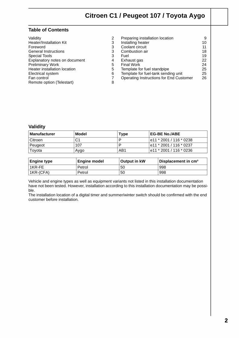
Validity
Vehicle and engine types as well as equipment variants not listed in this installation documentation have not been tested. However, installation according to this installation documentation may be possi-ble.The installation location of a digital timer and summer/winter switch should be confirmed with the end customer before installation.
Manufacturer Model Type EG-BE No./ABE
Citroen C1 P e11 * 2001 / 116 * 0238Peugeot 107 P e11 * 2001 / 116 * 0237Toyota Aygo AB1 e11 * 2001 / 116 * 0236
Engine type Engine model Output in kW Displacement in cm³
1KR-FE Petrol 50 9981KR-(CFA) Petrol 50 998
22
Citroen C1 / Peugeot 107 / Toyota Aygo
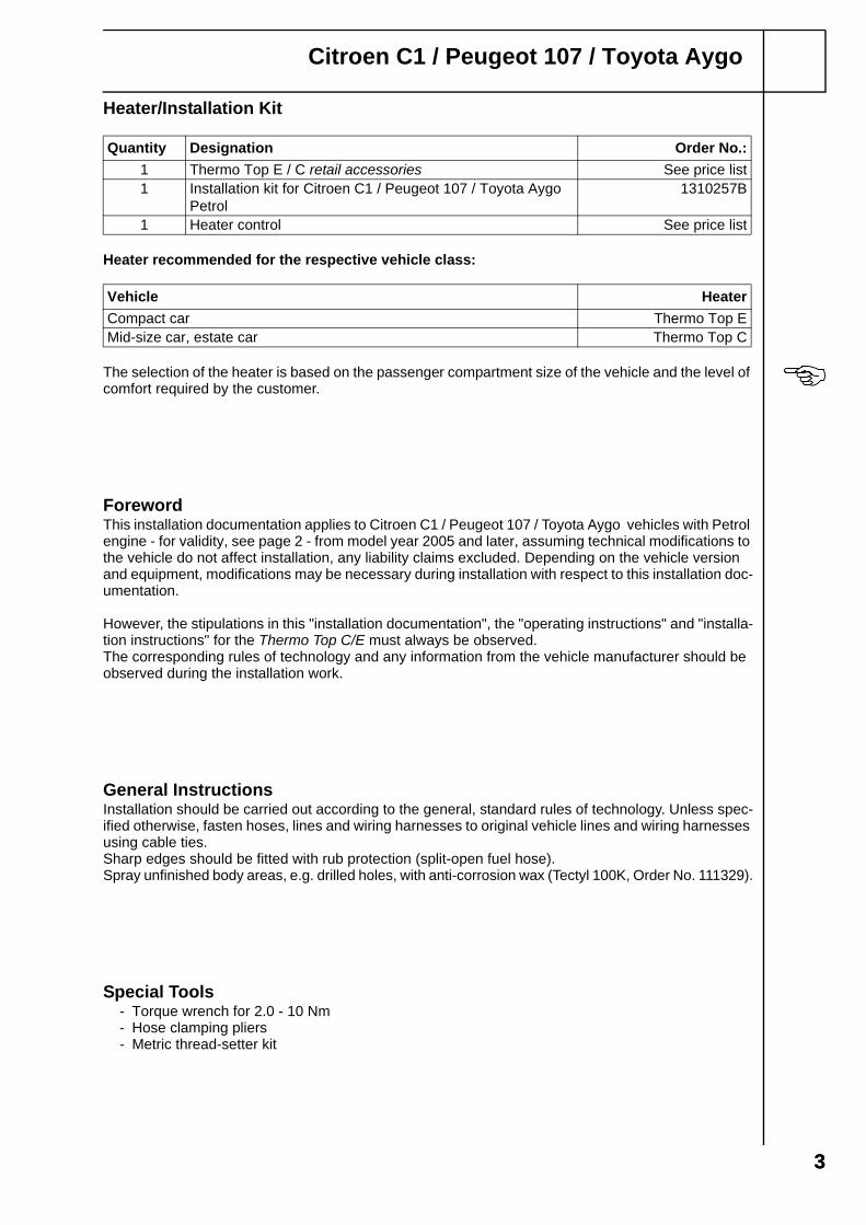
Heater/Installation Kit
Heater recommended for the respective vehicle class:
The selection of the heater is based on the passenger compartment size of the vehicle and the level of comfort required by the customer.
ForewordThis installation documentation applies to Citroen C1 / Peugeot 107 / Toyota Aygo vehicles with Petrol engine - for validity, see page 2 - from model year 2005 and later, assuming technical modifications to the vehicle do not affect installation, any liability claims excluded. Depending on the vehicle version and equipment, modifications may be necessary during installation with respect to this installation doc-umentation.
However, the stipulations in this "installation documentation", the "operating instructions" and "installa-tion instructions" for the Thermo Top C/E must always be observed.The corresponding rules of technology and any information from the vehicle manufacturer should be observed during the installation work.
General InstructionsInstallation should be carried out according to the general, standard rules of technology. Unless spec-ified otherwise, fasten hoses, lines and wiring harnesses to original vehicle lines and wiring harnesses using cable ties.Sharp edges should be fitted with rub protection (split-open fuel hose).Spray unfinished body areas, e.g. drilled holes, with anti-corrosion wax (Tectyl 100K, Order No. 111329).
Special Tools- Torque wrench for 2.0 - 10 Nm- Hose clamping pliers- Metric thread-setter kit
Quantity Designation Order No.:
1 Thermo Top E / C retail accessories See price list1 Installation kit for Citroen C1 / Peugeot 107 / Toyota Aygo
Petrol1310257B
1 Heater control See price list
Vehicle Heater
Compact car Thermo Top EMid-size car, estate car Thermo Top C
33
Citroen C1 / Peugeot 107 / Toyota Aygo
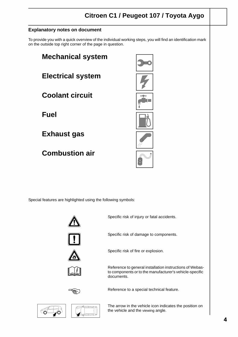
Explanatory notes on document
To provide you with a quick overview of the individual working steps, you will find an identification mark on the outside top right corner of the page in question.
44
Special features are highlighted using the following symbols:
The arrow in the vehicle icon indicates the position on the vehicle and the viewing angle.
Specific risk of injury or fatal accidents.
Specific risk of damage to components.
Specific risk of fire or explosion.
Reference to general installation instructions of Webas-to components or to the manufacturer's vehicle-specific documents.
Reference to a special technical feature.
i
Mechanical system
Electrical system
Coolant circuit
Fuel
Exhaust gas
Combustion air
Citroen C1 / Peugeot 107 / Toyota Aygo
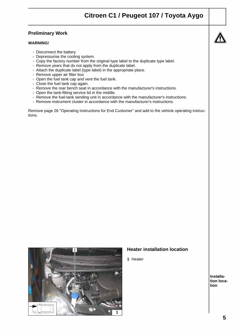
Preliminary Work
WARNING!
- Disconnect the battery - Depressurise the cooling system.- Copy the factory number from the original type label to the duplicate type label.- Remove years that do not apply from the duplicate label.- Attach the duplicate label (type label) in the appropriate place.- Remove upper air filter box- Open the fuel tank cap and vent the fuel tank.- Close the fuel tank cap again.- Remove the rear bench seat in accordance with the manufacturer's instructions.- Open the tank-fitting service lid in the middle.- Remove the fuel-tank sending unit in accordance with the manufacturer's instructions.- Remove instrument cluster in accordance with the manufacturer's instructions.
Remove page 26 "Operating Instructions for End Customer" and add to the vehicle operating instruc-tions.
Heater installation location
1 Heater
Installa-tion loca-tion
1
1
5

Citroen C1 / Peugeot 107 / Toyota Aygo
Electrical system
Wiring harness pass through
1 Protective rubber plug
Digital timer, summer/winter switch option
1 Digital timer2 Summer/winter switch, 12 mm dia. drilled hole
Wiring har-ness rout-ing diagram
Fuse holder, K3 relay
1 Original vehicle bolt2 M5x16 bolt, washers, retaining plate of fuse
holder, perforated bracket (turned by 90°), K3 relay, M5 flanged nut
Earth support point
If bracket at Position 3 is not available, route wiring harnesses into the corrugated tube to the firewall.
1 Original vehicle M6 bolt2 Earth wire of heater
2
1
3
1 2
br
bl
rt/sw
Do not install the metering pump wiring harness until later togeth-er with fuel pipe along the origi-nal vehicle fuel lines on the underbody
i
4
1
2
5
1
2
3
6
Citroen C1 / Peugeot 107 / Toyota Aygo
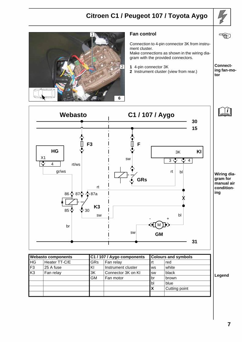
Fan control
Connection to 4-pin connector 3K from instru-ment cluster. Make connections as shown in the wiring dia-gram with the provided connectors.
1 4-pin connector 3K2 Instrument cluster (view from rear.)
Connect-ing fan-mo-tor
Wiring dia-gram for manual air condition-ing
Webasto components C1 / 107 / Aygo components Colours and symbols
Legend
HG Heater TT-C/E GRs Fan relay rt redF3 25 A fuse KI Instrument cluster ws whiteK3 Fan relay 3K Connector 3K on KI sw black
GM Fan motor br brownbl blueX Cutting point
6
1
2
Webasto
31
30
15
C1 / 107 / Aygo
4
HGX1
F3
K3
87a8786
85 30
GM
GRs
F
gr/ws
rt/ws
sw 3
KI
4
3K
blrt
bl
rt
sw
sw
M
+-
br
i
7

Citroen C1 / Peugeot 107 / Toyota Aygo
Remote option (Telestart)
Fasten receiver 2 with adhesive tape.
1 Upper centre console
Installing receiver
1 Antenna
Installing antenna
Only with Telestart T100 HTM
Fasten temperature sensor 2 with adhesive tape.
1 Upper centre console
Installing tempera-ture sensor
1
2 7
i
1
8
1
92
8
Citroen C1 / Peugeot 107 / Toyota Aygo
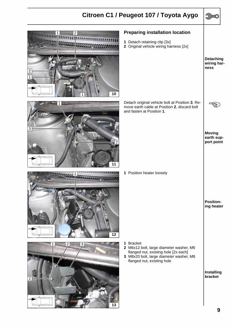
Preparing installation location
1 Detach retaining clip [3x]2 Original vehicle wiring harness [2x]
Detaching wiring har-ness
Detach original vehicle bolt at Position 3. Re-move earth cable at Position 2, discard bolt and fasten at Position 1.
Moving earth sup-port point
1 Position heater loosely
Position-ing heater
1 Bracket2 M6x12 bolt, large diameter washer, M6
flanged nut, existing hole [2x each]3 M8x20 bolt, large diameter washer, M8
flanged nut, existing hole
Installing bracket
10
1 2
1
1
2
11
1
3
2
12
1
13
1 2 3
2
9

Citroen C1 / Peugeot 107 / Toyota Aygo
Installing heater
Mount wiring harness on heater before in-stalling.Tighten Ejot screws to 10 Nm.
1 Bracket2 Ejot screw [2x] Installing
heater
Tighten Ejot screws to 10 Nm.
1 Ejot screw [2x]2 Bracket
Installing heater
14
2
1
2
15
1
2 1
10
Citroen C1 / Peugeot 107 / Toyota Aygo
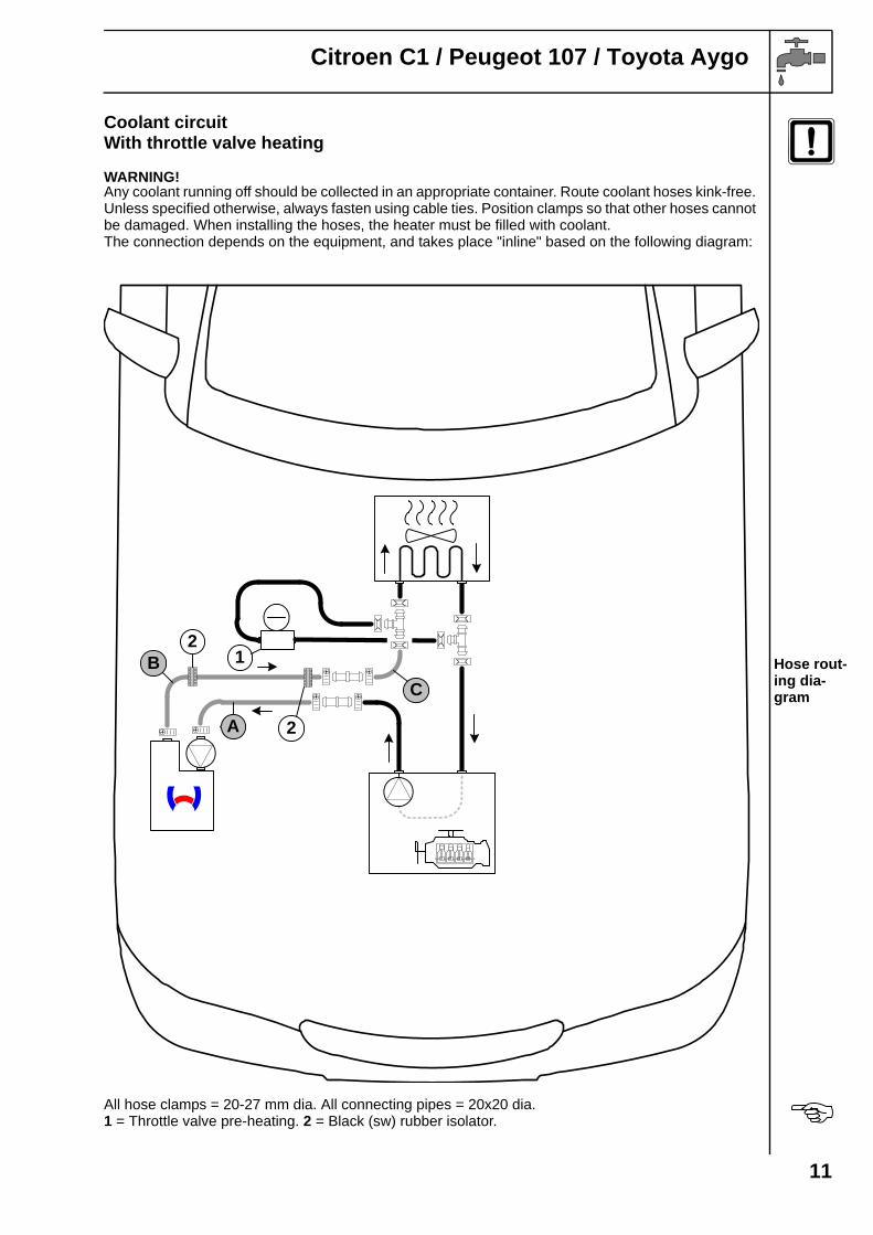
Coolant circuitWith throttle valve heating
WARNING!Any coolant running off should be collected in an appropriate container. Route coolant hoses kink-free. Unless specified otherwise, always fasten using cable ties. Position clamps so that other hoses cannot be damaged. When installing the hoses, the heater must be filled with coolant.The connection depends on the equipment, and takes place "inline" based on the following diagram:
Hose rout-ing dia-gram
All hose clamps = 20-27 mm dia. All connecting pipes = 20x20 dia.1 = Throttle valve pre-heating. 2 = Black (sw) rubber isolator.
B
A
1
C
2
2
11
Citroen C1 / Peugeot 107 / Toyota Aygo
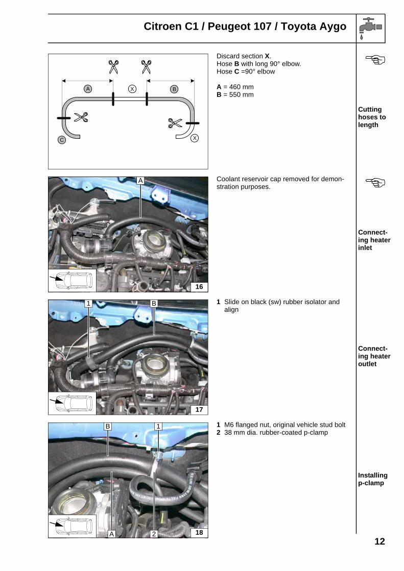
Discard section X.Hose B with long 90° elbow.Hose C =90° elbow
A = 460 mmB = 550 mm
Cutting hoses to length
Coolant reservoir cap removed for demon-stration purposes.
Connect-ing heater inlet
1 Slide on black (sw) rubber isolator and align
Connect-ing heater outlet
1 M6 flanged nut, original vehicle stud bolt2 38 mm dia. rubber-coated p-clamp
Installing p-clamp
A BX
C X
16
A
17
B1
18A
B 1
2
12
Citroen C1 / Peugeot 107 / Toyota Aygo
Pull out hose of engine outlet 3 from T-piece. Spring clip 2 will be reused. Remove hose of heat exchanger inlet 1 with supply line of throttle valve.
Cutting point
Dismantle supply line of throttle valve 4 at po-sition 1, shorten by 20 mm and reinstall.
2 Hose on heat exchanger inlet3 Twist original vehicle spring clips
Preparing hoses
Turn original vehicle spring clips on T-piece to Position 3 downwards.
1 Supply line of throttle valve2 Hose on heat exchanger inlet
Installing hose of heat ex-changer in-let
1 Slide on black (sw) rubber isolator and align
Connect-ing heat exchanger inlet
19
1
3
2
20C
2
3
4
1
3
21
2
C
1
3
22C
1
B
13
Citroen C1 / Peugeot 107 / Toyota Aygo
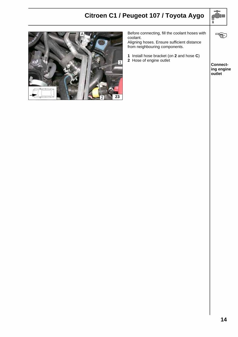
Before connecting, fill the coolant hoses with coolant.Aligning hoses. Ensure sufficient distance from neighbouring components.
1 Install hose bracket (on 2 and hose C)2 Hose of engine outlet
Connect-ing engine outlet
23
1
2
A
14

Citroen C1 / Peugeot 107 / Toyota Aygo
Coolant circuitWithout throttle valve heating
WARNING!Any coolant running off should be collected in an appropriate container. Route coolant hoses kink-free. Unless specified otherwise, always fasten using cable ties. Position clamps so that other hoses cannot be damaged. When installing the hoses, the heater must be filled with coolant.The connection depends on the equipment, and takes place "inline" based on the following diagram:
Hose rout-ing dia-gram
All hose clamps = 20-27 mm dia.All connecting pipes = 18x20 dia.1 = Black (sw) rubber isolator.
B
A
1
15
Citroen C1 / Peugeot 107 / Toyota Aygo
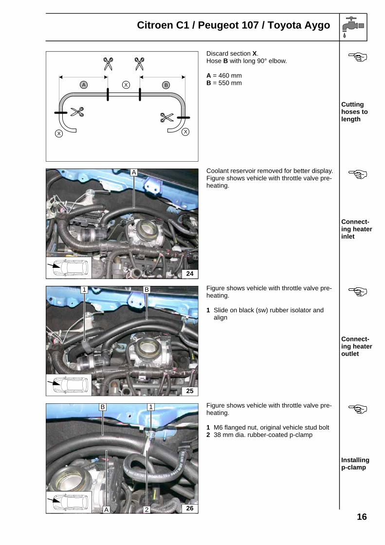
Discard section X.Hose B with long 90° elbow.
A = 460 mmB = 550 mm
Cutting hoses to length
Coolant reservoir removed for better display. Figure shows vehicle with throttle valve pre-heating.
Connect-ing heater inlet
Figure shows vehicle with throttle valve pre-heating.
1 Slide on black (sw) rubber isolator and align
Connect-ing heater outlet
Figure shows vehicle with throttle valve pre-heating.
1 M6 flanged nut, original vehicle stud bolt2 38 mm dia. rubber-coated p-clamp
Installing p-clamp
A BX
X X
24
A
25
B1
26A
B 1
2
16
Citroen C1 / Peugeot 107 / Toyota Aygo
1 Hose of engine outlet2 Hose on heat exchanger inlet
Cutting point
1 Hose of heat exchanger inlet turned up-ward by approx. 30°
Connect-ing heat exchanger inlet
Before connecting, fill the coolant hoses with coolant.Aligning hoses. Ensure sufficient distance from neighbouring components.
1 Install hose bracket (on hose A and B)2 Hose of engine outlet
Connect-ing engine outlet
27
1
2
281
B
29
A 1
2
B
17

Citroen C1 / Peugeot 107 / Toyota Aygo
Combustion air
1 Combustion air pipe a = 310mm
Discard section X Cutting combus-tion air pipe to length
1 Combustion air pipe2 27 mm dia. hose clamp3 Cable tie
Installing combus-tion air pipe
1 Retaining clip in hole2 Silencer
Mounting silencer
a
1
X
30
1 3 2
3
i
31
1
2
18
Citroen C1 / Peugeot 107 / Toyota Aygo
Fuel
CAUTION!Open the vehicle's fuel tank cap, ventilate the tank and then re-close the tank lock.
Catch any fuel running off in an appropriate container.
Install fuel line and metering pump wiring harness so that they are protected against stone impact. Un-less specified otherwise, always fasten using cable ties.Mount the fuel line and wiring harness with rub protection on sharp edges.
WARNING!The fuel line and wiring harness are routed to the metering pump as shown in the wiring harness rout-ing diagram.
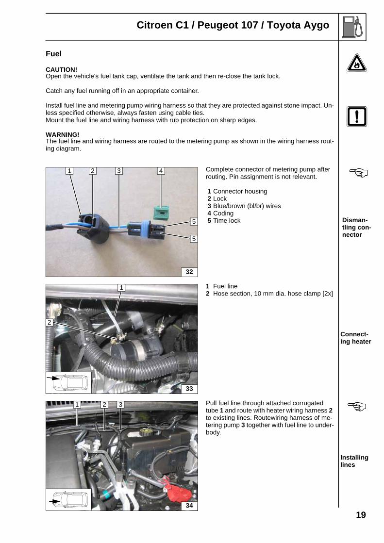
Complete connector of metering pump after routing. Pin assignment is not relevant.
1 Connector housing2 Lock3 Blue/brown (bl/br) wires4 Coding5 Time lock Disman-
tling con-nector
1 Fuel line2 Hose section, 10 mm dia. hose clamp [2x]
Connect-ing heater
Pull fuel line through attached corrugated tube 1 and route with heater wiring harness 2 to existing lines. Routewiring harness of me-tering pump 3 together with fuel line to under-body.
Installing lines
32
1 42 3
5
5
33
1
2
34
1 2 3
19
Citroen C1 / Peugeot 107 / Toyota Aygo
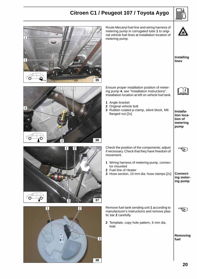
Route Mecanyl fuel line and wiring harness of metering pump in corrugated tube 1 to origi-nal vehicle fuel lines at installation location of metering pump.
Installing lines
Ensure proper installation position of meter-ing pump 4, see "Installation Instructions“.Installation location at left on vehicle fuel tank.
1 Angle bracket2 Original vehicle bolt3 Rubber-coated p-clamp, silent block, M6
flanged nut [2x]Installa-tion loca-tion of metering pump
Check the position of the components; adjust if necessary. Check that they have freedom of movement.
1 Wiring harness of metering pump, connec-tor mounted
2 Fuel line of Heater3 Hose section, 10 mm dia. hose clamps [2x] Connect-
ing meter-ing pump
Remove fuel-tank sending unit 1 according to manufacturer's instructions and remove plas-tic bar 2 carefully.
2 Template, copy hole pattern, 6 mm dia. hole
Removing fuel
35
1
1
36
1 2
3
4
i
37
2
3
1
38
1
3
2
20

Citroen C1 / Peugeot 107 / Toyota Aygo
Shape fuel standpipe 2 according to tem-plate, cut to length and install, see "installa-tion instructions".
1 Fuel-tank sending unit
Installing fuel stand-pipe
Install fuel-tank sending unit according to manufacturer's specifications. Shorten 3.5mm dia. moulded hose by 15mm.
1 Fuel-tank sending unit2 Fuel line3 3.5mm dia. x 4.5mm moulded hose, 9mm
dia. hose clamp, 10mm dia. caillau clamp Connect-ing fuel line
Check the position of the components; adjust if necessary. Check that they have freedom of movement.
1 Hose section, 10 mm dia. hose clamp [2x]2 Fuel line of fuel standpipe
Connect-ing meter-ing pump
39
1
2
40
1
2
3
41
1 2
21
Citroen C1 / Peugeot 107 / Toyota Aygo
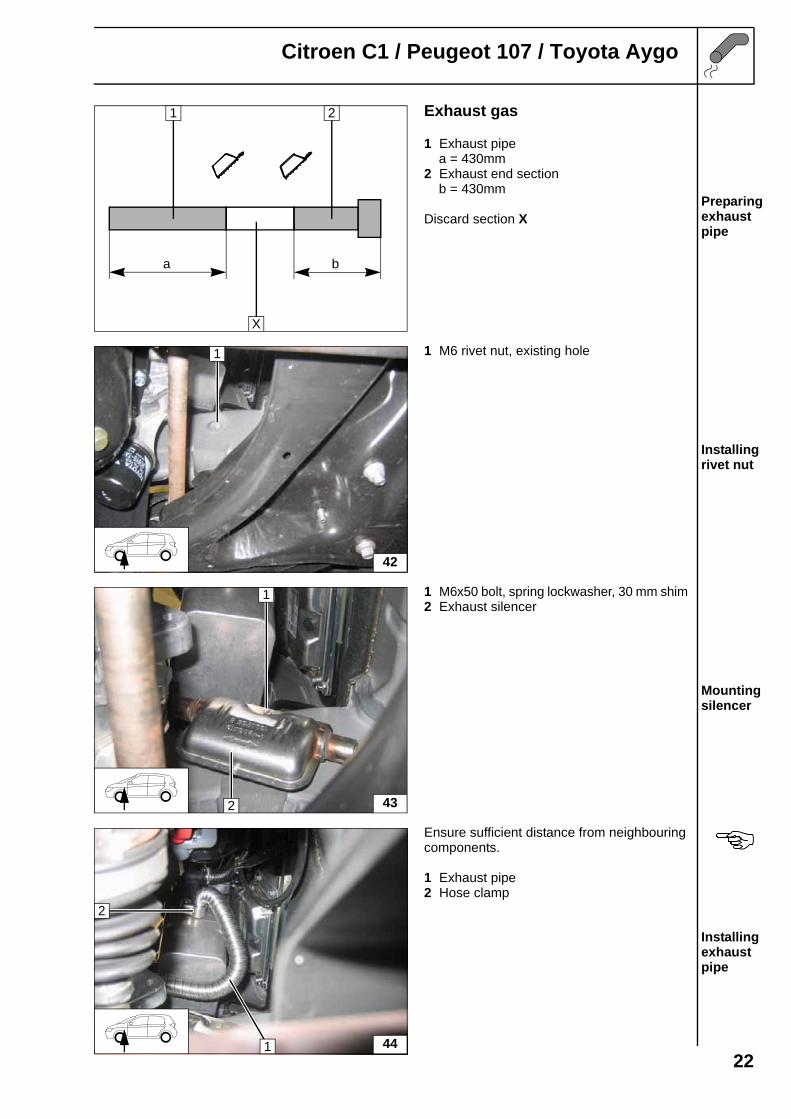
Exhaust gas
1 Exhaust pipe a = 430mm2 Exhaust end section b = 430mm
Discard section XPreparing exhaust pipe
1 M6 rivet nut, existing hole
Installing rivet nut
1 M6x50 bolt, spring lockwasher, 30 mm shim2 Exhaust silencer
Mounting silencer
Ensure sufficient distance from neighbouringcomponents.
1 Exhaust pipe2 Hose clamp
Installing exhaust pipe
a b
1 2
X
42
1
1
2 43
2
1 44
22
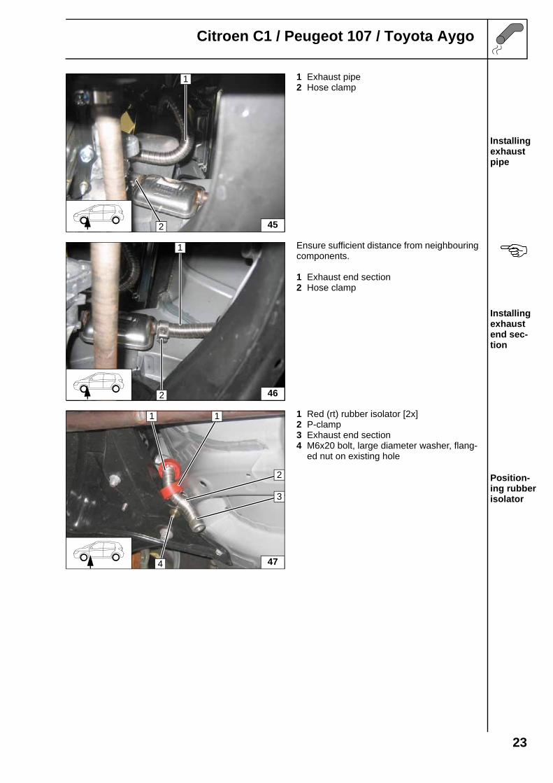
Citroen C1 / Peugeot 107 / Toyota Aygo
1 Exhaust pipe2 Hose clamp
Installing exhaust pipe
Ensure sufficient distance from neighbouring components.
1 Exhaust end section2 Hose clamp
Installing exhaust end sec-tion
1 Red (rt) rubber isolator [2x]2 P-clamp3 Exhaust end section4 M6x20 bolt, large diameter washer, flang-
ed nut on existing hole
Position-ing rubber isolator
1
2 45
1
2 46
47
2
1 1
4
3
23
Citroen C1 / Peugeot 107 / Toyota Aygo
Final Work
WARNING!Mount removed parts in reverse order. Check all hoses, clamps and all electrical connections for firm seating. Insulate all loose wires and tie back.Only use manufacturer-approved coolant. Spray heater components with anti-corrosion wax (Tectyl 100K, Order No. 111329).
- Connect the battery.- Fill and bleed the coolant circuit according to the vehicle manufacturer’s specifications.- Adjust digital timer, teach telestart transmitter- Make settings on A/C control panel according to the "Operating Instructions for End Cus-
tomer".- Place signboard "Switch off parking heater before refuelling" in the area of the filler neck- See installation instructions for initial start-up and function test
i
Printed in Germany 11/2011 Printing: Steffen 241310261B_EN
Feel the driveWebasto AGPostfach 80D-82132 Stockdorf / GermanyNational Hotline: 01805 93 22 78(14 Cent aus dem deutschen Festnetz)Hotfax: 0395 5592 353Hotmail: [email protected]://www.webasto.com
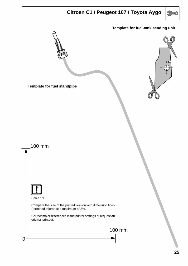
0
100 mm
Scale 1:1
Compare the size of the printed version with dimension liPermitted tolerance a maximum of 2%.
Correct major differences in the printer settings or requesoriginal printout.
Citroen C1 / Peugeot 107 / Toyota Aygo
Template for fuel-tank sending unit
Template for fuel standpipe
25
100 mm
nes.
t an
Citroen C1 / Peugeot 107 / Toyota Aygo
2626
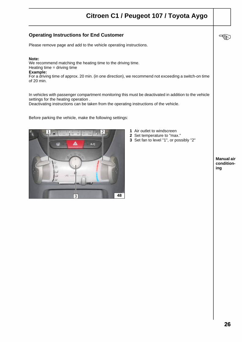
Operating Instructions for End Customer
Please remove page and add to the vehicle operating instructions.
Note:We recommend matching the heating time to the driving time.Heating time = driving timeExample:For a driving time of approx. 20 min. (in one direction), we recommend not exceeding a switch-on time of 20 min.
In vehicles with passenger compartment monitoring this must be deactivated in addition to the vehicle settings for the heating operation .Deactivating instructions can be taken from the operating instructions of the vehicle.
Before parking the vehicle, make the following settings:
1 Air outlet to windscreen2 Set temperature to "max."3 Set fan to level "1", or possibly "2"
Manual air condition-ing
48
1 2
3