water heater unit - · pdf filewater heater unit installation ... function 21 table of...
TRANSCRIPT

Water Heater Unit
Installation Instructions
WARNING!
Hazard warning:
Incorrect installation or repair of Webasto heating systems may cause a fire or result in the emission of carbon monoxide, which can be fatal. Serious or fatal injuries can be caused as a result.
Specialized Webasto training, technical documentation, special tools and equipment are required to install and repair Webasto heating and cooling systems.
NEVER attempt to install or repair Webasto heating or cooling systems if you have not successfully completed the company training and thereby acquired the required technical skills or if you do not have access to the required technical documentation, tools and equipment needed to carry out correct installation and repairs.
ALWAYS follow all Webasto installation and repair instructions and observe all warning instructions.
Webasto does not accept any liability for defects and damage that are attributable to an installation by untrained staff.
Feel the drive
Mercedes ML (W164) / GL (X164)Gasoline and dieselFrom model year 2005For left-hand drive vehicles only
Thermo Top V Auxiliary Heating
DOC. P/N 5001216A Printed in USA Webasto Product N.A., Inc.

2
Mercedes ML (W164) / GL (X164)
Validity
Vehicle and engine types, equipment variants as well as national specifications, which are not listed in these installation instructions, have not been tested.Installation according to these installation instructions may, however, be possible.
Manufacturer Model Type EG-BE No. / ABEDaimler-Chrysler M class W164 e1 * 2001 / 116 * 0315...Daimler-Chrysler GL class X164 e1 * 2001 / 116 * 0340...
Engine type Engine Power in kW Engine capacity in cm³V6 Diesel 140 2987V6 Diesel 165 2987V6 Gasoline 200 3498V8 Gasoline 225 4966
Validity 2Heater Unit / Installation Kit 3Foreword 3General Instructions 3Special Tools 3Explanatory Notes on the Document 4Preliminary Work 5Heater Unit Installation Location 5Harness Routing and Installation 6CAN connection 7Remote Activation Installation (If Equipped) 8
Preparing the Heater Unit 10Preparing the Installation Location 11Preassembly of the Heater Unit 12Installing the Heater Unit 12Exhaust Connection 13Water Connection 14Fuel Connection 19Final Work 21Programming the T90 Remote Receiver 21Enabling the Factory Equipped Timer Function 21
Table of Contents
33
Mercedes ML (W164) / GL (X164)
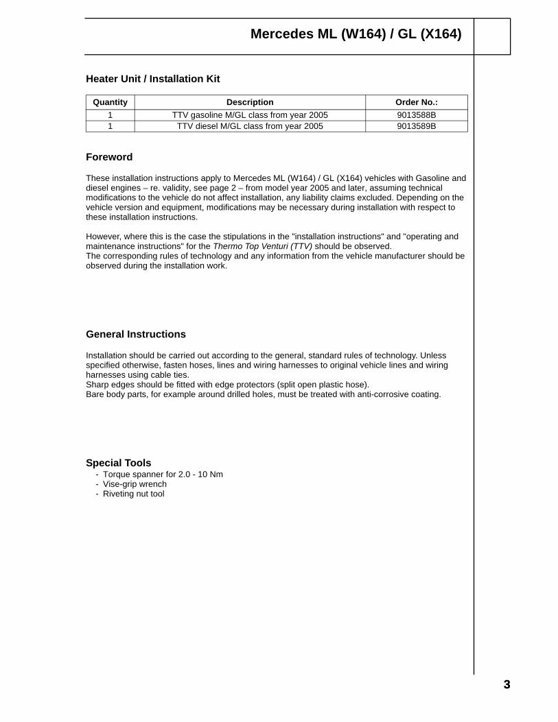
Heater Unit / Installation Kit
Foreword
These installation instructions apply to Mercedes ML (W164) / GL (X164) vehicles with Gasoline and diesel engines – re. validity, see page 2 – from model year 2005 and later, assuming technical modifications to the vehicle do not affect installation, any liability claims excluded. Depending on the vehicle version and equipment, modifications may be necessary during installation with respect to these installation instructions.
However, where this is the case the stipulations in the "installation instructions" and "operating and maintenance instructions" for the Thermo Top Venturi (TTV) should be observed.The corresponding rules of technology and any information from the vehicle manufacturer should be observed during the installation work.
General Instructions
Installation should be carried out according to the general, standard rules of technology. Unless specified otherwise, fasten hoses, lines and wiring harnesses to original vehicle lines and wiring harnesses using cable ties.Sharp edges should be fitted with edge protectors (split open plastic hose).Bare body parts, for example around drilled holes, must be treated with anti-corrosive coating.
Special Tools- Torque spanner for 2.0 - 10 Nm- Vise-grip wrench- Riveting nut tool
Quantity Description Order No.:1 TTV gasoline M/GL class from year 2005 9013588B1 TTV diesel M/GL class from year 2005 9013589B
44
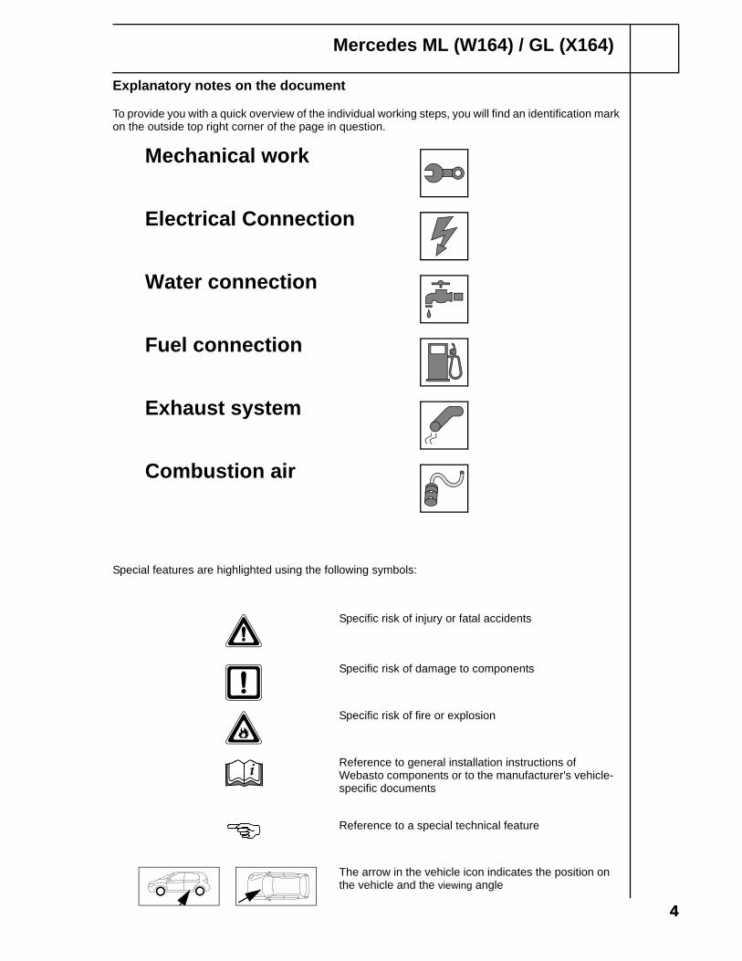
Special features are highlighted using the following symbols:
Mechanical work
Electrical Connection
Water connection
Fuel connection
Exhaust system
Combustion air
The arrow in the vehicle icon indicates the position on the vehicle and the viewing angle
Mercedes ML (W164) / GL (X164)
Specific risk of injury or fatal accidents
Specific risk of damage to components
Specific risk of fire or explosion
Reference to general installation instructions of Webasto components or to the manufacturer's vehicle-specific documents
Reference to a special technical feature
i
Explanatory notes on the document
To provide you with a quick overview of the individual working steps, you will find an identification mark on the outside top right corner of the page in question.
5
Mercedes ML (W164) / GL (X164)
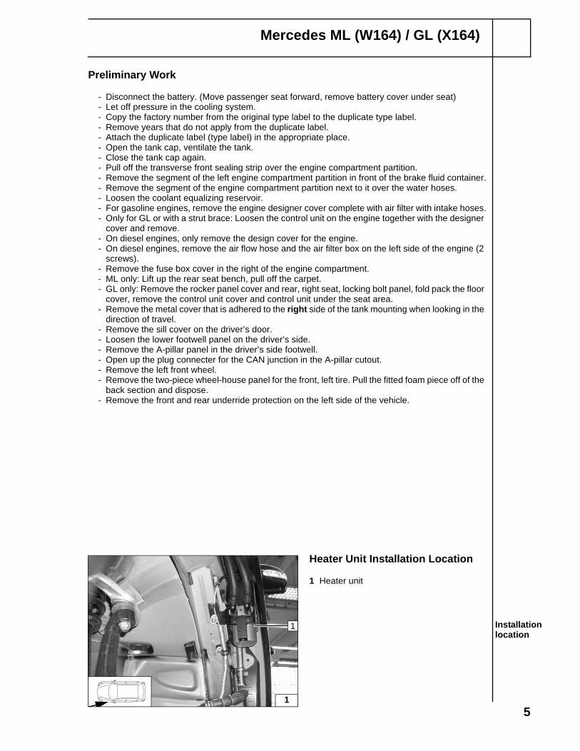
Heater Unit Installation Location
1 Heater unit
Installation location
1
1
Preliminary Work
- Disconnect the battery. (Move passenger seat forward, remove battery cover under seat)- Let off pressure in the cooling system.- Copy the factory number from the original type label to the duplicate type label.- Remove years that do not apply from the duplicate label.- Attach the duplicate label (type label) in the appropriate place.- Open the tank cap, ventilate the tank.- Close the tank cap again.- Pull off the transverse front sealing strip over the engine compartment partition.- Remove the segment of the left engine compartment partition in front of the brake fluid container.- Remove the segment of the engine compartment partition next to it over the water hoses.- Loosen the coolant equalizing reservoir.- For gasoline engines, remove the engine designer cover complete with air filter with intake hoses.- Only for GL or with a strut brace: Loosen the control unit on the engine together with the designer
cover and remove.- On diesel engines, only remove the design cover for the engine.- On diesel engines, remove the air flow hose and the air filter box on the left side of the engine (2
screws).- Remove the fuse box cover in the right of the engine compartment.- ML only: Lift up the rear seat bench, pull off the carpet.- GL only: Remove the rocker panel cover and rear, right seat, locking bolt panel, fold pack the floor
cover, remove the control unit cover and control unit under the seat area.- Remove the metal cover that is adhered to the right side of the tank mounting when looking in the
direction of travel.- Remove the sill cover on the driver’s door.- Loosen the lower footwell panel on the driver’s side.- Remove the A-pillar panel in the driver’s side footwell.- Open up the plug connecter for the CAN junction in the A-pillar cutout.- Remove the left front wheel.- Remove the two-piece wheel-house panel for the front, left tire. Pull the fitted foam piece off of the
back section and dispose.- Remove the front and rear underride protection on the left side of the vehicle.

6
Mercedes ML (W164) / GL (X164)
Electrical Connection
Fuse holder, power supply
1 20A fuse holder2 Spacer washer, M6x16 bolt3 Fuse box positive connection 4 Protective rubber sleeve
Remote receiver fuse holder
1 Fuse holder
Wiring harness diagram
Ground connection
1 Grounding point
Wiring harness feed-through
1 Protective rubber sleeve2 Wiring harness
2
12
4
3
1
3
br
bl
Install the fuel pump wiring harness together with fuel line along the original vehicle fuel lines on the underbody.
4
1
5
2
1

7
Mercedes ML (W164) / GL (X164)
Harness Routing and InstallationInstall the wiring harness for the heater, fuel pump, and solenoid valve down into the wheelhouse. Install the wiring harness for the remote receiver/CAN connection (1) in the harness feed-through.
1 Remote receiver/CAN wiring harnessInstalling wiring harnesses
CAN Connection
Plug the CAN connection plug (1) in the free slot in the plug connector (2).
1 CAN connection plug2 Plug connector CAN
connection
6
1
7
12

8
Mercedes ML (W164) / GL (X164)
Remote Activation Installation (If Equipped)Using butt splices provided, connect the Y-adapter harness to heater harness. Splice:
- red to red- yellow to yellow- brown to brown
Plug Y-adapter harness (4) connectors into the T90 remote receiver (5) and the SPAL remote receiver harness (3).1 Antenna plug2 Butt connectors [3x]3 SPAL remote harness connector4 Y-Adapter harness5 T90 remote receiver
Remote activation connection
Attach the T90 remote receiver housing (1) to the left side footwell panel with Velcro strips.
1 T90 remote receiverAssem-bling the T90 remote receiver
Fasten the SPAL remote receiver (1) to the engine compartment rear bulkhead insulation with a Velcro strip.
1 SPAL remote receiver Assem-bling the SPAL remote
Mount the SPAL remote receiver antenna (1) on the front windshield.
1 AntennaAssem-bling the antenna
84
2
1
5
3
9
1
10
1
11
1
9
Mercedes ML (W164) / GL (X164)
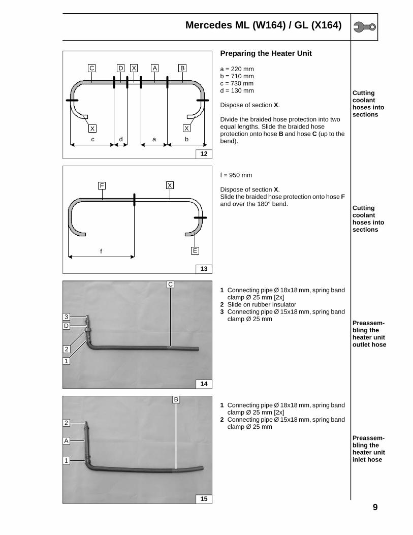
Preparing the Heater Unit
a = 220 mmb = 710 mmc = 730 mmd = 130 mm
Dispose of section X.
Divide the braided hose protection into two equal lengths. Slide the braided hose protection onto hose B and hose C (up to the bend).
Cutting coolant hoses into sections
f = 950 mm
Dispose of section X.Slide the braided hose protection onto hose F and over the 180° bend. Cutting
coolant hoses into sections
1 Connecting pipe Ø 18x18 mm, spring band clamp Ø 25 mm [2x]
2 Slide on rubber insulator3 Connecting pipe Ø 15x18 mm, spring band
clamp Ø 25 mm Preassem-bling the heater unit outlet hose
1 Connecting pipe Ø 18x18 mm, spring band clamp Ø 25 mm [2x]
2 Connecting pipe Ø 15x18 mm, spring band clamp Ø 25 mm
Preassem-bling the heater unit inlet hose
X
C D A B
c d a b
X
X
12
XF
f E
13
D
14
3
C
1
2
1
B
A
2
15

10
Mercedes ML (W164) / GL (X164)
1 Spring band clamp Ø 25 mm
Preassem-bling the F hose
Preparing the Installation Location
Insert the rubber stopper (2) on the heater unit bracket into the indicated opening in the body. Transfer the hole image for the fastening points (1) [2x]. Drill Ø 9.2 mm holes, fasten rivet nuts.
1 Heater fastening points 2 Rubber stopper
Inserting rivet nuts
Slip the exhaust pipe (4) onto the exhaust connecting piece (1). Transfer the hole location for fastening points to positions 2 and 3. Drill Ø 9.2 mm holes, fasten M6 rivet nuts.
1 Exhaust connecting piece 4 Exhaust pipe
Drilling the exhaust fastening points
Slip exhaust silencer (2) onto the exhaust tube (3). Transfer the hole location for the fastening point for brace (1). Drill Ø 9.2 mm hole, fasten M6 rivet nut.
1 Brace 2 Exhaust silencer (muffler) 3 Exhaust tube
Drilling the exhaust fastening points
16
1 F
17
2
1
1
18
4
23
1
191
2
3

11
Mercedes ML (W164) / GL (X164)
Pre-assembly of the Heater Unit
Install the preassembled hoses and align according to the picture. Connect the fuel line to the heater using the fuel line coupler and clamps provided.
1 Preassembled heater unit inlet hose 2 Preassembled heater unit outlet hose 3 Spring band clamp Ø 25 mm [2x]4 Fuel line, fuel line coupler, clamps [2x]
Assem-bling the coolant hoses
Installing the Heater Unit
Plug harness connectors into the heater unit, loosely tighten the heater unit on the upper bolt. Route the coolant hoses into the engine compartment. Fasten the fuel line and the fuel pump wiring harness in the protective hose with a tube clamp on the lower bolt.
1 Fuel line fastening lug2 Rubberized tube clamp Ø 15 mm3 Heat protection hose4 Edged bolt M6x25 with washer [2x]
Installing the heater unit
Fasten the coolant hoses and heater unit wiring harness to the openings in the body with cable ties.
Fastening coolant hoses
Apply edge protection at locations shown in Figure 23.
1 Edge protection
Assem-bling the edge protection
20
1 2 3
4
21
2
43
1
22
231
12
Mercedes ML (W164) / GL (X164)
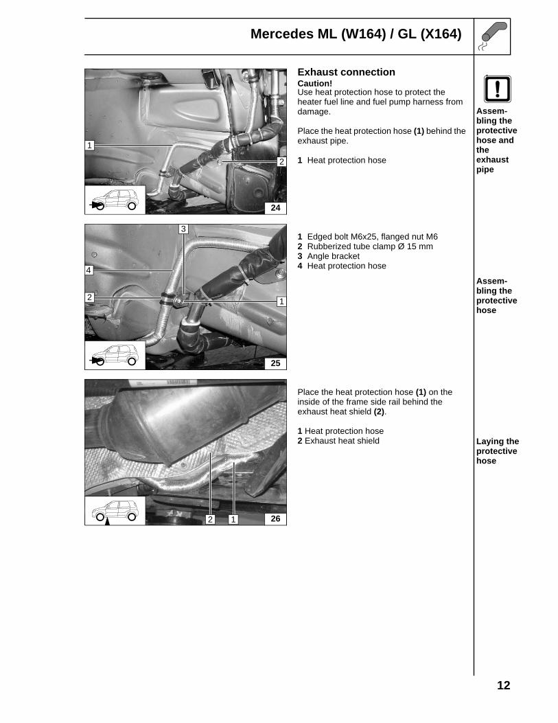
Exhaust connectionCaution!Use heat protection hose to protect the heater fuel line and fuel pump harness from damage.
Place the heat protection hose (1) behind the exhaust pipe.
1 Heat protection hose
Assem-bling the protective hose and the exhaust pipe
1 Edged bolt M6x25, flanged nut M62 Rubberized tube clamp Ø 15 mm3 Angle bracket4 Heat protection hose
Assem-bling the protective hose
Place the heat protection hose (1) on the inside of the frame side rail behind the exhaust heat shield (2).
1 Heat protection hose2 Exhaust heat shield Laying the
protective hose
24
1
2
25
2 1
3
4
1 262

13
Mercedes ML (W164) / GL (X164)
Water Connection
Caution!
Any coolant run off should be collected using an appropriate container!Install hoses so that they are kink-free. Unless specified otherwise, always fasten using cable ties. Position spring band clamps so that no other hose can be damaged!The connection is based on the following diagram:
Water installationdiagram
Wärme-tauscher
Motor
Ø 15x18
Ø 15x18Ø 22
Ø 22Bypass
A
B
C
E
F
D1
Heatexchanger
1 is the original vehicle circulation pump All undesignated spring band clamps = Ø 25 mm!All undesignated connecting pipes are Ø 18x18.

14
Mercedes ML (W164) / GL (X164)
All vehicles
Turn the 90° bend (2) on the equalizing reservoir by 180°.
1 Heat exchanger outlet hose
Integration point
Fasten the heater unit outlet hose D on the turned hose bend. Position the rubber insulator (1) where shown in Figure 28.
1 Rubber insulator Connec-ting to the heater unit outlet
Fasten the heater unit inlet hose A on the heat exchanger inlet hose (1). Align the spacer bracket (2).
1 Heat exchanger inlet hose2 Spacer bracket Connec-
ting to the heater unit inlet
1 Bolt M5x12, spring washer2 Solenoid valve
Assem-bling the solenoid valve
27
2
1
cut
28
D1
29
1 2 A
30
1
2
15
Mercedes ML (W164) / GL (X164)
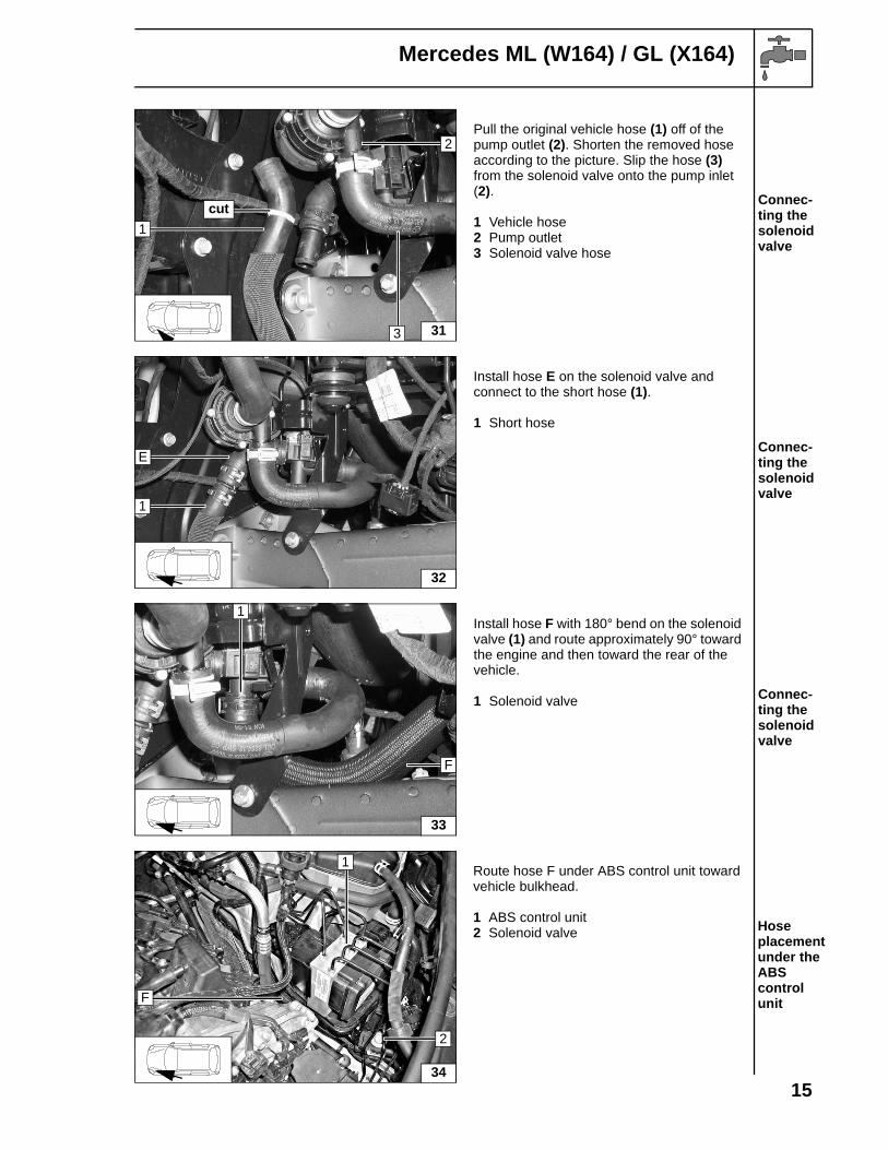
Pull the original vehicle hose (1) off of the pump outlet (2). Shorten the removed hose according to the picture. Slip the hose (3) from the solenoid valve onto the pump inlet (2).
1 Vehicle hose2 Pump outlet3 Solenoid valve hose
Connec-ting the solenoid valve
Install hose E on the solenoid valve and connect to the short hose (1).
1 Short hose
Connec-ting the solenoid valve
Install hose F with 180° bend on the solenoid valve (1) and route approximately 90° toward the engine and then toward the rear of the vehicle.
1 Solenoid valve Connec-ting the solenoid valve
Route hose F under ABS control unit toward vehicle bulkhead.
1 ABS control unit2 Solenoid valve Hose
placement under the ABS control unit
31
1
3
2
cut
32
1
E
33
1
F
34
1
2
F

16
Mercedes ML (W164) / GL (X164)
Remove coolant hose (1) from heat exchanger inlet. Do not discard the spring band clamp, it will be used again.
1 Coolant hose
Splitting point
Cut off the disassembled coolant hose (1) on the side with the small diameter and assemble.
1 Coolant hose Preassem-bling the check-back valve
Connect the check-back valve to the hose (2) and the connecting piece to the heat exchanger.
1 Original vehicle spring band clamp2 Coolant hose Assem-
bling the check-back valve
Run the hose F along the air conditioning line. Position the rubber edge protector (1) for the vacuum line over hose F.
1 Rubber edge protector Installing in the engine compart-ment
35
1
cut
361
min. 60 mm
37
1
2
38
F
1

17
Mercedes ML (W164) / GL (X164)
The figure shows the GL model.
1 Spacer bracket [2x]
Placement on the air condi-tioner line
Connect hose F to the check-back valve. Align the spacer bracket (1) [2x].
1 Spacer brackets
Connec-ting the check-back valve
Only for ML350 gasoline
Slide rubber insulator (1) onto hose F. Position the hose F on the bolt for the original vehicle heat protection sheet with the tube clamp (2). Position the rubber profile on the air conditioner line.
1 Rubber insulator2 Tube clamp
Installing in the engine compart-ment
Cut hose F into sections if necessary and connect to the check-back valve (1).
1 Check-back valve
Connec-ting the check-back valve
1 F 1
39
F
1
402 1
41
1
F

18
Mercedes ML (W164) / GL (X164)
Fuel Connection
CAUTION!Open the vehicle's tank-cap lock, ventilate the tank and then re-close the tank lock.
Catch any fuel running off with an appropriate container.
Install fuel line and fuel pump wiring harness so that they are protected against stone impact. Unless specified otherwise, always fasten using cable ties.Fit the fuel line and wiring harness with edge protectors around sharp edges.
WARNING!The fuel line and wiring harness to the fuel pump should be installed based on the wiring harness installation diagram.
1 Hose section [2x]2 Fuel pump connector (pressure end)3 Fuel pump bracket4 Fuel line clamp Ø 10 mm (white color
identification) [2x] Preassem-bling the meteringpump
Drill Ø 9.2 mm hole at position 1 in the tank retainer strap and insert the rivet nut.
1 Edged bolt M6x25 to rivet nut2 Fuel pump bracket
Assem-bling the fuel pump
Install the fuel pump wiring harness (1) and the fuel line (3) in the original vehicle line guides (2).
1 Fuel pump harness2 Vehicle line guides3 Fuel line Installing
pipes
42
1 2 3 4
4 1
43
1
2
443 12

19
Mercedes ML (W164) / GL (X164)
Run the fuel line from the heater unit in the original vehicle line guides (1).
1 Vehicle line guides
Fastening the lines
Slide the smaller diameter hose section (3) on the fuel line connector (1). Insert the fuel line in the other side of the hose section (3). Pull the protective hose (5) over the fuel line.
2 Fuel line clamp Ø 8 mm (yellow color identification)
4 Fuel line clamp Ø 10 mm (white color identification) [2x]
Preassem-bling the tank extracting device
Cut off the end of the protruding fuel nipple (1) on the fuel sender (2).
1 Fuel nipple 2 Fuel sender
Preparing the fuel sender
Push the fuel line connector (1) onto the fuel nipple until you hear an audible snap. Apply sealant to metal cover and reinstall over fuel sender (2).
1 Fuel line connector 2 Fuel sender
Connec-ting the fuel line
45
1
46
1 2 3 54
471
2
48
1
2
20
Mercedes ML (W164) / GL (X164)
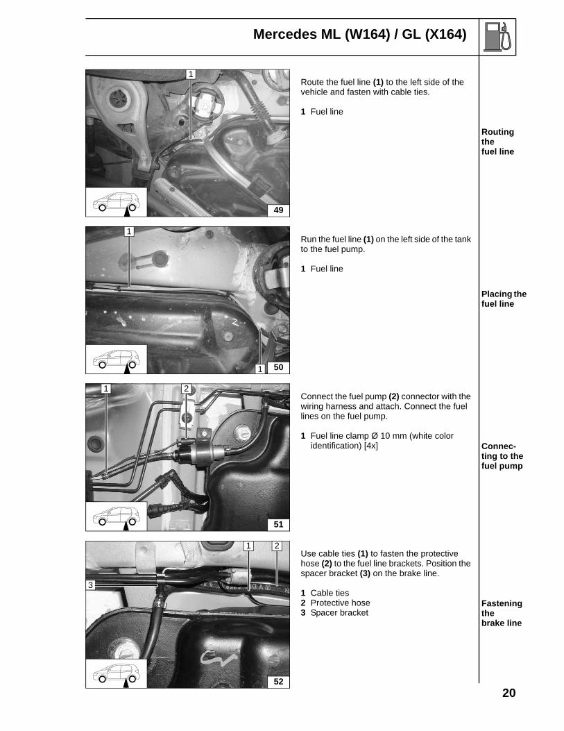
Route the fuel line (1) to the left side of the vehicle and fasten with cable ties.
1 Fuel line
Routing the fuel line
Run the fuel line (1) on the left side of the tank to the fuel pump.
1 Fuel line
Placing the fuel line
Connect the fuel pump (2) connector with the wiring harness and attach. Connect the fuel lines on the fuel pump.
1 Fuel line clamp Ø 10 mm (white color identification) [4x] Connec-
ting to the fuel pump
Use cable ties (1) to fasten the protective hose (2) to the fuel line brackets. Position the spacer bracket (3) on the brake line.
1 Cable ties2 Protective hose3 Spacer bracket
Fastening the brake line
1
49
50
1
1
51
1 2
52
3
1 2

21
Mercedes ML (W164) / GL (X164)
Final Work
Reassemble components in reverse order.Check that all hose lines, hose, spring band clamps and fuel line clamps, and all electrical connections are securely fastened.Secure all loose lines using cable ties.Check and adjust any disassembled or loose headlights after installation.Spray heating unit components with anti-corrosion compound.
- Start engine, bleed coolant circuit according to the vehicle manufacturer's specifications, top up with coolant.
- Warning! Only use manufacturer-approved coolant. - Check the coolant system for leaks according to the manufacturer’s instructions.- Attach the "Switch off auxiliary heating before re-fuelling" sticker in the tank flap or the left side of
the B-pillar.- Clear any diagnostic codes that may have set during installation for the heater and air conditioning
system.- Check that the auxiliary heater operates properly, see operating instructions / installation
instructions.
Programming the T90 Remote Receiver
AttentionEnsure the SPAL receiver is plugged into the Y-adapter harness going to the T90 remote receiver.Read through all steps before beginning programming procedure, some of the steps are time critical.
- Connect the battery.- Disconnect the harness going to the T90 remote receiver and reconnect after 5 seconds or remove
the T90 remote receiver fuse (1A) from the fuse holder and install after 5 seconds.- Within 7 seconds, press the “on” button on the SPAL hand-held transmitter for about 1 second.- Check for proper operation of the transmitter and repeat procedure if necessary.
Enabling the Factory Equipped Timer Function
The Mercedes M Class comes factory equipped with a HVAC controller that can be programmed to control the Webasto heater On / Off times. STAR Diagnostics must be used to program this feature for the heater. Only a certified Mercedes dealership has the necessary diagnostic tool and information to properly set up these heater functions.Refer to “Auxiliary heating / ventilation” in the vehicle’s owners manual for specific instructions on how to set heater On / Off times.
Heater Operation When Ambient Temperature is Over 15°CAttentionIf the heater is turned on by the remote receiver or the factory timer and the ambient temperature is above 15°C (59°F) the heater will operate in ventilation mode only.If the heater is commanded on by the diagnostic tool and the ambient temperature is above 15°C (59°F) the heater will run, but the coolant check valve will not open.

Mercedes ML (W164) / GL (X164)
Notes:

Mercedes ML (W164) / GL (X164)
Documentation Feedback Form
Detailed user feedback is extremely valuable to us in producing accurate, comprehensive, and useful documentation. Please complete the relevant parts of the form below; your comments and suggestions will help us improve our documentation. Thank you.
Unsatisfactory Excellent
Please rate the overall usefulness of the documentation. 1 2 3 4 5
Rate the completeness and clarity of the instructions: did the procedures provide enough detail? 1 2 3 4 5
What could be added or clarified?
Please list any other comments, concerns, or suggestions.
Please provided contact information below.
Name:
Company Name:
City / State:
Phone:
Email:
Mail to:Webasto Product N. A., Inc.15083 North RoadFenton, MI 48430Attention: Documentation Group
orFax to: (810) 593-6137

Org.06/2006 Rev. 10/2006 P/N 5001216A
F e e l th e d r iv e
Webasto Product N.A., Inc.
Technical Assistance HotlineUSA: (800) 555-4518Canada: (800) 667-8900
www.webasto.uswww.techwebasto.com