water cooled shell and tube condensers · – internal thread: 3/8-18 nptf – external thread 1...
TRANSCRIPT

DP-200-6 EN
WATER COOLED
SHELL AND TUBE CONDENSERS
NEW MODELS

Explanation of model designation
Example
K = Shell and tube condenser
Code
Seawater resistant design
Number of coolant passes
K 1053 H B – 4
K 1053 H B – 4
K 1053 H B – 4
K 1053 H B – 4
K 1053 H B – 4
Fixing brackets
N = bottom
H = bottom and top for single compressor assembly (semi-hermetic)
T = bottom and top for single and tandem compressor assembly
2 DP-200-6 EN
Water cooled shell and tube condensers and
discharge gas desuperheaters
Two related product series, many applications
The water cooled shell and tube condensers from
BITZER have been a standard in refrigeration and air
conditioning technology for years due to their well-
known reliability and performance. The K series con-
sists of two designs and thus meets the requirements
of a wide variety of applications. The unique brazing
process between tubes and tube sheets ensures excel-
lent vibration stability and high safety in terms of tight-
ness.
New models
The new models K6703.(B) and K8503.(B) in standard
and seawater design extend the condenser capacity to
the range above 1000 kW.
Standard design for normal water
The heat exchanger tubes are characterised by high
material thickness; the tube sheets are plastic-coated.
This series is suitable for all types of coolants that do
not attack copper.
Seawater resistant design
The K..B models are proven over decades in all mari-
time applications. They are extremely corrosion-resis-
tant to seawater. The low-fouling profile tubes and the
plastic coating of tube sheets and coolant reversing
covers make them the first choice. On models up to
K813HB, liquid refrigerant is drained through an dip
tube and, from K1053HB on, through two refrigerant
outlets.
Discharge gas desuperheaters
Construction sizes K1053H to K4803T are also avail-
able in the standard design for normal water as dis-
charge gas desuperheaters. All that is required is to
order the optional second refrigerant outlet.
Contents Page
Construction features 3
Performance Data/Technical Data 4
Maximum allowable pressure 5
Approvals 5
Effect of the fouling factor 5
BITZER SOFTWARE 5
For all common refrigerants and coolants 6
New refrigerants with low global warming
potential 6
Customised versions 7
Discharge gas desuperheaters 7
Standard design
Dimensional drawings 8Dimensions 9
Seawater resistant design
Dimensional drawings 10
Dimensions 11
Coolant reversing covers 12
Refrigerant and coolant connections 13
Fixing rails 14
Fixing plates 15

3DP-200-6 EN
Construction features
// For all common refrigerants and coolants
Refrigerant side
// Finned high performance tubes
// Refrigerant connections: pipe thread or flange
– inlet:
up to K813H(B) Rotalock adaptor
from K1053H(B) brazing bush with flange
– outlet: Shut-off valve
– various adaptor and valve combinations optional
– Discharge gas desuperheater special version:
Connection for second refrigerant outlet from
K1053H to K4803T
// Connection for pressure relief valve:
– internal thread: 3/8-18 NPTF
– external thread 1 1/4-12 UNF
– various adaptors optional
// Sight glass with reflective grooves as standard
Coolant side
// Tubes with low-fouling profile inside
// Coolant connections: pipe thread or flange
// Coolant drain from K573H(B)
// Additional vent plug from K3803T(B)
Protective charge
// 0,2 .. 0,5 bar nitrogen
Strong construction for easy maintenance
// High safety in terms of tightness:
Heat exchanger tubes are brazed into tube sheets.
// Easy to clean:
Both coolant reversing covers can be removed.
// Flexible:
Coolant reversing covers of connection and
reversing end are exchangeable.
// Fixing brackets
– fixing brackets at the bottom for stable installation
– models H and T: additional fixing brackets on top
for space-saving compressor installation
– fitting fixing plates and fixing rails optionally
available
Materials
// Heat exchanger tubes
– standard design: Copper (ISO code Cu-DHP;
UNS code C12200)
– seawater resistant design: copper-nickel 90/10
(ISO code CuNi10Fe1Mn; UNS code C70600)
// Shells: carbon steel P265GH
// Tube sheets: carbon steel P265GH, plastic-coated
// Coolant reversing covers: cast iron EN-GJL-250 or
carbon steel P265GH, plastic-coated in the seawater
resistant design
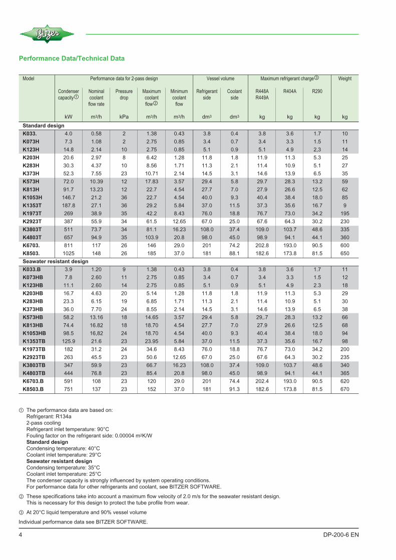
Model Performance data for 2-pass design Vessel volume Maximum refrigerant charge③ Weight
Condenser Nominal Pressure Maximum Minimum Refrigerant Coolant R448A R404A R290
capacity① coolant drop coolant coolant side side R449A
flow rate flow② flow
kW m3/h kPa m3/h m3/h dm3 dm3 kg kg kg kg
4 DP-200-6 EN
① The performance data are based on:
Refrigerant: R134a
2-pass cooling
Refrigerant inlet temperature: 90°C
Fouling factor on the refrigerant side: 0.00004 m2K/W
Standard design
Condensing temperature: 40°C
Coolant inlet temperature: 29°C
Seawater resistant design
Condensing temperature: 35°C
Coolant inlet temperature: 25°C
The condenser capacity is strongly influenced by system operating conditions.
For performance data for other refrigerants and coolant, see BITZER SOFTWARE.
② These specifications take into account a maximum flow velocity of 2.0 m/s for the seawater resistant design.
This is necessary for this design to protect the tube profile from wear.
③ At 20°C liquid temperature and 90% vessel volume
Individual performance data see BITZER SOFTWARE.
Performance Data/Technical Data
Standard design
K033. 4.0 0.58 2 1.38 0.43 3.8 0.4 3.8 3.6 1.7 10
K073H 7.3 1.08 2 2.75 0.85 3.4 0.7 3.4 3.3 1.5 11
K123H 14.8 2.14 10 2.75 0.85 5.1 0.9 5.1 4.9 2,3 14
K203H 20.6 2.97 8 6.42 1.28 11.8 1.8 11.9 11.3 5.3 25
K283H 30.3 4.37 10 8.56 1.71 11.3 2.1 11.4 10.9 5.1 27
K373H 52.3 7.55 23 10.71 2.14 14.5 3.1 14.6 13.9 6.5 35
K573H 72.0 10.39 12 17.83 3.57 29.4 5.8 29.7 28.3 13.2 59
K813H 91.7 13.23 12 22.7 4.54 27.7 7.0 27.9 26.6 12.5 62
K1053H 146.7 21.2 36 22.7 4.54 40.0 9.3 40.4 38.4 18.0 85
K1353T 187.8 27.1 36 29.2 5.84 37.0 11.5 37.3 35.6 16.7 9
K1973T 269 38.9 35 42.2 8.43 76.0 18.8 76.7 73.0 34.2 195
K2923T 387 55.9 34 61.5 12.65 67.0 25.0 67.6 64.3 30.2 230
K3803T 511 73.7 34 81.1 16.23 108.0 37.4 109.0 103.7 48.6 335
K4803T 657 94.9 35 103.9 20.8 98.0 45.0 98.9 94.1 44.1 360
K6703. 811 117 26 146 29.0 201 74.2 202.8 193.0 90.5 600
K8503. 1025 148 26 185 37.0 181 88.1 182.6 173.8 81.5 650
Seawater resistant design
K033.B 3.9 1.20 9 1.38 0.43 3.8 0.4 3.8 3.6 1.7 11
K073HB 7.8 2.60 11 2.75 0.85 3.4 0.7 3.4 3.3 1.5 12
K123HB 11.1 2.60 14 2.75 0.85 5.1 0.9 5.1 4.9 2.3 18
K203HB 16.7 4.63 20 5.14 1.28 11.8 1.8 11.9 11.3 5.3 29
K283HB 23.3 6.15 19 6.85 1.71 11.3 2.1 11.4 10.9 5.1 30
K373HB 36.0 7.70 24 8.55 2.14 14.5 3.1 14.6 13.9 6.5 38
K573HB 58.2 13.16 18 14.65 3.57 29.4 5.8 29,.7 28.3 13.2 66
K813HB 74.4 16.82 18 18.70 4.54 27.7 7.0 27.9 26.6 12.5 68
K1053HB 98.5 16,82 24 18.70 4.54 40.0 9.3 40.4 38.4 18.0 94
K1353TB 125.9 21.6 23 23.95 5.84 37.0 11.5 37.3 35.6 16.7 98
K1973TB 182 31.2 24 34.6 8.43 76.0 18.8 76.7 73.0 34.2 200
K2923TB 263 45.5 23 50.6 12.65 67.0 25.0 67.6 64.3 30.2 235
K3803TB 347 59.9 23 66.7 16.23 108.0 37.4 109.0 103.7 48.6 340
K4803TB 444 76.8 23 85.4 20.8 98.0 45.0 98.9 94.1 44.1 365
K6703.B 591 108 23 120 29.0 201 74.4 202.4 193.0 90.5 620
K8503.B 751 137 23 152 37.0 181 91.3 182.6 173.8 81.5 670

The BITZER SOFTWARE is available in many lan-
guages as a download for Windows as well as a web-
based version. It is compatible with any browser and is
always up to date. The program is also suitable for
tablets and smartphones.
The BITZER SOFTWARE covers:
// Performance data for all common refrigerants under
freely selectable operating conditions
// All relevant technical data
// Calculation results and individually designed perfor-
mance tables for condensers
// Accessories for the design of compound systems
// All relevant technical documents
// More BITZER products
bitzer-software.com
5DP-200-6 EN
Maximum allowable pressure
// Refrigerant side: 33 bar / -10 to 120°C
// Coolant side: 10 bar / -10 to 95°C
Temperatures below 4°C only with anti-freeze agent
These data apply to CE approval in accordance with
the EU Pressure Equipment Directive. They may devi-
ate depending on the approval scheme.
Approvals
Stationary applications
// CE: EU Pressure Equipment Directive 2014/68/EU
// EAC with Declaration of Conformity
// SELO ― China Manufacturing License
Marine applications
// Bureau Veritas
(BV Rules for the Classification of Steel Ships)
// DNV-GL
(GL Rules ― Ship Technology ― Seagoing Ships)
// Russian Maritime Register of Shipping (RS Rules for
the Classification and Construction of Sea-going Ships)
Influence of the fouling factor
The calculation of condenser performance in the
BITZER SOFTWARE does include a fouling factor.
The default value is representing clean fresh water.
For seawater cooling, please select an appropriate
fouling factor or alternatively select the condenser with
10% to 20% spare capacity.

For all common refrigerants and coolants
Permitted refrigerants
// R134a
// R22
// R290, R1270
// R1234yf
// R1234ze(E)
// R404A
// R507A
// R407C
// R448A
// R449A
// R450A
// R513A
Other refrigerants and refrigerant blends with tempera-
ture glide >2 K upon request.
Permitted coolants
// Industrial water
// Fresh water
// Process water
// Seawater
// Ethylene glycol/water
// Propylene glycol/water
// CaCl2 in water
// Tyxofit 1.15 in water
As a service, BITZER checks the suitability of the tube
materials on presentation of a water analysis. The
basis for the check is the current state of experience.
However, due to the complex conditions, an absolute
warranty of corrosion resistance cannot be given.
For corrosive coolants, select the seawater resistant
design.
Overdosing the anti-freeze agent can lead to increased
pressure drops and poorer heat transfer properties.
New refrigerants with low warming potential
All shell and tube condensers can be used with new
low greenhouse warming potential (GWP) refrigerants.
These refrigerants are important tools to reach the
emission reductions of the EU Regulation 517/2014
and similar scenarios clearly decided worldwide. Their
use is in line with our innovation targets.
The unsaturated fluorinated hydrocarbons (HFO)
R1234yf and R1234ze(E), two variants of tetrafluoro-
propene, play a central role in this. They can be used
as pure substances or as components of blends.
The pure substances R1234yf and R1234ze(E) are
classified as flammable in A2L according to ISO817.
All shell and tube condensers can be used with the
environmentally friendly refrigerants R290 propane
and R1270 propene.
For flammable refrigerants, the risk assessment for the
system has to be made reflecting the flammability and
it must be constructed in accordance with national or
local regulations. If the risk assessment classifies for
the installation area as an explosion protection zone,
the shell and tube condensers can not be used. Con-
sultation with BITZER is absolutely necessary.
Further information on these refrigerants can be found
in Refrigerant Report A-501.
6 DP-200-6 EN

Customised versions Discharge gas desuperheaters
Discharge gas desuperheaters increase system effi-
ciency. They lower the temperature of the refrigerant
discharged by the compressor, as shown in the figure
from A to B.
The amount of heat extracted can be used advanta-
geously in a heat recovery system, since it is present at
a higher temperature.
Discharge gas desuperheaters are always useful if the
discharge gas is too hot for the entire process. A dis-
charge gas desuperheater reduces the discharge gas
temperature.
In 2-stage refrigeration systems, for example, this
makes sense if the discharge gas in the low tempera-
ture stage is too hot to be efficiently compressed further
directly in the medium temperature stage.
Discharge gas desuperheaters increase the efficiency
of the medium temperature stage and at the same time
ensure sufficient motor cooling.
All BITZER shell and tube condensers with a second
refrigerant outlet downwards: K123HB .. K8503TB and
the special versions with 2nd refrigerant outlet of
K1053H .. K4803T can be used as discharge gas desu-
perheater.
Individual components of each shell and tube con-
denser can be delivered in customised positions if
necessary.
① Refrigerant inlet
② Refrigerant outlet
③ Additional refrigerant outlet according to model
④ Connection for the pressure relief valve
⑤ Lower fixing brackets
Matching accessories
// Fixing plates for compressors
// Fixing rails
// Adaptor for connecting the pressure relief valve
The additional refrigerant outlet is equipped with a sealing nut or blind
flange. Valve available as accessory ― see Price List.
* Special design
Model
K033NB
K073HB
K123HB
K203HB
K283HB
K373HB
K573HB
K813HB
K1053H*
K1053HB
K1353T*
K1353TB
K1973T*
K1973TB
K2923T*
K2923TB
K6703TB
K8503TB
K3803T*
K3803TB
K4803T*
K4803TB
– 11/4-12 UNF 13/4-12 UNF 21/4-12 UNF DN50 DN80DN80Additional
refrigerant outlet
Additional refrigerant outlet
7DP-200-6 EN
① ④
③⑤② ⑤

Standard design
Dimensional drawings
K033N
K033H
K073H
K123H
K203H
K283H
K373H
K573H
K813H
K1053H
K1353T
K1973T
K2923T
K3803T
K4803T
K6703.
K8503.
8 DP-200-6 EN
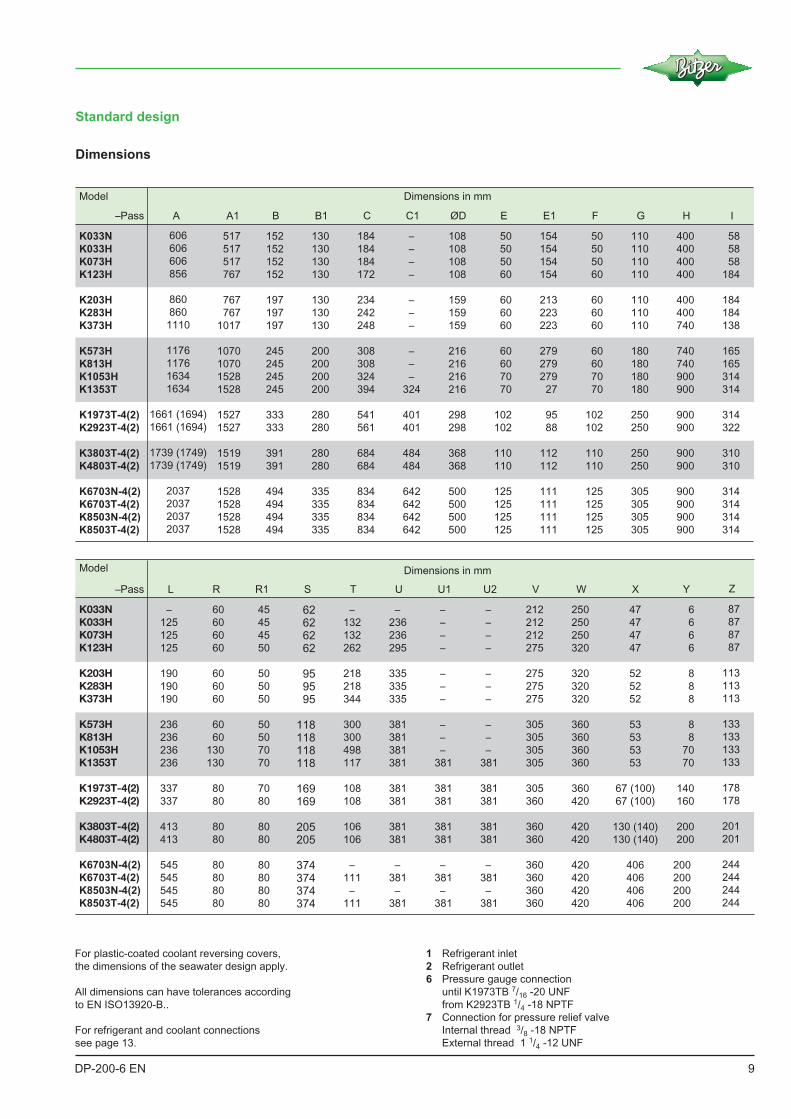
Standard design
For plastic-coated coolant reversing covers,
the dimensions of the seawater design apply.
All dimensions can have tolerances according
to EN ISO13920-B..
For refrigerant and coolant connections
see page 13.
1 Refrigerant inlet
2 Refrigerant outlet
6 Pressure gauge connection
until K1973TB 7/16 -20 UNF
from K2923TB 1/4 -18 NPTF
7 Connection for pressure relief valve
Internal thread 3/8 -18 NPTF
External thread 1 1/4 -12 UNF
Dimensions
Model Dimensions in mm
A A1
606
606
606
856
860
860
1110
1176
1176
1634
1634
1661 (1694)
1661 (1694)
1739 (1749)
1739 (1749)
2037
2037
2037
2037
517
517
517
767
767
767
1017
1070
1070
1528
1528
1527
1527
1519
1519
1528
1528
1528
1528
B
152
152
152
152
197
197
197
245
245
245
245
333
333
391
391
494
494
494
494
B1
130
130
130
130
130
130
130
200
200
200
200
280
280
280
280
335
335
335
335
C
184
184
184
172
234
242
248
308
308
324
394
541
561
684
684
834
834
834
834
C1
–
–
–
–
–
–
–
–
–
–
324
401
401
484
484
642
642
642
642
ØD
108
108
108
108
159
159
159
216
216
216
216
298
298
368
368
500
500
500
500
E
50
50
50
60
60
60
60
60
60
70
70
102
102
110
110
125
125
125
125
E1
154
154
154
154
213
223
223
279
279
279
27
95
88
112
112
111
111
111
111
F
50
50
50
60
60
60
60
60
60
70
70
102
102
110
110
125
125
125
125
G
110
110
110
110
110
110
110
180
180
180
180
250
250
250
250
305
305
305
305
H
400
400
400
400
400
400
740
740
740
900
900
900
900
900
900
900
900
900
900
I
58
58
58
184
184
184
138
165
165
314
314
314
322
310
310
314
314
314
314
K033N
K033H
K073H
K123H
K203H
K283H
K373H
K573H
K813H
K1053H
K1353T
K1973T-4(2)
K2923T-4(2)
K3803T-4(2)
K4803T-4(2)
K6703N-4(2)
K6703T-4(2)
K8503N-4(2)
K8503T-4(2)
Model Dimensions in mm
XL
–Pass
–Pass
47
47
47
47
52
52
52
53
53
53
53
67 (100)
67 (100)
130 (140)
130 (140)
406
406
406
406
–
125
125
125
190
190
190
236
236
236
236
337
337
413
413
545
545
545
545
R
60
60
60
60
60
60
60
60
60
130
130
80
80
80
80
80
80
80
80
R1
45
45
45
50
50
50
50
50
50
70
70
70
80
80
80
80
80
80
80
S
62626262
959595
118118118118
169169
205205
374374374374
T
–
132
132
262
218
218
344
300
300
498
117
108
108
106
106
–
111
–
111
U
–
236
236
295
335
335
335
381
381
381
381
381
381
381
381
–
381
–
381
U1
–
–
–
–
–
–
–
–
–
–
381
381
381
381
381
–
381
–
381
U2
–
–
–
–
–
–
–
–
–
–
381
381
381
381
381
–
381
–
381
V
212
212
212
275
275
275
275
305
305
305
305
305
360
360
360
360
360
360
360
W
250
250
250
320
320
320
320
360
360
360
360
360
420
420
420
420
420
420
420
Y
6
6
6
6
8
8
8
8
8
70
70
140
160
200
200
200
200
200
200
Z
87
87
87
87
113
113
113
133
133
133
133
178
178
201
201
244
244
244
244
K033NK033HK073HK123H
K203HK283HK373H
K573HK813HK1053HK1353T
K1973T-4(2)K2923T-4(2)
K3803T-4(2)K4803T-4(2)
K6703N-4(2)
K6703T-4(2)
K8503N-4(2)
K8503T-4(2)
9DP-200-6 EN

4 Pass
IN
OUT
G
B1
V
W
Z
B
C1
E1
L
S
C
F
R1 H/2
HIX
A1
A
6
Y
D
9
18
E
T U
62 7 12a
R
6
K033NB
K033HB
K073HB
K123HB
K203HB
K283HB
K373HB
K573HB
K813HB
K1053HB
K1353TB
K1973TB
K2923TB
K3803TB
K4803TB
K6703.B
K8503.B
10 DP-200-6 EN
Seawater resistant design
Dimensional drawings

11DP-200-6 EN
All dimensions can have tolerances according
to EN ISO13920-B.
For refrigerant and coolant connections
see page 13.
1 Refrigerant inlet
2 Refrigerant outlet
2a Additional refrigerant outlet
6 Pressure gauge connection
until K1973TB 7/16 -20 UNF
from K2923TB 1/4 -18 NPTF
7 Connection for pressure relief valve
Internal thread 3/8 -18 NPTF
External thread 1 1/4 -12 UNF
Model Dimensions in mm
A A1
626
626
626
876
882
882
1132
1210
1210
1668
1668
1687 (1690)
1687 (1690)
1739 (1745)
1739 (1745)
2037
2037
2037
2037
517
517
517
767
767
767
1017
1070
1070
1528
1528
1519
1519
1519
1519
1528
1528
1528
1528
B
152
152
152
152
197
197
197
245
245
245
245
333
333
391
391
494
494
494
494
B1
130
130
130
130
130
130
130
200
200
200
200
280
280
280
280
335
335
335
335
C
184
184
184
237
299
307
313
378
378
394
394
541
561
686
686
834
834
834
834
C1
–
–
–
172
234
242
248
308
308
324
324
401
401
486
486
642
642
642
642
ØD
108
108
108
108
159
159
159
216
216
216
216
298
298
368
368
500
500
500
500
E
50
50
50
60
60
60
60
60
60
70
70
102
102
110
110
125
125
125
125
E1
156
156
155
154
213
223
223
279
279
27
27
95
88
114
114
111
111
111
111
F
50
110
50
60
60
60
60
60
60
70
70
102
102
110
110
125
125
125
125
G
110
110
110
110
110
110
110
180
180
180
180
250
250
250
250
305
305
305
305
H
400
400
400
400
400
400
740
740
740
900
900
900
900
900
900
900
900
900
900
I
58
58
58
184
184
184
138
165
165
314
314
314
322
310
310
314
314
314
314
K033NB
K033HB
K073HB
K123HB
K203HB
K283HB
K373HB
K573HB
K813HB
K1053HB
K1353TB
K1973TB-4(2)
K2923TB-4(2)
K3803TB-4(2)
K4803TB-4(2)
K6703NB-4(2)
K6703TB-4(2)
K8503NB-4(2)
K8503TB-4(2)
Model Dimensions in mm
XL
67
67
67
67
73
73
73
76
76
76
76
100
100
130 (140)
130 (140)
406
406
406
406
–
125
125
125
190
190
190
236
236
236
236
337
337
413
413
545
545
545
545
R
60
60
60
60
60
60
60
60
60
130
130
80
80
80
80
80
80
80
80
R1
45
45
45
50
50
50
50
70
70
70
70
70
80
80
80
80
80
80
80
S
62,5
62,5
62,5
62,5
95
95
95
118
118
118
118
169
169
205
205
374
374
374
374
T
–
132
132
262
218
218
344
300
300
498
117
108
108
106
106
–
111
–
111
U
–
236
236
295
335
335
335
381
381
381
381
381
381
381
381
–
381
–
381
U1
–
–
–
–
–
–
–
–
–
–
381
381
381
381
381
–
381
–
381
U2
–
–
–
–
–
–
–
–
–
–
381
381
381
381
381
–
381
–
381
V
212
212
212
275
275
275
275
305
305
305
305
305
360
360
360
360
360
360
360
W
250
250
250
320
320
320
320
360
360
360
360
360
420
420
420
420
420
420
420
Y
6
6
6
65
65
65
65
70
70
70
70
140
160
200
200
200
200
200
200
Z
87
87
87
87
113
113
113
133
133
133
133
178
178
201
201
244
244
244
244
K033NB
K033HB
K073HB
K123HB
K203HB
K283HB
K373HB
K573HB
K813HB
K1053HB
K1353TB
K1973TB-4(2)
K2923TB-4(2)
K3803TB-4(2)
K4803TB-4(2)
K6703NB-4(2)
K6703TB-4(2)
K8503NB-4(2)
K8503TB-4(2)
Seawater resistant design
Dimensions
–Pass
–Pass

Coolant reversing covers
3a Coolant inlet 4-pass
3b Coolant inlet 2-pass
4a Coolant outlet 4-pass
4b Coolant outlet 2-pass
5 Coolant drain
G1/4 standard design (internal thread)
G1/2 seawater resistant design (internal thread)
6 Vent plug
12 DP-200-6 EN

Refrigerant and coolant connections
① For other connections see Price List
② Additional refrigerant outlet (bottom) for seawater resistant design from model K123HB ― see table on page 7.
③ Welding neck flanges DIN2633, ND 10/16 or threaded flanges DIN2566, ND 10/16
2-pass coolant connections 4-pass coolant connections
2
2
2
2
2
2
2
2
2
2
2
2
2
2
2
2
2 x G 1/22 x G 1/22 x G 1/2
2 x G 3/42 x G 3/42 x G 3/4
G 2
G 2
G 2
G 2
DN65③
DN65③
DN100③
DN100③
DN150
DN150
G 3/4G 3/4G 3/4
G 1
G 1
G 1
G 2
G 2
G 2
G 2
DN65③
DN65③
DN100③
DN100③
DN150
DN150
Inlet Outlet PassesPasses
All threads of the coolant connections are internal threads
Inlet Outlet
4
4
4
4
4
4
4
4
4
4
4
4
4
4
4
4
G 1/2G 1/2G 1/2
G 3/4G 3/4G 3/4
G 11/4G 11/4G 11/4G 11/4
G 2
G 2
DN80③
DN80③
DN125
DN125
G 1/2G 1/2G 1/2
G 3/4G 3/4G 3/4
G 11/4G 11/4G 11/4G 11/4
G 2
G 2
DN80③
DN80③
DN125
DN125
K033N(B) .. K373H(B): 4 or 2-pass, depending on connection
K573N(B) .. K8503.(B): different covers for 4- or 2-pass
K033N(B) .. K373H(B) K573N(B) .. K8503.(B)
2-pass 4-pass 2-pass 4-pass
13DP-200-6 EN
Model
K033.(B)
K073H(B)
K123H(B)
K203H(B)
K283H(B)
K373H(B)
K573H(B)
K813H(B)
K1053H(B)
K1353T(B)
K1973T(B)
K2923T(B)
K3803T(B)
K4803T(B)
K6703.(B)
K8503.(B)
Inlet ø
mm Zoll
Bushing①Refrigerant connections
Thread/FlangeOutletInlet Outlet ø②
mm Zoll
12
12
16
16
22
28
35
35
42
42
54
54
76
76
76
76
1-14 UNS
1-14 UNS
1-14 UNS
11/4-12 UNF
11/4-12 UNF
13/4-12 UN
13/4-12 UN
13/4-12 UN
21/4-12 UN
21/4-12 UN
DN50
DN50
DN80
DN80
DN100
DN100
10
10
12
16
22
22
28
28
35
35
42
54
76
76
76
76
1/21/25/8
5/87/8
11/8
13/813/815/815/8
21/821/8
31/831/8
31/831/8
3/83/81/2
5/87/87/8
11/811/813/813/8
15/821/8
31/831/8
31/831/8
3/4-16 UNF3/4-16 UNF
1-14 UNS
1-14 UNS
11/4-12 UNF
11/4-12 UNF
13/4-12 UN
13/4-12 UN
13/4-12 UN
13/4-12 UN
21/4-12 UN
DN50
DN80
DN80
DN100
DN100
Coolant connection positions on the
coolant reversing cover

Fixing rails
Rails
Model Bottom Top For compressors
Nr Nr Model
K033N(B) 327 301 01 – –
K073H(B) 327 301 01 327 301 12 2KES-05 .. 2FES-3
2KC-05.2 .. 2FC-3.2
K123H 327 301 04 327 301 20 2KES-05 .. 2FES-3
2KC-05.2 .. 2FC-3.2
327 301 21 2EES-2 .. 2CES-4
2EC-2.2 .. 2CC-4.2
K123HB S 327 301 20 2KES-05 .. 2FES-3
2KC-05.2 .. 2FC-3.2
327 301 21 2EES-2 .. 2CES-4
2EC-2.2 .. 2CC-4.2
K203H 327 301 04 327 301 21 2EES-2 .. 2CES-4
2EC-2.2 .. 2CC-4.2
327 301 22 4FES-3 .. 4BES-9
4FC-3.2 .. 4CC-9.2
327 301 24 4VES-6 .. 4NES-20
4VC(S)-6.2 .. 4NC(S)-20.2
K203HB S 327 301 21 2EES-2 .. 2CES-4
2EC-2.2 .. 2CC-4.2
327 301 22 4FES-3 .. 4BES-9
2EC-2.2 .. 2CC-4.2
327 301 24 4VES-6 .. 4NES-20
4VC(S)-6.2 .. 4NC(S)-20.2
K283H 327 301 04 327 301 21 2EES-2 .. 2CES-4
2EC-2.2 .. 2CC-4.2
327 301 22 4FES-3 .. 4BES-9
4FC-3.2 .. 4CC-9.2
327 301 24 4VES-6 .. 4NES-20
4VC(S)-6.2 .. 4NC(S)-20.2
K283HB S 327 301 21 2EES-2 .. 2CES-4
2EC-2.2 .. 2CC-4.2
327 301 22 4FES-3 .. 4BES-9
4FC-3.2 .. 4CC-9.2
327 301 24 4VES-6 .. 4NES-20
4VC(S)-6.2 .. 4NC(S)-20.2
K373H 327 301 04 327 301 21 2EES-2 .. 2CES-4
2EC-2.2 .. 2CC-4.2
327 301 22 4FES-3 .. 4BES-9
4FC-3.2 .. 4CC-9.2
327 301 24 4VES-6 .. 4NES-20
4VC(S)-6.2 .. 4NC(S)-20.2
K373HB S 327 301 21 2EES-2 .. 2CES-4
2EC-2.2 .. 2CC-4.2
327 301 22 4FES-3 .. 4BES-9
4FC-3.2 .. 4CC-9.2
327 301 24 4VES-6 .. 4NES-20
4VC(S)-6.2 .. 4NC(S)-20.2
K573H 327 301 05 327 301 24 4VES-6 .. 4NES-20
4VC(S)-6.2 .. 4NC(S)-20.2
327 301 10 4JE-13 .. 6FE-50
4J-13.2 .. 6F-50.2
K573HB S 327 301 24 4VES-6 .. 4NES-20
4VC(S)-6.2 .. 4NC(S)-20.2
327 301 10 4JE-13 .. 6FE-50
4J-13.2 .. 6F-50.2
Rails
Model Bottom Top For compressors
Nr. Nr. Model
K813H 327 301 05 327 301 24 4VES-6 .. 4NES-20
4VC(S)-6.2 .. 4NC(S)-20.2
327 301 10 4JE-13 .. 6FE-50
4J-13.2 .. 6F-50.2
K813HB S 327 301 24 4VES-6 .. 4NES-20
4VC(S)-6.2 .. 4NC(S)-20.2
327 301 10 4JE-13 .. 6FE-50
4J-13.2 .. 6F-50.2
K1053H 327 301 06 327 301 24 4VES-6 .. 4NES-20
4VC(S)-6.2 .. 4NC(S)-20.2
327 301 10 4JE-13 .. 6FE-50
4J-13.2 .. 6F-50.2
K1053HB S 327 301 24 4VES-6 .. 4NES-20
4VC(S)-6.2 .. 4NC(S)-20.2
327 301 10 4JE-13 .. 6FE-50
4J-13.2 .. 6F-50.2
K1353T(B) S 327 301 24 4VES-6 .. 4NES-20
4VC(S)-6.2 .. 4NC(S)-20.2
327 301 10 4JE-13 .. 6FE-50
4J-13.2 .. 6F-50.2
326 057 01 44JE-26 .. 66FE-100
44J-26.2 .. 66F-100.2
K1973T(B) S 327 301 24 4VES-6 .. 4NES-20
4VC(S)-6.2 .. 4NC(S)-20.2
327 301 10 4JE-13 .. 6FE-50
4J-13.2 .. 6F-50.2
326 057 01 44JE-26 .. 66FE-100
44J-26.2 .. 66F-100.2
K2923T(B) S 327 301 24 4VES-6 .. 4NES-20
4VC(S)-6.2 .. 4NC(S)-20.2
327 301 10 4JE-13 .. 6FE-50
4J-13.2 .. 6F-50.2
326 057 01 44JE-26 .. 66FE-100
44J-26.2 .. 66F-100.2
K3803T(B) S 327 301 24 4VES-6 .. 4NES-20
4VC(S)-6.2 .. 4NC(S)-20.2
327 301 10 4JE-13 .. 6FE-50
4J-13.2 .. 6F-50.2
326 057 01 44JE-26 .. 66FE-100
44J-26.2 .. 66F-100.2
K4803T(B) S 327 301 24 4VES-6 .. 4NES-20
4VC(S)-6.2 .. 4NC(S)-20.2
327 301 10 4JE-13 .. 6FE-50
4J-13.2 .. 6F-50.2
326 057 01 44JE-26 .. 66FE-100
44J-26.2 .. 66F-100.2
K6703N(B) S – –
K6703T(B) S 327 301 24 4VES-6 .. 4NES-20
4VC(S)-6.2 .. 4NC(S)-20.2
327 301 10 4JE-13 .. 6FE-50
4J-13.2 .. 6F-50.2
326 057 01 44JE-26 .. 66FE-100
44J-26.2 .. 66F-100.2
K8503N(B) S – –
K8503T(B) S 327 301 24 4VES-6 .. 4NES-20
4VC(S)-6.2 .. 4NC(S)-20.2
327 301 10 4JE-13 .. 6FE-50
4J-13.2 .. 6F-50.2
326 057 01 44JE-26 .. 66FE-100
44J-26.2 .. 66F-100.2
S = Standard
14 DP-200-6 EN

Fixing plates
For possible compressor/condenser combinations see page 14.
① Only with CE1/C1
15DP-200-6 EN

BITZER Kühlmaschinenbau GmbHEschenbrünnlestraße 15 // 71065 Sindelfingen // Germany
Tel +49 (0)70 31 932-0 // Fax +49 (0)70 31 932-147 [email protected] // www.bitzer.de
Subject to change // 80192301 // 09.2018