water cooled screw flooded chiller · flooded type screw chiller for example: qwcwf qwcwf1080a1-...
TRANSCRIPT
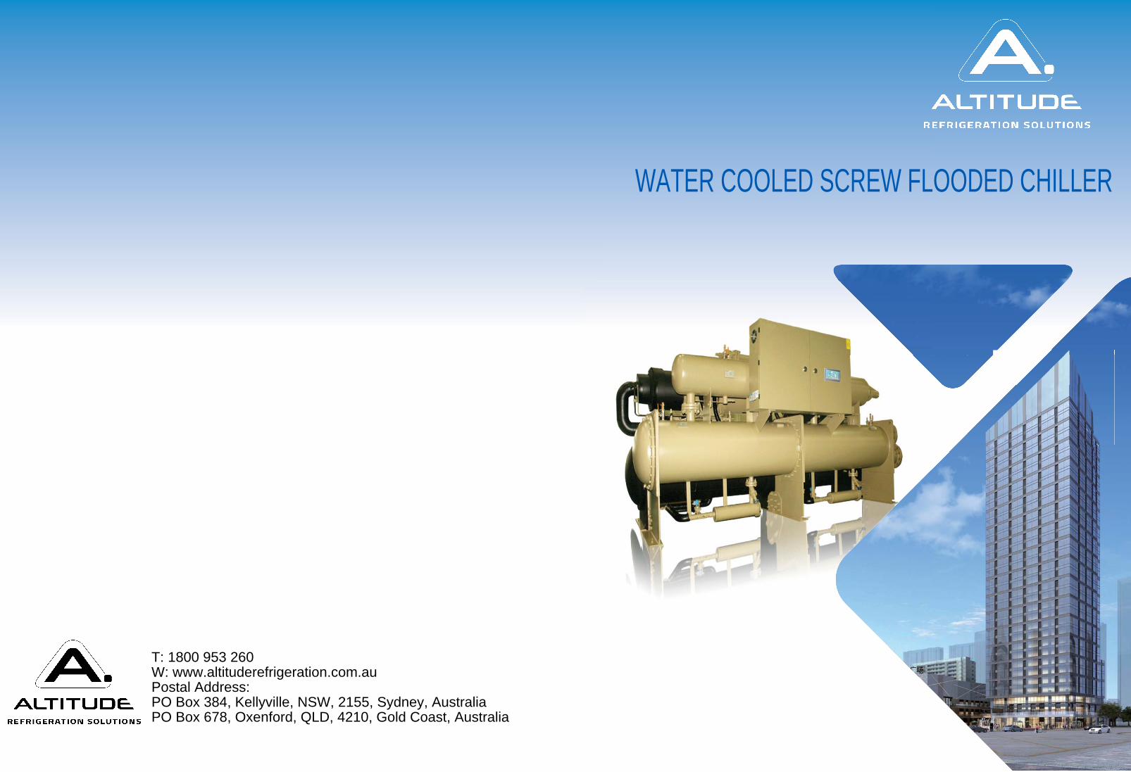
T: 1800 953 260W: www.altituderefrigeration.com.auPostal Address:PO Box 384, Kellyville, NSW, 2155, Sydney, AustraliaPO Box 678, Oxenford, QLD, 4210, Gold Coast, Australia
WATER COOLED SCREW FLOODED CHILLER

0201
1
2
2 410 A H O 1
02
02
03
05
07
09
11
13
15
17
19
23
25
27
28
29
30
31
32
33
34
35
36
37
Brief Introduction
Model Introduction
Product Features
R22 Basic unit Specification(single head)
R22 Basic unit Specification(twin heads)
R22 Heat recovery unit Specification(single head)
R22 Heat recovery unit Specification(twin heads)
R22 Energy Correction Table(single head)
R22 Energy Correction Table(twin heads)
R134a Specification(single head)
R134a Specification(twin heads)
R134a Energy Correction Table(single head)
R134a Energy Correction Table(twin heads)
R22 Dimension (Single head)
R22 Dimension(twin heads)
R134a Dimension (Single head)
R134a Dimension(twin heads)
Engine room requirement
Unit transportation and installation
Safety valve and discharge piping installation
Electrical wiring
Water system piping
Water quality management
Standard supply details
In today's increasingly shortage of energy in the world, we successfully launched a new generation of high-efficiency and high reliability flooded type water cooled screw chillers. The unit's full-load coefficient of performance (COP)reaches 5.7.This series of products is composed of electric power-driven screw compressors, high-efficiency heat exchangers, and advanced throttling mechanisms. The unit can not only provide the cold source for the central air-conditioning projects and industrial production, but also solve the problem of the supply of sanitary hot water according to the customer's requirements. It fully demonstrated the multi-functional features of the unit.The flooded type screw chiller has many advantages such as compact structure, environmental protection and energy saving, intelligent control, etc. the unit are widely used in hotels, restaurants, schools, theaters, shopping malls, office buildings, residential buildings, hospitals and other air-conditioned places, can also be used as cooling process for nuclear power, plastic chemicals, precision instruments and etc. with the improvement of international standards for building energy efficiency, the screw chiller will become even more popular.
Refrigerant: 1-R134a, omitted is R22
Compressor: 0-start up type, omitted is semi-hermetical type
Function: omitted is basic type, H-heat recovery type
Deign version
Unit no.
Compressor amount
Flooded type screw chiller
For example:
QWCWF
QWCWF1080A1- Unit no.is 080, design version A, refrigerant is R134a, single compressor flooded type screw chillerQWCWF2410BH- Unit no.is 410, design version B, refrigerant is R22, double compressors flooded type screw chiller with heat recovery function.
PRODUCT OVERVIEW
MODELSPECIFICATION
CONTENT
WATER-COOLED SCREW FLOODED CHILLER

0403
HIGH EFFICIENCY AND ENERGY SAVING1
3
RELIABLE QUALITY2
EASY INSTALLATION3
INTELLIGENT CONTROL4
The use of water –cooled flooded type high efficiency screw compressor, the most advanced tooth design, high-precision processing technology, high volumetric efficiency; apply internationally famous brands fluorine-resistant motor, under various conditions are in the best efficiency.
High efficient flooded evaporator design make total heat transfer coefficient is three times of a dry type evaporator. The unit's energy efficiency ratio can be increased by 12%. The chilled water flows inside of the tube, the scale is easy to clean, the evaporating tube has a dense ring-shaped slit to form the vaporization core and strengthen the heat transfer efficiency on the outside of the tube. Enhancing inner side of the pipe heat transfer ribs to increase water side perturbation and turbulent heat exchange, which can delay scaling
Efficient condenser design, narrow sharp and high tooth, fine processing, thin liquid film, large heat transfer area, better spoiler effect.
The compressor has stepless control, the capacity of the unit changes according to loading to ensure a stable outlet water temperature. At the same time, the unit energy consumption is reduced, the partial load energy efficiency is increased by 15%
Waste heat and total heat recovery technology, the unit generates domestic hot water by absorbing condensing heat under cooling mode, without any energy consumption and emissions pollution, heat recovery can improve the unit’s operating conditions, improve operating efficiency and reduce unit operating costs.
We have special equipment manufacturing qualifications and excellent manufacturing equipments.
The patent-designed full-year cooling differential pressure valve(optional) ensures the unit's annual reliable cooling operation.
Patented design of"oil control system":built-in high-efficiency oil separator. Oil supply with pressure difference, no oil pump. Unique concentrated ejection of oil return ensures that the surface of the heat exchange tube is free of oil film thermal resistance, improve the heat exchange efficiency, and an efficient secondary oil separator combined with external machinery to ensure the efficient oil separation.
Compressor
Oil separator
Condenser
Evaporator
Maximum 8 units can be grouped control to simplify operation management and reduce the risk of misoperation.Automatically record operating parameters and fault SMS function, the factory provides professional technical services at any time.
Advanced Siemens PLC microcomputer controllerUser-friendly operation interface, beautiful interface, easy operation: users only need to switch machine, mode selection, water temperature setting can complete the unit operation:Stepless energy control, water temperature control accuracy up to ±0.5°C, to ensure indoor comfort;The advanced remote central monitoring system(optional) can realize multiple unit group control, simplify operation management, judge air conditioning load automatically, and optimize system operation efficiency;
Perfect control system protection: the compressor adopts multiple protections to completely prevent the rotor from jamming or motor overheating and burning. The real-time monitoring and control of high and low pressure, exhaust temperature, operating current, and in/out water temperature can ensure the safe operation of the unit. Multi-channel protection such as water flow, antifreeze, low pressure and water temperature monitoring completely avoids the possibility of frost cracking in the evaporator tube.
The pipe connection can be changed freely according to customer requirements, starter cabinets along with the unit can save the clients’ extra expense; refrigerants and lubricating oils has been filled before delivery; only needs to connect the water pipe and power supply at site; unit components are flexible connected and they are easy to disassemble and installation.
The special features are: the unit is neatly arrange, compact and small in size, beautiful appearance and exquisite structure.
PRODUCT FEATURES
WATER-COOLED SCREW FLOODED CHILLER
0605
4
193 222 260 294 324
1450
2050
1650
2250
1450
2200 2200 2250
16501550
353 380 400
1600
2300
1700
2500
1700
2500
0
5
Cooling capacity
Power input
Rated current
Power type
Energy control
Com
pressor
Type
Start type
Qty
Oil heater
Evaporator
Type
Water flow
Pressure drop
Pipe
Condenser
Type
Water flow
Pressure drop
Pipe
Refrigerant
Type
Charge
Size
Length
Width
Height
Weight
Weight
Operation weight
Semi-hermetical screw type
Flooded type high efficiency
Shell and tube type
Cooling capacity
Power input
Rated current
Power type
Energy control
Com
pressor
Type
Start type
Qty
Oil heater
Evaporator
Type
Water flow
Pressure drop
Pipe
Condenser
Type
Water flow
Pressure drop
Pipe
Refrigerant
Type
ChargeS
izeLength
Width
Height
Weight
Weight
Operation weight
Semi-hermetical screw type
Flooded type high efficiency
Shell and tube type
Model QWCWFModel QWCWF
Chilled water Cooling water
Cooling working condition
Operation range
Water inlet Water outlet
Water outlet Water inlet and outlet difference
Water inlet Water outlet
Water inlet Water inlet and outlet difference
Chilled water Cooling water
Cooling working condition
Operation range
Water inlet Water outlet
Water outlet Water inlet and outlet difference
Water inlet Water outlet
Water inletWater inlet and outlet difference
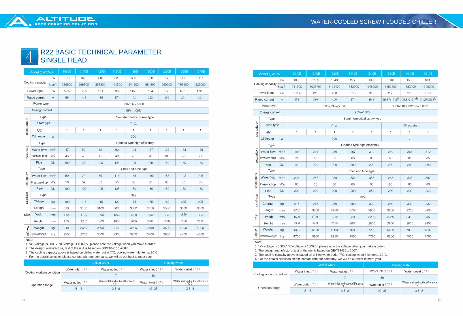
Note:1, “a”- voltage is 6000V, “b”-voltage is 10000V, please note the voltage when you make a order;2, The design, manufacture, test of the unit is based on GB/T18430.1-2007;3, The cooling capacity above is based on chilled water outlet 7°C, cooling water inlet temp. 30°C;4, For the details selection please contact with our company, we will do our best to meet your
Note:1, “a”- voltage is 6000V, “b”-voltage is 10000V, please note the voltage when you make a order;2, The design, manufacture, test of the unit is based on GB/T18430.1-2007;3, The cooling capacity above is based on chilled water outlet 7°C, cooling water inlet temp. 30°C;4, For the details selection please contact with our company, we will do our best to meet your
Direct start
R22 BASIC TECHNICAL PARAMETERSINGLE HEAD
WATER-COOLED SCREW FLOODED CHILLER
0807
5
1850 1850 1850 1850 1850 2100 2100
21502200 2200 2300 2300 2300
1800
96+96 118+118 138+138 138+177 171+171 177+177 193+193 222+222 222+260 222+260 260+260 294+294 294+324
25502100 2100 2100 2100
294+324 353+353 353+380 400+400 406+487 471+471 471+541 541+541(2X25.8)a
/(2x15.3)b(25.8+29.8)a
/(15.3+17.7)b(2X29.8)a
/(2x17.7)b(2X34.2)a
/(2x20.3)b(29.8+34.2)a
/(17.7+20.3)b
Cooling capacity
Power input
Rated current
Power type
Energy control
Com
pressor
Type
Start type
Qty
Oil heater
Evaporator
Type
Water flow
Pressure drop
Pipe
Condenser
Type
Water flow
Pressure drop
Pipe
Refrigerant
Type
Charge
Size
Length
Width
Height
Weight
Weight
Operation weight
Semi-hermetical screw type
Flooded type high efficiency
Shell and tube type
Cooling capacity
Power input
Rated current
Power type
Energy control
Com
pressor
Type
Start type
Qty
Oil heater
Evaporator
Type
Water flow
Pressure drop
Pipe
Condenser
Type
Water flow
Pressure drop
Pipe
Refrigerant
Type
ChargeS
ize
Length
Width
Height
Weight
Weight Operation weight
Semi-hermetical screw type
Flooded type high efficiency
Shell and tube type
Model QWCWF Model QWCWF
Chilled water Cooling water
Cooling working condition
Operation range
Water inlet Water outlet
Water outlet Water inlet and outlet difference
Water inlet Water outlet
Water inletWater inlet and outlet difference
Chilled water Cooling water
Cooling working condition
Operation range
Water inlet Water outlet
Water outlet Water inlet and outlet difference
Water inlet Water outlet
Water inlet Water inlet and outlet difference
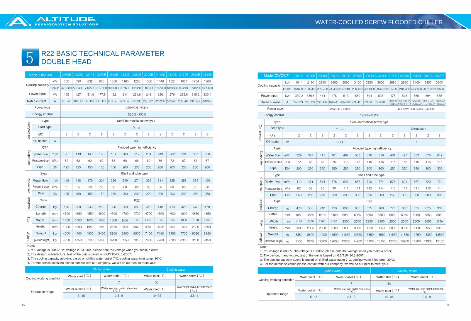
Note:1, “a”- voltage is 6000V, “b”-voltage is 10000V, please note the voltage when you make a order;2, The design, manufacture, test of the unit is based on GB/T18430.1-2007;3, The cooling capacity above is based on chilled water outlet 7°C, cooling water inlet temp. 30°C;4, For the details selection please contact with our company, we will do our best to meet your
Note:1, “a”- voltage is 6000V, “b”-voltage is 10000V, please note the voltage when you make a order;2, The design, manufacture, test of the unit is based on GB/T18430.1-2007;3, The cooling capacity above is based on chilled water outlet 7°C, cooling water inlet temp. 30°C;4, For the details selection please contact with our company, we will do our best to meet your
Direct start
R22 BASIC TECHNICAL PARAMETERDOUBLE HEAD
WATER-COOLED SCREW FLOODED CHILLER
09 10
6
193 222 260 294 324 353 380 400
Cooling capacity
Power input
Rated currentPower type
Energy control
Com
pressor
Type
Start type
Qty
Oil heater
Evaporator
Type
Water flow
Pressure drop
Pipe
Condenser
Type
Water flow
Pressure drop
Pipe
Refrigerant
Type
Charge
Size
Length
Width
Height
Weight
Weight Operation weight
Semi-hermetical screw type
Flooded type high efficiency
Shell and tube type
Cooling capacity
Power input
Rated current
Power type
Energy control
Com
pressor
Type
Start type
Qty
Oil heater
Evaporator
Type
Water flowPressure drop
Pipe
Condenser
Type
Water flow
Pressure drop
Pipe
RefrigerantType
ChargeS
ize
Length
Width
Height
Weight
Weight
Operation weight
Semi-hermetical screw type
Flooded type high efficiency
Shell and tube type
Model QWCWF Model QWCWF
Chilled water Cooling water
Cooling working condition
Operation range
Water inlet Water outlet
Water outlet Water inlet and outlet difference
Water inlet Water outlet
Water inletWater inlet and outlet difference
Chilled water Cooling water
Cooling working condition
Operation range
Water inlet Water outlet
Water outlet Water inlet and outlet difference
Water inlet Water outlet
Water inletWater inlet and outlet difference
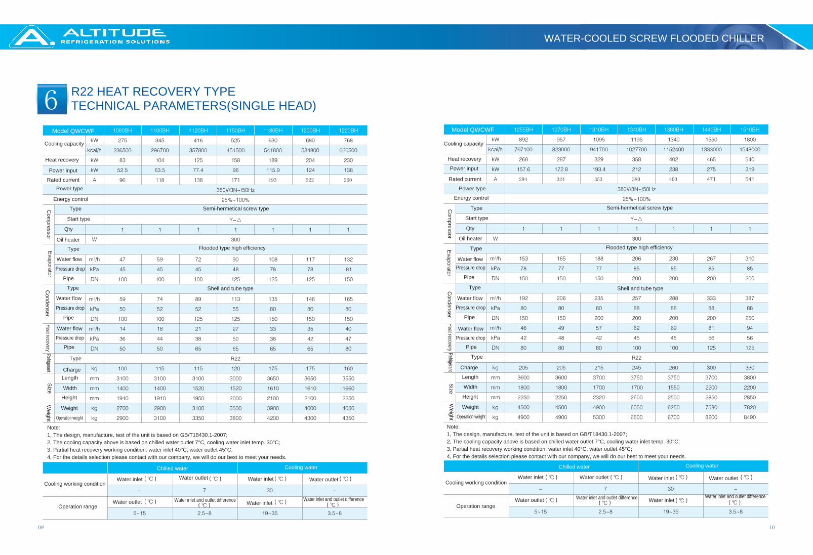
Note:1, The design, manufacture, test of the unit is based on GB/T18430.1-2007;2, The cooling capacity above is based on chilled water outlet 7°C, cooling water inlet temp. 30°C;3, Partial heat recovery working condition: water inlet 40°C, water outlet 45°C;4, For the details selection please contact with our company, we will do our best to meet your needs.
Note:1, The design, manufacture, test of the unit is based on GB/T18430.1-2007;2, The cooling capacity above is based on chilled water outlet 7°C, cooling water inlet temp. 30°C;3, Partial heat recovery working condition: water inlet 40°C, water outlet 45°C;4, For the details selection please contact with our company, we will do our best to meet your needs.
Heat recovery
Heat recovery
Water flow
Pressure drop
Pipe
Heat recovery
Heat recovery
Water flow
Pressure drop
Pipe
R22 HEAT RECOVERY TYPETECHNICAL PARAMETERS(SINGLE HEAD)
WATER-COOLED SCREW FLOODED CHILLER

11 12
7
96+96 118+118 138+138 138+177 171+171 177+177 193+193 222+222 222+260 222+260 260+260
2200 2200
294+294 294+324 294+324 353+353 353+380 400+400 406+487 471+471 471+541 541+541
Cooling capacity
Power input
Rated current
Power type
Energy control
Com
pressor
Type
Start type
Qty
Oil heater
Evaporator
Type
Water flow
Pressure drop
Pipe
Condenser
Type
Water flowPressure drop
Pipe
Refrigerant
Type
Charge
Size
Length
WidthHeight
Weight
WeightOperation weight
Semi-hermetical screw type
Flooded type high efficiency
Shell and tube type
Cooling capacity
Power input
Rated current
Power type
Energy control
Com
pressor
Type
Start type
Qty
Oil heater
Evaporator
Type
Water flowPressure drop
Pipe
Condenser
Type
Water flowPressure drop
Pipe
RefrigerantType
ChargeS
ize
Length
Width
Height
Weight
Weight
Operation weight
Semi-hermetical screw type
Flooded type high efficiency
Shell and tube type
Model QWCWFModel QWCWF
Note:1, The design, manufacture, test of the unit is based on GB/T18430.1-2007;2, The cooling capacity above is based on chilled water outlet 7°C, cooling water inlet temp. 30°C;3, Partial heat recovery working condition: water inlet 40°C, water outlet 45°C;4, For the details selection please contact with our company, we will do our best to meet your needs.
Note:1, The design, manufacture, test of the unit is based on GB/T18430.1-2007;2, The cooling capacity above is based on chilled water outlet 7°C, cooling water inlet temp. 30°C;3, Partial heat recovery working condition: water inlet 40°C, water outlet 45°C;4, For the details selection please contact with our company, we will do our best to meet your needs.
Heat recoveryHeat recovery
Heat recovery
Water flow
Pressure drop
Pipe
Heat recovery
Water flow
Pressure drop
Pipe
Chilled water Cooling water Chilled water Cooling water
Cooling working condition
Operation range
Water inlet
Water outlet
Water outlet
Water inlet and outlet difference
Water inlet Water outlet
Water inletWater inlet and outlet difference
Cooling working condition
Operation range
Water inlet Water outlet
Water outlet Water inlet and outlet difference
Water inlet Water outlet
Water inlet Water inlet and outlet difference
R22 HEAT RECOVERY TYPETECHNICAL PARAMETERS(DOUBLE HEAD)
WATER-COOLED SCREW FLOODED CHILLER

1413
8
318
312
305
298
401
392
384
376
482
472
461
451
610
598
585
572
730
716
700
685
790
772
755
738
890
872
853
832
253.5
1030
1009
986
965
1102
1080
1056
1033
1264
1239
1211
1185
1382
1354
1324
1295
1550
1520
1485
1452
1795
1763
1720
1683
2088
2047
2000
1960
Model
QWCWF
CoolingWater Inlet temp.
Cooling capacity Power input
Chilled water outlet temp. Chilled water outlet temp. ModelQWCWF
CoolingWater Inlet temp.
Cooling capacity Power input
Chilled water outlet temp. Chilled water outlet temp.
R22 ENERGY CORRECTION SINGLE HEAD
WATER-COOLED SCREW FLOODED CHILLER

1615
9
636
624
610
598
802
784
768
752
964
944
922
902
1111
1080
1055
1033
1220
1196
1170
1144
1345
1318
1289
1261
1460
1432
1400
1370
1580
1552
1510
1476
1675
1640
1604
1570
1765
1730
1690
1654
1917
1879
1837
1797
321.3
545.7
2060
2018
1992
1930
2152
2109
2062
2017
2206
2163
2115
2068
2531
2481
2425
2372
2765
2711
2650
2592
3110
3040
2972
2907
3346
3280
3206
3137
3592
3521
3443
3368
3880
3803
3718
3637
4173
4090
4000
3912
Model
QWCWF
CoolingWater Inlet temp.
Cooling capacity Power input
Chilled water outlet temp. Chilled water outlet temp. Model
QWCWF
CoolingWater Inlet temp.
Cooling capacity Power input
Chilled water outlet temp. Chilled water outlet temp.
R22 ENERGY CORRECTION DOUBLE HEAD
WATER-COOLED SCREW FLOODED CHILLER
1817
10
m3/h
m3/h
m3/h
m3/h
Note:1, “a”- voltage is 6000V, “b”-voltage is 10000V, please note the voltage when you make a order;2, The design, manufacture, test of the unit is based on GB/T18430.1-2007;3, The cooling capacity above is based on chilled water outlet 7°C, cooling water inlet temp. 30°C;4, For the details selection please contact with our company, we will do our best to meet your
Note:1, “a”- voltage is 6000V, “b”-voltage is 10000V, please note the voltage when you make a order;2, The design, manufacture, test of the unit is based on GB/T18430.1-2007;3, The cooling capacity above is based on chilled water outlet 7°C, cooling water inlet temp. 30°C;4, For the details selection please contact with our company, we will do our best to meet your
Chilled water Cooling water
Cooling working condition
Operation range
Water inlet Water outlet
Water outlet Water inlet and outlet difference
Water inlet Water outlet
Water inlet Water inlet and outlet difference
Chilled water Cooling water
Cooling working condition
Operation range
Water inlet Water outlet
Water outlet Water inlet and outlet difference
Water inlet Water outlet
Water inlet Water inlet and outlet difference
Cooling capacity
Power input
Rated current
Power type
Energy control
Com
pressor
Type
Start type
Qty
Oil heater
Evaporator
Type
Water flow
Pressure drop
Pipe
Condenser
Type
Water flow
Pressure drop
Pipe
Refrigerant
Type
Charge
Size
Length
Width
Height
Weight
Transport
Operation
Semi-hermetical screw type
Flooded type high efficiency
Shell and tube type
Cooling capacity
Power input
Rated current
Power type
Energy control
Com
pressor
Type
Start type
Qty
Oil heater
Evaporator
Type
Water flow
Pressure drop
Pipe
Condenser
Type
Water flow
Pressure drop
Pipe
Refrigerant
Type
ChargeS
izeLength
Width
Height
Weight
Transport
Operation
Semi-hermetical screw type
Flooded type high efficiency
Shell and tube type
Direct start up
Model QWCWF Model QWCWF
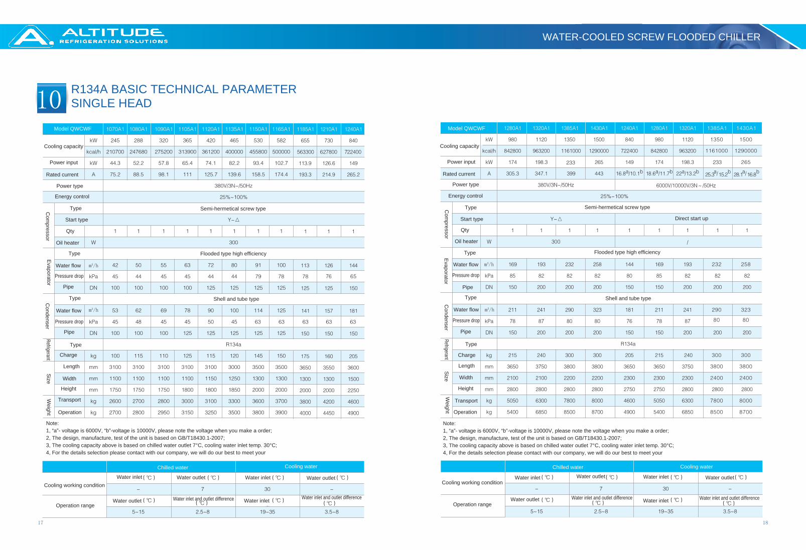
R134A BASIC TECHNICAL PARAMETER SINGLE HEAD
WATER-COOLED SCREW FLOODED CHILLER

2019
11
Note:1, “a”- voltage is 6000V, “b”-voltage is 10000V, please note the voltage when you make a order;2, The design, manufacture, test of the unit is based on GB/T18430.1-2007;3, The cooling capacity above is based on chilled water outlet 7°C, cooling water inlet temp. 30°C;4, For the details selection please contact with our company, we will do our best to meet your
Note:1, “a”- voltage is 6000V, “b”-voltage is 10000V, please note the voltage when you make a order;2, The design, manufacture, test of the unit is based on GB/T18430.1-2007;3, The cooling capacity above is based on chilled water outlet 7°C, cooling water inlet temp. 30°C;4, For the details selection please contact with our company, we will do our best to meet your
Chilled water Cooling water
Cooling working condition
Operation range
Water inlet Water outlet
Water outletWater inlet and outlet difference
Water inlet Water outlet
Water inlet Water inlet and outlet difference
Chilled water Cooling water
Cooling working condition
Operation range
Water inlet Water outlet
Water outlet Water inlet and outlet difference
Water inlet Water outlet
Water inlet Water inlet and outlet difference
Cooling capacity
Power input
Rated current
Power type
Energy control
Com
pressor
Type
Start type
Qty
Oil heater
Evaporator
Type
Water flow
Pressure drop
Pipe
Condenser
Type
Water flow
Pressure drop
Pipe
Refrigerant
Type
Charge
Size
Length
Width
Height
Weight
Transport
Operation
Semi-hermetical screw type
Flooded type high efficiency
Shell and tube type
Cooling capacity
Power input
Rated current
Power type
Energy control
Com
pressor
Type
Start type
Qty
Oil heater
Evaporator
Type
Water flow
Pressure drop
Pipe
Condenser
Type
Water flow
Pressure drop
Pipe
Refrigerant
Type
ChargeS
izeLength
Width
Height
Weight
Transport
Operation
Semi-hermetical screw type
Flooded type high efficiency
Shell and tube type
Model QWCWF Model QWCWF
R134A BASIC TECHNICAL PARAMETER DOUBLE HEAD
WATER-COOLED SCREW FLOODED CHILLER

21 22
11
m3/h
m3/h
m3/h
m3/h
Note:1, “a”- voltage is 6000V, “b”-voltage is 10000V, please note the voltage when you make a order;2, The design, manufacture, test of the unit is based on GB/T18430.1-2007;3, The cooling capacity above is based on chilled water outlet 7°C, cooling water inlet temp. 30°C;4, For the details selection please contact with our company, we will do our best to meet your
Note:1, “a”- voltage is 6000V, “b”-voltage is 10000V, please note the voltage when you make a order;2, The design, manufacture, test of the unit is based on GB/T18430.1-2007;3, The cooling capacity above is based on chilled water outlet 7°C, cooling water inlet temp. 30°C;4, For the details selection please contact with our company, we will do our best to meet your
Chilled water Cooling water
Cooling working condition
Operation range
Water inlet Water outlet
Water outlet Water inlet and outlet difference
Water inlet Water outlet
Water inlet Water inlet and outlet difference
Chilled water Cooling water
Cooling working condition
Operation range
Water inlet Water outlet
Water outlet Water inlet and outlet difference
Water inlet Water outlet
Water inlet Water inlet and outlet difference
Cooling capacity
Power input
Rated current
Power type
Energy control
Com
pressor
Type
Start type
Qty
Oil heater
Evaporator
Type
Water flow
Pressure drop
Pipe
Condenser
Type
Water flow
Pressure drop
Pipe
Refrigerant
Type
Charge
Size
Length
Width
Height
Weight
Transport
Operation
Semi-hermetical screw type
Flooded type high efficiency
Shell and tube type
Cooling capacity
Power input
Rated current
Power type
Energy control
Com
pressor
Type
Start type
Qty
Oil heater
Evaporator
Type
Water flow
Pressure drop
Pipe
Condenser
Type
Water flow
Pressure drop
Pipe
Refrigerant
Type
ChargeS
ize
Length
Width
Height
Weight
Transport
Operation
Semi-hermetical screw type
Flooded type high efficiency
Shell and tube type
Model QWCWF
Direct start up Direct start up
Model QWCWF
R134A BASIC TECHNICAL PARAMETER DOUBLE HEAD
WATER-COOLED SCREW FLOODED CHILLER

23 24
12Model
QWCWF
CoolingWater Inlet temp.
Cooling capacity Power input
Chilled water outlet temp. Chilled water outlet temp. ModelQWCWF
CoolingWater Inlet temp.
Cooling capacity Power input
Chilled water outlet temp. Chilled water outlet temp.
R134A BASIC ENERGY CORRECTION
WATER-COOLED SCREW FLOODED CHILLER

2625
13ModelQWCWF
CoolingWater
Inlet temp.
Cooling capacity Power inputChilled water outlet temp.Chilled water outlet temp. Model
QWCWF
CoolingWater
Inlet temp.
Cooling capacity Power inputChilled water outlet temp.Chilled water outlet temp.
R134A BASIC ENERGY CORRECTION
WATER-COOLED SCREW FLOODED CHILLER
2827
14
1080B
1100B
1120B
1150B
1180B
1200B
1220B
1255B
1270B
1310B
1340B
1380B
1440B
1510B
A
3100
3100
3100
3000
3650
3650
3550
3600
3600
3700
3750
3750
3700
3800
3750
3750
3800
B
1120
1120
1260
1260
1450
1450
1550
1650
1650
1600
1700
1700
2200
2200
2350
2350
2350
C
1700
1700
1800
1850
2050
2200
2200
2250
2250
2300
2500
2500
2850
2850
2800
2850
2850
D
125
125
125
125
135
135
140
155
155
155
175
175
195
195
175
195
195
E
2580
2580
2580
2580
3080
3080
3080
3080
3080
3080
3080
3080
3080
3080
3080
3080
3080
F
150
150
150
150
150
150
150
200
200
260
230
250
523
523
423
383
383
G
820
820
900
900
950
950
1000
1150
1150
1080
1160
1160
1460
1460
1240
1320
1320
H
466
466
466
466
496
496
496
531
531
531
531
571
611
611
571
611
611
I
586
586
597
599
636.5
636.5
639
639
639
671.5
722.5
722.5
740
745
722.5
740
745
J
185
185
215
260
245
245
300
300
300
305
305
305
350
340
305
350
340
K
225
225
240
270
270
270
300
300
300
345
345
345
758
758
618
618
618
L
495
495
560
530
530
530
550
752.5
728
707.5
737.5
715
747.5
747.5
635
607.5
607.5
M
260
260
260
260
300
300
300
305
305
305
305
350
405
405
350
405
405
DN100
DN100
DN100
DN125
DN125
DN125
DN150
DN150
DN150
DN150
DN200
DN200
DN200
DN200
DN200
DN200
DN200
DN100
DN100
DN125
DN125
DN150
DN150
DN150
DN150
DN150
DN200
DN200
DN200
DN200
DN200
DN200
DN200
DN200
15
172 1400
1550
1550
701.5 647.5
Service distance Service distance
Service distance
Cooling water inlet
Cooling water outlet
Chilled water inlet
Chilled water outlet
Control cabinet
Secondary oil separator
Condenser
Evaporator
Service distance Service distance
ModelQWCWF
Size mm Pipe and size
Evaporator Condenser
ModelQWCWF
Size mm Pipe and sizeEvaporator Condenser
1380B(high)
1440B(high)
1510B(high)
Note:"high"means voltage is 6000V OR10000V Note:"high"means voltage is 6000V OR10000V
high
high
high
high
high
Service distance
Service distance Service distance
Cooling water inlet
Cooling water outlet
Chilled water inlet
Chilled water outlet
Control cabinet
Secondary oil separator
Condenser
Evaporator
Service distanceService distance
Secondary oil separator
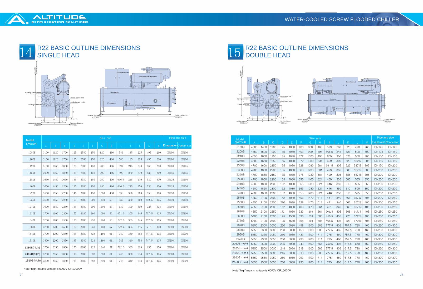
R22 BASIC OUTLINE DIMENSIONSSINGLE HEAD
R22 BASIC OUTLINE DIMENSIONSDOUBLE HEAD
WATER-COOLED SCREW FLOODED CHILLER

3029
16 17
Ser
vice
dis
tanc
e
Service distanceService distance
Cooling water inlet
Cooling water outlet
Chilled water inlet
Chilled water outlet
Control cabinet
Secondary oil separator
Condenser
Evaporator
Service distanceService distance
Service distance
Service distance
Service distance
Cooling water inlet
Cooling water outletChilled water inlet
Chilled water outlet
Control cabinet
Secondary oil separator
Condenser
Evaporator
Service distance Service distance
Secondary oil separator
ModelQWCWF
Size mm Pipe and size
Evaporator CondenserModel
QWCWFSize mm Pipe and size
Evaporator Condenser
Note:"high"means voltage is 6000V OR10000V
high
high
high
high
high
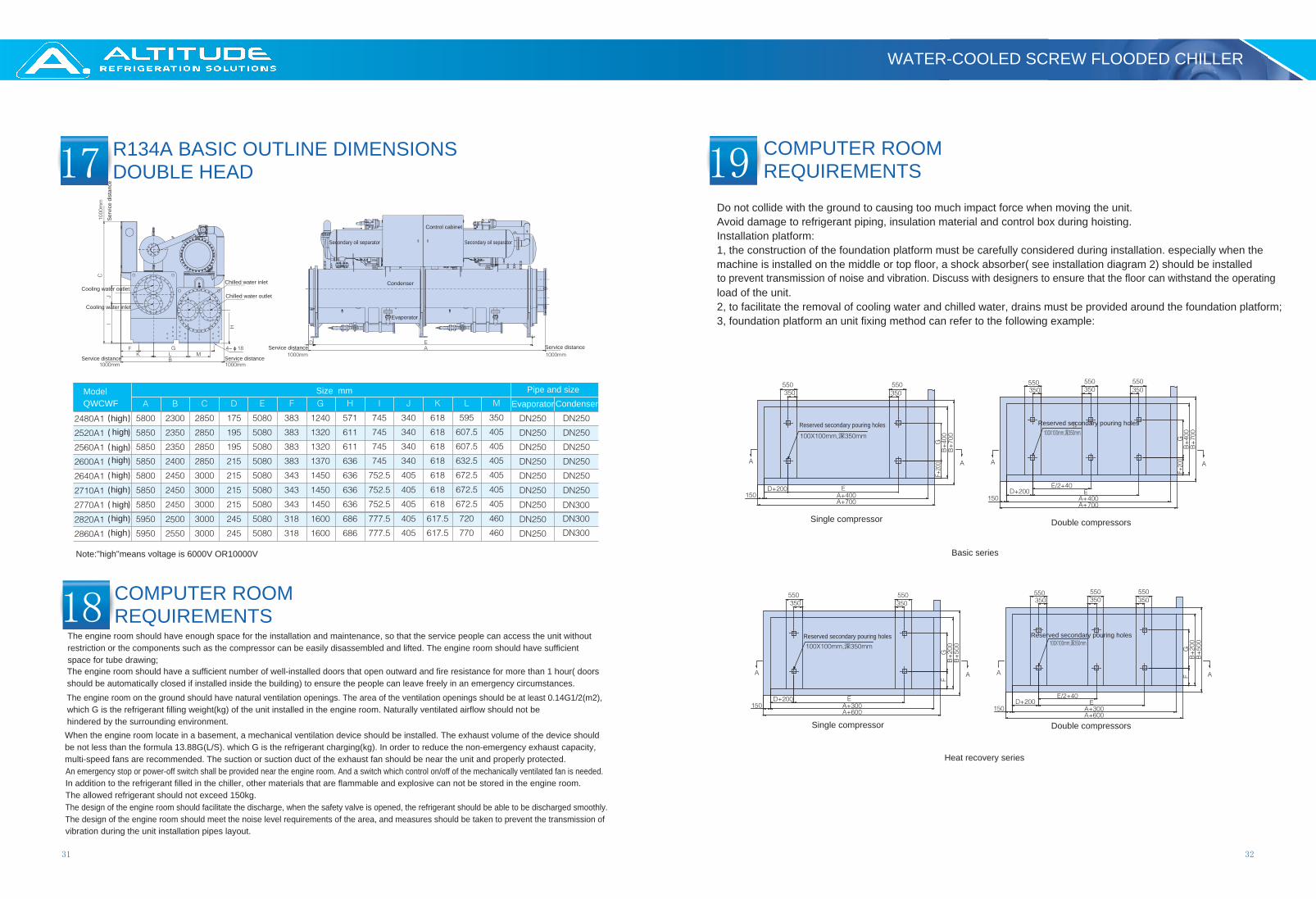
R134A BASIC OUTLINE DIMENSIONSSINGLE HEAD
R134A BASIC OUTLINE DIMENSIONSDOUBLE HEAD
WATER-COOLED SCREW FLOODED CHILLER
31 32
17
18
19
Service distance
Ser
vice
dis
tanc
e
Service distance
Cooling water inlet
Cooling water outletChilled water inlet
Chilled water outlet
Control cabinet
Secondary oil separator
Condenser
Evaporator
Service distance
Service distance
ModelQWCWF
Size mm Pipe and sizeEvaporator Condenser
Secondary oil separator
Note:"high"means voltage is 6000V OR10000V
highhigh
highhigh
highhigh
highhighhigh
The engine room should have enough space for the installation and maintenance, so that the service people can access the unit without restriction or the components such as the compressor can be easily disassembled and lifted. The engine room should have sufficient space for tube drawing;The engine room should have a sufficient number of well-installed doors that open outward and fire resistance for more than 1 hour( doors should be automatically closed if installed inside the building) to ensure the people can leave freely in an emergency circumstances.The engine room on the ground should have natural ventilation openings. The area of the ventilation openings should be at least 0.14G1/2(m2), which G is the refrigerant filling weight(kg) of the unit installed in the engine room. Naturally ventilated airflow should not be hindered by the surrounding environment.When the engine room locate in a basement, a mechanical ventilation device should be installed. The exhaust volume of the device should be not less than the formula 13.88G(L/S). which G is the refrigerant charging(kg). In order to reduce the non-emergency exhaust capacity, multi-speed fans are recommended. The suction or suction duct of the exhaust fan should be near the unit and properly protected.An emergency stop or power-off switch shall be provided near the engine room. And a switch which control on/off of the mechanically ventilated fan is needed.In addition to the refrigerant filled in the chiller, other materials that are flammable and explosive can not be stored in the engine room. The allowed refrigerant should not exceed 150kg.The design of the engine room should facilitate the discharge, when the safety valve is opened, the refrigerant should be able to be discharged smoothly.The design of the engine room should meet the noise level requirements of the area, and measures should be taken to prevent the transmission of vibration during the unit installation pipes layout.
Do not collide with the ground to causing too much impact force when moving the unit.Avoid damage to refrigerant piping, insulation material and control box during hoisting.Installation platform:1, the construction of the foundation platform must be carefully considered during installation. especially when the machine is installed on the middle or top floor, a shock absorber( see installation diagram 2) should be installed to prevent transmission of noise and vibration. Discuss with designers to ensure that the floor can withstand the operating load of the unit.2, to facilitate the removal of cooling water and chilled water, drains must be provided around the foundation platform;3, foundation platform an unit fixing method can refer to the following example:
Reserved secondary pouring holes
Reserved secondary pouring holes
Reserved secondary pouring holes
Reserved secondary pouring holes
Basic series
Heat recovery series
Single compressor Double compressors
Single compressor Double compressors
COMPUTER ROOMREQUIREMENTS
R134A BASIC OUTLINE DIMENSIONSDOUBLE HEAD
COMPUTER ROOMREQUIREMENTS
WATER-COOLED SCREW FLOODED CHILLER

33 34
19
20
●
●
●
●●
21Anchor bolt
Gasket
Cushion plate
Foundation
Unit foot pedestal
Nuts
Shock absorbers
Unit foot pedestal
Nuts
Shock absorbers
Mounting holes
Installation diagram1 Installation diagram 2
Note:1, foundation need reinforced concrete structure;2, please consider the maintenance space of the unit when setting up the foundation;3, basic drainage ditch should be more than or equal to 0.5%, and the angle tens to drain;4, when the foundation needs to be set on the floor, communicate with the architectural designer and set it up on the load-bearing structure;5, the basic drawing is for reference only, please combine the actual construction conditions when making the specific drawings.
The size of the inner diameter of the discharge pipe should be able to meet the safety discharge rate requirements of the container;Drainage pipes should be provided with discharge pipes;The discharge pipe outside the engine room should be able to prevent the entry of rainwater and should be kept away from the air intake of the engine room. There must be no obstacle within one meter of the gas discharge port;If multiple units are installed at the same time, each unit must install its own discharge pipe;The refrigerant is heavier than air, to prevent accidental suffocation, do not vent the refrigerant into the air in the engine room.
Safety valve
Corrugated pipe
Angle valveO
utside engine roomInside engine room
Galvanized steel pipe
1, The power voltage must be stable during the operation. Taking all voltage drop factors into consideration. The unit operating voltage must be maintained within ±10% of the rated value. If the voltage is too high or too low, it will damage the unit.
2, The phase-to-phase voltage difference should not exceed ±2% of the rated value, and the difference between the highest and lowest phase current is less than 3% of the rated value to avoid overheating the compressor.
3, The power frequency should be kept within ±2% of the rated value.4, The minimum starting voltage of the unit must be maintained at more than 85% of the rated value.5, If the power cord is too long, the compressor can’ be started. Therefore, the length of the power cord must
ensure that the voltage difference between the beginning and the tail of the cords voltage is less than rated value of 2% during operation. If the length cannot be shortened, the power cord must be thickened,
6, The wirings must be constructed in strict accordance with the electrical code and regulations, and good insulation. After the unit is connected, the insulation between the terminal and the unit should be measured with a 500V high resistance meter, and the insulation resistance is not less than 5M Ohm.
7, In order to protect the human safety, and avoid a danger of electric shock from leakage of the unit, the unit's casing should have a good an reliable grounding protection device to prevent electric shock accidents. So it should be strictly constructed according to electrical regulations.
8, The wiring uses a three-phase five-wire system and only copper conductors are allowed.9, All field wiring and component installation must be operated by licensed electrician.10, Grounding of the unit must company with local regulations.11, Don't mix low voltage(<30V) and high voltage(> 30 V) control wires in the same wire tube.12, Wire connection must be firm, otherwise it may cause overheating, electric shock or fire etc, but it must not
be too hard on the terminal. Wrap the wire and do not loosen the protective layer and other related parts.13, In order to reduce the hazards of transformers, wiring and other electrical equipment in the event of a short-
circuit accident on the line, and to facilitate the independent control of the start-up and shutdown of each compressor. Each unit's power supply wire must be equipped with a property-capacity no-fuse breaker(NFB) and a separate set of power inlets. Its dynamic wiring is shown in the following diagram. The capacity is selected based on 1.8 times of the rated current value.
14, All compressor adopt star -delta starting (optional soft starter can be selected according to customer requirements)15, The main unit should be equipped with an independent transformer, which rated capacity is calculated
according to the total power input's 1.6-1.8times
n: compressor qty
Userside
ELECTRICAL WIRING
COMPUTER ROOMREQUIREMENTS
INSTALLATION OFFLOW SWITCH
WATER-COOLED SCREW FLOODED CHILLER
22INSTALLATION INSTRUCTIONS FOR CHILLED WATER AND COOLING WATER SYSTEM1
35 36
●
●
●
●
●
HOT WATER SYSTEM INSTALLATION INSTRUCTIONS2
23●
●
●
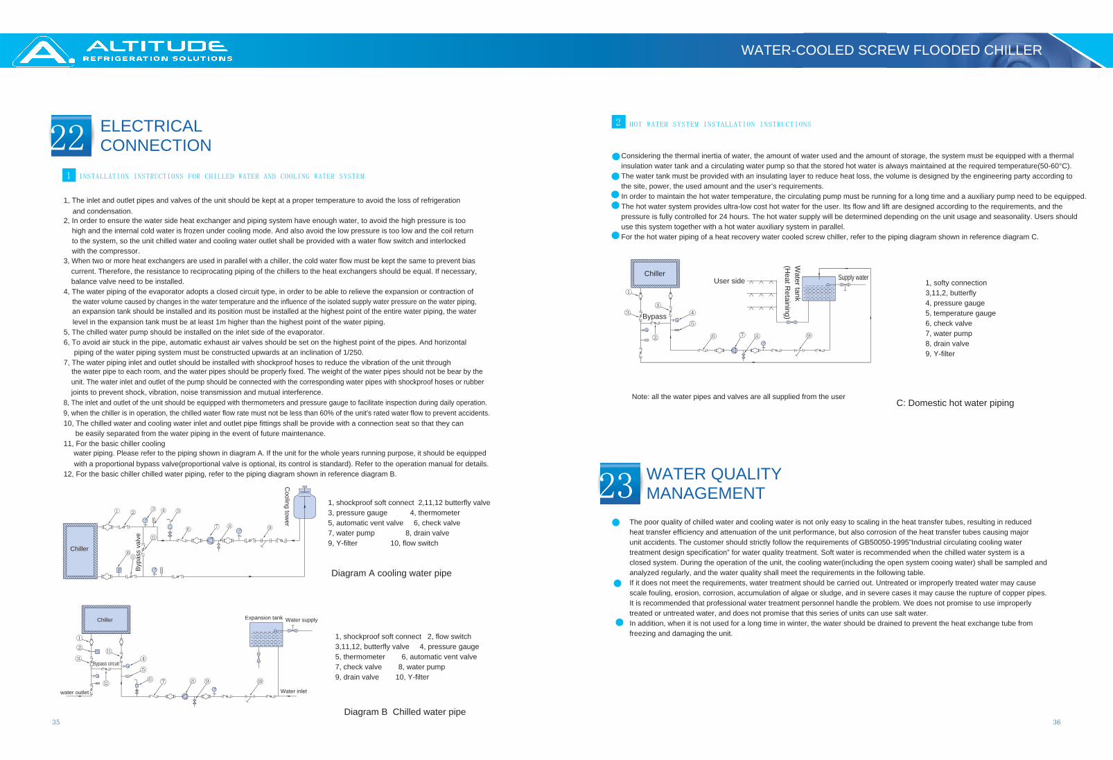
Considering the thermal inertia of water, the amount of water used and the amount of storage, the system must be equipped with a thermal insulation water tank and a circulating water pump so that the stored hot water is always maintained at the required temperature(50-60°C).The water tank must be provided with an insulating layer to reduce heat loss, the volume is designed by the engineering party according to the site, power, the used amount and the user’s requirements.In order to maintain the hot water temperature, the circulating pump must be running for a long time and a auxiliary pump need to be equipped.The hot water system provides ultra-low cost hot water for the user. Its flow and lift are designed according to the requirements, and the pressure is fully controlled for 24 hours. The hot water supply will be determined depending on the unit usage and seasonality. Users should use this system together with a hot water auxiliary system in parallel.For the hot water piping of a heat recovery water cooled screw chiller, refer to the piping diagram shown in reference diagram C.
The poor quality of chilled water and cooling water is not only easy to scaling in the heat transfer tubes, resulting in reduced heat transfer efficiency and attenuation of the unit performance, but also corrosion of the heat transfer tubes causing major unit accidents. The customer should strictly follow the requirements of GB50050-1995”Industrial circulating cooling water treatment design specification” for water quality treatment. Soft water is recommended when the chilled water system is a closed system. During the operation of the unit, the cooling water(including the open system cooing water) shall be sampled and analyzed regularly, and the water quality shall meet the requirements in the following table.If it does not meet the requirements, water treatment should be carried out. Untreated or improperly treated water may cause scale fouling, erosion, corrosion, accumulation of algae or sludge, and in severe cases it may cause the rupture of copper pipes. It is recommended that professional water treatment personnel handle the problem. We does not promise to use improperly treated or untreated water, and does not promise that this series of units can use salt water.In addition, when it is not used for a long time in winter, the water should be drained to prevent the heat exchange tube from freezing and damaging the unit.
Chiller
Bypass
User side
Water tank
(Heat R
etaining)
Supply water
Note: all the water pipes and valves are all supplied from the user
1, softy connection3,11,2, butterfly4, pressure gauge5, temperature gauge6, check valve7, water pump8, drain valve9, Y-filter
C: Domestic hot water piping
1, The inlet and outlet pipes and valves of the unit should be kept at a proper temperature to avoid the loss of refrigeration and condensation.
2, In order to ensure the water side heat exchanger and piping system have enough water, to avoid the high pressure is too high and the internal cold water is frozen under cooling mode. And also avoid the low pressure is too low and the coil return to the system, so the unit chilled water and cooling water outlet shall be provided with a water flow switch and interlocked with the compressor.
3, When two or more heat exchangers are used in parallel with a chiller, the cold water flow must be kept the same to prevent bias current. Therefore, the resistance to reciprocating piping of the chillers to the heat exchangers should be equal. If necessary, balance valve need to be installed.
4, The water piping of the evaporator adopts a closed circuit type, in order to be able to relieve the expansion or contraction of the water volume caused by changes in the water temperature and the influence of the isolated supply water pressure on the water piping, an expansion tank should be installed and its position must be installed at the highest point of the entire water piping, the water level in the expansion tank must be at least 1m higher than the highest point of the water piping.
5, The chilled water pump should be installed on the inlet side of the evaporator.6, To avoid air stuck in the pipe, automatic exhaust air valves should be set on the highest point of the pipes. And horizontal
piping of the water piping system must be constructed upwards at an inclination of 1/250.7, The water piping inlet and outlet should be installed with shockproof hoses to reduce the vibration of the unit through
the water pipe to each room, and the water pipes should be properly fixed. The weight of the water pipes should not be bear by the unit. The water inlet and outlet of the pump should be connected with the corresponding water pipes with shockproof hoses or rubber joints to prevent shock, vibration, noise transmission and mutual interference.
8, The inlet and outlet of the unit should be equipped with thermometers and pressure gauge to facilitate inspection during daily operation.9, when the chiller is in operation, the chilled water flow rate must not be less than 60% of the unit's rated water flow to prevent accidents.10, The chilled water and cooling water inlet and outlet pipe fittings shall be provide with a connection seat so that they can
be easily separated from the water piping in the event of future maintenance.11, For the basic chiller cooling
water piping. Please refer to the piping shown in diagram A. If the unit for the whole years running purpose, it should be equipped with a proportional bypass valve(proportional valve is optional, its control is standard). Refer to the operation manual for details.
12, For the basic chiller chilled water piping, refer to the piping diagram shown in reference diagram B.
Diagram A cooling water pipe
Diagram B Chilled water pipe
Chiller Expansion tank
Water inlet
Water supply
Bypass circuit
water outlet
1, shockproof soft connect 2, flow switch3,11,12, butterfly valve 4, pressure gauge5, thermometer 6, automatic vent valve7, check valve 8, water pump9, drain valve 10, Y-filter
Chiller
Cooling tow
er
Byp
ass
valv
e
1, shockproof soft connect 2,11,12 butterfly valve3, pressure gauge 4, thermometer5, automatic vent valve 6, check valve7, water pump 8, drain valve9, Y-filter 10, flow switch
WATER QUALITYMANAGEMENT
ELECTRICAL CONNECTION
WATER-COOLED SCREW FLOODED CHILLER

23
37 38
24STANDARD PERFORMANCE PARAMETERS1
STANDARD DELIVERY INSTRUCTIONS2
SPARE PARTS LIST3
If the customer needs, we can provide spare parts as follows: refrigeration oil, dry ball, oil filter, refrigerant
At the time of delivery, the compressors, evaporators, condensers, control cabinets, startup cabinets, throttling valves, and other refrigeration accessories and piping accessories have been assembled as a complete unit;When the unit are delivered, the factory has completed testing; The charging of refrigerant and refrigeration oil has been completed before delivery, and with the water flow switch;We can supply rubber anti-vibration pacts according to the needs of users.
The standard design working condition: chilled water outlet temp.7°C, cooling water inlet temp.30°C; evaporator waterside fouling factor is 0.44(m2.°C/kw), condenser waterside fouling factor is 0.088(m2.°C/kw), refrigerant is R22 or R134a. If you have any other special requirements, please contact with us.
Basic item
sR
eference item
PH valueConductivity
Chloride ionSulfate ion
Acid consumption
Full hardnessIron
Sulfide ion
Ammonium ionsSilica
no found no found
Item Unit Supplemental water Cooling(chilled) water Corrosion Scaling
WATER QUALITY MANAGEMENT
STANDARD SUPPLYDETAILS
WATER-COOLED SCREW FLOODED CHILLER