water and sewer utility standards manual€¦ · water and sewer utility standards manual table of...
TRANSCRIPT

WATER and SEWER UTILITY STANDARDS MANUAL


PRINCE WILLIAM COUNTY SERVICE AUTHORITY
WATER AND SEWER UTILITY STANDARDS
MANUAL
This manual represents the water and sewer system standards as approved by the Board of Directors of the Prince William County Service Authority (Service Authority) on April 14, 1994, amended October 10, 1996 and further amended October 09, 2008. As such, these standards must be used for all service areas under the jurisdiction of the Service Authority. The Service Authority Water and Sewer Utility Standards Manual (PWCSA-USM) is designed to fully supplement Sections 400 and 500 of the Prince William County Design and Construction Manual (DCSM). Comments and inquiries are to be directed to the Service Authority.
APPROVED: ________________________________________________________________
General Manager DATE: _____________________________________________________________________

Prince William County Service Authority Utility Standards Manual
i
PRINCE WILLIAM COUNTY SERVICE AUTHORITY
WATER AND SEWER UTILITY STANDARDS MANUAL
TABLE OF CONTENTS
GENERAL CONDITIONS Page 101.01 Purpose and Authorization 100-1
101.02 Definitions and Abbreviations 100-2 101.03 Local Review Authority 100-3
101.04 Review Process 100-4 101.05 Information Required on Project Plans 100-4 101.06 Variances 100-4 101.07 Easements 100-5 101.08 Applicable References 100-6 101.09 Corrections of Deficiencies Noted During the 100-6
Inspection Process 101.10 Beneficial Use 100-7
101.11 As-Built Plans and Bond Release 100-8 101.12 Chesapeake Bay Preservation 100-8 101.13 Additional Information 100-9 WATER SUPPLY SYSTEMS 110 – GENERAL REQUIREMENTS 110.01 General 100-9 110.02 Hydraulic Analysis Parameters and Reporting 100-10 110.03 Public Water Service Connections 100-15 110.04 Private Water Service Connections 100-16 110.05 Large Meter Installations 100-16 110.06 Water-Only Accounts 100-16 110.07 Sub-meters 100-17 110.08 Valve Boxes 100-17 110.09 Cross Connections 100-18
Prince William County Service Authority Utility Standards Manual
ii
120 – DESIGN PARAMETERS 120.01 Line Sizes 100-18
120.02 Depth of Cover 100-18 120.03 Thrust Restraint 100-19
120.04 Valve Locations 100-19 120.05 Separation of Water Mains and Sanitary Sewers 100-19 120.06 Blow-offs 100-21 120.07 Air Release 100-21 120.08 Termination of Water Mains 100-21 120.09 Valve, Air Release, Meter and Blow-off Chambers 100-22 120.10 Fire Hydrant Locations 100-22 120.11 Surface Water Crossing 100-23 120.12 Fire Lines 100-24 130 – DESIGN STANDARDS – PIPE AND FITTINGS 130.01 Water Pipe, Fittings and Accessories 100-24 130.02 Casings and Tunnels 100-25 130.03 Gate Valves 100-26 130.04 Butterfly Valves 100-26 130.05 Valve Boxes 100-26 130.06 Fire Hydrants 100-27 130.07 Air Release Valves 100-28 130.08 Tapping Valves and Sleeves 100-28 140 – WATER LINE CONSTRUCTION 140.01 General 100-28 140.02 Blasting 100-30 140.03 Excavation and Bedding and Backfill 100-30 140.04 Installation of Pipe and Fittings 100-31 140.05 Fire Hydrant Installation 100-32 140.06 Testing 100-33 140.07 Wet Taps 100-34 140.08 Disinfection of Water Mains 100-34
Prince William County Service Authority Utility Standards Manual
iii
SANITARY SEWER SYSTEMS 150 – GENERAL REQUIREMENTS 150.01 General 100-35 150.02 Private Sewer Service 100-35 150.03 Relationship to Waterworks Structures 100-35 150.04 Location of Sewers in Relation to Streams, 100-35 Estuaries, Lakes and Reservoirs 150.05 Sewer–Only Accounts 100-36 150.06 Grease Traps 100-36 150.07 Inverted Siphons 100-36 160 – DESIGN PARAMETERS 160.01 Tributary Population 100-36 160.02 Design Quantities 100-37 160.03 Hydraulic Design Criteria 100-38 160.04 Separation of Water Mains and Sanitary Sewers 100-40 160.05 Manholes 100-43 160.06 Water Tightness 100-44 160.07 Service Connections 100-44 160.08 Depth of Cover 100-45 160.09 Slope 100-46 170 – DESIGN STANDARDS – SANITARY SEWERS 170.01 Pipe Materials for Sanitary Sewers 100-46 170.02 Manholes 100-48 170.03 Casings and Tunnels 100-49 170.04 Anchors 100-49 170.05 Sewer Service Connections 100-49 180 – DESIGN STANDARDS – LIFT STATIONS 180.01 General Requirements 100-50 180.02 Design Criteria 100-51 180.03 Force Mains 100-61 180.04 Grinder Pumps 100-61

Prince William County Service Authority Utility Standards Manual
iv
190 – SANITARY SEWER CONSTRUCTION 190.01 General Requirements 100-62 190.02 Excavation 100-63 190.03 Backfill 100-64 190.04 Pipe Installation 100-64 190.05 Service Connections 100-65 190.06 Manholes 100-65 190.07 Pipe Connections at Manholes 100-66 190.08 Acceptance Tests 100-67 190.09 Force Main Testing 100-74 190.10 Protection of Existing Improvements 100-74 190.11 Bypass Pumping Requirements 100-74

Prince William County Service Authority Utility Standards Manual
v
TABLES AND FIGURES ABBREVIATIONS 100-2 FIGURE 1-1 Peak Flow Factors 100-37 TABLE Page 1-1 Easement Widths 100- 6 1-2 Average Daily Water Demand Factors 100-12 1-3 Allowable Leakage Per 1,000 Feet of Pipeline 100-34 1-4 Average Daily Wastewater Flows 100-38 1-5 Minimum Slopes 100-39 1-6 Maximum Depth of Cover 100-45 1-7 Anchor Spacing 100-49 1-8 Maximum Trench Width 100-63 1-9 Minimum Specified Time Required for a 0.5 psi Pressure 100-71 Drop for Size and Length of Pipe Indicated 1-10 Minimum Specified Time Required for a 1.0-inch Vacuum 100-72 Drop for Height and Diameter of Manholes Shown

Prince William County Service Authority Utility Standards Manual
vi
WATER DISTRIBUTION SYSTEM DETAILS
Detail No. Detail Title
W01.07.00 5/8” x 3/4”Residential Meter
W02.07.00 1” Residential Meter With Fire Service Detail (Only)
W03.07.00 5/8” x 3/4” Meter in 2” Copper Setter for Commercial Use (Only)
W04.07.00 1 1/2” and 2” Residential Fire Service Detail
W05.07.00 1” Meter in 2” Copper Setter for Commercial Use (Only)
W06.07.00 1 1/2” Meter in 2” Copper Service Water Distribution System
W07.07.00 1 1/2” and 2” Meter in D.I.P. Service Water Distribution System
W08.07.00 3” or 4” Master Meter Vault
W09.07.00 6” 8”, or 10” Main Line Meter Vault
W10.07.00 5/8” x 3/4” and 1” Water Meter and Monitor Frame and Cover Detail
W11.07.00 3/4” Water Service Connection Detail
W12.07.00 4” D.I.P. Service Connection Detail
W13.07.00 Blow-Off Assembly
W14.07.00 Typical Valve and Valve Box
W15.07.00 Water Distribution System Air Release Valve
W16.07.00 Joint Restraint Device
W17.07.00 Buttresses for 22 1/2” Horizontal Bend
W18.07.00 Buttresses for 45° Horizontal Bend
W19.07.00 Buttresses for 90° Horizontal Bend

Prince William County Service Authority Utility Standards Manual
vii
WATER DISTRIBUTION SYSTEM DETAILS
Detail No. Detail Title
W20.07.00 Buttresses for Tees, Plugs, & Caps
W21.07.00 Buttress for 11 1/4°, 22 1/2° and 45° Lower Vertical Bends
W22.07.00 Anchorage for 11 1/4°, 22 1/2° and 45° Upper Vertical Bends
W23.07.00 Dead End Anchor Detail
W24.07.00 Typical Fire Hydrant
W25.07.00 Typical Fire Hydrant Location with Curb and Gutter or Ditch Line
W26.07.00 Typical Fire Hydrant Location in Island and Parking Area
W27.07.00 Typical Fire Hydrant Location on Residential Street
W28.08.00 Typical Fire Hydrant Post Protection
W29.07.00 Tapping Sleeve and Valve Detail
W30.07.00 5/8” x 3/4” and 1” Sub-Meter Detail
W31.07.00 Lowering Water Main or New Installation

Prince William County Service Authority Utility Standards Manual
viii
SEWER DISTRIBUTION SYSTEM DETAILS
Detail No. Detail Title
S01.07.00 Sewer Service Connection Plan View
S02.07.00 Sewer Service Connection Profile
S03.07.00 Cleanout Cover For Paved Areas
S04.07.00 Grinder Pump Connection to Gravity Sewer Main
S05.07.00 Insert – A – Tee
S06.07.00 Precast Concrete 4’ Diameter Manhole
S07.07.00 Precast Concrete 5’ and 6’ Diameter Manhole
S08.07.00 Precast Concrete Cut – In Manhole
S09.07.00 Construction of Manhole Over Existing Sewer
S10.07.00 Abandonment of Manhole
S11.07.00 Precast Concrete Manhole Cone Section
S12.07.00 Precast Concrete Manhole Adjustment Ring
S13.07.00 Standard Manhole Frame and Cover
S14.07.00 Watertight Manhole Frame and Cover
S15.07.00 Internal Manhole Chimney Seal
S16.07.00 External Manhole Chimney Seal
S17.07.00 Waterproof Manhole Insert
S18.07.00 Precast Concrete Manhole Flat Top
S19.07.00 Precast Concrete Manhole Reducer

Prince William County Service Authority Utility Standards Manual
ix
SEWER DISTRIBUTION SYSTEM DETAILS
Detail No. Detail Title
S20.07.00 Precast Concrete Manhole Conical Reducer – 5’ to 4’
S21.07.00 Inside Drop Manhole Detail
S22.07.00 4’ Manhole with Outside Drop Connection
S23.07.00 Manhole Vent
S24.07.00 Flushing Station and Grinder Pump Connection to Low Pressure Force Main
S25.07.00 Sewage Force Main Air or Vacuum Release Assembly
S26.07.00 Grease Trap
S27.07.00 Concrete Cradle and Encasement
S28.08.00 Steel Casing
S29.07.00 Clay Dam Detail
S30.07.00 PWCSA Logo

Prince William County Service Authority Utility Standards Manual
x

Prince William County Service Authority Utility Standards Manual
100-1
WATER AND SEWER
UTILITY STANDARDS MANUAL GENERAL INFORMATION 101.01 Purpose and Authorization: This manual, entitled Prince William County Service Authority Water and Sewer Utility Standards Manual (USM), represents the policies and standards required to design and construct extensions to water mains, sanitary sewers and minor sewage pumping stations to be owned and operated by the Prince William County Service Authority. As a policy and standards document, this manual is supplementary to the most current regulations of the Virginia Department of Health, the Virginia Department of Environmental Quality, and the Prince William County Design and Construction Standards Manual (DCSM), and it is not intended to supersede these regulations. Where conflicts exist, the more stringent requirement shall apply. Nothing herein shall be deemed to waive or modify other requirements of existing regulations and law. Conflicts are encouraged to be brought to the attention of the Director of Engineering and Water Reclamation or General Manager of the Prince William County Service Authority. This manual is not intended to address all situations encountered in the design and construction of water and sewer facilities. It is understood that exceptions, may be warranted depending upon the nature of the Engineering application. Variances are addressed in paragraph 101.06. The Utility Standards Manual’s policies and standards have been adopted by the Prince William County Service Authority Board of Directors. Modifications to the manual are subject to the approval of the Board of Directors. Proposed modifications shall be reviewed by the Standards Committee, established by the Prince William County Service Authority prior to submission to the Board of Directors for final approval. Necessary revisions/amendments occur frequently and shall take effect as approved by the Director. In general, plans submitted and accepted for review shall be reviewed to comply with the standards existing at the time of submittal. Construction methods and materials used on the project shall comply with the standards in effect at the time of the issuance of Prince William County Service Authority’s Utility Permit. Supplemental design requirements may be imposed by the Director when warranted by unique situations.

Prince William County Service Authority Utility Standards Manual
100-2
101.02 Definitions and Abbreviations: The following definitions are used throughout the text: Board of Directors - The Board of Directors of the Prince William County Service Authority. County - Prince William County Director - Director of Engineering and Water Reclamation of the Service Authority. Engineer - The professional Engineer or licensed Surveyor responsible for the project plans and specifications.
General Manager - General Manager of the Service Authority. Project Plans - The site plan, subdivision plan or public improvement plan containing the design and specifications for water and sewer systems. Service Authority - Prince William County Service Authority.
In order to remain concise and enhance readability, the following abbreviations are used throughout this manual:
ADF - Average Daily Flow ANSI - American National Standards Institute ASCE - American Society of Civil Engineers ASTM - American Society for Testing and Materials AWWA - American Water Works Association CI - Cast iron DEQ - Virginia Department of Environmental Quality DIP - Ductile iron pipe DIPRA - Ductile Iron Pipe Research Association Director - Director of Engineering and Water Reclamation du - dwelling unit EPA - United States Environmental Protection Agency FAR - Floor to Area Ratio fps - feet per section gph - gallons per hour

Prince William County Service Authority Utility Standards Manual
100-3
gpm - gallons per minute HP - Horse Power ISO - Insurance Services Office I.D. - Internal Diameter Ku - K = Rankine’s Ratios of Lateral Pressure to Vertical Pressure u = The Coefficient of Internal Friction of Backfill Material KSI - Kips per square inch MADC - Milliampheres Direct Current MGD - Million Gallons per Day MJ - Mechanical joint ppm - parts per million psi - pounds per square inch PVC - Polyvinyl Chloride PWC DCSM - Prince William County Design and Construction Standards Manual PWCSA - Prince William County Service Authority RPA - Resource Protection Area SCADA - Supervisory Control and Data Acquisition SCFH - Standard Cubic feet per hour SDR - Standard dimension ratio v - velocity VDH - Virginia Department of Health VDOT - Virginia Department of Transportation VUSBC - Virginia Uniform Statewide Building Code % - Percent
101.03 Local Review Authority: Under the provisions established by the Virginia Department of Health (VDH), the Service Authority received Local Review Authority (LRA) in 1993. As such, construction plans providing for extensions to water and sewer systems, and consistent with the master plan, may be reviewed solely by the Service Authority. Accordingly, project plans do not require a construction permit from the Health Department provided that water main extensions are no greater than 18-inch diameter mains and sanitary sewer mains are no greater than 24-inch diameter pipe. The Service Authority also has a Local Review Program for sewage pump stations with a capacity of one (1) million gallons per day (average daily flow) or less. All project plans containing pump stations (except as noted above), grinder pumps, force mains or lines larger than stated above must be submitted to VDH or DEQ for review and approval. It is the Engineer’s responsibility to insure that the required plans and supporting information are submitted to the appropriate State agency.

Prince William County Service Authority Utility Standards Manual
100-4
101.04 Review Process: Applications for review by the Service Authority shall be through the Prince William County Planning Department, except for plans from the Town of Occoquan, the Town of Dumfries, and the Town of Haymarket. In turn, the Planning Department will transmit copies of the project plans and calculations to the Service Authority for concurrent review. Submission of respective projects within the Towns of Occoquan, Dumfries and Haymarket will be coordinated with the Town’s officials. Applications which require review by DEQ or VDH shall be submitted directly to the Agency for concurrent review. In situations where review by the DEQ or VDH is required, modifications to project plans required by the Service Authority shall be incorporated in final submissions to them. In this manner, the plans reviewed by the Service Authority and DEQ or VDH will be the same document. Approved project plans shall be submitted to the Service Authority before construction of utilities will be approved. 101.05 Information Required on Project Plans: Project plans shall provide plan and profile views of all proposed water and sanitary sewer lines on project plans. Water and sanitary sewer profiles shall be separate drawings. The location, type and size of all valves, fittings, manholes, frames and covers, laterals and other appurtenances shall be detailed on both the plan and profile views. Additionally, the plans shall specifically identify new pipe size, class and material, as well as valves, fittings and appurtenances on profile views. Show bearings and angles of deflection on plan views for sewers. Show existing utility crossings on plan and profile views. To insure that adequate crossing can be accomplished, the Service Authority may require test holes to be dug on existing utility lines and test hole information shall be shown on plan and profile views. 101.06 Variances: Variances are defined as approval of specific Engineering design practices when deemed to be exceptional and reasonable by the Director. Requests for variances are to be included in the cover letter, or letter of transmittal, accompanying the application. Variances shall be fully described and justified by the Engineer. Approval of variances will be facilitated under the normal review process. Variances cannot be requested for policies and standards of a general nature which are commonly shared by all, but shall be of a non-recurring and exceptional nature (Example: Use of a factor less than 0.013 to reflect the recommendations of a manufacturer cannot be authorized by a variance since
Prince William County Service Authority Utility Standards Manual
100-5
such use of 0.013 is shared by all. Rather, such a change shall be facilitated by modification of the standards themselves). However, in a situation involving unusual existing topography, a variance for minimum cover that is supported by technical documentation, may be granted by the Director in order to alleviate a specific condition. In all cases, the decision of the Director shall be final. 101.07 Easements: Water and sewer utilities which will become the property of the Service Authority, and which do not lie wholly within a public right-of-way, shall require easements dedicated to the Service Authority, and as follows:
1. Minimum easement widths shall be 15 feet for water mains and 20 feet for sanitary sewers. The minimum easement width for a sanitary sewer force main shall be 15 feet. For sanitary sewer trenches greater than 10 feet deep, 5 feet additional width shall be required for each 5-feet of additional depth (See Table 1.1). Increased easement widths may be required when determined by the Director.
2. Easements dedicated to water and sewer utilities will preclude construction of permanent
structures and fences within the easement. 3. Easements will be provided to allow adjacent properties access to water and sanitary sewer
lines and to allow the extension of water and sewer lines. Spite strips shall not be created. 4. In cases deemed necessary by the Director, and in order to assure routine and emergency
maintenance, access (ingress/egress) easements shall be provided.
5. Pumping station sites are to be subdivided and conveyed to the Service Authority fee simple.

Prince William County Service Authority Utility Standards Manual
100-6
TABLE 1-1 EASEMENT WIDTHS
SEWER DEPTH EASEMENT WIDTH 0 to 10 Feet 20 Feet 10 to 15 Feet 25 Feet 15 to 20 Feet 30 Feet
20 to 25 Feet * 35 Feet 25 to 30 Feet * 40 Feet
*NOTE: Sanitary sewers shall not be installed at depths greater than 20-feet without written approval of the Service Authority. 101.08 Applicable References: The following standards and regulations are applicable to water and sewer utility projects. Appropriate requirements of the same shall be addressed by the applicant.
1. American Water Works Association (AWWA), Latest Editions; 2. American National Standards Institute (ANSI), Latest Editions; 3. American Society for Testing and Materials (ASTM), Latest Editions; 4. Department of Environmental Quality: State Water Control Board “Sewerage Collection
and Treatment Regulations,” Latest Edition; 5. Commonwealth of Virginia; State Department of Health “Waterworks Regulations,” Latest
Edition. 101.09 Corrections of Deficiencies Noted During the Inspection Process: Water and sanitary sewer lines, structures, facilities or appurtenances thereto not meeting the requirements of these standards shall be replaced or repaired in a manner approved by the Service Authority. Defective materials, pipe or fittings shall be completely removed and replaced with new materials in a manner approved by the Service Authority. Evidence of excessive leakage, or unsatisfactory alignment, or poor workmanship shall be justification for the Service Authority to require complete removal of the substandard materials and its reconstruction in accordance with the plans and specifications and the standards of the Service Authority.
Prince William County Service Authority Utility Standards Manual
100-7
101.10 Beneficial Use: The term “Beneficial Use” is the situation which occurs during the construction of development or VDOT projects when a pipeline or pumping facility is used to support one or more Service Authority customers and the project has not received bond release for final acceptance. This is predominantly the case when homes in a residential section of a subdivision are sold and occupied before the subdivision is complete. The inspection process for Beneficial Use is triggered by the request from the contractor/developer to set the first construction meter by the contractor/developer in the subdivision or project site. It is possible for pipelines and pumping facilities to be in Beneficial Use for years prior to performance bond releases. Once the contractor/developer has installed and tested all of the water and sewer mains and their appurtenances are in accordance with the approved plans and specifications, the contractor/developer will request in writing to the Service Authority’s Inspections Department that the project be placed in a Beneficial Use status. As a part of this request, the site contractor/developer shall be responsible for providing an overall drawing showing the limits of the project. The drawing may be submitted in a digital format or a paper copy. Once the request is received, an inspection will be made on-site of all water and sewer facilities. Any deficiencies noted during this inspection will be forwarded to the contractor/developer. It is important to note that any deficiencies found during this inspection shall be corrected prior to assigning Beneficial Use to the project. Upon notification from the site contractor/developer that all the deficiencies identified during the initial inspection have been corrected and a follow-up inspection verifies the same, the Service Authority will issue an approval letter which places the project in Beneficial Use status. At this time, the contractor/developer can begin requesting construction meters. Special Note: “BENEFICIAL USE” status does not in any way constitute final acceptance of the system, but only allows the contractor/developer to place the water and sewer mains in use while the development is under construction. The contractor/developer shall remain responsible for all maintenance and repair of the system until such time as it has been bond released and turned over to the Service Authority for ownership and operation. If a problem occurs during this stage of the project, the contractor/developer shall be responsible for making all necessary repairs. In the absence of a timely response by the contractor/developer, the Service Authority’s Operations and Maintenance crews may repair problems affecting water and sanitary sewer services to the customer. If this occurs, the Service Authority shall invoice the contractor/developer for all costs associated with the repairs.

Prince William County Service Authority Utility Standards Manual
100-8
101.11 As-Built Plans and Bond Release: The Service Authority will prepare the water and sanitary sewer as-built plan for all projects, using funds collected during the permitting process. As part of the process, the contractor/developer must request a bond release inspection from the Service Authority in order to obtain the release of the performance bond for the project. The Service Authority’s bond release inspection is entirely separate from the County’s inspection process, and the contractor/developer must request a bond release inspection directly from the Service Authority’s Engineering Department. All requests for bond release inspections shall include: the County Plan Name, the County Plan Number, and the name and address of the contact person to whom the list of deficiencies, or punch list, will be sent. The Service Authority shall not perform a bond release inspection on a project until the final paving has been installed at the site. Once a valid request for a bond release inspection has been received by the Service Authority, the Inspections Department will perform a bond release inspection of the public water and sanitary sewer facilities within 30 days. A punch list, noted during this inspection shall be sent to the contact person listed in the inspection request. It is the contractor/developer’s responsibility to correct these deficiencies and schedule a re-inspection with the Service Authority’s Field Inspector. Once the Field Inspector signs off on the project, the Service Authority’s Engineering Department will provide a letter stating that the Service Authority does not object to the release of the performance bond for the project. At this point, the Service Authority assumes ownership and maintenance responsibilities for the public water and sanitary sewer facilities within the project. 101.12 Chesapeake Bay Preservation: Construction, installation and maintenance of water and sewer lines shall be exempt from the provisions of the Chesapeake Bay Preservation Area regulations provided that:
1. Good engineering judgment is used for the location of such utilities and facilities with due consideration given to locating the utilities and facilities outside the RPA’s, if practicable.
2. No more land shall be disturbed than is necessary to provide for the proposed utility
installation. 3. All such construction, installation, and maintenance of utilities and facilities shall be in
compliance with all applicable state and federal permits and designed and constructed in a manner that protects water quality.
4. Any land disturbance exceeding an area of 2,500 square feet shall comply with all erosion
and sediment control requirements.

Prince William County Service Authority Utility Standards Manual
100-9
101.13 Additional Information: The user/reader is encouraged to visit the Service Authority website at www.pwcsa.org for supplemental information dealing with land development and construction, including:
1. Fees and Due Date; 2. Master Plan Utility Adjustments (MPUA) Policy; 3. Easement Acquisition Policy; 4. Sub-meter Policy; 5. Hydrant Meters/Flow Tests; 6. Preconstruction Meetings; 7. System Maps; 8. Demolition Permits.
WATER SUPPLY SYSTEMS 110 GENERAL REQUIREMENTS 110.01 General: The requirements of these standards shall be satisfied for all systems to be incorporated into the Service Authority inventory. Such systems shall include construction within a public right-of-way or private property where a dedicated easement exists, or will be provided. Specific variances to these standards shall be requested, in writing, and approved in accordance with Section 101.06, Variances. All standards referenced in this section shall refer to the latest edition of the referenced standard at the time of final approval. The authority for amendment to water standards shall vest with the Service Authority. For additional information regarding fire safety systems, refer to Section 300 of the Prince William County DCSM.

Prince William County Service Authority Utility Standards Manual
100-10
110.02 Hydraulic Analysis Parameters and Reporting: A hydraulic analysis report shall be included with all project plans submitted for review and approval. The analysis shall state assumptions made about the existing system. Calculations will show available flows at the proposed hydrants and node pressures throughout the proposed system. Water lines shall be interconnected as directed by the Service Authority to enhance the reliability, water quality, and operation of the water system. The hydraulic analysis report shall be prepared using the “K Pipe” computer program, as developed by the University of Kentucky, or other acceptable computer program with the approval of the Service Authority. A project’s water system shall be designed to meet the following hydraulic analysis parameters:
1. Fire Flow:
a. If the site resides in the County, required fire flows are specified in the Section 300 of the Prince William County DCSM. Projects within incorporated towns shall comply with local ordinances and standards.
b. If a project will be developed in sections or phases, the hydraulic calculations will demonstrate that the required fire flows are provided during each sequenced section or phase of the project.
c. For small sites that propose no major water line extensions, an evaluation of the
existing fire flows may be substituted for the hydraulic analysis with the approval of the Service Authority on a case by case basis.
d. The available water storage system shall have adequate capacity to sustain required
fire flows for a minimum duration of four (4) hours.
e. The Service Authority shall be notified of all fire flow waiver requests submitted to the Fire Marshal’s Office. Also, the Engineer must confirm fire flow deficiencies with the Service Authority as described in the waiver before it is submitted. The Service Authority, Fire Marshal, and Engineer should discuss alternative means to provide the required fire flows before waivers are processed.
2. Pipe Friction Factor, “C”:
a. “C” will equal 120 for pipes 12-inches in diameter and larger. b. “C” will equal 100 for pipes smaller than 12-inches in diameter.

Prince William County Service Authority Utility Standards Manual
100-11
c. Since a conservative “C” factor is used, losses from valves and other fittings are not
considered.
3. Line Velocity:
a. Line velocity shall not exceed 10 feet per second under any flow condition. The velocity restriction does not apply to hydrant leads or to the pipe where the simulated pump is applied. The Service Authority reserves the right to waive velocity restrictions in other areas if deemed appropriate to improve water quality.
4. Water Quality:
a. The Engineer shall size all pipes to meet the fire flow, pressure and velocity
requirements, but shall size the pipe no larger than needed in dead-end runs or closed loop systems that will not be extended in the future.
5. Demand Factors:
a. Refer to Table 1-2, Average Daily Demand Factors. The values shown are the
minimum average daily water demand factors to be used, and should be replaced with known, larger values where documented use for comparable facilities exists, particularly for office, industrial and commercial facilities.

Prince William County Service Authority Utility Standards Manual
100-12
TABLE 1-2 AVERAGE DAILY WATER DEMAND FACTORS
Land Use Category Density
(Unit/Acre) Unit Flow/Unit
(GPD) Residential: Urban (UR) 15 - 30 DU 250 Suburban – High (SRH) 8 – 15 DU 300 Suburban – Moderate (SRM) 4 – 8 DU 350 Suburban – Low (SRL) 1 – 4 DU 350 Semi – Rural (SRR) 0.2 – 1 DU 350 Rural (RR) 0.1 – 0.2 DU 390 Agricultural / Estate (AW) 0.1 DU 390 Office: Regional Employment (REC) -- Acre* 2000 Office/Flex (OF) -- Acre 2000 Community (CEC) -- Acre 2000 Office (O) -- Acre 2000 Industrial: Heavy (HI) -- Acre 2000 Light (LIF) -- Acre 1500
Commercial: Regional (RCC) -- Acre 2000 Community (CC, NC) -- Acre 2000 *Note: Acre refers to gross acreage. For specific demand factors not covered in the above Table 1-2, refer to the Virginia Department of Health Waterworks Regulations 12 VAC 5-590-690, Capacity of Waterworks. Additionally, irrigation demands will be provided by the contractor/developer based on the characteristics of the systems to be installed. Using the above hydraulic parameters, the analysis will provide the following:
1. Maximum day demands: a. Water systems will be designed to adequately supply the projected maximum or peak
day flow within the subdivision or site under consideration.
b. Maximum day demand shall be 1.6 times the average day demand.
Prince William County Service Authority Utility Standards Manual
100-13
c. A pressure of at least 30 psi will be maintained at all points of delivery while supplying
the projected maximum or peak day flow within the subdivision or site under consideration. If service is sourced from a low pressure area (<35 PSI), internal water booster pumps are required by the Service Authority to provide satisfactory pressure to the customer.
2. Maximum day demands with fire flow applied simultaneously:
a. Required fire flows are specified in Section 300 of the Prince William County DCSM.
b. Model must demonstrate a residual of 20 psi during maximum day and fire flow
occurrence. 3. Irrigation demands:
a. Any proposed development project planning to utilize landscape irrigation or offering
landscape irrigation systems as an optional feature for residential development shall demonstrate to the Service Authority that the proposed landscape irrigation systems will have no detrimental effect on the Service Authority’s water distribution and transmission systems and service pressure to the community.
The contents of the Hydraulic Analysis report shall be formatted to conform to the below:
1. Title Page:
a. The hydraulic analysis shall be titled to match final engineering plans and shall include
the associated plan number for the project or projects, if known.
b. The hydraulic analysis cover shall be stamped, dated and signed by a licensed Professional Engineer.
2. Report Summary:
a. Description of project, location and surrounding developments and known
proposed developments.
b. Tabulation of project demands and supporting calculations.

Prince William County Service Authority Utility Standards Manual
100-14
c. Source of water:
(1) If near tanks, model the tank as a fixed node assuming the tank is half full.
(2) If using a fire flow report, insert data and support calculations for a 3 point pump
curve.
(3) Insert a copy of the fire flow report if used for the source of the water supply.
(4) Utilize the size of the actual pipe where the pump is inserted.
d. Discussion of results.
3. Appendices: The following information must be included in the appendices of the hydraulic analysis report. The column headings and contents of column shall be fully legible in this section of the report. a. System data:
(1) Pipe Reports in the following format:
Pipe Numbers From Node To Node Length Diameter Hazen Williams
“C” Factor Velocity
Do not model hydrant leads. Fire flow demands shall be modeled at the node on the main that the hydrant lead connects.
(2) Node Report in the following format:
Node Number Elevation Demand Hydraulic Grade Pressure
(3) Pump Report in the following format: Pump
Number Elevation
(ft) Pump
Definition (3 pt curve or
HP)
Status (On/Off)
Intake Grade (ft)
Discharge Grade (ft)
Discharge (gpm)
Head (ft)

Prince William County Service Authority Utility Standards Manual
100-15
(4) Reservoir Report in the following format: Tank Number or Name Elevation Inflow/Outflow Hydraulic Grade
4. Results:
a. Results of model runs for the following simulations:
(1) Static conditions average day demand;
(2) Maximum day demand;
(3) Fire flow at various nodes during max day demand;
(4) Irrigation demand at max hour with and without fire flow.
5. Schematic Diagrams:
a. On-site system schematic drawing showing pipes and nodes with label superimposed on
overall project site plan showing streets, buildings, natural drainage features and topography/contour lines with elevation data.
b. Off-site system schematic.
(1) Sequential pipe and node numbering shall follow a logical layout scheme on the
schematic to facilitate checking of model geometry. Disorganized or poorly labeled schematics and numbering systems will be returned to the Engineer for correction prior to detailed review.
110.03 Public Water Service Connections: The water meter box and accessories therein necessary for meter installation shall be furnished and installed by the contractor/developer or owner. In residential areas, the water meter shall be installed behind the sidewalk outside of the right-of-way. When curbs and sidewalks are not required, water meter boxes shall be set outside of the right-of-way at the property line. The water meter and service line size and location shall be shown on commercial and industrial site plans. Sizing of service lines and water meters will be based on the fixture loading imposed by the building and in accordance with AWWA No. M22, Sizing Water Service Lines and Meters. The Service Authority shall have final approval authority of all line and meter sizes. Water meters shall not be located in sidewalks, driveways, travel ways or parking spaces. Water meters shall be protected from vehicular traffic by

Prince William County Service Authority Utility Standards Manual
100-16
curbs, bollards or other means approved by the Service Authority. Meters shall be located so as to be accessible to Service Authority personnel at all times. Meter lids shall be located out of normal pedestrian walkways. All water meter settings shall be in conformance with the details in this manual. The Service Authority shall have the option to provide and install any and all size water meters, or in lieu thereof, establish a list of approved water meter types and manufacturers to be incorporated in the development or building. Residential fire suppression systems for single-family homes, duplexes and townhouses shall be approved by the Service Authority as well as the Fire Marshal’s Office. The preferred design configuration consists of the water supply for fire suppression flowing through the customer’s domestic service line and meter. Other configurations will be considered when adequate flows or pressures cannot be provided through the domestic supply. The required domestic service size and water meter size shall be shown on the project plans. The domestic service size and water meter size shall be consistent throughout the project. Calculations verifying the sizes of the domestic service and water meter shall be provided to the Service Authority. The size of the water meter specified shall be able to accurately measure any anticipated low flow rates. 110.04 Private Water Service Connections: Private water service connections from the meter to the building are regulated by VUSBC and will be maintained by the property owner. 110.05 Large Meter Installations: For 1-inch, 1.5-inch and 2-inch water meter installations, the Service Authority shall retain the option of specifying the use of appropriately sized vaults in lieu of meter crocks. Water meters larger than 2-inches shall be installed with a bypass in order to isolate the meter for repairs. Shop drawings for the installation of meters larger than 2-inches shall be submitted for approval. Water meters 3-inches or larger shall be stored at the Service Authority’s warehouse until ready for installation. The contractor/developer responsible for installing the meter shall make arrangements to pick the meter up from the warehouse. All meters are paid for by the contractor/developer. 110.06 Water-Only Accounts: In incidents where water used at a site will not be discharged into the Service Authority’s sanitary sewer, a water-only account may be established. Water-only accounts will not be charged fees for sewer use. Typical examples of water-only accounts are those solely for irrigation systems and

Prince William County Service Authority Utility Standards Manual
100-17
public/commercial swimming pools. Each water-only account will be served by independent connection to the public water main with a separate domestic service line and meter. The location and size of the domestic service line and meter serving the water-only account shall be shown on the project plans. Water-only accounts will comply with all applicable state and local cross connection ordinances. Cross connection prevention devices shall be located downstream of the water meter. Irrigation System: The size of the water meter for an irrigation system shall be based on the peak flow rate needed to operate the system. The design engineer shall provide the Service Authority with the necessary information to determine the meter size. The contractor/developer shall acquire all of the necessary approvals and permits from Prince William County prior to the installation of an irrigation system. The location of the irrigation meter shall be shown on the project plans. Swimming Pools: A water-only account may be established for a swimming pool only when the pool drain and the filter backwash discharge line discharge into a storm drainage system. The location of the pool drain, filter backwash discharge line and pool meter shall be shown on the project plans. 110.07 Sub-meters: Sub-meters will be permitted in accordance with the Service Authority’s adopted policy. In general, sub-meters shall be located within 5 feet of the domestic service meter. The location, use and sizing calculations for a sub-meter will be provided on the site development plan. Only one sub-meter will be permitted per account. The meter settings for sub-meters shall conform to the details in this manual. Under some circumstances, the Service Authority may permit a sub-meter to be installed within a structure or more than 5 feet from the domestic meter. These installations must be approved in writing by the Service Authority prior to the installation of the sub-meter. In these cases, the necessary wiring in conduit shall be installed so that the transmitter for the sub-meter can be located as directed by the Service Authority. 110.08 Valve Boxes: During the initial installation by the contractor/developer and prior to acceptance by the Service Authority, valve boxes shall only be adjusted by sliding the casting up or down. No risers shall be permitted. Valve boxes located in sod or other off-street areas shall be set and adjusted such that the covers shall be exposed and flush with the immediate surface. Valve boxes shall be set and adjusted such that covers shall be exposed and flush with the street surface. If street surfaces are renewed or replaced by the contractor/developer or owner after the water system has been installed and placed in service by the Service Authority, but while such streets are still the obligation of the contractor/developer or owner, the valve boxes therein shall be readjusted to proper location relative to

Prince William County Service Authority Utility Standards Manual
100-18
the new street surfacing by the contractor/developer or owner. Prior to acceptance by the Service Authority, all valve box lids shall be painted blue (Seymour Paint - Precaution Blue #20-653). 110.09 Cross Connections: Water service and backflow prevention devices shall be provided in compliance with the cross connection and backflow ordinance. 120 DESIGN PARAMETERS 120.01 Line Sizes: The minimum size of water line shall be as follows:
1. In residential districts, 8-inches. Six-inch diameter pipe may be used at the discretion of the Director when it completes a looped system and loops do not exceed 600 feet in length.
2. In commercial and industrial areas, 12-inches. Eight-inch pipe may be used at the discretion of the Director and only when it completes a looped system and loops do not exceed 600 feet in length.
3. Detailed design calculations shall be submitted to substantiate line sizes other than those
specified above. In any case, the minimum line size acceptable shall be 4-inches. In residential developments, 4-inch lines shall not provide domestic service to more than five (5) homes.
4. Fire hydrants shall not be installed on lines less than 6-inches in diameter. 5. Ten-inch and 14-inch water lines are nonstandard sizes and shall not be used without the
permission of the Director. 120.02 Depth of Cover: All pipe shall be laid to a minimum depth of 42-inches from finished grade to the top of the pipe. Water pipe shall not be laid at excessive depths. Water lines will not be laid at depths of greater than 8 feet without the permission of the Director. Water lines shall not be installed within the zone of influence of the foundation of a building or other structure.
Prince William County Service Authority Utility Standards Manual
100-19
120.03 Thrust Restraint: Water mains and appurtenances shall be designed using an approved thrust restraint device necessary to bear possible horizontal and vertical thrusts. Calculations showing restraint requirements shall be included on the approved plans and must include the soil type, safety factor, depth of bury, and test pressure. 120.04 Valve Locations: Valves shall be installed at the intersection of water lines. The valving of the water system shall be designed so as to allow segments of the system to be isolated for repairs and maintenance while leaving the rest of the system in service. Unless authorized otherwise, four (4) valves shall be used at crosses and three (3) valves at tees. A valve shall also be installed at least every 1,000 feet on all water lines and as directed by the Service Authority. A valve will be provided approximately two (2) pipe sections from the end of all water lines that will be extended in the future to provide a point to test against when the line is extended. When valves are located outside of paved areas, the valve boxes shall be set in accordance with Detail W29.07.00, Tapping Sleeved Valve Detail. Valves, or valve clusters shall be marked with a blue utility marker as directed by the Service Authority. Markers shall be manufactured by Carsonite (#CIB3066) or Greenline One Piece Dual Sided Flexible Marker. The markers shall be 5.5 feet long and will read, “Caution Water Valve – Call PWCSA at (703) 335-7900 before digging.” 120.05 Separation of Water Mains and Sanitary Sewers: General – The following factors shall be considered in providing adequate separation:
1. Compliance to VDH and DEQ requirements;
2. Materials and types of joints for water and sewer lines; 3. Soil conditions; 4. Service branch connections into the water line and sewer lines; 5. State variations in the horizontal and vertical separations; 6. Offsetting of pipes around manholes.

Prince William County Service Authority Utility Standards Manual
100-20
Parallel Installation:
1. Normal conditions – No water pipes shall pass through, or come in contact with, any part of a sewer manhole. Water lines shall be laid at least 10 feet horizontally from a sewer manhole and other utilities whenever possible; the distance shall be measured edge-to-edge.
2. Unusual conditions, sanitary sewers – When local conditions prevent a horizontal
separation of 10 feet, the water line may be laid up to 7.5 feet from the sanitary sewer or sewer manhole, provided:
a. The bottom (invert) of the water main is a minimum of 18-inches above the top (crown)
of the sewer. Where this vertical separation cannot be obtained, the sewer is constructed of AWWA approved water pipe and pressure tested in place without leakage prior to backfilling.
b. The sewer manhole is of watertight construction and tested in place.
3. Unusual conditions, other utilities – When local conditions prevent a horizontal separation of 10 feet, the water line may be laid up to 7.5 feet from utility lines other than sanitary sewers with the permission of the Director.
4. Under no circumstances, including state right-of-way, shall the utilities be installed closer
than the minimum separation required by section 20VAC5-309-140. Excavator's Responsibilities to Avoid Damage, Dislocating or Disturbances of Utility Lines in the Code of Virginia.
Crossing:
1. Normal conditions – Water lines crossing above sewers shall be laid to provide a minimum separation of 18-inches between the bottom of the water line and the top of the sewer.
2. Unusual conditions – When local conditions prevent a vertical separation described above,
the following construction shall be used:
a. Sewers passing over or under water lines shall be constructed of AWWA approved water pipe and pressure tested in place without leakage prior to backfilling.
b. Water lines passing under sewers shall be protected by all of the following:
(1) A minimum vertical separation of 18-inches between the bottom of the sewer and the top of the water line;
Prince William County Service Authority Utility Standards Manual
100-21
(2) Adequate structural support for the sewers to prevent excessive deflection of the
joints and the setting on and breaking of the water line; and
(3) The length of the water line be centered at the point of the crossing so that joints shall be equidistant and as far as possible from the sewer.
Water and sanitary sewer lines shall maintain a minimum of 12-inches from all utility lines. Whenever possible, water lines should cross over the other utility lines. The cover over the water line may be reduced to 3 feet at a utility crossing to maintain the water line over the other utility. Where water lines cross steel gas lines with cathodic protection, water lines will be encased in polyethylene throughout the area subject to stray current corrosion. Polyethylene encasement will also be used where corrosive soils or other corrosive environments are encountered. Polyethylene encasement will be as specified in ANSI/AWWA-C105. 120.06 Blow-offs: Provide a means for a blow-off at strategic low points and on dead-end lines. Blow-offs will be sized to provide a flow velocity of 3 fps or greater. On lines 6-inches in diameter or larger, fire hydrants will be used for a blow-off. However, if the line will be extended in the future, locate the blow-off outside paved areas, or as otherwise directed by the Service Authority. 120.07 Air Release: Place air release valves or hydrants at high points in the system to provide for the release of trapped air. If during construction a tap is installed on the main to release air, once the contractor/developer has completed all testing he shall remove the corporation stop and install a permanent brass plug as directed by the Service Authority’s Field Inspector. 120.08 Termination of Water Mains: Where a water main is terminated, the minimum length of pipeline between the isolation valve and end of the line shall be two pipe lengths or as directed by the Service Authority. No water main shall terminate under a concrete gutter.

Prince William County Service Authority Utility Standards Manual
100-22
120.09 Valve, Air Release, Meter and Blow-off Chamber: Air and sediment accumulations may be removed through a standard fire hydrant. Compressed air and pumping may be used to dewater mains through hydrants. Chambers or pits containing valves, blow-offs, meters, or other such appurtenances to a distribution system shall not be connected directly to any storm drain or sanitary sewer, nor shall blow-offs or air release valves be connected directly to any sewer. Chambers or pits shall be drained to the surface of the ground where they are not subject to flooding by surface water or to absorption pits underground. The open end of an automatic air release pipe should be extended from the manhole or enclosing chamber to a point at least 1 foot above ground and provided with a screened, downward-facing elbow. Indicate the size of the air release line required on the project plans. 120.10 Fire Hydrant Locations: In general, fire hydrants shall be located as follows:
1. At street intersections and at intermediate locations where necessary, as determined by the Fire Marshal’s Office. All distance measurements are to be taken along the center line of accessible streets, travel ways or other unobstructed paths used by the fire department.
2. In areas with curb and gutter, the center of the fire hydrant shall be not less than 18-inches,
nor more than 30-inches away from the face of the curb. Under no circumstances will any part of a fire hydrant conflict with or overhang any sidewalk, train, or vehicular travel way. On roads with ditches, fire hydrants will be located behind the ditch. In parking areas where the proposed site improvements do not provide adequate protection of fire hydrants from vehicular traffic, bollards or other protective measures will be provided.
3. No plantings or erection of other obstructions shall be made within 4 feet of any fire
hydrant.
4. When installed in parking areas, fire hydrants shall be protected by barriers that will prevent physical damage by vehicles. Clear access shall be provided to the front of and 15 feet to either side of the fire hydrant.
The location of all new and existing hydrants that are to service the property shall be shown on the project plan.

Prince William County Service Authority Utility Standards Manual
100-23
When considering placement of fire hydrants, the engineer should avoid areas that are subject to high groundwater, flooding, contaminant and pollutants, and surface groundwater ponding. If there are no alternative locations to avoid these hazards, then the engineer must take steps to protect the water system from potential backflow and contaminants entering through the hydrant. 120.11 Surface Water Crossing: Surface water crossings, both over and under water, present special problems and should be discussed with the Service Authority before final plans are prepared. The design engineer shall be responsible for obtaining all required State and Federal permits (such as a Virginia Marine Resources Commission Permit) to install a surface water crossing.
1. Above Water Crossings – the pipe above water crossings shall be: a. adequately supported (plans will include details of the piers and supports); b. protected from damage from freezing;
c. accessible for repair or replacement;
d. above the 100-year flood level;
e. constructed of mechanically restrained joint pipe; and
f. valved on each side of the crossing.
2. Under Water Crossings – the pipe crossing under a water body shall be:
a. of special construction, having flexible watertight joints;
b. valved at both ends of the water crossing so that the section can be isolated for tests or
repair; the valves shall be easily accessible and not subject to flooding; and
c. sample taps shall be installed at each end of the crossing and at a reasonable distance from each side of the crossing. Sample taps shall be located outside of the 100-year flood way, if possible (See Detail W32.07.00).
Prince William County Service Authority Utility Standards Manual
100-24
120.12 Fire Lines: All water lines serving a fire suppression system in a building shall be shown on the project plans. All fire lines shall be owned and maintained by the property owner. A resilient seat wedge valve shall be located on the fire line at the point it connects to the public water system. The Service Authority’s maintenance responsibility stops at this valve. The minimum size fire line shall be a 4-inch I.D., ductile iron pipe. All fire lines shall be approved and inspected by the Prince William County Fire Marshal’s Office. 130 DESIGN STANDARDS – PIPE AND FITTINGS 130.01 Water Pipe, Fittings and Accessories: All pipes for water main construction shall be ductile iron pressure pipe of the “push-on” or “mechanical” joint variety, conforming to the ANSI-A21.51 (AWWA-C151). Thickness class shall be Class 52 for all pipe 12-inches or less in diameter and a minimum of Class 51 for all pipes greater than 12-inches in diameter.
1. Ductile Iron Standard Mechanical Joint Pipe: Ductile iron standard mechanical joint water pipe shall conform to ANSI-A21.51 and shall be double lined with cement mortar and have a protective exterior coating. The linings and protective coatings equal to “Enameline” with tar coating on the exterior will be considered as a satisfactory lining and coating for water pipe; however, any substitution in pipe lining and/or coating from the ANSI-A21.4 shall be specifically approved by the Director. Joints and gaskets of standard mechanical joint pipe shall conform to ANSI-A21.11. High strength ductile iron tee head bolts, hex nuts, ductile iron glands and rubber gaskets shall be as furnished by the pipe manufacturer. Steel accessories are not acceptable.
2. Ductile Iron Pipe – “Push-On” Joint:
“Push-on” or “slip” joint pipe shall conform to the requirements for mechanical joint in regard to strength, class, protective coating and lining.

Prince William County Service Authority Utility Standards Manual
100-25
3. Pipe Fittings: Fittings for ductile iron pipe shall be in accordance with AWWA Specifications C110 or C153, with a minimum pressure rating of 250 psi. All pipe fittings shall be restrained with Megalugs or other restraining system approved by the Service Authority.
4. Water Service Lines:
All water service pipe less than 4-inches in diameter from main connection to the meter box assembly shall be “K” type copper. All connections shall use compression fittings. The minimum size service connection shall be “K” type copper, ¾-inch, I.D. Corporation stops shall be Ford-F-600, or an acceptable substitute approved by the Service Authority. Water services 4-inches in diameter and larger shall be Class 52 ductile iron pipe between the main and the meter box. All service lines for commercial accounts shall have a 4-inch or larger gate valve at the connection to the main in accordance with Detail W12.07.00. A gate valve shall be provided on all 4-inch and larger ductile iron services at the connection to the main. No 3-inch ductile iron pipe will be permitted. No joints shall be allowed in the copper service line between the main and the meter.
5. Meter Boxes and Appurtenances:
a. Meter boxes shall be one piece construction of concrete, PVC or other material as
approved by the Service Authority. b. Meter yokes shall be constructed of cast iron with two angle valves. Meter yokes shall
be Ford No. 500 Series or an approved substitute.
c. Meter box covers shall be cast iron, 4-inches in depth and shall include a “worm” type lock. Meter box covers shall be designed to accept the Service Authority’s current meter reading system. Covers for 18-inch meter boxes shall be Meter Box Covers, Inc., Model M32APW or an approved substitute.
130.02 Casings and Tunnels: See Section 170.03 for information about lines installed in tunnels and casings.

Prince William County Service Authority Utility Standards Manual
100-26
130.03 Gate Valves: Gate valves shall be of a superior quality cast iron or ductile iron body. Double disc gate valves shall have a parallel seat with full bronze mount. All gate valves shall withstand a working pressure of at least 150 psi and shall be in strict conformance with AWWA-C500. The wrench nut shall turn to the left (counterclockwise) to open the valve. The valves shall be so arranged to fit into pipelines having standardized “push-on” or mechanical joints. Gate valves shall be Mueller No. A-2380-20 or an approved substitute. Resilient seat wedge valves may be used for valves 12-inches or smaller. Resilient seat wedge valves shall conform to AWWA-C509 and shall be approved by the Service Authority. Valve ends shall be mechanical joint (MJ) in accordance with AWWA-C111. The valve body interior and exterior will be fusion bonded epoxy coated in accordance with AWWA-C550. 130.04 Butterfly Valves: Rubber seated butterfly valves conforming to AWWA-C504 shall be used for water mains larger than 12-inches in diameter unless directed otherwise. Bodies of all valves shall be cast iron construction of ASTM-A126, Class B, or ASTM-A48, Class 40 and they shall be as manufactured by Mueller or M&H or an approved substitute. Underground valves shall be provided with operators with non-corrosive type of construction for input shaft, seals, bushings and bolting. Operators shall be totally enclosed and permanently lubricated for direct burial of the valves and frequent submergence in water up to 20 feet of head. The operators shall open the valve on a counterclockwise rotation of the operator wrench. The valve actuator shall be of the same manufacturer as the valve. Valve ends shall be mechanical joint in accordance with AWWA-C111. The valve body will be fusion bonded epoxy coated in accordance with AWWA-C550. 130.05 Valve Boxes: Valve boxes, base extensions, head and cover shall be of cast iron. Valve boxes shall be of the Mueller sliding type with 5.25-inch shaft and round head marked “Water.” The shaft diameter shall not be less than 5-inches. The valve boxes shall have a minimum range of extension to fit 2-inch to 12-inch valves inclusive and placed on mains at depths of 3 to 5 feet of cover in order that the top cover of the valve box is set to finished grade.

Prince William County Service Authority Utility Standards Manual
100-27
Valve boxes shall be a Mueller Company 10364 or an approved substitute. Valve boxes shall be centered over the valve screw and set plumb. All valves in which the operating nut is greater than 5 feet below the normal ground or road surface shall be provided with extension stems to bring the operating nut to within 5 feet of the finished grade. The extension stem shall be provided with a 2-inch square operating nut on top and a coupling to connect the extension to the operating nut of the valve. A stem guide shall be provided to keep the valve stem extensions concentric with the valve box. Extension stems shall be of the same diameter as the valve stem unless otherwise specified (See Detail W14.07.00). 130.06 Fire Hydrants: For additional information regarding water supply systems refer to Section 300 of the Prince William County DCSM. Hydrants shall be traffic model either Mueller Super Centurion, Kennedy K81-D, US Pipe Metropolitan 250 or an acceptable substitute approved by the Service Authority. Hydrants shall be of the compression type with main valve openings not less than 5.25-inches in diameter, double O-ring seals and safety flange and shall conform to AWWA-C502 requirements. Hydrants shall have a cast iron or ductile iron body with full bronze trim and shall withstand a hydrostatic test pressure of 300 psi. Hydrants shall have a minimum 6-inch connection base for setting with a minimum of 42-inch cover on connection pipe. Hydrants shall be equipped with hose connections as follows:
1. Two each 2.5”, N.S.T. hose connections.
2. One each 4.5”, N.S.T. pumper connection that shall face the street, travel lane, service drive or normal vehicular travel way, whichever applies.
Hydrants shall be operated by a National Standard 1.5-inch pentagon shaped operating nut, which opens counterclockwise. The direction of opening shall be clearly marked by an arrow case on the outside of the hydrant. Hydrants shall be connected to the main with a 6-inch ductile iron pipe and shall be controlled by an independent 6-inch gate valve. The 6-inch gate valve shall be located as near to the service main as practical. Where the 6-inch hydrant service line is longer than 50 feet, a second 6-inch gate valve shall be located no less than 1 foot or more than 6 feet from the hydrant. Fire hydrants shall be ordered from the supplier and delivered to the field painted yellow. Hydrant barrels shall be painted chrome yellow, reflective paint (Duron #1230018, McCormick Cote-All #335031P or acceptable substitute). Hydrants that shall not be used for fire protection or hydrants that are privately owned and maintained shall be painted as follows:

Prince William County Service Authority Utility Standards Manual
100-28
1. Fire Hydrants not to be used for fire protection – The barrel, all caps, etc. shall be Service Authority standard yellow. The bonnet, dirt shield and nut shall all be painted black. These hydrants shall also be fitted with Service Authority standard sign stating that the hydrant is not to be used for firefighting purposes.
2. Fire Hydrants that are privately owned and maintained – The barrel, all caps, etc. shall be
Service Authority standard yellow. The bonnet, dirt shield and nut shall all be painted red, denoting that Service Authority has no responsibility for the hydrant.
130.07 Air Release Valves: Air release valves shall be the universal type: orifice diameter of 0.25-inches, working pressure from 0 to 150 psi, with a stainless steel float and resilient seat. Valves shall be type “AV” with 2-inch diameter screwed connection as manufactured by Crispin Multiplex Corp or an approved substitute. Manual air release assemblies shall be permitted on a case-by-case basis as approved by the Service Authority. 130.08 Tapping Valves and Sleeves:
1. Tapping sleeves shall be a mechanical joint type, with an iron body and a brass test plug suitable for installation on the existing pipe, which is in accordance with AWWA-C110. Tapping sleeve shall be Mueller Model H-615 or an approved substitute.
2. Stainless steel tapping sleeves as approved by the Service Authority. 3. Tapping Valves shall be mechanical joint type with O-ring seals and non-rising stem. Inlet
end shall have a Class 125 flange for attending sleeve. Tapping valves shall be manufactured in accordance with AWWA-C500 and shall be Mueller Model 11-667 or an approved substitute.
140 WATER LINE CONSTRUCTION 140.01 General: Construction of water mains and appurtenances within the Service Authority service area shall be in accordance with plans and specifications approved by the Service Authority.

Prince William County Service Authority Utility Standards Manual
100-29
1. Storing of Materials: Materials to include all pipe, fittings, and other appurtenances stored onsite or in the contractor/developer’s storage yard shall be protected from intrusions by foreign materials, animals, insects, soil, and water at all times. End caps will be installed by the manufacture and will be left in place until the pipe is installed in the trench. End caps will be made of closed-cell polypropylene and will fit snugly on both ends of the pipe. The contractor/developer may use a flexible bag covering or shrink-wrap as a means of protection providing they have written approval from the Director.
2. Handling of Materials:
To avoid shock or damage, load and unload pipe, fittings, valves, hydrants and accessories by lifting with hoists or skidding. Under no circumstances shall such material be dropped. Handle pipe such that the coating and lining shall not be damaged. The Service Authority Field Inspector has the authority to reject any or all materials found damaged.
3. Line and Grade Stakes:
Prior to the construction of an approved water main, the engineer shall place adequate line and grade stakes which identify the main, fittings, valves, hydrants, and water meter that are located within 1 foot of the property line or other appurtenances to insure the system can be constructed in accordance with the approved plans.
4. Cut Sheets:
a. The engineer shall prepare legible cut sheets at 100-foot stations. Cut sheets will
contain all data pertinent to the construction of the water main, the station and length of service connections, and all fittings including hydrants, tees, and bends.
b. Five (5) sets of cut sheets, certified by a Professional Engineer or surveyor shall be
submitted to the Service Authority for review and approval. The Engineer or surveyor who certifies the cut sheets shall also provide the following statement on all sets: “The professional seal and signature appearing on this document certifies that information shown conforms to the approved plan and/or actual field conditions.” If a deviation from the approved plans in the horizontal location or grade of any main, structure or appurtenance is necessary; a revision to the approved plans showing the proposed deviation must be submitted to the Service Authority for review and approval before the changes are constructed.

Prince William County Service Authority Utility Standards Manual
100-30
140.02 Blasting: Blasting, where required shall be done with care, and in accordance with all applicable Federal, State and local laws, ordinances, and regulations. The contractor/developer shall be responsible for obtaining all required permits prior to blasting. Permits must be on site and available for review upon request by the Service Authority’s Field Inspector. Blasting shall not be done within a distance of 25 feet from any Service Authority facility. Blasting closer than 25 feet must be pre-approved by the Service Authority providing the project engineer can demonstrate that the safety or soundness of existing facilities are not in any manner endangered. 140.03 Excavation and Bedding and Backfill: Excavate trenches so pipe can be laid to the alignment and depth required. Do not leave trenches open for more than 500 feet in advance of the completed pipe laying operation. The width of the trench shall be ample to permit the pipe to be placed, backfilled and thoroughly compacted in accordance with the requirements of these specifications. Trenches shall be of such extra widths as required to permit the convenient placing of timber supports, sheeting and bracing and handling of special fittings or appurtenances. Excavate trenches to the depth required to provide a uniform and continuous bearing and support for the pipe on solid and undisturbed ground at every point between bell holes, except that it will be permissible to disturb and otherwise damage the finished surface over a maximum length of 18-inches near the middle of each length of pipe by the withdrawal of pipe slings or other lifting tackle. Backfill the bottom of the trench, excavated below the specified grade, with approved bedding materials and thoroughly compact. The finished sub-grade shall be prepared accurately. Where excavation is made in rock, boulders, or other unsuitable materials, the sub-grade shall be made by backfilling with a minimum of 4-inches of gravel or clean selected soil which shall be thoroughly compacted. Provide bell holes at each joint to permit the joining to be made properly. Remove ledge rocks, boulders, and large stones to provide a clearance of at least 6-inches below and on each side of all pipe, valves and fittings for pipe up to 24-inches in diameter. A larger clearance may be required for pipes larger than 24-inches in diameter. The specified minimum clearances are the minimum clear distances which will be permitted between any part of the pipe and appurtenances being laid and any part, projection or joint of such rock or stone. No pipe shall be laid in water or when, in the opinion of the Director, trench conditions are unsuitable.

Prince William County Service Authority Utility Standards Manual
100-31
Place backfill in two, 1-foot layers over the pipe and thoroughly tamp to 95 percent compaction. The remainder of the backfill shall be placed in 2-foot layers, tamped to 95 percent compaction. Backfill material shall be free of perishable material, frozen clods, sticky masses of clay and other unsuitable matter. Rock pieces, larger than 1-inch, shall not be used in the backfill within the 2 feet directly above the pipe. 140.04 Installation of Pipe and Fittings: When installing pipe in the trench, proper implements, tools and facilities satisfactory to the Director and as recommended by the material manufacturer shall be provided and used by the contractor/developer for the safe and convenient execution of the work. Carefully lower pipe, valves and fittings, hydrants and accessories into the trench, piece by piece, by means of a derrick, ropes, slings or other suitable tools or equipment and in such a manner as to prevent damage to the water main material as well as protective coatings and linings. Do not drop or dump water main materials into the trench. Inspect pipe and fittings for defects, and while suspended above grade, tap with a light hammer to detect cracks. Remove lumps, blisters and excess coal tar coatings from the ends of each pipe, and brush with wire brush and wipe clean the outside of the spigot and the inside of the bell. Spigots shall be dry and free from oil and greases before pipe is laid. While storing, handling, laying and backfilling pipe, the contractor/developer shall take special care to prevent any foreign materials from entering the pipe, which may cause potential contamination problems. Pipe with any visible debris will not be accepted. At the end of workday, pipe ends shall be capped with a Push-On Joint Plug or Mechanical Joint Cap or Plug, to match pipe joint (seal shall be water tight). Prior to joining pipe section and inserting gaskets, pipe joints and pipe ends shall be cleaned with potable water. After placing a length of pipe in the trench, the spigot end shall be centered in the open bell of the pipeline and the pipe pushed home so that the face of the spigot is in close contact with the shoulder of the bell. Lay ductile iron pipe with the bells facing the direction of the laying. The cutting of the pipe for inserting valves, fittings, or closure pieces shall be done by machine in a neat and workmanlike manner without damage to the pipe cement lining and to leave a smooth end at right angles to the axis of the pipe. When machine cutting is not available for cutting pipe 24-inches in diameter or larger, the electric-arc cutting method will be permitted using a carbon steel rod. The flame cutting of pipe by means of oxyacetylene torch shall not be allowed.

Prince William County Service Authority Utility Standards Manual
100-32
After cutting the pipe by any method, bevel the outside cut-end of the pipe about ¼ of an inch back at an angle of about 30 degrees with the center line of the pipe. Remove any sharp edges or burrs that could damage the gasket. Whenever it is necessary to deflect pipe from a straight line, either in the vertical or horizontal plane, to avoid obstructions or plumb stems, or where long-radius curves are permitted, the amount of deflection allowed shall not exceed that required for satisfactory joining of the pipes, as specified by the manufacturer. Restrain all tees, bends, plugs, caps and fire hydrants against movement with restraining glands. Restraining glands shall be Megalugs as manufactured by EBAA Iron or other restraining glands acceptable and approved by the Service Authority. All restraining glands shall be constructed of ductile iron. The design pressure used in thrust restraint calculations shall be the same as the test pressure for the line (See Section 140.05). This information shall be shown on the profile itself or in a Table on the profile sheet. Concrete reaction blocking may be used together with restraining glands as required by the Service Authority’s Field Inspector. All concrete blocking will rest against undisturbed soil. All concrete blocking will be in accordance with the details in this manual. Exceptions in water main construction, such as reverse taps, will require additional restraining techniques. In such cases, the contractor/developer will obtain prior approval from the Service Authority’s Field Inspector prior to installation. In making of ductile iron pipe connections using the standard mechanical joint, place the gland followed by the rubber gasket over the plain end of the pipe, which shall be carefully inserted and aligned into the socket end of the pipeline. The gasket shall then be pushed into position so that it is evenly seated in the socket. The gland shall then be moved into position against the face of the gasket with bolts inserted and made finger tight. Tighten the bolts by using a ratchet wrench no less than 14-inches in length. All other requirements concerning bedding, alignment, and cleaning of the pipe before making the joint shall be followed. All bolts shall be tightened so that all of the threads in the nut are engaged on the bolt. 140.05 Fire Hydrant Installation: Hydrants shall be set to established finished grade as follows:
1. The bottom of the 4.5-inch nozzle shall be 18-inches above the elevation of the edge of the shoulder on streets without curb and gutter and 18-inches above the elevation of the curb on streets with curb and gutter.
2. The 2.5-inch hose connections shall have a minimum of 4 feet clearance on all sides.

Prince William County Service Authority Utility Standards Manual
100-33
3. Restrain all joints between the main and the hydrant (See Detail W24.07.00). 4. Finished grade around the fire hydrant must be within 3-inches of the bury line on the barrel
of the hydrant (See Detail W24.07.00).
140.06 Testing: After backfilling, test new water mains to a hydrostatic pressure of not less than 100 psi above the nominal operating pressure at the test site or 150 psi, whichever is greater. All high points in the portion of the system under test shall be vented and air shall be expelled from the system prior to beginning the test. Fittings and hydrants shall be properly restrained before applying pressure. Where concrete thrust blocks are used, they shall have attained their final set prior to testing. After the portion of the system under the test has reached the required pressure as stated herein, the pressure shall be maintained for two hours. At the conclusion of the pressure test, the volume of makeup water required to refill the pipeline shall be determined by measurement with a displacement meter or by pumping from a vessel of known volume. All joints or fittings at which leakage occurs shall be reworked to insure tightness. If the measured amount of leakage exceeds the values for the appropriate size as found in AWWA Specification C600, Hydrostatic Testing (See Table 1-3), the pipeline shall be repaired and retested until leakage is within the limit set. Methods of repair prior to retesting will be done with Service Authority approval and inspection. No visible leaks will be allowed. Fire lines to building must also pass this pressure test.
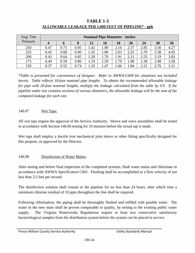
Prince William County Service Authority Utility Standards Manual
100-34
TABLE 1-3 ALLOWABLE LEAKAGE PER 1,000 FEET OF PIPELINE* - gph
Avg. Test Pressure
Nominal Pipe Diameter - inches 4 6 8 12 16 18 20 24 30 36
250 0.47 0.71 0.95 1.42 1.90 2.14 2.37 2.85 3.56 4.27 225 0.45 0.68 0.90 1.35 1.80 2.03 2.25 2.70 3.38 4.05 200 0.43 0.64 0.85 1.28 1.70 1.91 2.12 2.55 3.19 3.82 175 0.40 0.59 0.80 1.19 1.59 1.79 1.98 2.38 2.98 3.58 150 0.37 0.55 0.74 1.10 1.47 1.66 1.84 2.21 2.76 3.31
*Table is presented for convenience of designer. Refer to AWWA-C600 for situations not included herein. Table reflects 18-foot nominal pipe lengths. To obtain the recommended allowable leakage for pipe with 20-foot nominal lengths, multiply the leakage calculated from the table by 0.9. If the pipeline under test contains sections of various diameters, the allowable leakage will be the sum of the computed leakage for each size. 140.07 Wet Taps: All wet taps require the approval of the Service Authority. Sleeve and valve assemblies shall be tested in accordance with Section 140.06 testing for 10 minutes before the actual tap is made. Wet taps shall employ a ductile iron mechanical joint sleeve or other fitting specifically designed for this purpose, as approved by the Director. 140.08 Disinfection of Water Mains: After testing and before final inspection of the completed systems, flush water mains and chlorinate in accordance with AWWA Specification C601. Flushing shall be accomplished at a flow velocity of not less than 2.5 feet per second. The disinfection solution shall remain in the pipeline for no less than 24 hours, after which time a minimum chlorine residual of 10 ppm throughout the line shall be required. Following chlorination, the piping shall be thoroughly flushed and refilled with potable water. The water in the new main shall be proven comparable in quality, by testing to the existing public water supply. The Virginia Waterworks Regulations require at least two consecutive satisfactory bacteriological samples from the distribution system before the system can be placed in service.

Prince William County Service Authority Utility Standards Manual
100-35
SANITARY SEWER SYSTEMS 150 GENERAL REQUIREMENTS 150.01 General: All standards referenced in this section shall refer to the latest revision or revised edition of the referenced manual. The authority for discretionary provisions for sewer designs shall vest with the Director. Any references to acceptance and/or approval shall mean acceptance and/or approval by the Service Authority. Discharges to the sanitary sewer systems shall meet all requirements of the Prince William County Sewer Use Ordinance. 150.02 Private Sewer Service: Building sewer connections, or portions of building sewer connections, outside the VDOT right-of-way shall be privately owned, operated and maintained. They will, however, be inspected by the Service Authority for acceptance by Prince William County. 150.03 Relationship to Waterworks Structures: Public wells, other public water supply sources, structures, and sewers shall meet the requirements of the Virginia Waterworks Regulations with respect to minimum distances from water supply wells or potable water supply sources and structures. No sewer line shall pass within 50 feet of a potable water supply source or structure unless special construction and/or pipe materials are used to obtain adequate protection. The engineer shall identify and adequately address the protection of all potable water supply structures within 10 feet of the proposed project. 150.04 Location of Sewers in Relation to Streams, Estuaries, Lakes and Reservoirs: Sewers entering or crossing streams shall be of sufficient depth below the natural bottom of the streambed to protect the sewer line. In paved channels, the top of sewers shall be placed below the bottom of channel pavement. Sewers shall remain fully operational during a 25-year storm event. Sewers and their appurtenances located along streams shall be protected against the 100-year storm event. Sewers located along streams shall be located in conformance with Prince William County ordinance requirements.
Prince William County Service Authority Utility Standards Manual
100-36
150.05 Sewer-Only Accounts: Under special circumstances, the Service Authority will allow sewer-only accounts. Sewer-only accounts will not be charged water use fees, but the private wells supplying such accounts must be fitted with meters. All water meters used for sewer-only accounts shall meet all of the Service Authority’s standards for size, type, installation and inspection. Meters will be read by the Service Authority in order to establish quantities per billing cycle. The size and location of the water meter shall be shown on the project plans. 150.06 Grease Traps: Private grease traps, volatile liquid separators, or other such devices may be required by the Service Authority for restaurants and other facilities where, due to the nature of the operation, it is deemed necessary or required by the VUSBC or the Service Authority. The owner of the facility served by a grease trap or volatile liquid separator shall be responsible for its proper installation, operation and maintenance. 150.07 Inverted Siphons: Inverted siphons shall not be allowed without the written approval of the Director and only in cases where other alternatives make the use of inverted siphons in the best interest of the Service Authority. 160 DESIGN PARAMETERS 160.01 Tributary Population: Sewer systems shall be designed to carry the peak flows generated by the estimated future population from all contributing points under consideration. The estimated future population will be based on the adopted County Comprehensive Plan for the watershed to be sewered. The estimated average daily flow will be computed using the unit flows from Table 1-4. Consideration will be given to domestic, commercial, institutional, and industrial wastes plus groundwater infiltration in determining the necessary capacity of the sewer system. A design analysis and sewer shed map will be submitted with all project plans.

Prince William
160.02 New sewer plus any flomultiplying from Table are proposesubmission developmenetc, shall beflows other
m County Ser
Design Q
systems wilows pumpedthe average1-4 will be a
ed, a descripof the site
nt are “rules e used whenthan those li
rvice Authorit
Quantities:
l be designed into the we daily flow assumed to cption of the developmenof thumb,” a
n available, tisted in Tabl
ty
100-3
ed to carry thwatershed fro
by the approcover infiltra
procedure nt plans. Tand useful foto more accule 1-4 must h
FIG
Peak
37
he estimatedom a lift staopriate peakation. Whenused for the
The values lior preliminarurately estimhave the wri
GURE 1-1
Flow Facto
Utility St
d peak flow fation. The pking factor frn deviations e sewer desisted for offry planning.
mate the wastten permiss
ors
tandards Man
from the conpeak flow wrom Figure from the flo
sign shall befice, industr Actual landstewater flowsion of the S
nual
ntributing wwill be comp1-1. The unw rates of Te included wrial and comd use, densitws. The useervice Autho
atershed puted by nit flows
Table 1-4 with the
mmercial ty, FAR, e of any ority.

Prince William County Service Authority Utility Standards Manual
100-38
TABLE 1-4
AVERAGE DAILY WASTEWATER FLOWS
Land Use Category Density (Unit/Acre)
Unit Flow/Unit (GPD)
Residential: Urban (UR) 15 - 30 DU 300 Suburban – High (SRH) 8 – 15 DU 350 Suburban – Moderate (SRM) 4 – 8 DU 350 Suburban – Low (SRL) 1 – 4 DU 390 Semi – Rural (SRR) 0.2 – 1 DU 390 Rural (RR) 0.1 – 0.2 DU 390 Agricultural / Estate (AW) 0.1 DU 390 Office: Regional Employment (REC) -- Acre* 2000 Office/Flex (OF) -- Acre 2000 Community (CEC) -- Acre 2000 Office (O) -- Acre 2000 Industrial: Heavy (HI) -- Acre 2000 Light (LIF) -- Acre 1500
Commercial: Regional (RCC) -- Acre 2000 Community (CC, NC) -- Acre 2000 *Note: Acre refers to gross acreage. Office use assumed at an FAR of 0.2. Sanitary sewer design calculations and a sewer shed map will be submitted for all proposed sewer mains as part of the project plans. The sewer design calculations will be in the format as shown on the Prince William County Service Authority Standard Detail Sheet. Actual wastewater flows shall be used in calculations, if this data is available. 160.03 Hydraulic Design Criteria: Sewers shall have a uniform slope and straight alignment between manholes. Sewers will be designed to be free flowing with a hydraulic grade below the crown of the pipe. All sewers will be designed with slopes sufficient to provide a velocity during peak flow conditions of not less than 2.25 feet per

Prince William County Service Authority Utility Standards Manual
100-39
second. Table 1-5 shows the minimum required slopes for some common pipe sizes. Capacity and velocity computations for gravity sewers will be done using the Manning formula as follows: V = 1.49/n R2/3 S ½ Where V = Velocity (fps) n= Roughness coefficient Q = 646.300 (1.49/n A R 2/3 S ½) R= Hydraulic radius S= Slope (feet per foot) A= Cross-sectional area (square foot) Q= Flow rate (gpd) A roughness coefficient (n) of 0.013 will be used for all pipe materials. All sewers will be designed so that the actual depth of flow in the pipe during peak flow conditions will not exceed 80 percent of the pipe’s nominal inside diameter. Due to less flows, upper or terminal sewer runs shall have a minimum slope of 0.80 percent unless there is a distinct possibility of the sewer being extended in the near future. Sewers shall be designed such that the maximum velocity is 10 fps. Where velocities must exceed 10 fps, the sewer shall be constructed of ductile iron pipe conforming to Section 130.01 of this manual. Where smaller sewers discharge into larger sewers, the 0.80 flow line of the pipes must be matched. The minimum size sewer main shall be 8-inches in diameter. The diameter, length, and slope of all proposed sanitary sewer runs will be shown on the profile views of the sewer on the project plans. Table 1-5 shows the minimum slopes in feet per hundred feet.
TABLE 1-5 MINIMUM SLOPES
Sewer Diameter in Inches Minimum Slope
8 0.47 10 0.34 12 0.26 15 0.18 18 0.14 21 0.113 24 0.088 30 0.062 36 0.048 42 0.040
*Note: For sewers larger than 42-inches in diameter, the minimum slope will be computed by the formula –
S = V2/(1.49R2/3/n)2 (V=2.25 fps)

Prince William County Service Authority Utility Standards Manual
100-40
Hydraulic losses at manholes will be accounted for by providing minimum of 0.2 foot difference between the invert in and the invert out for sewer lines up to 12-inches in diameter. At intersections and transitions of sewers larger than 12-inches in diameter, the hydraulic losses shall be computed separately and the hydraulic analysis submitted to the Service Authority for approval. 160.04 Separation of Water Mains and Sanitary Sewers: General – The following factors shall be considered in providing adequate separation:
1. Compliance to VDH and DEQ requirements.
2. Materials and types of joints for water and sewer line.
3. Soil conditions. 4. Service branch connections into the water line and sewer lines.
5. State variations in the horizontal and vertical separations. 6. Offsetting of pipes around manholes.
Parallel Installation:
1. Normal conditions – Sewer lines shall be laid a minimum of 10 feet horizontally from other utilities whenever possible, the distance shall be measured edge-to-edge.
2. Unusual conditions – When local conditions prevent a horizontal separation of 10 feet, the sanitary sewer line may be laid up to 7.5 feet from water lines provided that:
a. A minimum vertical separation of 18-inches between the bottom of the water line and
the top of the sewer line.
b. Where this vertical separation cannot be obtained, the sewer shall be constructed of AWWA approved water pipe, pressure tested in place without leakage prior to backfilling.
c. The sewer manhole shall be of water tight construction and tested in place.

Prince William County Service Authority Utility Standards Manual
100-41
3. Unusual conditions – When local conditions prevent a horizontal separation of 10 feet, the sanitary sewer line may be laid up to 7.5 feet closer than the minimum separation required by the State Corporation Commission.
4. Under no circumstances, including state right-of-way, shall the utilities be installed closer
than the minimum separation required by section 20VAC5-309-140. Excavator's responsibilities to avoid damage, dislocating or disturbances of utility lines in the Code of Virginia.
Crossing:
1. Normal conditions – Sanitary sewer lines crossing below water lines shall be laid to provide a separation of at least 18-inches between the bottom of the water line and the top of the sewer line whenever possible.
2. Unusual conditions – When local conditions prevent a vertical separation described above,
the following construction shall be used: a. Sewers passing over or under water lines shall be constructed of the materials described
in Section 130.01 of this manual.
b. Sewer lines passing over water lines shall be protected by all of the following:
(1) A vertical separation of at least 18-inches between the bottom of the sewer lines and the top of the water line.
(2) Adequate structural support for the sewers to prevent excessive deflection of the
joints and the setting on and breaking of the water line.
(3) The length of the water line to be centered at the point of the crossing so that joints shall be equidistant and as far as possible from the sewer line.
3. A minimum of 12-inches shall be maintained between sanitary sewer lines and utility lines
other than water lines. Sewers or Sewer Manholes: No water pipes shall pass through or come in contact with any part of a sewer manhole. In general, sewers shall be placed along the centerline of the street or travel way. On curved streets, the sewer main shall not vary more than 10 feet on either side of the centerline, except at street

Prince William County Service Authority Utility Standards Manual
100-42
intersections. Manholes shall not be located in areas where storm runoff backs up in the street during a rain event, such as the spread area in front of storm drainage inlets. In state road right-of-ways, the location of all sewers and manholes must meet VDOT’s criteria. On primary and other high volume roads, VDOT may not allow sewers or manholes to be located in the pavement. All other utility lines shall be a minimum horizontal distance of 10 feet, measured edge-to-edge, from all sewer lines and manholes whenever possible. When unusual conditions make it impossible to provide a 10-foot horizontal separation, the required horizontal separation may be reduced as low as 7.5 feet at the discretion of the Service Authority, provided that a minimum vertical separation of 18-inches can be maintained. Sanitary sewer shall be designed to run below the water system. All water lines will cross above sanitary sewers with a minimum vertical separation of 18-inches. The Service Authority may require the sanitary sewer to be constructed of ductile iron pipe when the minimum separation is provided. At all utility crossings, except for water, a minimum vertical separation of 12-inches will be maintained between the utility line and the sanitary sewer. All crossings of streams, estuaries, lakes and reservoirs shall be constructed of Class 52 ductile iron pipe. The pipe shall exhibit no infiltration, and shall be designed, constructed and protected against anticipated hydraulic and physical, longitudinal, vertical and horizontal loads and erosion and impact. Sewers laid on piers across ravines or streams shall be allowed only when it can be demonstrated that no other practical alternative exists. Such sewers on piers will be constructed of Class 52 ductile iron pipe with mechanically restrained joints. Design information and details of the aerial crossings and piers will be included in the project plans. The design engineer shall be responsible for obtaining all required State and Federal permits (such as the Virginia Marine Resources Commission Permit) to install a surface water crossing. All aerial crossings will be designed in conformance with DIPRA recommendations. At stream crossings, the top of the sewer will be a minimum of 1-foot below the stream channel when the stream bed is rock and 3 feet when the stream bed is an unconsolidated material. When the sanitary sewer runs parallel to a stream, the invert of the sewer will be a minimum of 3 feet below the invert of the stream channel to insure that adequate crossings can be made. The invert of the stream channel will be shown on the sanitary sewer profile. When sanitary sewer lines cross gas transmission lines, the sanitary sewer will be constructed of Class 52 ductile iron pipe or the sewer line (unless otherwise directed by the gas company) will be installed in a steel casing running the width of the gas line easement. If the sanitary sewer is constructed of ductile iron pipe, the line will be polyethylene encased in accordance with ANSI/AWWA-C105. If the gas transmission main is constructed of steel pipe, the distance to the nearest anode bed will be shown on the project plans. Test pits will be dug on the gas transmission main at the proposed crossings. The test pit information will be shown on the project plans.
Prince William County Service Authority Utility Standards Manual
100-43
160.05 Manholes: The minimum inside diameter for a manhole shall be 4 feet. A larger inside diameter may be required depending on a pipe diameter and the type of connector used. The inside diameter of the manhole shall be noted on the project plans when the lines connecting to the manhole are greater than 12-inches in diameter. Pipes larger than 24-inches in diameter shall have specially designed manhole structures. Manholes shall be provided at all junctions with other sewers, at all points in change in alignment or grade and at the terminal point of the main. The maximum distance between manholes shall be 600 feet. At all collector system manholes, the difference between the influent and effluent inverts shall not be more than 12-inches. Where the difference occurs, a smooth transition between the pipes, equal in height to 0.80 of the diameter of the pipe, shall be provided. No connections shall be made where the difference in the invert elevations is between 12 and 30-inches. Where the difference in invert elevations is greater than 30-inches, drop connections conforming to the details in this manual will be used. For interceptor sewers larger than 18-inches, the difference in invert elevations may be up to 24-inches. Manholes shall extend above the known level of flooding or, if this is not possible or practical, watertight manhole frames and covers shall be installed. All manholes that do not have watertight frames and covers will be provided with a watertight manhole insert as described in Detail S17.07.00. The manhole insert shall be a No Flow/Inflow Insert, or Rainstopper Insert as manufactured by Southwest Packing and Seals or an acceptable substitute approved by the Service Authority. All manholes will have a manhole chimney seal between the manhole casing, adjusting rings and cone section, as shown on Details S11.07.00 and S12.07.00, to prevent inflow and infiltration into the manhole. On watertight gravity sewer lines, manhole vents conforming to the details shown in this manual will be provided at least every 1,000 foot. Manhole tops located in open areas out of yards, roads, travel ways, and parking areas will be set a minimum of 2 feet above the surrounding finished grade unless otherwise directed by the Director. Under no circumstances will manholes be located in sidewalks or other pedestrian travel ways. Manholes will not be located in parking spaces. Manholes within 1,000 feet or the first 3 manholes downstream (whichever is the greater number of manholes) of discharge points for sanitary sewer force mains shall have interior linings to prevent corrosion. New manholes shall have a corrosion resistant liner. Lining materials shall be approved by the Service Authority. When force mains are tied into existing manholes, the interior of downstream manholes within 1,000 feet or the first 3 manholes downstream (whichever is the greater number of manholes) of the discharge shall be thoroughly cleaned and protected from corrosion by the application of a lining system approved by the Service Authority. The proposed lining system will be shown on the project plans.

Prince William County Service Authority Utility Standards Manual
100-44
Manholes constructed on fill will have a false bottom extending to undisturbed ground or another approved means of preventing settlement of the manhole. All manholes in a project will have a unique alphanumeric identifier on the project plans. The Service Authority will give the Engineer a set of manhole numbers to use within a project. The top elevation of a manhole may be adjusted not more than 1-foot using concrete grade rings. Elevation adjustments greater than 1-foot will require the use of Pre-cast sections. 160.06 Water Tightness: Watertight manhole frames and covers shall be provided for all manholes located outside of paved areas. As a minimum, watertight frames and covers shall be used in areas where the frames will be below the 25-year flood level. Watertight systems shall be vented at least every 1,000 feet. 160.07 Service Connections: Service connections installed from the main to the property line or right-of-way shall have a minimum 4-inch inside diameter. No building service connection to the public sanitary sewer will be allowed to tie into the vertical cleanout riser at the property line allowing a vertical drop to exist in the line. All cleanouts shall have a brass cap. All service connections must be connected by means of a manhole connection, premanufactured tee or wye or with an approved saddle type connection approved by the Director. Service connections to terminal manholes shall not exceed three in number. Service connections to in-line manholes must obtain prior approval of the Service Authority. A sanitary sewer lateral table will be included in the project plans. The table will include the invert of the lateral at the main, the finished floor elevations of the proposed buildings, and the size, length, and slope of the laterals. The lowest floor elevation of any structure to be served by gravity shall be a minimum of 4 feet above the invert elevation of its sewer service connection at the sewer main. For existing structures, connection to the public sewer with plumbing fixtures located on a floor of the structure that is not 4 feet or more above the sewer main as specified above shall not be allowed unless a written waiver is obtained from the Service Authority or a pumping operation is utilized. Cleanouts, if required, shall not be located in a sidewalk, driveway or entrance without the approval of the Service Authority. Sewer laterals shall not be tied directly into a trunk sewer unless specifically approved by the Director.

Prince William County Service Authority Utility Standards Manual
100-45
160.08 Depth of Cover: All sewers, including laterals, with a depth of cover of 18 feet or greater will be constructed of ductile iron pipe. The class of pipe used will be in accordance with Table 1-6. All sewers constructed on fill will be constructed of at least Class 50 ductile iron pipe.
TABLE 1-6 MAXIMUM DEPTH OF COVER
TYPE “4” LAYING CONDITION
-Cement – Lined D.I.P.
CLASS I GRAVEL BEDDING
C900 - PVC** Pipe Class 50* Class 51* Class 52* DR-25*
8 40 40 40 18 10 38 40 40 18 12 36 40 40 18 14 33 38 40 -- 15 -- -- -- 18 16 30 34 40 -- 18 29 32 36 18 20 27 30 34 -- 21 -- -- -- 18 24 23 27 30 18 27 -- -- -- 18 30 18 21 24 -- 33 -- -- -- -- 36 17 20 24 -- 42 16 19 22 -- 48 15 18 21 -- 54 15 18 21 --
*All depths shown in feet. **For depths in excess of 18 feet, Engineer shall provide design data. No sewer shall be installed at depths greater than 20 feet without the written permission of the Service Authority.
Normally, sewers constructed in a street or travel way will have a minimum of 5 feet of cover. Sewer lines may be installed with between 3.5 feet and 5 feet of cover, provided that the sewer is constructed of Class 52 ductile iron pipe.

Prince William County Service Authority Utility Standards Manual
100-46
Sewer constructed in open areas will have a minimum cover of 3.5-feet. Sewer lines may be installed with between 2-feet and 3.5-feet of cover provided that the sewer is constructed of Class 50 ductile iron pipe. Any time the depth of cover is less than two pipe diameters for a significant distance, calculations will be provided showing that buoyant forces will not cause flotation of the line.
160.09 Slope: Sewer lines at a slope of 20 percent or greater will require the approval of the Director and if approved, will be anchored securely as described in Section 170.04. Structural and installation details of the anchors will be included in the project plans. The anchors will be spaced on the sewer line as shown on Table 1-7. All sewers with slopes greater than 14 percent will be constructed of ductile iron pipe. 170 DESIGN STANDARDS – SANITARY SEWERS 170.01 Pipe Materials for Sanitary Sewers:
1. Structural Requirements: The structural design of sewers shall conform with the methods given in the ASCE Manual Number 37 for the design and construction of sanitary and storm sewers. In the use of this manual, the backfill weight shall equal 130 pounds per cubic foot and Ku (normally assumed to be 0.130). The live load for sewers subject to traffic loading shall be determined from a minimum wheel load equivalent to a H-20 loading (16,000 pound wheel load). An allowance of 50 percent of the design wheel load shall be added for impact. A minimum wheel load of 10,000 pounds per wheel shall be applied to all other sewers not subject to traffic load. Ultimate strengths of rigid pipe shall be measured in terms of ultimate three-edge bearing strength divided by a safety factor of 1.5. The allowable load shall be the working strength times a 2.5 load factor for concrete cradle or arch bedding and times a 1.9 load factor in Class B gravel bedding condition.
2. Bedding: Pipes up to and including 18-inches in diameter, except ductile iron, shall be
bedded in compacted granular material placed on cradle or arch bedding. Pipe shall be placed on compacted granular bedding having a minimum thickness of one-fourth (0.25) of the pipe’s outside diameter (4-inches minimum), and the granular bedding shall extend to a depth of 4-inches over the crown of the pipe, completely wrapping the pipe barrel. The granular material shall be gap-graded, crushed stone meeting a minimum of 4-inches of granular bedding. Bedding for pipe larger than 18-inches shall be designed on an individual basis and approved by the Director.

Prince William County Service Authority Utility Standards Manual
100-47
Sewers to be constructed on fill shall require that the finished grade be completed to the pipe invert prior to pipeline bedding preparation. Thereafter, the fill material for the full trench width shall be excavated and replaced entirely with VDOT aggregate 21-A.
3. Pipe Material Selection: The pipe materials listed hereunder have been generally approved
for use in Prince William County. However, the acceptability of specific pipe materials for use within the Service Authority’s service area shall be determined by the Service Authority on an individual basis at the time of review of final project plans. This will necessitate that prospective developers/builders or their engineers contact the Service Authority directly to ascertain its specific pipe material requirements. The type or types of pipe allowable for use on any specific project shall be shown on the approved project plans.
a. Ductile-Iron Pipe: Conform to “Ductile-Iron Pipe Centrifugally Cast in Metal Molds or
Sand-Line Molds, for Water or Other Liquids,” ANSI-A21.51 (AWWA-C151), Thickness Class 50, unless a higher pipe class is needed as determined by the Service Authority (See Table 1-6). Use Class 52 pipe in exposed pipe installations, at stream crossings and for excessive cover where other pipe materials may be subject to crushing. Supply with “Push-On” joints conforming to ANSI-A21.11 (AWWA-C111). Mechanical joint pipe shall be used for aerial crossings. Conform fittings to ASTM-A-21.10 using ductile iron with mechanical or push-on joints. Gravity sewers 12-inches and smaller, may use a standard cement mortar lining. For all gravity sewer lines larger than 12-inches in diameter and all ductile iron force mains, provide interior coating for pipe and fittings conforming to one of the following:
(1) Apply minimum 0.281-inch thick lining consisting of sand and high alumina
cement. Conform to AWWA-C104, except for when cement is used. Protect exterior spigot ends (6-inch maximum) and spigot face with 8 mil epoxy coating. Protect interior faces of bell, including gasket cavity, and all interior surfaces of fittings with like thickness of epoxy coating.
(2) Apply minimum 40 mils (dry film thickness) Ceramic Epoxy Lining to pipe and fitting interiors. Protect gasket area and spigot ends (6-inch maximum) with 6 mils nominal, 10 mils maximum Protecto Joint Compound. Apply all material according to manufacturers’ specifications. The ceramic epoxy must be a high build multi-component Amine cured Novalac Epoxy Lining, Protecto 401 or approved substitute. Test every section of pipe and every fitting for pinholes with a nondestructive 2,500 bolt test.
b. Polyvinyl Chloride (PVC): PVC sewer pipe shall be manufactured in accordance with
AWWA designation C900 (DR 25). Gravity sewer pipe shall be unplasticized polyvinyl chloride with integral rubber ring wall bell and spigot joints furnished in 18-
Prince William County Service Authority Utility Standards Manual
100-48
foot nominal lengths. Installation of PVC gravity sewer pipe and fittings shall be in accordance with ASTM designation 2321 and manufacturers’ recommendations. PVC sewer pipe shall be stored in accordance with manufacturers’ recommendations on flat, even surfaces and shall remain racked on the pallets as delivered to the job site until such time as the trench is ready for the placement of the pipe; e.g., PVC pipe shall not be strung out on the job site. Pipe stored for more than one year prior to installation shall be covered with an opaque covering to prevent damage by the sun.
c. There will be no change in pipe material from manhole to manhole unless approved by
the Director. 170.02 Manholes: Manhole sections shall be Pre-cast and manufactured in accordance with ASTM-C478. Each section shall have lifting lugs or keyways for the purpose of handling and setting. Joints shall be of O-ring rubber gasket type or other jointing system approved by the Service Authority. The joint design shall meet the requirements of ASTM-C443. Gaskets shall meet the requirements of ASTM-C361. When assembled, the joint shall be uniform and watertight. Steps for manholes shall be made of fiberglass, cast iron or steel and shall have a plastic coating. Steps will be set in the manholes as shown on Detail S06.07.00. All manholes with standard frames and covers shall be equipped with watertight manhole inserts as shown in Detail S17.07.00. The manhole insert shall be a No Flow/Inflow Insert, or Rainstopper Insert, as manufactured by Southwest Packing and Seals, or an acceptable substitute approved by the Service Authority. Castings shall be of best quality, tough, gray iron, free from cold shuts, blow holes, and other imperfections and shall meet the requirements of ASTM-A-48, Class 30. The castings shall be sound, true to form and thickness, cleaned by sandblasting and neatly finished. The bearing surfaces shall be machine ground and finished to insure satisfactory seating and anti-rocking. Covers shall receive one coat of black asphaltum paint at the factory. Standard covers shall be furnished in conformance with Detail S13.07.00. Watertight covers shall be furnished in conformance with Detail S14.07.00 and used in easements and remote locations. Watertight frames and covers shall be anchored to the manhole as shown in Detail S11.07.00.

Prince William County Service Authority Utility Standards Manual
100-49
170.03 Casings and Tunnels: Pipelines which must be bored or tunneled under a roadway, or other natural obstruction, shall be installed in a steel casing or tunnel. Pipe in casings and tunnels shall be constructed of a minimum of Class 52 ductile iron pipe with restrained joints. Prefabricated stainless steel pipe supports with non-conductive skids or another acceptable support system will be provided to support the pipe. Pressure treated timber skids shall not be permitted. Install casings and tunnels on a slope so they will drain. Casings will conform to the details provided in this manual. Provide complete design information for a utility tunnel in the project plans. When extending casings, due to road widening projects, split casings with concrete footer may be considered. 170.04 Anchors: Sewer lines approved for slopes of 20 percent or greater shall be anchored securely with concrete anchors or other approved method. Structural and installation details of anchors shall be included in the project plans. Space anchors as shown on Table 1-7. Sewers with slopes greater than 14 percent will be constructed of ductile iron pipe.
TABLE 1-7 ANCHOR SPACING
Percent Slope of Sewer Anchor Spacing
(Center to Center) 20-35 36 Feet 35-50 24 Feet
Over 50 16 Feet 170.05 Sewer Service Connections: The following standards shall apply to sewer service connections that are located within dedicated right-of-ways and easements. These service connections will be constructed of hub and spigot cast iron pipe (extra heavy, conforming to ASTM-A-74) PVC sewer pipe conforming to AWWA-C900 (DR 25) or schedule 40 PVC pipe conforming to and dual marked as ASTM-D1795 and ASTM-D2665. Sewer service connections with a depth of cover of 18 feet or greater will be constructed of Class 50 ductile iron pipe to the property line. PVC DR 25 joints shall be made with integral rubber ring wall with bonded-in-bell elastomeric seal. The schedule 40 PVC joint shall be made with a solvent weld bell and spigot joint using PVC pipe glue as supplied by the manufacturer. No solvent weld joints will be permitted within the state right-of-way. No-hub pipe shall not be permitted.

Prince William County Service Authority Utility Standards Manual
100-50
180 DESIGN STANDARDS – LIFT STATIONS 180.01 General Requirements: Wastewater (or sewage) lift stations will be designed in conformance with the Commonwealth of Virginia Sewerage Regulations. Additionally, all sewage lift stations within the Occoquan Basin will comply with the design requirements of the Occoquan Policy. No structure tributary to a proposed lift station will be certified for construction by the Service Authority until the following items have been provided:
1. A “Certificate to Operate” the lift station from the Virginia Department of Environmental Quality;
2. Five copies of the Operations and Maintenance Manual approved by the Service Authority
and the Virginia Department of Environmental Quality; 3. Certified pump curves;
4. A certificate of substantial completion issued by the Service Authority.
Lift stations will be located above the level of the 100-year flood/wave action. The fee simple ownership of the lift station lot will be transferred to the Service Authority. The lift station lot will be fenced and screened/landscaped as required in the Prince William County DCSM. Lift stations will be designed for the peak flow from the drainage area. The peak flow for a lift station will be a minimum of 2.5 times the average daily flow, unless otherwise directed by the Service Authority. Pump curves, flow calculations and a drainage area map will be included in the project plans for lift stations. All lift stations will have at least two pumps. For stations with two pumps, each pump must be able to pump the design peak flow with the other pump out of service. For lift stations with more than two pumps, with the largest pump out of service, the remaining pumps must be able to pump the design peak flow. Lift stations with a peak design flow of one million gallons per day (MGD) or less may be designed as submersible stations. Lift stations with a peak design flow of greater than one MGD shall be designed in a wet well/dry well configuration. The Service Authority has established a procedure for the review of pump stations plans. The engineer is encouraged to meet with the Service Authority prior to start of design to discuss the Service Authority’s procedures and requirements. The project plans will include all of the structural, electrical and mechanical design information and details necessary to construct the station. The three types of sewage lift stations used by the Service Authority are:
1. Temporary Lift Station: A temporary lift station will be used to serve a single subdivision or commercial site. The location of the station does not conform to the Service Authority’s

Prince William County Service Authority Utility Standards Manual
100-51
master sewer plan and the station will be abandoned when gravity sewers reach the station. Temporary stations shall meet all of the design and construction criteria specified in the USM.
2. Interim Lift Station: An interim lift station shall be designed to serve the portion of the
sewer shed upstream of the station site. The station is in conformance with the Service Authority’s master sewer plan except that, due to financial considerations, it is not located at the base of the sewer shed. The station will be abandoned when the permanent lift station and associated interceptor sewers are constructed. Interim stations are subject to a special review process by the Service Authority.
3. Permanent Lift Stations: Permanent lift stations shall be designed and sited to serve the
entire sewer shed service area. A permanent station may not be initially constructed with capacity for the entire sewer shed, but the major structures in the facility will be designed to accommodate the ultimate capacity of the station. Permanent stations are normally identified within the Service Authority’s Capital Improvement Plan. Permanent stations are subject to a special review process by the Service Authority.
180.02 Design Criteria: All sewage pumping stations will be designed in accordance with the following criteria. Additional requirements of DEQ’s Sewage Conveyance and Treatment regulations shall also apply.
1. Pumping Units: All pumps shall be warranted against defects in workmanship and material for a period of five years or 10,000 hours of operation by the Municipal Wastewater-Permanent Installation Warranty Policy under normal use, operation and service. The warranty shall be non-prorated. Submersible pumps shall be as manufactured by Flygt or an acceptable substitute approved by the Director during the design phase. All pumps using a center shaft shall be equipped with oversized bearings (Class B).
a. Protection Against Clogging: All pumping stations will have a comminutor basin at the
influent end of the station. The comminutor will be sized for the estimated peak flow into the station. The comminutor will be designed to be easily removable from the flow channel without disturbing any piping connections. The comminutor channel shall be designed to settle out grit upstream of the screening area. On larger stations, a separate grit chamber may be required. Comminutors shall be designed for continuous operation and will automatically restart after power failures. The basin shall also be equipped with a bypass manual bar screen and flow diverter so that the comminutor can be taken out of service for repair and maintenance. The clear openings on the bar screen will not exceed 2.5-inches in any dimension.

Prince William County Service Authority Utility Standards Manual
100-52
b. Pump Openings: All pump openings and passages shall be large enough to permit the
passage of a sphere 3-inch in diameter and any trash that can pass through a 4-inch house collection system. All pumps will have cleanout ports.
c. Controls: All pumps will be controlled by a bubbler system. The bubbler system shall
have a 12 gallon reserve air tank to operate the system in the event of a compressor failure. The bubbler system shall have dual oil-less air compressors and the compressors shall be fed from separate dedicated electrical circuits. Bubbler systems shall include manually operated purge controls. The compressors shall have lead/lag and alternation capabilities. The bubbler system shall include an air flow rotometer scaled from 0 to 2.0 SCFH (see sample bubbler system diagram). The bubbler system air compressor shall be Thomas Air Compressor, Part #TA4101D12MA or an approved substitute.
Primary Pump Controls shall consist of a D150 Series controller as manufactured by Consolidated Electric Company or an approved substitute. Where variable speed pumps are specified, a set point/speed controller shall be used in addition to the pump controller specified above. The speed controller shall be as manufactured by Benshaw or an approved substitute. Check valve limit switch circuitry shall be used for pump failure logic. In extended shaft applications, vibration and temperature monitors shall be used. An elapsed run time indicator will be provided for every pump. A press-to-test circuit will be provided for the control panel indicator lights. All control wiring and interfacing wiring shall be number coordinated with a schematic. All instrumentation and control devices shall be wired and stranded copper conductors. All panel and field wiring shall be identified with non-repeating numbers. All motor control centers shall be equipped with a motor overload indicator light for each motor equipped with a thermal overload protection device.
d. Valves and Piping: Valves shall be located on the suction and discharge lines of each
pump to allow the pump to be isolated. A check valve shall be installed on each discharge line, between the pump and the valve. The velocity in the suction line will not exceed 6 fps and will not exceed 8 fps in the discharge line. Pressure gauges with isolation valves will be installed on the discharge side of the check valve. Gauge taps with valves will be installed on the suction and discharge side of each pump. Where necessary, a discharge surge arrestor will be provided. The surge arrestor will be valved so that it can be taken out of service without shutting down the force main. Flexible connections shall be provided for all below grade pipe connections to concrete structures. A tee and necessary valving shall be provided on the discharge force main to allow the force main to be drained and allow an emergency bypass connection.

Prince William County Service Authority Utility Standards Manual
100-53
e. The soft starts shall be capable of automatic restart after power failures. Pumping units
shall have soft start/smooth stop controls as manufactured by Eaten/Cutler Hammer.
2. Lighting: Adequate lighting will be provided throughout the station. All lighting fixtures shall be rated for the environment in which they were installed. Where fluorescent fixtures are used, they shall be installed in accordance with the manufacturer’s recommendations to provide adequate head dissipation and maximize the life expectancy of the fixture. Fluorescent fixtures shall have a 0°F start ballast and have a plastic lens to protect the lamps. Fluorescent fixtures shall use F40 lamps and shall be constructed so as to allow the entrance of conduits to the ends of the fixture. A skylight will be installed in the generator and control building to provide natural light. All lighting located in a wet well shall be serviceable from the catwalk. All lighting located in a dry well shall be vapor proof, corrosion resistant, and shall be mounted with stainless steel hardware. All exterior-photoelectric switches shall be intrinsic.
3. Ventilation: Ventilation shall be provided for all lift stations during all periods when the
station is occupied. Where the pumps are below ground, mechanical ventilation is required and shall be so arranged so as to independently ventilate all of the wells and/or vaults at the station. No damper shall be used on the exhaust or fresh air ducts, and there will not be any fine screens or other obstructions in the ducts that may cause clogging. The switches for the operation of the ventilation equipment shall be well marked and located above grade near the entrance hatches. The lighting and ventilation switches on all wet wells shall be interlocking. If three-phase service is available, the exhaust fans motors shall be three-phase motors. Time clock switches will be provided to allow a programmed run time of the exhaust fans. There will be no interconnection between the ventilation systems in the wet well and dry well.
a. Wet Wells: Ventilation may be either continuous or intermittent. Ventilation, if
continuous, shall provide at least 12 complete air changes per hour; if intermittent, at least 30 complete air changes per hour. All wet well electrical equipment and devices shall be explosion proof. Wet well ventilation fans and ducts shall be constructed of either stainless steel or fiberglass.
b. Dry Well: Ventilation may be either continuous or intermittent. Ventilation, if
continuous, shall provide at least six complete air changes per hour; if intermittent, at least 30 complete air changes per hour.
4. Flow Measurement: All pumping stations will be equipped with a magnetic flow meter that
has an output of between 4 and 20 milliamps. The flow meter shall be a ABB Magmaster or an acceptable substitute approved by the Service Authority. All flow meters will have

Prince William County Service Authority Utility Standards Manual
100-54
manufacturer’s start-up and calibration. Valves will be installed on each side of the flow meter and a by-pass will be installed around the flow meter vault. A circular chart recorder with a totalizer shall be provided for the flow meter. Flow meter circular charts shall be dual pen units. Magmeters shall be installed with grounding rings on each side of the sensor. The chart recorder and all other flow metering equipment, except for the sensor, will be located in a generator and control building. The flow meter shall be installed with grounding rings. A year’s supply of charts should be provided with the flow meter.
5. Water Supply: Wherever possible, public water will be extended to the pumping station for wash down and cleanup operations. The water service into the station will be a 2-inch, type “K” copper, or a 4-inch ductile iron service line with a 1.5-inch water meter. The meter will be set as shown in the details of this manual. If public water is not available, a well will be provided at the site. Appropriate cross connection measures shall be used to insure that no physical connection exists between any potable water supply and a sewage pumping station that under any conditions might cause a contamination of the potable water supply. A non-freeze yard hydrant will be installed at the station. A 50-foot long hose and a hose rack will be provided at the control building. When required, restroom facilities will be provided at pump stations.
6. Structures: Access hatches will be located in the station so as to facilitate the removal of
the pumps, motor and other equipment in the station without disrupting the operation of the facility. All hatches will be aluminum with stainless steel hardware. All hatches will have locking hasps and automatic hold-open arms. A fixed or portable hoist suitable for removing the comminutor, pumps and other equipment will be provided at the station. If a portable hoist is provided, wall sockets will be installed at the comminutor basin and pump well. The comminutor basin, valve vault, and flow meter vault will have floor drains. The floor drain will have a “P” trap and will discharge into the wet well. The floor drain shall be installed with a check valve or flapper valve to prevent sewage from entering the structures if the wet well floods.
a. Wet Wells: The wet wells at stations three (3) million gallons a day or larger shall be
divided into two interconnected sections to facilitate repairs and cleaning. The effective capacity of the wet well shall be such that one pump will run continuously at least 5 minutes of every 30-minute period at the minimum flow. The wet well fillets shall have a minimum slope of one-to-one to the hopper bottom. The hopper bottom shall be no larger than necessary for the proper installation and function of the inlet. All wet wells shall be polycrete or have a lining system to prevent corrosion. The wet well size and control settings shall be designed to avoid heat buildup in the pump motor due to
Prince William County Service Authority Utility Standards Manual
100-55
frequent starting and to avoid septic conditions due to excessive detention times. A visual gauge of the wet well level shall be provided.
b. Generator and Control Building: An approved brick and block building shall be
provided to house the electrical and control equipment. The generator and control building for interim and permanent lift stations will be designed on a case-by-case basis. The building shall be sized to accommodate all of the proposed equipment and to provide adequate space for personnel to operate and repair the equipment in the building with the access doors closed. A thermostatically controlled heater and exhaust fan sized for the building will be provided in the control building. The exhaust fans shall be adequately sized to cool the heat generating equipment located in the building. The thermostats controlling all HVAC equipment shall be located in an easily accessible area.
7. Reliability: All pumping stations will be reliability Class I. Electric power shall be
provided to the station by distribution lines and by an emergency generator. Both power sources shall be sufficient to operate the pumps, critical lighting and ventilation systems during peak flow conditions. The distribution lines and the generator shall have a means of being disconnected before the generator switch gear. The generator will automatically switch on-line in the event of a power failure. The generator switch gear will be fully automatic with the ability to sense a single-phase power condition and switch to the generator power system with a minimum time delay. Both power sources shall be protected by fuses or breakers prior to the transfer switch. The transfer switch shall be capable of being operated manually. a. Lift Station Power System Design: The station’s power supply shall be protected from
lightning. A final step-down transformer shall be provided on each electric feed line with adequate physical separation between them to prevent a common mode failure. Separate buses shall be provided for each power source. The electric transmission line and the emergency generator will remain separate and form separate distribution substations up to the internal bus system transfer switch to preclude a common mode failure of both sources. Breaker settings or fuse ratings shall be coordinated to effect sequential tripping such that the breaker or fuse nearest the fault will clear the fault prior to activation of other breakers or fuses to the degree practical. All lightning transformers shall be pad mounted. The load distribution panel shall not be an internal part of the transformer.
b. Equipment Location: All electrical switch gear and controls will be located in a
building. Any equipment remotely located from the distribution panel shall have a lockable service disconnect on the line side. The generator will be located on a concrete

Prince William County Service Authority Utility Standards Manual
100-56
pad inside the pump station lot. A prefabricated enclosure will be provided to protect the generator from the weather. Fuel for the generator will be stored in a skid mounted tank. Skid mounted tanks shall be double-walled for leak containment and shall meet all DEQ and EPA regulations. The fuel tank will be sized to hold adequate fuel to run the generator for 24 hours. A fuel storage level indicator will be provided in the generator and control building. The generator will be equipped with a block coolant heater. The generator will be equipped with an alarm indictor to display the cause of a generator failure. The means for starting an emergency generator shall be completely independent of the normal electric power source. The starting system shall be sufficient to start the generator a minimum of three times without recharging. The starting system shall be alarmed and instrumented to indicate a loss of readiness.
All motors and control enclosures will be adequately protected from moisture, the weather and water under pressure. Indoor motors will be of a splash resistant design. All equipment shall be installed in accordance with the manufacturer’s recommendations. When laying out the location of the equipment in the control and generator building, the engineer will consider the necessary separation between devices to provide adequate ventilation and the location of door, hatches and panel covers to avoid conflicts between these items when they are opened and closed. Also, provide provisions for housekeeping pads to keep equipment off of the floor. Any equipment located outside of the control building will be located in a moisture proof, NEMA 4 x enclosure constructed of non-corrosive materials.
c. Equipment Type:
(1) The electrical equipment in the generator and control building, wet well, dry well
and the valve vault, will comply with the appropriate requirements of the National Electric Code. No aluminum bus bars, wire, connectors or lugs shall be allowed.
(2) Three-phase motors and their starters will be protected from electric overload and short circuits on all three-phases.
(3) All motors will have a low voltage protection device which will cause and maintain the interruption of power to the motor upon the reduction or failure of voltage.
(4) Temperature detectors shall be provided in the stators and bearings of larger motors
to indicate overheating problem.
(5) All wires installed in underground conduits will have moisture resistant insulation as identified in the National Electric Code. All wiring installed in raceways shall be
Prince William County Service Authority Utility Standards Manual
100-57
THHN stranded wire. Electrical cables shall be type SO with sunlight and ultraviolet protection. All 4 – 20 MADC signal cables shall have shielding properly terminated on one end of the cable run.
(6) Concrete, metals, control and operating equipment, and safety devices will be constructed of corrosion resistant materials. All surfaces not otherwise protected shall be painted. A painting schedule shall be included in the project plans.
(7) Electrical power devices or equipment used to convert single-phase power to three-phase power will be dedicated to a single specific motor.
(8) All surface mounted electrical device boxes and small junction boxes subject to moisture shall be Crouse Hinds cast device boxes constructed of non-corrosive materials. All boxes shall have mounting lugs. Drilling mounting holes in the back of the box is unacceptable. Gasketed covers with stainless steel screws will be provided for all boxes. The covers will be from the same manufacturer as the boxes. All boxes will be mounted with stainless steel hardware. Moisture proof bell boxes are not acceptable.
(9) Any cable subjected to stress or strain shall be equipped with a stainless steel wire mesh strain relief fitting that is properly sized for the cable. All cables shall be routed and installed so as to be protected from stress, crush and abrasion hazards.
(10) Generators shall be manufactured by Cummins or Onan. The generator switch gear shall be provided by the same manufacturer as the generator. All electrical distribution equipment shall be manufactured by Cutler Hammer. The motor starters shall be Citation Series. Electrical equipment shall be protected by a Solid State Advanced Control Phase Monitor, Model RLM 911 (480 volt) or Model RLM 611 (240 volt). The generator shall be equipped with a battery charger and block heater. The transfer switch shall include a plant exerciser, adjustable time delays between all functions and transitions. The switch shall also be capable of holding in the “neutral” position for an adjustable time period between all transitions. The generator’s fuel tank will be filled after all start up testing is completed.
(11) All electrical enclosures located indoors, except in wet wells, and above grade shall be NEMA 4. All enclosures located below grade and outdoors shall be NEMA 4X. Electrical enclosures located in the wet well shall be explosion proof and corrosion resistant. All pulling devices and junction boxes in the wet well shall be PVC coated.

Prince William County Service Authority Utility Standards Manual
100-58
(12) Wiring conduit shall be galvanized rigid conduit no smaller than .75 of an inch in diameter except for conduits located in the wet well. Conduits located in the wet well shall be PVC coated rigid conduit no smaller than .75 of an inch in diameter. Conduits shall be sized to facilitate wiring for the ultimate design conditions. The rigid conduit will be recoated with PVC at all locations where the coating was removed during the installation of the conduit. All conduit straps used in the wet well will be PVC coated. All other conduit straps shall be corrosion resistant. Fasteners used outdoors and below grade shall be stainless steel. Channels used to mount electrical equipment or conduits shall be aluminum or other material approved by the Service Authority.
(13) All foreign sources of electrical power entering a control cabinet or motor control cabinet shall be identified and a means of disconnecting the power shall be provided.
d. Controlled Overflow Diversion: A retention basin will be provided at all lift stations unless this requirement is waived by the Virginia Department of Environmental Quality. The retention basin will be sized to hold the estimated 24-hour flow volume.
8. Alarm Systems: All lift stations will be monitored by the Service Authority’s Supervisory
Control and Data Acquisition (SCADA) system. The SCADA system will be installed by the Service Authority. The Service Authority shall be reimbursed for the cost of the SCADA system and its installation by the contractor/developer. Dry, normally open contacts will be provided for all status and alarm circuits. This will include pump run/fail, generator run/fail, high wet well, AC power status, generator starting system loss of charge and pump overload. A description of SCADA status and alarm circuits is listed below. Both audible and visual alarms will be provided at the pumping station. A press-to-test circuit will be installed for all of the control and alarm panel indicator lights. High wet well, generator fail and power fail alarms shall function upon complete loss of power. All alarms shall clear after events return to normal (no latching alarms to SCADA). An antenna pole will be installed at the station near the control building for the SCADA antenna. The location of the antenna pole will be shown on the project plans. a. SCADA Field Wired Circuits:
(1) Pump Run Status: Provide normally open contact wired to an auxiliary contact on the motor starter.
(2) Pump Fail Status: Provide normally open contacts wired to a check valve fail circuit
using limit switches and time delay relays to cover all possible malfunctions.

Prince William County Service Authority Utility Standards Manual
100-59
(3) Power Fail: Provide normally open contacts wired to a phase monitor which is sensing power on the load side of the main commercial power disconnect. The phase monitor shall be a Model RLM 911 (480 volt) or Model RLM 611 (240 volt) as manufactured by Solid State Advanced Control.
(4) High Wet Well: Provide normally open contacts wired to a float switch in the dry
well.
(5) High Influent Channel: Provide normally open contacts wired to a float switch in the influent channel upstream of the comminutor or screening device.
(6) Generator Run Status: Provide normally open contacts wired to the generator’s
internal controls or use a phase monitor sensing the power being generated.
(7) Generator Failure: Provide normally open contacts wired to the generator’s internal controls or wired to a pneumatic timer which is energized by two legs of the load side of the transfer switch. This circuit must be wired to activate on all failure events.
(8) Flow Meter Signal: The flow meter’s analog signal of between 4 and 20 milliamps
shall be wired to a loop isolator. The loop isolator output shall terminate to the SCADA system. The loop isolator shall be a Model API 4300 as manufactured by Absolute Process Instruments, Inc.
(9) Generator Run Alarm: This circuit shall be wired to an adjustable time delay relay
that is field wired parallel to the generator run relay. The time delay on this relay shall be set at one hour.
(10) Special Points: The Service Authority shall have the option of requiring special
points field wired to the SCADA system. The Service Authority will provide the wiring information for these points during the review of the project plans.
9. Instructions and Equipment: Five copies of the approved Operations and Maintenance
Manual will be supplied to the Service Authority prior to completion of the station. The Operations and Maintenance Manual will be reviewed and approved by the Virginia Department of Environmental Quality and the Service Authority. The Operations and Maintenance Manual will contain a reduced set of the lift station plans, including as-built electrical and control schematics. All necessary tools and spare parts will be supplied with the station. Copies of all equipment manuals and warranties will be provided to the Service Authority.

Prince William County Service Authority Utility Standards Manual
100-60
10. Access and Security: A 12-foot wide, paved access road will be provided to the lift station.
The minimum road section will consist of a compacted sub-grade, 6-inches of VDOT 21-A stone and 2-inches of compacted VDOT SM-2A bituminous concrete. The grade on the road will not exceed 10 percent. Unrestricted ingress and egress will be granted to the Service Authority from a public right-of-way to the pumping station. On long access roads, a locking gate will be provided at the entrance to the access road from the public right-of-way.
An unrestricted, all weather access road to the station will be maintained by the contractor/developer until the permanent access road is complete and accepted by the Service Authority. The Service Authority shall have access to the station at all times. An 8-foot high, black or green chain link security fence topped with barbed wire shall be provided around the pumping station lot. The fence shall be equipped with a top rail and a bottom tension wire. Access into the station will be through a 12-foot wide, lockable gate. All door locks and padlocks in the station will be keyed to the Service Authority’s standard keys. Adequate provisions will be made for parking and turning vehicles around at the station.
11. Spare Parts and Special Tools: The Service Authority shall be provided with sufficient
spare parts for all major equipment. A specific spare parts list will be generated by the Service Authority after the review of the equipment submittals for the lift station. Special tools may also be required for a given station that uses special (non-standard) equipment. Special tools shall be specified during the review of the lift station plans by the Service Authority.
12. Odor Control: Odor control measures must be designed and installed as part of the station.
The required odor control measures used at a station will be determined during the review of the plans for the station.
13. Sump Pumps: In installations where sump pumps are required, the sump pumps shall have a minimum discharge rate of 40 gpm. Sump pumps shall be Zoeller 98-0006, Model M98-B pumps or an acceptable substitute approved by the Service Authority.
14. Protective Coatings: The project specifications will specify a paint or other protective coating for all corrodible materials not otherwise protected. The type, color and thickness of the paint or other protective coating are subject to the approval of the Service Authority.

Prince William County Service Authority Utility Standards Manual
100-61
180.03 Force Mains: The minimum force main size will be 4-inches except for grinder pump systems. The flow velocity in the force main shall not be less than 2 fps, nor more than 8 fps. Air release valves, conforming to the details shown in this manual, will be provided at the high points in the force main. Blow-off pits will be installed as directed by the Service Authority at low points in the force main. Force mains will be adequately anchored within the pumping station and throughout the line. The number of bends in the force main will be minimized. Restrained joints will be provided at all bends and other required locations. A resilient seat wedge valve shall be provided on the force main just outside of the flow meter vault. The force main shall enter the receiving manhole at no more than 1 foot above the flow line of the manhole. The force main shall enter the receiving manhole with its centerline horizontal. The receiving manhole shall be lined with a corrosion resistant material as approved by the Service Authority. All force mains will be constructed of pressure type pipe with pressure type joints. All force mains will be constructed of ductile iron pipe unless otherwise approved by the Director. Class 52 ductile iron pipe will be used for force mains 12-inches in diameter and smaller. Force mains larger than 12-inches in diameter will be constructed of Class 51, ductile iron pipe. The interior coating of ductile iron pipes shall conform to Section 170.01.C.1 of the USM. All bends and fittings shall be pressure rated and will meet all applicable AWWA Standards. A No. 12 solid copper tracer wire or other locating system will be installed with all non-metallic force mains. The force main will be tested at a minimum pressure of at least 50 percent above the design operating pressure but not less than 100 psi for at least 30 minutes. Leakage will not exceed the criteria of AWWA Standard C600. Pipe bedding will conform to the pipe manufacturers’ recommendations. 180.04 Grinder Pumps: Grinder pump systems shall only be used where there is no reasonable way to provide gravity sewer service to the property. All grinder pumps for new subdivisions will be owned and maintained by the property owner. Unless otherwise directed, each structure and/or lot in a project will have a separate pump. It will be the property owner’s responsibility to obtain the necessary approvals and permits from Prince William County and the Virginia Department of Environmental Quality for the installation of the grinder pump. All grinder pumps will have a high water alarm installed in the structure that the pump serves.

Prince William County Service Authority Utility Standards Manual
100-62
The Service Authority will accept the maintenance responsibility for a common force main that serves more than one grinder pump, provided that the force main is installed in a public right-of-way or in a dedicated easement. System calculations shall be provided to show that acceptable flow velocities can be maintained under all conditions of flow (See Section 180.03). Corporation stops and ball valves shall be installed where discharge lines from grinder pumps tie into a common force main. Flushing stations, conforming to the details provided in this manual, will be provided on the common force main. All applicable standards of Section 180.02, and Section 180.03, of this manual shall be incorporated in the design of grinder pump systems. 190 SANITARY SEWER CONSTRUCTION 190.01 General Requirements: Construction of sanitary sewer and appurtenances within the Service Authority service area shall be in accordance with plans and specifications approved by the Service Authority.
1. Handling of Materials: Load and unload pipe, fittings, valves, and accessories by lifting with hoists or skidding so as to avoid shock or damage. Under no circumstances shall such material be dropped. Handle pipe such that the coating and lining shall not be damaged. The Service Authority Field Inspector has the authority to reject any and all materials found damaged.
2. Line and Grade Stakes: Prior to the construction of an approved sanitary sewer, the engineer shall place adequate line and grade stakes identifying the sewer main, sewer laterals, and other appurtenances to insure the system can be constructed in accordance with the approved plans.
3. Cut Sheets:
a. The engineer shall prepare legible cut sheets at 100-foot stations. Cut sheets will contain all data pertinent to the construction of the sewer main, the station and length of service connections, the location of all concrete encasements or cradles and the finished grade of all manhole rims.
b. Five (5) sets of cut sheets, certified by a Professional Engineer or surveyor shall be
submitted to the Service Authority for review and approval. The engineer or surveyor who certifies the cut sheets shall also provide the following statement on all sets: “The professional seal and signature appearing on this document certifies that information shown conforms to the approved plan and/or actual field conditions.” If a deviation from the approved plans in the horizontal location or grade of any main, structure or

Prince William County Service Authority Utility Standards Manual
100-63
appurtenance is necessary; a revision to the approved plans showing the proposed deviation must be submitted to the Service Authority for review and approval before the changes are constructed.
190.02 Excavation:
Excavation shall conform to the lines and grades shown on the approved project plans and cut sheets. The slope of the sides of the excavation shall be kept as nearly vertical as possible and consistent with the types of materials encountered. Where required to maintain safe working conditions, trench walls will be sloped or benched. Maintain a clear area a sufficient distance back from the edge of the excavation to avoid overloading which may cause slides, cave-ins or shifting of the pipe. The contractor/developer shall provide sheeting, bracing and shoring necessary to perform the work and protect existing structures and excavations in accordance with Virginia OSHA Regulations. The width of the trench from the foundation to 12-inches above the pipe shall not exceed the maximum width as shown in Table 1-8.
TABLE 1-8 MAXIMUM TRENCH WIDTH
Nominal Pipe Diameter (in.) 8 10 12 14 15 16 18 20 21 Max. Trench Width (in.) 42 42 42 42 42 42 44 44 48 Nominal Pipe Diameter (in.) 24 27 30 33 36 42 48 54 Max. Trench Width (in.) 51 55 60 63 69 78 87 96 The bottom of the trench shall be accurately graded to provide a uniform bearing and support for each section of pipe on undisturbed soil along the entire length of the pipe, except where it is necessary to excavate for bell holes and for the proper sealing of pipe joints. Bell holes and depressions for joints shall be only of such length, depth and width as required to make a proper joint. Bell holes and depressions for joints shall be backfilled with granular material and compacted. Do not carry excavation below the established grades unless unsuitable materials incapable of supporting the pipe are encountered. Wherever the soils encountered at the trench bottom are incapable of adequately supporting the pipe, the trench shall be over excavated until a stable foundation is reached. Fill the over excavation with a granular material having a maximum particle size of 1-inch, place in 6-inch lifts and compact until the trench bottom is brought to grade. Remove and properly dispose of all water entering the trench excavation. Dewatering equipment shall be sized to maintain the trench in a satisfactory condition for pipe laying. Pipe laying will be permitted only where the depth of water is maintained below the invert of the pipe joint. Dispose of water in a

Prince William County Service Authority Utility Standards Manual
100-64
suitable manner without damage to adjacent property or in a manner protective of public health and convenience. Do not open more than 150 feet of trench in advance of completed pipe laying. Excavation at manholes and similar structures shall be sufficient to have a minimum of 12-inches of clear area between their outer surface and the embankment or sheeting. Conduct blasting operations in accordance with existing ordinances and regulation. After blasting or other approved methods of removal, no projection of rock shall remain nearer than 6-inches to any part of the sewer pipe when laid or shall they project beyond the lines and grades of masonry structures. Do not blast within 40 feet of a completed sewer. Cover the ends of sewers adjacent to blasting operations to prevent debris from entering the sewer. 190.03 Backfill: Backfill in areas subject to vehicular traffic or structural loading shall begin at the top of the granular bedding and placed in lifts no greater than 8-inches thick. Compact each lift to 95 percent of the maximum dry density as determined by ASTM-D698, AASHTO-T99 or VTM-1. Backfill material shall be free of organic materials, frozen clods, highly plastic silts or clays and other unsuitable materials. Rock pieces, larger than 1-inch in any dimension, shall not be used in the backfill, which is within 2 feet of the pipe. Stone or rock larger than 10-inches in any dimension shall not be used in the backfill for sewers or structures. Backfill in areas not subject to vehicular traffic shall be compacted to 90 percent of the maximum dry density as determined by ASTM-D698, AASHTO-T99 or VTM-1. Backfill within existing or proposed right-of-ways that will be accepted into the VDOT system shall be accomplished in full conformance with all applicable VDOT standards. Dispose of surplus materials in approved areas. 190.04 Pipe Installation: All sanitary sewer systems under construction shall be plugged as directed by the Service Authority on the downstream end until placed in service. No inflatable plugs shall be used for this purpose. Pipe and fittings shall be carefully handled with slings or other devices to prevent damage to protective coatings or joints. Lifting equipment shall be satisfactorily rated to handle the pipe sizes used. Each section of pipe shall be thoroughly inspected for defects before being lowered into the trench. Lay pipe true to line and grade with bells upstream and joint such that the completed pipe will have a smooth invert. Shape bedding to the curvature of both the bell and barrel of the pipe. Keep trench free of water while the work is in progress. Brush the ends of the pipe so that proper joints can be made. As the work progresses, the interior of the pipe shall be cleared of dirt, cement, or other superfluous
Prince William County Service Authority Utility Standards Manual
100-65
material. Close the exposed end of the pipe and fittings to prevent earth, water or other substances from entering the pipe. During freezing or inclement conditions the trench shall be completely backfilled at the end of the day. 190.05 Service Connections: Extra heavy cast iron soil pipe, C900 (DR 25) and schedule 40 PVC pipe connections to sewers shall be made by means of a commercially manufactured tee, wye branch or approved saddle. Clean outs, if required, shall have brass caps. Clean outs to be installed within areas of possible traffic loading shall have a cast iron (C.I.) sanitary tee, C.I. riser and brass cap. Saddles used for making the sewer service connection to sewers shall be of the strap-on type with an O-ring seal and stainless steel strap. Saddles shall be specifically designed to adapt to the type of pipe used. Secure the saddle to pipe with a 24 gauge by 2.5-inch wide stainless steel strap and silicon bronze or stainless steel T-bolts and nuts. When a saddle is installed on an existing line, it shall be subjected to a 10-foot hydrostatic head (4.3 psi) prior to cutting sewers with a tapping machine. Sewer service connections shall be plugged with a pipe stopper manufactured for such service. The stopper shall be capable of sustaining, without failure of leakage, an internal pressure head of 10 feet (4.3 psi). Private Service Connections: Building sewer connections from the property line to the building, except when within a dedicated easement, shall be installed in accordance with VUSBC. 190.06 Manholes: Sanitary sewer manholes shall consist of pre-cast reinforced concrete sections, an eccentric conical section and an expanded base section that conform to the details shown in this manual. Manholes shall conform to ASTM-C478 standard. The pre-cast base section shall be installed on a compacted granular foundation prepared similarly to that required for the proper installation of the sanitary sewer. Manholes shall have lifting lugs or keyways. No lifting holes through the manhole wall are permitted. Joints shall be formed entirely of concrete employing a round rubber gasket, and when assembled, shall be self-centering and make a uniform watertight joint. In addition to the O-ring gasket, a cold

Prince William County Service Authority Utility Standards Manual
100-66
applied joint sealer may also be used to assist in sealing the joint from either internal or external hydrostatic pressure. Other joint systems acceptable to the Service Authority may be used. The joint design shall meet the requirements of ASTM-C443 and the gaskets shall meet ASTM-C361. No mortar joints will be permitted. The exterior of all pre-cast manhole sections shall have a waterproof coating. The invert channels of the manhole shall be smooth and semi-circular in shape, conforming to the inside of the adjacent sewer section. Changes in the direction of flow shall be made with a smooth curve of as large a radius as the size of the manhole will permit. Changes in the size and grade of the channels shall be made gradually. The invert channels shall be brought to grade and formed with brick and mortar. The bench of the manhole outside of the channels shall be an even float finish and shall slope toward the channels with a minimum slope of one-quarter (.25) of an inch per foot of run. The invert channel depth will be at least 0.8 times the diameter of the pipe for lines 8 to 12-inches in diameter. The minimum difference in the elevation of the inverts of incoming and outgoing pipes shall be 0.2 feet. Standard manhole drop connections shall be installed where indicated on the project plans. Drop connections shall conform to the details shown in this manual. All manholes with an inside drop will have a minimum inside diameter of 5 feet. Manholes shall be constructed with manhole frames, covers and steps. Adjusting rings may be used to bring the top of the manhole to the final grade when this cannot be accomplished with standard pre-cast sections, upon approval of the Director. Adjusting rings shall not be permitted to adjust the grade more than 12-inches. Adjustments larger than 12-inches will be made with the riser sections. Manholes shall have an internal or external manhole chimney seal between the manhole frame, adjusting rings and cone section, as shown on Details S15.07.00 and S16.07.00. The frames and covers shall be of the type and duty shown on the project plans. 190.07 Pipe Connections at Manholes: Manholes shall be supplied with an approved, flexible pipe connection suitable for the pipes and manholes specified. Flexible gaskets for pipe connections to manholes shall be made with a flexible rubber manhole sleeve with a flanged water stop cast by the manufacturer into the manhole base or other flexible connectors acceptable to the Service Authority. Flexible gasket for pipe connections shall meet the requirements of ASTM-C923. The sleeve shall be secured to the pipe by means of a stainless steel clamp. Pre-cast manholes shall be manufactured for the specified number and proper location of connections required. Manholes with extra connections or openings which must be bulkheaded, or otherwise

Prince William County Service Authority Utility Standards Manual
100-67
changed in configuration, are not acceptable. Connections to existing manholes, when approved by the Service Authority, shall be made by coring the manhole and installing a rubber boot. 190.08 Acceptance Tests: Sewers will be inspected to determine if any deviation from line and grade has occurred. All sanitary sewer mains will be inspected by Closed Circuit Television camera (CCTV) prior to acceptance by the Service Authority. The CCTV inspection will be performed by the Service Authority Field Inspector. Any deficiencies, such as: Sags (bellies) in the pipe, rolled joints, leaks, damaged pipe or out of round pipe shall be corrected before acceptance by the Service Authority. An acceptance test is required for all sanitary sewer mains and manholes. The preferred method of testing for mains is air and vacuum testing for manholes. When testing with air, test methods and acceptability criteria shall be in accordance with ASTM-F1417. Vacuum testing methods and acceptability criteria shall be in accordance with ASTM-C1244; with the exception that vacuum testing shall be done after backfill has been placed around structure. An exfiltration test using water for both mains and manholes is an option if approved by the Service Authority’s Field Inspector. If exfiltration is permitted, outward leakage shall not exceed 50 gallons per inch of nominal pipe diameter per mile per day (2,400 gpd/mi maximum) for any section of the system including manholes. If an exfiltration test is employed, a minimum of 4 feet of head at any point in the line and maximum head of not more than 10 feet shall be used. Use inflatable stoppers to plug all lines into and out of the manhole being tested. The stoppers shall be positioned in the lines far enough from the manhole to insure testing to those portions of the lines not air tested. The manhole shall then be filled to the top with water. A 24-hour soak shall be allowed. Leakage shall not exceed .25 gallon per hour for a four-hour test period. The contractor/developers shall furnish weirs, standpipes, pipe plugs, water, pressure gauges, stop watches, air compressor, hose and such materials and assistance as required to perform these tests. All acceptance tests shall be conducted by the contractor/developer in the presence of the Service Authority. Acceptance tests shall not be made until the sanitary sewer, manholes and required sewer service connections, as shown on the approved project plans, have been installed; sewer trenches backfilled and compacted to finished sub-grade. Sanitary sewer lines, structures, facilities or appurtenances thereto not meeting the requirements of these standards shall be replaced or repaired in a manner approved by the Service Authority. Defective materials, pipe or fittings shall be completely removed and replaced with new materials. Evidence of

Prince William County Service Authority Utility Standards Manual
100-68
excessive leakage, unsatisfactory alignment or poor workmanship shall be justification for the Service Authority to require complete removal of the entire line between manholes and reconstruction in accordance with the plans and specifications and the standards of the Authority. Whenever it has been necessary to construct under drains or place gravel under pipelines to dewater the trench during construction of the sewers, the acceptance test will not be made until pumps (which have been used in the dewatering process) have been disconnected. Schedule all acceptance tests with the Service Authority at least 48 hours in advance. Each section of completed sewer shall be tested. Generally, sewers will be tested from manhole to manhole. The test procedure shall be conducted in the following manner:
1. Low Pressure Air Testing Procedure: a. Equipment:
(1) Plugs: Use either mechanical or pneumatic plugs designed to resist internal test pressures without the aid of external bracing or blocking. If pneumatic plugs are used, provide separate, dedicated hoses to inflate from the aboveground control panel.
(2) Controls: Employ aboveground air control equipment that includes a shut-off valve, pressure regulating valve, pressure relief valve, input pressure gauge and a continuous monitoring pressure gauge with a range of 0 to 10 psi. Using monitoring gauge with a face diameter of 4-inches, minimum divisions of 0.10 psi and an accuracy of 0.25 percent of full scale. Conduct all air used through the aboveground control equipment.
(3) Supply and pressure hoses: Use separate hoses to 1) introduce low-pressure air into
the test sections and 2) for continuous monitoring of pressure build-up in the test section.
b. Safety: Notwithstanding the testing of plugs described in Paragraph 4, brace every test
plug against the manhole wall to further insure no movement during the test. Do not pressurize test sections above 9 psi except for leak location equipment where the plugs are securely tied together. Allow no one into a manhole adjoining a line being tested until test pressures have been totally relieved.
c. Line Preparation: Make certain all service laterals, stubs and fittings in the test section
have been properly capped or plugged to eliminate any air loss that could produce erroneous test results. Restrain all closures to prevent a blow-off during testing.
Prince William County Service Authority Utility Standards Manual
100-69
Wet the interior surfaces of porous pipe materials to reduce air loss during testing.
d. Installation of Test Plugs: Seal test the plugs before installation in the pipeline by
installing them in the ends of a section of the pipe above-ground and pressurizing the section to 9 psi. No one is allowed along the alignment of the pipe during this procedure until the test pressure has been totally relieved. Plugs shall hold against this pressure without bracing and without any movement out of the pipe.
When placing plug in pipe, inspect visually to determine any possible shear failure at the interface with the manhole wall which may be covered by the plug and not revealed by the air test. Repair any defects so discovered before proceeding.
e. Line Pressurization: Introduce air into the sealed line until the internal pressure is 4 psi
greater than the average back pressure of any groundwater above the pipe, as determined in Section i, Determining Groundwater Impact on Page 70, but not greater than 9 psi. If no groundwater is present, raise internal pressure to 4.0 psi. Maintain this pressure for a period of at least five minutes, by adjusting the air supply as necessary, to permit air temperature to reach interior ambient temperature.
f. Timing Pressure Drop: After temperatures have equalized and pressure in the pipe has
stabilized, shut off or disconnect the air supply hose and observe the continuous monitoring gauge for a period of ten minutes or until the pressure decreases 0.5 psi, whichever occurs first. At that point, begin timing the test with a quality stopwatch. Continue timing until the pressure has dropped another 0.5 psi, whichever occurs first. At that point, begin timing the test with a quality stopwatch. Continue timing until the pressure has dropped another 0.5 psi or until the time shown on the drawings for the section undergoing the test has elapsed, whichever is the lesser. If test times are not shown on the drawings, extract or calculate correct test times from data contained in Table 1-9, herein. The test may be discontinued only after the prescribed time has elapsed if the 0.5 psi drop has not occurred.
g. Criteria for Acceptance: If the time shown or calculated according to Table 1-9, herein,
for the designated pipe size and length elapses before the air pressure drops 0.5 psi, the section undergoing the test shall have passed and shall be presumed to be free from defects.
h. Criteria for Failure: If the pressure drops 0.5 psi before the time shown or calculated
according to Table 1-9 for the designated pipe size and length has elapsed, the air loss rate shall be considered excessive and the section of pipe has failed the test.

Prince William County Service Authority Utility Standards Manual
100-70
i. Determining Groundwater Impact:
(1) General: This paragraph shall apply only where groundwater is known to exist or is anticipated above the sewer line to be tested. Every manhole need not have a groundwater test pipe installed. The engineer will assist the contractor/developer in selecting key manholes sufficient to establish a groundwater profile for the test area.
(2) Groundwater test pipe installation: During the manhole installation, install an 8-
inch diameter PVC pipe in the vertical position adjacent to the manhole that extends from the base of the manhole structure to a point approximately 2 feet above finished grade. Once all testing is completed, the contractor/developer will remove the pipe or abandon in place as directed by the Service Authority’s field inspector.
(3) Establish Groundwater Profile: Immediately before air testing, determine the
groundwater level. Measure the difference between the water level in the pipe and the invert of the sewer pipe to be tested in feet. If a test pipe is not adjacent to the section of line to be tested, groundwater height may be estimated based on available information from nearest known test point on the project.
(4) Determine Groundwater Back Pressure: Divide the average height of
groundwater over the pipe by 2.31. Use the result to increase the test pressure prescribed in Paragraph e Line Pressurization of this section.
j. Effect of Connected Laterals: Since the volume of the laterals is normally insignificant when compared to the volume of the main, neglect the lengths of connected laterals when determining the length of pipeline to be tested. If any sections have a total length less than the maximum length for minimum time shown in Table 1-9, Column 4, fails when tested the engineer will re-compute the test time to take into account the additional length of pipe in the laterals. If the test time determined by this calculation is short enough to allow the section to pass, then the section shall be presumed to be free of defects and comply with this section. No such calculation will be made for sections longer than the maximums referred to in Table 1-9.

Prince William County Service Authority Utility Standards Manual
100-71
TABLE 1-9 Minimum Specified Time Required For a 0.5 PSI Pressure Drop
Size and Length of Pipe Indicated
Nominal Pipe Diameter (inches)
Minimum Time
Minutes Seconds
Maximum Length for
Minimum Time (feet)
Additional Time for
Longer Lengths (seconds per foot)
4 1 53 597 0.19 6 2 50 398 0.43 8 3 47 298 0.76 10 4 43 239 1.19 12 5 40 199 1.71 14 6 37 171 2.33 1 7 5 159 2.67 16 7 33 149 3.04 18 8 30 133 3.85 20 9 27 119 4.75 21 9 55 114 5.24 24 11 20 99 6.84 27 88 8.65 30 80 10.69 33 72 12.96 36 66 15.39 42 57 20.94 48 50 27.35
2. Manhole Vacuum Testing:
a. Equipment:
(1) Plugs: Use either mechanical or pneumatic plugs capable of resisting test pressures
without bracing.
(2) Vacuum Tester: Use a vacuum tester as manufactured by P.A. Glazing or acceptable substitute. The tester shall be capable of testing the manhole from the rim of the cover frame to the invert.
b. Safety: Brace every test plug against the manhole wall to insure no movement during
the test. Do not draw greater than 10-inch Hg vacuum on the manhole. Allow no one into a manhole which is under vacuum.

Prince William County Service Authority Utility Standards Manual
100-72
c. Manhole Preparation: Make certain all manhole boots, stub outs and pipe plugs are secured to prevent movement while vacuum is drawn.
d. Installation of Test Device: Install the vacuum tester according to requirements of
tester manufacturer. Install the tester so that the manhole is tested from the rim of the cover frame to the invert.
e. Drawing Vacuum on Manhole: Draw 10-inch Hg vacuum on manhole following tester
manufacturer’s procedures.
f. Timing Pressure Drop: When 10-inch Hg vacuum has been drawn, isolate and stop vacuum pump. Record time for vacuum to drop to 9-inch per hour.
g. Criteria for Acceptance: If the time shown in Table 1-10, herein, for the designated
manhole height elapses before the vacuum drops 1.0-inch Hg, the manhole undergoing test shall have passed and shall be presumed to be free from defects. For testing purposes, the diameter of the manhole is the diameter of the base section, regardless of reducers.
h. Criteria for Failure: If the vacuum drops 1.0-inch Hg before the time shown in Table 1-
10 for the designated manhole height has elapsed, leakage shall be considered excessive and the manhole has failed the test.
TABLE 1-10 Minimum Specified Time Required For a 1.0 Inch HG Vacuum Drop
Height and Diameter of Manholes Indicated
Manhole Height, Rim to Invert
(feet)
Times to Drop 1 Inch Hg, in Seconds
4 Feet Diameter 5 Feet Diameter 6 Feet Diameter 10 Feet or Less 60 75 90 >10’ but < 15’ 75 90 105
>15’ but < 25’ 90 105 120
3. Exfiltration Testing: a. Service laterals, stubs and fittings into sewer lines being tested should be properly
capped or plugged, and carefully braced to resist the thrust actions developed by the internal water pressure. In preparing the blocking of plugs or end caps, recognize that

Prince William County Service Authority Utility Standards Manual
100-73
the 5 to 10 feet of head in the standpipe will exert considerable thrust against the plugs or caps. For example, a 10-foot head will generate a total force of 215 pounds against an 8-inch plug. Further considerations must be given to the fact that greater pressures will be developed in the downstream portion of the line, due to lower elevations, than in the upper reaches of the sewer line.
b. Insert and tighten a tapped plumber’s type plug in the inlet pipe of the downstream
manhole to which the water supply connection is made for filling the pipe.
c. Insert and securely tighten a tapped plumber’s type plug in the inlet pipe of the upper manhole for connection to the standpipe. The standpipe is then placed in this manhole and connected to the tapped plug. The standpipe must be capable of handling from 5 to 10 feet of water head to determine the tightness and soundness of the sewer line, as specified and directed by the Service Authority.
d. Introduce water into the line at the downstream (lower) manhole until the standpipe in
the upstream manhole has been completely filled. By filling the line from the lowest level, the air in the line is easily pushed ahead and dispelled through the standpipe at the upper end of the test sections. Minimize entrapped air, which will give distorted test results. The rate of drop in the standpipe may be quite rapid until the air has been expelled.
e. After filling with water, allow the line to stand for at least several hours before
beginning the test. During this time, some water absorption into the manhole structures will take place. After the waste absorption has been stabilized, the water level in the standpipe is checked and water added, if necessary.
f. The test is now ready to begin. The drop in the standpipe is measured and recorded over
a 10 minute period. To verify the first results, a second 10 minute test is required. This will also verify whether a stable condition exists in the line.
g. Convert the measured drops in the standpipe to leakage in terms of gallons per inch or
diameter, per mile, per day. (Caution should be taken about conducting exfiltration tests on sewer lines laid on steep grades. Consideration must be given to the downstream portion of the system to prevent excessive pressures in these lower lines.) For these installations and where the upstream manholes are very deep, it is not advisable to fill the standpipe or manhole to the top when performing the test.

Prince William County Service Authority Utility Standards Manual
100-74
h. Sewers and house connections that fail to pass this test shall be replaced by the contractor/developer. A single clamp shall be allowed between manholes to facilitate the replacement of defective materials or workmanship.
190.09 Force Main Testing: Sewer force main testing shall be in accordance with water main leakage tests (See Table 1-3). 190.10 Protection of Existing Improvements: During construction operations, care should be exercised to protect, brace, support and maintain all underground pipes, conduits, drains and other underground structures uncovered or otherwise affected by the construction work being performed. All pavement, surfacing, driveways, curbs, walks, buildings, utility poles, guy wires and other surface structures, together with all sod and shrubs in yards and parks crossed by or adjacent to the sewer under construction, shall be maintained. If removed or damaged, shall be replaced or restored to the original condition. All replacements of such underground and surface structures or parts shall be made with new materials. All damage resulting from construction operations to streets, roads, highways, shoulders, ditches, embankments, culverts, bridges or other public or private property or facility, regardless of location or character, which may be caused by construction and/or moving, hauling or otherwise transporting equipment, materials or men to or from the work or any part of the site thereof, shall be the responsibility of the applicant, his contractor or subcontractor. Satisfactory arrangements shall be made without delay with the owner or owners of, or the agency or authority having jurisdiction over, the damaged property, surface, structure or facility concerning its repair or replacement and payment of cost incurred in connection with said damage. The Service Authority strongly encourages the contractor/developer to photograph or video tape the work area prior to the start of the construction to document the condition and existence of any structures or facilities in the work area. 190.11 Bypass Pumping Requirements: Whenever it becomes necessary to construct temporary bypass of sewer lines around a construction area, the contractor/developer, consultant or private developer shall provide all labor, materials and supervision to temporarily bypass flow around the project. The actual design of the bypass arrangement shall be prepared by the contractor/developer, consultant or private developer and shall be submitted for approval to Prince William County Service Authority. Specific guidelines for process can be found in the Service Authority’s Sanitary Sewer Bypass Pumping Plan (SSBPP) SOP.


PRINCE WILLIAM COUNTY SERVICE AUTHORITY
WATER DISTRIBUTION SYSTEM DETAILS

PRINCE WILLIAM COUNTY SERVICE AUTHORITY
SEWER DISTRIBUTION SYSTEM DETAILS