water & wastewater design manual rev. feb. `04
TRANSCRIPT
MANUAL FOR THE DESIGN
OF
WATER & WASTEWATER LINES
CITY OF DESOTO
DEPARTMENT OF DEVELOPMENT SERVICES Revised February 2004
Department of Development Services City of DeSoto Manual for the Design of Water & Wastewater Lines
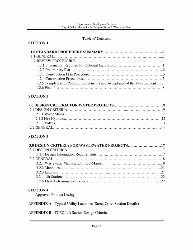
Table of Contents
SECTION 1
1.0 STANDARD PROCEDURE SUMMARY…………………….…………………..1 1.1 GENERAL…..………………………………………………….……….…………...1 1.2 REVIEW PROCEDURE.……………………………………………….…….……..1
1.2.1 Information Required for Optional Land Study……………………………….1 1.2.2 Preliminary Plat………………………………………………………………..2 1.2.3 Construction Plan Procedure…………………………………………………..3 1.2.4 Construction Procedures………………………………………………………7 1.2.5 Completion of Public Improvements and Acceptance of the Development…..7 1.2.6 Final Plat……………………………………………………………………….8 SECTION 2
2.0 DESIGN CRITERIA FOR WATER PROJECTS…………..………….………….9 2.1 DESIGN CRITERIA…………………………………….…..………..………………9
2.1.1 Water Mains……………………………………………………………………9 2.1.2 Fire Hydrants…………………………………………………………………..12
2.1.3 Valves…………………………………………..…………………...………...13 2.2 GENERAL………………………………………………………………………..…14
SECTION 3
3.0 DESIGN CRITERIA FOR WASTEWATER PROJECTS…..………….………17 3.1 DESIGN CRITERIA…………………………………….……….………..………...17
3.1.1 Design Information Requirements..…….…………………………………….17 3.2 GENERAL……………………………………………………………..…...……….18
3.2.1 Wastewater Mains and/or Sub-Mains…..…...…….…………………………..18 3.2.2 Manholes………..…………………………..……….…….……………...…..21 3.2.3 Laterals……………………………….…..………………………………...…21 3.2.4 Lift Stations……………………………………………………………..……. 22
3.2.5 Flow Determination Criteria………..…………………………….…..….…...22 SECTION 4
Approved Product Listing APPENDIX A - Typical Utility Locations (Street Cross-Section Details) APPENDIX B - TCEQ Lift Station Design Criteria
Page I
Section 1
Department of Development Services City of DeSoto Manual for the Design of Water & Wastewater Lines
1.0 STANDARD PROCEDURE SUMMARY
1.1 GENERAL
This manual contains policies and procedures for water and wastewater engineering planning and design by the City Engineering Division and by engineering firms engaged for public or private projects. Deviations from these policies and procedures will not be accepted unless approved by the Development Services office.
Standard review procedures outlined in this manual is intended to expedite the review process of engineering plans and specifications for the construction of water and wastewater facilities. It does not necessarily limit the number of times plans and specifications may be returned to the project engineer for needed changes. Also, it is not intended to limit the number of times that the project engineer may call on the Engineering Department staff for information. Plans will generally be reviewed in the order they are received.
1.2 REVIEW PROCEDURE
The procedure for approving a Plat requires a Preliminary Plat, and Final Plat. Except as otherwise permitted, the approval of a Preliminary Plat by the Planning and Zoning Commission and City Council is required for the construction of public improvements on the property. The Preliminary Plat and the associated engineering plans for the property may be amended during construction, with only major changes requiring approval by the Planning and Zoning Commission. Upon completion of the required public improvements, or the provision of an Improvement Agreement, the Owner may submit a corrected Final Plat for the Subdivision. Lots may be sold and building permits obtained after approval of the Final Plat by the Planning and Zoning Commission, and recording thereof.
1.2.1 Optional Land Study
The purpose of the Optional Land Study is to review and approve a general plan for the Development of property including the layout of streets, lots, open space sites for public facilities, and utilities. An Optional Land Study may be submitted, at the option of the Owner, prior to the submission of a Preliminary Plat.
Page 1
Department of Development Services City of DeSoto Manual for the Design of Water & Wastewater Lines
Before preparing the Optional Land Study, the applicant shall schedule an appointment and meet with the City staff to discuss the procedures for approval of the Optional Land Study and the requirements as to general layout of streets and/or reservations of land, street improvements, drainage, sewerage, fire protection, and similar matters, as well as the availability of existing services. When the Land Study is submitted for consideration to the City, the developer must submit to the Engineering Division a site plan showing the location and size of water and wastewater infrastructure necessary to serve the proposed development. The Optional Land Study shall show existing sewers, water mains, culverts, or other underground structures within the tract and immediately adjacent thereto with pipe sizes and locations indicated.
The Optional Land Study shall show proposed water, sanitary sewer and storm sewer pipelines with culverts, bridges, and other appurtenances or structures shown. Plans shall be in sufficient details to determine the feasibility of the proposed development. It is in the best interest of the project engineer and/or developer to seek comments from Development Services prior to finalizing any plat documents. Approval of the Optional Land Study by the Commission constitutes authorization by the City for the Owner to submit application for approval of a Preliminary Plat in accordance with the procedure for Preliminary Plats subject to compliance with any conditions attached to approval of the Optional Land Study.
1.2.2 Preliminary Plat
Prior to the filing of a Preliminary Plat, the Developer shall meet with the City Staff. The purpose of the meeting is to familiarize the Developer with the City’s development regulations and the relationship of the proposed Subdivision to the Comprehensive Plan.
Page 2

Department of Development Services City of DeSoto Manual for the Design of Water & Wastewater Lines
Prior to submission of a Preliminary Plat, the Developer shall submit to the City construction and engineering plans for the public infrastructure improvements required for the proposed Subdivision. After the Pre-Application Conference and completion of the engineering and construction plans for all public infrastructure improvements, the Developer shall file the required number of copies of the Preliminary Plat of the proposed subdivision with the Planning and Zoning Department. No Preliminary plat shall be approved unless the engineering and construction plans for the required public infrastructure improvements have been submitted and approved by the City Engineer.
1.2.3 Construction Plan Procedure
A. Construction plans shall be prepared by or under the supervision of a Professional Engineer registered in the State of Texas as required by state law governing such professions. Plans submitted for review by the City shall be dated and bear the responsible engineer’s name, serial number and the designation of “Professional Engineer” and an appropriate stamp or statement near the engineer’s identification, stating that the documents are for preliminary review and are not intended for construction. Final plans acceptable to the City shall bear the seal and signature of the engineer and the date signed on all sheets of the plans.
B. Three (3) sets of prints shall be submitted to the Development Services
Department. After review, a detailed letter and/or one (1) set of prints will be returned to the project engineer with errors, corrections, additions or deletions indicated. One set of plans shall be retained by the Development Services Department until final construction plans are accepted by the City.
C. The plans shall contain all necessary information for construction of the
project, including screening walls and other special features. All materials specified shall conform to the Standard Specifications and Standard Details of the City.
D. A comprehensive study of the immediate area of development and the
surrounding properties in order to evaluate the adequacy of the planned project facilities for present and future needs.
Page 3
Department of Development Services City of DeSoto Manual for the Design of Water & Wastewater Lines
E. A determination of the size of water mains required to furnish adequate water service for both immediate and ultimate conditions so that the project will be designed in accordance with the Water Distribution Master Plan.
F. Each phase of a subdivision will be analyzed on its own merit to “stand
alone”. Design requirements will include looping water mains within the development and providing all sanitary sewer improvements necessary for each phase of a development to function independently of a future phase of the development. Similar requirements are found in the Paving Manual for streets and alleys.
G. With all wastewater projects, the entire drainage basins shall be considered
for any particular project. The wastewater collection system shall be sized to meet ultimate built-out conditions (based on current zoning and the Wastewater Collection Master Plan) and shall include connections for upstream developments. The size and complexity of the design will determine the amount of information needed to be supplied in the preliminary design.
H. The design shall include the general configuration of the water and
wastewater main layout along minor residential and collector streets as shown in Section 4.
I. Design shall include fire hydrant coverage.
J. Existing infrastructure such as: pavement, curbs, gutters, driveways, drainage
structures, utilities, fire hydrants, and buildings (in or adjacent to the proposed improvements), shall be clearly located in the construction plans.
K. Plan and profile sheets shall clearly identify all existing and proposed
infrastructure in sufficient detail to avoid underground conflicts.
L. Temporary Construction and Permanent Easements shall be delineated on the plans, including affected property owner’s name and the easement reference
designation in the project specifications.
Page 4

Department of Development Services City of DeSoto Manual for the Design of Water & Wastewater Lines
M. Easements not shown on a plat shall be procured by separate instrument. The
procurement of any easement is the responsibility of the developer or property owner. The metes and bounds description of the easement shall be submitted to the Engineering Division, which will review the easement for accuracy. A copy of the off-site easement shall be included in the construction plan (preferably behind the plat page).
N. After owner’s signature and acknowledgment, the developer shall file the
easement and provide City with recorded copy. When the easement has been recorded at the Dallas County Courthouse and a volume and page assigned, the original easement will be kept at the Planning and Zoning Department and City Secretary’s office.
O. All utilities, including pipe line, underground cables, power, telephone or
telegraph poles, meter boxes, etc., shall be clearly located in all proposed and existing dedications to contain water and waste water utilities. Any damage to said features shall be the responsibility of the contractor for repair and/or replacement.
P. Street names, rights-of-way and pavement widths, types of surfacing, curbs
and proposed curbs shall be shown where pertinent to the proposed water and wastewater utilities.
Q. Notes to reconstruct streets, fences, block sod replacement, etc. that are
affected by design should be shown.
R. Notes pertinent to connections with existing water and wastewater utilities shall be included.
S. A north arrow shall be shown on each plan view. T. The use of “off-standard” scales will not be permitted. A site plan shall be
drawn to scale of 1" = 60'. In the use of plan and profile sheets, the scales shall be drawn to 1" = 50' H, 1" = 5' V or 1" = 40'H, 1" = 4'V.
U. Topography notation should be included as necessary for clarification of
design.
V. Existing and proposed surface grades shall be shown and labeled.
Page 5

Department of Development Services City of DeSoto Manual for the Design of Water & Wastewater Lines
W. Label all wastewater grade lines and profiles. Show datum elevations and
floor plan as often as necessary for clarification.
X. On-site water and wastewater may be displayed together on one layout sheet. On-site wastewater profiles may be shown on separate profile sheets, indexed by line numbers on the layout sheet.
Y. Plans must be signed and sealed by the Professional Engineer, licensed in the
State of Texas, who is responsible for the design.
Z. Construction details shall be in accordance with the City’s Construction Detail Sheets. If not reflected in the City’s Construction Detail Sheets, the Standard Specifications and Detail for Public Works Construction by NCTCOG will be used.
AA. All permits and fees necessary for construction (Construction Inspection Fee, SWPPP, TCEQ, etc.) shall be the responsibility of the developer or contractor.
BB. All water and wastewater utilities shall be required to extend across the full
width of the last lot platted on each street proposed within the Subdivision, in such an alignment that it can be extended to the next property in accordance with the Master Water and Sewer Plans for the City. Properties already served by water and sewer shall not be required to install additional facilities unless the current lines are not of adequate capacity to serve the proposed Development, in which case the Developer shall be required to install adequate facilities.
CC. Every lot of the Plat shall have direct access to the water and sewer system.
Utility service shall be from a water/wastewater main located in an abutting right-of-way or through easements from the lot to a water/sewer main.
DD. No water main shall be extended unless the diameter of any such extended main is a minimum of eight (8") inches in diameter. Larger mains may be required per the Water Master Plan.
EE. No wastewater main shall be extended unless the diameter of such extended
main is a minimum of six (6") inches in diameter. Larger mains may be required per the Wastewater Master Plan.
Page 6
Department of Development Services City of DeSoto Manual for the Design of Water & Wastewater Lines 1.2.4 Construction Procedures
A. Construction plans and specifications must be in complete and correct form. Only those plans with the “Approved for Construction” stamp will be recognized.
B. Pre-construction Conference. The City Engineer may require that all
contractors participating in the construction meet for a pre-construction conference to discuss the project prior to release of a permit.
C. All contractors participating in the construction shall be provided, at the
Developer’s cost, with a set of approved plans bearing the stamp of release of the Engineering Department. One set of these plans shall remain at the job site at all times.
D. All applicable fees must be paid to the City.
1.2.5 Completion of Public Improvements and Acceptance of the Development
A. Construction inspection shall be supervised by the City Engineer. Construction shall be in accordance with the approved Plans and the Design Standards.
B. A final walk-thru inspection is required for each project. The contractor
and/or developer shall correct all deficiencies noted prior to final acceptance by the City.
C. The City will not accept dedication of required public improvements until
the applicant’s engineer has certified to the City Engineer, through submission of Record Drawings, indicating location, dimensions, materials, and other information required by the Commission or City Engineer, that all required public improvements have been completed. The Record Drawings shall also include a complete set of drawings of the paving, drainage, water, sanitary sewer, or other public improvements.
Page 7
Department of Development Services City of DeSoto Manual for the Design of Water & Wastewater Lines
D. Prior to acceptance, the project engineer shall provide the City Record
Drawings for the project. The following documents shall be submitted: one (1) set of mylar, two (2) sets of blue or black line prints, and one digital copy (.dxf format) of the Record Drawings. Raster files and other file formats are not acceptable. All files shall be submitted on CD-ROM in CD-R.
E. A maintenance bond in accordance with City Ordinances will also be
required prior to the City issuing a Letter of Acceptance. F. Upon acceptance of the required public improvements, the City Engineer
shall submit a Letter of Acceptance to the Developer stating that all required public improvements have been satisfactorily completed.
G. Upon completion of construction and the submittal of the documents
referenced above, the Engineering Division will recommend to the Planning and Zoning Department to accept the application for Final Plat.
1.2.6 Final Plat
After approval of the Preliminary Plat by the Planning and Zoning Commission and the City Council and upon completion of the public improvements, the Owner shall submit a Final Plat of the property for approval.
Page 8
Section 2
Department of Development Services City of DeSoto Manual for the Design of Water & Wastewater Lines
2.0 DESIGN CRITERIA FOR WATER PROJECTS
2.1 DESIGN CRITERIA
The following design criteria shall be used for water main design within the City of DeSoto. Since all projects are unique, any design criteria not included in this document shall be at the discretion of the City Engineer. 2.1.1 Water Mains
A. The minimum size main shall be eight inches (8") in residential, twelve inches
(12") for non-residential. Larger main size may be required by the Water Distribution Master Plan or to meet fire protection needs as determined by analysis. The City will pay for the increment of cost of water mains over eighteen inches (18") in diameter provided that such mains are required as a part of the City’s Water Distribution Master Plan.
B. The minimum residential water service line shall be one-inch (1")
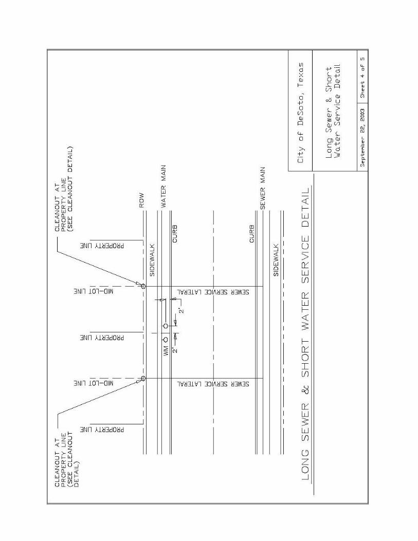
polyethylene and shall be installed behind back of curb in parkway and away from driveways, as shown in Appendix A.
C. The standard location of water mains for minor residential and collector
streets shall be as shown in Appendix A.
D. There shall be a minimum fifteen feet (15') easement required for water mains.
E. When both water and wastewater are to be located in the same easement, the minimum width of easement shall be twenty feet (20'). Two feet (2') of easement width shall be added for every foot deeper than ten feet (10') in depth.
Page 9
Department of Development Services City of DeSoto Manual for the Design of Water & Wastewater Lines
F. All water mains shall meet the requirements of AWWA and NCTCOG under
the following specifications:
Pipe Diameter
NCTCOG Item
AWWA Standard Description
1" to 2" Service Lines
2.12.26 C901 DR9 DIP Pipe O.D.
High Density Polyethylene
6" to 12"
2.12.20 C900 DR14
PVC
Greater than 12"
2.12.5 C301 C303
Reinforced Concrete Cylinder Pipe
2.12.20 C905 DR18 PVC 2.12.8 C151 Class 50 Ductile Iron Pipe
G. Where a proposed or existing water main crosses proposed or existing storm sewer and the water main is less than two feet (2') below flow line of the storm sewer, the water main shall be concrete encased a minimum of five feet (5') each way from centerline of storm sewer.
H. Where proposed or existing water mains cross proposed or existing
wastewater mains, the wastewater main should be concrete encased nine feet (9') either side of the crossing. Two feet (2') minimum vertical clearance is also required.
I. Proposed water main shall not be closer than nine feet (9') to a parallel
wastewater. Proposed water main can be as close as four feet (4'), if the water main is a minimum of two feet (2') higher than the wastewater main.
J. A profile of the existing ground surface and elevation of the pipe shall be
shown on the plans for water mains twelve inches (12") and larger, or as required by the City.
K. A minimum of one foot (1') clearance (horizontal or vertical at the discretion
of the City Engineer) shall be required between proposed water mains and proposed curb inlets (including stub-outs from the rear of inlets).
Page 10
Department of Development Services City of DeSoto Manual for the Design of Water & Wastewater Lines
L. Tracer tape is to be installed along the major axis of all non-metallic water
pipes one foot (1') above top of pipe. The tape is to be two inches (2") wide, consisting of a metal strip coated with a corrosion resistant substance. The tape must be detectable by a metal detection device to a minimum depth of four feet (4'). The tape shall be two inches (2") wide ALARMALINE or approved equal.
M. Water meters are to be located in the parkway two feet (2') from back of curb.
N. Dead-end mains shall not exceed six hundred feet (600') unless cul-d-sac
length has been mitigated or a longer dead-end section has been approved (ie: development site restrictions) by the City Engineer. Provisions shall be provided for flushing dead-end mains, such as through a fire hydrant placed near the terminal end of the main.
O. Mains not meeting the criteria in Section 2.1.1 Paragraph "N", regardless of
length, shall be looped to a secondary source of feed to prevent total loss of service to development during maintenance procedures.
P. There shall be a minimum cover of five feet (5') in public rights-of-way where
there is no curb and gutter on the street. In general, the minimum cover below the top of the street subgrade should be as follows:
Pipe Diameter Min. Cover
8" 4.0' 12" 5.0' 16" 5.5'
Larger than 16" min. 6.0' Q. The minimum radius to be used for P.V.C. water pipe is as follows:
Pipe Diameter Minimum Allowable Radius 8" 200'
10" 250' 12" 300'
Greater than 12" (300D)* *D = Pipe Diameter in feet
Page 11
Department of Development Services City of DeSoto Manual for the Design of Water & Wastewater Lines
2.1.2 Fire Hydrants
A. In residential areas, except apartments and condominiums, fire hydrants shall be spaced a maximum of four hundred feet (400') apart. In non-residential areas, including multifamily, fire hydrants shall be spaced a maximum of three hundred (300') apart.
B. In commercial areas, including apartments and condominiums, streets longer than three hundred feet (300') which end in cul-de-sacs must have a fire hydrant in the cul-de-sac. Cul-de-sacs three hundred feet (300') or less from the center of connecting street intersection must be served by a fire hydrant located at the cul-de-sac side of the connecting street intersection.
C. In residential areas, except for apartments and condominiums, streets longer than four hundred feet (400') which end in cul-de-sacs must have a fire hydrant in the cul-de-sac. Cul-de-sacs four hundred feet (400') or less from the center of connecting street intersection must be served by a fire hydrant located at the connecting street intersection.
D. If a fire hydrant is required in cul-de-sac, a minimum eight inch (8") main
shall be provided up to the fire hydrant.
E. Fire Hydrants shall be required at all street intersections.
F. The normal and maximum depths of bury for fire hydrants are four feet (4') and six feet (6'), respectively. Offsets or bends shall be used if the main is deeper than six feet (6') to bring fire hydrant to maximum six foot (6') depth.
G. Final fire hydrant location subject to approval by City Fire Inspector. H. No fire hydrant shall be placed closer than nine feet (9') from a wastewater
main.
I. All fire hydrants shall be installed at least two feet (2'), but less than six feet (6'), from the back of the curb of a paved street or edge of a designated approved fire lane. Fire hydrants shall be located within parkways and not in the sidewalk.
Page 12
Department of Development Services City of DeSoto Manual for the Design of Water & Wastewater Lines
J. Fire hydrants may be alternated from one side of the street to the other on divided thoroughfare per direction of the DeSoto Fire Department. Eight (8") feeder mains shall be required for fire hydrants located in Right-of-Way opposite of the water main.
K. A Blue Reflective Hydrant Marker(s) shall be installed on the street(s) pavement to indicate the presence of the fire hydrant.
L. Only national standard three-way hydrants with a 4" pumper nozzle and 2 each 2½" hose nozzles are approved.
M. All hydrant threads shall match those in use by the DeSoto Fire Department.
N. All fire hydrant leads shall contain a gate valve.
O. Fire flow requirements on certain projects will be determined by the DeSoto
Fire Department. Fire flow and hydrant locations shall be determined by type of construction and building occupancy as described in the City of DeSoto Building Code.
2.1.3 Valves
A. Valves twelve inches (12") and under will be Gate Valves meeting the requirements of AWWA C500 or AWWA C509 (NCTCOG Item 2.13.1). Butterfly valves shall be used on all water mains fourteen inches (14") in diameter and greater meeting the requirements of AWWA C504 (NCTCOG Item 2.13.4).
B. Each water main shall be designed with valves located in such a manner as to
enable initial sterilization and testing after construction and to enable repairs to pipe with a minimum interruption to customer service. In general, no more than four (4) valves should be used to isolate a segment of water line.
Page 13

Department of Development Services City of DeSoto Manual for the Design of Water & Wastewater Lines
C. Valves 12-inch and under shall be placed on or near property corners not to
exceed 800 feet apart in residential, duplex and apartment districts and not over 500 feet apart in all other districts: and in such a manner as to require preferably two, but not more than three valves to shut down each City block, or as may be required to prevent shutting off more than one fire hydrant. On cross-feed mains without services, a maximum of four valves shall be used to shut down each block. Also, valves shall be placed at or near the ends of mains in such manner that a shut down can be made for a future main extension or future repairs without causing loss of service on the existing main.
A. Valve stem extensions shall be required for any valve that the operating nut is
located in excess of 4 feet below the top of valve box. This extension shall be sufficient length to insure that the top is within 4 feet of the valve box lid. Valve locations shall be permanently marked on face of street curb.
2.2 GENERAL
2.2.1 Water Services:
Minimum service line diameter shall be one inch (1"). Service lines with a diameter of one (1) to two (2) inches shall be polyethylene DR-9. Service lines with a diameter larger than two inches (2") shall be C-151 D.I., or C-900 PVC. All lots shall require a separate dedicated service line from the main. Bullhead or multiple connections to a single service line shall not be allowed. Where multiple connections are required, such as multi-family or commercial, a sub-main (size to be approved by the City Engineer) shall be constructed for that purpose. Metered irrigation systems shall require a separate service line. Minimum depth for service laterals under street paving shall be two feet below top of subgrade. Depth of angle stop shall be a minimum of nine inches (9") to a maximum of twelve inches (12") below meter box lid. A meter box shall be installed with each service. Water service locations shall be permanently marked on face of street curb.
2.2.2 Boring Requirements: No street shall be open cut without prior approval from the City Engineer. All water mains shall be cased. P.V.C. shall be steel cased (with approved spacers) and grouted at each end. Ductile iron pipe shall be grouted from end to end. Borings limits shall be a minimum of two feet (2') from back of curb. Bore pit backfill shall be compacted to 90% (max. lifts of six (6) inches). R-O-W permitting shall be required before boring and provide applicable traffic warning devices in accordance with the most current edition of the Texas Manual on Uniform Traffic Control Devices (Texas MUTCD).
Page 14
Department of Development Service City of DeSoto Manual for the Design of Water & Wastewater Lines
2.2.3 Pressure Regulators:
In low areas where pressures may exceed 100 p.s.i., builders and plumbers should be advised that in such locations, pressure reducing devices should be installed as part of the plumbing on the customer maintained service line.
2.2.4 Air and Vacuum Relief:
Air and vacuum relief valves shall be installed in high points along transmission mains to exhaust trapped air and to relieve vacuums from the system. On distribution mains, fire hydrants, where applicable, can be located at high points in lieu of air and vacuum relief valves.
2.2.5 Blow-Off Valves:
In low points along transmission mains, blow off valves shall be required in the system to drain the mains. On distribution mains, fire hydrants, where applicable, can be located at low points in lieu of blow off valves.
2.2.6 Clean Out Wyes:
In strategic locations along lateral mains, feeder mains, transmission mains, etc., cleaning wyes may be provided for passing “Polly Pigs” through to sweep trash and debris from the pipe. These shall be supplemented with chlorination and sampling points, as required for the proper sterilization of the main. Locations for these wyes will be determined through conference with the City staff.
2.2.7 Quick Closing Valves:
Quick closing valves will not be permitted in any water facility connected to the City of DeSoto Water System.
2.2.8 Backflow Device Requirements: Approved double check valve or double check valve w/ detector check (depending on application of line) on private property at the R.O.W. line for looping water line on private property (i.e. private mains, mains with fire hydrants, or fire sprinkler systems) shall be required. The size of the valve shall be the same size of the main as required by the City of DeSoto Fire Marshall. Reduced size detector check valves shall not be approved.
Page 15

Department of Development Service City of DeSoto Manual for the Design of Water & Wastewater Lines
The following is approved as the usual Standard Design Criteria for all improvements for DeSoto Water System. These values are subject to adjustment to meet unusual project requirements. • Average Day Water Use: 215 Gallons Per Capita per Day (GPCD). • Maximum Day: for Maximum Day unrestricted use – Multiply the annual average
day by 2.25. • Maximum Hour: for Maximum Hour unrestricted use – Multiply the Maximum Day
by 2.0. • Persons per Residential Connection: 3.5. • Water Mains shall be sized to: meet Maximum Hour or Maximum Day + Fire Flow
requirements, whichever is greater. • Fire Flow should be rated at: 1,000 gpm in residential areas. • Computation:
Maximum Day/Connection = (2.25) (215) (3.5) = 0.00169 mgd
1,000,000 Maximum Hour/Connection = (2.00) (0.00169) = 0.00338 mgd • Pipe Class vs. Pressure: Refer to the General Contract Documents and General Specifications.
• Minimum Working Pressure: In residential areas, the working pressure in mains shall not be less than 45 p.s.i., except in isolated high elevation areas where the pressure shall not be less than 35 p.s.i.
Page 16

Section 3
Department of Development Services City of DeSoto Manual for the Design of Water & Wastewater Lines
3.0 DESIGN CRITERIA FOR WASTEWATER PROJECTS
3.1 DESIGN CRITERIA
The following design criteria shall be used for wastewater design within the City of DeSoto. Since all projects are unique, any design consideration not included in this document shall be at the discretion of the City Engineer.
3.1.1 Design Information Requirements
A. Prepare a survey of the proposed main location. This survey shall include:
1. Plan survey showing relation between property corners and proposed
wastewater main centerline; this information to be in sufficient detail to properly locate the proposed main and determine the number of properties involved for securing the necessary easements.
2. Directional flow arrows shall be shown on plan view. 3. Profile survey showing:
• Field-determined elevation of any existing manhole invert,
stub-out or wastewater main to which the proposed wastewater main is to connect or provide data to support proposed plan.
• Elevation of any draw, creek, depression, pond, lake or water
course within three hundred feet (300') of any portion of centerline at intervals not to exceed one hundred feet (100'), with proper reference made as to location with respect to centerline.
• Elevation of stub out of each existing house or building to be
served directly by the main if available. In case a stub out is not available, ground or finished floor elevations should be shown at the front and back of the house. In any event, care should be taken to properly locate the existing house and points of elevation taken with relation to centerline.
Page 17
Department of Development Services City of DeSoto Manual for the Design of Water & Wastewater Lines
(B) Prepare plan and profile drawings for the mains showing the information obtained from the survey.
1. Station 0+00 of the proposed main shall be equated to the interceptor main Station at the point of connection, if possible.
2. The plot of the main on the profile sheet shall be from left to right,
beginning at Station 0+00 (lowest flow line elevation), and progressing right in increasing stations to the highest flow line elevation.
(C) Analyze the data obtained in the foregoing steps. Determine the points
where each increment of load will be added to the proposed main and prepare a tabulation showing the estimated magnitude of the population load under ultimate conditions at each of those points, showing both the incremental and cumulative load.
(D) Wastewater mains shall be designed and constructed in accordance with
the Wastewater Collection Master Plan for the City of DeSoto. (E) All existing water, sewer, gas, storm sewer, telephone, power, and other
utilities parallel to or crossing the proposed wastewater main shall be adequately designated as to size, type, and location.
(F) Benchmarks used shall be clearly referenced, giving the descriptive
locations and elevations. 3.2 GENERAL
3.2.1 Wastewater Collection Mains and/or Sub-Mains
(A) The standard location of the wastewater line for minor residential and collector streets shall be as indicated in Appendix A.
(B) Where topography requires that a wastewater main be installed with less
cover than 3.5 feet to finished grade, pipe shall be concrete encased per direction of the City Engineer.
Page 18

Department of Development Services City of DeSoto Manual for the Design of Water & Wastewater Lines
(C) Where proposed or existing water mains cross proposed or existing
wastewater mains, the wastewater main shall be concrete encased or water tight pipe used nine feet (9') each way from centerline of the crossing and two feet (2') vertical clearance maintained.
(D) Where proposed or existing wastewater mains cross proposed or existing
storm sewer and the wastewater main is less than three feet (3') below flow line of the storm sewer, the wastewater main shall be concrete encased a minimum of five feet (5' ) each way from centerline of the storm sewer.
(E) Wastewater mains material shall be as specified in the material listing
presented in Section 4 (Approved Product Listing – Water and Wastewater Systems). Wastewater mains at a depth of more than ten feet (10') shall be SDR-26.
(F) Pipes should be placed on such a grade that the velocity when flowing full is not less than 2-feet or more than 6-feet per second. The minimum and maximum grades for pipes flowing full shall be as follows:
Pipe
Diameter Min. Slope Max. Slope
6" 0.50% 12.35% 8" 0.33% 8.40%
10" 0.25% 6.23% 12" 0.20% 4.88% 15" 0.15% 3.62% 18" 0.11% 2.83% 21" 0.09% 2.30% 24" 0.08% 1.93% 27" 0.06% 1.65%
Using the Manning’s formula, the minimum acceptable “n” for design and construction shall be 0.013 for PVC pipe. The “n” used takes into consideration the slime, grit, and grease layers that will affect hydraulics or hinder flow as the pipe matures.
(G) The minimum horizontal spacing between wastewater mains and water
Mains shall be nine feet (9').
Page 19

Department of Development Services City of DeSoto Manual for the Design of Water & Wastewater Lines
(H) Project requirements shall contain requirements for the Water Department television camera equipment to be installed or removed at the end of all wastewater mains. In some instances, this may require that a manhole be placed at the end of the wastewater main for that and other maintenance purposes. A manhole or clean-out shall be placed at all ends. (I) Consider the following requirements to determine the grade:
1. If the wastewater collection main is parallel to a drainage course, the collection main shall not be less than two feet (2') below bottom of the channel.
2. The wastewater collection main shall be far enough below the bottom of such drainage course to permit a four inch (4") service line to pass under the drainage course with one foot (1') of cover, approach the proposed main on at least a 2.00% grade, and match tops with the proposed main at the point of connection.
3. Wastewater mains shall not be less than three and one-half feet (3.5') below the finished grade of the street in which it is to be located.
(J) Minimum width of easement for wastewater mains shall be fifteen feet (15'). (K) When a wastewater main is to be constructed deeper than ten feet (10') below surface, the easement width shall be a minimum of twenty feet (20'). The width of easement should be increased as the depth of the main increases based on a side slope of one horizontal to one vertical (1:1) for each side of the trench.
(L) In the event a wastewater main exceeds a depth of 15', a parallel sub-main shall be constructed at a more reasonable depth which will service the laterals to the adjacent properties. Trunk mains with no laterals may be installed at depths greater than 15 feet, however, pipe must meet SDR-26 specifications. (M) When the slope of a wastewater main changes, a manhole shall be required.
No vertical curves will be allowed. Minimum radius for horizontal curves (pulling pipe, not joints) shall be 200 feet.
(N) A manhole shall be required for all wastewater connections 6" or larger.
Page 20
Department of Development Services City of DeSoto Manual for the Design of Water & Wastewater Lines
(O) Profile sheets shall show flow capacity (Qcap), design velocity (Vdesign), design capacity (Qdesign), type of pipe, and grade between manholes.
3.2.2 Manholes (A) Locate manholes a maximum of five hundred feet (500') apart on
wastewater mains.
(B) On dead end wastewater mains, a manhole at the end of the main shall be installed if main is two hundred feet (200') or more. On mains less than two hundred feet (200'), a clean-out shall be installed at the end of main.
(C) Provide manholes on wastewater mains sizes 6 to 12 inches when horizontal
angles are greater than five degrees (5°). Maximum deflection per joint shall not exceed manufacturers specifications.
(D) Ring sizes for manholes shall be thirty inches (30"). The diameter of a manhole constructed over the center of a wastewater collection main shall vary with the size of the wastewater collection system. For 6" and 8" collection mains, the manhole shall be 4.0 foot minimum diameter; for 10", 12", and 15" mains – 5.0 foot minimum diameter; 18" mains and larger – 6.0 foot minimum diameter. Manhole and cleanout locations shall be permanently marked on face of street curb.
(E) Inside drop manholes shall be required when connection to a manhole exceeds two feet vertical distance from connection flowline to manhole flowline.
(F) Areas subjected to flooding require special consideration to minimize
inflow. Sealed manhole covers shall be required in all flood prone and/or drainage areas.
3.2.3 Laterals
(A) The design of wastewater collection laterals follows the same basic design
procedures as those outlined for mains and sub-mains. In general, for single family dwellings, the lateral size shall be 4" minimum; for multiple units, apartments, local retail and commercial – 6" minimum; for manufacturing and industrial, the size should be 8" or larger as required.
Page 21

Department of Development Services City of DeSoto Manual for the Design of Water & Wastewater Lines
(B) All wastewater collection laterals shall be installed at the centerline of the lot as shown in Appendix A. All wastewater collection laterals shall have
property line clean outs installed. Wastewater service lateral locations shall be permanently marked on face of street curb.
(C) Laterals 6" and larger shall require construction of a manhole at connection
to the main, or if available, connection to an existing manhole.
(D) All service laterals shall be SDR-26 pipe.
3.2.4 Lift Stations (A) Lift station design shall be in full conformance to TCEQ Regulations, latest revision. Letter of approval from the TCEQ shall be provided at the time of preliminary engineering plan submittal. Flows shall be as calculated by this manual.
(B) The current rules can be obtained at: www.tceq.state.tx.us/oprd
(C) Copy of April 15, 1990, 15 Tex Reg. 1801 is shown in Appendix “B”.
3.2.5 Flow Determination Criteria
(A) Using the cumulative population load at each point of load increment, determine the load on the section below that point in GPM using (reference K-E-F, Inc. Study 1987):
(1) Average Load per person per day = 125 gal.
(2) Average Load per person + 125/1440 = 0.0868 GPM
(3) Q Average – Average Load of a given population
(0.0868) x (population) = GPM
(4) Peaking Factor calculated using Harmon’s coefficient
M = 1 + 14 (Harmon’s Formula) 4 + (P)1/2
Where: P = Population in thousands M = Ratio of Peak Load to Average Load
Page 22
Department of Development Services City of DeSoto Manual for the Design of Water & Wastewater Lines
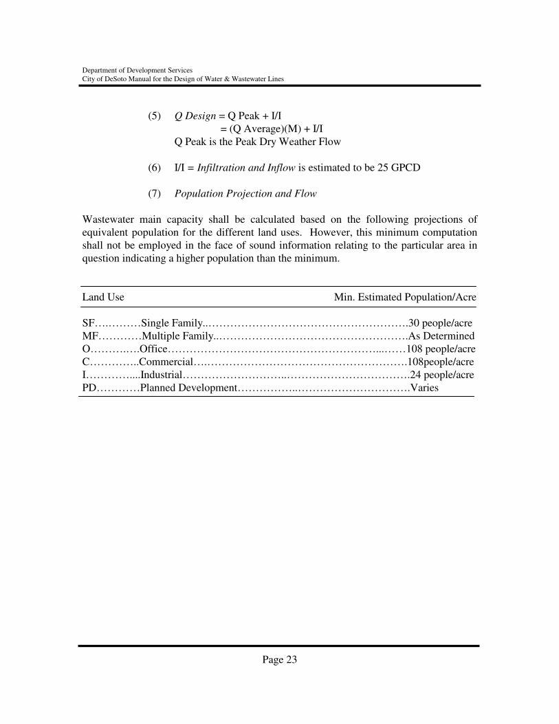
(5) Q Design = Q Peak + I/I = (Q Average)(M) + I/I
Q Peak is the Peak Dry Weather Flow (6) I/I = Infiltration and Inflow is estimated to be 25 GPCD
(7) Population Projection and Flow
Wastewater main capacity shall be calculated based on the following projections of equivalent population for the different land uses. However, this minimum computation shall not be employed in the face of sound information relating to the particular area in question indicating a higher population than the minimum. Land Use Min. Estimated Population/Acre SF….………Single Family..……………………………………………….30 people/acre MF…………Multiple Family..…………………………………………….As Determined O……….….Office…………………………………………………...……108 people/acre C…………..Commercial….……………………………………………….108people/acre I…………....Industrial………………………..…………………………….24 people/acre PD…………Planned Development……………..………………………….Varies
Page 23

Section 4

APPROVED PRODUCTS LISTING - WATER AND WASTEWATER SYSTEMS
CITY OF DESOTO, TEXAS
PRODUCT: BOLTS, COR-TEN SIZE REFERENCE SPECS MAKES APPROVED MODIFICATION REQUIRED AWWA C111 1. NSS None
PRODUCT: BOLTS, DUCTILE SIZE REFERENCE SPECS MAKES APPROVED MODIFICATION REQUIRED AWWA C111 1. Ductile Durobolt 2. Ductile 3. Flangeloc 4. Durablot
PRODUCT: CLAMPS, FULL CIRCLE REPAIR SIZE REFERENCE SPECS MAKES APPROVED MODIFICATION REQUIRED 4" to 12" City Specifications 1. Ford None
2. Smith-Blair 3. Superior
12" to 24" 4. Ford
5. Smith-Blair 6. Superior
PRODUCT: CLAMPS, EXTENDED RANGE REPAIR SIZE REFERENCE SPECS MAKES APPROVED MODIFICATION REQUIRED 4" to 14" City Specifications 1. Smith-Blair None (All clamps must be 2. Romac type 304 stainless steel) 3. Ford 4. Superior

PRODUCT: CLAMPS, SPLIT CIRCLE REPAIR SIZE REFERENCE SPECS MAKES APPROVED MODIFICATION REQUIRED ¾" to 3" AWWA & City 1. Smith-Blair None Specifications 2. Romac 3. Ford
4. Superior
PRODUCT: COATINGS (CONCRETE EXTERIOR) SIZE REFERENCE SPECS MAKES APPROVED MODIFICATIONS REQUIRED N/A City Specifications 1. Thorocoat None 2. Tenemecrete PRODUCT: COATINGS (STEEL EXTERIOR) SIZE REFERENCES SPECS MAKES APPROVED MODIFICATIONS REQUIRED Water tank Water Tank AWWA 1. Tenemec: None Exterior D102 & City Primer 37-77 Specifications Topcoat 23 series 3 coat alkyd system 2. Valspar: Primer 78-D-7
Topcoat 78-W-3 3. Acro: Primer 4460
Topcoat 4460 4. Kop-Coat:
340 Primer B. Kop-Coat Super
Hi-Gard C. Cook
Primer 920 W 965 D. American
Primer 395 Topcoat 395
E. Sherwin Williams Primer B62WA7 (gray) Topcoat B62 WW7
Aerial Casing Interior-Liquid Epoxy 1. Valspar None (steel) AWWA C – 210 2. Sherwin Williams Exterior- 3 coat
Alkyd system

PRODUCT: FIRE HYDRANTS SIZE REFERENCE SPECS MAKES APPROVED MODIFICATIONS REQUIRED 5 ¼" AWWA C502 & 1. Mueller 1 thru 7. Exterior Paint, 2 coats City Specifications Centurion A423 Sherwin Williams 4" Pumper Nozzle 2. Waterous WB 67 Industrial White
3. AVK 2780 Enamel 4. Guardian
5. M&H 929 (5) Epoxy coating inside shoe 6. Clow Medallion 7. American Darling
B-84B PRODUCT: FIRE HYDRANT – VALVE SEATS SIZE REFERENCE SPECS MAKES APPROVED MODIFICATIONS REQUIRED
1. Polyvalve None 2. Manufacture’s
Standard
PRODUCT: FIRE HYDRANT MARKERS (Blue w/blue reflective) SIZE REFERENCE SPECS MAKES APPROVED MODIFICATIONS REQUIRED 4"X4"X.680" Reflective Area: Ray-O-Lite, or equal. Adhesive: E-Bond 590 Hi-Mod 3.25 sq. in. Gel ASTM-C-881 Type I & IV, Grade 3, Class B & C
PRODUCT: FITTINGS, ANCHORED SIZE REFERENCE SPECS MAKES APPROVED MODIFICATIONS REQUIRED 4" to 12" AWWA C153/ 1. GRADELOK None ANSI A 21.53, AWWA C104 ANSI A21.4
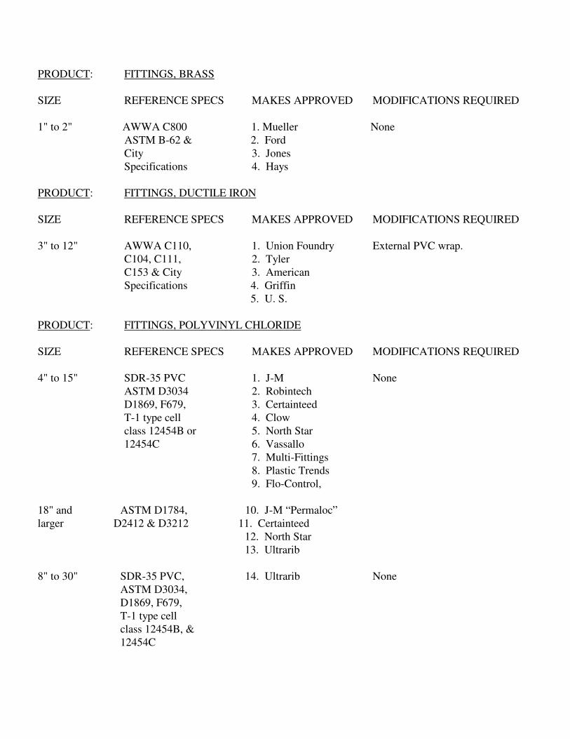
PRODUCT: FITTINGS, BRASS SIZE REFERENCE SPECS MAKES APPROVED MODIFICATIONS REQUIRED 1" to 2" AWWA C800 1. Mueller None ASTM B-62 & 2. Ford City 3. Jones Specifications 4. Hays PRODUCT: FITTINGS, DUCTILE IRON SIZE REFERENCE SPECS MAKES APPROVED MODIFICATIONS REQUIRED 3" to 12" AWWA C110, 1. Union Foundry External PVC wrap. C104, C111, 2. Tyler C153 & City 3. American Specifications 4. Griffin 5. U. S.
PRODUCT: FITTINGS, POLYVINYL CHLORIDE SIZE REFERENCE SPECS MAKES APPROVED MODIFICATIONS REQUIRED 4" to 15" SDR-35 PVC 1. J-M None ASTM D3034 2. Robintech D1869, F679, 3. Certainteed T-1 type cell 4. Clow class 12454B or 5. North Star 12454C 6. Vassallo
7. Multi-Fittings 8. Plastic Trends 9. Flo-Control,
18" and ASTM D1784, 10. J-M “Permaloc” larger D2412 & D3212 11. Certainteed
12. North Star 13. Ultrarib
8" to 30" SDR-35 PVC, 14. Ultrarib None ASTM D3034, D1869, F679, T-1 type cell
class 12454B, & 12454C
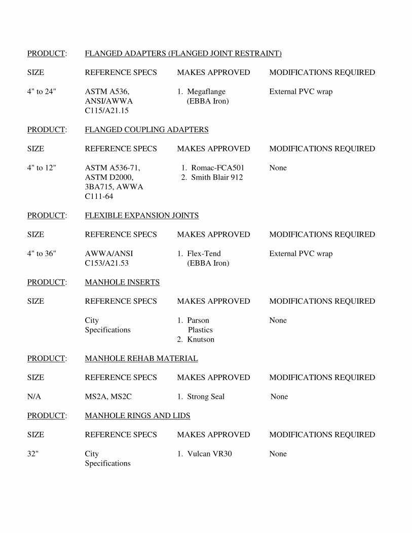
PRODUCT: FLANGED ADAPTERS (FLANGED JOINT RESTRAINT) SIZE REFERENCE SPECS MAKES APPROVED MODIFICATIONS REQUIRED 4" to 24" ASTM A536, 1. Megaflange External PVC wrap ANSI/AWWA (EBBA Iron) C115/A21.15 PRODUCT: FLANGED COUPLING ADAPTERS SIZE REFERENCE SPECS MAKES APPROVED MODIFICATIONS REQUIRED 4" to 12" ASTM A536-71, 1. Romac-FCA501 None ASTM D2000, 2. Smith Blair 912 3BA715, AWWA C111-64 PRODUCT: FLEXIBLE EXPANSION JOINTS SIZE REFERENCE SPECS MAKES APPROVED MODIFICATIONS REQUIRED 4" to 36" AWWA/ANSI 1. Flex-Tend External PVC wrap C153/A21.53 (EBBA Iron) PRODUCT: MANHOLE INSERTS SIZE REFERENCE SPECS MAKES APPROVED MODIFICATIONS REQUIRED
City 1. Parson None Specifications Plastics
2. Knutson
PRODUCT: MANHOLE REHAB MATERIAL SIZE REFERENCE SPECS MAKES APPROVED MODIFICATIONS REQUIRED N/A MS2A, MS2C 1. Strong Seal None PRODUCT: MANHOLE RINGS AND LIDS SIZE REFERENCE SPECS MAKES APPROVED MODIFICATIONS REQUIRED 32" City 1. Vulcan VR30 None Specifications

PRODUCT: MANHOLES (PRECAST CONCRETE) SIZE REFERENCE SPECS MAKES APPROVED MODIFICATIONS REQUIRED 4' dia ASTM C-76 or 1. Gifford-Hill For 30" Ring-Cover & larger C-478 & City 2. Hydro Conduit Specifications 3. Sherman Concrete Prod.
4. American Industrial pre-cast products
PRODUCT: PIPE, WASTEWATER SIZE REFERENCE SPECS MAKES APPROVED MODIFICATIONS REQUIRED 4" to 15" SDR-26 PVC, 1. J-M None ASTM D2241, Class 160 PVC 4" to 15" SDR-35 PVC, 2. J-M None ASTM D3034, 3. Certainteed & D1869 4. Hunter 5. Diamond 6. Cresline 7. ETI 8. CAN-TEX 9. NAPCO 8" to 30" SDR-35 PVC, 10. Ultra-Rib None ASTM D3034, D1869 & F794 21" to 48" ASTM D1784 11. Lamson Carton Vylon Large Dia. Wastewater Pipe 18" ASTM D1784, 12. J-M “Permaloc” D2412, F679, 13. Certainteed T-1 type cell class 12454B or 12454C 8" > AWWA C151 1. US Pipe External PVC wrap Class 50 D.I. 2. American 3. Tyler
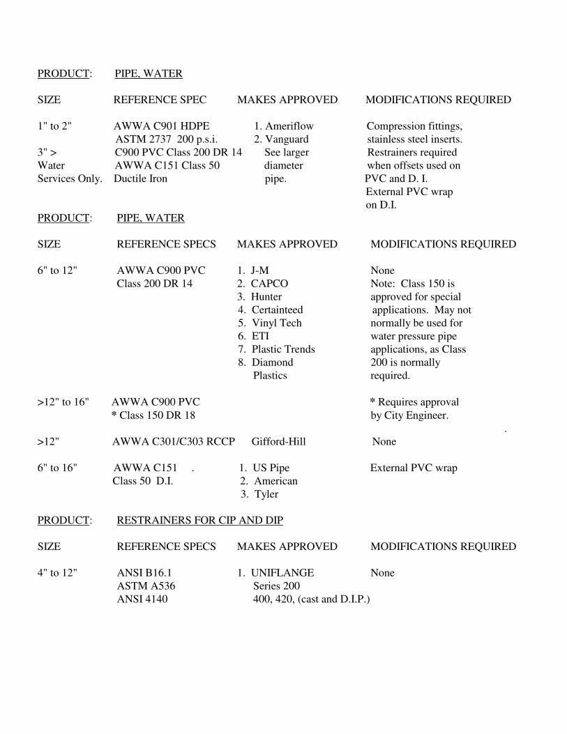
PRODUCT: PIPE, WATER SIZE REFERENCE SPEC MAKES APPROVED MODIFICATIONS REQUIRED 1" to 2" AWWA C901 HDPE 1. Ameriflow Compression fittings, ASTM 2737 200 p.s.i. 2. Vanguard stainless steel inserts. 3" > C900 PVC Class 200 DR 14 See larger Restrainers required Water AWWA C151 Class 50 diameter when offsets used on Services Only. Ductile Iron pipe. PVC and D. I. External PVC wrap on D.I. PRODUCT: PIPE, WATER SIZE REFERENCE SPECS MAKES APPROVED MODIFICATIONS REQUIRED 6" to 12" AWWA C900 PVC 1. J-M None Class 200 DR 14 2. CAPCO Note: Class 150 is 3. Hunter approved for special
4. Certainteed applications. May not 5. Vinyl Tech normally be used for 6. ETI water pressure pipe 7. Plastic Trends applications, as Class 8. Diamond 200 is normally Plastics required.
>12" to 16" AWWA C900 PVC * Requires approval
* Class 150 DR 18 by City Engineer. .
>12" AWWA C301/C303 RCCP Gifford-Hill None 6" to 16" AWWA C151 . 1. US Pipe External PVC wrap Class 50 D.I. 2. American 3. Tyler PRODUCT: RESTRAINERS FOR CIP AND DIP SIZE REFERENCE SPECS MAKES APPROVED MODIFICATIONS REQUIRED 4" to 12" ANSI B16.1 1. UNIFLANGE None ASTM A536 Series 200 ANSI 4140 400, 420, (cast and D.I.P.)
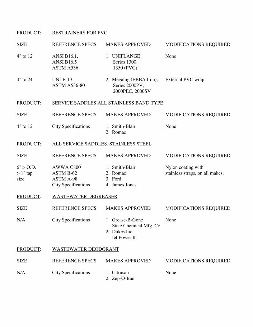
PRODUCT: RESTRAINERS FOR PVC SIZE REFERENCE SPECS MAKES APPROVED MODIFICATIONS REQUIRED 4" to 12" ANSI B16.1, 1. UNIFLANGE None ANSI B16.5 Series 1300, ASTM A536 1350 (PVC) 4" to 24" UNI-B-13, 2. Megalug (EBBA Iron), External PVC wrap ASTM A536-80 Series 2000PV, 2000PEC, 2000SV PRODUCT: SERVICE SADDLES ALL STAINLESS BAND TYPE SIZE REFERENCE SPECS MAKES APPROVED MODIFICATIONS REQUIRED 4" to 12" City Specifications 1. Smith-Blair None 2. Romac PRODUCT: ALL SERVICE SADDLES, STAINLESS STEEL SIZE REFERENCE SPECS MAKES APPROVED MODIFICATIONS REQUIRED 6" > O.D. AWWA C800 1. Smith-Blair Nylon coating with > 1" tap ASTM B-62 2. Romac stainless straps, on all makes. size ASTM A-98 3. Ford City Specifications 4. James Jones PRODUCT: WASTEWATER DEGREASER SIZE REFERENCE SPECS MAKES APPROVED MODIFICATIONS REQUIRED N/A City Specifications 1. Grease-B-Gone None
State Chemical Mfg. Co. 2. Dukes Inc. Jet Power II
PRODUCT: WASTEWATER DEODORANT SIZE REFERENCE SPECS MAKES APPROVED MODIFICATIONS REQUIRED N/A City Specifications 1. Citrusan None 2. Zep-O-Ban
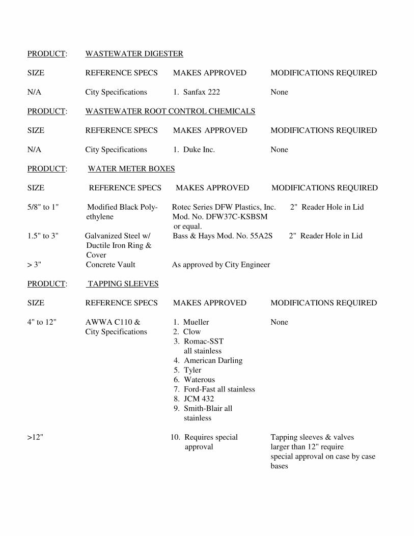
PRODUCT: WASTEWATER DIGESTER SIZE REFERENCE SPECS MAKES APPROVED MODIFICATIONS REQUIRED N/A City Specifications 1. Sanfax 222 None PRODUCT: WASTEWATER ROOT CONTROL CHEMICALS SIZE REFERENCE SPECS MAKES APPROVED MODIFICATIONS REQUIRED N/A City Specifications 1. Duke Inc. None PRODUCT: WATER METER BOXES SIZE REFERENCE SPECS MAKES APPROVED MODIFICATIONS REQUIRED 5/8" to 1" Modified Black Poly- Rotec Series DFW Plastics, Inc. 2" Reader Hole in Lid ethylene Mod. No. DFW37C-KSBSM or equal. 1.5" to 3" Galvanized Steel w/ Bass & Hays Mod. No. 55A2S 2" Reader Hole in Lid Ductile Iron Ring & Cover > 3" Concrete Vault As approved by City Engineer PRODUCT: TAPPING SLEEVES SIZE REFERENCE SPECS MAKES APPROVED MODIFICATIONS REQUIRED 4" to 12" AWWA C110 & 1. Mueller None City Specifications 2. Clow
3. Romac-SST all stainless 4. American Darling 5. Tyler 6. Waterous 7. Ford-Fast all stainless 8. JCM 432 9. Smith-Blair all stainless
>12" 10. Requires special Tapping sleeves & valves
approval larger than 12" require special approval on case by case bases

PRODUCT: VALVE, GATE RESILIENT SEAT SIZE REFERENCE SPECS MAKES APPROVED MODIFICATIONS REQUIRED 4" to 12" AWWA C509, C550 1. Mueller A-2370 None & City Specifications 2. American
Darling 80-CRS 3. Clow 6100 4. Waterous Series 500 5. Kenedy Ken-seal 6. U.S. Pipe 7. M & H 8. Wedge 6-700, 701, 702, (8) OZ All models shown -
703, 704-OZ stem changed to high 9. AVK strength. (9) Per project specifications
4" to 12" AWWA C509 10. AVK Resilient Seat Gate Valve 24" AWWA C509, C550 11. Industrial 24" None & City Specifications M & H PRODUCT: VALVES, AIR RELEASE SIZE REFERENCE SPECS MAKES APPROVED MODIFICATIONS REQUIRED 1" to 16" AWWA C509, C550 & 1. APCO Per Project Specifications City Specifications 2. Crispin PRODUCT: VALVES, BUTTERFLY 12" to 48" AWWA C504, C550 1. Mueller Internal epoxy coating & City Specifications 2. Clow (extra cost on all makes.) 3. American Darling 4. Kennedy

PRODUCT: VALVES, CHECK & DETECTOR CHECK SIZE REFERENCE SPECS MAKES APPROVED MODIFICATIONS REQUIRED 4" to 12" AWWA & City 1. Mueller None Specifications 2. American Darling 3. Kennedy 4. Hersey 5. Ames (5a) Steel check valves must be epoxy coated.
Appendix A


Appendix B
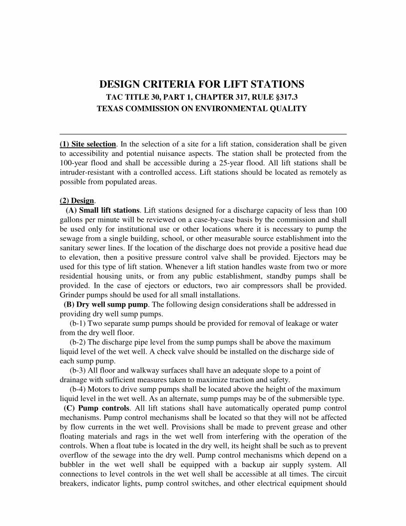
DESIGN CRITERIA FOR LIFT STATIONS
TAC TITLE 30, PART 1, CHAPTER 317, RULE §317.3 TEXAS COMMISSION ON ENVIRONMENTAL QUALITY
(1) Site selection. In the selection of a site for a lift station, consideration shall be given to accessibility and potential nuisance aspects. The station shall be protected from the 100-year flood and shall be accessible during a 25-year flood. All lift stations shall be intruder-resistant with a controlled access. Lift stations should be located as remotely as possible from populated areas. (2) Design. (A) Small lift stations. Lift stations designed for a discharge capacity of less than 100 gallons per minute will be reviewed on a case-by-case basis by the commission and shall be used only for institutional use or other locations where it is necessary to pump the sewage from a single building, school, or other measurable source establishment into the sanitary sewer lines. If the location of the discharge does not provide a positive head due to elevation, then a positive pressure control valve shall be provided. Ejectors may be used for this type of lift station. Whenever a lift station handles waste from two or more residential housing units, or from any public establishment, standby pumps shall be provided. In the case of ejectors or eductors, two air compressors shall be provided. Grinder pumps should be used for all small installations. (B) Dry well sump pump. The following design considerations shall be addressed in providing dry well sump pumps. (b-1) Two separate sump pumps should be provided for removal of leakage or water from the dry well floor. (b-2) The discharge pipe level from the sump pumps shall be above the maximum liquid level of the wet well. A check valve should be installed on the discharge side of each sump pump. (b-3) All floor and walkway surfaces shall have an adequate slope to a point of drainage with sufficient measures taken to maximize traction and safety. (b-4) Motors to drive sump pumps shall be located above the height of the maximum liquid level in the wet well. As an alternate, sump pumps may be of the submersible type. (C) Pump controls. All lift stations shall have automatically operated pump control mechanisms. Pump control mechanisms shall be located so that they will not be affected by flow currents in the wet well. Provisions shall be made to prevent grease and other floating materials and rags in the wet well from interfering with the operation of the controls. When a float tube is located in the dry well, its height shall be such as to prevent overflow of the sewage into the dry well. Pump control mechanisms which depend on a bubbler in the wet well shall be equipped with a backup air supply system. All connections to level controls in the wet well shall be accessible at all times. The circuit breakers, indicator lights, pump control switches, and other electrical equipment should

be located on a control panel at least three feet above ground surface elevation. If controls are located in a dry well, the dry well shall be protected from flooding. (D) Wet wells. (d-1) Wet wells and dry wells, including their superstructure, shall be separated by at least a watertight and gastight wall with separate lockable entrances provided to each. Equipment requiring regular or routine inspection and maintenance shall not be located in the wet well, unless the maintenance can be accomplished without entering the wet well. (d-2) Based on design flow, wet well capacity should provide a pump cycle time of not less than six minutes for those lift stations using submersible pumps and not less than 10 minutes for other nonsubmersible pump lift stations. (d-3) All influent gravity lines into a wet well shall be located where the invert is above the "off" setting liquid level of the pumps, and preferably should be located above the lead pump "on" setting. (E) Stairways. Stairways with non-slip steps shall be provided in all underground dry wells. Removable ladders may be provided in small stations where it is impractical to install stairways. (F) Ventilation. Ventilation shall be provided for lift stations, including both wet and dry wells. (f-1) Passive ventilation such as gooseneck type or turbine ventilators designed to prevent possible entry of insects or birds shall be provided in all wet wells if mechanical ventilation is not provided. All mechanical and electrical equipment in wet wells should be explosion-proof and spark-proof construction if mechanical ventilation is not provided. (f-2) Mechanical ventilation shall be provided for all dry wells below the ground surface. The ventilation equipment shall have a minimum capacity of six air changes per hour under continuous operations. At least a capacity of 30 air changes per hour shall be required where the operation is intermittent. All intermittently operated venting equipment shall be interconnected with the stations lighting system. (G) Wet well slopes. The bottom of wet wells shall have a minimum slope of 10% to the pump intakes and shall have a smooth finish. There shall be no projections in the wet well which will allow deposition of solids under ordinary operating conditions. Antivortex baffling should be considered for the pump suctions in all large sewage pumping stations (greater than five mgd firm pumping capacity). (H) Hoisting equipment. Hoisting equipment or access by hoisting equipment for the removal of pumps, motors, valves, etc., shall be incorporated in the station design. (I) Dry wells and valve vault drains. Drains from dry wells or valve vaults to the wet well shall be equipped with suitable devices to prevent entry of potentially hazardous gases. (3) Pumps. (A) General. All raw sewage pumps shall be of a non-clog design, capable of passing 2 1/2 inch diameter spheres, and shall have no less than three-inch diameter suction and discharge openings. Inspection and cleanout plates, located both on the suction and discharge sides of each pumping unit, are suggested for all nonsubmersible pumps so as to facilitate locating and removing blockage-causing materials. Where such openings are not provided on the pumps, a hand hole in the first fitting connected to the suction of each pump shall be provided. All pumps shall be securely supported so as to prevent

movement during operation. For submersible pumps, rail-type pump support systems incorporating manufacturer-approved mechanisms designed to allow the operator to remove and replace any single pump without first entering or dewatering the wet well should be provided. (B) Lift station pumping capacity. The firm pumping capacity of all lift stations shall be such that the expected peak flow can be pumped to its desired destination. Firm pumping capacity is defined as total station maximum pumping capacity with the largest pumping unit out of service. (C) Variable capacity pumps. Lift stations or transfer pumping facilities at a wastewater treatment plant or those discharging directly to the treatment plant where the plant's permitted daily average flow is equal to or greater than 100,000 gallons per day shall be provided with three or more pumps or with duplex automatically controlled variable capacity pumps or other automatic flow control devices. The pumps or other devices shall be adjusted for actual flow conditions and controlled to operate so as to minimize surges in the treatment units. No single pumping unit shall have a capacity greater than the design peak flow of the wastewater treatment plant unless flow splitting/equalization is provided. (D) Pump head calculations. The engineering design report accompanying the plans shall include system curves, pump curves, and head calculations. Calculations and pump curves at both minimum (all pumps off) and maximum (last normal operating pump on) static heads and for a C value of both 100 and 140 must be provided for each pump and for the combination of pumps (modified pump curves). Where a suction lift is required, the report shall include a calculation of the available net positive suction head (NPSH) and a comparison of that value to the required NPSH for the pump as furnished by the pump manufacturer. (E) Self-priming pumps. Only self-priming pumps or pumps with acceptable priming systems, as demonstrated by a reliable record of satisfactory operation, shall be used where the suction head is negative. All self-priming pumps shall include a means for venting the air back to the wet well when the pump is priming. (F) Pump positioning. All raw sewage pumps, other than submersible pumps without "suction" piping and self-priming units capable of satisfactory operation under any negative suction heads anticipated for the lift station under consideration, shall be positioned such that the pumps always experience, during their normal on-off cycling, a positive static suction head. (G) Grinder pumps. See §317.2(d) of this title (relating to Sewage Collection System). (4) Piping. (A) Pump suctions. Each pump shall have a separate suction pipe. Cavitation may be avoided by using eccentric reducers in lieu of typical reducers in order to prevent air pockets from forming in the suction line. (B) Valves. Full closing valves shall be installed on the discharge piping of each pump and on the suction of all dry pit pumps. A check valve shall be installed on the discharge side of each pump, preceding the full closing valve. Check valves should be of a swing check type with external levers. Rubberball check valves may be used for grinder pump installations in lieu of the swing check type. Butterfly valves, tilting disc check valves, or other valves with a pivoted disc in the flow line are not allowed. The design shall consider surge effects and provide protection where necessary. Surge relief shall be

contained in the system. (C) Valve position indicators. Gate valves should be rising-stem valves. If other than rising-stem gate valves and check valves with external levers are used, the valves shall include a position indicator to show their open and closed positions. (D) Lift station piping. Flanged pipe and fitting or welded pipe shall be used for exposed piping inside of lift stations. A flexible or flanged connection shall be installed in the piping to each pump so that the pump may be removed easily for repairs. Provisions shall be made in the design to permit flexure where pipes pass through walls of the station. Piping should normally be sized so that the maximum suction velocity does not exceed five feet per second and the maximum discharge velocity does not exceed eight feet per second. (E) Force main pipe selection. Force mains shall be a minimum of four inches in diameter, unless justified, as with the use of grinder pumps. In no case shall the velocity be less than two feet per second with only the smallest pump operating, unless special facilities are provided for cleaning the line at specified intervals or it can be shown that a flushing velocity of five feet per second or greater will occur one or more times per day. Pipe specified for force mains shall be of a type having an expected life at least as long as that of the lift station and shall be suitable for the material being pumped and the operating pressures to which it will be subjected. All pipe shall be identified in the technical specifications with appropriate ASTM, ANSI, or AWWA specifications numbers for both quality control (dimensions, tolerances, etc.) and installation (bedding, backfill, etc.). All pipe and fittings shall have a minimum working pressure rating of 150 pounds per square inch. (F) Force main tests. Final plans and specifications shall describe and require pressure testing for all installed force mains. Minimum test pressure shall be 1.5 times the maximum design pressure. (G) Air release valves. Air release valves or combination air release/vacuum valves suitable for sewage service shall be provided at all peaks in elevation. The final engineering drawings must depict all proposed force mains in both plan and profile. (5) Emergency Provisions. Lift stations shall be designed such that there is not a substantial hazard of stream pollution from overflow or surcharge onto public or private property with sewage from the lift station. Options for a reliable power source may include the following. (A) Power supply. The commission will determine the reliability of the existing commercial power service. Such determinations shall be based on power outage records obtained from the appropriate power company and presented to the commission. When requesting outage records for submittal to the commission, it is important to note that the records be in writing, bear the signature of an authorized utility employee, identify the location of the wastewater facilities being served, list the total number of outages that have occurred during the past 24 months, and indicate the duration of each recorded outage. The facility will be deemed reliable if the demonstrated wastewater retention capacity, in the station's wet well, spill retention facility, and incoming gravity sewer lines, is sufficient to insure that no discharge of untreated wastewater will occur for a length of time equal to the longest electrical outage recorded in the past 24 months. If records for the service area cannot be obtained, a 120 minute worst case outage duration will be assumed. Provisions for a minimum wastewater retention period of 20 minutes

should be considered even in those cases where power company records indicate no actual outages of more than 20 minutes occurred during the past 24 months. (B) Alternative power supply. If the existing power supply is found to be unreliable, an emergency power supply or detention facility shall be provided. Options include: (b-1) electrical service from two separate commercial power companies, provided automatic switchover capabilities are in effect; (b-2) electrical service from two independent feeder lines or substations of the same electric utility, provided automatic switchover capabilities are in effect; (b-3) on-site automatic starting electrical generators; (D) Reliance on portable generators or pumps. Proposals for the utilization of portable units shall be accompanied by a detailed report showing conclusively the ability of such a system to function satisfactorily. Portable units will be approved only in those cases where the station is equipped with an auto-dialer, telemetry device, or other acceptable operator notification device, operators knowledgeable in acquisition and startup of the portable units are on 24-hour call, the station is accessible in all weather conditions, reasonable assurances exist as to the timely availability and accessibility of the proper portable equipment, and the station is equipped with properly designed and tested quick connection facilities. This option is usually acceptable only for smaller lift stations. (6) Restoration of lift station. Provisions should be made to restore the lift station to service within four hours of outage. (7) Spill containment structures. A spill containment structure should be considered together with in-system retention in determining a total wastewater retention time. Because separate spill retention facilities are not suitable for all locations, engineers should check with the commission prior to designing such structures. The design shall provide: (A) a minimum storage volume of average design flow from the contributing area and the longest power outage during the most recent consecutive 24-month period or, if power records are not available, an assumed 24-hour outage; (B) an impermeable liner (such as concrete or synthetic fabric (20 mil thickness)) and should have an energy dissipator at the point of overflow from the lift station to prevent scour; (C) a fence with a controlled access; and (D) a plan for routine cleaning and inspection. (8) Alarm system. An audiovisual alarm system (red flashing light and horn) shall be provided for all lift stations. These alarm systems should be telemetered to a facility where 24-hour attendance is available. The alarm system shall be activated in case of power outage, pump failure, or a specified high water level.
