wastewater influent concentration ranges for pathogenic ... · typical wastewater influent...
TRANSCRIPT

1
Ultraviolet Disinfection
SALCOR 3G UNITJames E Cruver PhDJames E. Cruver PhD
SALCOR INCFallbrook, California
Typical wastewater influent concentration ranges for pathogenic and indicator organisms (Casson et al., 1990; Rose, 1988; and U.S. EPA, 1979b)
Organism Minimum, no./100 mL
Maximum, no./100 mL
Total coliforms 1 000 000 -----
Fecal coliforms 340 000 49 000 000
Fecal streptococci 64 000 4 500 000
Virus 0.5 10 000Cryptosporidium oocysts
85 1 370
Giardia cysts 80 320
Secondary effluent ranges for pathogenic and indicator organisms before disinfection (U.S. EPA, 1986)
Organism Minimum, No./100 mL
Maximum, No./100 mL
Total coliforms 45 000 2 020 000
Fecal coliforms 11 000 1 580 000
Fecal streptococcia 2 000 146 000
Viruses 0.05 1 000
Salmonella sp. 12 570
a Assuming removal efficiencies for fecal streptococci similar to the fecal coliform removal efficiencies.
Survival times of pathogens in soil and on plant surfaces (U.S. EPA, 1992)
Soil Plants
PathogenAbsolute maximumª
Common maximum
Absolute maximum
Common maximum
Bacteria 1 year 2 months 6 months 1 month
Viruses 1 year 3 months 2 months 1 month
Protozoan cysts b 10 days 2 days 5 days 2 days
Helminth ova 7 years 2 years 5 months 1 month
a Greater survival time is possible under unusual conditions such as consistently low temperatures or highly sheltered conditions (for example, heminth ova below the soil in fallow fields).b Few, if any, data are available on the survival times of Giardia cysts and Cryptosporidium oocysts.
UV Disinfection – Basic Facts
• 240‐260 nm UV light destroys microorganisms
• Dosage is product of UV intensity and exposure time
• UV light transmission and suspended matter important variables
• Low‐pressure mercury UV lamps are readily available at low cost
• Reliable delivery of UV dose to the fluid is the engineering design challenge
• Radiant power output spectra from (a) low‐pressure and • (b) medium‐pressure mercury arc lamps (Meulemans, 1987)

2
53
85
10093
66
60
80
100
120
PERCENT
Relative Percentile 253.7 nm Output vs. Ultraviolet Lamp Surface Temperature
22
40
0
20
40
12 (56.6)
20 68.0
24 (75.2)
32 (89.6)
40 (104)
48 (118.4)
60 (140)
OUTPUT
LAMP TEMPERATURE
Deg. C(Deg. F)
Relative Germicidal Effectiveness Versus UV Wavelength, in Percent
100
80
60
P tPercent40
20
00 200 220 240 260 280 300
UV WAVELENGTH, NM
UV Light: 253.7 nm
Ultraviolet absorption spectra for purine and
pyrimidine bases at pH = 7 (Davidson, 1969)
Dose and Survival
Survival Ratio or S.R. = Nt/N0 =
Where:N0 = the number of organisms initially presentN = the number of surviving organisms at timeNt = the number of surviving organisms at time tt = the exposure timeI = the ultraviolet light intensityK = a constant, which depends on the microorganism type and the ultraviolet light wavelength
Survival Versus UV Dosage
Micrococus Luteus, ATCC 9341Survival
F
UV Dose, uWatt-SecCm2 x 10-3
Fraction
UV Destruction Dosages (>99.9% Inhibition)For Important Microorganisms (mj/cm²)
•BACTERIAClostridium tetani (Tetanus) 22
Dysentery bacilli 4.2
Escherichia coli (indicator organism) 6.6
Legionella pneumophila (Legionnaires’ disease) 2.76
Mycobacterium tuberculosis 10
Pseudomones aeruginosa (slime former) 10.5
Salmonella typhosa (Typhoid fever) 4.1
Salmonella enteritides (Enteric fever) 7.6
Staphylococcus aureus 6.6
Streptococcus lactis 8.8

3
• VIRUS
UV Destruction Dosages (>90% Inhibition)For Important Microorganisms (mj/cm²)
Influenza 6.6
Polio Type I 6
Coxsachie A2 4.8
Adeno virus Type III 4.5
Ebola (Zaire) 2.3
Hepatitis C 23.3
Herpes Virus Type 4 5.3
Mumps 4.7
Norwalk 5.6
Papilloma Virus 9.8
Influenza A 2.3
Bacteriophage MS 2 23.7
Virus 90.0% 99.0% 99.9% 99.99%
Echovirus 1 8 16.5 25 33
Echovirus 2 7 14 20.5 28
Coxsackievirus B5 9.5 18 27 36
Dose requirements needed for inactivation of viruses by UV light exposure (mj/cm2)
Coxsackievirus B3 8 16 24.5 32.5
Poliovirus 1 8 15.5 23 31
Adenovirus type 32 40 78 119 160
From: Appl Environ Microbiol. 2002 October; 68(10): 5167-5169. Doi: 10. 1128/AEM.68. 10.5167-5169.2002
Bakers Yeast 8.8
Saccharomyces sp. 17.6
UV Destruction Dosages (>99.9% Inhibition)For Important Microorganisms (mj/cm²)
• YEAST AND MOLD
y p
Penicillium roqueforti 26.4
Aspergillus niger 330
Mucor racemosus A & B 35.2
Oospora lactis 11
Chlorella vulgaris (algae) 22
Fungi (typical) 45
• OTHER
UV Destruction Dosages (>99.9% Inhibition)For Important Microorganisms (mj/cm²)
Fungi (typical) 45
Cryptosporidium (Oocysts) 20 – 30
Giardia lamblia (cysts) 20 – 30
Light Transmission Through Fluids
Light Intensity Ratio or L.I.R. = Ix /I0 =
I = the initial light intensity in
Where:
W/cm2
x= the distance through which the light has traveled in the medium
= the absorption coefficient of the medium in cm-1
Ix = the light intensity at a distance x, in W/cm2
I0 = the initial light intensity, in W/cm2
Water Type
Percent Transmission of 253.7 nm UV per cm
Absorption Coefficient
(253.7 nm UV) (cm-1 )
Distilled or High Purity Water 99 0.01High Purity Drinking Water (no ferric iron or absorbing organics)
95 0.05
Typical Ultraviolet Transmission Data On Water and Wastewater
g g )Poor Quality Drinking Water (<0.3 ppm iron, slight amount of absorbing organics)
82 0.2
Filtered Secondary Effluent (<10 SS, <10 BOD)
71 0.35
Unfiltered Secondary Effluent (<30 SS, <30 BOD)
65 0.43
Lagoon Effluent (<100 SS, < 30 BOD) 61 0.5Water containing 10 ppm Humic Acid 56 0.58Water containing 10 ppm Ferric Iron 25 1.4

4
Salcor 3GNEMA 6PUV Unit
UltravioletUnitDesign
lDetails
NEMA 6P 30-Day Submergence Test Two SALCOR Model 3G Units
Operating in a Water Tank
New PC Alarm BoardAttached t thto the Junction Box Lid
5
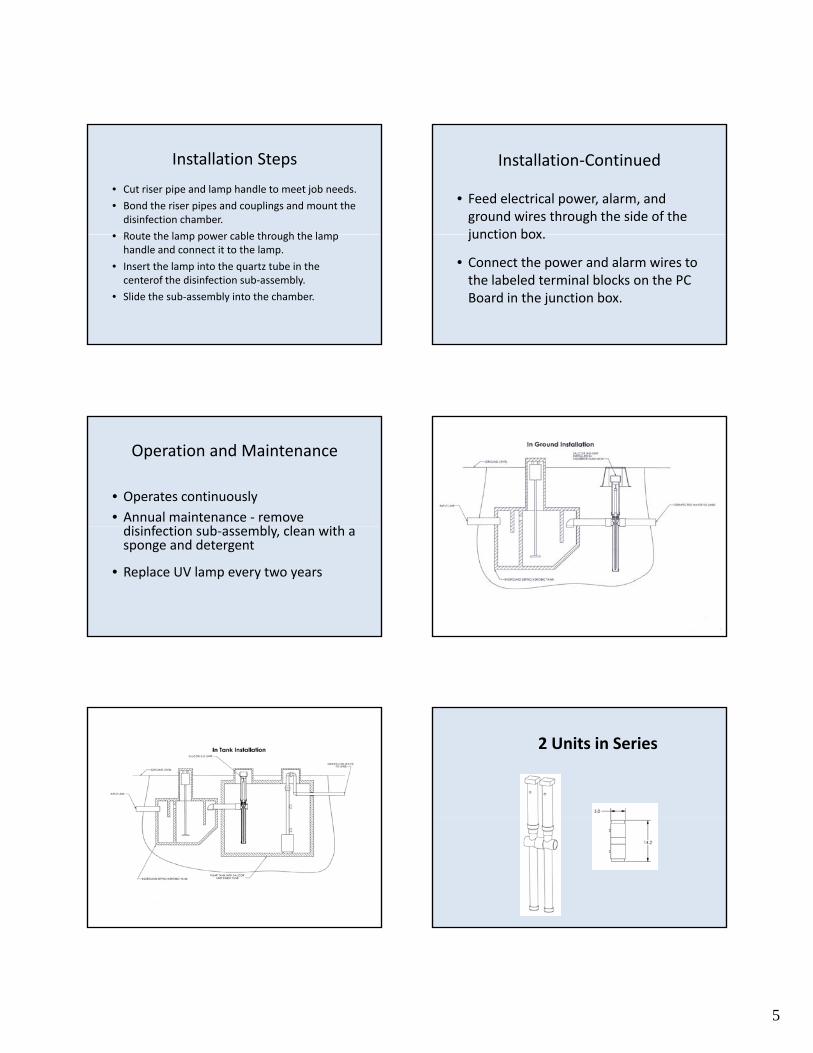
Installation Steps
• Cut riser pipe and lamp handle to meet job needs.
• Bond the riser pipes and couplings and mount the disinfection chamber.
• Route the lamp power cable through the lamp• Route the lamp power cable through the lamp handle and connect it to the lamp.
• Insert the lamp into the quartz tube in the centerof the disinfection sub‐assembly.
• Slide the sub‐assembly into the chamber.
Installation‐Continued
• Feed electrical power, alarm, and ground wires through the side of the junction boxjunction box.
• Connect the power and alarm wires to the labeled terminal blocks on the PC Board in the junction box.
Operation and Maintenance
• Operates continuously
• Annual maintenance ‐ remove di i f i b bl l i hdisinfection sub‐assembly, clean with a sponge and detergent
• Replace UV lamp every two years
2 Units in Series
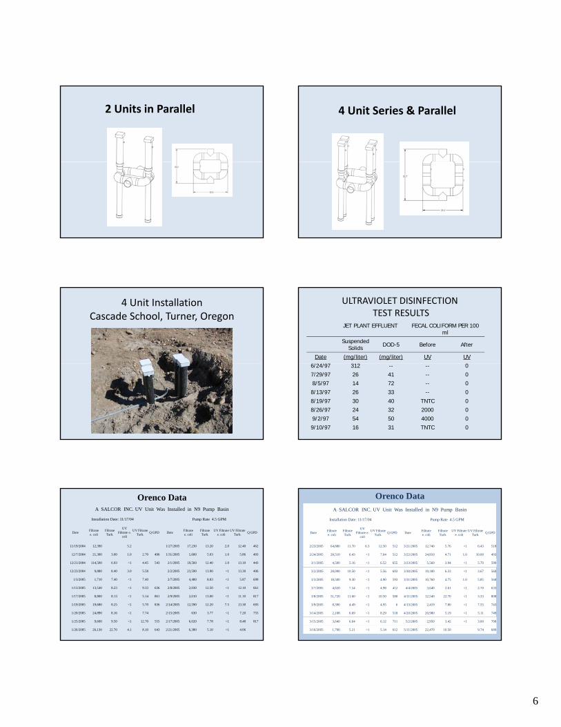
6
2 Units in Parallel 4 Unit Series & Parallel
4 Unit InstallationCascade School, Turner, Oregon
ULTRAVIOLET DISINFECTIONTEST RESULTS
JET PLANT EFFLUENT FECAL COLIFORM PER 100 ml
Suspended Solids DOD-5 Before After
Date (mg/liter) (mg/liter) UV UV
/ /6/24/97 312 -- -- 0
7/29/97 26 41 -- 0
8/5/97 14 72 -- 0
8/13/97 26 33 -- 0
8/19/97 30 40 TNTC 0
8/26/97 24 32 2000 0
9/2/97 54 50 4000 0
9/10/97 16 31 TNTC 0
Orenco DataA SALCOR INC. UV Unit Was Installed in N9 Pump Basin
Installation Date: 11/17/04 Pump Rate 4.5 GPM
DateFiltrate e. coli
Filtrate Turb.
UV Filtrate e.
coli
UV Filtrate Turb.
Q GPD DateFiltrate e. coli
Filtrate Turb.
UV Filtrate e. coli
UV Filtrate Turb.
Q GPD
11/19/2004 12,390 5.2 1/27/2005 17,230 13.20 2.0 12.40 462
12/7/2004 21,300 3.00 1.0 2.70 496 1/31/2005 1,600 5.03 1.0 5.86 493
12/21/2004 114,500 6.93 <1 4.45 543 2/1/2005 19,560 12.40 1.0 13.10 443
12/23/2004 9,880 8.40 3.0 5.58 2/2/2005 23,590 13.90 <1 13.30 406
1/3/2005 1,710 7.40 <1 7.40 2/7/2005 4,480 8.83 <1 5.87 699
1/13/2005 13,540 8.23 <1 9.33 636 2/8/2005 2,030 12.50 <1 12.10 661
1/17/2005 8,800 8.13 <1 5.14 861 2/9/2005 2,010 13.00 <1 11.10 817
1/19/2005 19,680 8.25 <1 5.70 836 2/14/2005 12,590 12.20 7.5 13.30 693
1/20/2005 24,890 8.16 <1 7.74 2/15/2005 630 3.77 <1 7.20 755
1/25/2005 9,600 9.50 <1 12.70 555 2/17/2005 6,020 7.78 <1 8.48 817
1/26/2005 26,130 22.70 4.1 8.10 643 2/21/2005 6,380 5.10 <1 4.06
Orenco DataA SALCOR INC. UV Unit Was Installed in N9 Pump Basin
Installation Date: 11/17/04 Pump Rate 4.5 GPM
DateFiltrate e. coli
Filtrate Turb.
UV Filtrate e.
coli
UV Filtrate Turb.
Q GPD DateFiltrate e. coli
Filtrate Turb.
UV Filtrate e. coli
UV Filtrate Turb.
Q GPD
2/23/2005 64,880 11.70 6.3 12.50 512 3/21/2005 12,740 5.76 <1 6.43 518
2/24/2005 28,510 6.43 <1 7.04 512 3/22/2005 24,810 4.71 1.0 10.00 493
3/1/2005 4,500 5.16 <1 6.52 655 3/23/2005 5,560 3.94 <1 5.70 599
3/2/2005 28,090 10.50 <1 5.56 693 3/30/2005 19,180 6.33 <1 3.67 560
3/3/2005 18,500 9.30 <1 4.90 593 3/31/2005 10,760 4.75 1.0 5.85 568
3/7/2005 4,650 7.54 <1 4.98 412 4/4/2005 3,640 2.61 <1 2.70 633
3/8/2005 51,720 11.60 <1 10.50 580 4/11/2005 12,540 22.70 <1 3.33 808
3/9/2005 8,390 4.49 <1 4.95 6 4/13/2005 2,419 7.80 <1 7.55 743
3/14/2005 2,108 6.69 <1 8.29 518 4/20/2005 20,980 5.19 <1 5.11 749
3/15/2005 3,640 6.64 <1 6.12 711 5/2/2005 2,950 3.42 <1 3.00 708
3/16/2005 1,790 5.21 <1 5.14 612 5/11/2005 22,470 10.50 9.74 689

7
Third Party Testing
• FAST Unit effluent
University of Rhode IslandGeorge Loomis 1999 - 2005
• Annual Service
• Lamp replacement every two years
• Geometric mean fecal coliform count 9.4/100 ml
Micro Septec Unit EffluentPoway, CA, 2002 – 2003 (10 months)
• No servicing or lamp change
• Samples taken from pump tankp p p
• Geometric mean fecal coliform count 2.6/ 100ml
Orenco SystemsSutherlin, OR, Nov 2004 ‐May 2005
• Dosing rate 4.5 GPM
• No servicing or lamp change
G t i f l lif t• Geometric mean fecal coliform count less than 2/100 ml
University of California, DavisGeorge Tchobanoglous, 2005
• Advantex AX – 20 Effluent
• Seven log MS2 Virus reduction
• Five log coliform reduction
• No micro organisms could be detected in the UV effluent
WASHINGTON STATE TESTING
• Advanced Treatment Unit & SALCOR UV• NSF Standard 40 & WA State Fecal Coliform Reduction Protocol
• Duration 26 weeks• Twenty Tests have been initiated. Eighteenare complete, and two are in progress.
• 3G UV Effluent Fecal Coliform counts ranged from 2 – 35 per 100 ml (Geometric Mean)
• Demonstrates that the 3G UV unit operates reliably without maintenance for over 6 months
Manufacturers Who Have Tested With the SALCOR 3G Unit Using the Washington State Protocol
1. Consolidated Treatment, Enviro-Guard .75 10. Jet Inc.
2. Consolidated Treatment, Multiflo 11. Enviro Flo
3. Consolidated Treatment, Nyadic 12. ANUA (Bord na Mona)
4. Delta Whitewater DF-60 13. Norweco - Singulair
5. Delta Whitewater,. Ecopod 14. AK Industries, Hydro Action
6. Orenco, AX 20N 15. Aero Tech
7. Bio Microbics, Microfast 0.5 16. Ecological Tanks, Aqua Safe,
8. Quanics, ATS-CSAT-8-AC-C500 17. Clearstream
9. Hoot Aerobics 18. Aqua Klear

8
WASHINGTON STATE TEST RESULTS SUMMARY
Treatment Type Geometric Mean Fecal Coliform/100 ml
Suspended Growth 18 – 33Suspended Growth 18 33
Fixed/Suspended Growth 26 – 56
Fixed Growth – Textile 1.7
Fixed Growth – Peat 2.1
Fixed Growth – Foam 16
CHLORINE REACTIONS
• Cl2 & H2O = HCl + HOCl
• HOCl = H+ + OCl‐
Effect of pH on Dissociation of Hypochlorous Acid at 30° C (86° F)
pH Value %HOCL %OCI
5.0 99.7 0.3
6.0 96.9 3.1
7 0 75 9 24 17.0 75.9 24.1
7.2 66.5 33.5
7.4 55.6 44.4
7.6 44.2 55.8
8.0 23.7 76.3
9.0 3.0 97.0
Figure 5.5 Escherichia coli kill times versus residual concentration (from Clarke, N.A., et al. [1964] Human Viruses in Water: Source, Survival and Removability, y,Advances in Water Pollution Research. Vol. 2, Pergamon Press, London, U.K., 523
Lethality Coefficient for Ozone and Chlorine
DisinfectantEnteric Bacteria Viruses Spores
Amoebic Cysts
Ozone 500 5.0 2 0.5
Chlorine as HOCl 20 1.0 0.05 0.05
Chlorine as OCl 0.2 <0.02 <0.0005 0.0005
Chlorine as NH2Cl 0.1 0.005 0.001 0.02

9
EFFECT UV CHLORINE (tablets) OZONE
pH No Yes YesTemperature No Yes Yes
Residual No Yes Dependent on pH & temp.
Contract time required Very short Very long Medium
Operator skill required Little Little ModerateEquipment Little Moderate High
Summary Comparison of UV, Chlorine & Ozone Disinfection for Small Wastewater Flows
q pmaintenance Little Moderate High
Ammonia interference No Yes YesWater chemistry change No Yes Yes
Dissolved iron interference Yes Yes Yes
Dissolved organic interference (e.g. phenol, humic acid, lignin sulfonates)
Yes Yes Yes
Capital cost Low Medium HighOperating cost Low High Medium
SALCOR INC.P. O. Box 1090
Fallbrook, CA 92088-1090Telephone: (760) 731-0745
Fax: (760) 731-2405
INSTALLATIONMANUAL
UV DISINFECTION UNIT MODEL 3G
April, 2011
I. INSTALLATION INSTRUCTIONSWARNING! Improper connection of the appliance grounding conductor can result in the risk of electric shock. Check with a qualified electrician or service representative if you are in doubt about whether the appliance is properly grounded.Open and carefully unpack the shipping carton. Check for any damage that may have occurred in shipping. If there are any problems, call SALCOR INC. at 760-731-0745 or fax to SALCOR INC. at 760-731-2405 and explain the problem(s).The following list describes the components that are contained in the shipping carton.
•Riser pipe: Four-inch diameter ABS pipe. The one-inch PVC bubble-wrapped insertion and removal handle containing the UV lamp is packed inside the four-inch riser pipe.•Disinfection chamber: three-inch diameter ABS pipe with 4-inch inlet and outlet hubs.•Disinfection subassembly consisting of an anodized aluminum frame supporting a Teflon sleeve containing a pure fused quartz tube. This complete item is packed inside of the three-inch disinfection chamber. •One-inch White PVC handle which is used for inserting and removing h di i f i b blthe disinfection subassembly.
•The Long Life UV lamp is packed inside of the PVC handle.•Electrical subassembly junction box (rated 6P) with pre wired alarm board, electronic ballast, and the lamp cord supplying power to the UV lamp. •Two 4-inch Schedule 40 ABS pipe couplings.•Watertight connection(s) for bringing the power and alarm wires into the junction box. Flexible conduit should be used to connect to these fittings.
There will be some additional items needed for installation, which are:•ABS cement (also multipurpose cement if bonding to PVC pipe)•Teflon tape for sealing PVC and Watertight connectors.•Isopropyl (rubbing) alcohol•Glycerin (available from drug stores)Glycerin (available from drug stores)•Power and Alarm Wires•Power and Alarm Wire Watertight Flexible Conduit for connecting to the Junction Box watertight connectors•Valve Box cover if unit is to be installed at or above ground•RTV Sealant A schematic drawing of the unit is shown in figure 1.

10
II. TWO INSTALLATION OPTIONS1. In the ground: couple the 4-inch inlet to the exit pipe of the
pretreatment unit, and couple the 4-inch outlet to the drain field pipe. See Figure 2.
2. In a Pump Tank: couple the UV unit inlet pipe to the pretreatment unit exit pipe at the entrance of the pump tank. See Figure 3.Note: Figure 1 indicates that the electrical junction box should be placed at ground level. If this should pose a problem with lawn mowers, etc., then the box could be placed below grade in an irrigation or water meter box. Another possibility is to use a hollow artificial rock to cover the junction box.The Junction box is rated NEMA 6P. To be safe, however, the junction box should be protected from flooding.For in-pump tank installations, care should be taken to prevent flooding of the junction box.

11

12
SALCOR INCP.O. Box 1090 Fallbrook, CA 92088-1090
Telephone: 760-731-0745Fax: 760-731-2405
LIMITED WARRANTYSALCOR MODEL 3G UV DISINFECTION UNIT
This warranty is given by SALCOR Inc. for the benefit of the first purchaser of the product to which the warrantyapplies, the warranty applies only to those parts which are manufactured and delivered by SALCOR Inc.The warranty is that the parts manufactured and delivered by SALCOR Inc. will be free from defects in the material orworkmanship under normal use and service according to the Installation and Operating Instructions for the timespecified below.I n the event of a failure of a part due to such a covered defect, SALCOR Inc. will repair or replace, at its option, thedefective part at its factory located at 447-D Ammunition Road, Fallbrook, CA 92028. At the option of SALCOR Inc,repairs or replacement may be made at the site of equipment installation.The part must be returned to the factory at the expense of the person claiming the benefit of the warranty unlessSALCOR Inc elects to repair or replace the defective part at the installed siteSALCOR Inc. elects to repair or replace the defective part at the installed site.The warranty shall be for a period of twenty four (24) months after the date of delivery of the product, or the specifiedservice life of the product, whichever period is the shortest. All products for which warranty claims are filed must bereturned as provided above to the factory within thirty (30) days from the date of the claimed malfunction in order forthis warranty to be effective. The only entity authorized to do any warranty repairs is SALCOR Inc.The repairs or replacement by SALCOR Inc. will be accomplished within twenty (20) days from receipt of the defectiveparts at the factory.This warranty is expressed in lieu of all other warranties, expressed or implied, including the implied warranty of fitnessfor a particular purpose, and of all other obligations or liabilities on the part of SALCOR Inc., and it neither assumes norauthorizes any other persons to assume for SALCOR Inc. any other liabilities in connection with the sale of the products.This warranty does not cover parts of products made by others, or products or any part thereof which have been repairedor altered, except by SALCOR Inc., which shall have been subjected to misuses, negligence, or accident,SALCOR Inc. shall not be liable for damage or delay suffered by the purchaser regardless of whether such damages aregeneral, special, or consequential in nature whether caused by defective material or workmanship, or otherwise, orwhether caused by SALCOR Inc. negligence, regardless of degree.
A few older UV installations and how they look todayy y
UV DISINFECTION‘We all hate it’
13
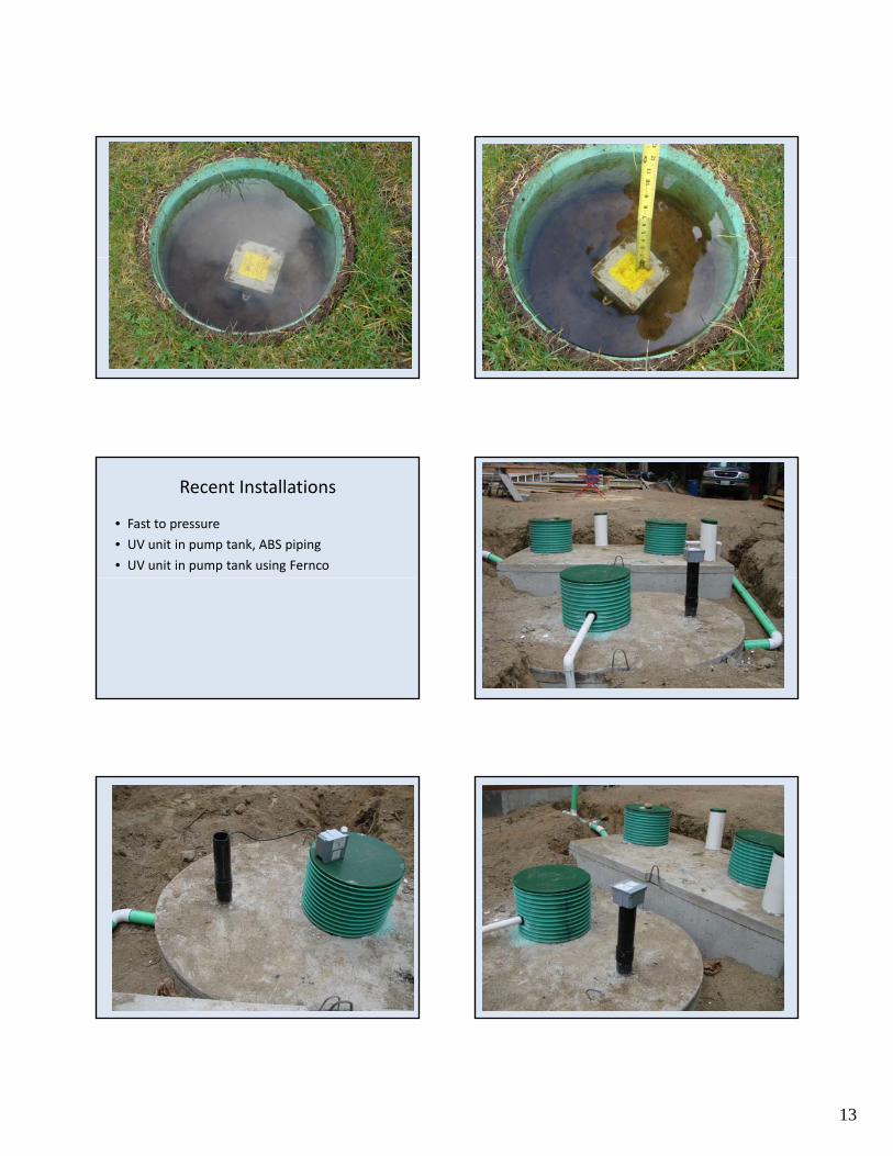
Recent Installations
• Fast to pressure
• UV unit in pump tank, ABS piping
• UV unit in pump tank using Fernco

14
Norweco to Pressure
• 1 year old
• Burned and still live, no breakers tripped and fuses still intact
O i i f hi• One circuit for everything
• Bulb melted down in crystal

15
Norweco to Pressure – new
• Installation issues
• Electrician issues
• Control panel placement
• Landscape issues
• Signed off……… and will fail

16

17
Uv ‘Disinfector’
• Power still on and smoking
Creative Wiring

18
Recent Installations
• Accesibility
• Deposits on bulb
• Cleaning the Teflon Sheath

19
More creative wiring
• Improper glue used
• Not enough slack
• Box ‘repaired’
• Accessibility
• Crystal and connection burned
• Wire connectors

20
Bad Installation Practices are Common
• Junction boxes
• Conduit
• Service providers

21
Settling Issues
• Quick to backfill….
• Often big consequences

22
Salcor install
• Settling problem
• Bends or breaks the abs piping

23
Improper backfill
• Warped, bent piping or broken connections
• Titled baffles
• Other consequences
• How to correct?
Homeowners…..
• Accessibility – they don’t believe in it
• Educate them from the start

24

25
Control Panel Placement
• Too low
• Practicality of monitoring
• Liability
Turbidity

26
Waste strength
• Needs to be clean enough for UV to work
• Filters
• Turbidity

27