waste not want not — with the help of evaporation
Post on 01-Nov-2016
213 views
TRANSCRIPT
Waste Not Want Not With The Help Of Evaporation
W hen considering techniques for c lean ing d i r ty
waste waters, thoughts are generally directed toward conventional equipment in- volving filter presses, cy- c l o n e s e p a r a t o r s , membranes and~or reverse osmosis• Tony Robinson, Sales Engineering Man- ager of Stork Engineering, recommends a look at forced recirculation eva- porator technology.
Contaminating water is get- t ing expensive• Str ingent pollution control legislat ion is increasing the l ikel ihood of punitive financial penal- ties being imposed on orga- n isa t ions that ignore or neglect their duty of care for the environment.
Bad water cannot reck- lessly be poured into a drain. Hazardous and other- wise undesirable constitu- ents must first be isolated,
or steadily rising costs in- curred for off-site disposal and treatment. Furthermore taxes are being imposed on dumping of waste.
Pollution control is uni- versal ly accepted as neces- sary, but the expense of i m p l e m e n t i n g it can be minimised by effective on- si te t reatment . The twin aims are to clean up the contaminated waste stream so that relat ively pure water can be safely discharged to sewer, and to reduce the bulk and consequently the cost of d ispos ing of the ult imate waste fraction. Bet- ter still, both treated water and separated pol lutants can possibly be recycled within the plant.
The forced recirculation evaporator, Stork Engineer- ing believe, is one answer to the industry's demand for f lexible and adaptable equipment for inexpensive and continuous t reatment of c o n t a m i n a t e d w a s t e streams.
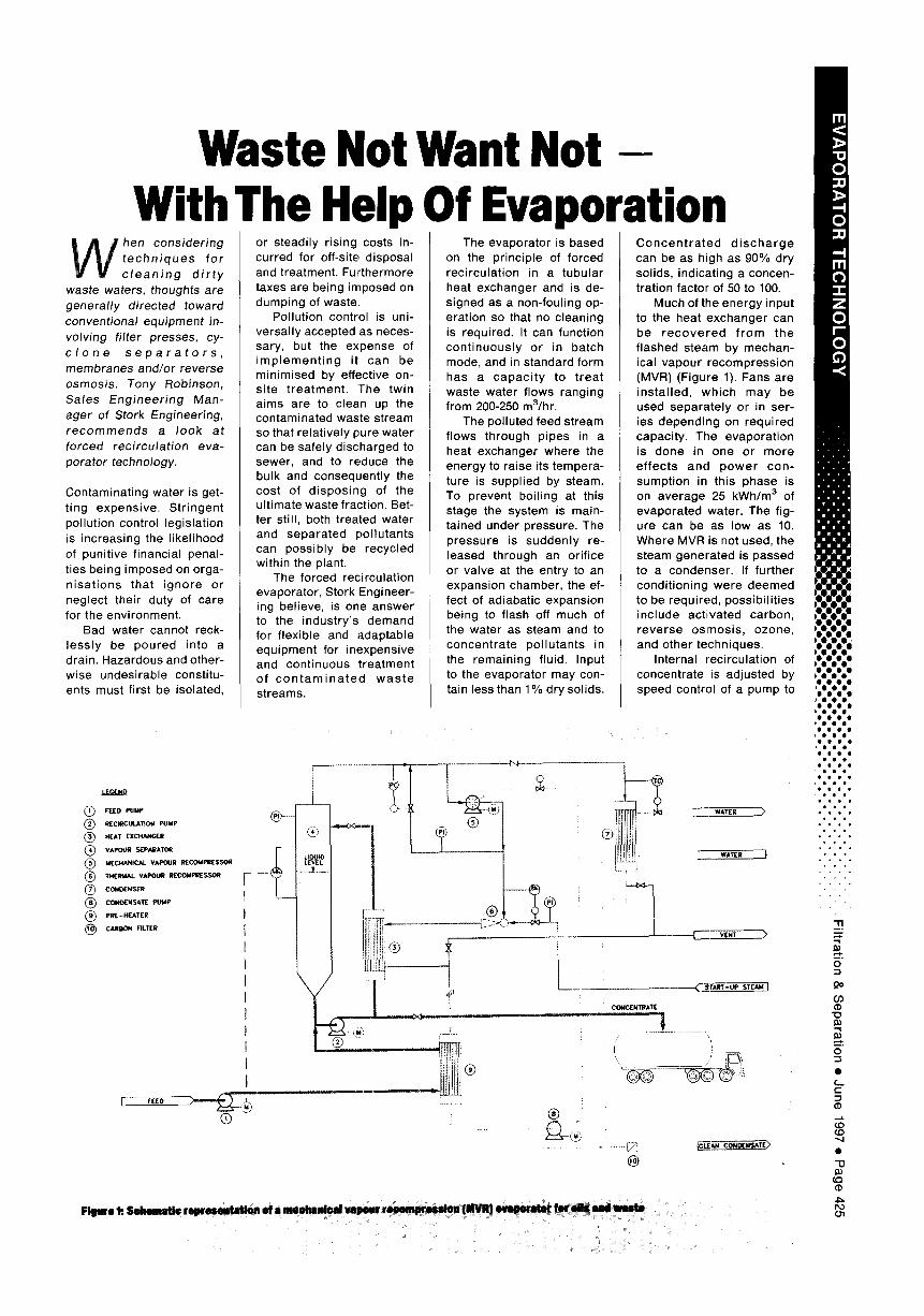
The evaporator is based on the principle of forced recirculat ion in a tubular heat exchanger and is de- signed as a non-fouling op- eration so that no cleaning is required. It can function cont inuously or in batch mode, and in standard form has a capac i t y to t reat waste water f lows ranging from 200-250 m3/hr.
The polluted feed stream flows through pipes in a heat exchanger where the energy to raise its tempera- ture is supplied by steam. To prevent boil ing at this stage the system is main- tained under pressure• The pressure is suddenly re- leased through an orif ice or valve at the entry to an expansion chamber, the ef- fect of adiabatic expansion being to flash off much of the water as steam and to concentrate pol lutants in the remaining fluid. Input to the evaporator may con- tain less than 1% drysol ids.
C o n c e n t r a t e d d i s c h a r g e can be as high as 90% dry solids, indicating a concen- tration factor of 50 to 100.
Much of the energy input to the heat exchanger can be r e c o v e r e d f rom the f lashed steam by mechan- ical vapour recompression (MVR) (Figure 1). Fans are insta l led, which may be used separate ly or in ser- ies depending on required capacity. The evaporat ion is done in one or more ef fects and p o w e r con- sumption in this phase is on average 25 kWh/m 3 of evaporated water. The fig- ure can be as low as 10. Where MVR is not used, the steam generated is passed to a condenser. If further condi t ioning were deemed to be required, possibi l i t ies include act ivated carbon, reverse osmosis , ozone, and other techniques.
Internal recirculation of concentrate is adjusted by speed control of a pump to
( ~ FEED PUMP
( ~ I~EC I~ULATION PUMP
(~ ) H[AT [XCHANGI[ll
( ~ VAPOUR $EPkI~ATO~
(~ ) MECHANICAL VAPOUR RIECOI4PI~E$SOR
( ~ TH(IP,4~L VAPOU~ RECOMPII~SSO~
( ~ CONC~NSER
~8~ CONDL-NSAT~ PUMP
( ~ PfllE- HEATE R
CARBON FILTER
r
FEE°
Q
?-.j
i . . . . j
L
WATrR >
WATrR }
VENT
®
CoNcrk'rRAT[
. . . .
Figure k SehomMio reweseatMion ol a meehanleal vapour ~ (NVR) ~ for oils amd ~
m <
"0 0
- t 0
.-4 m C~ - r Z O r - O . <
t • • :
u E a • i l l
O 0 0 0 O 0
o o o o O 0
i:!:!:! 0 0 e
O i l 0 O i l
O O e O
g O 0 e O o O
e o e e o o o
e 0 e . e e
* * o J . , , j
, , , J
, ° o , ° , ,
• • •
• • •
stabi l ise flow. Design fea- tures of the evaporator in- c lude a separator whose efficiency on entrainments is be t t e r than 99.99%• Nevertheless since the feed may contain volat i le hydro- carbons and organ ics it could be necessary to use activated carbon for con- densate treatment.
Care is needed at the h igh t e m p e r a t u r e s and pressures prevai l ing in the heat exchanger , par t icu- la r ly to avo id a r isk of f ou l i ng wh ich cou ld be caused by overheating the waste stream• Detailed de- sign ensures that tempera- ture of the hottest part of the internal tube wall is main- ta ined be low the cr i t ical point where polymerisat ion, dissociation or breakdown might begin to cause pro- blems. Steps are also taken to el iminate a risk of foam formation in the expansion chamber, using a deaera- tion technique•
TYPICAL ENGINEERING WASTES
Volvo Aero C o r p o r a t i o n plant at Trollh&ttan in Swe- den was faced with a need, common to many engineer- ing facil it ies, for cleaning up discharges of dirty water. Contaminated f luids arise f rom its manufac tu re of parts for aviat ion jet en- g ines, work in which it col laborates with GE, Rolls Royce and BMW.
The waste waters origi- nate ma in l y f rom th ree sources: oil emulsions from machine tools, r inse waters and process l iquids from water based cleaning, and liquid penetrants used for crack testing.
Volvo first installed ultra- f i l trat ion plant to concen- trate 20 000 m3/year of oi ly residues. This effort to pur- ify effluents was only par- t ial ly successful, inasmuch as COD levels in the mem- brane fi l trate remained in the region 2000 to 6000 mg/ I. BOD/COD ratio was rela- t ively low but toxicity high.
The eventual so lu t ion was to install a reverse osmosis plant to pre-con- centrate the permeate from the UF plant, fol lowed by a forced rec i rcu la t ion eva- porator as a final treatment stage. The combinat ion suc-
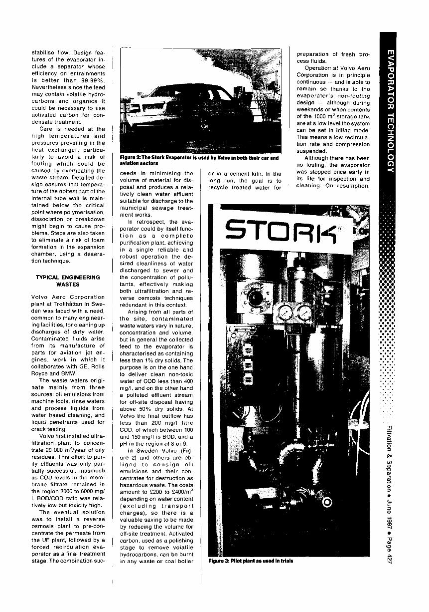
Figure 2: The Stork Evaporator is used by Volvo in both their car and aviation sectors
ceeds in m in im is ing the volume of material for dis- posal and produces a rela- t ively clean water effluent suitable for discharge to the mun ic ipa l sewage t reat - ment works•
In retrospect, the eva- porator could by itself func- t i o n as a c o m p l e t e purif ication plant, achieving in a s ing le re l iab le and robust operat ion the de- sired cleanliness of water d ischarged to sewer and the concentration of pollu- tants, e f fect ive ly mak ing both ultrafi l tration and re- verse osmosis techniques redundant in this context.
Arising from all parts of the s i te , c o n t a m i n a t e d waste waters vary in nature, concentration and volume, but in general the col lected feed to the evaporator is characterised as containing less than 1% dry solids. The purpose is on the one hand to del iver clean non-toxic water of COD less than 400 mg/I, and on the other hand a polluted effluent stream for off-site disposal having above 50% dry solids• At Volvo the final outf low has less than 200 mg/I l i t re COD, of which between 100 and 150 mg/I is BOD, and a pH in the region of 8 or 9•
In Sweden Volvo (Fig- ure 2) and others are ob- l i g e d to c o n s i g n o i l emuls ions and their con- centrates for destruction as hazardous waste. The costs amount to £200 to £400/m 3 depending on water content ( e x c l u d i n g t r a n s p o r t charges) , so there is a valuable saving to be made by reducing the volume for off-site treatment. Activated carbon, used as a polishing stage to remove volat i le hydrocarbons, can be burnt in any waste or coal boi ler
or in a cement kiln. In the long run, the goal is to recycle t reated water for
preparat ion of fresh pro- cess fluids•
Operation at Volvo Aero Corporation is in principle continuous -- and is able to remain so thanks to the e v a p o r a t o r ' s non- fou l ing design -- although during weekends or when contents of the 1000 m 3 storage tank are at a low level the system can be set in idling mode. This means a low recircula- tion rate and compression suspended•
Although there has been no fouling, the evaporator was stopped once early in its life for inspection and cleaning• On resumpt ion,
Figure 3: Pilot plant as used in trials
I"11
0
- 4 0
- t m 0 -1- z 0 r - 0
• . . ' ,
• • | | 1
• • i l l
• i
~n m j l
K ]8~|
• 0 0 ' 0 0 4 0 0 0 •
0 0 0 (J O 0
:!:i:!: • • •
• • 4
° o ° o ° o • • •
• • •
• • o • 8 J
• • • ,
• ° • • . •
• • . • ° •
• o .
" i 3
co
o
t
e'-"
" , 4
e
" U
t ~ - M
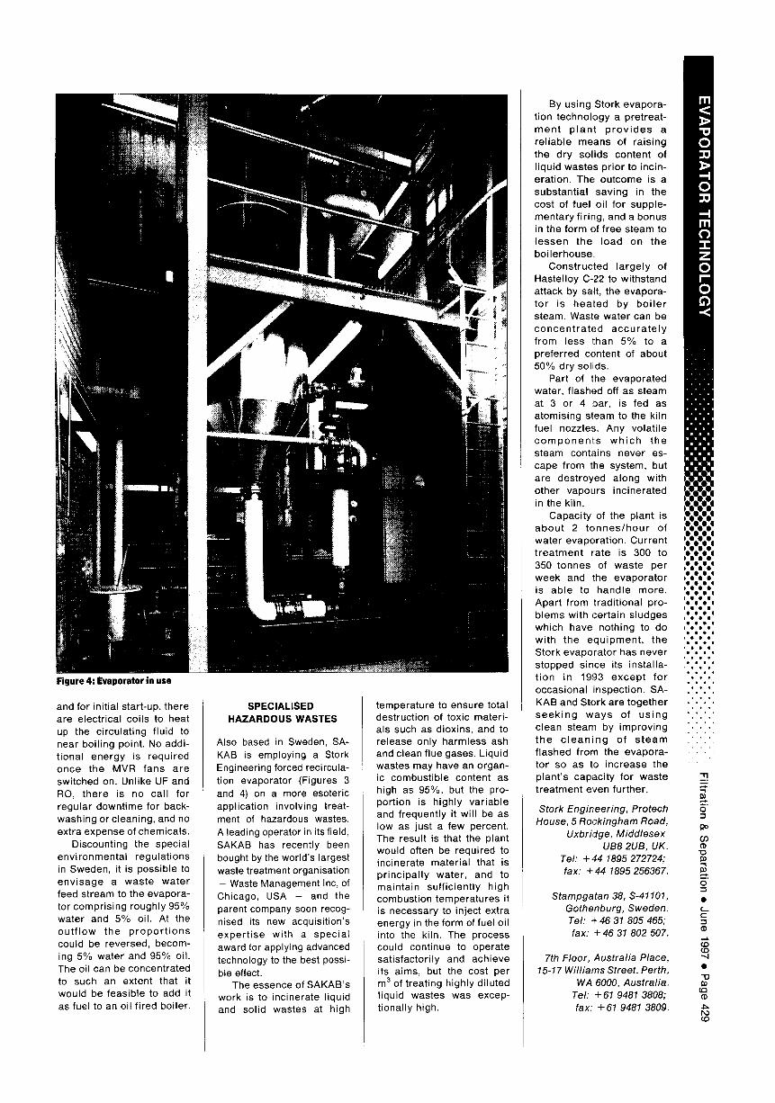
Figure 4: Evaporator in use
and for initial start-up, there are electrical coils to heat up the circulating fluid to near boi l ing point. No addi- t ional energy is required once the MVR fans are switched on. Unlike UF and RO, there is no call for regular downt ime for back- washing or cleaning, and no extra expense of chemicals.
Discounting the special envi ronmental regulat ions in Sweden, it is possible to env isage a waste water feed stream to the evapora- tor compris ing roughly 95% water and 5% oil. At the ou t f l ow the p r o p o r t i o n s could be reversed, becom- ing 5% water and 95% oil. The oil can be concentrated to such an extent that it would be feasible to add it as fuel to an oil f ired boiler•
S P E C I A L I S E D H A Z A R D O U S W A S T E S
Also based in Sweden, SA- KAB is employing a Stork Engineering forced recircula- tion evaporator (Figures 3 and 4) on a more esoteric application involving treat- ment of hazardous wastes. A leading operator in its field, SAKAB has recently been bought by the world's largest waste treatment organisation - Waste Management Inc, of Chicago, USA - and the parent company soon recog- nised its new acquisition's exper t i se with a specia l award for applying advanced technology to the best possi- ble effect.
The essence of SAKAB's work is to incinerate liquid and solid wastes at high
temperature to ensure total destruction of toxic materi- als such as dioxins, and to release only harmless ash and clean flue gases. Liquid wastes may have an organ- ic combust ible content as high as 95%, but the pro- portion is highly var iable and frequently it wi l l be as low as just a few percent. The result is that the plant would often be required to incinerate material that is pr inc ipa l ly water, and to maintain suff iciently high combustion temperatures it is necessary to inject extra energy in the form of fuel oil into the kiln. The process could continue to operate sat isfactori ly and achieve its aims, but the cost per m 3 of treating highly diluted l iquid wastes was excep- t ionally high.
By using Stork evapora- tion technology a pretreat- m e n t p lan t p r o v i d e s a re l iable means of raising the dry sol ids content of l iquid wastes pr ior to incin- eration. The outcome is a substant ial saving in the cost of fuel oil for supple- mentary firing, and a bonus in the form of free steam to lessen the load on the boi lerhouse.
Constructed largely of Hastelloy C-22 to withstand attack by salt, the evapora- tor is heated by bo i l e r steam. Waste water can be concen t ra ted accu ra te l y f rom less than 5% to a preferred content of about 50% dry solids.
Part of the evaporated water, flashed off as steam at 3 or 4 bar, is fed as atomising steam to the kiln fuel nozzles. Any volat i le c o m p o n e n t s w h i c h the steam contains never es- cape from the system, but are destroyed along with other vapours incinerated in the kiln.
Capacity of the plant is abou t 2 t o n n e s / h o u r of water evaporat ion. Current t rea tment rate is 300 to 350 tonnes of waste per week and the evaporator is able to handle more. Apart from tradit ional pro- b lems with certain sludges which have nothing to do wi th the equ ipment , the Stork evaporator has never stopped since its instal la- t ion in 1993 excep t for occasional inspection. SA- KAB and Stork are together s e e k i n g ways of us ing clean steam by improving the c l e a n i n g of s t e a m flashed from the evapora- tor so as to increase the plant's capacity for waste t reatment even further.
Stork Engineering, Protech House, 5 Rockingham Road,
Uxbridge, Middlesex UB8 2UB, UK.
Tel: + 44 1895 272724; fax: + 44 1895 256367.
Stampgatan 38, S-41101, Gothenburg, Sweden. Tel: + 46 31 805 465; fax: + 46 31 802 507.
7th Floor, Australia Place, 15-17 Williams Street, Perth,
WA 6000, Australia. Tel: + 61 9481 3808; fax: + 61 9481 3809.
m
0
1> - I 0
- t m 0
Z 0 f - -
0 C) .<
l X I
O O 0 0 0 o
Oo°o° o 0 0 0 0 0 0
O O O 0 0 0
0 0 0 0 0 0
c o o o e o
o e o e ° l ° 4 °
e e e e o e e e e
e o e e
o ° e • e
o o . . I . I
. ° ° ° ' ' ° °
• t ° • ° . .
0
m
0
e