washoe county addendum to special use permit application · pdf filewashoe county addendum to...
TRANSCRIPT
_________________________________________________________________________
WASHOE COUNTY
ADDENDUM to Special Use Permit Application
for
Ruby Pipeline Project
_________________________________________________________________________
Submitted by
January 11, 2010
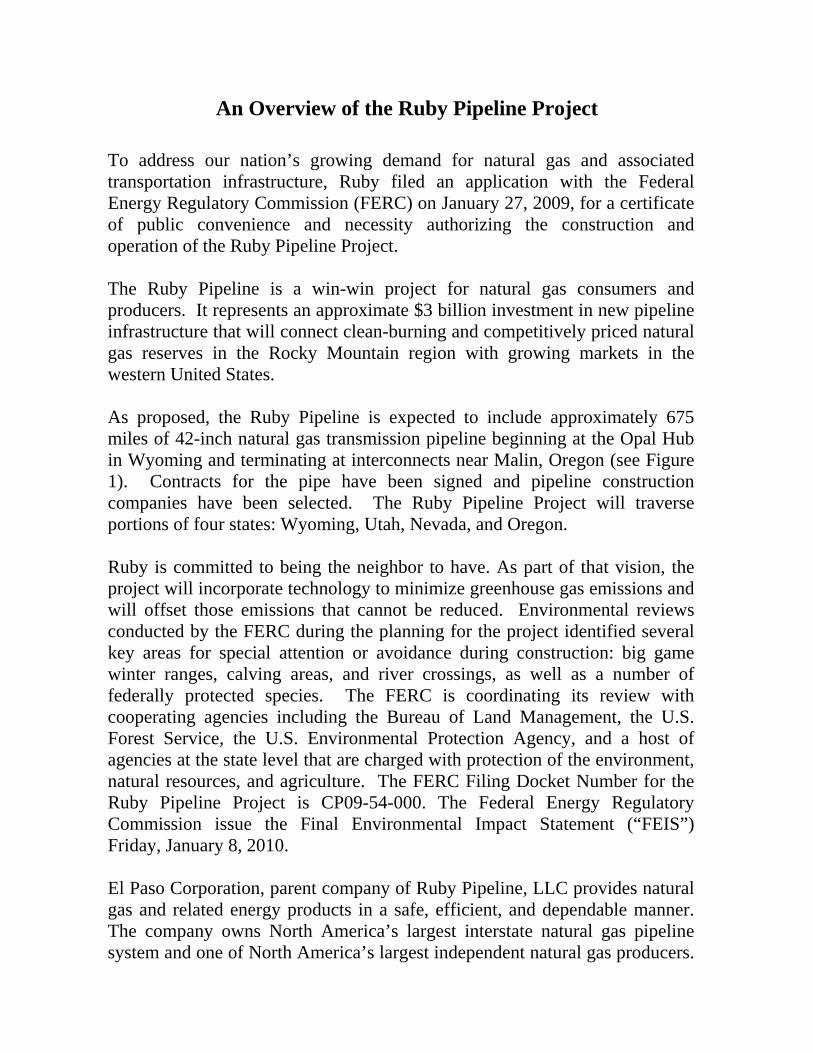
An Overview of the Ruby Pipeline Project
To address our nation’s growing demand for natural gas and associated transportation infrastructure, Ruby filed an application with the Federal Energy Regulatory Commission (FERC) on January 27, 2009, for a certificate of public convenience and necessity authorizing the construction and operation of the Ruby Pipeline Project. The Ruby Pipeline is a win-win project for natural gas consumers and producers. It represents an approximate $3 billion investment in new pipeline infrastructure that will connect clean-burning and competitively priced natural gas reserves in the Rocky Mountain region with growing markets in the western United States. As proposed, the Ruby Pipeline is expected to include approximately 675 miles of 42-inch natural gas transmission pipeline beginning at the Opal Hub in Wyoming and terminating at interconnects near Malin, Oregon (see Figure 1). Contracts for the pipe have been signed and pipeline construction companies have been selected. The Ruby Pipeline Project will traverse portions of four states: Wyoming, Utah, Nevada, and Oregon. Ruby is committed to being the neighbor to have. As part of that vision, the project will incorporate technology to minimize greenhouse gas emissions and will offset those emissions that cannot be reduced. Environmental reviews conducted by the FERC during the planning for the project identified several key areas for special attention or avoidance during construction: big game winter ranges, calving areas, and river crossings, as well as a number of federally protected species. The FERC is coordinating its review with cooperating agencies including the Bureau of Land Management, the U.S. Forest Service, the U.S. Environmental Protection Agency, and a host of agencies at the state level that are charged with protection of the environment, natural resources, and agriculture. The FERC Filing Docket Number for the Ruby Pipeline Project is CP09-54-000. The Federal Energy Regulatory Commission issue the Final Environmental Impact Statement (“FEIS”) Friday, January 8, 2010. El Paso Corporation, parent company of Ruby Pipeline, LLC provides natural gas and related energy products in a safe, efficient, and dependable manner. The company owns North America’s largest interstate natural gas pipeline system and one of North America’s largest independent natural gas producers.

RUBY PIPELINE PROJECT WASHOE COUNTY, NEVADA INFORMATION FACT SHEET
Length in Miles across Washoe County: 275,918.91 Total Feet or 52.257 Miles
Private Lands: 28,138.40’ or 5.329 Miles 9.14% BLM Lands: 247,780.51’ or 46.928 Miles 90.86%
Total Acres Impacted during construction (Temporary Right-Of-Way) Private Lands 2,984,773.30 Square Feet or 68.521 Acres
BLM Lands 21,196,974.31 Feet or 486.616 Acres
Permanent Right-Of-Way Acres: Private Lands 1,406,920.00 Square Feet or 32.298 Acres BLM Lands 12,389,025.50 Square Feet or 284.413 Acres
Location & Size of Pipe Storage Yard Located adjacent to Right-of-Way:
Pipe will be hauled from the Gerlach Pipeline Inventory Facility located at the Union Pacific Rail Road spur track, Gerlach, NV and temporarily stored at a pipe yard location until it can be strung along the construction right of way. This pipe storage yard will be approximately 30 acres and located on BLM property in parts of Township 43 North, Range 21 East, Section 34 and Township 42 North, Range 21 East, Section 3.
Estimated Miles of County Roads Used:
212.40 Miles

United States Department of the Interior
BUREAU OF LAND MANAGEMENT Washington, D. C. 20240
125 South 600 West Price, UT 84501
http://www.blm.gov January 7, 2010
IN REPLY REFER TO: 288O NVN-084650, OR-64807, UTU-82880, WYW-171168 (WO-350) Mr. Adrian P. Freund, FAICP Community Development Director Community Development Department Washoe County P. O. Box 1130 Reno, NV 89520-0027 Dear Mr. Freund: This letter is written per the request of Ruby Pipeline, LLC to inform Washoe County, Nevada that the Bureau of Land Management (BLM) is aware of the Ruby Pipeline project and related facilities proposed to be constructed in Washoe County. This statement is being provided to aid Ruby Pipeline, LLC in pursuing necessary permits and authorizations with Washoe County for the proposed pipeline project. Please be advised that this proposed project is currently being evaluated by the Federal Energy (FERC) and BLM and no final decision has been made whether to grant a right-of-way across Federal land for the pipeline or to authorize construction of the pipeline and related facilities. No decisions have been made as to the final pipeline route or the location of any related facilities for the pipeline. At your discretion, BLM requests that you share this information with the appropriate County agencies involved in working with Ruby Pipeline representatives to obtain necessary permits and authorizations for their pipeline project. If you have any questions, please feel free to call me at (435) 636-3616. Sincerely, Mark A. Mackiewicz, PMP National Project Manager

3
3
3
3
!
!!!
!
!
!
!
!
!
Ruby Pipeline ProjectWashoe County
Dec 10, 20091:200,223
1 inch = 16,685 feet
WASH
OE C
OUNT
Y
WASH
OE C
OUNT
YHU
MBOL
DT C
OUNT
Y
WASHOE COUNTY
LAKE COUNTYWASHOE COUNTY


_______________________________________________________________________________
WASHOE COUNTY
Application for Director’s Modification
for
Ruby Pipeline Project _______________________________________________________________________________
Submitted by
January 11, 2010
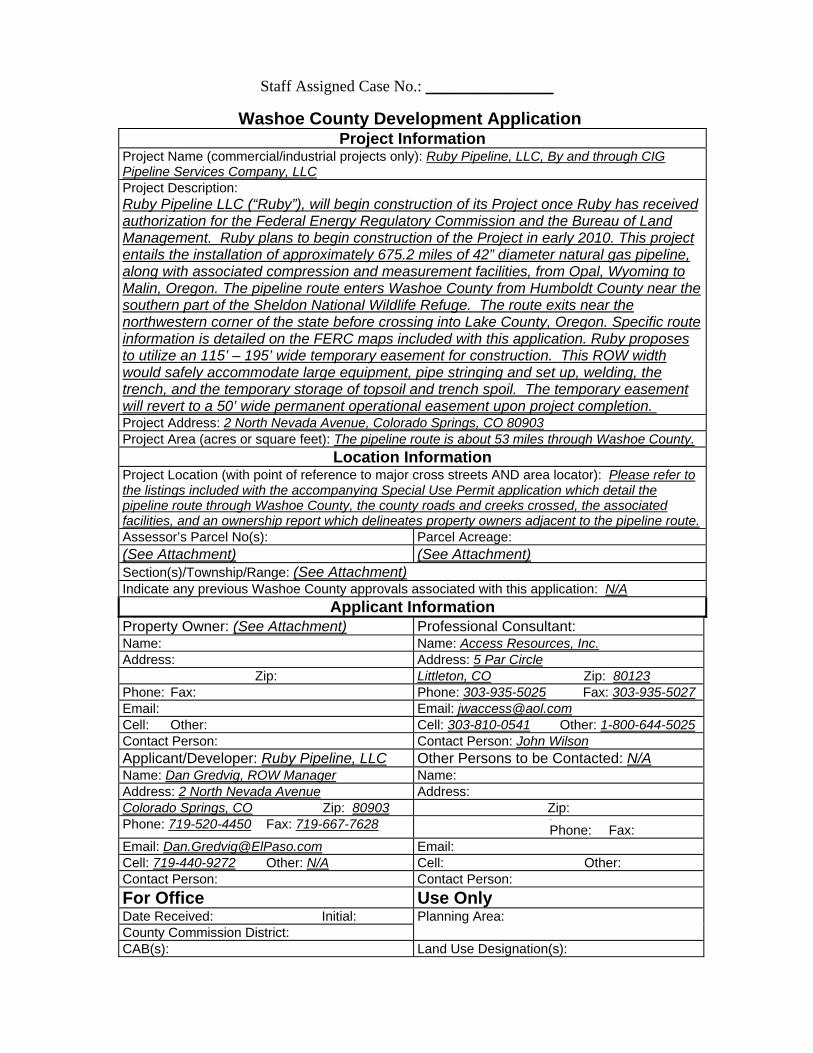
Staff Assigned Case No.: ____________
Washoe County Development Application Project Information
Project Name (commercial/industrial projects only): Ruby Pipeline, LLC, By and through CIG Pipeline Services Company, LLCProject Description: Ruby Pipeline LLC (“Ruby”), will begin construction of its Project once Ruby has received authorization for the Federal Energy Regulatory Commission and the Bureau of Land Management. Ruby plans to begin construction of the Project in early 2010. This project entails the installation of approximately 675.2 miles of 42” diameter natural gas pipeline, along with associated compression and measurement facilities, from Opal, Wyoming to Malin, Oregon. The pipeline route enters Washoe County from Humboldt County near the southern part of the Sheldon National Wildlife Refuge. The route exits near the northwestern corner of the state before crossing into Lake County, Oregon. Specific route information is detailed on the FERC maps included with this application. Ruby proposes to utilize an 115’ – 195’ wide temporary easement for construction. This ROW width would safely accommodate large equipment, pipe stringing and set up, welding, the trench, and the temporary storage of topsoil and trench spoil. The temporary easement will revert to a 50’ wide permanent operational easement upon project completion. Project Address: 2 North Nevada Avenue, Colorado Springs, CO 80903Project Area (acres or square feet): The pipeline route is about 53 miles through Washoe County.
Location Information Project Location (with point of reference to major cross streets AND area locator): Please refer to the listings included with the accompanying Special Use Permit application which detail the pipeline route through Washoe County, the county roads and creeks crossed, the associated facilities, and an ownership report which delineates property owners adjacent to the pipeline route.Assessor’s Parcel No(s): Parcel Acreage: (See Attachment) (See Attachment)Section(s)/Township/Range: (See Attachment)Indicate any previous Washoe County approvals associated with this application: N/A
Applicant Information Property Owner: (See Attachment) Professional Consultant: Name: Name: Access Resources, Inc.Address: Address: 5 Par Circle
Zip: Littleton, CO Zip: 80123Phone: Fax: Phone: 303-935-5025 Fax: 303-935-5027Email: Email: [email protected]: Other: Cell: 303-810-0541 Other: 1-800-644-5025Contact Person: Contact Person: John WilsonApplicant/Developer: Ruby Pipeline, LLC Other Persons to be Contacted: N/AName: Dan Gredvig, ROW Manager Name: Address: 2 North Nevada Avenue Address: Colorado Springs, CO Zip: 80903 Zip: Phone: 719-520-4450 Fax: 719-667-7628 -
Phone: Fax: Email: [email protected] Email: Cell: 719-440-9272 Other: N/A Cell: Other: Contact Person: Contact Person: For Office Use Only Date Received: Initial: Planning Area: County Commission District: CAB(s): Land Use Designation(s):

Director’s Modification Application Supplemental Information
(All required information may be separately attached)
Chapter 110 of the Washoe County Code is commonly known as the Development Code Section 110.410.35 – Modification of Standards allows the Director of Community Development to modify parking standards due to the, “unusual nature” of the establishment proposed. Section 110.412.05(d) – Review of Extenuating Circumstances allows the Director of Community Development to conduct a special review of landscaping standards resulting from “extenuating circumstances or physical conditions” on the proposed project site. 1. What modification to the parking standards are you requesting? Be specific. For example, if this is a parking space modification, how many parking spaces are required and how many are you proposing. If this request is to use decomposed gravel (D.G.) in lieu of asphalt, what is the proposed depth of and compacting of the D.G.? What portion of the parking area will be D.G.? The purpose of this application does not include any modification to parking standards. The Ruby Pipeline Project (Ruby) does not entail any parking spaces. 2. What modification to the landscaping standards are you requesting? Be specific. For example, is this a request to reduce the landscaping from 20% to 15%, or to utilize 50% inert materials at maturation? The modification to the landscaping standards requested entails a formal request to respectfully submit a “Restoration and Revegetation Plan” in lieu of landscaping plans. Please refer to the “Ruby Pipeline Project Restoration and Revegetation Plan for Washoe County, Nevada” which was previously submitted with Ruby Pipeline’s Special Use Permit application on December 15, 2009. The Restoration and Revegetation Plan utilizes reclamation methods as dictated by the Federal Energy Regulatory Commission (FERC). ____________________________________________________________________________________ P:\PLANNING\APPLICATIONS AND FORMS\APPLICATIONS\FY2007-08 July 1, 2007 Page 1

3. Why is the modification necessary to the success of the project? Be specific. Please address the “unusual nature” of the establishment proposed or the “extenuating circumstances or physical conditions” on the proposed project site. The modification is necessary to the success of the project because of the “unusual nature” of the establishment proposed as well as the “extenuating circumstances” on the proposed project site. The Ruby Pipeline Project Right-Of-Way in Washoe County is nearly 53 miles, which is approximately 737 acres with a 115-foot Right-Of-Way. Extra workspaces would disturb approximately 100 acres and access roads would disturb approximately 244 acres. The Ruby Pipeline Project Restoration and Revegetation Plan provides a detailed description of the processes and measures that will be implemented to mitigate the impacts following construction from the Project in Washoe County. This plan is applicable to the Right-Of-Way, extra workspace, and sections of access roads that require reclamation. 4. What exchanges are you proposing to mitigate the effect of the reduction in landscaping, parking or both? (For example planting a specific number of additional trees in exchange for a reduction in required landscape coverage.) To mitigate the effect of the reduction in landscaping, the Ruby Pipeline Restoration and Revegetation Plan proposes detailed short-term and long-term reclamation goals. Short-term reclamation goals entail stabilizing soils by recontouring terrain, spreading stockpiled topsoil, strategically placing erosion control devices, establishing temporary vegetation cover, and abating noxious and invasive weed establishment. Long-term reclamation goals entail establishing a permanent vegetation cover with similar species densities and compositions of adjacent undisturbed lands in accordance with 18 Code of Federal Regulation (CFR) § 380.15 and FERC guidelines. In addition, Ruby will employ multiple restoration measures to meet these short-term and long-term goals including:
QuickTime™ and a decompressor
are needed to see this picture.
____________________________________________________________________________________ P:\PLANNING\APPLICATIONS AND FORMS\APPLICATIONS\FY2007-08 July 1, 2007 Page 2

QuickTime™ and a decompressor
are needed to see this picture.
____________________________________________________________________________________ P:\PLANNING\APPLICATIONS AND FORMS\APPLICATIONS\FY2007-08 July 1, 2007 Page 3
Director’s Modification of Landscaping or Parking Fee Worksheet
Case Number: Project Name: Ruby Pipeline, LLC APN:
Department Fees Community Development 328-6100
$338
Total Fees
$338
Notes 1. In accordance with Nevada Revised Statutes, application fees must be deposited the day of receipt.
This does not guarantee that the application is complete.
Make check payable to Washoe County. Bring check with your application to Community Development.
Submit this page with “Original Packet” only.
Do not include this page in other copies of the packet.
Fees collected per Washoe county Development code, Article 906, Fees.

Draft
Transportation Plan for Use ofWashoe County Public Access
Roads
FERC Docket No. CP09-54-000
January 2010

RUBY PIPELINE PROJECT DRAFT TRANSPORTATION PLAN FOR USE OFWASHOE COUNTY PUBLIC ACCESS ROADS
i January 2010
Table of Contents
Section Page
1.0 Introduction ..............................................................................1-1
2.0 Proposed Use of Roads and Vya Camp..................................2-12.1 Location and Characteristics of Roads and Routes Proposed for
Use ...................................................................................................... 2-12.2 Proposed Duration and Intensity of Road Use .................................... 2-12.3 Proposed Vya Camp Manpower Usage .............................................. 2-7
3.0 Environmental Analysis and Terms of Access ......................3-13.1 Environmental Analysis of Roads........................................................ 3-13.2 Safety Analysis .................................................................................... 3-1
4.0 Summary...................................................................................4-1
5.0 References................................................................................5-1
A Figures..................................................................................... A-1

RUBY PIPELINE PROJECT DRAFT TRANSPORTATION PLAN FOR USE OFWASHOE COUNTY PUBLIC ACCESS ROADS
ii January 2010
List of Tables
Table Page
Table 2.2-1 Washoe County Road Use Prior to Start of Initial Construction –Approximate Begin Date: May 1, 2010................................................ 2-1
Table 2.2-2 Washoe County Road Use after Start of Construction -Approximate Start Date: Rockford - June 1, 2010. PrecisionPipeline – August 1, 2010.................................................................... 2-3
Table 2.2-3 Washoe County Road Use After Construction – Demobilization forPrecision Pipeline - Approximate Begin Date: December 15, 2010 .... 2-6
Table 2.2-4 Initial Equipment and Number of Vehicles Needed for UploadingPipe at Gerlach Yard ........................................................................... 2-6
Table 2.2-5 Number of Vehicles for Mobilizing Pipe from Gerlach to Vya,.............. 2-7Table 2.3-1 Combine Rockford and Precision Manpower....................................... 2-7

RUBY PIPELINE PROJECT DRAFT TRANSPORTATION PLAN FOR USE OFWASHOE COUNTY PUBLIC ACCESS ROADS
iii January 2010
List of Figures
Figure Page
Figure A1 Washoe County Access Road .............................................................A-2
RUBY PIPELINE PROJECT DRAFT TRANSPORTATION PLAN FOR USE OFWASHOE COUNTY PUBLIC ACCESS ROADS
iv January 2010
List of Abbreviations and Acronyms
BLM Bureau of Land Management
FERC Federal Energy Regulatory Commission
Project Ruby Pipeline Project
ROW Right-of-Way
Ruby Ruby Pipeline, LLC
Sheldon NWR Charles Sheldon National Wildlife Refuge
RUBY PIPELINE PROJECT DRAFT TRANSPORTATION PLAN FOR USE OFWASHOE COUNTY PUBLIC ACCESS ROADS
1-1 January 2010
1.0 Introduction
The Ruby Pipeline Project (Project), proposed by Ruby Pipeline, LLC (Ruby), is composed of
approximately 675.2 miles of 42-inch diameter natural gas pipeline, along with associated
compression and measurement facilities, located between Opal, Wyoming, and Malin, Oregon.
The Project includes an approximate 2.6-mile lateral, to be constructed from the pipeline
termination point north to the Malin Hub in Klamath County, Oregon. The pipeline right-of-way
(ROW) would cross four states: Wyoming, Utah, Nevada, and Oregon.
The proposed route for the ROW would cross northern Nevada primarily in an east-to-west
direction and in western Washoe County it will traverse in a south-to-north direction. The route
within Washoe County passes through lands managed by the Bureau of Land Management
(BLM) lands and private lands. Part of the route would run approximately 1 to 1.5 miles south of
Charles Sheldon National Wildlife Refuge (Sheldon NWR), which is managed by the U.S. Fish
and Wildlife Service. This transportation plan has been developed specifically for use of County
Public Access Roads that will be used during the construction of the Project within Washoe
County. In addition, the Vya Camp manpower usage has been included in this plan.

RUBY PIPELINE PROJECT DRAFT TRANSPORTATION PLAN FOR USE OFWASHOE COUNTY PUBLIC ACCESS ROADS
2-1 January 2010
2.0 Proposed Use of Roads and Vya Camp
2.1 Location and Characteristics of Roads and Routes Proposed for
Use
State Route 34 and County Road 8A are unpaved but improved with grading and cut drainage
ditches. Ruby proposes to use existing public roads to access the Project. However, as
approved by landowner of record, Ruby would also use private roads. Roads within Washoe
County that are proposed for Ruby construction vehicle use during pipeline construction are
shown in Figure A-1.
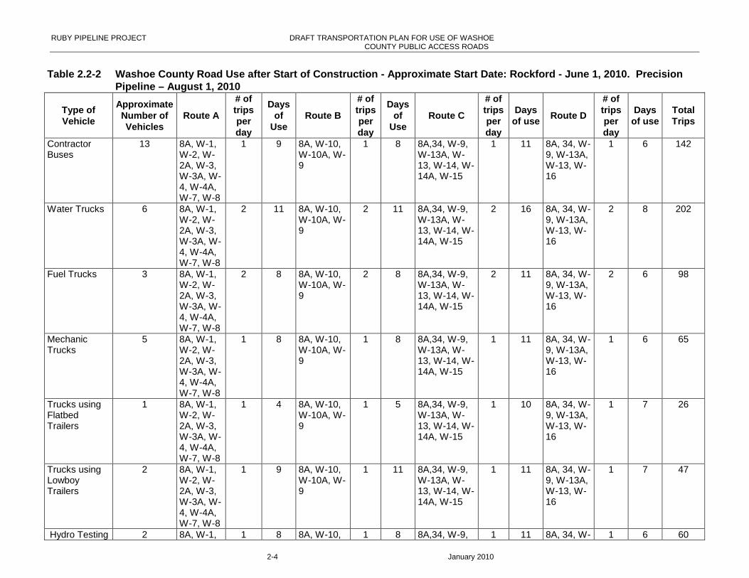
2.2 Proposed Duration and Intensity of Road Use
Construction of the Project would move progressively east to west and south to north along the
ROW at approximately one mile a day. Ruby and its construction contractors will generally haul
legal loads across Washoe County Public Access Roads. These roads would be used for
approximately eight months, from May through December. The vehicle count would vary from
day to day. For the months before and after construction, the volume of traffic on the roads
would be less. Use prior to initial construction (May) would be for the construction companies to
stage equipment as well as for foreman, surveyors and environmental monitors to inspect and
survey the Certificated ROW. Higher volume of vehicles on the roads would occur from
approximately early August through early to mid November. After construction (December),
construction companies would be using roads for revegetation and final clean-up. Construction
should be complete by the end of December 2010. Tables 2.2-1 through 2.2-3 lists the types
and the potential numbers of vehicles that would use the access roads on a daily basis. Ruby’s
construction contractor will apply for any permits for over length, width, or weight loads that will
cross Washoe County Public Access Roads.
Table 2.2-1 Washoe County Road Use Prior to Start of Initial Construction –Approximate Begin Date: May 1, 2010
Type of VehicleApproximateNumber ofVehicles
Routes# of
trips perday
Daysof
use
TotalTrips
Stringing Trucks 20 8A, 34 1 1 20Welding Rigs 25 8A, 34 1 1 25Inspector, survey, foreman Vehicles 28 8A,W9,W13,
W15,W16,34A
1 30 840
Environmental and Cultural MonitorVehicles
15 8A,W9,W13,W15,W16,
34A
1 30 450
Contractor Vehicles 40 8A, 34 1 2 80Contractor Buses 13 8A, 34 1 1 13Water Trucks 6 8A, 34 1 1 6Fuel Trucks 3 8A, 34 1 1 3

RUBY PIPELINE PROJECT DRAFT TRANSPORTATION PLAN FOR USE OF ACCESS ROADSIN WASHOE COUNTY
2-2 January 2010
Table 2.2-1 Washoe County Road Use Prior to Start of Initial Construction –Approximate Begin Date: May 1, 2010
Type of VehicleApproximateNumber ofVehicles
Routes# of
trips perday
Daysof
use
TotalTrips
Mechanic Trucks 5 8A, 34 1 1 5Trucks using Flatbed Trailers 10 8A, 34 1 13 130Trucks using Lowboy Trailers 10 8A, 34 1 9 90Hydro Testing Equipment/Dryers andCompressors
4 8A, 34 2 2 16
Motor Graders 2 8A, 34 1 2 4
Total 33 377

RUBY PIPELINE PROJECT DRAFT TRANSPORTATION PLAN FOR USE OF WASHOE COUNTY PUBLIC ACCESS ROADS
2-3 January 2010
Table 2.2-2 Washoe County Road Use after Start of Construction - Approximate Start Date: Rockford - June 1, 2010. PrecisionPipeline – August 1, 2010
Type ofVehicle
ApproximateNumber ofVehicles
Route A
# oftripsperday
Daysof
UseRoute B
# oftripsperday
Daysof
UseRoute C
# oftripsperday
Daysof use
Route D
# oftripsperday
Daysof use
TotalTrips
Foreman PU's 10 8A, W-1,W-2, W-2A, W-3,W-3A, W-4, W-4A,W-7, W-8
1 22 8A, W-10,W-10A, W-9
1 22 8A,34, W-9,W-13A, W-13, W-14, W-14A, W-15
1 22 8A, 34, W-9, W-13A,W-13, W-16
1 6 270
StringingTrucks
20 8A, W-1,W-2, W-2A, W-3,W-3A, W-4, W-4A,W-7, W-8
2 8 8A, W-10,W-10A, W-9
2 8 8A,34, W-9,W-13A, W-13, W-14, W-14A, W-15
1 15 8A, 34, W-9, W-13A,W-13, W-16
1 10 1065
Welding Rigs 25 8A, W-1,W-2, W-2A, W-3,W-3A, W-4, W-4A,W-7, W-8
1 8 8A, W-10,W-10A, W-9
1 8 8A,34, W-9,W-13A, W-13, W-14, W-14A, W-15
1 11 8A, 34, W-9, W-13A,W-13, W-16
1 6 225
InspectorVehicles
28 8A, W-1,W-2, W-2A, W-3,W-3A, W-4, W-4A,W-7, W-8
1 8 8A, W-10,W-10A, W-9
1 8 8A,34, W-9,W-13A, W-13, W-14, W-14A, W-15
1 11 8A, 34, W-9, W-13A,W-13, W-16
1 6 249
Environmentaland CulturalMonitorVehicles
10 8A, W-1,W-2, W-2A, W-3,W-3A, W-4, W-4A,W-7, W-8
1 8 8A, W-10,W-10A, W-9
1 8 8A,34, W-9,W-13A, W-13, W-14, W-14A, W-15
1 11 8A, 34, W-9, W-13A,W-13, W-16
1 6 105
ContractorVehicles(other)
40 8A, W-1,W-2, W-2A, W-3,W-3A, W-4, W-4A,W-7, W-8
1 8 8A, W-10,W-10A, W-9
1 8 8A,34, W-9,W-13A, W-13, W-14, W-14A, W-15
1 11 8A, 34, W-9, W-13A,W-13, W-16
1 6 345
RUBY PIPELINE PROJECT DRAFT TRANSPORTATION PLAN FOR USE OF WASHOECOUNTY PUBLIC ACCESS ROADS
2-4 January 2010
Table 2.2-2 Washoe County Road Use after Start of Construction - Approximate Start Date: Rockford - June 1, 2010. PrecisionPipeline – August 1, 2010
Type ofVehicle
ApproximateNumber ofVehicles
Route A
# oftripsperday
Daysof
UseRoute B
# oftripsperday
Daysof
UseRoute C
# oftripsperday
Daysof use
Route D
# oftripsperday
Daysof use
TotalTrips
ContractorBuses
13 8A, W-1,W-2, W-2A, W-3,W-3A, W-4, W-4A,W-7, W-8
1 9 8A, W-10,W-10A, W-9
1 8 8A,34, W-9,W-13A, W-13, W-14, W-14A, W-15
1 11 8A, 34, W-9, W-13A,W-13, W-16
1 6 142
Water Trucks 6 8A, W-1,W-2, W-2A, W-3,W-3A, W-4, W-4A,W-7, W-8
2 11 8A, W-10,W-10A, W-9
2 11 8A,34, W-9,W-13A, W-13, W-14, W-14A, W-15
2 16 8A, 34, W-9, W-13A,W-13, W-16
2 8 202
Fuel Trucks 3 8A, W-1,W-2, W-2A, W-3,W-3A, W-4, W-4A,W-7, W-8
2 8 8A, W-10,W-10A, W-9
2 8 8A,34, W-9,W-13A, W-13, W-14, W-14A, W-15
2 11 8A, 34, W-9, W-13A,W-13, W-16
2 6 98
MechanicTrucks
5 8A, W-1,W-2, W-2A, W-3,W-3A, W-4, W-4A,W-7, W-8
1 8 8A, W-10,W-10A, W-9
1 8 8A,34, W-9,W-13A, W-13, W-14, W-14A, W-15
1 11 8A, 34, W-9, W-13A,W-13, W-16
1 6 65
Trucks usingFlatbedTrailers
1 8A, W-1,W-2, W-2A, W-3,W-3A, W-4, W-4A,W-7, W-8
1 4 8A, W-10,W-10A, W-9
1 5 8A,34, W-9,W-13A, W-13, W-14, W-14A, W-15
1 10 8A, 34, W-9, W-13A,W-13, W-16
1 7 26
Trucks usingLowboyTrailers
2 8A, W-1,W-2, W-2A, W-3,W-3A, W-4, W-4A,W-7, W-8
1 9 8A, W-10,W-10A, W-9
1 11 8A,34, W-9,W-13A, W-13, W-14, W-14A, W-15
1 11 8A, 34, W-9, W-13A,W-13, W-16
1 7 47
Hydro Testing 2 8A, W-1, 1 8 8A, W-10, 1 8 8A,34, W-9, 1 11 8A, 34, W- 1 6 60

RUBY PIPELINE PROJECT DRAFT TRANSPORTATION PLAN FOR USE OF WASHOECOUNTY PUBLIC ACCESS ROADS
2-5 January 2010
Table 2.2-2 Washoe County Road Use after Start of Construction - Approximate Start Date: Rockford - June 1, 2010. PrecisionPipeline – August 1, 2010
Type ofVehicle
ApproximateNumber ofVehicles
Route A
# oftripsperday
Daysof
UseRoute B
# oftripsperday
Daysof
UseRoute C
# oftripsperday
Daysof use
Route D
# oftripsperday
Daysof use
TotalTrips
Equipment/Dryers andCompressors
W-2, W-2A, W-3,W-3A, W-4, W-4A,W-7, W-8
W-10A, W-9
W-13A, W-13, W-14, W-14A, W-15
9, W-13A,W-13, W-16
Motor Graders 2 8A, W-1,W-2, W-2A, W-3,W-3A, W-4, W-4A,W-7, W-8
1 12 8A, W-10,W-10A, W-9
1 15 8A,34, W-9,W-13A, W-13, W-14, W-14A, W-15
1 15 8A, 34, W-9, W-13A,W-13, W-16
1 10 104
Total 167 131 146 177 96 3003

RUBY PIPELINE PROJECT DRAFT TRANSPORTATION PLAN FOR USE OFWASHOECOUNTY PUBLIC ACCESS ROADS
2-6 January 2010
Table 2.2-3 Washoe County Road Use After Construction – Demobilization forPrecision Pipeline - Approximate Begin Date: December 15, 2010
Type of VehicleApproximateNumber ofVehicles
Routes
# oftrips
per dayDays of
useTotalTrips
Stringing Trucks 20 34, 8A 1 1 20Welding Rigs 25 34, 8A 1 1 25Inspector, survey, foremanVehicles
2834, 8A 1 2 56
Environmental and CulturalMonitor Vehicles
1534, 8A 1 2 30
Contractor Vehicles (other) 40 34, 8A 1 2 80Contractor Buses 13 34, 8A 1 1 13Water Trucks 6 34, 8A 1 1 6Fuel Trucks 3 34, 8A 1 1 3Mechanic Trucks 5 34, 8A 1 1 5Trucks using Flatbed Trailers 10 34, 8A 1 13 130Trucks using Lowboy Trailers 10 34, 8A 1 13 130Hydro Testing Equipment/Dryersand Compressors
434, 8A 2 2 16
Motor Graders 2 34, 8A 1 2 4
Total 42 518
Gerlach, Nevada Traffic Plan for Pipe Unloading
PeBen, USA has been contracted to coordinate the logistics of arranging rail cars andunloading steel pipe produced at Welspun and Berg Pipe.
As part of the Logistics Contract, PeBen will pursue the necessary permits required forreceiving the pipe at Gerlach, Nevada; preparing the yard for storage of the pipe; and physicallyunloading the rail cars and racking the pipe. The first rail shipment from the pipe mills toGerlach is expected to occur in mid to late February, 2010. PeBen requires several days toprepare the yard for pipe storage.
Table 2.2-4 Initial Equipment and Number of Vehicles Needed for UploadingPipe at Gerlach Yard
Type of Vehicle Approximate Number of Vehicles
450 JD excavators with vacuum lift attachment 2Cat D-6 dozer 1Manlift 1Stringing trucks 4Pickups 3
The route all trucks would take to access Gerlach would be I-80 to State Route 447, north to Gerlach.
Four lowboys will haul the excavators, the bulldozer, and the manlift. During the course ofunloading and racking the pipe, the only vehicles to enter public roads will be the pickupsgetting from the yard to a motel, recreational vehicle, or restaurant each day. The duration ofunloading is expected to take 1.5 to 2 months working 5 or 6 days per week. At the end ofunloading and racking, PeBen will demobilize the unloading crew.

RUBY PIPELINE PROJECT DRAFT TRANSPORTATION PLAN FOR USE OFWASHOE
COUNTY PUBLIC ACCESS ROADS
2-7 January 2010
Transportation of Pipe from Gerlach to Stringing Yard East of VyaTransportation of the pipe from Gerlach inventory yard to the Federal Energy RegulatoryCommission (FERC) -filed stringing yard approximately 5 miles east of Vya would begin uponreceipt of the FERC certificate and the Notice to Proceed. Ruby expects this approval on orabout March 15, 2010. PeBen anticipates receipt up to 65 miles of 42" diameter pipe into theGerlach yard beginning mid to late February, 2010. Depending on the rail delivery from thepipe mills, PeBen could expect to receive 9 to 10 deliveries per week into Gerlach. Starting inmid to late March, PeBen would begin trucking the pipe from Gerlach to Vya. The 65 miles willbe comprised of 50% light wall and 50% heavy wall pipe.
Table 2.2-5 Number of Vehicles for Mobilizing Pipe from Gerlach to Vya,
Type of VehicleApproximate# of Vehicles
#of round tripsper day
Days of use
Stringing trucks 16 2 56Joints/truck (light wall pipe) 3 715 (for the 32.5
miles)56
Joints/truck (heavy wall pipe) 2 1,073 (for the32.5 miles)
56
Total 56
PeBen plans to use two different routes for the pipe delivery. Route one is Hwy 447 throughGerlach to State Route 34 to Nevada 8A. Route two is Hwy 447 through Gerlach to SurpriseValley Road through Cedarville, California to Hwy 299, then east on 299 to Nevada 8A.
2.3 Proposed Vya Camp Manpower Usage
For the construction of spreads 4B and 6A in northwestern Nevada, construction companiesRockford and Precision will be utilizing the Vya Camp. Rockford proposes to mobilize in midApril through the beginning of November. Precision proposes to mobilize mid August throughthe end of January 2011. Table 2.3-1 and the graph following the table represent the numberof workers utilizing the Vya Camp.
Table 2.3-1 Combine Rockford and Precision Manpower
Rockford (6A)Precision (4B)
Date Number of Personal Date Number of Personal
4/18/2010 5 8/22/2010 0
4/25/2010 9 8/29/2010 46
5/2/2010 14 9/5/2010 125
5/9/2010 27 9/12/2010 270
5/16/2010 27 9/19/2010 372
RUBY PIPELINE PROJECT DRAFT TRANSPORTATION PLAN FOR USE OFWASHOE
COUNTY PUBLIC ACCESS ROADS
2-8 January 2010
Table 2.3-1 Combine Rockford and Precision Manpower
Rockford (6A)Precision (4B)
Date Number of Personal Date Number of Personal
5/23/2010 60 9/26/2010 532
5/30/2010 91 10/3/2010 532
6/6/2010 125 10/10/2010 532
6/13/2010 232 10/17/2010 532
6/20/2010 246 10/24/2010 537
6/27/2010 269 10/31/2010 537
7/4/2010 352 11/7/2010 440
7/11/2010 475 11/14/2010 388
7/18/2010 471 11/21/2010 310
7/25/2010 516 11/28/2010 270
8/1/2010 453 12/5/2010 210
8/8/2010 395 12/12/2010 188
8/15/2010 252 12/19/2010 20
8/22/2010 185 12/26/2010 20
8/29/2010 136 1/2/2011 20
9/5/2010 93 1/9/2011 20
9/12/2010 119 1/16/2011 10
9/19/2010 99 1/23/2011 0
9/26/2010 82
10/3/2010 82
10/10/2010 82
RUBY PIPELINE PROJECT DRAFT TRANSPORTATION PLAN FOR USE OFWASHOE
COUNTY PUBLIC ACCESS ROADS
2-9 January 2010
Table 2.3-1 Combine Rockford and Precision Manpower
Rockford (6A)Precision (4B)
Date Number of Personal Date Number of Personal
10/17/2010 28
10/24/2010 18
10/31/2010 9
11/7/2010 0

RUBY PIPELINE PROJECT DRAFT TRANSPORTATION PLAN FOR USE OFWASHOE
COUNTY PUBLIC ACCESS ROADS
2-10 January 2010
Combined Rockford - Precision manpower
5 91
42
72
76
09
11
25
23
22
46
26
93
52
47
54
71
51
64
53
39
52
52
18
51
36
93
11
9 99 8
28
28
22
8 18 9 00
46
12
52
70
37
25
32
53
25
32
53
25
37
53
74
40
38
83
10
27
02
10 1
88
20
20
20
20 1
00
0
100
200
300
400
500
600
3/2
3/2
01
0
4/1
2/2
01
0
5/2
/20
10
5/2
2/2
01
0
6/1
1/2
01
0
7/1
/20
10
7/2
1/2
01
0
8/1
0/2
01
0
8/3
0/2
01
0
9/1
9/2
01
0
10
/9/2
01
0
10
/29
/20
10
11
/18
/20
10
12
/8/2
01
0
12
/28
/20
10
1/1
7/2
01
1
2/6
/20
11
Date
Rockford
Precision
RUBY PIPELINE PROJECT DRAFT TRANSPORTATION PLAN FOR USE OFWASHOECOUNTY PUBLIC ACCESS ROADS
3-1 January 2010
3.0 Environmental Analysis and Terms of Access
3.1 Environmental Analysis of Roads
Unpaved public roads require periodic maintenance to repair ruts, potholes, and sags. Regular
maintenance is even more important on unpaved roads used by vehicles with heavy axle loads.
The following maintenance measures listed below will ensure public access roads are left in
good condition:
At the direction of the Washoe County Road and Bridge Supervisor Ruby will:
o During construction activities, provide appropriate ongoing maintenance to
Washoe County Public Access Roads
o Immediately after construction, will inspect the roads with the Washoe County
Road and Bridge Supervisor to determine if road repair is required
Prior to construction, Ruby will photograph all Washoe County culverts, bridges and cattle
guards crossed by Ruby’s construction access.
o These photographs will provide a baseline for determining if any damage has
occurred during Ruby construction activities.
o If culverts, bridges or cattle guards are damaged as a result of Ruby’s
construction activities Ruby will be responsible for insuring the appropriate
repairs are made to County standards
If required prior to use, public access roads will be bladed to ensure a properly shaped and
graded road surface to eliminate potential for standing water on the road. This would help
prevent ruts and potholes. Ruby will be responsible for any damages caused to Washoe
County Public Access Roads as a result of project construction, operation and maintenance
activities.
3.2 Safety Analysis
The ability of the roads within Washoe County to safely accommodate an increase in traffic
must be considered in Ruby’s analysis of access roads and routes for the Project. Along
County Road 8A, there are blind corners that Sheldon NWR, and the Nevada Department of
Transportation have identified as a safety risk. An increase in traffic on public roads would
further increase the danger at these blind corners. Such safety concerns would be mitigated by
mowing vegetation up to 10 feet up the side slope to give 100 feet of visibility, where feasible,
as well as placing caution and speed limit signs.
Additionally, Public Access Roads in Washoe County are unpaved, and unpaved roads are
dangerous when wet. A wet, unpaved road can have the same traction as an ice-covered road
(USDOI NPS May 2009). Unpaved roads can also become muddy when wet, and vehicles
RUBY PIPELINE PROJECT DRAFT TRANSPORTATION PLAN FOR USE OFWASHOE
COUNTY PUBLIC ACCESS ROADS
3-2 January 2010
driving on them risk becoming stuck, especially if they are heavy or do not have four-wheel
drive. In the fall, winter, and spring, unpaved roads may be impassable due to snow drifts.
Along County Road 8A, there are portions of the road where gravel has worn away; Ruby would
alleviate any damage to these sections by performing pre-construction maintenance and
continual assessment/maintenance of the road during construction. During rain and/or snow
conditions, unpaved roads or areas where gravel has worn away will rut when driven on. If road
conditions become unsafe on the access roads or excessive ruts are created then Ruby will use
the pipeline ROW or will cease the use of these roads/routes until rutting is no longer a concern
or Ruby installs gravel to prevent rutting. In addition, Ruby will employ the following
maintenance measures at the Washoe County’s Road and Bridge Supervisors direction:
o Suspend use of County Roads if the road condition becomes unsafe for public
use.
Ruby will have the opportunity to gravel, maintain or limit traffic on these
roads to address these safety concerns.
o Install appropriate warning signs along the Washoe County Public Access Roads
used during Ruby’s construction activities
o Apply appropriate dust control measures on Washoe County Public Access
Roads in the vicinity of homes or building that are being adversely affected by
dust that is created by Ruby’s construction activities
RUBY PIPELINE PROJECT DRAFT TRANSPORTATION PLAN FOR USE OF ASHOECOUNTY PUBLIC ACCESS ROADS
4-1 January 2010
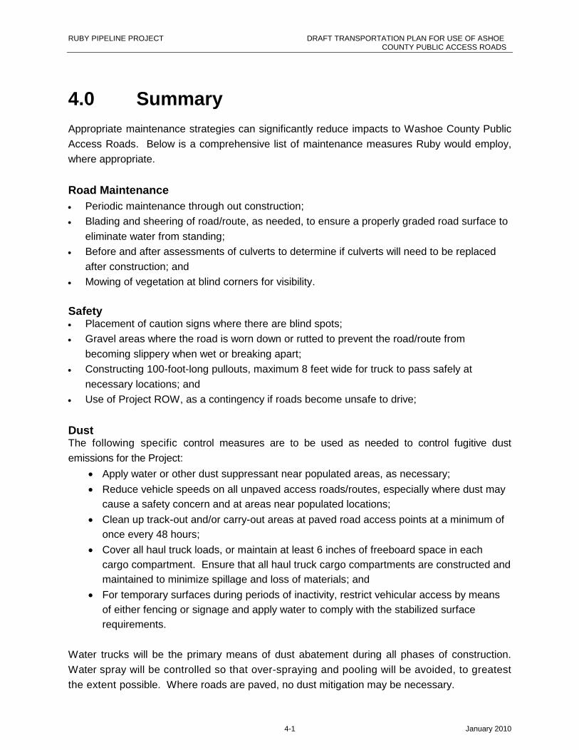
4.0 Summary
Appropriate maintenance strategies can significantly reduce impacts to Washoe County Public
Access Roads. Below is a comprehensive list of maintenance measures Ruby would employ,
where appropriate.
Road Maintenance
Periodic maintenance through out construction;
Blading and sheering of road/route, as needed, to ensure a properly graded road surface to
eliminate water from standing;
Before and after assessments of culverts to determine if culverts will need to be replaced
after construction; and
Mowing of vegetation at blind corners for visibility.
Safety Placement of caution signs where there are blind spots;
Gravel areas where the road is worn down or rutted to prevent the road/route from
becoming slippery when wet or breaking apart;
Constructing 100-foot-long pullouts, maximum 8 feet wide for truck to pass safely at
necessary locations; and
Use of Project ROW, as a contingency if roads become unsafe to drive;
DustThe following specific control measures are to be used as needed to control fugitive dust
emissions for the Project:
Apply water or other dust suppressant near populated areas, as necessary;
Reduce vehicle speeds on all unpaved access roads/routes, especially where dust may
cause a safety concern and at areas near populated locations;
Clean up track-out and/or carry-out areas at paved road access points at a minimum of
once every 48 hours;
Cover all haul truck loads, or maintain at least 6 inches of freeboard space in each
cargo compartment. Ensure that all haul truck cargo compartments are constructed and
maintained to minimize spillage and loss of materials; and
For temporary surfaces during periods of inactivity, restrict vehicular access by means
of either fencing or signage and apply water to comply with the stabilized surface
requirements.
Water trucks will be the primary means of dust abatement during all phases of construction.
Water spray will be controlled so that over-spraying and pooling will be avoided, to greatest
the extent possible. Where roads are paved, no dust mitigation may be necessary.

RUBY PIPELINE PROJECT DRAFT TRANSPORTATION PLAN FOR USE OF ASHOECOUNTY PUBLIC ACCESS ROADS
5-1 January 2010
5.0 References
United States Department of the Interior, National Park Service (USDOI NPS). May 2009.
Your Safety. May 1, 2009. http://www.nps.gov/badl/planyourvisit/yoursafety.htm (Accessed
in August 2009).

RUBY PIPELINE PROJECT DRAFT TRANSPORTATION PLAN FOR USE OF ASHOECOUNTY PUBLIC ACCESS ROADS
A-1 January 2010
A Figures

!(
!(!(!(
!(!(
!(
!(
!(
!(
!(!(
_̂
_̂
Sheldon NationalWildlife Refuge
UV447
UV49
UV81
UV140
UV299
UV34
UV34A
UV139
UV8A
UV8A
£¤395
PERSHINGCOUNTY
WASHOECOUNTY
LAKECOUNTY
LASSENCOUNTY
MODOCCOUNTY
HUMBOLDTCOUNTY
HARNEYCOUNTY
CCaa ll
ii ffoo rr
nnii aa
NNee vv
aa ddaa
140
L-1AL-1D
H-51
H-40
H-42
H-41
L-15E L-1F
L-1B
H-48H-50 H-43
L-4
H-45
H-46
L-15
W-9
W-9
W-16
W-15
W-3W-
13
W-15
8a
510520
630
590
580
570
560550
540530
GERLACH
VYA
\\Prtbhp1\gis\Portland\Ruby_Pipeline\Maps\PDFs\Phase_2\Sheldon_Alternative\SheldonTransportationPlanReportFigures\WashoeCountyOverview_Sheldon_8.5x11.mxd 12/22/2009
!( MilepostProposed Route Major RoadWashoe County Access RoadsSheldon National Wildlife Refuge
Figure A1Washoe County
Access Roads OverviewRuby Pipeline Project
December 2009
N VN V
I DI D
U TU T
O RO R
C AC A
W YW Y
0 5 10
Miles±

Home Page > Executive Branch > Code of Federal Regulations > Electronic Code of Federal Regulations
e-CFR Data is current as of January 4, 2010
Title 49: TransportationPART 192—TRANSPORTATION OF NATURAL AND OTHER GAS BY PIPELINE: MINIMUM FEDERAL SAFETY STANDARDS
Browse Next
Subpart A—General
§ 192.1 What is the scope of this part?
(a) This part prescribes minimum safety requirements for pipeline facilities and the transportation of gas,including pipeline facilities and the transportation of gas within the limits of the outer continental shelf asthat term is defined in the Outer Continental Shelf Lands Act (43 U.S.C. 1331).
(b) This part does not apply to—
(1) Offshore gathering of gas in State waters upstream from the outlet flange of each facility wherehydrocarbons are produced or where produced hydrocarbons are first separated, dehydrated, or otherwiseprocessed, whichever facility is farther downstream;
(2) Pipelines on the Outer Continental Shelf (OCS) that are producer-operated and cross into State waterswithout first connecting to a transporting operator's facility on the OCS, upstream (generally seaward) ofthe last valve on the last production facility on the OCS. Safety equipment protecting PHMSA-regulatedpipeline segments is not excluded. Producing operators for those pipeline segments upstream of the lastvalve of the last production facility on the OCS may petition the Administrator, or designee, for approvalto operate under PHMSA regulations governing pipeline design, construction, operation, and maintenanceunder 49 CFR 190.9;
(3) Pipelines on the Outer Continental Shelf upstream of the point at which operating responsibilitytransfers from a producing operator to a transporting operator;
(4) Onshore gathering of gas—
(i) Through a pipeline that operates at less than 0 psig (0 kPa);
(ii) Through a pipeline that is not a regulated onshore gathering line (as determined in §192.8); and
(iii) Within inlets of the Gulf of Mexico, except for the requirements in §192.612; or
(5) Any pipeline system that transports only petroleum gas or petroleum gas/air mixtures to—

(i) Fewer than 10 customers, if no portion of the system is located in a public place; or
(ii) A single customer, if the system is located entirely on the customer's premises (no matter if a portion ofthe system is located in a public place).
[35 FR 13257, Aug. 19, 1970, as amended by Amdt. 192–27, 41 FR 34605, Aug. 16, 1976; Amdt. 192–67,56 FR 63771, Dec. 5, 1991; Amdt. 192–78, 61 FR 28782, June 6, 1996; Amdt. 192–81, 62 FR 61695, Nov.19, 1997; Amdt. 192–92, 68 FR 46112, Aug. 5, 2003; 70 FR 11139, Mar. 8, 2005; Amdt. 192–102, 71 FR13301, Mar. 15, 2006; Amdt. 192–103, 72 FR 4656, Feb. 1, 2007]
§ 192.3 Definitions.
Link to an amendment published at 74 FR 63326, December 3, 2009.
As used in this part:
Abandoned means permanently removed from service.
Administrator means the Administrator, Pipeline and Hazardous Materials Safety Administration or his orher delegate.
Customer meter means the meter that measures the transfer of gas from an operator to a consumer.
Distribution line means a pipeline other than a gathering or transmission line.
Exposed underwater pipeline means an underwater pipeline where the top of the pipe protrudes above theunderwater natural bottom (as determined by recognized and generally accepted practices) in waters lessthan 15 feet (4.6 meters) deep, as measured from mean low water.
Gas means natural gas, flammable gas, or gas which is toxic or corrosive.
Gathering line means a pipeline that transports gas from a current production facility to a transmission lineor main.
Gulf of Mexico and its inlets means the waters from the mean high water mark of the coast of the Gulf ofMexico and its inlets open to the sea (excluding rivers, tidal marshes, lakes, and canals) seaward to includethe territorial sea and Outer Continental Shelf to a depth of 15 feet (4.6 meters), as measured from themean low water.
Hazard to navigation means, for the purposes of this part, a pipeline where the top of the pipe is less than12 inches (305 millimeters) below the underwater natural bottom (as determined by recognized andgenerally accepted practices) in waters less than 15 feet (4.6 meters) deep, as measured from the mean lowwater.
High-pressure distribution system means a distribution system in which the gas pressure in the main ishigher than the pressure provided to the customer.
Line section means a continuous run of transmission line between adjacent compressor stations, between acompressor station and storage facilities, between a compressor station and a block valve, or betweenadjacent block valves.
Listed specification means a specification listed in section I of appendix B of this part.
Low-pressure distribution system means a distribution system in which the gas pressure in the main issubstantially the same as the pressure provided to the customer.
Main means a distribution line that serves as a common source of supply for more than one service line.
Maximum actual operating pressure means the maximum pressure that occurs during normal operationsover a period of 1 year.
Maximum allowable operating pressure (MAOP) means the maximum pressure at which a pipeline orsegment of a pipeline may be operated under this part.
Municipality means a city, county, or any other political subdivision of a State.
Offshore means beyond the line of ordinary low water along that portion of the coast of the United Statesthat is in direct contact with the open seas and beyond the line marking the seaward limit of inland waters.
Operator means a person who engages in the transportation of gas.
Outer Continental Shelf means all submerged lands lying seaward and outside the area of lands beneathnavigable waters as defined in Section 2 of the Submerged Lands Act (43 U.S.C. 1301) and of which thesubsoil and seabed appertain to the United States and are subject to its jurisdiction and control.
Person means any individual, firm, joint venture, partnership, corporation, association, State, municipality,cooperative association, or joint stock association, and including any trustee, receiver, assignee, orpersonal representative thereof.
Petroleum gas means propane, propylene, butane, (normal butane or isobutanes), and butylene (includingisomers), or mixtures composed predominantly of these gases, having a vapor pressure not exceeding 208psi (1434 kPa) gage at 100 °F (38 °C).
Pipe means any pipe or tubing used in the transportation of gas, including pipe-type holders.
Pipeline means all parts of those physical facilities through which gas moves in transportation, includingpipe, valves, and other appurtenance attached to pipe, compressor units, metering stations, regulatorstations, delivery stations, holders, and fabricated assemblies.
Pipeline facility means new and existing pipelines, rights-of-way, and any equipment, facility, or buildingused in the transportation of gas or in the treatment of gas during the course of transportation.
Service line means a distribution line that transports gas from a common source of supply to an individualcustomer, to two adjacent or adjoining residential or small commercial customers, or to multiple residentialor small commercial customers served through a meter header or manifold. A service line ends at the outletof the customer meter or at the connection to a customer's piping, whichever is further downstream, or atthe connection to customer piping if there is no meter.
Service regulator means the device on a service line that controls the pressure of gas delivered from ahigher pressure to the pressure provided to the customer. A service regulator may serve one customer ormultiple customers through a meter header or manifold.
SMYS means specified minimum yield strength is:
(1) For steel pipe manufactured in accordance with a listed specification, the yield strength specified as a
minimum in that specification; or
(2) For steel pipe manufactured in accordance with an unknown or unlisted specification, the yield strengthdetermined in accordance with §192.107(b).
State means each of the several States, the District of Columbia, and the Commonwealth of Puerto Rico.
Transmission line means a pipeline, other than a gathering line, that: (1) Transports gas from a gatheringline or storage facility to a distribution center, storage facility, or large volume customer that is not down-stream from a distribution center; (2) operates at a hoop stress of 20 percent or more of SMYS; or (3)transports gas within a storage field.
Note: A large volume customer may receive similar volumes of gas as a distribution center, and includes factories, power plants,and institutional users of gas.
Transportation of gas means the gathering, transmission, or distribution of gas by pipeline or the storage ofgas, in or affecting interstate or foreign commerce.
[Amdt. 192–13, 38 FR 9084, Apr. 10, 1973, as amended by Amdt. 192–27, 41 FR 34605, Aug. 16, 1976;Amdt. 192–58, 53 FR 1635, Jan. 21, 1988; Amdt. 192–67, 56 FR 63771, Dec. 5, 1991; Amdt. 192–72, 59FR 17281, Apr. 12, 1994; Amdt. 192–78, 61 FR 28783, June 6, 1996; Amdt. 192–81, 62 FR 61695, Nov.19, 1997; Amdt. 192–85, 63 FR 37501, July 13, 1998; Amdt. 192–89, 65 FR 54443, Sept. 8, 2000; 68 FR11749, Mar. 12, 2003; Amdt. 192–93, 68 FR 53900, Sept. 15, 2003; Amdt. 192–98, 69 FR 48406, Aug. 10,2004; Amdt. 192–94, 69 FR 54592, Sept. 9, 2004; 70 FR 3148, Jan. 21, 2005; 70 FR 11139, Mar. 8, 2005]
§ 192.5 Class locations.
(a) This section classifies pipeline locations for purposes of this part. The following criteria apply toclassifications under this section.
(1) A “class location unit” is an onshore area that extends 220 yards (200 meters) on either side of thecenterline of any continuous 1- mile (1.6 kilometers) length of pipeline.
(2) Each separate dwelling unit in a multiple dwelling unit building is counted as a separate buildingintended for human occupancy.
(b) Except as provided in paragraph (c) of this section, pipeline locations are classified as follows:
(1) A Class 1 location is:
(i) An offshore area; or
(ii) Any class location unit that has 10 or fewer buildings intended for human occupancy.
(2) A Class 2 location is any class location unit that has more than 10 but fewer than 46 buildings intendedfor human occupancy.
(3) A Class 3 location is:
(i) Any class location unit that has 46 or more buildings intended for human occupancy; or
(ii) An area where the pipeline lies within 100 yards (91 meters) of either a building or a small, well-

defined outside area (such as a playground, recreation area, outdoor theater, or other place of publicassembly) that is occupied by 20 or more persons on at least 5 days a week for 10 weeks in any 12-monthperiod. (The days and weeks need not be consecutive.)
(4) A Class 4 location is any class location unit where buildings with four or more stories above groundare prevalent.
(c) The length of Class locations 2, 3, and 4 may be adjusted as follows:
(1) A Class 4 location ends 220 yards (200 meters) from the nearest building with four or more storiesabove ground.
(2) When a cluster of buildings intended for human occupancy requires a Class 2 or 3 location, the classlocation ends 220 yards (200 meters) from the nearest building in the cluster.
[Amdt. 192–78, 61 FR 28783, June 6, 1996; 61 FR 35139, July 5, 1996, as amended by Amdt. 192–85, 63FR 37502, July 13, 1998]
§ 192.7 What documents are incorporated by reference partly or wholly in this part?
Link to an amendment published at 74 FR 63327, December 3, 2009.
(a) Any documents or portions thereof incorporated by reference in this part are included in this part asthough set out in full. When only a portion of a document is referenced, the remainder is not incorporatedin this part.
(b) All incorporated materials are available for inspection in the Office of Pipeline Safety, Pipeline andHazardous Materials Safety Administration, 1200 New Jersey Avenue, SE., Washington, DC, 20590–0001,or at the National Archives and Records Administration (NARA). For information on the availability ofthis material at NARA, call 202–741–6030 or go to:http://www.archives.gov/federal_register/code_of_federal_regulations/ibr_locations.html. These materialshave been approved for incorporation by reference by the Director of the Federal Register in accordancewith 5 U.S.C. 552(a) and 1 CFR part 51. In addition, the incorporated materials are available from therespective organizations listed in paragraph (c) (1) of this section.
(c) The full titles of documents incorporated by reference, in whole or in part, are provided herein. Thenumbers in parentheses indicate applicable editions. For each incorporated document, citations of allaffected sections are provided. Earlier editions of currently listed documents or editions of documentslisted in previous editions of 49 CFR part 192 may be used for materials and components designed,manufactured, or installed in accordance with these earlier documents at the time they were listed. The usermust refer to the appropriate previous edition of 49 CFR part 192 for a listing of the earlier listed editionsor documents.
(1) Incorporated by reference (IBR).
List of Organizations and Addresses:
A. Pipeline Research Council International, Inc. (PRCI), c/o Technical Toolboxes, 3801 Kirby Drive, Suite520, Houston, TX 77098.
B. American Petroleum Institute (API), 1220 L Street, NW., Washington, DC 20005.
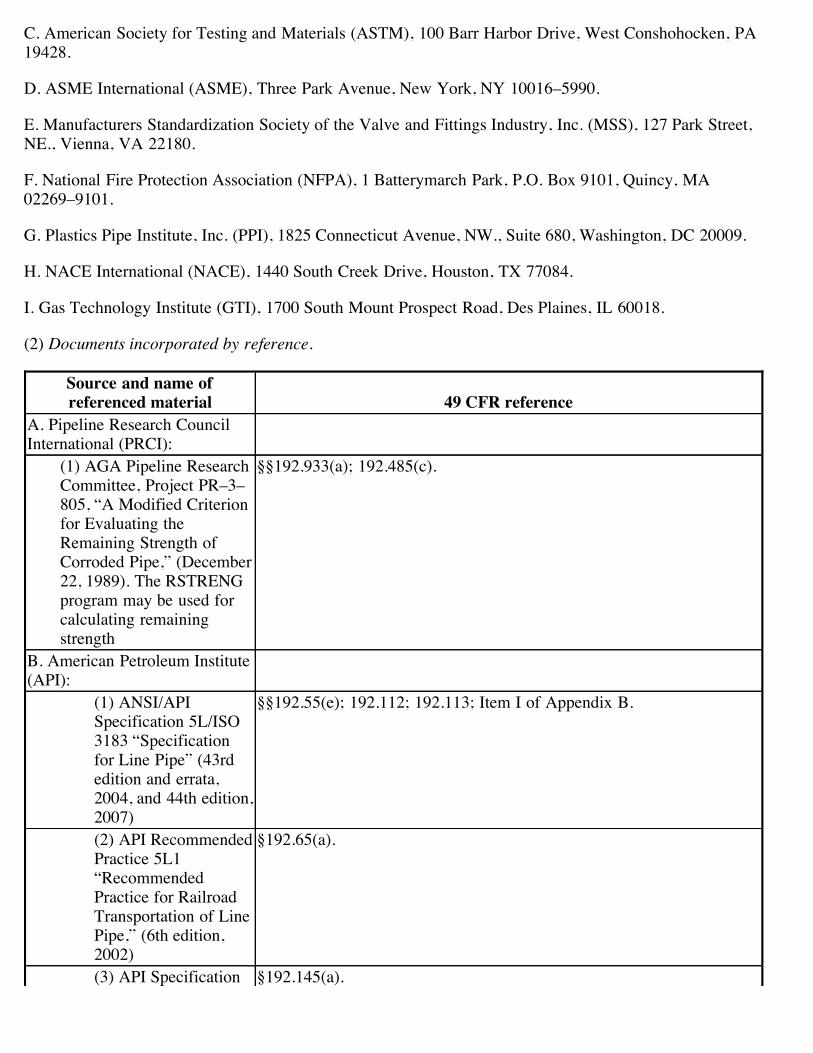
C. American Society for Testing and Materials (ASTM), 100 Barr Harbor Drive, West Conshohocken, PA19428.
D. ASME International (ASME), Three Park Avenue, New York, NY 10016–5990.
E. Manufacturers Standardization Society of the Valve and Fittings Industry, Inc. (MSS), 127 Park Street,NE., Vienna, VA 22180.
F. National Fire Protection Association (NFPA), 1 Batterymarch Park, P.O. Box 9101, Quincy, MA02269–9101.
G. Plastics Pipe Institute, Inc. (PPI), 1825 Connecticut Avenue, NW., Suite 680, Washington, DC 20009.
H. NACE International (NACE), 1440 South Creek Drive, Houston, TX 77084.
I. Gas Technology Institute (GTI), 1700 South Mount Prospect Road, Des Plaines, IL 60018.
(2) Documents incorporated by reference.
Source and name ofreferenced material 49 CFR reference
A. Pipeline Research CouncilInternational (PRCI):
(1) AGA Pipeline ResearchCommittee, Project PR–3–805, “A Modified Criterionfor Evaluating theRemaining Strength ofCorroded Pipe,” (December22, 1989). The RSTRENGprogram may be used forcalculating remainingstrength
§§192.933(a); 192.485(c).
B. American Petroleum Institute(API):
(1) ANSI/APISpecification 5L/ISO3183 “Specificationfor Line Pipe” (43rdedition and errata,2004, and 44th edition,2007)
§§192.55(e); 192.112; 192.113; Item I of Appendix B.
(2) API RecommendedPractice 5L1“RecommendedPractice for RailroadTransportation of LinePipe,” (6th edition,2002)
§192.65(a).
(3) API Specification §192.145(a).
6D “Pipeline Valves,”(22nd edition, January2002)(4) API RecommendedPractice 80,“Guidelines for theDefinition of OnshoreGas Gathering Lines,”(1st edition, April2000)
§192.8(a); 192.8(a)(1); 192.8(a)(2); 192.8(a)(3); 192.8(a)(4).
(5) API 1104“Welding of Pipelinesand Related Facilities”(19th edition 1999,including errataOctober 31, 2001; and20th edition 2007,including errata 2008)
§§192.227(a); 192.229(c)(1); 192.241(c); Item II, and Appendix B.
(6) API RecommendedPractice 1162 “PublicAwareness Programsfor PipelineOperators,” (1stedition, December2003)
§§192.616(a); 192.616(b); 192.616(c).
C. American Society for Testingand Materials (ASTM):
(1) ASTM A53/A53M–04a(2004) “StandardSpecification for Pipe,Steel, Black and Hot-Dipped, Zinc-Coated,Welded and Seamless.”
§§192.113; Item I, Appendix B.
(2) ASTM A106/A106M–04b (2004) “StandardSpecification for SeamlessCarbon Steel Pipe for High-Temperature Service.”
§§192.113; Item I, Appendix B.
(3) ASTM A333/A333M–05 (2005) “StandardSpecification for Seamlessand Welded Steel Pipe forLow-Temperature Service.”
§§192.113; Item I, Appendix B.
(4) ASTM A372/A372M–03 (2003) “StandardSpecification for Carbonand Alloy Steel Forgingsfor Thin-Walled PressureVessels.”
§192.177(b)(1).
(5) ASTM A381–96(Reapproved 2001)“Standard Specification forMetal-Arc Welded SteelPipe for Use With High-Pressure TransmissionSystems.”
§§192.113; Item I, Appendix B.
(6) ASTM Designation: A578/A578M–96 (Re-approved2001) “Standard Specificationfor Straight-Beam UltrasonicExamination of Plain and CladSteel Plates for SpecialApplications”
§§192.112(c)(2)(iii).
(7) ASTM A671–04 (2004)“Standard Specification forElectric-Fusion-WeldedSteel Pipe for Atmosphericand Lower Temperatures.”
§§192.113; Item I, Appendix B.
(8) ASTM A672–96(Reapproved 2001)“Standard Specification forElectric-Fusion-WeldedSteel Pipe for High-Pressure Service atModerate Temperatures.”
§§192.113; Item I, Appendix B.
(9) ASTM A691–98(Reapproved 2002)“Standard Specification forCarbon and Alloy SteelPipe, Electric-Fusion-Welded for High-PressureService at HighTemperatures.”
§§192.113; Item I, Appendix B.
(10) ASTM D638–03“Standard Test Method forTensile Properties ofPlastics.”
§§192.283(a)(3); 192.283(b)(1).
(11) ASTM D2513–87“Standard Specification forThermoplastic Gas PressurePipe, Tubing, and Fittings.”
§192.63(a)(1).
(12) ASTM D2513–99“Standard Specification forThermoplastic Gas PressurePipe, Tubing, and Fittings.”
§§192.191(b); 192.281(b)(2); 192.283(a)(1)(i); Item 1, Appendix B.
(13) ASTM D2517–00“Standard Specification forReinforced Epoxy Resin
§§192.191(a); 192.281(d)(1); 192.283(a)(1)(ii); Item I, Appendix B.
Gas Pressure Pipe andFittings.”(14) ASTM F1055–1998“Standard Specification forElectrofusion TypePolyethylene Fittings forOutside DiameterController PolyethylenePipe and Tubing.”
§192.283(a)(1)(iii).
D. ASME International(ASME):
(1) ASME B16.1–1998“Cast Iron Pipe Flanges andFlanged Fittings.”
§192.147(c).
(2) ASME B16.5–2003(October 2004) “PipeFlanges and FlangedFittings.”
§§192.147(a); 192.279.
(3) ASME B31G–1991(Reaffirmed; 2004)“Manual for Determiningthe Remaining Strength ofCorroded Pipelines.”
§§192.485(c); 192.933(a).
(4) ASME B31.8–2003(February 2004) “GasTransmission andDistribution PipingSystems.”
§192.619(a)(1)(i).
(5) ASME B31.8S–2004“Supplement to B31.8 onManaging System Integrityof Gas Pipelines.”
§§192.903(c); 192.907(b); 192.911, Introductory text; 192.911(i);192.911(k); 192.911(l); 192.911(m); 192.913(a) Introductory text;192.913(b)(1); 192.917(a) Introductory text; 192.917(b); 192.917(c);192.917(e)(1); 192.917(e)(4); 192.921(a)(1); 192.923(b)(2);192.923(b)(3); 192.925(b) Introductory text; 102.925(b)(1);192.925(b)(2); 192.925(b)(3); 192.925(b)(4); 192.927(b);192.927(c)(1)(i); 192.929(b)(1); 192.929(b)(2); 192.933(a);192.933(d)(1); 192.933(d)(1)(i); 192.935(a); 192.935(b)(1)(iv);192.937(c)(1); 192.939(a)(1)(i); 192.939(a)(1)(ii); 192.939(a)(3);192.945(a).
(6) ASME Boiler andPressure Vessel Code,Section I, “Rules forConstruction of PowerBoilers,” (2004 edition,including addenda throughJuly 1, 2005)
§192.153(a).
(7) ASME Boiler andPressure Vessel Code,Section VIII, Division 1,“Rules for Construction of
§§192.153(a); 192.153(b); 192.153(d); 192.165(b)(3).

Pressure Vessels,” (2004edition, including addendathrough July 1, 2005)(8) ASME Boiler andPressure Vessel Code,Section VIII, Division 2,“Rules for Construction ofPressure Vessels—Alternative Rules,” (2004edition, including addendathrough July 1, 2005)
§§192.153(b); 192.165(b)(3).
(9) ASME Boiler andPressure Vessel Code,Section IX, “Welding andBrazing Qualifications,”(2004 edition, includingaddenda through July 1,2005)
§§192.227(a); Item II, Appendix B.
E. ManufacturersStandardization Society of theValve and Fittings Industry, Inc.(MSS):
(1) MSS SP–44–1996(Reaffirmed; 2001) “SteelPipe Line Flanges.”
§192.147(a).
(2) [Reserved]F. National Fire ProtectionAssociation (NFPA):
(1) NFPA 30 (2003)“Flammable andCombustible LiquidsCode.”
§192.735(b).
(2) NFPA 58 (2004)“Liquefied Petroleum GasCode (LP-Gas Code).”
§192.11(a); 192.11(b); 192.11(c).
(3) NFPA 59 (2004)“Utility LP-Gas PlantCode.”
§§192.11(a); 192.11(b); 192.11(c).
(4) NFPA 70 (2005)“National Electrical Code.”
§§192.163(e); 192.189(c).
G. Plastics Pipe Institute, Inc.(PPI):
(1) PPI TR–3/2004 (2004)“Policies and Proceduresfor Developing HydrostaticDesign Basis (HDB),Pressure Design Basis(PDB), Strength Design
§192.121.
Basis (SDB), and MinimumRequired Strength (MRS)Ratings for ThermoplasticPiping Materials or Pipe.”
H. NACE International (NACE):(1) NACE StandardRP0502–2002 “PipelineExternal Corrosion DirectAssessment Methodology.”
§§192.923(b)(1); 192.925(b) Introductory text; 192.925(b)(1);192.925(b)(1)(ii); 192.925(b)(2) Introductory text; 192.925(b)(3)Introductory text; 192.925(b)(3)(ii); 192.925(b)(iv); 192.925(b)(4)Introductory text; 192.925(b)(4)(ii); 192.931(d); 192.935(b)(1)(iv);192.939(a)(2).
I. Gas Technology Institute(GTI):
(1) GRI 02/0057 (2002)“Internal Corrosion DirectAssessment of GasTransmission PipelinesMethodology.”
§192.927(c)(2).
[35 FR 13257, Aug. 19, 1970, as amended by Amdt. 192–37, 46 FR 10159, Feb. 2, 1981; Amdt 192–51, 51FR 15334, Apr. 23, 1986; 58 FR 14521, Mar. 18, 1993; Amdt. 192–78, 61 FR 28783, June 6, 1996; 69 FR18803, Apr. 9, 2004; Amdt. 192–94, 69 FR 32892, June 14, 2004; Amdt. 192–94, 69 FR 54592, Sept. 9,2004; 70 FR 11139, Mar. 8, 2005; Amdt. 192–100, 70 FR 28842, May 19, 2005; Amdt. 192–102, 71 FR13301, Mar. 15, 2006; Amdt. 192–103, 71 FR 33406, June 9, 2006; Amdt. 192–103, 72 FR 4656, Feb. 1,2007; 73 FR 16570, Mar. 28, 2008; 73 FR 62174, Oct. 17, 2008; 74 FR 2894, Jan. 16, 2009; 74 FR 17101,Apr. 14, 2009]
§ 192.8 How are onshore gathering lines and regulated onshore gathering lines determined?
(a) An operator must use API RP 80 (incorporated by reference, see §192.7), to determine if an onshorepipeline (or part of a connected series of pipelines) is an onshore gathering line. The determination issubject to the limitations listed below. After making this determination, an operator must determine if theonshore gathering line is a regulated onshore gathering line under paragraph (b) of this section.
(1) The beginning of gathering, under section 2.2(a)(1) of API RP 80, may not extend beyond thefurthermost downstream point in a production operation as defined in section 2.3 of API RP 80. Thisfurthermost downstream point does not include equipment that can be used in either production ortransportation, such as separators or dehydrators, unless that equipment is involved in the processes of“production and preparation for transportation or delivery of hydrocarbon gas” within the meaning of“production operation.”
(2) The endpoint of gathering, under section 2.2(a)(1)(A) of API RP 80, may not extend beyond the firstdownstream natural gas processing plant, unless the operator can demonstrate, using sound engineeringprinciples, that gathering extends to a further downstream plant.
(3) If the endpoint of gathering, under section 2.2(a)(1)(C) of API RP 80, is determined by thecommingling of gas from separate production fields, the fields may not be more than 50 miles from eachother, unless the Administrator finds a longer separation distance is justified in a particular case (see 49CFR §190.9).
(4) The endpoint of gathering, under section 2.2(a)(1)(D) of API RP 80, may not extend beyond the
furthermost downstream compressor used to increase gathering line pressure for delivery to anotherpipeline.
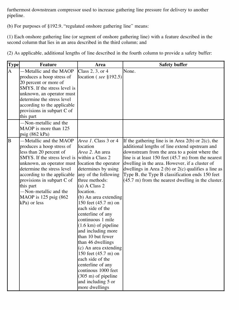
(b) For purposes of §192.9, “regulated onshore gathering line” means:
(1) Each onshore gathering line (or segment of onshore gathering line) with a feature described in thesecond column that lies in an area described in the third column; and
(2) As applicable, additional lengths of line described in the fourth column to provide a safety buffer:
Type Feature Area Safety bufferA —Metallic and the MAOP
produces a hoop stress of20 percent or more ofSMYS. If the stress level isunknown, an operator mustdetermine the stress levelaccording to the applicableprovisions in subpart C ofthis part
Class 2, 3, or 4location ( see §192.5)
None.
—Non-metallic and theMAOP is more than 125psig (862 kPa)
B —Metallic and the MAOPproduces a hoop stress ofless than 20 percent ofSMYS. If the stress level isunknown, an operator mustdetermine the stress levelaccording to the applicableprovisions in subpart C ofthis part—Non-metallic and theMAOP is 125 psig (862kPa) or less
Area 1. Class 3 or 4locationArea 2. An areawithin a Class 2location the operatordetermines by usingany of the followingthree methods:(a) A Class 2location.(b) An area extending150 feet (45.7 m) oneach side of thecenterline of anycontinuous 1 mile(1.6 km) of pipelineand including morethan 10 but fewerthan 46 dwellings(c) An area extending150 feet (45.7 m) oneach side of thecenterline of anycontinous 1000 feet(305 m) of pipelineand including 5 ormore dwellings
If the gathering line is in Area 2(b) or 2(c), theadditional lengths of line extend upstream anddownstream from the area to a point where theline is at least 150 feet (45.7 m) from the nearestdwelling in the area. However, if a cluster ofdwellings in Area 2 (b) or 2(c) qualifies a line asType B, the Type B classification ends 150 feet(45.7 m) from the nearest dwelling in the cluster.

[Amdt. 192–102, 71 FR 13302, Mar. 15, 2006]
§ 192.9 What requirements apply to gathering lines?
(a) Requirements. An operator of a gathering line must follow the safety requirements of this part asprescribed by this section.
(b) Offshore lines. An operator of an offshore gathering line must comply with requirements of this partapplicable to transmission lines, except the requirements in §192.150 and in subpart O of this part.
(c) Type A lines. An operator of a Type A regulated onshore gathering line must comply with therequirements of this part applicable to transmission lines, except the requirements in §192.150 and insubpart O of this part. However, an operator of a Type A regulated onshore gathering line in a Class 2location may demonstrate compliance with subpart N by describing the processes it uses to determine thequalification of persons performing operations and maintenance tasks.
(d) Type B lines. An operator of a Type B regulated onshore gathering line must comply with thefollowing requirements:
(1) If a line is new, replaced, relocated, or otherwise changed, the design, installation, construction, initialinspection, and initial testing must be in accordance with requirements of this part applicable totransmission lines;
(2) If the pipeline is metallic, control corrosion according to requirements of subpart I of this partapplicable to transmission lines;
(3) Carry out a damage prevention program under §192.614;
(4) Establish a public education program under §192.616;
(5) Establish the MAOP of the line under §192.619; and
(6) Install and maintain line markers according to the requirements for transmission lines in §192.707.
(e) Compliance deadlines. An operator of a regulated onshore gathering line must comply with thefollowing deadlines, as applicable.
(1) An operator of a new, replaced, relocated, or otherwise changed line must be in compliance with theapplicable requirements of this section by the date the line goes into service, unless an exception in§192.13 applies.
(2) If a regulated onshore gathering line existing on April 14, 2006 was not previously subject to this part,an operator has until the date stated in the second column to comply with the applicable requirement forthe line listed in the first column, unless the Administrator finds a later deadline is justified in a particularcase:
RequirementCompliance
deadlineControl corrosion according to Subpart I requirements for transmission lines April 15, 2009.Carry out a damage prevention program under §192.614 October 15, 2007.Establish MAOP under §192.619 October 15, 2007.
Install and maintain line markers under §192.707 April 15, 2008.Establish a public education program under §192.616 April 15, 2008.Other provisions of this part as required by paragraph (c) of this section for Type Alines
April 15, 2009.
(3) If, after April 14, 2006, a change in class location or increase in dwelling density causes an onshoregathering line to be a regulated onshore gathering line, the operator has 1 year for Type B lines and 2 yearsfor Type A lines after the line becomes a regulated onshore gathering line to comply with this section.
[Amdt. 192–102, 71 FR 13301, Mar. 15, 2006]
§ 192.10 Outer continental shelf pipelines.
Operators of transportation pipelines on the Outer Continental Shelf (as defined in the Outer ContinentalShelf Lands Act; 43 U.S.C. 1331) must identify on all their respective pipelines the specific points atwhich operating responsibility transfers to a producing operator. For those instances in which the transferpoints are not identifiable by a durable marking, each operator will have until September 15, 1998 toidentify the transfer points. If it is not practicable to durably mark a transfer point and the transfer point islocated above water, the operator must depict the transfer point on a schematic located near the transferpoint. If a transfer point is located subsea, then the operator must identify the transfer point on a schematicwhich must be maintained at the nearest upstream facility and provided to PHMSA upon request. Forthose cases in which adjoining operators have not agreed on a transfer point by September 15, 1998 theRegional Director and the MMS Regional Supervisor will make a joint determination of the transfer point.
[Amdt. 192–81, 62 FR 61695, Nov. 19, 1997, as amended at 70 FR 11139, Mar. 8, 2005]
§ 192.11 Petroleum gas systems.
(a) Each plant that supplies petroleum gas by pipeline to a natural gas distribution system must meet therequirements of this part and ANSI/NFPA 58 and 59.
(b) Each pipeline system subject to this part that transports only petroleum gas or petroleum gas/airmixtures must meet the requirements of this part and of ANSI/NFPA 58 and 59.
(c) In the event of a conflict between this part and ANSI/NFPA 58 and 59, ANSI/NFPA 58 and 59 prevail.
[Amdt. 192–78, 61 FR 28783, June 6, 1996]
§ 192.13 What general requirements apply to pipelines regulated under this part?
(a) No person may operate a segment of pipeline listed in the first column that is readied for service afterthe date in the second column, unless:
(1) The pipeline has been designed, installed, constructed, initially inspected, and initially tested inaccordance with this part; or
(2) The pipeline qualifies for use under this part according to the requirements in §192.14.
Pipeline DateOffshore gathering line July 31, 1977.
Regulated onshore gathering line to which this part did not apply until April 14, 2006 March 15 2007.All other pipelines March 12, 1971.
(b) No person may operate a segment of pipeline listed in the first column that is replaced, relocated, orotherwise changed after the date in the second column, unless the replacement, relocation or change hasbeen made according to the requirements in this part.
Pipeline DateOffshore gathering line July 31, 1977.Regulated onshore gathering line to which this part did not apply until April 14, 2006 March 15, 2007.All other pipelines November 12, 1970.
(c) Each operator shall maintain, modify as appropriate, and follow the plans, procedures, and programsthat it is required to establish under this part.
[35 FR 13257, Aug. 19, 1970, as amended by Amdt. 192–27, 41 FR 34605, Aug. 16, 1976; Amdt. 192–30,42 FR 60148, Nov. 25, 1977; Amdt. 192–102, 71 FR 13303, Mar. 15, 2006]
§ 192.14 Conversion to service subject to this part.
(a) A steel pipeline previously used in service not subject to this part qualifies for use under this part if theoperator prepares and follows a written procedure to carry out the following requirements:
(1) The design, construction, operation, and maintenance history of the pipeline must be reviewed and,where sufficient historical records are not available, appropriate tests must be performed to determine ifthe pipeline is in a satisfactory condition for safe operation.
(2) The pipeline right-of-way, all aboveground segments of the pipeline, and appropriately selectedunderground segments must be visually inspected for physical defects and operating conditions whichreasonably could be expected to impair the strength or tightness of the pipeline.
(3) All known unsafe defects and conditions must be corrected in accordance with this part.
(4) The pipeline must be tested in accordance with subpart J of this part to substantiate the maximumallowable operating pressure permitted by subpart L of this part.
(b) Each operator must keep for the life of the pipeline a record of the investigations, tests, repairs,replacements, and alterations made under the requirements of paragraph (a) of this section.
[Amdt. 192–30, 42 FR 60148, Nov. 25, 1977]
§ 192.15 Rules of regulatory construction.
(a) As used in this part:
Includes means including but not limited to.
May means “is permitted to” or “is authorized to”.
May not means “is not permitted to” or “is not authorized to”.

Shall is used in the mandatory and imperative sense.
(b) In this part:
(1) Words importing the singular include the plural;
(2) Words importing the plural include the singular; and
(3) Words importing the masculine gender include the feminine.
§ 192.16 Customer notification.
(a) This section applies to each operator of a service line who does not maintain the customer's buriedpiping up to entry of the first building downstream, or, if the customer's buried piping does not enter abuilding, up to the principal gas utilization equipment or the first fence (or wall) that surrounds thatequipment. For the purpose of this section, “customer's buried piping” does not include branch lines thatserve yard lanterns, pool heaters, or other types of secondary equipment. Also, “maintain” means monitorfor corrosion according to §192.465 if the customer's buried piping is metallic, survey for leaks accordingto §192.723, and if an unsafe condition is found, shut off the flow of gas, advise the customer of the needto repair the unsafe condition, or repair the unsafe condition.
(b) Each operator shall notify each customer once in writing of the following information:
(1) The operator does not maintain the customer's buried piping.
(2) If the customer's buried piping is not maintained, it may be subject to the potential hazards of corrosionand leakage.
(3) Buried gas piping should be—
(i) Periodically inspected for leaks;
(ii) Periodically inspected for corrosion if the piping is metallic; and
(iii) Repaired if any unsafe condition is discovered.
(4) When excavating near buried gas piping, the piping should be located in advance, and the excavationdone by hand.
(5) The operator (if applicable), plumbing contractors, and heating contractors can assist in locating,inspecting, and repairing the customer's buried piping.
(c) Each operator shall notify each customer not later than August 14, 1996, or 90 days after the customerfirst receives gas at a particular location, whichever is later. However, operators of master meter systemsmay continuously post a general notice in a prominent location frequented by customers.
(d) Each operator must make the following records available for inspection by the Administrator or a Stateagency participating under 49 U.S.C. 60105 or 60106:
(1) A copy of the notice currently in use; and
(2) Evidence that notices have been sent to customers within the previous 3 years.

[Amdt. 192–74, 60 FR 41828, Aug. 14, 1995, as amended by Amdt. 192–74A, 60 FR 63451, Dec. 11,1995; Amdt. 192–83, 63 FR 7723, Feb. 17, 1998]
Browse Next
For questions or comments regarding e-CFR editorial content, features, or design, email [email protected].
For questions concerning e-CFR programming and delivery issues, email [email protected].
Section 508 / Accessibility
APPENDIX F
Wetland and Waterbody Construction and Mitigation Procedures

RUBY PIPELINE PROJECTWETLAND AND WATERBODY CONSTRUCTION AND
MITIGATION PROCEDURES
January 2009

1
RUBY PIPELINE PROJECTWETLAND AND WATERBODY CONSTRUCTION AND
MITIGATION PROCEDURES (PROCEDURES)TABLE OF CONTENTS
I. APPLICABILITY..................................................................................................................... 1
II. PRECONSTRUCTION FILING.............................................................................................. 1
III. ENVIRONMENTAL INSPECTORS ....................................................................................... 2
IV. PRECONSTRUCTION PLANNING....................................................................................... 2
V. WATERBODY CROSSING ................................................................................................... 3
A. NOTIFICATION PROCEDURES AND PERMITS........................................................... 3
B. INSTALLATION ............................................................................................................... 3
1. Time Window for Construction .................................................................................. 4
2. Extra Work Spaces .................................................................................................... 4
4. Spoil Pile Placement and Control .............................................................................. 4
5. Equipment Bridges..................................................................................................... 4
6. Dry-Ditch Crossing Methods ...................................................................................... 5
7. Crossings of Minor Waterbodies ............................................................................... 6
8. Crossings of Intermediate Waterbodies .................................................................... 6
9. Crossings of Major Waterbodies ............................................................................... 7
10. Temporary Erosion and Sediment Control ................................................................ 7
11. Trench Dewatering..................................................................................................... 7
C. RESTORATION ............................................................................................................... 7
D. POST-CONSTRUCTION MAINTENANCE ..................................................................... 8
VI. WETLAND CROSSINGS ...................................................................................................... 8
A. GENERAL ........................................................................................................................ 8
B. INSTALLATION ............................................................................................................... 9
1. Extra Work Areas and Access Roads ................................................................. 9
2. Crossing Procedures ........................................................................................... 9
3. Temporary Sediment Control...............................................................................10
4. Trench Dewatering...............................................................................................10
C. RESTORATION ...............................................................................................................10
D. POST-CONSTRUCTION MAINTENANCE .....................................................................11
VII. HYDROSTATIC TESTING ....................................................................................................12
A. NOTIFICATION................................................................................................................12
B. GENERAL ........................................................................................................................12
C. INTAKE SOURCE AND RAGE........................................................................................13
D. DISCHARGE LOCATION, METHOD, AND RATE..........................................................13
Ruby Pipeline Project Wetland and Waterbody Construction and Mitigation Procedures
1
I. APPLICABILITY
A. The intent of these Procedures is to assist applicants by identifying baseline mitigationmeasures for minimizing the extent and duration of project-related disturbance onwetlands and waterbodies.
Any individual measures in these Procedures Ruby Pipeline LLC (Ruby) considersunnecessary, technically infeasible, or unsuitable due to local conditions will bespecified in this document which will be attached as an appendix to ResourceReport No. 1 filed with the FERC Certificate. Ruby will describe any alternativemeasures proposed for implementation during the construction of its RubyPipeline Project (Project). Applicants should also explain how those alternativemeasures would achieve a comparable level of mitigation. This text will be bold-faced and italicized herein.
Once a project is certificated, further changes can be approved. Any such changes fromthe measures in these Procedures (or the applicant’s approved procedures) will beapproved by the Director of the Office of Energy Projects (Director), upon the applicant’swritten request, if the Director agrees that an alternative measure:
1. provides equal or better environmental protection;
2. is necessary because a portion of these Procedures is infeasible or unworkablebased on project-specific conditions; or
3. is specifically required in writing by another Federal, state, or Native Americanland management agency for the portion of the project on its land or under itsjurisdiction.
Project-related impacts on non-wetland areas are addressed in the Ruby’s UplandErosion Control, Revegetation, and Maintenance Plan (Plan).
B. DEFINITIONS
1. "Waterbody" includes any natural or artificial stream, river, or drainage withperceptible flow at the time of crossing, and other permanent waterbodies suchas ponds and lakes:
a. "minor waterbody" includes all waterbodies less than or equal to 10 feetwide at the water's edge at the time of crossing;
b. "intermediate waterbody" includes all waterbodies greater than 10 feetwide but less than or equal to 100 feet wide at the water's edge at the timeof crossing; and
c. "major waterbody" includes all waterbodies greater than 100 feet wide atthe water's edge at the time of crossing.
2. "Wetland" includes any area that is not in actively cultivated or rotated croplandand that satisfies the requirements of the current Federal methodology foridentifying and delineating wetlands.

Ruby Pipeline Project Wetland and Waterbody Construction and Mitigation Procedures
2
II. PRECONSTRUCTION FILING
A. The following information shall be filed with the Secretary prior to the beginning ofconstruction:
1. the hydrostatic testing information specified in section VII.B.3. and a wetlanddelineation report as described in section VI.A.1., if applicable; and
2. a schedule identifying when trenching or blasting would occur within eachwaterbody greater than 10 feet wide, or within any designated coldwater fishery.The project sponsor shall revise the schedule as necessary to provide FERC staffat least 14 days advance notice. Changes within this last 14-day period mustprovide for at least 48 hours advance notice.
B. The following site-specific construction plans required by these Procedures must be filedwith the Secretary for the review and written approval by the Director:
1. plans for extra work areas that would be closer than 50 feet from a waterbody orwetland;
2. plans for major waterbody crossings;
3. plans for the use of a construction right-of-way greater than 75 feet wide inwetlands; and
4. plans for horizontal directional drill (HDD) "crossings" of wetlands or waterbodies.
III. ENVIRONMENTAL INSPECTORS
A. At least one Environmental Inspector having knowledge of the wetland and waterbodyconditions in the project area is required for each construction spread. The number andexperience of Environmental Inspectors assigned to each construction spread should beappropriate for the length of the construction spread and the number/significance ofresources affected.
B. The Environmental Inspector's responsibilities are outlined in the Upland Erosion Control,Revegetation, and Maintenance Plan (Plan).
IV. PRECONSTRUCTION PLANNING
A. A copy of the Stormwater Pollution Prevention Plan (SWPPP) prepared for compliancewith the U.S. Environmental Protection Agency's (EPA) National Stormwater ProgramGeneral Permit requirements must be available in the field on each construction spread.The SWPPP shall contain Spill Prevention and Response Procedures that meet therequirements of state and Federal agencies.
1. It shall be the responsibility of the project sponsor and its contractors to structuretheir operations in a manner that reduces the risk of spills or the accidentalexposure of fuels or hazardous materials to waterbodies or wetlands. The projectsponsor and its contractors must, at a minimum, ensure that:
a. all employees handling fuels and other hazardous materials are properlytrained;

Ruby Pipeline Project Wetland and Waterbody Construction and Mitigation Procedures
3
b. all equipment is in good operating order and inspected on a regular basis;
c. fuel trucks transporting fuel to on-site equipment travel only on approvedaccess roads;
d. all equipment is parked overnight and/or fueled at least 100 feet from awaterbody or in an upland area at least 100 feet from a wetland boundary.These activities can occur closer only if the Environmental Inspectorfinds, in advance, no reasonable alternative and the project sponsor andits contractors have taken appropriate steps (including secondarycontainment structures) to prevent spills and provide for prompt cleanup inthe event of a spill;
e. hazardous materials, including chemicals, fuels, and lubricating oils, arenot stored within 100 feet of a wetland, waterbody, or designatedmunicipal watershed area, unless the location is designated for such useby an appropriate governmental authority. This applies to storage ofthese materials and does not apply to normal operation or use ofequipment in these areas; and
f. concrete coating activities are not performed within 100 feet of a wetlandor waterbody boundary, unless the location is an existing industrial sitedesignated for such use.
2. The project sponsor and its contractors must structure their operations in amanner that provides for the prompt and effective cleanup of spills of fuel andother hazardous materials. At a minimum, the project sponsor and its contractorsmust:
a. ensure that each construction crew (including cleanup crews) has on handsufficient supplies of absorbent and barrier materials to allow the rapidcontainment and recovery of spilled materials and knows the procedurefor reporting spills;
b. ensure that each construction crew has on hand sufficient tools andmaterial to stop leaks;
c. know the contact names and telephone numbers for all local, state, andFederal agencies (including, if necessary, the U. S. Coast Guard and theNational Response Center) that must be notified of a spill; and
d. follow the requirements of those agencies in cleaning up the spill, inexcavating and disposing of soils or other materials contaminated by aspill, and in collecting and disposing of waste generated during spillcleanup.
Ruby Pipeline Project Wetland and Waterbody Construction and Mitigation Procedures
4
B. AGENCY COORDINATION
The project sponsor must coordinate with the appropriate local, state, and Federalagencies as outlined in these Procedures and in the Certificate.
V. WATERBODY CROSSINGS
A. NOTIFICATION PROCEDURES AND PERMITS
1. Apply to the U.S. Army Corps of Engineers (COE), or its delegated agency, forthe appropriate wetland and waterbody crossing permits.
2. Provide written notification to authorities responsible for potable surface watersupply intakes located within 3 miles downstream of the crossing at least 1 weekbefore beginning work in the waterbody, or as otherwise specified by thatauthority.
3. Apply for state-issued waterbody crossing permits and obtain individual or genericsection 401 water quality certification or waiver.
4. Notify appropriate state authorities at least 48 hours before beginning trenchingor blasting within the waterbody, or as specified in state permits.
B. INSTALLATION
1. Time Window for Construction
Unless expressly permitted or further restricted by the appropriate state agency inwriting on a site-specific basis, instream work, except that required to install orremove equipment bridges, must occur during the following time windows:
a. coldwater fisheries - June 1 through September 30; and
b. coolwater and warmwater fisheries - June 1 through November 30.
2. Extra Work Areas
a. Locate all extra work areas (such as staging areas and additional spoilstorage areas) at least 50 feet away from water’s edge, except where theadjacent upland consists of actively cultivated or rotated cropland or otherdisturbed land.
Temporary workspace would be located 50 feet back from wetlandsand streams unless as site-specific drawing has been approved byFERC and appropriate agencies showing less distance.
b. The project sponsor shall file with the Secretary for review and writtenapproval by the Director, a site-specific construction plan for each extrawork area with a less than 50-foot setback from the water's edge, (exceptwhere the adjacent upland consists of actively cultivated or rotatedcropland or other disturbed land) and a site-specific explanation of theconditions that will not permit a 50-foot setback.

Ruby Pipeline Project Wetland and Waterbody Construction and Mitigation Procedures
5
c. Limit clearing of vegetation between extra work areas and the edge of thewaterbody to the certificated construction right-of-way.
d. Limit the size of extra work areas to the minimum needed to construct thewaterbody crossing.
3. General Crossing Procedures
For streams flowing at the time of crossing and containing sensitive
fish species, Ruby would implement alternate dry crossing techniques
(dam and pump, flumed, partial diversion, or HDD), unless a site-
specific drawing and method is approved by FERC and appropriate
agencies.
For major waterbody crossings (>100 feet), Ruby would adhere to FERC
requirements, unless a site-specific drawing and method is approved
by FERC and appropriate agencies.
a. Comply with the COE, or its delegated agency, permit terms andconditions.
b. Construct crossings as close to perpendicular to the axis of the waterbodychannel as engineering and routing conditions permit.
c. If the pipeline parallels a waterbody, attempt to maintain at least 15 feet ofundisturbed vegetation between the waterbody (and any adjacentwetland) and the construction right-of-way.
d. Where waterbodies meander or have multiple channels, route the pipelineto minimize the number of waterbody crossings.
e. Maintain adequate flow rates to protect aquatic life, and prevent theinterruption of existing downstream uses.
f. Waterbody buffers (extra work area setbacks, refueling restrictions, etc.)must be clearly marked in the field with signs and/or highly visible flagginguntil construction-related ground disturbing activities are complete.
4. Spoil Pile Placement and Control
a. All spoil from minor and intermediate waterbody crossings, and uplandspoil from major waterbody crossings, must be placed in the constructionright-of-way at least 10 feet from the water's edge or in additional extrawork areas as described in section V.B.2.
b. Use sediment barriers to prevent the flow of spoil or heavily silt-ladenwater into any waterbody.
5. Equipment Bridges

Ruby Pipeline Project Wetland and Waterbody Construction and Mitigation Procedures
6
a. Only clearing equipment and equipment necessary for installation ofequipment bridges may cross waterbodies prior to bridge installation.Limit the number of such crossings of each waterbody to one per piece ofclearing equipment.
b. Construct equipment bridges to maintain unrestricted flow and to preventsoil from entering the waterbody. Examples of such bridges include:
(1) equipment pads and culvert(s);(2) equipment pads or railroad car bridges without culverts;(3) clean rock fill and culvert(s); and(4) flexi-float or portable bridges.
Additional options for equipment bridges may be utilized that achieve theperformance objectives noted above. Do not use soil to construct orstabilize equipment bridges.
Design and maintain each equipment bridge to withstand and pass thehighest flow expected to occur while the bridge is in place. Align culvertsto prevent bank erosion or streambed scour. If necessary, install energydissipating devices downstream of the culverts.
Design and maintain equipment bridges to prevent soil from entering thewaterbody.
Remove equipment bridges as soon as possible after permanent seedingunless the COE, or its delegated agency, authorizes it as a permanentbridge.
If there will be more than 1 month between final cleanup and thebeginning of permanent seeding and reasonable alternative access to theright-of-way is available, remove equipment bridges as soon as possibleafter final cleanup.
6. Dry-Ditch Crossing Methods
a. Unless approved otherwise by the appropriate state agency, install thepipeline using one of the dry-ditch methods outlined below for crossings ofwaterbodies up to 30 feet wide (at the water's edge at the time ofconstruction) that are state-designated as either coldwater or significantcoolwater or warmwater fisheries.
b. Dam and Pump
(1) The dam-and-pump method may be used without prior approvalfor crossings of waterbodies where pumps can adequately transferstreamflow volumes around the work area, and there are noconcerns about sensitive species passage.
(2) Implementation of the dam-and-pump crossing method must meetthe following performance criteria:

Ruby Pipeline Project Wetland and Waterbody Construction and Mitigation Procedures
7
(i) use sufficient pumps, including on-site backup pumps, tomaintain downstream flows;
(ii) construct dams with materials that prevent sediment andother pollutants from entering the waterbody (e.g.,sandbags or clean gravel with plastic liner);
(iii) screen pump intakes;(iv) prevent streambed scour at pump discharge; and(v) monitor the dam and pumps to ensure proper operation
throughout the waterbody crossing.
Ruby Pipeline Project Wetland and Waterbody Construction and Mitigation Procedures
8
c. Flume Crossing
The flume crossing method requires implementation of the followingsteps:
(1) install flume pipe after blasting (if necessary), but before anytrenching;
(2) use sand bag or sand bag and plastic sheeting diversion structureor equivalent to develop an effective seal and to divert stream flowthrough the flume pipe (some modifications to the stream bottommay be required in to achieve an effective seal);
(3) properly align flume pipe(s) to prevent bank erosion andstreambed scour;
(4) do not remove flume pipe during trenching, pipelaying, orbackfilling activities, or initial streambed restoration efforts; and
(5) remove all flume pipes and dams that are not also part of theequipment bridge as soon as final cleanup of the stream bed andbank is complete.
d. Horizontal Directional Drill (HDD)
To the extent they were not provided as part of the pre-certificationprocess, for each waterbody or wetland that would be crossed using theHDD method, provide a plan that includes:
(1) site-specific construction diagrams that show the location of mudpits, pipe assembly areas, and all areas to be disturbed or clearedfor construction;
(2) a description of how an inadvertent release of drilling mud wouldbe contained and cleaned up; and
(3) a contingency plan for crossing the waterbody or wetland in theevent the directional drill is unsuccessful and how the abandoneddrill hole would be sealed, if necessary.
7. Crossings of Minor Waterbodies
Where a dry-ditch crossing is not required, minor waterbodies may be crossedusing the open-cut crossing method, with the following restrictions:
a. except for blasting and other rock breaking measures, complete instreamconstruction activities (including trenching, pipe installation, backfill, andrestoration of the streambed contours) within 24 hours. Streambanks andunconsolidated streambeds may require additional restoration after thisperiod;
b. limit use of equipment operating in the waterbody to that needed toconstruct the crossing; and
Ruby Pipeline Project Wetland and Waterbody Construction and Mitigation Procedures
9
c. equipment bridges are not required at minor waterbodies that do not havea state-designated fishery classification (e.g., agricultural or intermittentdrainage ditches). However, if an equipment bridge is used it must beconstructed as described in section V.B.5.
8. Crossings of Intermediate Waterbodies
Where a dry-ditch crossing is not required, intermediate waterbodies may becrossed using the open-cut crossing method, with the following restrictions:
a. complete instream construction activities (not including blasting and otherrock breaking measures) within 48 hours, unless site-specific conditionsmake completion within 48 hours infeasible;
b. limit use of equipment operating in the waterbody to that needed toconstruct the crossing; and
c. all other construction equipment must cross on an equipment bridge asspecified in section V.B.5.
9. Crossings of Major Waterbodies
Before construction, the project sponsor shall file with the Secretary for the reviewand written approval by the Director a detailed, site-specific construction plan andscaled drawings identifying all areas to be disturbed by construction for eachmajor waterbody crossing (the scaled drawings are not required for any offshoreportions of pipeline projects). This plan should be developed in consultation withthe appropriate state and Federal agencies and should include extra work areas,spoil storage areas, sediment control structures, etc., as well as mitigation fornavigational issues.
The Environmental Inspector may adjust the final placement of the erosion andsediment control structures in the field to maximize effectiveness.
10. Temporary Erosion and Sediment Control
Install sediment barriers (as defined in section IV.F.2.a. of the Plan) immediatelyafter initial disturbance of the waterbody or adjacent upland. Sediment barriersmust be properly maintained throughout construction and reinstalled asnecessary (such as after backfilling of the trench) until replaced by permanenterosion controls or restoration of adjacent upland areas is complete. Temporaryerosion and sediment control measures are addressed in more detail in the Plan;however, the following specific measures must be implemented at streamcrossings:
a. install sediment barriers across the entire construction right-of-way at allwaterbody crossings, where necessary to prevent the flow of sedimentsinto the waterbody. In the travel lane, these may consist of removablesediment barriers or driveable berms. Removable sediment barriers canbe removed during the construction day, but must be re-installed afterconstruction has stopped for the day and/or when heavy precipitation isimminent;
Ruby Pipeline Project Wetland and Waterbody Construction and Mitigation Procedures
10
b. where waterbodies are adjacent to the construction right-of-way, installsediment barriers along the edge of the construction right-of-way asnecessary to contain spoil and sediment within the construction right-of-way; and
c. use trench plugs at all waterbody crossings, as necessary, to preventdiversion of water into upland portions of the pipeline trench and to keepany accumulated trench water out of the waterbody.
11. Trench Dewatering
Dewater the trench (either on or off the construction right-of-way) in a manner thatdoes not cause erosion and does not result in heavily silt-laden water flowing intoany waterbody. Remove the dewatering structures as soon as possible after thecompletion of dewatering activities.
C. RESTORATION
1. Use clean gravel or native cobbles for the upper 1 foot of trench backfill in allwaterbodies that contain coldwater fisheries.
2. For open-cut crossings, stabilize waterbody banks and install temporary sedimentbarriers within 24 hours of completing instream construction activities. For dry-ditch crossings, complete streambed and bank stabilization before returning flowto the waterbody channel.
3. Return all waterbody banks to preconstruction contours or to a stable angle ofrepose as approved by the Environmental Inspector.
4. Application of riprap for bank stabilization must comply with COE, or its delegatedagency, permit terms and conditions.
5. Unless otherwise specified by state permit, limit the use of riprap to areas whereflow conditions preclude effective vegetative stabilization techniques such asseeding and erosion control fabric.
6. Revegetate disturbed riparian areas with conservation grasses and legumes ornative plant species, preferably woody species.
7. Install a permanent slope breaker across the construction right-of-way at the baseof slopes greater than 5 percent that are less than 50 feet from the waterbody, oras needed to prevent sediment transport into the waterbody. In addition, installsediment barriers as outlined in the Plan.In some areas, with the approval of the Environmental Inspector, an earthen bermmay be suitable as a sediment barrier adjacent to the waterbody.
8. Sections V.C.3. through V.C.6. above also apply to those perennial or intermittentstreams not flowing at the time of construction.
D. POST-CONSTRUCTION MAINTENANCE
1. Limit vegetation maintenance adjacent to waterbodies to allow a riparian strip atleast 25 feet wide, as measured from the waterbody's mean high water mark, topermanently revegetate with native plant species across the entire construction

Ruby Pipeline Project Wetland and Waterbody Construction and Mitigation Procedures
11
right-of-way. However, to facilitate periodic pipeline corrosion/leak surveys, acorridor centered on the pipeline and up to 10 feet wide may be maintained in aherbaceous state. In addition, trees that are located within 15 feet of the pipelinethat are greater than 15 feet in height may be cut and removed from thepermanent right-of-way.
2. Do not use herbicides or pesticides in or within 100 feet of a waterbody except asallowed by the appropriate land management or state agency.
VI. WETLAND CROSSINGS
A. GENERAL
1. The project sponsor shall conduct a wetland delineation using the current Federalmethodology and file a wetland delineation report with the Secretary beforeconstruction. This report shall identify:
a. by milepost all wetlands that would be affected;
b. the National Wetlands Inventory (NWI) classification for each wetland;
c. the crossing length of each wetland in feet; and
d. the area of permanent and temporary disturbance that would occur ineach wetland by NWI classification type.
The requirements outlined in this section do not apply to wetlands in activelycultivated or rotated cropland. Standard upland protective measures, includingworkspace and topsoiling requirements, apply to these agricultural wetlands.
2. Route the pipeline to avoid wetland areas to the maximum extent possible. If awetland cannot be avoided or crossed by following an existing right-of-way, routethe new pipeline in a manner that minimizes disturbance to wetlands. Wherelooping an existing pipeline, overlap the existing pipeline right-of-way with the newconstruction right-of-way. In addition, locate the loop line no more than 25 feetaway from the existing pipeline unless site-specific constraints would adverselyaffect the stability of the existing pipeline.
3. Limit the width of the construction right-of-way to 75 feet or less. Prior writtenapproval of the Director is required where topographic conditions or soillimitations require that the construction right-of-way width within the boundaries ofa federally delineated wetland be expanded beyond 75 feet. Early in the planningprocess the project sponsor is encouraged to identify site-specific areas whereexisting soils lack adequate unconfined compressive strength that would result inexcessively wide ditches and/or difficult to contain spoil piles.
The construction ROW width for all wetland crossings will be limited to 75feet to minimize impacts, unless a site-specific drawing and method isapproved by FERC and appropriate agencies.
Ruby Pipeline Project Wetland and Waterbody Construction and Mitigation Procedures
12
4. Wetland boundaries and buffers must be clearly marked in the field with signsand/or highly visible flagging until construction-related ground disturbing activitiesare complete.
5. Implement the measures of sections V. and VI. in the event a waterbody crossingis located within or adjacent to a wetland crossing. If all measures of sections V.and VI. cannot be met, the project sponsor must file with the Secretary a site-specific crossing plan for review and written approval by the Director beforeconstruction. This crossing plan shall address at a minimum:
a. spoil control;
b. equipment bridges;
c. restoration of waterbody banks and wetland hydrology;
d. timing of the waterbody crossing;
e. method of crossing; and
f. size and location of all extra work areas.
6. Do not locate aboveground facilities in any wetland, except where the location ofsuch facilities outside of wetlands would prohibit compliance with U.S.Department of Transportation regulations.
B. INSTALLATION
1. Extra Work Areas and Access Roads
a. Locate all extra work areas (such as staging areas and additional spoilstorage areas) at least 50 feet away from wetland boundaries, exceptwhere the adjacent upland consists of actively cultivated or rotatedcropland or other disturbed land.
b. The project sponsor shall file with the Secretary for review and writtenapproval by the Director, a site-specific construction plan for each extrawork area with a less than 50-foot setback from wetland boundaries(except where adjacent upland consists of actively cultivated or rotatedcropland or other disturbed land) and a site-specific explanation of theconditions that will not permit a 50-foot setback.
c. Limit clearing of vegetation between extra work areas and the edge of thewetland to the certificated construction right-of-way.
d. The construction right-of-way may be used for access when the wetlandsoil is firm enough to avoid rutting or the construction right-of-way hasbeen appropriately stabilized to avoid rutting (e.g., with timber riprap,prefabricated equipment mats, or terra mats).
In wetlands that cannot be appropriately stabilized, all constructionequipment other than that needed to install the wetland crossing shall useaccess roads located in upland areas. Where access roads in upland
Ruby Pipeline Project Wetland and Waterbody Construction and Mitigation Procedures
13
areas do not provide reasonable access, limit all other constructionequipment to one pass through the wetland using the construction right-of-way.
e. The only access roads, other than the construction right-of-way, that canbe used in wetlands without Director approval, are those existing roadsthat can be used with no modification and no impact on the wetland.
2. Crossing Procedures
a. Comply with COE, or its delegated agency, permit terms and conditions
b. Assemble the pipeline in an upland area unless the wetland is dry enoughto adequately support skids and pipe.
c. Use "push-pull" or "float" techniques to place the pipe in the trench wherewater and other site conditions allow.
d. Minimize the length of time that topsoil is segregated and the trench isopen.
e. Limit construction equipment operating in wetland areas to that needed toclear the construction right-of-way, dig the trench, fabricate and install thepipeline, backfill the trench, and restore the construction right-of-way.
f. Cut vegetation just aboveground level, leaving existing root systems inplace, and remove it from the wetland for disposal.
g. Limit pulling of tree stumps and grading activities to directly over thetrenchline. Do not grade or remove stumps or root systems from the restof the construction right-of-way in wetlands unless the Chief Inspector andEnvironmental Inspector determine that safety-related constructionconstraints require grading or the removal of tree stumps from under theworking side of the construction right-of-way.
h. Segregate the top 1 foot of topsoil from the area disturbed by trenching,except in areas where standing water is present or soils are saturated orfrozen. Immediately after backfilling is complete, restore the segregatedtopsoil to its original location.
i. Do not use rock, soil imported from outside the wetland, tree stumps, orbrush riprap to support equipment on the construction right-of-way.
j. If standing water or saturated soils are present, or if constructionequipment causes ruts or mixing of the topsoil and subsoil in wetlands,use low-ground-weight construction equipment, or operate normalequipment on timber riprap, prefabricated equipment mats, or terra mats.
k. Do not cut trees outside of the approved construction work area to obtaintimber for riprap or equipment mats.
l. Attempt to use no more than two layers of timber riprap to supportequipment on the construction right-of-way.

Ruby Pipeline Project Wetland and Waterbody Construction and Mitigation Procedures
14
m. Remove all project-related material used to support equipment on theconstruction right-of-way upon completion of construction.
3. Temporary Sediment Control
Install sediment barriers (as defined in section IV.F.2.a. of the Plan) immediatelyafter initial disturbance of the wetland or adjacent upland. Sediment barriersmust be properly maintained throughout construction and reinstalled asnecessary (such as after backfilling of the trench). Except as noted below insection VI.B.3.c., maintain sediment barriers until replaced by permanent erosioncontrols or restoration of adjacent upland areas is complete. Temporary erosionand sediment control measures are addressed in more detail in the Plan.
a. Install sediment barriers across the entire construction right-of-way at allwetland crossings where necessary to prevent sediment flow into thewetland. In the travel lane, these may consist of removable sedimentbarriers or driveable berms. Removable sediment barriers can beremoved during the construction day, but must be re-installed afterconstruction has stopped for the day and/or when heavy precipitation isimminent
b. Where wetlands are adjacent to the construction right-of-way and theright-of-way slopes toward the wetland, install sediment barriers along theedge of the construction right-of-way as necessary to prevent sedimentflow into the wetland.
c. Install sediment barriers along the edge of the construction right-of-way asnecessary to contain spoil and sediment within the construction right-of-way through wetlands. Remove these sediment barriers during right-of-way cleanup.
4. Trench Dewatering
Dewater the trench (either on or off the construction right-of-way) in a manner thatdoes not cause erosion and does not result in heavily silt-laden water flowing intoany wetland. Remove the dewatering structures as soon as possible after thecompletion of dewatering activities.
C. RESTORATION
1. Where the pipeline trench may drain a wetland, construct trench breakers and/orseal the trench bottom as necessary to maintain the original wetland hydrology.
2. For each wetland crossed, install a trench breaker at the base of slopes near theboundary between the wetland and adjacent upland areas. Install a permanentslope breaker across the construction right-of-way at the base of a slopes greaterthan 5 percent where the base of the slope is less than 50 feet from the wetland,or as needed to prevent sediment transport into the wetland. In addition, installsediment barriers as outlined in the Plan. In some areas, with the approval of theEnvironmental Inspector, an earthen berm may be suitable as a sediment barrieradjacent to the wetland.
3. Do not use fertilizer, lime, or mulch unless required in writing by the appropriateland management or state agency.

Ruby Pipeline Project Wetland and Waterbody Construction and Mitigation Procedures
15
4. Consult with the appropriate land management or state agency to develop aproject-specific wetland restoration plan. The restoration plan should includemeasures for re-establishing herbaceous and/or woody species, controlling theinvasion and spread of undesirable exotic species (e.g., purple loosestrife andphragmites), and monitoring the success of the revegetation and weed controlefforts. Provide this plan to the FERC staff upon request.
5. Until a project-specific wetland restoration plan is developed and/or implemented,temporarily revegetate the construction right-of-way with annual ryegrass at a rateof 40 pounds/acre (unless standing water is present).
6. Ensure that all disturbed areas successfully revegetate with wetland herbaceousand/or woody plant species.
7. Remove temporary sediment barriers located at the boundary between wetlandand adjacent upland areas after upland revegetation and stabilization of adjacentupland areas are judged to be successful as specified in section VII.A.5. of thePlan.
D. POST-CONSTRUCTION MAINTENANCE
1. Do not conduct vegetation maintenance over the full width of the permanent right-of-way in wetlands. However, to facilitate periodic pipeline corrosion/leaksurveys, a corridor centered on the pipeline and up to 10 feet wide may bemaintained in a herbaceous state. In addition, trees within 15 feet of the pipelinethat are greater than 15 feet in height may be selectively cut and removed fromthe permanent right-of-way.
2. Do not use herbicides or pesticides in or within 100 feet of a wetland, except asallowed by the appropriate land management agency or state agency.
3. Monitor and record the success of wetland revegetation annually for the first 3years after construction or until wetland revegetation is successful. At the end of3 years after construction, file a report with the Secretary identifying the status ofthe wetland revegetation efforts. Include the percent cover achieved and problemareas (weed invasion issues, poor revegetation, etc.). Continue to file a reportannually until wetland revegetation is successful.
4. Wetland revegetation shall be considered successful if the cover of herbaceousand/or woody species is at least 80 percent of the type, density, and distributionof the vegetation in adjacent wetland areas that were not disturbed byconstruction. If revegetation is not successful at the end of 3 years, develop andimplement (in consultation with a professional wetland ecologist) a remedialrevegetation plan to actively revegetate the wetland. Continue revegetationefforts until wetland revegetation is successful.
VII. HYDROSTATIC TESTING
A. NOTIFICATION PROCEDURES AND PERMITS
1. Apply for state-issued water withdrawal permits, as required.

Ruby Pipeline Project Wetland and Waterbody Construction and Mitigation Procedures
16
2. Apply for National Pollutant Discharge Elimination System (NPDES) or state-issued discharge permits, as required.
3. Notify appropriate state agencies of intent to use specific sources at least 48hours before testing activities unless they waive this requirement in writing.
B. GENERAL
1. Perform non-destructive testing of all pipeline section welds or hydrotest thepipeline sections, before installation under waterbodies or wetlands.
2. If pumps used for hydrostatic testing are within 100 feet of any waterbody orwetland, address the operation and refueling of these pumps in the project’s SpillPrevention and Response Procedures.
3. The project sponsor shall file with the Secretary before construction a listidentifying the location of all waterbodies proposed for use as a hydrostatic testwater source or discharge location.
C. INTAKE SOURCE AND RATE
1. Screen the intake hose to prevent entrainment of fish.
2. Do not use state-designated exceptional value waters, waterbodies which providehabitat for federally listed threatened or endangered species, or waterbodiesdesignated as public water supplies, unless appropriate Federal, state, and/orlocal permitting agencies grant written permission.
3. Maintain adequate flow rates to protect aquatic life, provide for all waterbodyuses, and provide for downstream withdrawals of water by existing users.
4. Locate hydrostatic test manifolds outside wetlands and riparian areas to themaximum extent practicable.
D. DISCHARGE LOCATION, METHOD, AND RATE
1. Regulate discharge rate, use energy dissipation device(s), and install sedimentbarriers, as necessary, to prevent erosion, streambed scour, suspension ofsediments, or excessive streamflow.
2. Do not discharge into state-designated exceptional value waters, waterbodieswhich provide habitat for federally listed threatened or endangered species, orwaterbodies designated as public water supplies, unless appropriate Federal,state, and local permitting agencies grant written permission.

FERC FILING VERSION 1/23/09
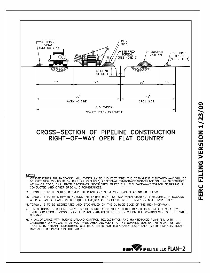
FERC FILING VERSION 1/23/09

FERC FILING VERSION 1/23/09

FERC FILING VERSION 1/23/09
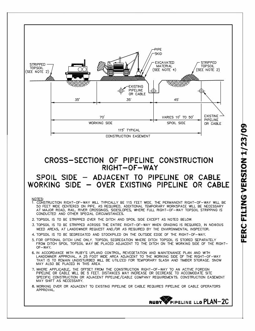
FERC FILING VERSION 1/23/09
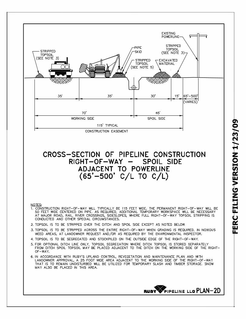
FERC FILING VERSION 1/23/09

FERC FILING VERSION 1/23/09

FERC FILING VERSION 1/23/09

FERC FILING VERSION 1/23/09
12"−18"
28"−30"

FERC FILING VERSION 1/23/09
36" X 2" X 2" MIN. FENCE POSTS OR
APPROVED EQUIVALENT
DRIVEN 12-18" INTO GROUND AS
SITE CONDITIONS ALLOW
WETLAND/
WATERBODY/
HIGHWAY/
RAILROAD
PROPOSED PIPE
SLOPE
HAY/STRAW BALES
HAY/STRAW BALES TIGHTLY
STAKED TOGETHER
BINDINGS SHOULD
BE HORIZONTALHAY/STRAW BALES TO BE EMBEDDED 2" MIN. INTO
GROUND AS SITE CONDITIONS ALLOW.
SECOND WOODEN STAKE
SHOULD BE ANGLED TO
PREVIOUSLY LAID BALE
INSTALL ROCK
CONSTRUCTION
ENTRANCE ATALL PAVED
ROADWAYS,
AS NEEDED.
1.
12-18"2-4"
SEDIMENT SHALL BE REMOVED WHEN ACCUMULATIONS
REACH 1/2 THE ABOVEGROUND HEIGHT OF THE BARRIER.
2.
HAY/STRAW BALES REMOVED FOR ACCESS PURPOSES
DURING THE DAY MUST BE REINSTALLED AFTER THE
CONSTRUCTION ACTIVITY HAS PASSED THROUGH OR BY
THE END OF THE DAY.
3.

FERC FILING VERSION 1/23/09
NOTE
1. CONSTRUCT ON SLOPING TERRAIN AND ADJACENT TO ALL
WATERBODIES AND WETLANDS, AS REQUIRED
(SEE TABLE BELOW).2. PRIOR TO LOWERING IN PIPE REMOVE ALL DECOMPOSABLE
MATERIAL AND LARGE ROCKS.
3. BREAKERS MAY BE COMPOSED OF SANDBAGS OR OTHER APPROVED MATERIAL.
4. MINIMUM 12 INCHES COVER OVER SANDBAGS IN ALL CASES AND MUST BE A MINIMUM OF 2 SACKS WIDE.
5. TOPSOIL SHALL NOT BE USED TO FILL SACKS.
GRADED RIGHT-OF-WAY
SANDBAGS
PIPELINE
BOTTOM
OF DITCH
MIN. 2 SACKS WIDE
FILLRESTORED GRADE
SANDBAGS
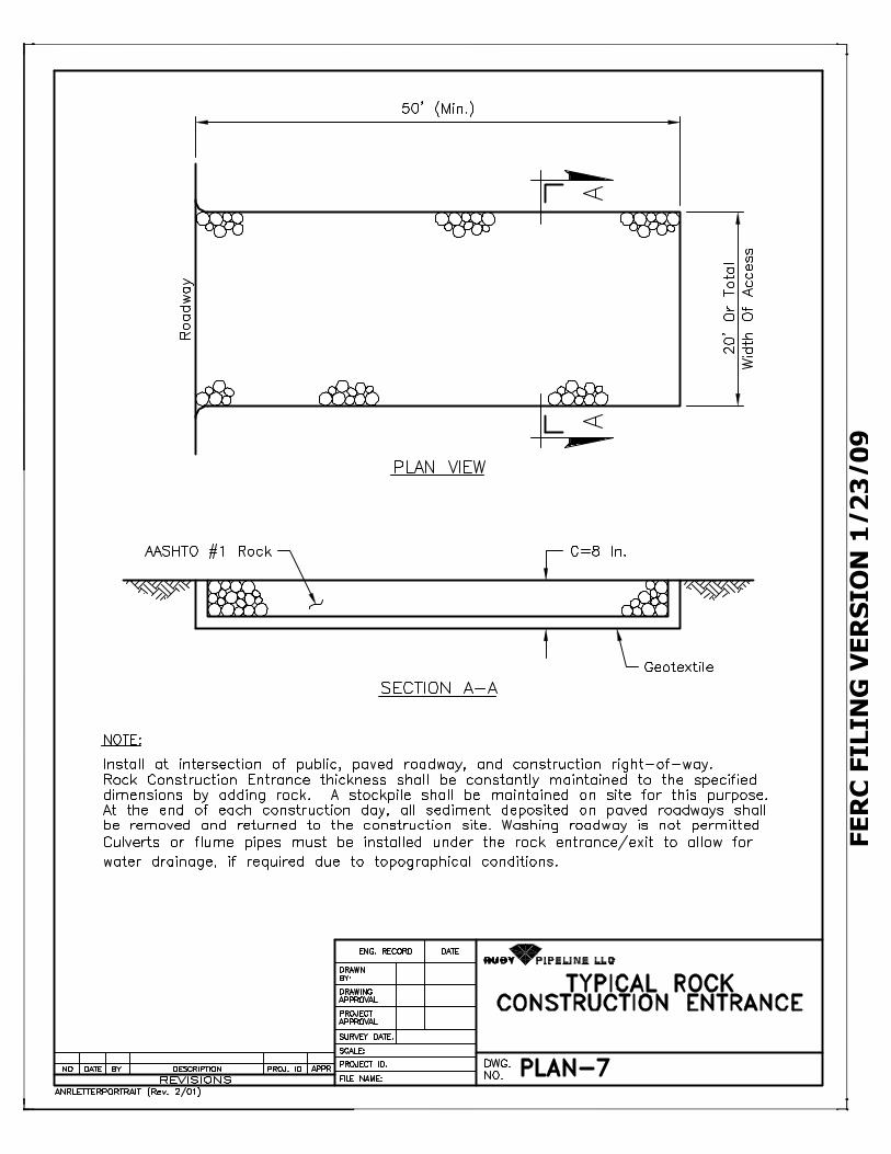
FERC FILING VERSION 1/23/09

FERC FILING VERSION 1/23/09
STABILIZED FILL
JUTE OR EQUAL
EROSION
CONTROL FABRIC
DIVERSION BERM
STRAW
MULCH OR
EQUAL
PERMANENT BANK
STREAM BANK
TYPICALSTREAM
EROSION CONTROL
FABRIC12"
4' 4'
6"
STABILIZED FILL
PROVIDE MINIMUM OF 6" OF SOIL COVER OVER
FIRST 12" OF EROSION CONTROL FABRIC AS
SHOWN.
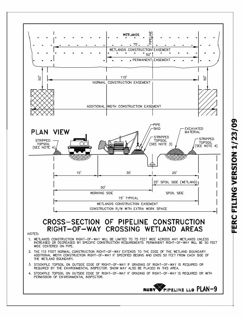
FERC FILING VERSION 1/23/09
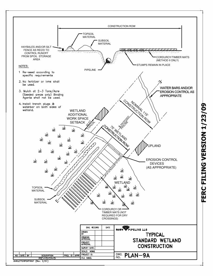
FERC FILING VERSION 1/23/09
EROSION CONTROL
DEVICES
(AS APPROPRIATE)
CONSTRUCTION ROW
TOPSOIL
MATERIAL
SUBSOIL
MATERIAL
HAYBALES AND/OR SILT
FENCE AS REQ'D TO
CONTROL RUNOFF
FROM SPOIL STORAGE
AREACORDUROY/TIMBER MATS
(METHOD II ONLY)
STUMPS REMAIN IN PLACE
WETLAND
ADDITIONAL
WORK SPACE
SETBACK P
RO
PO
SED
PIP
ELI
NE
NO
MIN
AL 115'
CO
NSTR
UCTIO
N ROW
UPLAND
WETLAND
50 F
TTY
PIC
AL
TOPSOIL
MATERIAL
SUBSOIL
MATERIAL
CORDUROY OR
TIMBER MATS (NOT
REQUIRED FOR DRY
CROSSINGS)
PIPELINE
75' WETLAND

FERC FILING VERSION 1/23/09
SPOIL PILE
(10 FT SET BACK
SEE NOTE 3)
SPOIL PILE
(10 FT SET BACKSEE NOTE 3)
EROSION
CONTROL
DEVICES ASAPPROPRIATE
STREAM FLOW
PROPOSED
PIPELINE
CONSTRUCTION ROW
TRENCH
TRENCH
PLUGS
FLUME
PIPE(S)
50
'S
EE
NO
TE
2
EXISTING VEGETATION
MAINTAINED TO MAX.
POSSIBLE WIDTH
TWS
SANDBAGS
TWS
EQUIPMENT
CROSSING
CROSS SECTION FOR EQUIPMENT CROSSING
EROSION
CONTROL
DEVICES ASAPPROPRIATE
EROSION
CONTROL
DEVICES ASAPPROPRIATE
CLEAN STONE OR ROCK
(INSTALL 1' MIN. OF FILL
OVER CULVERT)
FLUME PIPE(S) MIN. SIZE 12"
(SUBMERGED). IF MORE THAN
ONE CULVERT IS USED, THE
MIN. SPACING IS 12".
NOTE:
1. PORTABLE BRIDGES OR MATS MAY BE USED FOR EQUIPMENT CROSSING IF CONTOURS ALLOW.
2. THE REQUIRED SETBACK FOR ADDITIONAL WIDTH WORK SPACE IS 50 FEET FROM TOP OF BANK
UNLESS APPROVED OTHERWISE BY THE APPROPRIATE AGENCIES.
3. THE MINIMUM REQUIRED SETBACK FOR SPOIL PILE IS 10 FEET FROM THE TOP OF BANK.
4. EQUIPMENT BRIDGE TO REMAIN IN PLACE UNTIL THE COMPLETION OF FINAL RESTORATION.
5. WEED-FREE STRAW BALES, SAND BAGS, DRIVABLE BERMS OR OTHER APPROPRIATE EROSION
CONTROL MAY BE USED INTERCHANGEABLY AT THE EDGE OF EQUIPMENT BRIDGE.
12"
12 " MIN. SPACING
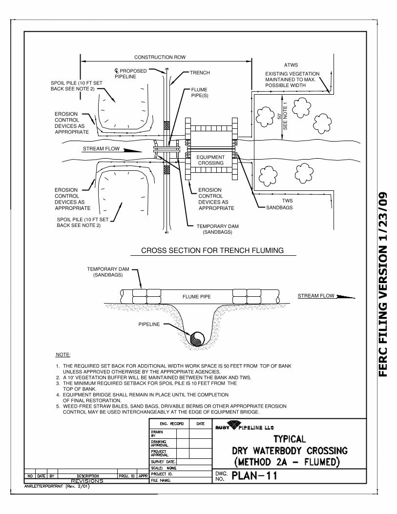
FERC FILING VERSION 1/23/09
SPOIL PILE (10 FT SET
BACK SEE NOTE 2)
EROSION
CONTROL
DEVICES ASAPPROPRIATE
EROSION
CONTROL
DEVICES AS
APPROPRIATE
EROSION
CONTROL
DEVICES AS
APPROPRIATE
SPOIL PILE (10 FT SET
BACK SEE NOTE 2) TEMPORARY DAM(SANDBAGS)
STREAM FLOW
EQUIPMENT
CROSSING
FLUME
PIPE(S)
TRENCH PROPOSEDPIPELINE
CONSTRUCTION ROW
EXISTING VEGETATION
MAINTAINED TO MAX.
POSSIBLE WIDTH
ATWS
SANDBAGS
CROSS SECTION FOR TRENCH FLUMING
FLUME PIPE
PIPELINE
NOTE:
1. THE REQUIRED SET BACK FOR ADDITIONAL WIDTH WORK SPACE IS 50 FEET FROM TOP OF BANK
UNLESS APPROVED OTHERWISE BY THE APPROPRIATE AGENCIES.
2. A 10' VEGETATION BUFFER WILL BE MAINTAINED BETWEEN THE BANK AND TWS.3. THE MINIMUM REQUIRED SETBACK FOR SPOIL PILE IS 10 FEET FROM THE
TOP OF BANK.
4. EQUIPMENT BRIDGE SHALL REMAIN IN PLACE UNTIL THE COMPLETION
OF FINAL RESTORATION.5. WEED-FREE STRAW BALES, SAND BAGS, DRIVABLE BERMS OR OTHER APPROPRIATE EROSION
CONTROL MAY BE USED INTERCHANGEABLY AT THE EDGE OF EQUIPMENT BRIDGE.
TEMPORARY DAM
(SANDBAGS)5
0'
SE
E N
OT
E 1
TWS
STREAM FLOW
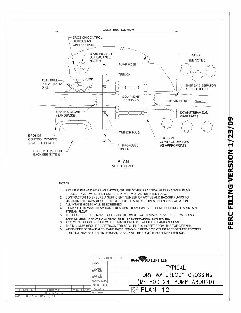
FERC FILING VERSION 1/23/09
NOTES:
1. SET UP PUMP AND HOSE AS SHOWN, OR USE OTHER PRACTICAL ALTERNATIVES. PUMP
SHOULD HAVE TWICE THE PUMPING CAPACITY OF ANTICIPATED FLOW.
2. CONTRACTOR TO ENSURE A SUFFICIENT NUMBER OF ACTIVE AND BACKUP PUMPS TO
MAINTAIN THE CAPACITY OF THE STREAM FLOW AT ALL TIMES DURING INSTALLATION.
3. ALL INTAKE HOSES WILL BE SCREENED.
4. DISMANTLE DOWNSTREAM DAM, THEN UPSTREAM DAM. KEEP PUMP RUNNING TO MAINTAIN
STREAM FLOW.
5. THE REQUIRED SET BACK FOR ADDITIONAL WIDTH WORK SPACE IS 50 FEET FROM TOP OF
BANK UNLESS APPROVED OTHERWISE BY THE APPROPRIATE AGENCIES.
6. A 10' VEGETATION BUFFER WILL BE MAINTAINED BETWEEN THE BANK AND TWS.
7. THE MINIMUM REQUIRED SETBACK FOR SPOIL PILE IS 10 FEET FROM THE TOP OF BANK.
8. WEED-FREE STRAW BALES, SAND BAGS, DRIVABLE BERMS OR OTHER APPROPRIATE EROSION
CONTROL MAY BE USED INTERCHANGEABLY AT THE EDGE OF EQUIPMENT BRIDGE.
EROSION CONTROL
DEVICES AS
APPROPRIATE
EROSION
CONTROL DEVICES
AS APPROPRIATE
EROSION
CONTROL DEVICES
AS APPROPRIATE
SPOIL PILE (10 FT
SET BACK SEENOTE 6)
SPOIL PILE (10 FT SET
BACK SEE NOTE 6)
PUMP HOSE
PUMP
TRENCH
EQUIPMENTCROSSING
UPSTREAM DAM
(SANDBAGS)
TRENCH PLUG
PROPOSEDPIPELINE
DOWNSTREAM DAM
(SANDBAGS)
STREAM FLOW
ENERGY DISSIPATOR
AND/OR FILTER
SEE NOTE 5
ATWS
CONSTRUCTION ROW
PLANNOT TO SCALE
FUEL SPILL
PREVENTATIVEDIKE
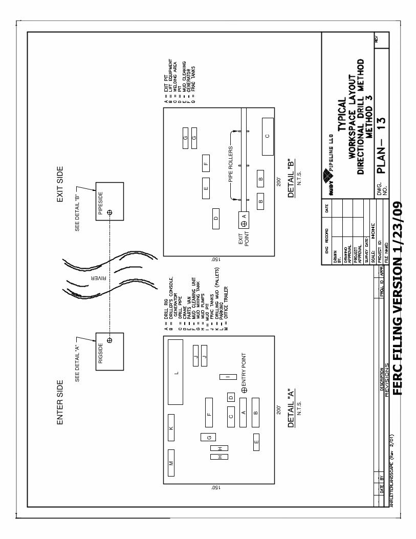
FERC FILING VERSION 1/23/09
EN
TE
R S
IDE
EX
IT S
IDE
SE
E D
ET
AIL
"A
"S
EE
DE
TA
IL "
B"
RIVER
RIG
SID
EP
IPE
SID
E
MK
L
J J
HH
FG
CD
I
A BE
EN
TR
Y P
OIN
T
20
0'
150'
20
0'
150'
N.T
.S.
N.T
.S.
PIP
E R
OLLE
RS
D
EF
A
BB
CGG
EX
IT
PO
INT

FERC FILING VERSION 1/23/09
NOTES
1. THIS TYPE OF BRIDGE IS GENERALLY USED FOR MEDIUM-SIZED STREAM
CROSSINGS.
2. THE NUMBER AND SIZE OF THE FLUME PIPES WILL BE DESIGNED TO
HANDLE MAXIMUM EXPECTED FLOW OF STREAM AT TIME OF
CONSTRUCTION. MIN. SIZE CULVERT WILL BE 12".
3. CLEAN, SILT-FREE ROCK TO BE USED ONLY. INSTALL 1" MIN. OF
FILL OVER CULVERT.
4. BRIDGE TO REMAIN IN PLACE UNTIL THE COMPLETION OF FINAL
RESTORATION.
5. SILT FENCE, WEED-FREE STRAW BALES, SANDBAGS, DRIVABLE BERMS OR
OTHER APPROPRIATE EROSION CONTROL MAY BE USED
INTERCHANGEABLY.
6. STRAW BALES WILL BE PLACED AT THE EDGE OF EQUIPMENT BRIDGE
AT THE END OF THE WORK DAY TO PREVENT EROSION BUT WILL BE
REMOVED DURING CONSTRUCTION ACTIVITY.
EROSION
CONTROL
DEVICE(S)
EROSION
CONTROL
DEVICE(S)
CLEAN, SILT-FREE
(WASHED) STONE
CLEAN, SILT-FREE
(WASHED) STONE
TIMBER MATS
EDGE OF WATER STREAM
TIMBER MATS
12" MIN. SPACING

FERC FILING VERSION 1/23/09
STREAMEDGE OF WATER
TIMBER MATS
HAYBALES
TIMBER MATS
HAYBALES
1. THIS TYPE OF BRIDGE IS GENERALLY USED FOR SMALL STREAM
CROSSINGS LESS THAN 20 FEET IN WIDTH IN COMBINATION WITH
A PROPER STREAM BANK CONFIGURATION.
2. BRIDGE WILL BE TEMPORARILY REMOVED IF HIGH WATER
RENDERS IT UNSAFE FOR CROSSING.
3. BRIDGE TO REMAIN IN PLACE UNTIL THE COMPLETION OF FINAL
RESTORATION.
4. SILT FENCE, WEED FREE STRAW BALES, SAND BAGS, DRIVABLE
BERMS OR OTHER APPROPRIATE EROSION CONTROL MAY BE USED
INTERCHANGEABLY.
5. A "SKIRT" FORMED OF SILT FENCE, GEOTEXTILE FABRIC OR
EQUIVALENT SHALL BE PLACED ON THE SIDES AND BOTTOM
OF THE BRIDGE TO TRAP SEDIMENT AS NECESSARY.
6. INDIVIDUAL MATS SHALL BE ANCHORED AND BUTTED TIGHTLY TO
MINIMIZE THE INTRODUCTION OF SEDIMENT TO THE WATERBODY.
7. STRAW BALES OR APPROPRIATE BARRIER WILL BE PLACED AT
THE EDGE.
SILT FENCE, GEOTEXTILE
OR EQUIVALENT "SKIRT"

FERC FILING VERSION 1/23/09
STREAM
EDGE OF WATER
CLEAN, SILT-FREE
(WASHED) STONE
EROSION
CONTROL
DEVICE(S)
1. THIS TYPE OF BRIDGE IS USED ON MEDIUM TO LARGE STREAMS
WITH POTENTIAL FOR SIGNIFICANT FLOW.
2. THE NUMBER AND SIZE OF FLUME PIPES WILL BE DESIGNED TO
HANDLE THE MAXIMUM EXPECTED FLOW OF THE STREAM AT TIME
OF CONSTRUCTION. MIN. SIZE CULVERT WILL BE 12".
3. CLEAN, SILT-FREE ROCK TO BE USED ONLY. INSTALL 1" MIN. OF
FILL OVER CULVERT.
4. BRIDGE TO REMAIN IN PLACE UNTIL THE COMPLETION OF FINAL
RESTORATION.
5. SILT FENCE, WEED-FREE STRAW BALES, SANDBAGS, DRIVABLE BERMS OR
OTHER APPROPRIATE EROSION CONTROL MAY BE USED
INTERCHANGEABLY.
6. ROCK MUST EXTEND 10' FROM TOP OF BANK ON BOTH SIDES
OF WATERWAY.
7. STRAW BALES WILL BE PLACED AT THE EDGE OF EQUIPMENT
BRIDGE AT THE END OF THE WORK DAY TO PREVENT EROSION
BUT WILL BE REMOVED DURING CONSTRUCTION ACTIVITY.
EROSION
CONTROL
DEVICE(S)
CLEAN, SILT-FREE
(WASHED) STONE
12" MIN. SPACING
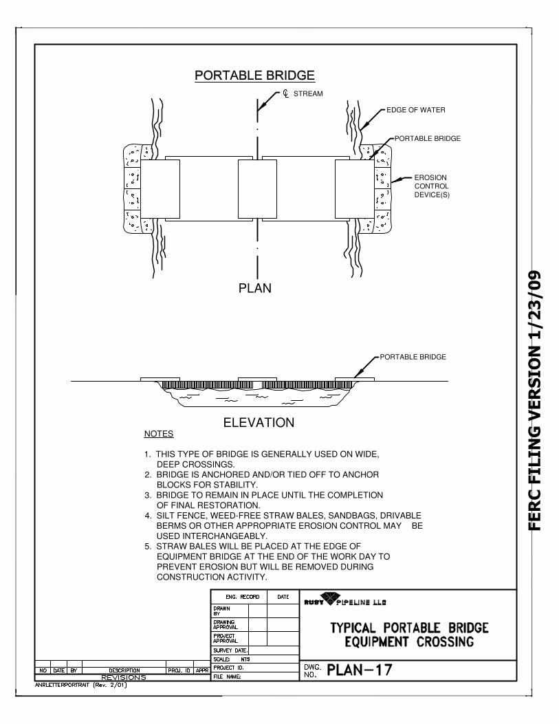
FERC FILING VERSION 1/23/09
NOTES
1. THIS TYPE OF BRIDGE IS GENERALLY USED ON WIDE,
DEEP CROSSINGS.
2. BRIDGE IS ANCHORED AND/OR TIED OFF TO ANCHOR
BLOCKS FOR STABILITY.
3. BRIDGE TO REMAIN IN PLACE UNTIL THE COMPLETION
OF FINAL RESTORATION.
4. SILT FENCE, WEED-FREE STRAW BALES, SANDBAGS, DRIVABLE
BERMS OR OTHER APPROPRIATE EROSION CONTROL MAY BE
USED INTERCHANGEABLY.
5. STRAW BALES WILL BE PLACED AT THE EDGE OF
EQUIPMENT BRIDGE AT THE END OF THE WORK DAY TO
PREVENT EROSION BUT WILL BE REMOVED DURING
CONSTRUCTION ACTIVITY.
ELEVATION
PLAN
STREAM
EDGE OF WATER
PORTABLE BRIDGE
EROSION
CONTROL
DEVICE(S)
PORTABLE BRIDGE
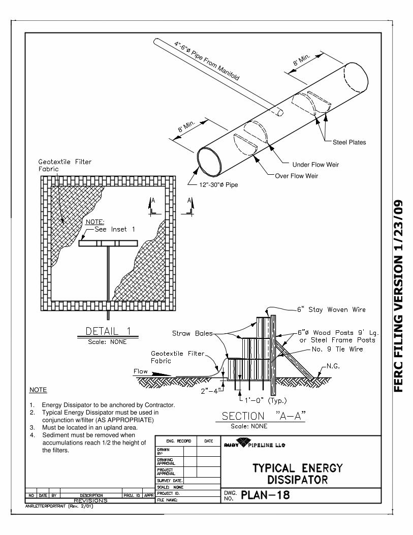
FERC FILING VERSION 1/23/09
4"-6" Pipe From Manifold
8' Min.
Steel Plates
Under Flow Weir
Over Flow Weir
12"-30" Pipe
8' Min.
NOTE
1. Energy Dissipator to be anchored by Contractor.2. Typical Energy Dissipator must be used in
conjunction w/filter (AS APPROPRIATE)3. Must be located in an upland area.
4. Sediment must be removed when
accumulations reach 1/2 the height of
the filters.
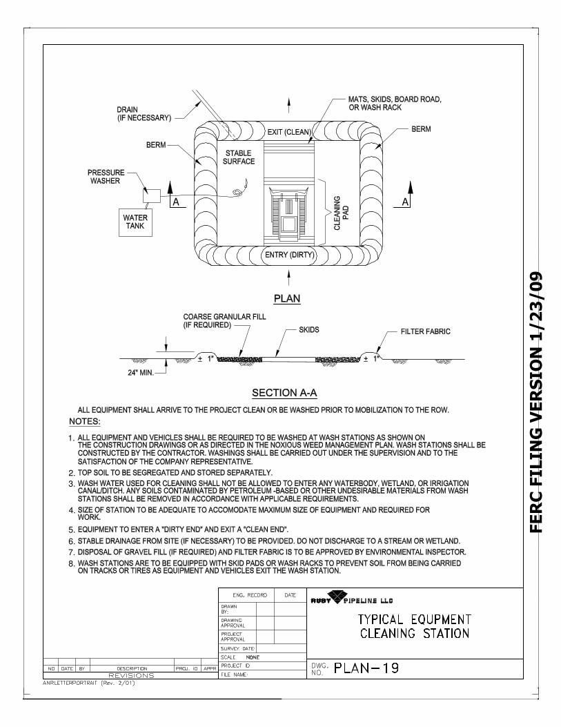
FERC FILING VERSION 1/23/09
1.
3.
4.
5.
6.
7.
8.
A A
2.

Minimum 36” of cover over pipeline
Quick
Time™
and a
deco
mpres
sor
are ne
eded
to se
e this
pictu
re.
QuickTime™ and a decompressor
are needed to see this picture.
Minimum 36” of cover over pipeline

QuickTime™ and a decompressor
are needed to see this picture.
Minimum 36” of cover over pipeline
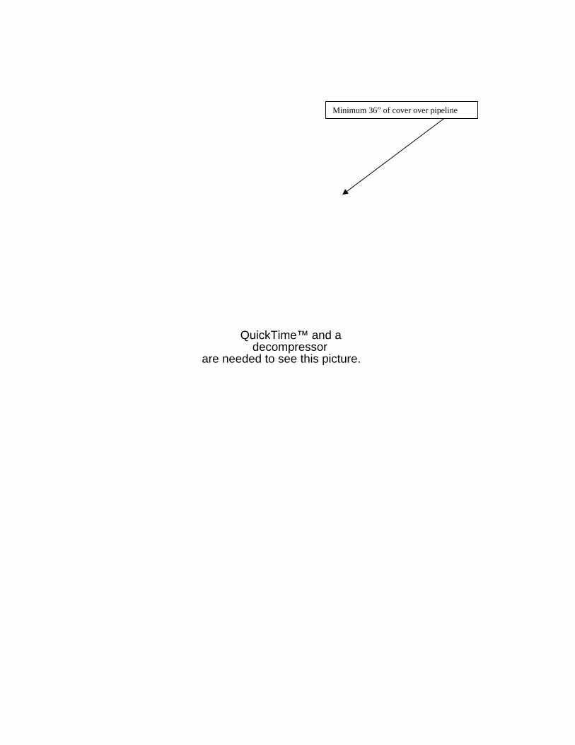
QuickTime™ and a decompressor
are needed to see this picture.
Minimum 36” of cover over pipeline

QuickTime™ and a decompressor
are needed to see this picture.
Minimum 36” of cover over pipeline

QuickTime™ and a decompressor
are needed to see this picture.
Minimum 36” of cover over pipeline

Minimum 36” of cover over pipeline
The remaining spoil material is featured out across the ROW prior to returning the topsoil. A gentle rise is left over the top of the ditch line to allow for any settling and to insure that rain or snow runoff does not start to channelize down the ditch line causing erosion or damage to the pipeline. Also, excess material is used to construct the stabilization water bars that are placed to slow runoff velocity and direct the excess moisture to existing undisturbed soils.
QuickTime™ and a decompressorare needed to see this picture.
QuickTime and a decompressor
are needed to see this picture.

Minimum 36” of cover over pipeline
QuickTime™ and a decompressor
are needed to see this picture.

TYPICAL OPEN CUT ROAD CROSSING
PLAN AND PROFILE
QuickTime™ and a decompressor
are needed to see this picture.