washington, dc 20585 oec 16 2015 - energy
TRANSCRIPT
Department of Energy Washington, DC 20585
OEC 16 2015
The Honorable Joyce L. Connery Chairman Defense Nuclear Facilities Safety Board 625 Indiana A venue NW, Suite 700 Washington, DC 20004
Dear Madam Chair:
Enclosed are the Depaiiment of Energy's (DOE) Office of Environmental Management summary and suppmiing report in response to the Defense Nuclear Facilities Safety Board's (Board) August 3, 2015, letter regarding analyses, controls, and path forward related to postulated flammability hazards at the Defense Waste Processing Facility (DWPF). The Board requested a rep01i that addresses: 1) DO E's analysis of interactions between non-safety and safety components in the melter off-gas system; 2) the adequacy of compensatory measures for the retained hydrogen Potential Inadequacy of Safety Analysis (PISA); and 3) the path forward for resolving the melter feed rate, retained hydrogen, and antifoam flammability PISAs.
To address these issues, Savannah River Remediation performed an assessment to analyze the interactions between the non-safety and safety components in the melter off-gas system; evaluated plant data to determine the adequacy of cmTent compensatory measures for the retained hydrogen PISA; and developed a path forward to resolve the melter feed rate, retained hydrogen, and antifoam flammability PISAs. The enclosures provide the details of these assessments and the path forward to resolve the PISAs. In addition, DOE briefed the Board on these topics on October 15, 2015.
I would also like to communicate my appreciation for the staff rep01i provided in your August 3, 2015, letter as well as the additional detail provided during the actual onsite reviews perf01med by your staff. These detailed reviews were conducted in a spirit of cooperation, and our subsequent actions will provide for an enhanced safety posture for DWPF. My staff will continue to inform your staff of results and schedules associated with the path forward described in the enclosures.
Ifyou have any fmiher questions, please contact me or Mr. James Hutton, Deputy Assistant Secretary for Safety, Security, and Quality Programs, at (202) 586-5151.
Sincerely,
Monica C. Regalbuto Assistant Secretary
for Environmental Management
Enclosures
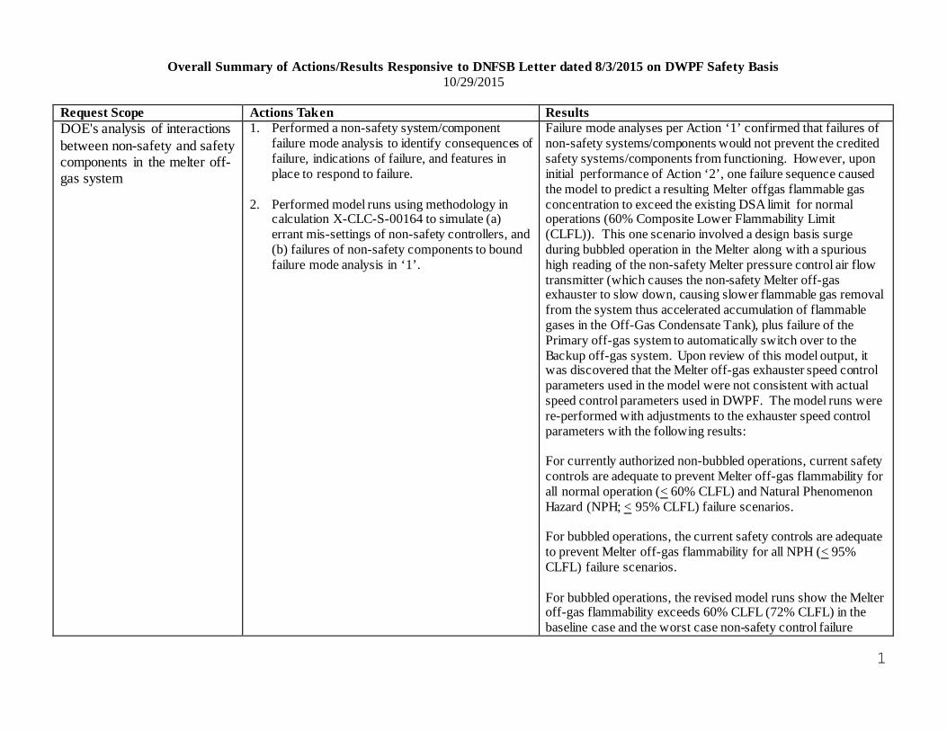
Overall Summary of Actions/Results Responsive to DNFSB Letter dated 8/3/2015 on DWPF Safety Basis 10/29/2015
Request Scope Actions Taken Results DOE's analysis of interactions 1. Performed a non-safety system/component Failure mode analyses per Action ‘1’ confirmed that failures of between non-safety and safety failure mode analysis to identify consequences of non-safety systems/components would not prevent the credited components in the melter off- failure, indications of failure, and features in safety systems/components from functioning. However, upon gas system place to respond to failure.
2. Performed model runs using methodology in calculation X-CLC-S-00164 to simulate (a) errant mis-settings of non-safety controllers, and (b) failures of non-safety components to bound failure mode analysis in ‘1’.
initial performance of Action ‘2’, one failure sequence caused the model to predict a resulting Melter offgas flammable gas concentration to exceed the existing DSA limit for normal operations (60% Composite Lower Flammability Limit (CLFL)). This one scenario involved a design basis surge during bubbled operation in the Melter along with a spurious high reading of the non-safety Melter pressure control air flow transmitter (which causes the non-safety Melter off-gas exhauster to slow down, causing slower flammable gas removal from the system thus accelerated accumulation of flammable gases in the Off-Gas Condensate Tank), plus failure of the Primary off-gas system to automatically switch over to the Backup off-gas system. Upon review of this model output, it was discovered that the Melter off-gas exhauster speed control parameters used in the model were not consistent with actual speed control parameters used in DWPF. The model runs were re-performed with adjustments to the exhauster speed control parameters with the following results:
For currently authorized non-bubbled operations, current safety controls are adequate to prevent Melter off-gas flammability for all normal operation (< 60% CLFL) and Natural Phenomenon Hazard (NPH; < 95% CLFL) failure scenarios.
For bubbled operations, the current safety controls are adequate to prevent Melter off-gas flammability for all NPH (< 95% CLFL) failure scenarios.
For bubbled operations, the revised model runs show the Melter off-gas flammability exceeds 60% CLFL (72% CLFL) in the baseline case and the worst case non-safety control failure
1
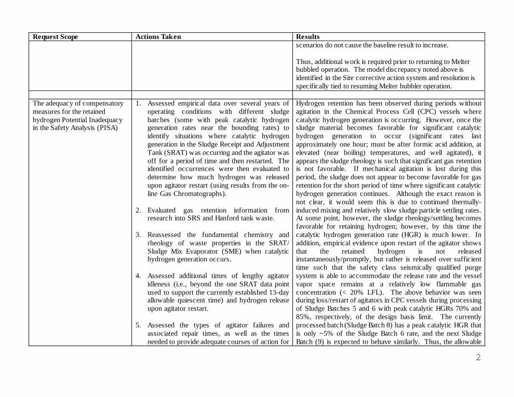
Request Scope Actions Taken Results scenarios do not cause the baseline result to increase.
Thus, additional work is required prior to returning to Melter bubbled operation. The model discrepancy noted above is identified in the Site corrective action system and resolution is specifically tied to resuming Melter bubbler operation.
The adequacy of compensatory measures for the retained hydrogen Potential Inadequacy in the Safety Analysis (PISA)
1. Assessed empirical data over several years of operating conditions with different sludge batches (some with peak catalytic hydrogen generation rates near the bounding rates) to identify situations where catalytic hydrogen generation in the Sludge Receipt and Adjustment Tank (SRAT) was occurring and the agitator was off for a period of time and then restarted. The identified occurrences were then evaluated to determine how much hydrogen was released upon agitator restart (using results from the on-line Gas Chromatographs).
2. Evaluated gas retention information from research into SRS and Hanford tank waste.
3. Reassessed the fundamental chemistry and rheology of waste properties in the SRAT/ Sludge Mix Evaporator (SME) when catalytic hydrogen generation occurs.
4. Assessed additional times of lengthy agitator idleness (i.e., beyond the one SRAT data point used to support the currently established 13-day allowable quiescent time) and hydrogen release upon agitator restart.
5. Assessed the types of agitator failures and associated repair times, as well as the times needed to provide adequate courses of action for
Hydrogen retention has been observed during periods without agitation in the Chemical Process Cell (CPC) vessels where catalytic hydrogen generation is occurring. However, once the sludge material becomes favorable for significant catalytic hydrogen generation to occur (significant rates last approximately one hour; must be after formic acid addition, at elevated (near boiling) temperatures, and well agitated), it appears the sludge rheology is such that significant gas retention is not favorable. If mechanical agitation is lost during this period, the sludge does not appear to become favorable for gas retention for the short period of time where significant catalytic hydrogen generation continues. Although the exact reason is not clear, it would seem this is due to continued thermally-induced mixing and relatively slow sludge particle settling rates. At some point, however, the sludge rheology/settling becomes favorable for retaining hydrogen; however, by this time the catalytic hydrogen generation rate (HGR) is much lower. In addition, empirical evidence upon restart of the agitator shows that the retained hydrogen is not released instantaneously/promptly, but rather is released over sufficient time such that the safety class seismically qualified purge system is able to accommodate the release rate and the vessel vapor space remains at a relatively low flammable gas concentration (< 20% LFL). The above behavior was seen during loss/restart of agitators in CPC vessels during processing of Sludge Batches 5 and 6 with peak catalytic HGRs 70% and 85%, respectively, of the design basis limit. The currently processed batch (Sludge Batch 8) has a peak catalytic HGR that is only ~5% of the Sludge Batch 6 rate, and the next Sludge Batch (9) is expected to behave similarly. Thus, the allowable
2
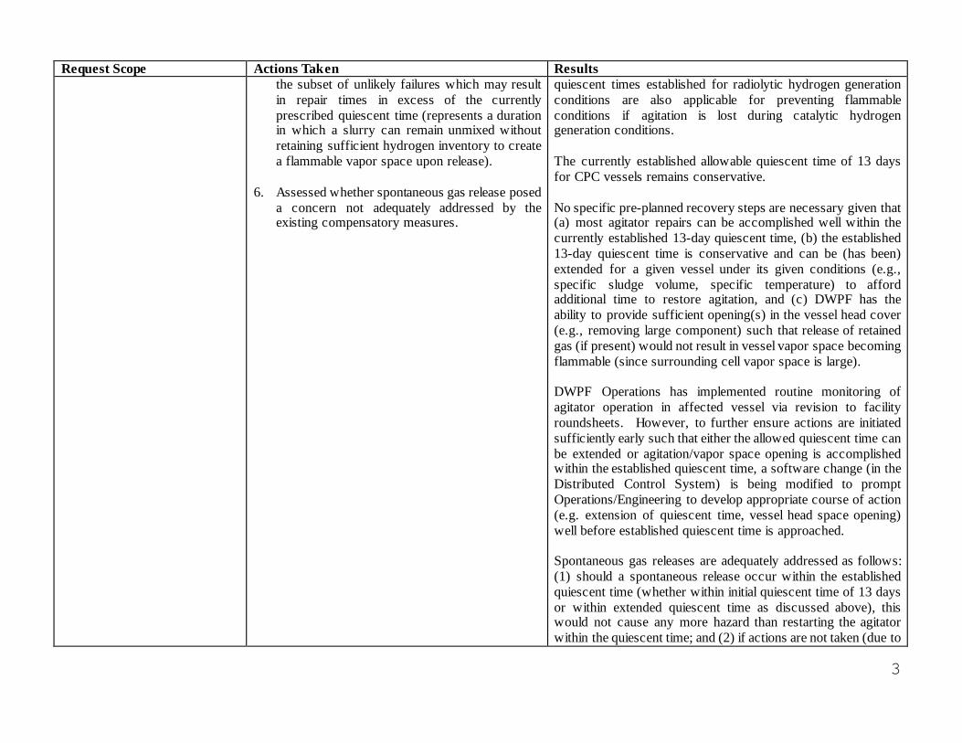
Request Scope Actions Taken Results the subset of unlikely failures which may result in repair times in excess of the currently prescribed quiescent time (represents a duration in which a slurry can remain unmixed without retaining sufficient hydrogen inventory to create a flammable vapor space upon release).
6. Assessed whether spontaneous gas release posed a concern not adequately addressed by the existing compensatory measures.
quiescent times established for radiolytic hydrogen generation conditions are also applicable for preventing flammable conditions if agitation is lost during catalytic hydrogen generation conditions.
The currently established allowable quiescent time of 13 days for CPC vessels remains conservative.
No specific pre-planned recovery steps are necessary given that (a) most agitator repairs can be accomplished well within the currently established 13-day quiescent time, (b) the established 13-day quiescent time is conservative and can be (has been) extended for a given vessel under its given conditions (e.g., specific sludge volume, specific temperature) to afford additional time to restore agitation, and (c) DWPF has the ability to provide sufficient opening(s) in the vessel head cover (e.g., removing large component) such that release of retained gas (if present) would not result in vessel vapor space becoming flammable (since surrounding cell vapor space is large).
DWPF Operations has implemented routine monitoring of agitator operation in affected vessel via revision to facility roundsheets. However, to further ensure actions are initiated sufficiently early such that either the allowed quiescent time can be extended or agitation/vapor space opening is accomplished within the established quiescent time, a software change (in the Distributed Control System) is being modified to prompt Operations/Engineering to develop appropriate course of action (e.g. extension of quiescent time, vessel head space opening) well before established quiescent time is approached.
Spontaneous gas releases are adequately addressed as follows: (1) should a spontaneous release occur within the established quiescent time (whether within initial quiescent time of 13 days or within extended quiescent time as discussed above), this would not cause any more hazard than restarting the agitator within the quiescent time; and (2) if actions are not taken (due to
3
Request Scope Actions Taken Results unforeseen circumstances) within the established quiescent time to restore agitation or open the vessel head space as discussed above, a spontaneous release after the established quiescent time and subsequent vessel explosion would not exceed the offsite or onsite evaluation guidelines as a result of the current compensatory measure restricting the material allowed to be processed in DWPF to 20% of the design basis inhalation dose potential (IDP).
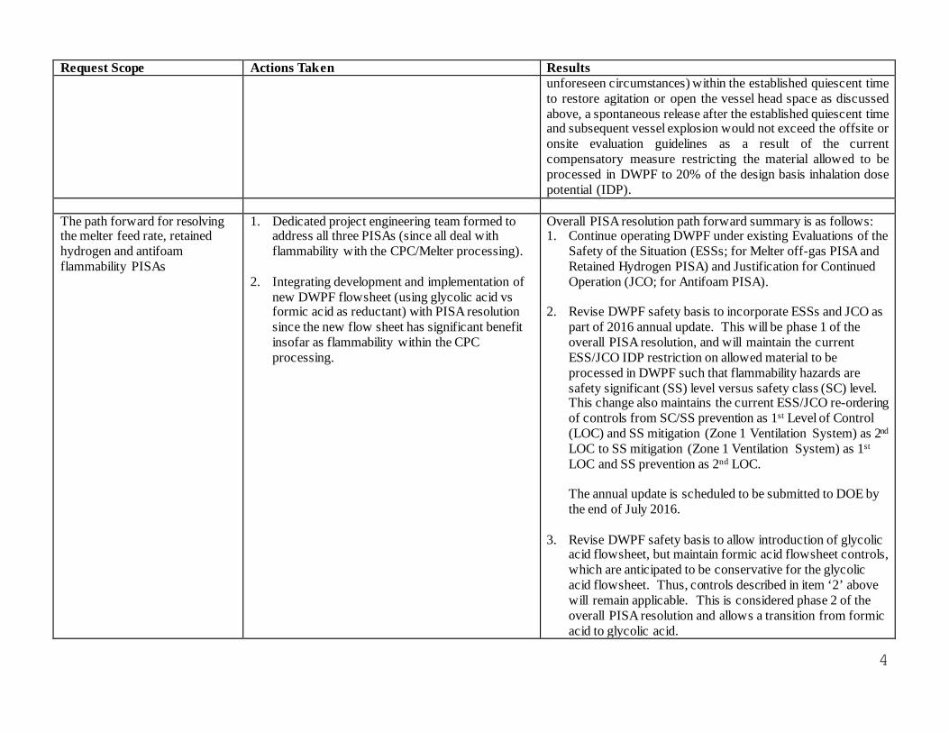
The path forward for resolving the melter feed rate, retained hydrogen and antifoam flammability PISAs
1. Dedicated project engineering team formed to address all three PISAs (since all deal with flammability with the CPC/Melter processing).
2. Integrating development and implementation of new DWPF flowsheet (using glycolic acid vs formic acid as reductant) with PISA resolution since the new flow sheet has significant benefit insofar as flammability within the CPC processing.
Overall PISA resolution path forward summary is as follows: 1. Continue operating DWPF under existing Evaluations of the
Safety of the Situation (ESSs; for Melter off-gas PISA and Retained Hydrogen PISA) and Justification for Continued Operation (JCO; for Antifoam PISA).
2. Revise DWPF safety basis to incorporate ESSs and JCO as part of 2016 annual update. This will be phase 1 of the overall PISA resolution, and will maintain the current ESS/JCO IDP restriction on allowed material to be processed in DWPF such that flammability hazards are safety significant (SS) level versus safety class (SC) level. This change also maintains the current ESS/JCO re-ordering of controls from SC/SS prevention as 1st Level of Control (LOC) and SS mitigation (Zone 1 Ventilation System) as 2nd
LOC to SS mitigation (Zone 1 Ventilation System) as 1st
LOC and SS prevention as 2nd LOC.
The annual update is scheduled to be submitted to DOE by the end of July 2016.
3. Revise DWPF safety basis to allow introduction of glycolic acid flowsheet, but maintain formic acid flowsheet controls, which are anticipated to be conservative for the glycolic acid flowsheet. Thus, controls described in item ‘2’ above will remain applicable. This is considered phase 2 of the overall PISA resolution and allows a transition from formic acid to glycolic acid.
4
Request Scope Actions Taken Results
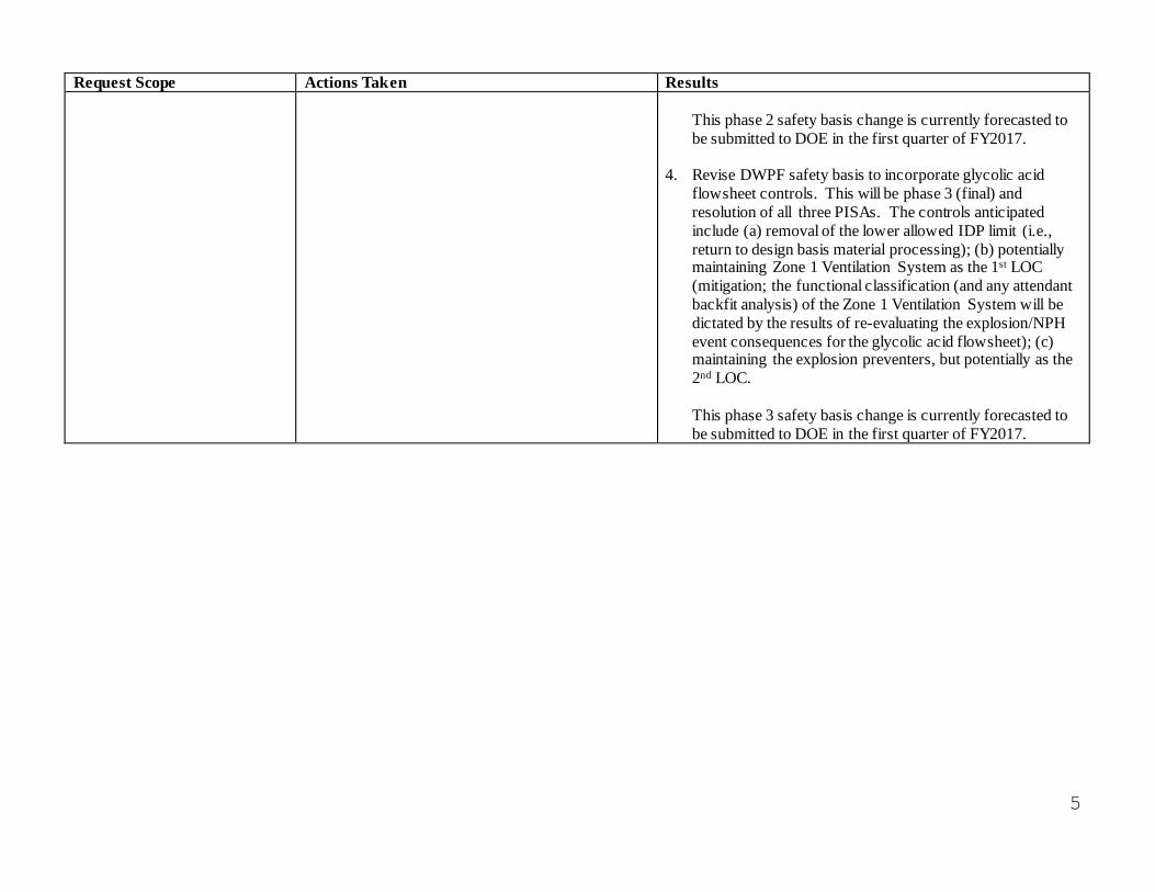
This phase 2 safety basis change is currently forecasted to be submitted to DOE in the first quarter of FY2017.
4. Revise DWPF safety basis to incorporate glycolic acid flowsheet controls. This will be phase 3 (final) and resolution of all three PISAs. The controls anticipated include (a) removal of the lower allowed IDP limit (i.e., return to design basis material processing); (b) potentially maintaining Zone 1 Ventilation System as the 1st LOC (mitigation; the functional classification (and any attendant backfit analysis) of the Zone 1 Ventilation System will be dictated by the results of re-evaluating the explosion/NPH event consequences for the glycolic acid flowsheet); (c) maintaining the explosion preventers, but potentially as the 2nd LOC.
This phase 3 safety basis change is currently forecasted to be submitted to DOE in the first quarter of FY2017.
5
X-ESR-S-00264 Rev. 0
Page 1 of 38
Keywords: DWPF, PISA, CPC, Retained Hydrogen, Melter, Off-Gas, LFL, Alternate Reductant
Input in Response to Defense Nuclear Facilities Safety Board Letter on Defense Waste Processing Facility Safety Basis

X-ESR-S-00264 Rev. 0
Pap2of38
Daip Veri6caliaa Mcdlod pi:r Jr1 2.oi:ft. "==-= .
Sm:liom Raviewd: 1.0. 2.0, 5.0, 6.0
I -.~Rpyi;W
0a1e: / oIlts:j u;
Daip Vcri6e11tiaa Medsod per E7, 2.60: Dpcpmept Revjew
Secdoas Reviewed: 1.0, 3.0, 4.0, s.o, 1.0
X-ESR-S-00264 Rev. 0
Page 3 of 38
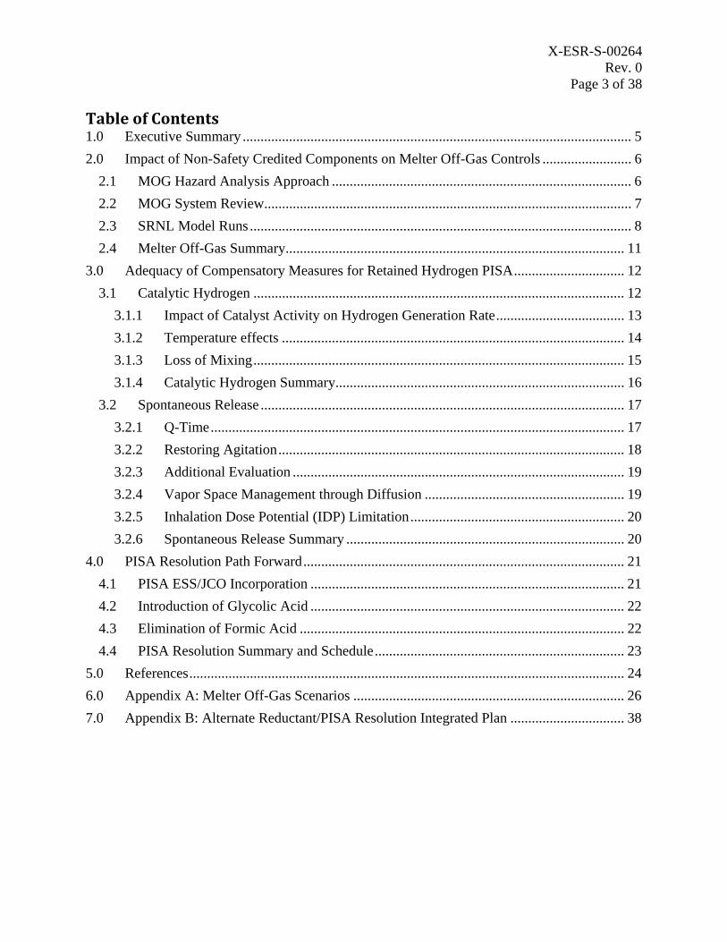
Table of Contents 1.0 Executive Summary ............................................................................................................. 5
2.0 Impact of Non-Safety Credited Components on Melter Off-Gas Controls ......................... 6
2.1 MOG Hazard Analysis Approach .................................................................................... 6
2.2 MOG System Review....................................................................................................... 7
2.3 SRNL Model Runs ........................................................................................................... 8
2.4 Melter Off-Gas Summary ............................................................................................... 11
3.0 Adequacy of Compensatory Measures for Retained Hydrogen PISA............................... 12
3.1 Catalytic Hydrogen ........................................................................................................ 12
3.1.1 Impact of Catalyst Activity on Hydrogen Generation Rate .................................... 13
3.1.2 Temperature effects ................................................................................................ 14
3.1.3 Loss of Mixing........................................................................................................ 15
3.1.4 Catalytic Hydrogen Summary ................................................................................. 16
3.2 Spontaneous Release ...................................................................................................... 17
3.2.1 Q-Time.................................................................................................................... 17
3.2.2 Restoring Agitation ................................................................................................. 18
3.2.3 Additional Evaluation ............................................................................................. 19
3.2.4 Vapor Space Management through Diffusion ........................................................ 19
3.2.5 Inhalation Dose Potential (IDP) Limitation ............................................................ 20
3.2.6 Spontaneous Release Summary .............................................................................. 20
4.0 PISA Resolution Path Forward .......................................................................................... 21
4.1 PISA ESS/JCO Incorporation ........................................................................................ 21
4.2 Introduction of Glycolic Acid ........................................................................................ 22
4.3 Elimination of Formic Acid ........................................................................................... 22
4.4 PISA Resolution Summary and Schedule...................................................................... 23
5.0 References.......................................................................................................................... 24
6.0 Appendix A: Melter Off-Gas Scenarios ............................................................................ 26
7.0 Appendix B: Alternate Reductant/PISA Resolution Integrated Plan ................................ 38
X-ESR-S-00264 Rev. 0
Page 4 of 38
List of Acronyms
CHAP Consolidated Hazard Analysis Process CPC Chemical Process Cell DOE Department of Energy DNFSB Defense Nuclear Facilities Safety Board DWPF Defense Waste Processing Facility DWTT Decontamination Waste Treatment Tank ESS Evaluation of the Safety of the Situation GR&R Gas Retention and Release HEME High Efficiency Mist Eliminator HEPA High Efficiency Particulate Air HLW High Level Waste JCO Justification for Continued Operation LFL Lower Flammability Limit LOC Level of Control MOG Melter Off-Gas NPH Natural Phenomena Hazard OGCT Off-Gas Condensate Tank PHR Process Hazards Review PISA Potential Inadequacy in the Safety Analysis SME Slurry Mix Evaporator SPC Salt Process Cell SRAT Sludge Receipt and Adjustment Tank SRNL Savannah River National Laboratory SRR Savannah River Remediation WSRC Westinghouse Savannah River Company
X-ESR-S-00264 Rev. 0
Page 5 of 38
1.0 Executive Summary
The Defense Nuclear Facilities Safety Board (DNFSB) has requested response on several topics related to the Defense Waste Processing Facility (DWPF) Safety Basis. Pursuant to the DNFSB request, the Department of Energy (DOE) directed Savannah River Remediation (SRR) to develop a report addressing several different subject areas [23]:
1. Confirmation that the potential failure modes of the non-safety components included in the Melter Off-Gas (MOG) dynamics model (calculation X-CLC-S-00164) do not invalidate the adequacy of the control set described in the current Documented Safety Analysis (DSA).
2. Confirmation of the adequacy of the current compensatory measures instituted as a result of the Potential Inadequacy in the Safety Analysis (PISA) on retained hydrogen, PI-2014-0013, including not having a specific recovery plan if agitation is lost in the SRAT or SME during catalytic hydrogen generation, and the potential for having a spontaneous gas release event during an agitation outage on any of the affected DWPF vessels.
3. Plan and schedule for resolving each of the current DWPF PISAs (Melter Feed Rate, Retained Hydrogen, Antifoam Degradation).
This report serves as a summary response to that request. The details specific to each subject area are described separately but can be briefly summarized:
A re-evaluation of non-safety components in the melter off-gas system did not identify a failure scenario in which the off-gas flammability potentials of the existing baseline cases would be exceeded. This re-evaluation did identify a discrepancy between the primary off-gas exhauster speed control parameters used in the MOG dynamics model and those of the facility. Correcting this discrepancy caused the peak H2/CO concentration to exceed 60% of the Lower Flammability Limit (LFL) for baseline bubbled operation (9X/5X surge basis). However, the correction did not result in the peak H2/CO concentration exceeding 60% of the LFL for the currently authorized non-bubbled operation (3X/3X surge basis). Further, no failure scenario considered caused the peak H2/CO concentration to exceed the DSA limit of 95% of the LFL for Natural Phenomena Hazard (NPH) events under either the bubbled or non-bubbled operation surge basis. In response to the model run results, the various control parameters used in the model will be further reviewed to ensure that the current facility configuration is accurately represented. Any necessary revisions to the model will be completed prior to returning to bubbled operation.
A thorough review of available DWPF process data did not identify significant volumes of trapped hydrogen during periods in which catalytic hydrogen retention was most favorable (post-acid addition, agitator de-energized, and elevated temperature).
There are a very small number of scenarios, involving an extended time without agitation, in which a spontaneous hydrogen release could challenge the lower flammability limit within DWPF vessels. DWPF Engineering has identified strategies to mitigate the potential impacts of spontaneous hydrogen release in those situations. These strategies have been previously demonstrated. The existing procedures for tracking
X-ESR-S-00264 Rev. 0
Page 6 of 38
agitator operation contain guidance to initiate these strategies to ensure sufficient response time should an agitator repair require extended downtime; however, DWPF Engineering is preparing a software change to the DCS that will add an additional prompt to the operator once an agitator has been off for a preset period of time.
There is a significant reduction in catalytic hydrogen generation, and there is reduction in the non-condensable gas surge in the melter, afforded by implementation of the new glycolic acid flowsheet and there is significant synergy between this flowsheet implementation and existing PISA resolution efforts. With this in mind, a dedicated project engineering team has been created to integrate safety basis development efforts needed to support implementation of a new glycolic acid flowsheet at DWPF as well as final closure of items related to the open PISAs. The team has developed a phased approach for implementation, summary schedule logic, and key milestones.
2.0 Impact of Non-Safety Credited Components on Melter Off-Gas Controls
The DNFSB review of the DWPF safety basis generated a question related to the interactions between non-safety and safety components in the MOG system. This led to a request by DOE for SRR to confirm that failure of a non-safety component included in the MOG dynamics model will not invalidate the adequacy of the control set described in the current DSA. An assessment of these non-safety components was completed by DWPF Engineering to address this question. In order to validate conclusions of this assessment, a Technical Task Request [1] was generated by SRR Engineering requesting Savannah River National Laboratory (SRNL) to perform several MOG dynamics model runs.
2.1 MOG Hazard Analysis Approach
Multiple Process Hazards Reviews (PHR) were conducted by DuPont and Bechtel personnel during the pre-design and early design stages of the DWPF using a “What-If” approach. This progressed through Westinghouse Savannah River Company (WSRC) to pre-operational and operational PHRs. Savannah River Site (SRS) subsequently replaced the PHRs with Consolidated Hazard Analysis Process (CHAPs) as outlined in manual SCD-11, Consolidated Hazard Analysis Process (CHAP) Program and Methods Manual.
From the CHAP Manual, the definition for Hazard Analysis (HA) is:
“The determination of material, system, process, and plant characteristics that can produce undesirable consequences, followed by the assessment of hazardous situations associated with a process or activity. Largely qualitative techniques are used to pinpoint weaknesses in design or operation of the facility that could lead to accidents. The hazard analysis examines the complete spectrum of potential accidents that could expose members of the public, workers, and the environment to hazardous materials and is performed throughout all stages of design (reference DOE-STD-3009-94, DOE-STD-1189-2008, 10CFR851). Hazards analysis consists of collecting information (hazardous material quantity, form and location; energy sources and potential initiating events; preventative and mitigative features) and a
X-ESR-S-00264 Rev. 0
Page 7 of 38
qualitative evaluation of the adequacy of controls in place to prevent hazardous material releases (reference DOE-STD-1027-92).”
This process was used to develop the initial PHRs for DWPF. These initial evaluations identified that an explosive mixture could potentially form in the MOG system with the loss of dilution air, loss of purge air, or loss of steam pressure to the film cooler. Events associated with off-gas components downstream of the Back-up and Primary Film Coolers were also evaluated for impact and determined not to require additional controls to protect the flammability in the MOG system.
2.2 MOG System Review
In conjunction with controlling the organic carbon concentrations in the Melter feed (LCO 3.1.8), the MOG flammability control (LCO 3.3.1) specifies requirements to prevent flammable conditions in the Melter and the Off-Gas system. The LCO 3.3.1 requirements include:
maintaining minimum vapor space temperature to ensure the majority of flammable gases generated are combusted in the melter
maintaining minimum air flow to the backup Film Cooler and the primary Film Cooler to ensure flammable gases generated are combusted and/or diluted before exiting the Film Cooler and entering the Off-Gas system
maintaining minimum steam pressure to ensure the measured air flow enters the melter system and does not exit through a rupture in the steam system
If any of these conditions are not satisfied, the safety class (SC) hardwired interlocks will shut off the melter feed pump to ensure that additional feed material is not introduced into the Melter, which prevents flammable conditions in the MOG system. An additional requirement of LCO 3.3.1 is that the melter must be aligned to the primary off-gas system while in Operation Mode. Operation of the melter feed pumps is prohibited by Distributed Control System (DCS) software interlocks and procedurally when the melter is not aligned to the primary off-gas system.
A CHAP approach similar to that used to develop the initial PHRs for DWPF was used by SRR Engineering to assess the impact to the adequacy of these MOG flammability controls due to failure of the non-safety components. Each non-safety component downstream of the primary Film Cooler was evaluated to identify failure scenarios, consequence of each scenario, indications available to recognize the occurrence of each scenario, and actions taken (either by operator, hardwire interlock, or software action) to mitigate the consequences. Based on these evaluations, a determination was made whether a failure of any of the non-safety components could potentially impact the adequacy of the current MOG flammability controls.
The failure of non-safety components in the backup MOG system was not evaluated because when the melter is aligned to the backup off-gas system, DCS software interlocks and melter feeding procedures prevent operation of the melter feed pump which prevents the delivery of feed to the melter. With no fresh feed coming in, both the source term for H2/CO and the off-gas surge tendency diminish, resulting in a reduced potential for off-gas flammability.
X-ESR-S-00264 Rev. 0
Page 8 of 38
The table in Appendix A shows the results of the evaluation process. As seen in Appendix A, failures of these non-safety components downstream of the back-up and primary Film Coolers do not impact the current MOG flammability controls. Also, Appendix A describes the defense in depth provided by the alarm response procedures (ARPs) to prevent/mitigate potential consequences of these failures. The majority of the ARPs require the facility to evaluate entry into LCO 3.3.1. The operator action required in these scenarios is to stop the melter feed pumps due to the primary MOG system not functioning as required and switchover to the backup off-gas system. Further, several of the alarms have non-safety software interlocks to either switch-over to the backup off-gas system and/or stop the melter feed pumps thus ensuring that additional feed material is not delivered to the melter. In addition, the current design and operating procedures prevent the melter feed pump from being operated without the DCS being operable as well as various transmitters, valves, switches, etc. that are not classified as safety components. This ensures that in the event of a total loss of the DCS, the Melter systems are placed in a safe condition until the DCS is restored. In summary, a failure of any one these non-safety components does not impact the minimum vapor space temperature, minimum combustion and dilution air flow, or minimum steam pressure requirements.
2.3 SRNL Model Runs
Although the qualitative review of the MOG system did not identify any impact from the non-safety components on the credited MOG flammability controls, SRNL was tasked to perform model runs to evaluate more subtle changes in the system dynamics and the transient chemical and thermodynamic conditions of the off-gas that might result from non-safety component failure scenarios identified as potentially having an impact on the safety basis. These model runs provided additional information for specific scenarios as outlined in Appendix A. The cases selected for model runs were chosen to simulate instances that could potentially have the most significant effect on the off-gas flammability controls. Cases 1 through 5 were chosen to determine the sensitivity of the off-gas system to changes in the Melter pressure control loop and the exhauster speed control loops and the subsequent reaction by the system. Cases 6 through 12 were selected due to these scenarios being identified as having the largest potential impact on the dynamic response of the off-gas system based on a qualitative review of the system response; these scenarios are identified in the table in Appendix A. An additional Case (Case 13) was a model run to determine the effects of the Case 10 failure scenario during a seismic event. In performing the SRNL model runs, the failure scenarios were assumed to occur simultaneously with the maximum melter off-gas surge event, as described in X-CLC-S-00164. Also, non-safety interlocks that would automatically initiate a switch-over to the back-up off-gas system and/or stop the melter feed pumps during these events were disabled.
Based on initial results from the SRNL model runs [2], only one of the non-safety component failure scenarios impacted the peak H2/CO concentrations in the Off-Gas Condensate Tank (OGCT) with respect to the baseline bubbled operation case. This one case (Case 10, involving the Control Air flow control loop failing high during Bubbled operation) resulted in the peak H2/CO concentration in the OGCT to exceed 60% during non-seismic conditions. None of the scenarios during non-bubbled operation and seismic event for bubbled and non-bubbled operation
X-ESR-S-00264 Rev. 0
Page 9 of 38
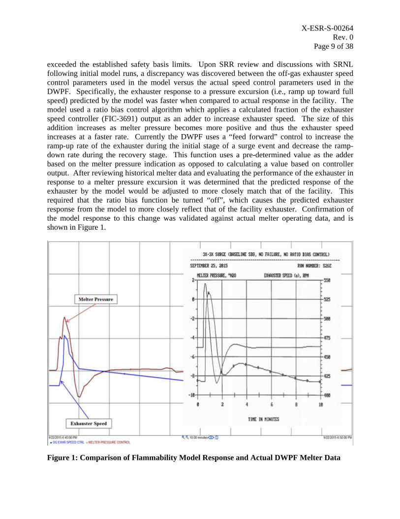
exceeded the established safety basis limits. Upon SRR review and discussions with SRNL following initial model runs, a discrepancy was discovered between the off-gas exhauster speed control parameters used in the model versus the actual speed control parameters used in the DWPF. Specifically, the exhauster response to a pressure excursion (i.e., ramp up toward full speed) predicted by the model was faster when compared to actual response in the facility. The model used a ratio bias control algorithm which applies a calculated fraction of the exhauster speed controller (FIC-3691) output as an adder to increase exhauster speed. The size of this addition increases as melter pressure becomes more positive and thus the exhauster speed increases at a faster rate. Currently the DWPF uses a “feed forward” control to increase the ramp-up rate of the exhauster during the initial stage of a surge event and decrease the ramp-down rate during the recovery stage. This function uses a pre-determined value as the adder based on the melter pressure indication as opposed to calculating a value based on controller output. After reviewing historical melter data and evaluating the performance of the exhauster in response to a melter pressure excursion it was determined that the predicted response of the exhauster by the model would be adjusted to more closely match that of the facility. This required that the ratio bias function be turned “off”, which causes the predicted exhauster response from the model to more closely reflect that of the facility exhauster. Confirmation of the model response to this change was validated against actual melter operating data, and is shown in Figure 1.
Figure 1: Comparison of Flammability Model Response and Actual DWPF Melter Data
X-ESR-S-00264 Rev. 0
Page 10 of 38
New model runs [2], including new baseline steady state and surge runs (both bubbled and non-bubbled operation), were then performed with the adjustments to the exhauster speed control parameters, with the following results.
For the non-bubbled baseline surge case, the peak H2/CO concentrations in the OGCT predicted a % LFL of 53% which is below the safety basis limit of 60% of the LFL for normal operation. This is expected due to the lower off-gas surge magnitudes that are seen during non-bubbled operation of the melter. In order to validate the model efficacy during non-bubbled operations, SRNL Case 14 and Case 15 were run using the non-bubbled surge basis to determine if the response of the model to the failure scenarios was sensitive to the use of the non-bubbled bounding surge event and to determine if the % LFL remained below the 60% limit for normal operation. As seen in Table 1, the results confirm that as expected, the % LFL for each case remained below 60%. This is important due to the fact that DWPF is currently prohibited from bubbled operation due to an open PISA [20], hence it is appropriate to utilize the non-bubbled surge basis (3X/3X) as the baseline surge case for current DWPF operations.
Additionally, no failure scenario resulted in a peak H2/CO concentration that exceeded the DSA limit of 95% of the LFL for NPH events under either bubbled or non-bubbled operation surge basis.
For bubbled normal operation, correcting the discrepancy between the off-gas exhauster speed control parameters used in the model versus the actual speed control parameters used in the DWPF resulted in the baseline off-gas surge case (9X/5X) peak H2/CO concentrations in the OGCT exceeding the safety basis limit of 60% of the LFL. Activities related to the open PISA already exist to perform a validation and recalibration of the MOG dynamics model under bubbled operations. The model will be revised accordingly based on these activities prior to resuming bubbled operation.
As shown in Table 1, the corrected model also showed that none of the various non-safety failure scenarios predicted that the peak H2/CO concentrations in the OGCT resulted in a % LFL greater than the baseline off-gas surge case. Table 1 provides the ratio of the peak flammability in terms of % LFL under each failure scenario to that of the applicable baseline case. As seen in the table, the ratios of Cases 1 through 12, 14, and 15 are at or below 1.01 for the normal bubbled and non-bubbled operation confirming that these scenarios do not impact the melter off-gas flammability. It is noted that the 1% increase is deemed to be negligible and has no impact on the flammability. Further, the ratio for Case 13 (1.14) is well below the corresponding normal-to-seismic operation safety basis limit ratio of 1.58 (=95%/60% LFL). This supports the conclusion made by SRR Engineering based on the qualitative evaluation shown in Appendix A: failure of any non-safety component within the MOG system will not impact the melter flammability controls.
The results of the model runs showed that under the current MOG configuration that the speed of the primary exhauster could impact the predicted % LFL in the OGCT. In order to further determine the potential impact of the primary off-gas exhauster speed on the peak H2/CO concentrations in the OGCT for the baseline non-bubbled surge case, additional model runs were performed to establish the peak flammability versus exhauster speed. This was accomplished by
X-ESR-S-00264 Rev. 0
Page 11 of 38
completing model runs where a surge (time: t=0) occurs simultaneously with the exhauster speed controller being set in MANUAL to a single speed. The speeds ranged from 350 to 1200 rpm. The manual setpoint kept the exhauster speed constant throughout the entire duration of the surge scenario (t=0 through t=8 minutes). The highest % LFL under these scenarios was observed at an exhauster speed of approximately 800 rpm and remained below the safety basis limit of 60% of the LFL.
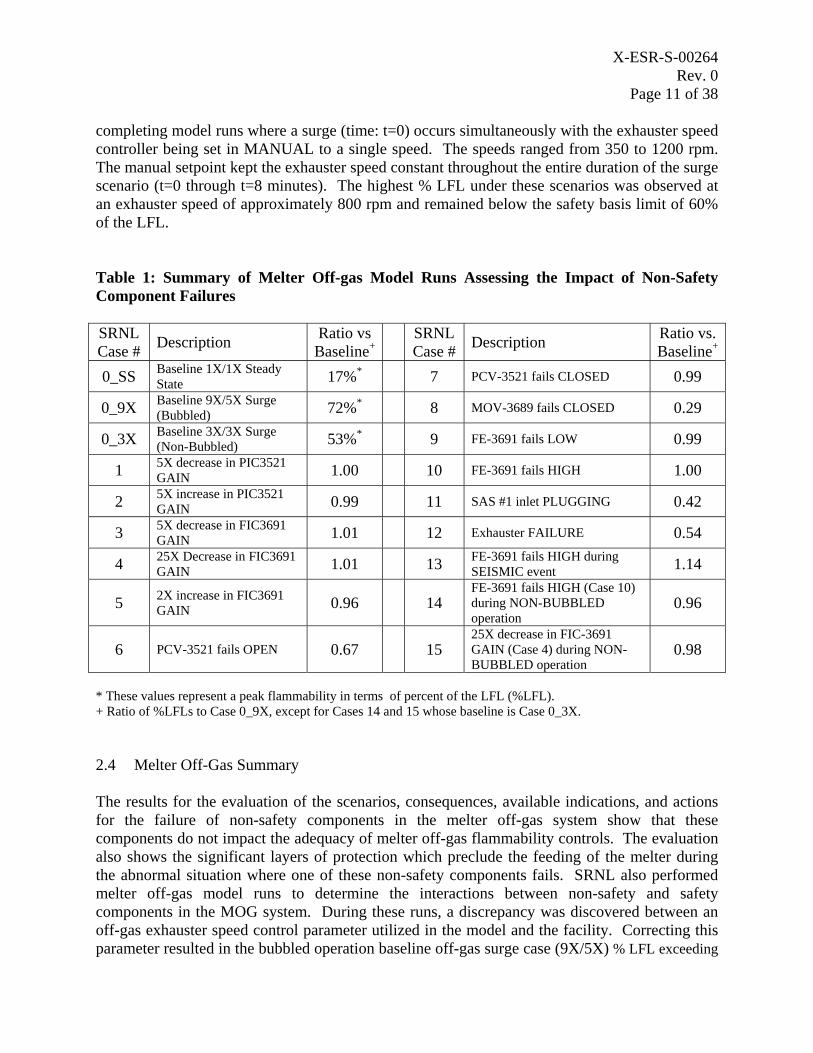
Table 1: Summary of Melter Off-gas Model Runs Assessing the Impact of Non-Safety Component Failures
SRNL Case # Description Ratio vs
Baseline+ SRNL
Case # Description Ratio vs. Baseline+
0_SS Baseline 1X/1X Steady State 17%* 7 PCV-3521 fails CLOSED 0.99
0_9X Baseline 9X/5X Surge (Bubbled) 72%* 8 MOV-3689 fails CLOSED 0.29
0_3X Baseline 3X/3X Surge (Non-Bubbled) 53%* 9 FE-3691 fails LOW 0.99
1 5X decrease in PIC3521 GAIN 1.00 10 FE-3691 fails HIGH 1.00
2 5X increase in PIC3521 GAIN 0.99 11 SAS #1 inlet PLUGGING 0.42
3 5X decrease in FIC3691 GAIN 1.01 12 Exhauster FAILURE 0.54
4 25X Decrease in FIC3691 GAIN 1.01 13 FE-3691 fails HIGH during
SEISMIC event 1.14
5 2X increase in FIC3691 GAIN 0.96 14
FE-3691 fails HIGH (Case 10) during NON-BUBBLED operation
0.96
6 PCV-3521 fails OPEN 0.67 15 25X decrease in FIC-3691 GAIN (Case 4) during NON-BUBBLED operation
0.98
* These values represent a peak flammability in terms of percent of the LFL (%LFL). + Ratio of %LFLs to Case 0_9X, except for Cases 14 and 15 whose baseline is Case 0_3X.
2.4 Melter Off-Gas Summary
The results for the evaluation of the scenarios, consequences, available indications, and actions for the failure of non-safety components in the melter off-gas system show that these components do not impact the adequacy of melter off-gas flammability controls. The evaluation also shows the significant layers of protection which preclude the feeding of the melter during the abnormal situation where one of these non-safety components fails. SRNL also performed melter off-gas model runs to determine the interactions between non-safety and safety components in the MOG system. During these runs, a discrepancy was discovered between an off-gas exhauster speed control parameter utilized in the model and the facility. Correcting this parameter resulted in the bubbled operation baseline off-gas surge case (9X/5X) % LFL exceeding
X-ESR-S-00264 Rev. 0
Page 12 of 38
the safety basis limit of 60% for normal operation. The failure scenario cases were also re-run with the corrected speed control; the results showed no negative impacts to melter off-gas flammability due to these failures. Further, no failure scenario resulted in a peak %LFL that exceeded the DSA limit of 95% for NPH events under either bubbled or non-bubbled operation surge basis. Because the DWPF is currently only authorized to be in non-bubbled operation, a model run was performed for the non-bubbled baseline surge case (3X/3X). For this case, the predicted % LFL was 53% which is below the safety basis limit of 60% of the LFL for normal operation. This demonstrated that the safety basis limits will not be exceeded under the existing TSR and feed interlock limits if any of the failure scenarios considered occurs during either non-bubbled operation or a seismic event.
3.0 Adequacy of Compensatory Measures for Retained Hydrogen PISA
The DOE request pertaining to the retained hydrogen PISA focused on two key subject areas: the lack of a specific recovery plan if agitation is lost in the SRAT or SME during catalytic hydrogen generation, and the potential for having a spontaneous gas release event during an extended agitation outage of any affected DWPF process vessel(s). These topics are considered separately below.
3.1 Catalytic Hydrogen
DWPF Engineering has performed an evaluation to bound the potential for trapped hydrogen release following periods in which mechanical agitation of the sludge slurry is unavailable [3]. This empirically-based evaluation noted that with the current sludge material, a quiescent time (or “q-time”) of 13 days did not result in a hydrogen release (upon re-initiation of mechanical agitation) sufficient to reach flammable conditions in vessel vapor spaces. In fact, Reference 3 shows that even after 13 days of non-agitation, the resulting release of retained hydrogen caused the vessel vapor space to reach < 2% LFL. The results of this evaluation apply generally to settled sludges within DWPF which generate hydrogen due to radiolytic decomposition of water into molecular oxygen and hydrogen.
However, DWPF has a separate and more vigorous method of hydrogen generation that is based on chemical interactions during chemical process cell operations. Formic acid used in chemical adjustment can decompose in the presence of activated noble metals at elevated temperature to form gaseous hydrogen. Due to the quantity of excess formic acid and favorable initial kinetics, the rate of catalytic hydrogen generation can exceed radiolytic hydrogen generation by several orders of magnitude [4]. The data for the current 13-day quiescent time evaluation was taken from a period of process downtime during which a new sludge transfer into DWPF had been completed, but prior to the addition of any formic acid. As a result, the evaluation provides a representative basis for retention and release of radiolytic hydrogen, but it does not consider the impact of a loss-of-agitation event during catalytic hydrogen generation. Since the catalytic rates are generally much higher, the acceptable q-time might be much shorter. Therefore, DWPF Engineering has evaluated the potential for retention of catalytically generated hydrogen.
X-ESR-S-00264 Rev. 0
Page 13 of 38
Although a substantial amount of research into the mechanisms of gas retention and release (GR&R) has been performed over the last 25 years, it is difficult to find experimental data sets that are directly applicable to the conditions of the DWPF Chemical Process Cell (CPC). Much of the previous work has been focused on gas retention under conditions experienced within High Level Waste (HLW) storage tanks at both Savannah River Site and Hanford [5, 6, and 7]. While some generic trends can likely be applied, the very different hydrostatic pressures and sludge rheologies in those environments limits the direct application for DWPF CPC vessels. Experimental work has also been performed as part of development of the Hanford Waste Treatment Plant. This effort includes GR&R data over some sludge rheologies that are representative of DWPF slurries [12, 13, and 14], but substantial differences remain in method of vessel agitation, amount and composition of antifoam agents, vessel size and geometry, and the mechanism of bubble formation. As a result, it does not appear at present that sufficient experimental data exists to attempt to extrapolate accurate q-times for implementation into a facility response program.
Instead, DWPF has performed an empirical evaluation using facility data consistent with the methodology of Ref. 3. The evaluation analyzed a comprehensive data set over several years of operation and several different sludge batches [11]. The data was sorted to identify periods during the operation of the CPC when mechanical agitation was lost and retention of catalytic hydrogen would be most probable, specifically after formic acid addition and at elevated vessel temperatures. After screening, 158 potential events were identified of which only 18 were observed to have a measureable difference in GC readings from pre-acid addition readings. While this evaluation did identify a limited number of events where a small hydrogen release was detected upon agitator restart, the size of the releases were much smaller than would be anticipated if even moderate fractions of the total peak catalytic hydrogen generated were being retained within the sludge. All of the events occurred during processing of Sludge Batches 5 and 6, which produced catalytic hydrogen at near-design-basis rates and bound all other sludge rheologies in DWPF process history. Recent sludge batches (including the current one) have produced much lower quantities of catalytically-generated hydrogen, between 3-5% of the rates observed in Sludge Batch 6 [11]. As a result, the primary conclusion is that there is no obvious evidence for significant catalytic hydrogen retention. This observation seems consistent with several principles of CPC operation, considered separately below, that would suggest retention of catalytic hydrogen is limited to small quantities.
3.1.1 Impact of Catalyst Activity on Hydrogen Generation Rate
Catalytic decomposition of formic acid is a fundamental feature of the current DWPF process which has been studied extensively over the years. Many factors have been studied to determine the impact on the magnitude and duration of formic acid decomposition. One phenomenon which has been repeatedly demonstrated has been the transient nature of catalytic generation. There are a variety of metals within SRS sludges (e.g., ruthenium, palladium, rhodium, nickel, silver, etc.) that can support formic acid decomposition within DWPF. However, simulant and real waste testing has repeatedly shown that once metals have become sufficiently active to generate hydrogen, they also begin to react with other chemical species that ultimately leads to degradation in their catalytic behavior for hydrogen generation. This phenomenon is referred to
X-ESR-S-00264 Rev. 0
Page 14 of 38
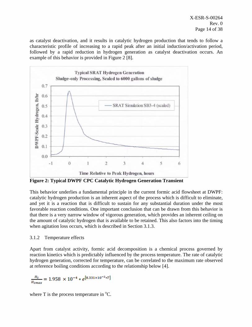
as catalyst deactivation, and it results in catalytic hydrogen production that tends to follow a characteristic profile of increasing to a rapid peak after an initial induction/activation period, followed by a rapid reduction in hydrogen generation as catalyst deactivation occurs. An example of this behavior is provided in Figure 2 [8].
Figure 2: Typical DWPF CPC Catalytic Hydrogen Generation Transient
This behavior underlies a fundamental principle in the current formic acid flowsheet at DWPF: catalytic hydrogen production is an inherent aspect of the process which is difficult to eliminate, and yet it is a reaction that is difficult to sustain for any substantial duration under the most favorable reaction conditions. One important conclusion that can be drawn from this behavior is that there is a very narrow window of vigorous generation, which provides an inherent ceiling on the amount of catalytic hydrogen that is available to be retained. This also factors into the timing when agitation loss occurs, which is described in Section 3.1.3.
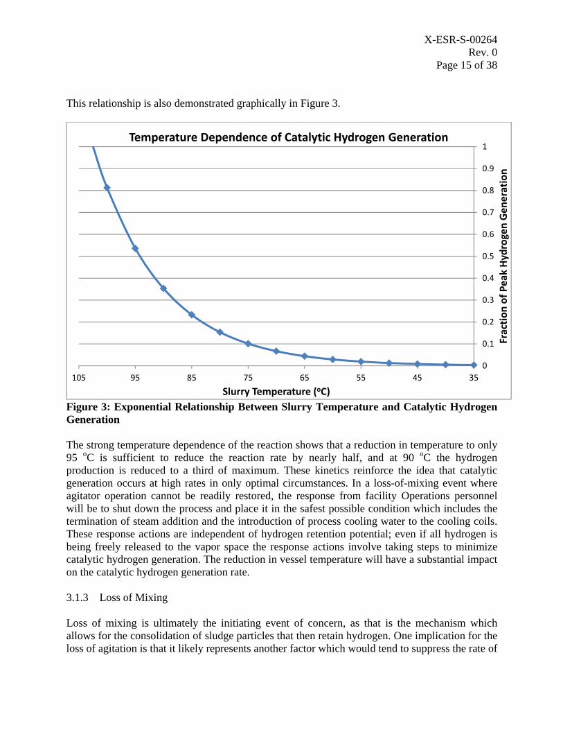
3.1.2 Temperature effects
Apart from catalyst activity, formic acid decomposition is a chemical process governed by reaction kinetics which is predictably influenced by the process temperature. The rate of catalytic hydrogen generation, corrected for temperature, can be correlated to the maximum rate observed at reference boiling conditions according to the relationship below [4].
where T is the process temperature in oC.
X-ESR-S-00264 Rev. 0
Page 15 of 38
This relationship is also demonstrated graphically in Figure 3.
0
0.1
0.2
0.3
0.4
0.5
0.6
0.7
0.8
0.9
1
35455565758595105
Fraction
of P
eak
Hydrogen
Generation
Slurry Temperature (oC)
Temperature Dependence of Catalytic Hydrogen Generation
Figure 3: Exponential Relationship Between Slurry Temperature and Catalytic Hydrogen Generation
The strong temperature dependence of the reaction shows that a reduction in temperature to only 95 oC is sufficient to reduce the reaction rate by nearly half, and at 90 oC the hydrogen production is reduced to a third of maximum. These kinetics reinforce the idea that catalytic generation occurs at high rates in only optimal circumstances. In a loss-of-mixing event where agitator operation cannot be readily restored, the response from facility Operations personnel will be to shut down the process and place it in the safest possible condition which includes the termination of steam addition and the introduction of process cooling water to the cooling coils. These response actions are independent of hydrogen retention potential; even if all hydrogen is being freely released to the vapor space the response actions involve taking steps to minimize catalytic hydrogen generation. The reduction in vessel temperature will have a substantial impact on the catalytic hydrogen generation rate.
3.1.3 Loss of Mixing
Loss of mixing is ultimately the initiating event of concern, as that is the mechanism which allows for the consolidation of sludge particles that then retain hydrogen. One implication for the loss of agitation is that it likely represents another factor which would tend to suppress the rate of
X-ESR-S-00264 Rev. 0
Page 16 of 38
formic acid decomposition. The factors above show that under anything other than optimum conditions (maximum catalyst activity and slurry temperature) it is unlikely for catalytic hydrogen generation to occur at a rapid rate. Free and unreacted formic acid is well mixed into solution immediately after introduction to the vessel, and constant mechanical agitation helps to ensure maximum contact between active catalyst sites and available acid molecules. Once this mixing force is removed, some mass transfer limitations would appear which would inhibit the overall rate of reaction. On the small scale, catalyst sites will tend to deplete the available local concentration of formic acid which will not then be as readily replenished as would occur with good mixing. On large scales (and over a longer duration), the settling of suspended particles will result in a concentration gradient of catalyst sites towards the bottom of the vessel, corresponding to local depletion in these areas of unreacted formic acid. These trends are not readily demonstrated like the previous topics as they represent results from unplanned facility events and are not relevant to demonstration of routine process operations in a laboratory environment. Some data taken during interrupted experimental runs could conceivably help to quantify the effects, but very often such data would be unreported as it does not support typical sludge batch qualification activities. Thus, it is not possible presently to quantify the impact this would have on hydrogen generation with experimental data, although the affect could result in a reduction in catalytic hydrogen generation rate by as much as an order of magnitude [8].
The second implication for loss of mixing affects the timing of events in a potential upset scenario. The concerning event is initiated by either a mechanical or electrical failure of the vessel agitator which results in subsequent settling of insoluble solids and retention of catalytically generated hydrogen. However, the nature of the DWPF process makes it unlikely for these two things to happen simultaneously. As described above, the most significant quantity of catalytic hydrogen is generated in a short window of time, which occurs within the first couple of hours after the addition of formic acid. Should an agitator fail before the catalyst is sufficiently activated, there is minimal or no reaction. Thus, the scenario requires that all acid be successfully added to the tank, and that well-mixed, boiling conditions have been sustained long enough to cause catalyst activation in the vessel. Should agitator failure occur at that time, it must still be acknowledged that complete loss of particle momentum in the slurry and subsequent settling does not occur immediately. The suspended sludge particles will remain in motion for some period of time before losing velocity and falling. The rate at which this happens will be dependent on a number of factors including slurry level, solids content, and apparent viscosity. During startup testing of the Melter Feed Tank, it was noted that statistically significant compositional differences due to insufficient agitation required on the order of tens of hours to be observed [9] and settling studies of untreated Tank Farm sludges have shown settling times of several days as well [10]. However, the effect is again difficult to quantify and lab scale experimental work has shown that gas retention may yet start relatively soon after mixing is lost [21].
3.1.4 Catalytic Hydrogen Summary
DWPF Engineering conducted an extensive review of experimental literature and facility data to assess the potential for process slurries to retain substantial quantities of hydrogen generated by the catalytic decomposition of formic acid. The data available from experimental work has very
X-ESR-S-00264 Rev. 0
Page 17 of 38
limited application to the conditions relevant to the DWPF CPC vessels and extrapolation from that data set is not likely to be reliable. However, the previous qualitative consideration of the principles of DWPF operation suggests that retention of catalytically generated hydrogen is limited due to a number of factors related to the chemical mechanism and sequencing of process operations and minimal catalytic activity of recent sludges. This expectation is reinforced by an extensive review of process operating data. Of the 158 cases where retention of catalytically generated hydrogen was most probable, the review identified only eighteen occasions where any retained hydrogen was detected, and in amounts that imply either a very low generation rate, minimal gas retention, relatively low release rate upon agitation, or some combination of all three [11]. Thus, the conservative established q-time for non-catalytic conditions in CPC vessels can be applied for loss of agitation events during catalytic hydrogen generation conditions.
3.2 Spontaneous Release
One of the primary purposes of the existing compensatory measures for the trapped gas PISA is to ensure that once tank agitation has been lost or secured, an engineering evaluation that verifies a trapped gas release will not cause the tank vapor space to reach LFL will be performed prior to agitating the settled sludge. However, research into GR&R behavior [5, 7] as well as operating data from Hanford and Savannah River Site has shown that mechanisms exist where trapped gases may be spontaneously released from settled sludges without mechanical agitation. Seismic events, buoyant displacements, and gas percolation are all mechanisms by which accumulated gases may be released to a vessel vapor space independently of mechanical agitation.
3.2.1 Q-Time
As part of the compensatory measures developed for the trapped gas PISA, restarting an agitator that had been stopped for greater than one hour was prohibited without further engineering evaluation [15]. The one hour q-time of this compensatory measure was adopted due to the uncertainty about gas generation and retention rates at the time the PISA was declared. Subsequent work has determined that much longer quiescent periods are acceptable, and the generic q-time for current DWPF sludge has now been established as 13 days [3]. This is a longer quiescent duration with a much smaller retained gas release than previous experimental work would predict. An assessment of q-time in the Low Point Pump Pit Sludge Tank for Sludge Batch 3 predicted that a trapped hydrogen release could reach 100% LFL after 11 days of settling [21], and this potential has been re-assessed (while maintaining the original assumption of 100% retention) for the higher radiolytic hydrogen generation rates of Sludge Batch 8 [22]. Both of these calculations would predict a substantial hydrogen release after the resuspension of sludge that has settled for only a few days, a phenomenon that has not been empirically supported by observation of facility operations. This underscores the magnitude of conservativism that results when current lab-scale experimental data for gas retention and release are extrapolated to full-scale facility operation.
Regardless of the bases used for determining q-times, the overall philosophy of their use is the same: to define a time interval during which it is not possible to accumulate a quantity of retained gas which could cause a vessel to reach flammable conditions upon release. While a q-
X-ESR-S-00264 Rev. 0
Page 18 of 38
time program does not prevent spontaneous releases of retained gas, it does bound the problem in such a manner that only releases occurring beyond the defined q-time interval are of concern. This provides an opportunity for deliberate actions, prior to exceeding a q-time, to mitigate the event. These deliberate actions, namely restoring agitation, extending the q-time, or unsealing the vapor space, are discussed below.
3.2.2 Restoring Agitation
There are a large number of causes within DWPF which can lead to a loss of agitation within vessels where gas retention is possible. Loss of agitation can be identified during process monitoring, collection of operator roundsheet data, or via DCS alarm for some vessels. These outage periods can generally be classified based on the time needed to restore agitation: short (minutes to hours), intermediate (hours to several days), and long term (days to weeks). Short duration events can occur for a wide variety of reasons. Temporary loss of power, the direct action of an operator, and routinely scheduled preventive maintenance are all initiators which could lead to the cessation of vessel mixing for a brief period. These events are not generally caused by substantial equipment failures or malfunctions and are essentially always able to be resolved without approaching a vessel q-time. Depending on facility operations, events like these could occur multiple times in a given month, or tens of events each year.
Intermediate duration events have substantially fewer causes, and are almost all related to a mechanical or electrical fault with the agitator. Shaft decoupling, gearbox failure, variable frequency drive failure, and agitator motor failures are all unplanned events which require a moderate amount of troubleshooting and work planning to resolve. Though some repairs (like a major mechanical overhaul) could take several weeks to plan and execute, the restoration of vessel agitation would occur much more quickly as the facility maintains spare equipment and many major mechanical items are interchangeable between several vessels. As a result, these events can be resolved within existing q-times. Since these events are primarily driven by equipment failure, they occur much less frequently and can be estimated based on previous facility maintenance history. The likelihood for agitator failure for a particular vessel in a given year is relatively low, but given the large number of vessels involved, the likelihood of agitator failure increases to between one and three such events annually within DWPF.
The rarest events are those whose repair duration cannot be mitigated by maintaining available spare equipment. These events are generally caused by an external failure which would be upstream of the agitator itself and thus common to any spare component. Examples include damage to the remote power supply jumper which connects the agitator motor to the wall, cable failure within the wall, or mechanical damage or interference to the mounting at the tank top which prevents successful installation of an agitator into the tank. Given the relatively low number of causes, these types of events have happened only rarely during DWPF’s history and might be expected to occur once every three to five years. One recent example of such an event occurred in mid-2015 when the wiring between the agitator motor on the Decon Waste Treatment Tank (DWTT) and the power jumper shorted out and fused together. Removal of the jumper resulted in damage to the cabling, requiring new wire be pulled through both the jumper and through-wall conduit to a termination box on the third level of DWPF. Due to the complex
X-ESR-S-00264 Rev. 0
Page 19 of 38
nature of the task and resources needed to execute the repair, it took 17 days from the initial failure to restore agitation to the DWTT. In this particular case an Engineering evaluation of the specific conditions concluded that the q-time was infinite, but the 17-day duration exceeded the currently defined 13 day q-time in Reference 3, and leads directly to some consideration of alternatives available to DWPF for those rare instances where agitation cannot be restored in relatively short order.
3.2.3 Additional Evaluation
The example described above with the DWTT agitator electrical failure is instructive. Personnel from DWPF Work Management, Maintenance, and Operations determined relatively quickly that the repair period for the agitator had the potential to exceed the pre-evaluated 13 day q-time. It is important to note, however, that the 13 day q-time defined in Reference 3 is generic to a broad category of potential facility conditions. It represents a conclusion that a 13 day quiescent time should not be exceeded without further evaluation, not that a 13 day quiescent time is an absolute maximum. Review of facility operating data has identified other quiescent periods which did not result in substantial hydrogen release upon initiation of agitation [11]. There was a 103 day period from September 2013 until January 2014 in which a heel of SRAT material was allowed to settle which released only a small volume of hydrogen, and a 20 day period in June of 2014 which resulted in no measureable release.
In the case of the 2015 DWTT agitator failure, once the facility determined that the agitator repair could not be completed within the desired time frame, Engineering was requested to consider whether the minimal sludge content in the DWTT and low liquid level (with correspondingly large vapor space) would provide for additional q-time margin. This resulted in a standalone evaluation, specific to the existing conditions in the DWTT which showed that under no circumstances could any instantaneous release result in approaching 100% CLFL [16]. DWPF Engineering expects that for the relatively few occasions when the time needed to restore agitation exceeds the previously evaluated q-time, a more explicit evaluation of the specific vessel will be sufficient to allow for the repair, particularly for those vessels that are generally low in sludge content. An explicit vessel evaluation to extend the generic q-time can generally be accomplished within two to three days. In order to ensure that such an evaluation is initiated early enough to understand the additional q-time that might be available, existing procedures for tracking agitator operation contain guidance to initiate these strategies in advance of the generic q-time. Additionally, DWPF Engineering is preparing a software change to the DCS that will add an additional prompt to the operator once an agitator has been off for a preset period of time.
3.2.4 Vapor Space Management through Diffusion
The discussion above is intended to illustrate two points: that there is a relatively low frequency of loss-of-agitation events which could challenge the already-established q-times for DWPF vessels and that in many of those instances a more detailed vessel analysis will allow for a q-time extension sufficient to support the repair duration. However, it cannot be guaranteed that this will hold true for all cases. There are upset scenarios, however unlikely, that result in either very long repair times or vessel conditions that do not support greatly extended q-times. In those
X-ESR-S-00264 Rev. 0
Page 20 of 38
circumstances, it is possible that the risk from a spontaneous trapped gas release can be reduced or eliminated by opening penetrations on top of the tank to allow for the diffusion of flammable gas out of the vessel vapor space and into the large CPC vapor space. This strategy has been employed on two prior occasions when a forced purge could not be maintained on the vessel due to extended maintenance requirements [17]. This method is not optimal, as implementation of a strategy to restart agitation or otherwise release any trapped gas prior to resealing the vessel would likely require further safety basis development and Department of Energy approval. However, it remains a valid option requiring no active components or systems (beyond remote disassembly via crane) to deal with spontaneous releases should other measures prove unsuccessful. In the event that repair within the allotted time is not possible, the previous diffusion evaluations [17] provide sufficient basis for Engineering to rapidly determine the minimum area required based on sludge content and hydrogen generation rate (which would be either available or readily determined). Subsequent component removal from the affected tank can generally be accomplished within several operating shifts and be performed concurrent with the final determination of the minimum area required. In order to ensure that such an evaluation is initiated early enough to understand the additional q-time that might be available, existing procedures for tracking agitator operation contain guidance to initiate these strategies in advance of the generic q-time. Additionally, DWPF Engineering is preparing a software change to the DCS that will add an additional prompt to the operator once an agitator has been off for a preset period of time.
3.2.5 Inhalation Dose Potential (IDP) Limitation
The Evaluation of the Safety of the Situation (ESS) for trapped gas acknowledged that some scenarios (such as spontaneous release) may not be fully prevented [15]. Thus, an additional restriction was imposed on the dose potential of the sludge and salt feed material to mitigate the impact of a dispersion caused by the sudden release of retained hydrogen and subsequent vessel explosion. The restriction limits IDP to 20% of the previously reported Safety Basis limit, and serves to ensure that the event is adequately mitigated by the facility safety related Zone 1 ventilation system and that no offsite consequence evaluation guidelines are challenged. This restriction also ensures that the functional classification of existing safety structures, systems, and components, specifically the facility Zone 1 ventilation system, is appropriate for the credited functions described in the Safety Basis.
3.2.6 Spontaneous Release Summary
The spontaneous release of retained hydrogen from DWPF vessels has been considered for its impact on tank flammability. The discussion above has outlined that for almost all loss-of-agitation scenarios, existing q times will either be sufficient to perform the repair or it will be possible to extend the q-time in the rare instances where additional time is needed. Should the needed time to restore agitation exceed the q-time, even after explicit evaluation to extend the q-time, the vessel vapor spaces could be unsealed to allow for the dilution of any spontaneous hydrogen releases in the large cell volume. DWPF has already demonstrated the analytical tools and strategies to manage the loss of agitation and the potential for mechanical or spontaneous release of hydrogen for extended times. To ensure the deployment of these tools and strategies is
X-ESR-S-00264 Rev. 0
Page 21 of 38
begun in a timely manner, existing procedures for tracking agitator operation contain guidance to initiate these strategies in advance of the generic q-time. Additionally, DWPF Engineering is preparing a software change to the DCS that will add an additional prompt to the operator once an agitator has been off for a preset period of time.
4.0 PISA Resolution Path Forward
There are currently three separate PISAs related to facility operations at DWPF [18, 19, and 20]. All of these DWPF PISAs involve flammable gas. In order to facilitate an efficient and comprehensive approach for resolution of all three of these PISAs, SRR examined the opportunity for final resolution using a new alternate reductant (i.e., glycolic acid) DWPF flowsheet. DWPF Engineering chartered a separate project team tasked with this coordinated resolution of the outstanding PISAs, and the implementation of the DWPF glycolic acid flowsheet. The Project Execution Plan and Engineering Execution Plan are being finalized, but the discussion below describes the overall strategy defined by the project team. It should be noted that some specifics are subject to change during the hazards analysis process and safety basis development.
The project team intends to resolve the open PISAs by way of DSA/TSR revisions that occur in three stages: ESS/JCO compensatory measure incorporation, introduction of glycolic acid, and elimination of formic acid. The details and reasoning behind each major safety basis change are given below.
4.1 PISA ESS/JCO Incorporation
Each of the three open PISAs is currently being addressed through compensatory measures defined in either an ESS (melter off-gas and retained hydrogen) or JCO (antifoam degradation). The initial Safety Basis changes for ESS/JCO incorporation will simply incorporate current limitations imposed by the compensatory measures. Some details may be revised slightly for consistency (e.g., the inhalation dose potential limits are currently different between the antifoam JCO and retained hydrogen ESS), but the overall compensatory measure philosophy is not expected to change. As a result, this initial group of changes provides for administrative closure of the open PISAs by incorporation into the DSA consistent with expectations in DOE G 424.1-1B, “Implementation Guide for Use in Addressing Unreviewed Safety Question Requirements.” However, the resulting control set is not expected to support all processing rates and feed compositions needed over the remaining life cycle of DWPF. For example, the compensatory measure that prohibits use of the melter bubblers limits canister pouring to a rate that may be acceptable in the short term but is insufficient to support future production needs. Therefore, DSA/TSR changes will be needed to restore existing design basis feed rates and waste compositions. These additional DSA/TSR changes will be accomplished by the second and third stages of the PISA resolution strategy.
One substantial change that the project team intends to include with the initial submittal is a revision to the ordering of controls for several postulated explosion scenarios at DWPF. Currently CPC/SPC vessel explosion scenarios are prevented by a Safety Class (SC) 1st level of
X-ESR-S-00264 Rev. 0
Page 22 of 38
control (LOC), with another preventer as the 2nd LOC and finally the Zone 1 Ventilation System listed as a mitigator and 3rd LOC. In this initial Safety Basis change, the team intends to credit the Zone 1 Ventilation System as a 1st LOC mitigator and credit the prevention capabilities of the safety grade purge and primary purge systems as the 2nd and 3rd levels of control, respectively. This is consistent with current JCO requirements for the antifoam PISA. For consistency, the Melter Off-Gas explosion scenario will also be changed to credit the Zone 1 Ventilation System as the 1st LOC and credit the Melter feed content limits and off-gas flammability interlocks as the 2nd LOC. As the Zone 1 Ventilation System is currently functionally classified Safety Significant, existing limitations on waste inhalation dose potential will be maintained to ensure that evaluation guidelines for Safety Class controls are not challenged. This change in LOC hierarchy will apply to explosions in the Melter Off-Gas, CPC/SPC vessels, as well as NPH scenarios that incorporate those explosions as part of the accident progression.
4.2 Introduction of Glycolic Acid
The use of glycolic acid as the primary reducing acid within DWPF (known as the alternate reductant flowsheet) is expected to provide a variety of benefits to process operation. A full discussion of the impacts of glycolic acid on DWPF is beyond the scope of this paper, but flowsheet testing has repeatedly shown that replacing the current formic acid with glycolic acid will significantly reduce or eliminate a number of existing hazards considered in the DWPF Safety Basis.
The transition from the formic acid flowsheet to the glycolic acid flowsheet will require continued control of the hazards associated with formic acid, while also requiring controls to address any new hazards associated with glycolic acid. The project team will develop an interim (second phase) Safety Basis change which maintains the existing control set for formic acid (i.e., described in Section 4.1 above) but provides the new hazards analysis requirements to provide for the safe receipt, storage, and use of glycolic acid within the facility. This change will thus serve as an interim strategy to allow for transition from formic to glycolic acid and will allow validation of the new flowsheet at full scale.
4.3 Elimination of Formic Acid
The final (third phase) major Safety Basis revision will include the elimination or revision of controls related to formic acid as well as changes to the control sets from the initial ESS/JCO incorporation to restore design basis production rates and waste compositions. The project team has proposed combining these efforts into a single submittal rather than separate ones due to the extensive impact of glycolic acid on several key inputs to the safety analysis. For example, the glycolic acid flowsheet involves little to no catalytic hydrogen generation. This fact significantly simplifies the basis for excluding catalytic hydrogen from the retained gas q-time program and also affects the flammable contribution that can be tolerated from antifoam decomposition. The result of this third stage safety basis revision effort will be a final control set that takes full advantage of the new flowsheet.
X-ESR-S-00264 Rev. 0
Page 23 of 38
This third stage safety basis revision is expected to maintain a control set with the Zone 1 Ventilation System as the 1st LOC for CPC/SPC vessel and melter off-gas explosions with the two purge systems remaining as the 2nd and 3rd LOCs for CPC/SPC vessel explosions and off-gas system interlocks as the 2nd LOC for melter off-gas explosions. In order to remove restrictions on IDP, either a backfit package will be needed to functionally classify the Zone 1 Ventilation System as Safety Class or some other justification will be required to demonstrate that SC controls are not warranted. To this end, the project team is also pursuing whether the existing design basis accident scenarios can be redefined as an outcome of glycolic acid implementation. The use of glycolic acid is expected to greatly increase times-to-LFL in several vessels within DWPF (due to the significant reduction or elimination of catalytic hydrogen generation), thus the explosion propagation currently assumed to occur in several of the highest-consequence accident scenarios may warrant revision.
4.4 PISA Resolution Summary and Schedule
DWPF Engineering has staffed a dedicated team for the purposes of resolving all of the open PISAs currently impacting DWPF processing. The team is integrating this effort with the existing Alternate Reductant Project in order to take advantage of numerous improvements offered by the new flowsheet as well as streamline and optimize the process of multiple Safety Basis revisions and implementations. The final product will re-order the way in which current controls are credited by relying on the Zone 1 Ventilation System as a mitigative 1st LOC. Controls for managing melter off-gas and CPC vessel flammability will then serve as 2nd and 3rd
preventive LOCs. This may result in reclassifying the Zone 1 Ventilation System as a Safety Class control, although the team will pursue a potential opportunity to redefine several accident progressions based on extended times to LFL expected to result from glycolic acid implementation. A summary level schedule showing project execution durations and milestones is shown in Appendix B.
X-ESR-S-00264 Rev. 0
Page 24 of 38
5.0 References
1. X-TTR-S-00028, Rev. 2, “Determining the Indicated Melter Vapor Space Temperature Set Point for DWPF Melter Operations,” Q. L. Nguyen, August 2015.
2. SRNL-L3100-2015-00148, “Impact of Non-Safety Component Failures on DWPF Melter Off-Gas Flammability Safety Basis”, Memorandum from A. S. Choi to M. E. Stone, October 2015.
3. Boyd, H. P., “Quiescent Times for Vessels in the Chemical Process Cell”, X-ESR-S-00247, Rev. 0, December 2014.
4. Riddick, E. F., “Radiolytic and Catalytic Hydrogen Generation Rates for DWPF Waste Streams and Vessels (U)”, S-CLC-S-00149, Rev. 0.
5. Stewart, C. W., et. al., “Gas Retention and Release Behavior in Hanford Single Shell Waste Tanks”, PNNL-11391, December 1996.
6. Stewart, C. W., Hartley, S. A., Meyer, P. A., and Wells, B. E., “Predicting Peak Hydrogen Concentrations from Spontaneous Gas Releases in Hanford Waste Tanks”, PNNL-15238, June 2005.
7. Schonewill, P. P., et. al., “Evaluation of Gas Retention in Waste Simulants: Tall Column Experiments”, PNNL-23340, May 2014.
8. Koopman, D. C., “Catalytic Hydrogen Generation in the Defense Waste Processing Facility (DWPF) Sludge Receipt and Adjustment Tank (SRAT) (U)”, SRT-GPD-2003-00025, April 2003.
9. Ray, J. W., Staub, A. V., Marra, S. L., Coleman, C. J., and Plodinec, M. J., “Reporting the Chemical Composition of the DWPF Product (U)”, WSRC-IM-91-116-2, Rev. 5, June 2012.
10. Pareizs, J. M. and Crawford, C. L., “Sludge Washing and Demonstration of the DWPF Flowsheet in the SRNL Shielded Cells for Sludge Batch 8 Qualification”, SRNL-STI-2013-00116, Rev. 0, April 2013.
11. Bodey, Isaac, “On the Evaluation of the Retention and Release of Catalytically Generated Hydrogen Gas in Slurries Associated with the Defense Waste Processing Facility”, X-ESR-S-00265, Rev. 0, September 2015.
12. Russell, R. L., et. al., “Final Report: Gas Retention and Release in Hybrid Pulse Jet Mixed Tanks Containing Non-Newtonian Waste Simulants”, WTP-RPT-114, Rev. 1, March 2005.
13. Meyer, P. A., Kurath, D. E., and Stewart, C. W., “Overview of the Pulse Jet Mixer Non-Newtonian Scaled Test Program”, WTP-RPT-127, Rev. 0, December 2005.
14. Stewart, C. W., et. al., “Effect of Anti-Foam Agent on Gas Retention and Release Behavior in Simulated High-Level Waste”, WTP-RPT-147, Rev. 0., December 2006.
15. Allison, D. K., “Evaluation of the Safety of the Situation (ESS): Retained Hydrogen in DWPF Vessels (PISA PI-2014-0013)”, U-ESS-S-00002, Rev. 0, February 2015.
16. Clare, A. T., “Agitation Quiescent Time in the DWTT Under Current Conditions”, X-ESR-S-00260, Rev. 0, June 2015.
17. Salyer, W. D., “Diffusion Area Required to Prevent Exceeding 25% of CLFL in the Slurry Mix Evaporator Tank (U)”, S-CLC-S-00092, Rev. 1, October 2002.
18. PI-2015-0009, “The Impact of Antifoam Degradation on CPC Vessel Flammability”, May 2015.
X-ESR-S-00264 Rev. 0
Page 25 of 38
19. PI-2014-0013, “Retained Hydrogen in DWPF Vessels”, December 2014. 20. PI-2014-0009, “Melter Feed Rate Temperature Correlation Basis”, November 2014. 21. Pareizs, J. M., Bibler, N. E., and Fellinger, T. L., “Radiolytic Hydrogen Generation and
Retention in Tank 40 (Sludge Batch 3) Sludge”, WSRC-TR-2005-00555, Rev. 0, January 2006.
22. Boyd, H. P. and Shafer, A. R. “Quiescent Times for the Recycle Pump Tank and Sludge Pump Tank”, X-CLC-S-00329, Rev. 0, December 2014.
23. Letter, J. L. Folk to S. A. MacVean, Request for Input in Response to Defense Nuclear Facilities Safety Board (DNFSB) Letter on Defense Waste Processing Facility (DWPF) Safety Basis (Letter, Roberson to Whitney, dated 8/3/2015), dated August 18, 2015, WDED-15-28.
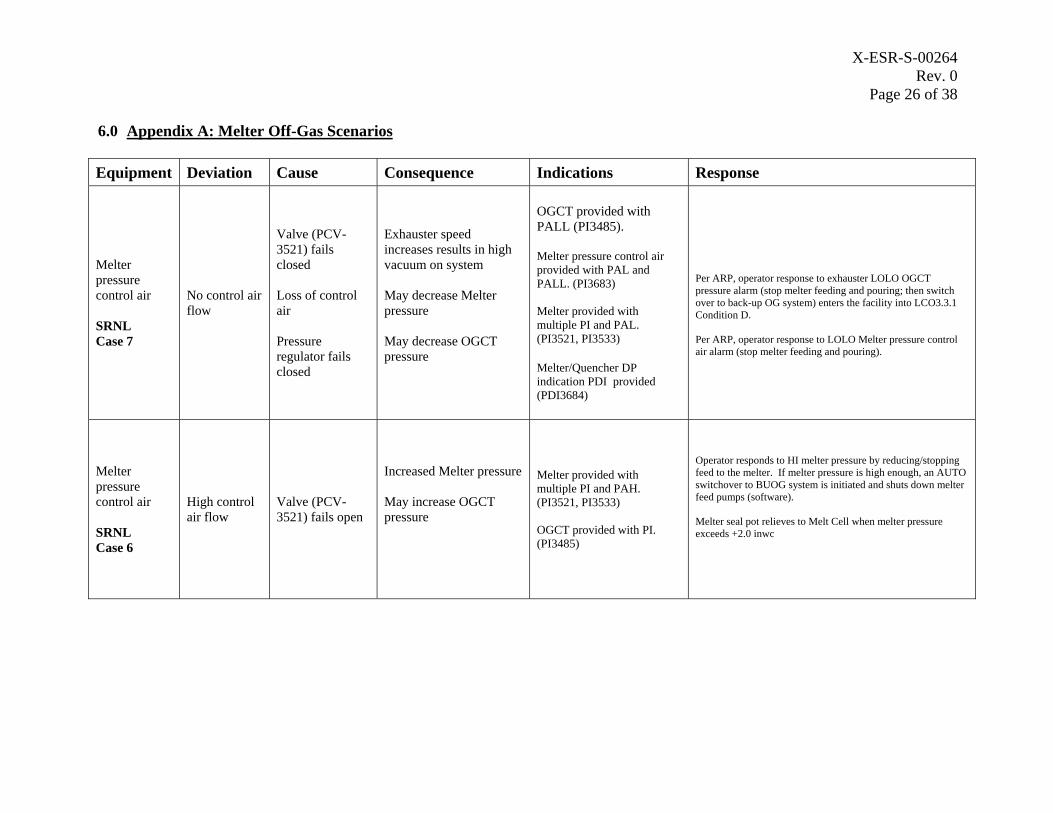
X-ESR-S-00264 Rev. 0
Page 26 of 38
6.0 Appendix A: Melter Off-Gas Scenarios
Equipment Deviation Cause Consequence Indications Response
Melter pressure control air
SRNL Case 7
No control air flow
Valve (PCV-3521) fails closed
Loss of control air
Pressure regulator fails closed
Exhauster speed increases results in high vacuum on system
May decrease Melter pressure
May decrease OGCT pressure
OGCT provided with PALL (PI3485).
Melter pressure control air provided with PAL and PALL. (PI3683)
Melter provided with multiple PI and PAL. (PI3521, PI3533)
Melter/Quencher DP indication PDI provided (PDI3684)
Per ARP, operator response to exhauster LOLO OGCT pressure alarm (stop melter feeding and pouring; then switch over to back-up OG system) enters the facility into LCO3.3.1 Condition D.
Per ARP, operator response to LOLO Melter pressure control air alarm (stop melter feeding and pouring).
Melter pressure control air
SRNL Case 6
High control air flow
Valve (PCV-3521) fails open
Increased Melter pressure
May increase OGCT pressure
Melter provided with multiple PI and PAH. (PI3521, PI3533)
OGCT provided with PI. (PI3485)
Operator responds to HI melter pressure by reducing/stopping feed to the melter. If melter pressure is high enough, an AUTO switchover to BUOG system is initiated and shuts down melter feed pumps (software).
Melter seal pot relieves to Melt Cell when melter pressure exceeds +2.0 inwc
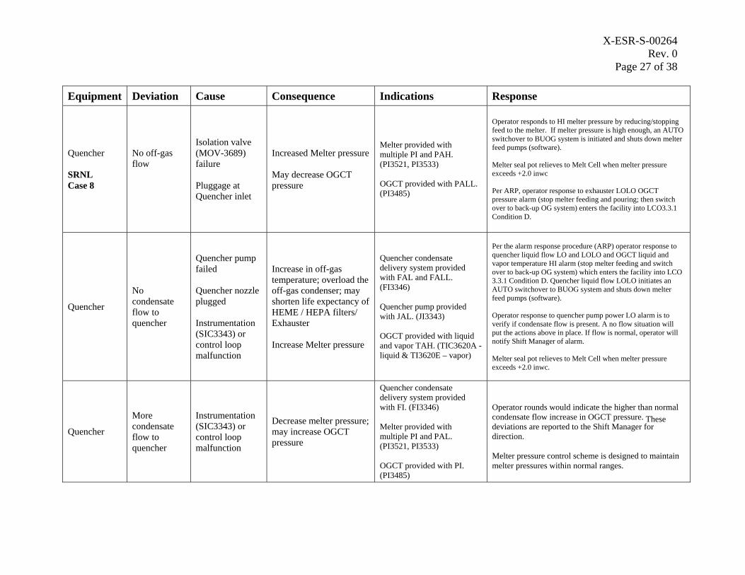
X-ESR-S-00264 Rev. 0
Page 27 of 38
Equipment Deviation Cause Consequence Indications Response
Quencher
SRNL Case 8
No off-gas flow
Isolation valve (MOV-3689) failure
Pluggage at Quencher inlet
Increased Melter pressure
May decrease OGCT pressure
Melter provided with multiple PI and PAH. (PI3521, PI3533)
OGCT provided with PALL. (PI3485)
Operator responds to HI melter pressure by reducing/stopping feed to the melter. If melter pressure is high enough, an AUTO switchover to BUOG system is initiated and shuts down melter feed pumps (software).
Melter seal pot relieves to Melt Cell when melter pressure exceeds +2.0 inwc
Per ARP, operator response to exhauster LOLO OGCT pressure alarm (stop melter feeding and pouring; then switch over to back-up OG system) enters the facility into LCO3.3.1 Condition D.
Quencher
No condensate flow to quencher
Quencher pump failed
Quencher nozzle plugged
Instrumentation (SIC3343) or control loop malfunction
Increase in off-gas temperature; overload the off-gas condenser; may shorten life expectancy of HEME / HEPA filters/ Exhauster
Increase Melter pressure
Quencher condensate delivery system provided with FAL and FALL. (FI3346)
Quencher pump provided with JAL. (JI3343)
OGCT provided with liquid and vapor TAH. (TIC3620A - liquid & TI3620E – vapor)
Per the alarm response procedure (ARP) operator response to quencher liquid flow LO and LOLO and OGCT liquid and vapor temperature HI alarm (stop melter feeding and switch over to back-up OG system) which enters the facility into LCO 3.3.1 Condition D. Quencher liquid flow LOLO initiates an AUTO switchover to BUOG system and shuts down melter feed pumps (software).
Operator response to quencher pump power LO alarm is to verify if condensate flow is present. A no flow situation will put the actions above in place. If flow is normal, operator will notify Shift Manager of alarm.
Melter seal pot relieves to Melt Cell when melter pressure exceeds +2.0 inwc.
Quencher
More condensate flow to
Instrumentation (SIC3343) or control loop
Decrease melter pressure; may increase OGCT
Quencher condensate delivery system provided with FI. (FI3346)
Melter provided with multiple PI and PAL.
Operator rounds would indicate the higher than normal condensate flow increase in OGCT pressure. These deviations are reported to the Shift Manager for direction.
quencher malfunction pressure (PI3521, PI3533)
OGCT provided with PI. (PI3485)
Melter pressure control scheme is designed to maintain melter pressures within normal ranges.
X-ESR-S-00264 Rev. 0
Page 28 of 38
Equipment Deviation Cause Consequence Indications Response
Quencher
Less condensate flow to quencher
Instrument control loop (SIC3343) malfunction
Increase in off-gas temperature; overload the off-gas condenser; may shorten life expectancy of HEME / HEPA filters/ Exhauster
Increase Melter pressure
Quencher condensate delivery system provided with FAL and FALL. (FI3346)
Quencher pump provided with JAL. (JI3343)
OGCT provided with liquid and vapor TAH. (TIC3620A - liquid & TI3620E – vapor)
Per ARP, operator response to quencher liquid flow LO and LOLO and OGCT liquid and vapor temperature HI alarm (stop melter feeding and switch over to back-up OG system) enters the facility into LCO 3.3.1 Condition D. Quencher liquid flow LOLO initiates an AUTO switchover to BUOG system and shuts down melter feed pumps (software).
Operator response to quencher pump power LO alarm is to verify if condensate flow is present. A no flow situation will put the actions above in place. If flow is normal, operator will notify Shift Manager of alarm.
Off-gas Condensate Tank (OGCT)
No Confinement Tank failure
Loss of liquid supplied to Quencher and SAS which could result in high off-gas temperature.
OGCT is provided with LAL, LALL, and TAH. (LI3485 & TI3620E)
Per ARP, operator response to OGCT liquid level LO and LOLO alarm and OGCT vapor temperature HI alarm (stop melter feeding and switch over to back-up OG system) enters the facility into LCO 3.3.1 Condition D.
Off-gas Condensate Tank (OGCT)
High liquid level
OGCT transfer pump failure
Level transmitter failure
Cooling coil leak
Condensate backs up in to the off-gas line from quencher and off-gas line to SAS; Melter over-pressurizes
OGCT provided with LAHH. (LI3485) Cooling coil chilled water provided with RAHH. (RI3626)
Per ARP, operator response to OGCT liquid level HIHI alarm and cooling coil chilled water radiation HIHI alarm (stop melter feeding and switch over to back-up OG system) enters the facility into LCO 3.3.1 Condition D.
Operator responds to HI melter pressure by reducing/stopping feed to the melter. If melter pressure is high enough, an AUTO switchover to BUOG system is initiated and shuts down melter feed pumps (software).
Melter seal pot relieves to Melt Cell when melter pressure exceeds +2.0 inwc.
Off-gas Condensate Tank (OGCT)
High Temperature
Temperature control (TIC3620A) failure
Loss of chilled water
Temperature of liquid rises to Quencher and SAS; increases off-gas temperature, overload the off-gas condenser, may shorten life expectancy of HEME / HEPA filters
OGCT provided with TAH for liquid and vapor temperatures. (TIC3620A - liquid & TI3620E – vapor)
Per ARP, operator response to OGCT liquid and vapor temperature HI alarm (stop melter feeding and switch over to back-up OG system) enters the facility into LCO 3.3.1 Condition D.
X-ESR-S-00264 Rev. 0
Page 29 of 38
Equipment Deviation Cause Consequence Indications Response
Off-gas Condensate Tank (OGCT)
Low liquid level
OGCT transfer pump malfunctions
Level transmitter failure
Quencher or SAS liquid loops leak
Loss of liquid supplied to Quencher and SAS which could result in high off-gas temperature and overload the off-gas condenser, may shorten life expectancy of HEME / HEPA filters
OGCT is provided with LAL, LALL, and TAH. (LI3485 & TI3620E)
Per ARP, operator response to OGCT liquid level LO and LOLO alarm and OGCT vapor temperature HI alarm (stop melter feeding and switch over to back-up OG system) enters the facility into LCO 3.3.1 Condition D.
Isolation valve closed Temperature of liquid
rises to Quencher and OGCT provided with Per ARP, operator response to OGCT liquid and vapor
Chilled water to OGCT
No chilled water flow
Control valve (TIC3620A) fails closed or control loop malfunctions
SAS; increases off-gas temperature, overload the off-gas condenser, may shorten life expectancy of HEME / HEPA filters
TAH for liquid and vapor temperatures. (TIC3620A - liquid & TI3620E – vapor)
temperature HI alarm (stop melter feeding and switch over to back-up OG system) enters the facility into LCO 3.3.1 Condition D.
Control valve OGCT provided with
Chilled water to OGCT
High chilled water flow
(TIC3620A) fails open or control loop
OGCT contents colder than required
liquid and vapor temperature indications. (TIC3620A - liquid &
Operator rounds would indicate the lower than normal OGCT liquid temperature. These deviations are reported to the Shift Manager for direction.
malfunctions TI3620E – vapor)
Chilled water to OGCT
High chilled water temperature
Chilled water system malfunction
Temperature of liquid rises to Quencher and SAS; increases off-gas temperature, overload the off-gas condenser, may shorten life expectancy of HEME / HEPA filters
OGCT provided with TAH for liquid and vapor temperatures. (TIC3620A - liquid & TI3620E – vapor) Chilled water return line provided with TAH. (TI3625)
Per ARP, operator response to OGCT liquid and vapor temperature HI alarm (stop melter feeding and switch over to back-up OG system) enters the facility into LCO 3.3.1 Condition D.
Per ARP, operator response to chilled water return line temperature HI is to ensure that the chill water system is functioning properly and ensure that the OGCT liquid temperature stays below the alarm setpoint.
X-ESR-S-00264 Rev. 0
Page 30 of 38
Equipment Deviation Cause Consequence Indications Response
Chilled water to OGCT
Low chilled water flow
Chilled water line restriction
Control loop malfunctions
Inadequate chilled water supply pressure
Temperature of liquid rises to Quencher and SAS; increases off-gas temperature, overload the off-gas condenser, may shorten life expectancy of HEME / HEPA filters
OGCT provided with TAH for liquid and vapor temperatures. (TIC3620A - liquid & TI3620E – vapor)
Per ARP, operator response to OGCT liquid and vapor temperature HI alarm (stop melter feeding and switch over to back-up OG system) enters the facility into LCO 3.3.1 Condition D.
Steam Atomized Scrubber (SAS)
SRNL Case 11
No off-gas flow
Scrubber plugged
Melter over-pressurizes; vacuum increases downstream of SAS
SAS is provided with PDAH for overall SAS differential pressure (PDI3387) and PDI for SAS 2nd stage discharge pressure (PDI3388).
Per ARP, operator response to HI SAS overall differential pressure alarm is to verify that the OG flow is within range (1100 – 2000 pph), the HEPA DP is within normal range (.31 – 5.0 inwc) and that the exhauster speed is within range (350 – 700 rpm). Shift Manager provides further direction.
Operator responds to HI melter pressure by reducing/stopping feed to the melter.
Melter seal pot relieves to Melt Cell when melter pressure exceeds +2.0 inwc.
Steam Atomized Scrubber (SAS)
No condensate flow
Drain line plugged
Liquid floods SAS and plugs scrubber; melter over-pressurizes; vacuum increases downstream of SAS.
SAS is provided with PDAH for overall SAS differential pressure (PDI3387) and PDI for SAS 2nd stage discharge pressure (PDI3388).
Per ARP, operator response to HI SAS overall differential pressure alarm is to verify that the OG flow is within range (1100 – 2000 pph), the HEPA DP is within normal range (.31 – 5.0 inwc) and that the exhauster speed is within range (350 – 700 rpm). Shift Manager provides further direction.
Operator responds to HI melter pressure by reducing/stopping feed to the melter.
Melter seal pot relieves to Melt Cell when melter pressure exceeds +2.0 inwc.
X-ESR-S-00264 Rev. 0
Page 31 of 38
Equipment Deviation Cause Consequence Indications Response
Steam to SAS No steam flow
Steam supply valve or isolation valve fails closed; loss of steam supply
May increase SAS differential pressure
Scrubbing of off-gas does not occur per design
May shorten life expectancy of HEME / HEPA filters
Steam supply provided with PAL, PALL, FAL, FALL, and FAH. (1st
Stage: PI3590, FI3590) (2nd Stage: PI3595, FI3595)
Per ARP, operator response to OG SAS Stage 1 & 2 steam pressure LO alarm (stop melter feeding and switch over to back-up OG system) enters the facility into LCO 3.3.1 Condition D.
Per ARP, operator response to OG SAS Stage 1 & 2 steam flow LO, LOLO, and HI alarm (switch over to back-up OG system) enters the facility into LCO 3.3.1 Condition D. SAS Stage 1 & 2 steam flow LOLO interlocks melter feed pumps OFF (software interlock).
Steam to SAS High steam flow
Instrument control loop / equipment malfunctions
Bypass isolation valve open
Will affect SAS differential pressure; may shorten life expectancy of HEME / HEPA filters; will increase load to off-gas condenser
Steam supply provided with FAH (1st Stage: FI3590) (2nd Stage: FI3595) and PDAH for overall SAS differential pressure (PDI3388).
Per ARP, operator response to OG SAS Stage 1 & 2 steam flow HI alarm (stop melter feeding and switch over to back-up OG system) enters the facility into LCO 3.3.1 Condition D.
Liquid to SAS
No liquid flow
SAS pump failure
Particles not removed from off-gas which causes:
increase SAS differential pressure; may shorten life expectancy of HEME / HEPA filters; will increase load to off-gas condenser
Liquid supply is provided with FAL (1st Stage: FI3603) (2nd Stage: FI3604). SAS pump provided with JAL (JI3600). PDAH for overall SAS differential pressure (PDI3388).
Per ARP, operator response to OG SAS Stage 1 & 2 liquid flow LO alarm (stop melter feeding and switch over to back-up OG system) enters the facility into LCO 3.3.1 Condition D. SAS Stage 1 & 2 liquid flow LO interlocks melter feed pumps OFF (software interlock).
LO SAS pump power alarm indicates to operator that pump is not running. Feed pumps cannot operate without SAS pump running. (software interlock)
Liquid to SAS
Low liquid flow
SAS nozzle or feed line partially blocked
Instrument (FIC3603) control loop malfunction
Particles not removed from off-gas which causes:
increase SAS differential pressure; may shorten life expectancy of HEME / HEPA filters; will increase load to off-gas condenser
Liquid supply is provided with FAL (1st Stage: FI3603) (2nd Stage: FI3604). PDAH for overall SAS differential pressure (PDI3388).
Per ARP, operator response to OG SAS Stage 1 & 2 liquid flow LO alarm (stop melter feeding and switch over to back-up OG system) enters the facility into LCO 3.3.1 Condition D. SAS Stage 1 & 2 liquid flow LO interlocks melter feed pumps OFF (software interlock).
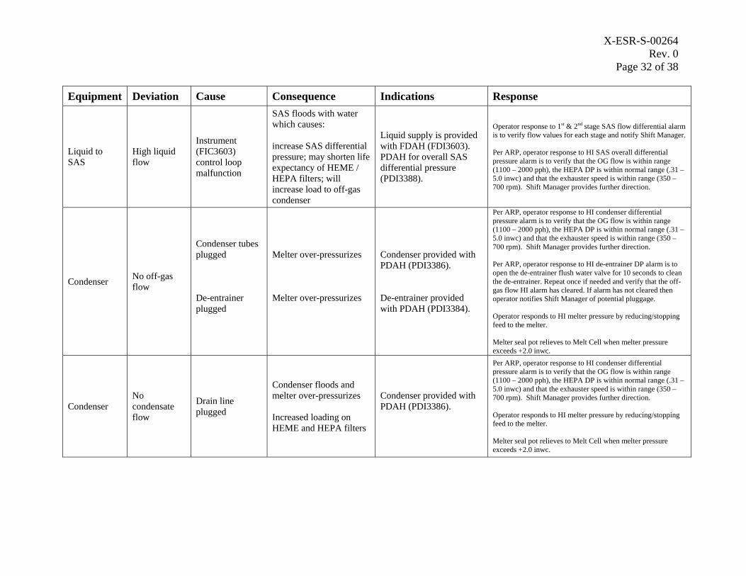
X-ESR-S-00264 Rev. 0
Page 32 of 38
Equipment Deviation Cause Consequence Indications Response
Liquid to SAS
High liquid flow
Instrument (FIC3603) control loop malfunction
SAS floods with water which causes:
increase SAS differential pressure; may shorten life expectancy of HEME / HEPA filters; will increase load to off-gas condenser
Liquid supply is provided with FDAH (FDI3603). PDAH for overall SAS differential pressure (PDI3388).
Operator response to 1st & 2nd stage SAS flow differential alarm is to verify flow values for each stage and notify Shift Manager.
Per ARP, operator response to HI SAS overall differential pressure alarm is to verify that the OG flow is within range (1100 – 2000 pph), the HEPA DP is within normal range (.31 – 5.0 inwc) and that the exhauster speed is within range (350 – 700 rpm). Shift Manager provides further direction.
Per ARP, operator response to HI condenser differential pressure alarm is to verify that the OG flow is within range (1100 – 2000 pph), the HEPA DP is within normal range (.31 –
Condenser tubes plugged Melter over-pressurizes Condenser provided with
5.0 inwc) and that the exhauster speed is within range (350 – 700 rpm). Shift Manager provides further direction.
Condenser No off-gas flow
PDAH (PDI3386). Per ARP, operator response to HI de-entrainer DP alarm is to open the de-entrainer flush water valve for 10 seconds to clean the de-entrainer. Repeat once if needed and verify that the off-gas flow HI alarm has cleared. If alarm has not cleared then
De-entrainer plugged
Melter over-pressurizes De-entrainer provided with PDAH (PDI3384).
operator notifies Shift Manager of potential pluggage.
Operator responds to HI melter pressure by reducing/stopping feed to the melter.
Melter seal pot relieves to Melt Cell when melter pressure exceeds +2.0 inwc.
Condenser No condensate flow
Drain line plugged
Condenser floods and melter over-pressurizes
Increased loading on HEME and HEPA filters
Condenser provided with PDAH (PDI3386).
Per ARP, operator response to HI condenser differential pressure alarm is to verify that the OG flow is within range (1100 – 2000 pph), the HEPA DP is within normal range (.31 – 5.0 inwc) and that the exhauster speed is within range (350 – 700 rpm). Shift Manager provides further direction.
Operator responds to HI melter pressure by reducing/stopping feed to the melter.
Melter seal pot relieves to Melt Cell when melter pressure exceeds +2.0 inwc.
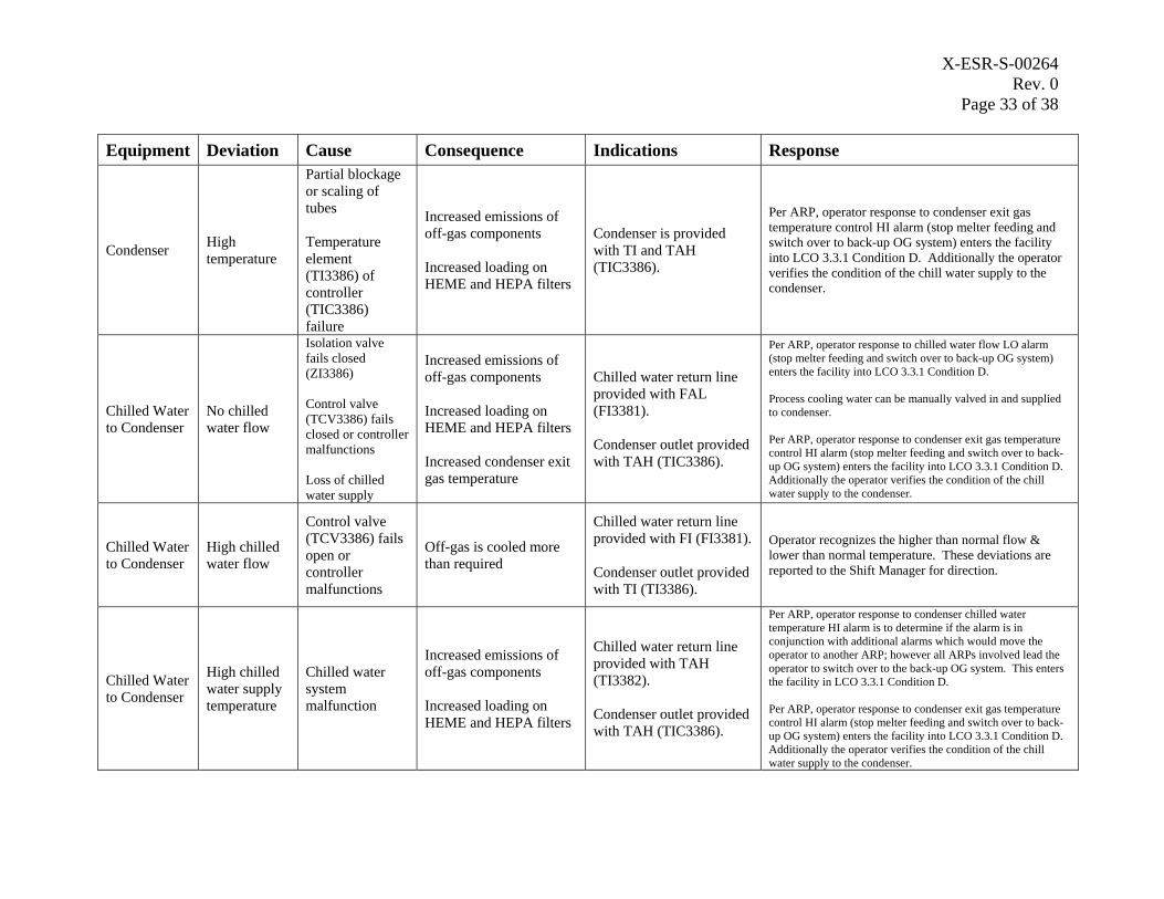
X-ESR-S-00264 Rev. 0
Page 33 of 38
Equipment Deviation Cause Consequence Indications Response
Condenser High temperature
Partial blockage or scaling of tubes
Temperature element (TI3386) of controller (TIC3386) failure
Increased emissions of off-gas components
Increased loading on HEME and HEPA filters
Condenser is provided with TI and TAH (TIC3386).
Per ARP, operator response to condenser exit gas temperature control HI alarm (stop melter feeding and switch over to back-up OG system) enters the facility into LCO 3.3.1 Condition D. Additionally the operator verifies the condition of the chill water supply to the condenser.
Chilled Water to Condenser
No chilled water flow
Isolation valve fails closed (ZI3386)
Control valve (TCV3386) fails closed or controller malfunctions
Loss of chilled water supply
Increased emissions of off-gas components
Increased loading on HEME and HEPA filters
Increased condenser exit gas temperature
Chilled water return line provided with FAL (FI3381).
Condenser outlet provided with TAH (TIC3386).
Per ARP, operator response to chilled water flow LO alarm (stop melter feeding and switch over to back-up OG system) enters the facility into LCO 3.3.1 Condition D.
Process cooling water can be manually valved in and supplied to condenser.
Per ARP, operator response to condenser exit gas temperature control HI alarm (stop melter feeding and switch over to back-up OG system) enters the facility into LCO 3.3.1 Condition D. Additionally the operator verifies the condition of the chill water supply to the condenser.
Chilled Water to Condenser
High chilled water flow
Control valve (TCV3386) fails open or controller malfunctions
Off-gas is cooled more than required
Chilled water return line provided with FI (FI3381).
Condenser outlet provided with TI (TI3386).
Operator recognizes the higher than normal flow & lower than normal temperature. These deviations are reported to the Shift Manager for direction.
Chilled Water to Condenser
High chilled water supply temperature
Chilled water system malfunction
Increased emissions of off-gas components
Increased loading on HEME and HEPA filters
Chilled water return line provided with TAH (TI3382).
Condenser outlet provided with TAH (TIC3386).
Per ARP, operator response to condenser chilled water temperature HI alarm is to determine if the alarm is in conjunction with additional alarms which would move the operator to another ARP; however all ARPs involved lead the operator to switch over to the back-up OG system. This enters the facility in LCO 3.3.1 Condition D.
Per ARP, operator response to condenser exit gas temperature control HI alarm (stop melter feeding and switch over to back-up OG system) enters the facility into LCO 3.3.1 Condition D. Additionally the operator verifies the condition of the chill water supply to the condenser.
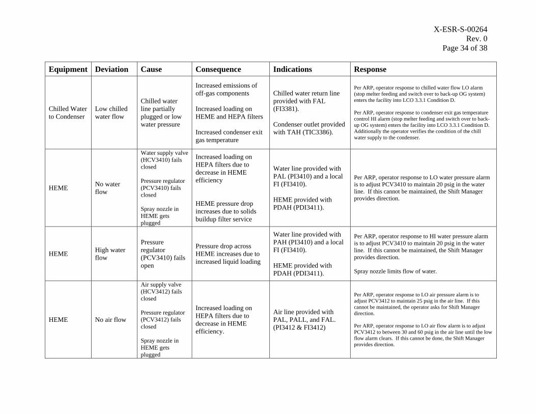
X-ESR-S-00264 Rev. 0
Page 34 of 38
Equipment Deviation Cause Consequence Indications Response
Chilled Water to Condenser
Low chilled water flow
Chilled water line partially plugged or low water pressure
Increased emissions of off-gas components
Increased loading on HEME and HEPA filters
Increased condenser exit gas temperature
Chilled water return line provided with FAL (FI3381).
Condenser outlet provided with TAH (TIC3386).
Per ARP, operator response to chilled water flow LO alarm (stop melter feeding and switch over to back-up OG system) enters the facility into LCO 3.3.1 Condition D.
Per ARP, operator response to condenser exit gas temperature control HI alarm (stop melter feeding and switch over to back-up OG system) enters the facility into LCO 3.3.1 Condition D. Additionally the operator verifies the condition of the chill water supply to the condenser.
HEME No water flow
Water supply valve (HCV3410) fails closed
Pressure regulator (PCV3410) fails closed
Spray nozzle in HEME gets plugged
Increased loading on HEPA filters due to decrease in HEME efficiency
HEME pressure drop increases due to solids buildup filter service
Water line provided with PAL (PI3410) and a local FI (FI3410).
HEME provided with PDAH (PDI3411).
Per ARP, operator response to LO water pressure alarm is to adjust PCV3410 to maintain 20 psig in the water line. If this cannot be maintained, the Shift Manager provides direction.
HEME High water flow
Pressure regulator (PCV3410) fails open
Pressure drop across HEME increases due to increased liquid loading
Water line provided with PAH (PI3410) and a local FI (FI3410).
HEME provided with PDAH (PDI3411).
Per ARP, operator response to HI water pressure alarm is to adjust PCV3410 to maintain 20 psig in the water line. If this cannot be maintained, the Shift Manager provides direction.
Spray nozzle limits flow of water.
HEME No air flow
Air supply valve (HCV3412) fails closed
Pressure regulator (PCV3412) fails closed
Spray nozzle in HEME gets plugged
Increased loading on HEPA filters due to decrease in HEME efficiency.
Air line provided with PAL, PALL, and FAL. (PI3412 & FI3412)
Per ARP, operator response to LO air pressure alarm is to adjust PCV3412 to maintain 25 psig in the air line. If this cannot be maintained, the operator asks for Shift Manager direction.
Per ARP, operator response to LO air flow alarm is to adjust PCV3412 to between 30 and 60 psig in the air line until the low flow alarm clears. If this cannot be done, the Shift Manager provides direction.
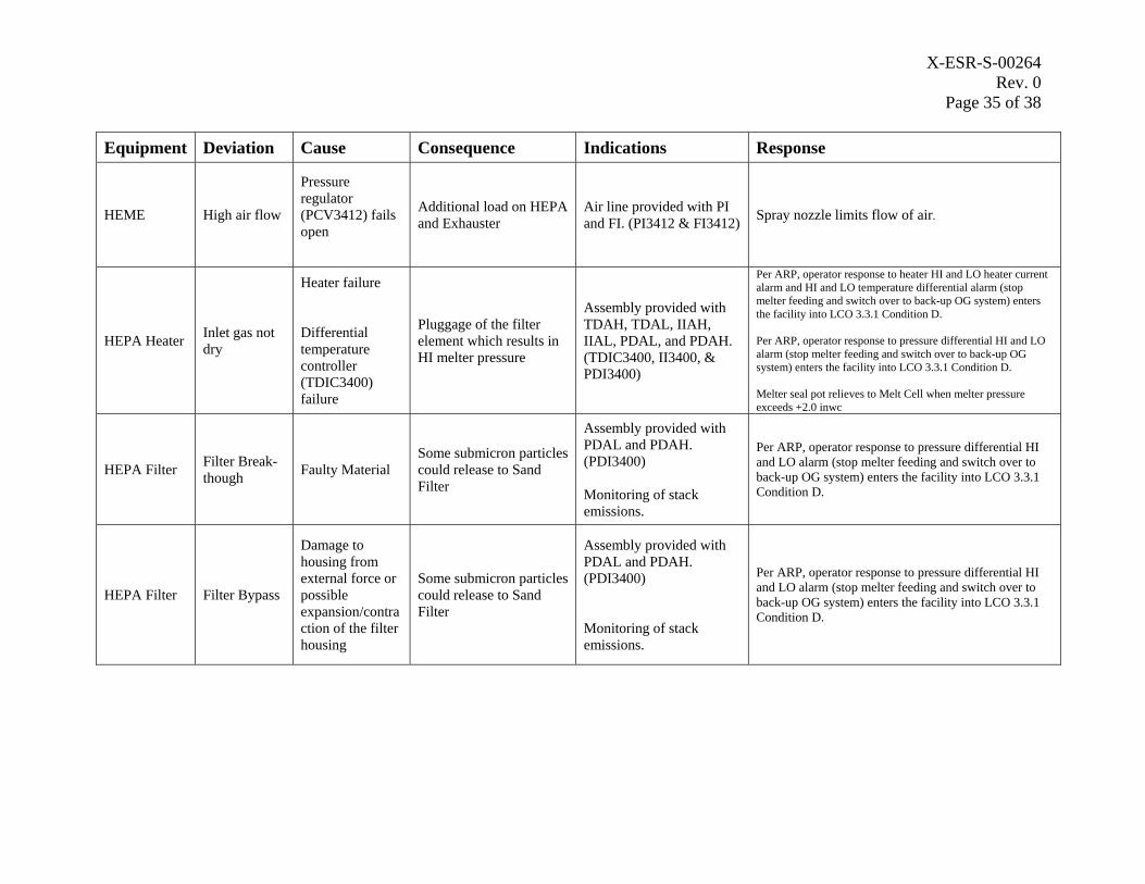
X-ESR-S-00264 Rev. 0
Page 35 of 38
Equipment Deviation Cause Consequence Indications Response
HEME High air flow
Pressure regulator (PCV3412) fails open
Additional load on HEPA and Exhauster
Air line provided with PI and FI. (PI3412 & FI3412) Spray nozzle limits flow of air.
HEPA Heater Inlet gas not dry
Heater failure
Differential temperature controller (TDIC3400) failure
Pluggage of the filter element which results in HI melter pressure
Assembly provided with TDAH, TDAL, IIAH, IIAL, PDAL, and PDAH. (TDIC3400, II3400, & PDI3400)
Per ARP, operator response to heater HI and LO heater current alarm and HI and LO temperature differential alarm (stop melter feeding and switch over to back-up OG system) enters the facility into LCO 3.3.1 Condition D.
Per ARP, operator response to pressure differential HI and LO alarm (stop melter feeding and switch over to back-up OG system) enters the facility into LCO 3.3.1 Condition D.
Melter seal pot relieves to Melt Cell when melter pressure exceeds +2.0 inwc
HEPA Filter Filter Break-though Faulty Material
Some submicron particles could release to Sand Filter
Assembly provided with PDAL and PDAH. (PDI3400)
Monitoring of stack emissions.
Per ARP, operator response to pressure differential HI and LO alarm (stop melter feeding and switch over to back-up OG system) enters the facility into LCO 3.3.1 Condition D.
HEPA Filter Filter Bypass
Damage to housing from external force or possible expansion/contra ction of the filter housing
Some submicron particles could release to Sand Filter
Assembly provided with PDAL and PDAH. (PDI3400)
Monitoring of stack emissions.
Per ARP, operator response to pressure differential HI and LO alarm (stop melter feeding and switch over to back-up OG system) enters the facility into LCO 3.3.1 Condition D.
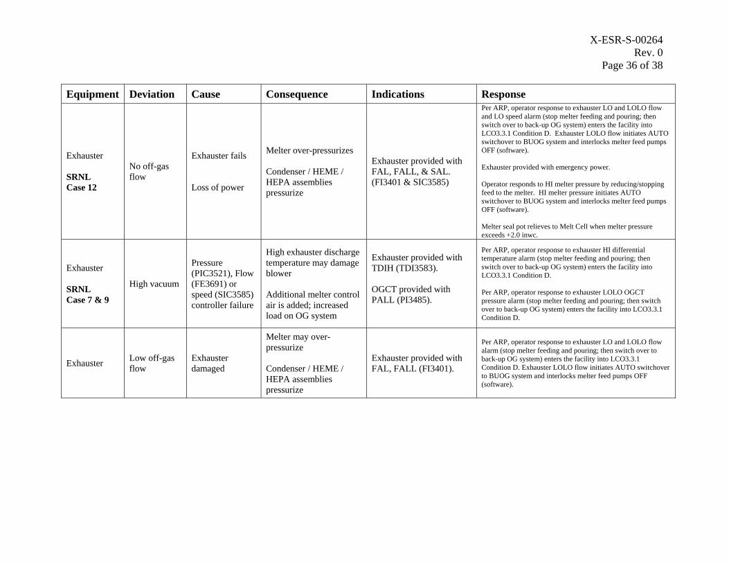
X-ESR-S-00264 Rev. 0
Page 36 of 38
Equipment Deviation Cause Consequence Indications Response
Exhauster
SRNL Case 12
No off-gas flow
Exhauster fails
Loss of power
Melter over-pressurizes
Condenser / HEME / HEPA assemblies pressurize
Exhauster provided with FAL, FALL, & SAL. (FI3401 & SIC3585)
Per ARP, operator response to exhauster LO and LOLO flow and LO speed alarm (stop melter feeding and pouring; then switch over to back-up OG system) enters the facility into LCO3.3.1 Condition D. Exhauster LOLO flow initiates AUTO switchover to BUOG system and interlocks melter feed pumps OFF (software).
Exhauster provided with emergency power.
Operator responds to HI melter pressure by reducing/stopping feed to the melter. HI melter pressure initiates AUTO switchover to BUOG system and interlocks melter feed pumps OFF (software).
Melter seal pot relieves to Melt Cell when melter pressure exceeds +2.0 inwc.
Exhauster
SRNL Case 7 & 9
High vacuum
Pressure (PIC3521), Flow (FE3691) or speed (SIC3585) controller failure
High exhauster discharge temperature may damage blower
Additional melter control air is added; increased load on OG system
Exhauster provided with TDIH (TDI3583).
OGCT provided with PALL (PI3485).
Per ARP, operator response to exhauster HI differential temperature alarm (stop melter feeding and pouring; then switch over to back-up OG system) enters the facility into LCO3.3.1 Condition D.
Per ARP, operator response to exhauster LOLO OGCT pressure alarm (stop melter feeding and pouring; then switch over to back-up OG system) enters the facility into LCO3.3.1 Condition D.
Exhauster Low off-gas flow
Exhauster damaged
Melter may over-pressurize
Condenser / HEME / HEPA assemblies pressurize
Exhauster provided with FAL, FALL (FI3401).
Per ARP, operator response to exhauster LO and LOLO flow alarm (stop melter feeding and pouring; then switch over to back-up OG system) enters the facility into LCO3.3.1 Condition D. Exhauster LOLO flow initiates AUTO switchover to BUOG system and interlocks melter feed pumps OFF (software).
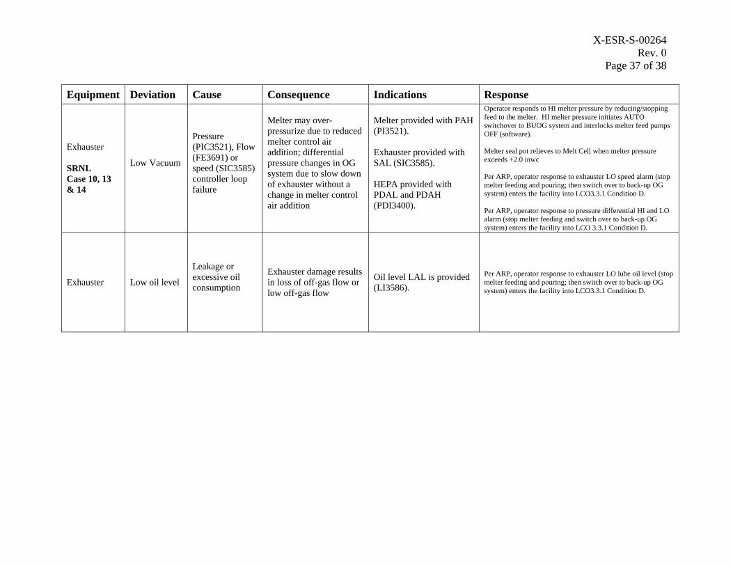
X-ESR-S-00264 Rev. 0
Page 37 of 38
Equipment Deviation Cause Consequence Indications Response
Exhauster
SRNL Case 10, 13 & 14
Low Vacuum
Pressure (PIC3521), Flow (FE3691) or speed (SIC3585) controller loop failure
Melter may over-pressurize due to reduced melter control air addition; differential pressure changes in OG system due to slow down of exhauster without a change in melter control air addition
Melter provided with PAH (PI3521).
Exhauster provided with SAL (SIC3585).
HEPA provided with PDAL and PDAH (PDI3400).
Operator responds to HI melter pressure by reducing/stopping feed to the melter. HI melter pressure initiates AUTO switchover to BUOG system and interlocks melter feed pumps OFF (software).
Melter seal pot relieves to Melt Cell when melter pressure exceeds +2.0 inwc
Per ARP, operator response to exhauster LO speed alarm (stop melter feeding and pouring; then switch over to back-up OG system) enters the facility into LCO3.3.1 Condition D.
Per ARP, operator response to pressure differential HI and LO alarm (stop melter feeding and switch over to back-up OG system) enters the facility into LCO 3.3.1 Condition D.
Exhauster Low oil level
Leakage or excessive oil consumption
Exhauster damage results in loss of off-gas flow or low off-gas flow
Oil level LAL is provided (LI3586).
Per ARP, operator response to exhauster LO lube oil level (stop melter feeding and pouring; then switch over to back-up OG system) enters the facility into LCO3.3.1 Condition D.
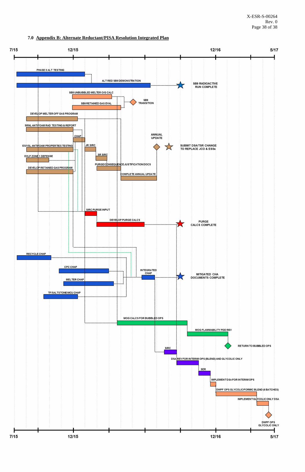
X-ESR-S-00264 Rev. 0
Page 38 of 38
7.0 Appendix B: Alternate Reductant/PISA Resolution Integrated Plan