warrior field operations manual v7 utilities... · fig: 13.13 open with notepad the cbl.let file...
TRANSCRIPT

280Warrior Software Version 7.0 Standard Cased Hole
13 Utilities
The Utilities icon in the Warrior Program Group allows access to several programs, some with
general, and some with more specific, applications.
FIG: 13.1 Warrior Program Group
The warrior Utilities has six modules:
1) Data Export 2) Interpretation Tools 3) Data Import 4) Depth Correction 5) Data Management 6) Setup Tools
Clicking on the icon Utilities gives a menu list as shown below.
Section
13

281 Warrior Software Version 7.0 Standard Cased Hole
FIG: 13.2 Warrior Utilities
13.1 Data Export
13.1.1 Export to LAS Format
FIG: 13.3 Export LAS Format

282Warrior Software Version 7.0 Standard Cased Hole
FIG: 13.4 Select Database, Data Set, Heading
FIG: 13.5 Set LAS Outputs

283 Warrior Software Version 7.0 Standard Cased Hole
FIG: 13.6 Select curves Y/N and Start
FIG: 13.7 Processing
VIDEO: 13.1 Export LAS

284Warrior Software Version 7.0 Standard Cased Hole
13.1.2 Export to LIS Format
FIG: 13.8 Export to LIS Format
FIG: 13.9 Select DATA to Built the LIS

285 Warrior Software Version 7.0 Standard Cased Hole
FIG: 13.10 Add a Heading to export list
FIG: 13.11 Select Template (*.LET)

286Warrior Software Version 7.0 Standard Cased Hole
13.1.2.1 LET Files LET files are used to define the output data for Warrior LIS Exporting (LIS Export Template). This needs to be a sequentially numbered set of outputs. All outputs from a log pass do not have to be listed, but only those listed will be output into the LIS file
13.1.2.1.1 First Item The first item in the list must be number [0]. This defines the title and frame spacing or output rate. The title is used for information only. The Frame Spacing is followed by one to three parameters. The first parameter is the out rate in inches if the rate is in feet. The second parameter is the output rate in Millimeters if the rate is in meters. The third parameter is the output rate in seconds if it is a time drive log. Example: [0]
Title=CBL Export FrameSpacing=3,77,.1
13.1.2.1.2 Data Items Each data item output must be listed with an InputName that is shown as the mnemonic used in the Warrior database. OutputName is optional, but should be used if the input name is longer than 4 characters, otherwise the input name will be truncated to the first 4 characters. LIS Standard is no mnemonic longer than 4 characters. The SampleSpacing is optional. This is used if a rate different than the FrameSpacing is required. It has the same three parameters as the FrameSpacing listed above.Example: [2]
InputName=CCL OutputName=CCL SampleSpacing=1.2
13.1.2.1.3 Last Item - Depth The last data item should be DEPTH. Note that since Depth is 5 characters, it will automatically be truncated to DEPT, but it is standard to show the output name as DEPT. Example:
[8] InputName=DEPTH OutputName=DEPT
FIG: 13.12 Select Log Export Templates

287 Warrior Software Version 7.0 Standard Cased Hole
FIG: 13.13 Open with Notepad the CBL.let file
FIG: 13.14 Setup the Export File

288Warrior Software Version 7.0 Standard Cased Hole
FIG: 13.15 Build Export File List
FIG: 13.16 File Base Name
VIDEO: 13.2 Export to LIS

289 Warrior Software Version 7.0 Standard Cased Hole
13.1.3 Export to ODBC compatible Database This program will export data for Excel, Access, FoxPro and other ODBC compatible databases. The limit for exporting data is 255 data points per sample. A normal curve is one data point but a waveform will be many more points for each sample. You will see a message in the progress window that the column count has exceeded if you exceed that amount.
FIG: 13.17 Export to ODBC Compatible Database

290Warrior Software Version 7.0 Standard Cased Hole
13.1.4 Extract Pass (es) to New Database.
FIG: 13.18 Extract Pass(es) to New Database
FIG: 13.19 Select Database
291 Warrior Software Version 7.0 Standard Cased Hole
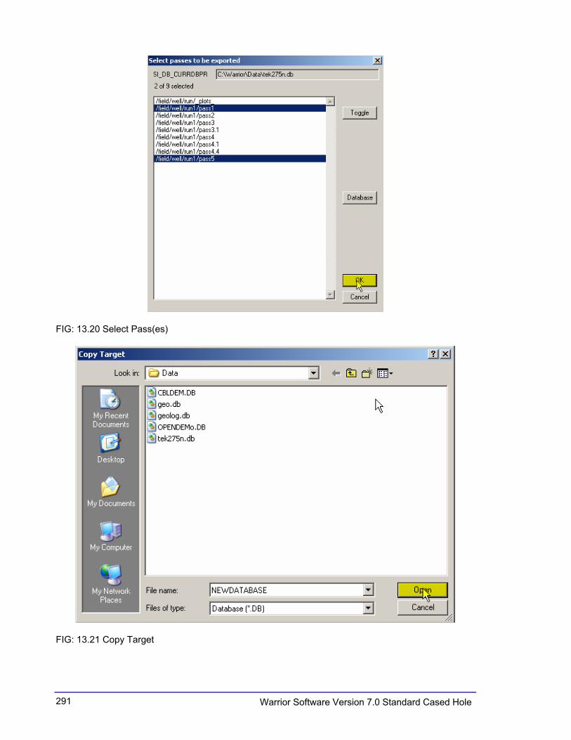
FIG: 13.20 Select Pass(es)
FIG: 13.21 Copy Target

292Warrior Software Version 7.0 Standard Cased Hole
FIG: 13.22 Packing
FIG: 13.23 Check the Database Target
FIG: 13.24 View Passes in the Target
VIDEO: 13.3 Extract Pass(es)

293 Warrior Software Version 7.0 Standard Cased Hole
13.2 Interpretation Tools
13.2.1 Mathpack See section 15
FIG: 13.25 Math Pack
13.2.2 XY Plot A cross plot will consist of one or more curves. Each curve will be created by plotting one database item plotted against depth or time or from one database item plotted against another database item.
FIG: 13.26 XY Plot
294Warrior Software Version 7.0 Standard Cased Hole
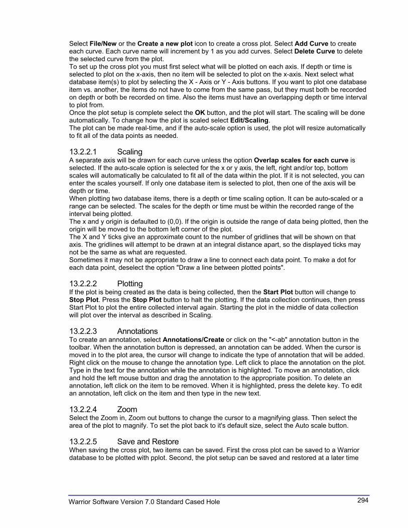
Select File/New or the Create a new plot icon to create a cross plot. Select Add Curve to create each curve. Each curve name will increment by 1 as you add curves. Select Delete Curve to delete the selected curve from the plot. To set up the cross plot you must first select what will be plotted on each axis. If depth or time is selected to plot on the x-axis, then no item will be selected to plot on the x-axis. Next select what database item(s) to plot by selecting the X - Axis or Y - Axis buttons. If you want to plot one database item vs. another, the items do not have to come from the same pass, but they must both be recorded on depth or both be recorded on time. Also the items must have an overlapping depth or time interval to plot from. Once the plot setup is complete select the OK button, and the plot will start. The scaling will be done automatically. To change how the plot is scaled select Edit/Scaling.The plot can be made real-time, and if the auto-scale option is used, the plot will resize automatically to fit all of the data points as needed.
13.2.2.1 Scaling A separate axis will be drawn for each curve unless the option Overlap scales for each curve isselected. If the auto-scale option is selected for the x or y axis, the left, right and/or top, bottom scales will automatically be calculated to fit all of the data within the plot. If it is not selected, you can enter the scales yourself. If only one database item is selected to plot, then one of the axis will be depth or time. When plotting two database items, there is a depth or time scaling option. It can be auto-scaled or a range can be selected. The scales for the depth or time must be within the recorded range of the interval being plotted. The x and y origin is defaulted to (0,0). If the origin is outside the range of data being plotted, then the origin will be moved to the bottom left corner of the plot. The X and Y ticks give an approximate count to the number of gridlines that will be shown on that axis. The gridlines will attempt to be drawn at an integral distance apart, so the displayed ticks may not be the same as what are requested. Sometimes it may not be appropriate to draw a line to connect each data point. To make a dot for each data point, deselect the option "Draw a line between plotted points".
13.2.2.2 Plotting If the plot is being created as the data is being collected, then the Start Plot button will change to Stop Plot. Press the Stop Plot button to halt the plotting. If the data collection continues, then press Start Plot to plot the entire collected interval again. Starting the plot in the middle of data collection will plot over the interval as described in Scaling.
13.2.2.3 Annotations To create an annotation, select Annotations/Create or click on the "<-ab" annotation button in the toolbar. When the annotation button is depressed, an annotation can be added. When the cursor is moved in to the plot area, the cursor will change to indicate the type of annotation that will be added. Right click on the mouse to change the annotation type. Left click to place the annotation on the plot. Type in the text for the annotation while the annotation is highlighted. To move an annotation, click and hold the left mouse button and drag the annotation to the appropriate position. To delete an annotation, left click on the item to be removed. When it is highlighted, press the delete key. To edit an annotation, left click on the item and then type in the new text.
13.2.2.4 Zoom Select the Zoom in, Zoom out buttons to change the cursor to a magnifying glass. Then select the area of the plot to magnify. To set the plot back to it's default size, select the Auto scale button.
13.2.2.5 Save and Restore When saving the cross plot, two items can be saved. First the cross plot can be saved to a Warrior database to be plotted with pplot. Second, the plot setup can be saved and restored at a later time
295 Warrior Software Version 7.0 Standard Cased Hole
with the cross plot program. Saving the setup does not save the plot itself - it only saves the curve(s) being plotted and the setup used to create the plot. The plot heading is only seen when the plot is printed. It can accept multiple lines by hitting the enter key at the end of each line.
FIG: 13.27 Plot setup
FIG: 13.28 Setup Axis

296Warrior Software Version 7.0 Standard Cased Hole
FIG: 13.29 Select database and Curve
FIG: 13.30 XYPLOT

297 Warrior Software Version 7.0 Standard Cased Hole
FIG: 13.31 XYPlot Scaling
FIG: 13.32 Edit Curve setting

298Warrior Software Version 7.0 Standard Cased Hole
FIG: 13.33 XYPlot with new setting
FIG: 13.34 XYPlot Change Axis

299 Warrior Software Version 7.0 Standard Cased Hole
FIG: 13.35 XYPlot
FIG: 13.36 XYPlot setup (X/Y) for two curves

300Warrior Software Version 7.0 Standard Cased Hole
FIG: 13.37 XYPlot
FIG: 13.38 XYPlot new setting zoom
301 Warrior Software Version 7.0 Standard Cased Hole
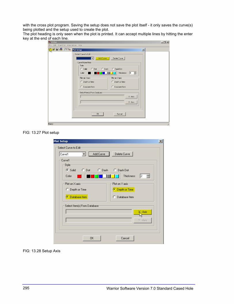
FIG: 13.39 XYPlot Two curves in the same chart
VIDEO: 13.3 XY PLOT

302Warrior Software Version 7.0 Standard Cased Hole
13.2.3 Tracer Interpretation
FIG: 13.40 Tracer Interpretation

303 Warrior Software Version 7.0 Standard Cased Hole
13.2.4 Create Differential Curve
FIG: 13.41 Create Differential Curve
FIG: 13.42 Create Differential curves. (DIFFCCL)
FIG: 13.43 Processing

304Warrior Software Version 7.0 Standard Cased Hole
13.2.5 Create Total Dissolved Solids Curve
FIG: 13.44 Create Total Dissolved Solids Curve
13.2.6 Calculate Borehole Volume from Caliper
FIG: 13.45 Calculate Borehole Volume from Caliper
305 Warrior Software Version 7.0 Standard Cased Hole
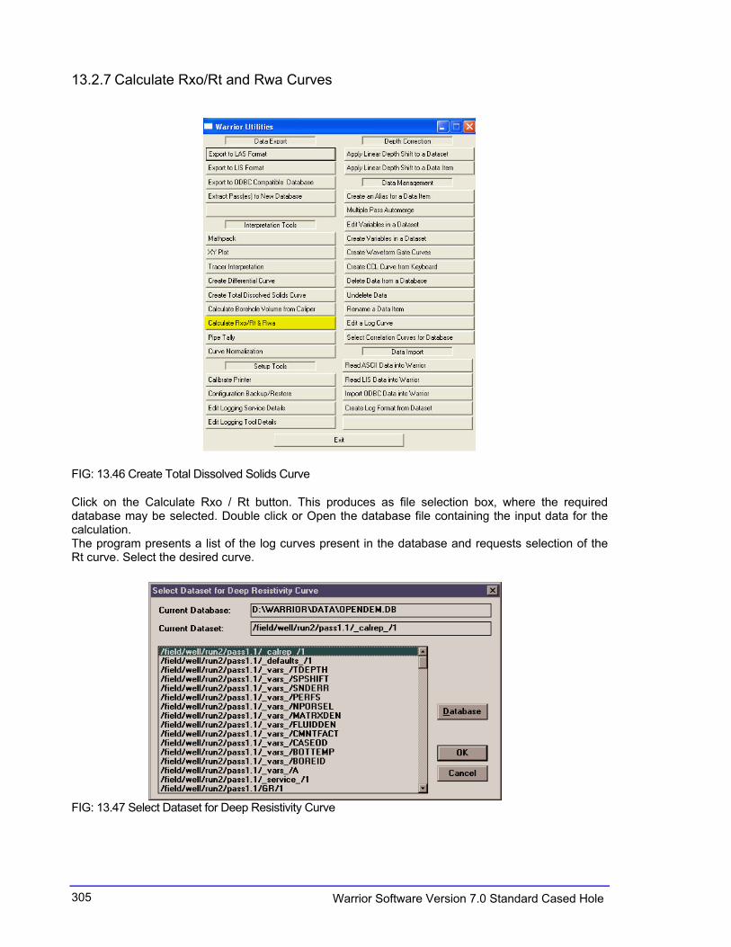
13.2.7 Calculate Rxo/Rt and Rwa Curves
FIG: 13.46 Create Total Dissolved Solids Curve
Click on the Calculate Rxo / Rt button. This produces as file selection box, where the required database may be selected. Double click or Open the database file containing the input data for the calculation. The program presents a list of the log curves present in the database and requests selection of the Rt curve. Select the desired curve.
FIG: 13.47 Select Dataset for Deep Resistivity Curve
306Warrior Software Version 7.0 Standard Cased Hole
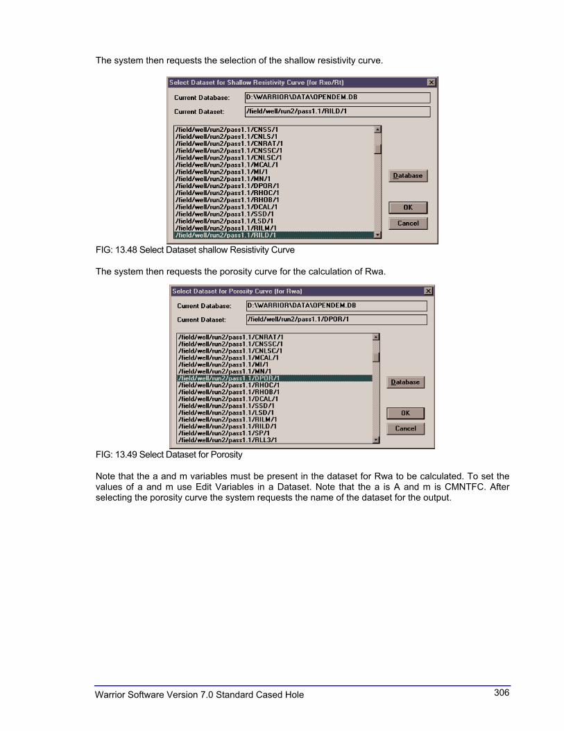
The system then requests the selection of the shallow resistivity curve.
FIG: 13.48 Select Dataset shallow Resistivity Curve
The system then requests the porosity curve for the calculation of Rwa.
FIG: 13.49 Select Dataset for Porosity
Note that the a and m variables must be present in the dataset for Rwa to be calculated. To set the values of a and m use Edit Variables in a Dataset. Note that the a is A and m is CMNTFC. After selecting the porosity curve the system requests the name of the dataset for the output.
307 Warrior Software Version 7.0 Standard Cased Hole
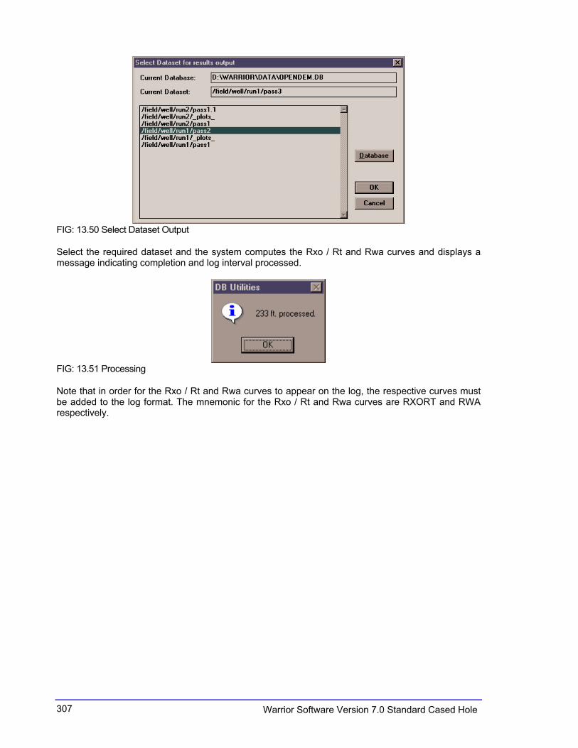
FIG: 13.50 Select Dataset Output
Select the required dataset and the system computes the Rxo / Rt and Rwa curves and displays a message indicating completion and log interval processed.
FIG: 13.51 Processing
Note that in order for the Rxo / Rt and Rwa curves to appear on the log, the respective curves must be added to the log format. The mnemonic for the Rxo / Rt and Rwa curves are RXORT and RWA respectively.
308Warrior Software Version 7.0 Standard Cased Hole
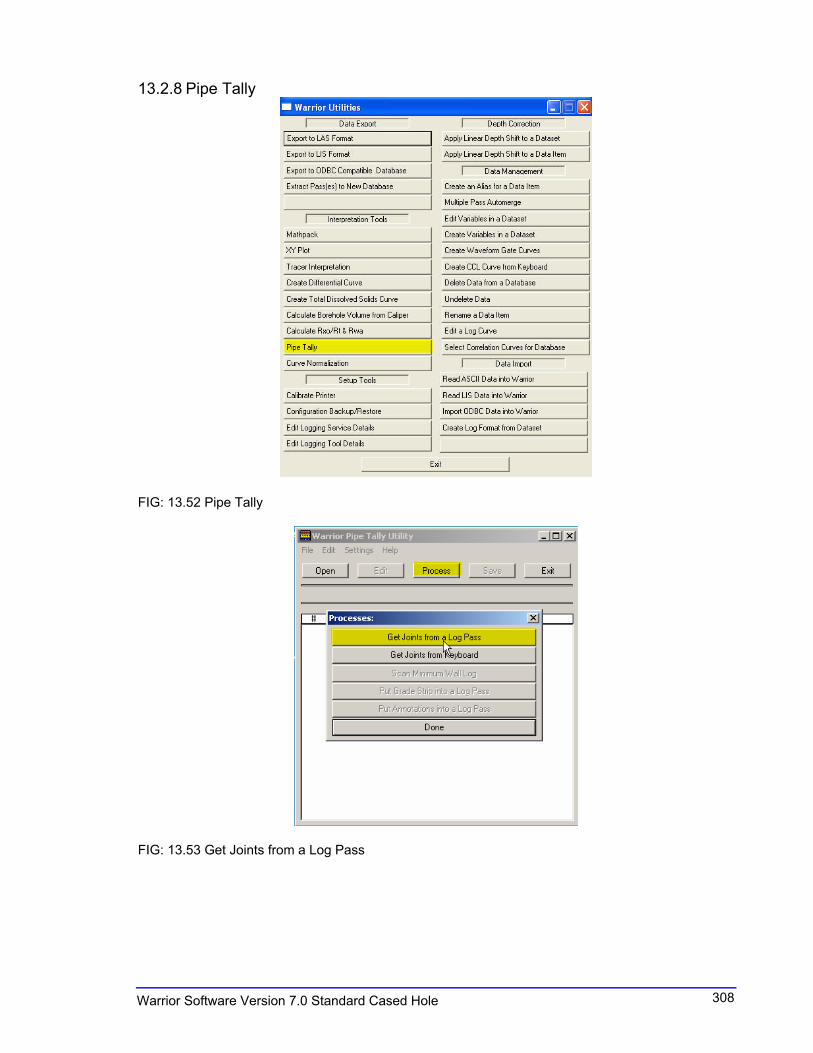
13.2.8 Pipe Tally
FIG: 13.52 Pipe Tally
FIG: 13.53 Get Joints from a Log Pass
309 Warrior Software Version 7.0 Standard Cased Hole
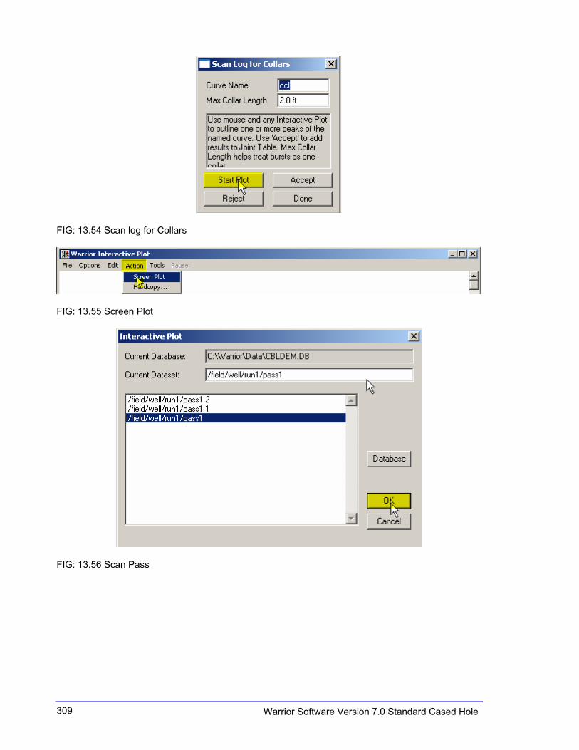
FIG: 13.54 Scan log for Collars
FIG: 13.55 Screen Plot
FIG: 13.56 Scan Pass

310Warrior Software Version 7.0 Standard Cased Hole
FIG: 13.57 Plot Pass and select area
FIG: 13.58 Accept

311 Warrior Software Version 7.0 Standard Cased Hole
FIG: 13.59 Done
FIG: 13.60 Done
FIG: 13.61 Results
VIDEO: 13.4 Pipe Tally

312Warrior Software Version 7.0 Standard Cased Hole
13.2.9 Curve Normalization This program will cross plot two curves over a chosen interval. Then it calculates the gain and offset required to apply to the second curve (Curve to be normalized) to make it overlay the first (Reference curve). Select the reference curve, then the curve to be normalized. Interactive plot should start with the reference log pass. You should be able to plot the curve to be normalized on that same pass - look in the progress window to see the name (alias) that was created for the normalized curve. From interactive plot you can drag a rectangle over the interval to choose the depth range for normalization. Once that is done, and then selects MakeXY. If you are satisfied with the data points in the XY plot, then select Normalize. Interactive plot will start again, but this time with the pass from the normalized curve. If you look in the progress window, another curve will have been created in the Normalized pass. That curve will be what the curve looked like prior to the normalization. The name should be the same as the normalized curve except preceded by a ‘.’, and the normalized curve will have the original name.
FIG: 13.62 Curve Normalization
13.3 Data Import
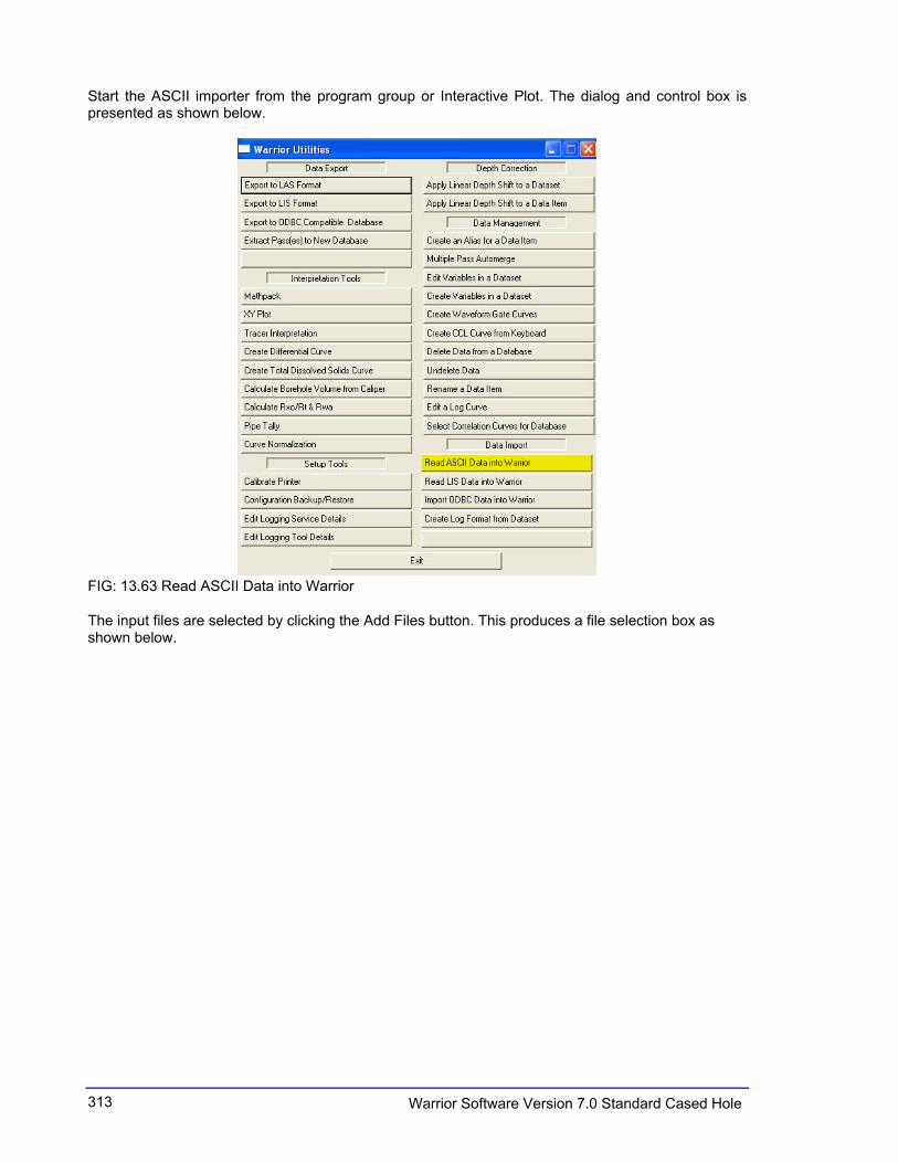
13.3.1 Read ASCII Data into the Warrior (LAS) In the Warrior System group, choose the Utilities icon. (Double-click the icon, or use the arrow key to move the selection cursor to the icon and hit Enter.) The window shown below appears. The ASCII Importer reads data from existing ASCII file(s) and writes the data to one or more Warrior well log database files.
313 Warrior Software Version 7.0 Standard Cased Hole
Start the ASCII importer from the program group or Interactive Plot. The dialog and control box is presented as shown below.
FIG: 13.63 Read ASCII Data into Warrior
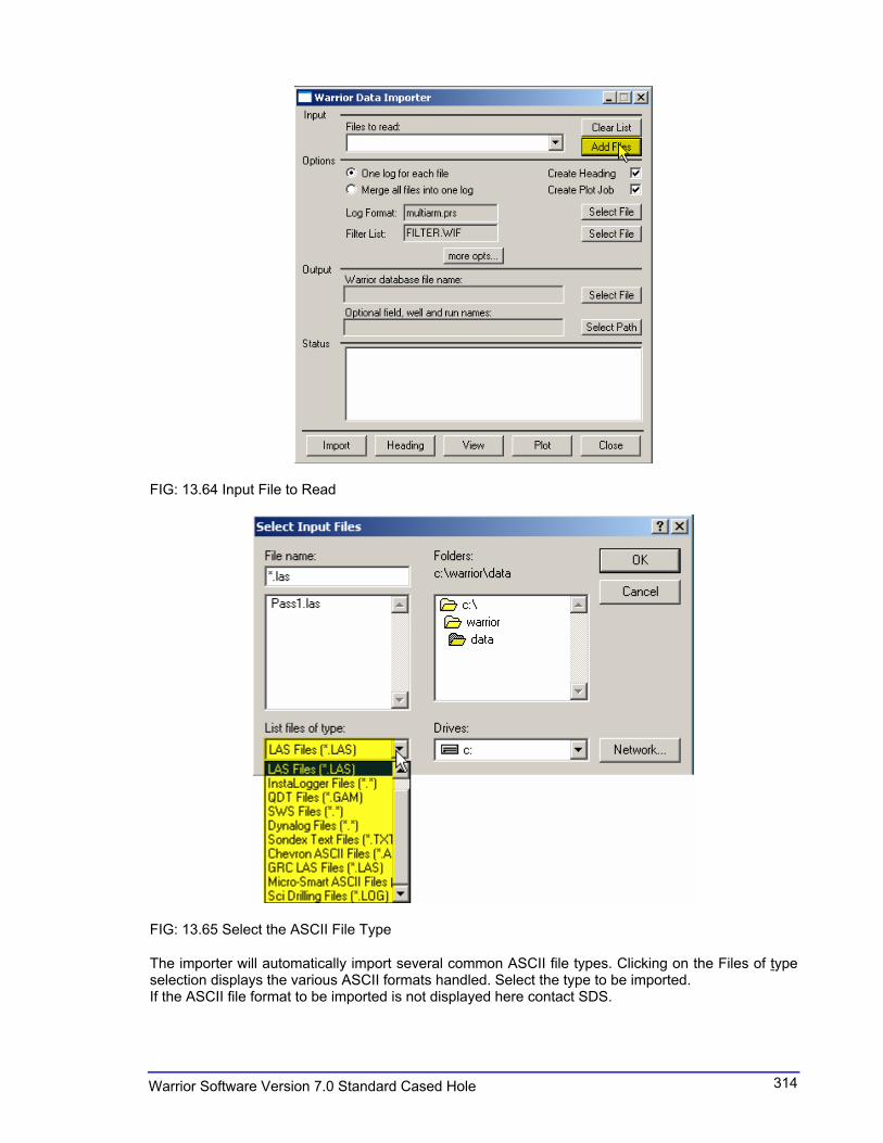
The input files are selected by clicking the Add Files button. This produces a file selection box as shown below.
314Warrior Software Version 7.0 Standard Cased Hole
FIG: 13.64 Input File to Read
FIG: 13.65 Select the ASCII File Type
The importer will automatically import several common ASCII file types. Clicking on the Files of typeselection displays the various ASCII formats handled. Select the type to be imported. If the ASCII file format to be imported is not displayed here contact SDS.

315 Warrior Software Version 7.0 Standard Cased Hole
Select the required ASCII files in the normal way and click Open. The selected files may be viewed by clicking the button in the Files to read: field. The selected files may be cleared by clicking the Clear List button. In Options Clicking the One log for each file radio button generates a warrior log pass for each ASCII file selected. Clicking the Merge all files into one log button merges all the selected ASCII files into one log pass. If the ASCII files contain curves of the same name, the importer will automatically add a numerical subscript to the duplicate curves according to the order they appear in the Files to read: list. The default presentation file for the new log pass is entered in the Log Format field by clicking the corresponding Select File button. The filter list file has the default extension .wif. It may be selected by clicking the corresponding Select File button. Checking the Create Heading selection causes the importer to create a log heading file based on any available information from the ASCII input file(s). If no information is available it will create a blank heading in the new database. Checking the Create Plot Job selection causes the importer to create a default plot job based on the log heading (if any) and the imported log passes.
FIG: 13.66 Select File

316Warrior Software Version 7.0 Standard Cased Hole
FIG: 13.67 Setup Warrior data Importer
If required the curves may be filtered during the import process. An ASCII text file must be created in the \warrior\bin directory and consist of a list of filter definitions similar to those used in the tools.ini file to define default filters
FIG: 13.68 Start to select the curves

317 Warrior Software Version 7.0 Standard Cased Hole
FIG: 13.69 Reading the ASCII and convert to DB
The status window displays a log of the importing operations. Having made the various selections and chosen the required options the importer may be run by clicking the Import button. The importer will read the selected ASCII files and display the status. Clicking the Heading button starts the Heading Editor program and displays the heading generated by the import process. If Create Heading was not selected a blank heading will be presented. Clicking the View button starts the Interactive Plot program for screen display of the results of the import process. Clicking the Plot button starts the Plot Job Editor program with the plot job generated during the import process (if any). If Create Plot Job was not checked a blank plot job is presented. The Close button closes the Importer program.
VIDEO: 13.5 Read ASCII
318Warrior Software Version 7.0 Standard Cased Hole
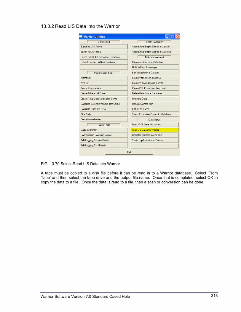
13.3.2 Read LIS Data into the Warrior
FIG: 13.70 Select Read LIS Data into Warrior
A tape must be copied to a disk file before it can be read in to a Warrior database. Select ‘From Tape’ and then select the tape drive and the output file name. Once that is completed, select OK to copy the data to a file. Once the data is read to a file, then a scan or conversion can be done.

319 Warrior Software Version 7.0 Standard Cased Hole
FIG: 13.71 Select LIS file
After the LIS file has been selected, choose one of the LIS file types. If you are not sure what the file type is then select Unknown. This will loop through all of the LIS file types until it can read the file without an error.
FIG: 13.72 CBL.NIT File
320Warrior Software Version 7.0 Standard Cased Hole
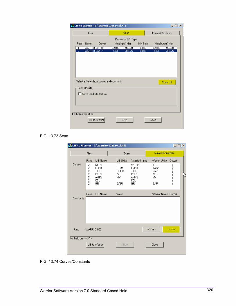
FIG: 13.73 Scan
FIG: 13.74 Curves/Constants

321 Warrior Software Version 7.0 Standard Cased Hole
FIG: 13.75 Convert List to Warrior
The destination database file name does not have to exist, but the specific run given for the destination cannot exist. For any LIS passes greater than the first pass, the LIS pass number will be appended to the output Warrior database pass name to create a unique Warrior name for each pass. If a header is requested, then the heading information will be filled out based on the type of heading chosen. The heading that is chosen will affect the list of available heading names shown when editing constants from the Curves/Constants dialog. The heading that is created will go to /[field]/[well]/[run]/_plots_/_headings_/1. Only one heading is allowed per /[field]/[well]/[run]/. Therefore, if a database is created from a LIS file with multiple passes, only the heading information from the first pass will be used to create the heading

322Warrior Software Version 7.0 Standard Cased Hole
FIG: 13.76 Output
FIG: 13.77 Header not Output Curves
FIG: 13.78 Setup Output Details (see CBL.LET file Section 13.1.2.1)
323 Warrior Software Version 7.0 Standard Cased Hole
More Information Required for Waveform Data The top line of the dialog contains the pass number and name from the LIS tape. The start time for the waveform is the number of microseconds that elapsed prior to the beginning of recording the waveform. The waveform sample rate is the total sample interval (in microseconds) divided by the total number of samples taken. The minimum and maximum recordable waveform values are required for scaling the waveform plot properly. For example, a 13 bit-sampling device may have a range of values from –2048 to +2047.
VIDEO: 13.6 Read LIS
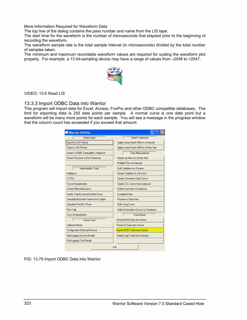
13.3.3 Import ODBC Data into Warrior This program will import data for Excel, Access, FoxPro and other ODBC compatible databases. The limit for exporting data is 255 data points per sample. A normal curve is one data point but a waveform will be many more points for each sample. You will see a message in the progress window that the column count has exceeded if you exceed that amount.
FIG: 13.79 Import ODBC Data Into Warrior

324Warrior Software Version 7.0 Standard Cased Hole
13.3.4 Create Log format from Dataset
FIG: 13.80 Create Format from Dataset
13.4 Depth Correction
13.4.1 Apply linear Depth Shift to the a Dataset This feature is intended to provide a rapid tie-in capability by applying a linear depth shift to a Dataset. Once a section of log has been made and is displayed on the screen, select Depth Shift from the Action menu.

325 Warrior Software Version 7.0 Standard Cased Hole
FIG: 13.81 Apply Linear Depth Shift to a Dataset
Clicking on this button brings up the same depth shift dialog box that is available from the Acquisition module. It allows a linear depth shift to be quickly applied to a dataset (typically all the curves in a log pass).
13.4.1.1 Depth Shift a DatasetIn the Warrior System group, choose the Utilities icon. (Double-click the icon, or use the arrow key to move the selection cursor to the icon and hit Enter.). The Utilities menu box will appear. Click on the Apply Linear Depth Shift to a Dataset button. A dialog box will appear as shown below:
FIG: 13.82 Depth Shift Pass
326Warrior Software Version 7.0 Standard Cased Hole
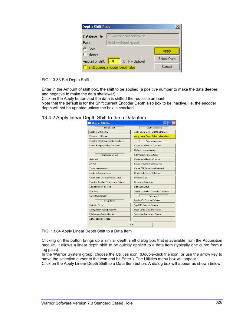
FIG: 13.83 Set Depth Shift
Enter in the Amount of shift box, the shift to be applied (a positive number to make the data deeper, and negative to make the data shallower). Click on the Apply button and the data is shifted the requisite amount.Note that the default is for the Shift current Encoder Depth also box to be inactive, i.e. the encoder depth will not be updated unless the box is checked.
13.4.2 Apply linear Depth Shift to the a Data item
FIG: 13.84 Apply Linear Depth Shift to a Data Item
Clicking on this button brings up a similar depth shift dialog box that is available from the Acquisition module. It allows a linear depth shift to be quickly applied to a data item (typically one curve from a log pass). In the Warrior System group, choose the Utilities icon. (Double-click the icon, or use the arrow key to move the selection cursor to the icon and hit Enter.). The Utilities menu box will appear. Click on the Apply Linear Depth Shift to a Data Item button. A dialog box will appear as shown below:
327 Warrior Software Version 7.0 Standard Cased Hole
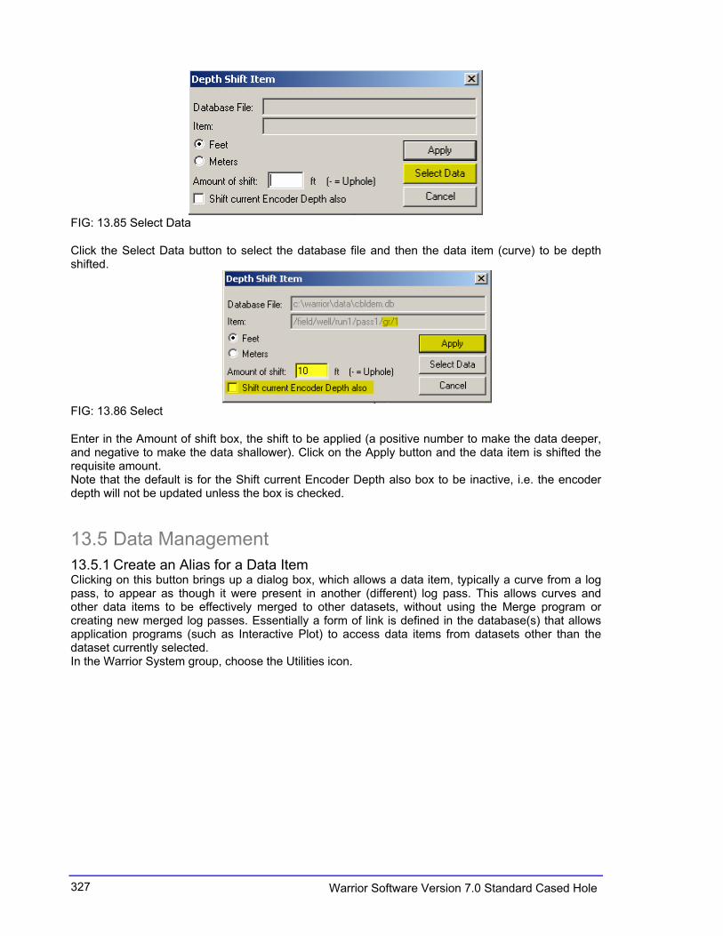
FIG: 13.85 Select Data
Click the Select Data button to select the database file and then the data item (curve) to be depth shifted.
FIG: 13.86 Select
Enter in the Amount of shift box, the shift to be applied (a positive number to make the data deeper, and negative to make the data shallower). Click on the Apply button and the data item is shifted the requisite amount. Note that the default is for the Shift current Encoder Depth also box to be inactive, i.e. the encoder depth will not be updated unless the box is checked.
13.5 Data Management
13.5.1 Create an Alias for a Data Item Clicking on this button brings up a dialog box, which allows a data item, typically a curve from a log pass, to appear as though it were present in another (different) log pass. This allows curves and other data items to be effectively merged to other datasets, without using the Merge program or creating new merged log passes. Essentially a form of link is defined in the database(s) that allows application programs (such as Interactive Plot) to access data items from datasets other than the dataset currently selected. In the Warrior System group, choose the Utilities icon.

328Warrior Software Version 7.0 Standard Cased Hole
FIG: 13.87 Select Create an Alias for a Data Item
Click on the Create an Alias for a Data Item button. A dialog box will appear as shown below:
FIG: 13.88 Browse DataBase
Click the Browse button and select the database file, then the dataset (log pass) and finally the data item to aliased. In the case shown below the curve GR has been selected from pass12 of the cbldemo.db database.

329 Warrior Software Version 7.0 Standard Cased Hole
FIG: 13.89 Create data Item Alias
This is the database item to be aliased to another pass. In the New Name for item field replace any or the entire data item path. For example if we want this GR curve to appear in pass1, we type over pass12 with pass1, as shown below:
FIG: 13.90 Create Pass1
The OK button is clicked and the GR curve from pass12 will now appear in pass1. If a curve with the same name already exists in pass1 then the program will give a message indicating that this is the case and the alias will not be performed. The easiest thing to do in this case is to rename the GR curve to something else (which does not already exist in that pass) e.g. GR2.
FIG: 13.91 Create GR2 Curve
Clicking the OK button will now alias the pass12 GR curve to pass1 as GR2. Note that if you now wish to plot this curve it will be necessary to include a curve called GR2 in the presentation file with which the pass will be plotted. Note that a linear depth offset may be applied to the data item as it aliased, so if the curve is not depth aligned with the other data in the destination path, it may be corrected at this point. Note also that no new log passes are created in this process and the size of the database(s) remains the same. This is very important when wishing to present waveform data from several passes simultaneously, as large amounts of data would otherwise be created.
330Warrior Software Version 7.0 Standard Cased Hole
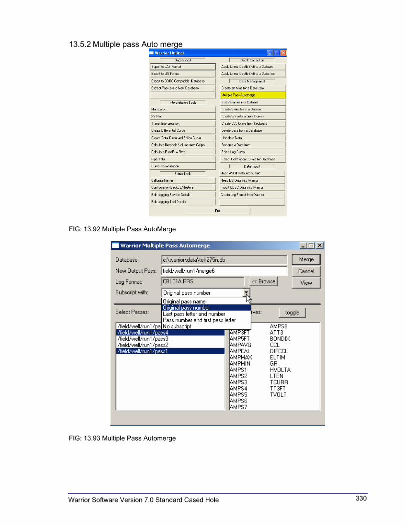
13.5.2 Multiple pass Auto merge
FIG: 13.92 Multiple Pass AutoMerge
FIG: 13.93 Multiple Pass Automerge

331 Warrior Software Version 7.0 Standard Cased Hole
FIG: 13.94 Set Passes and Curves
FIG: 13.95 Four new aliases curves
332Warrior Software Version 7.0 Standard Cased Hole
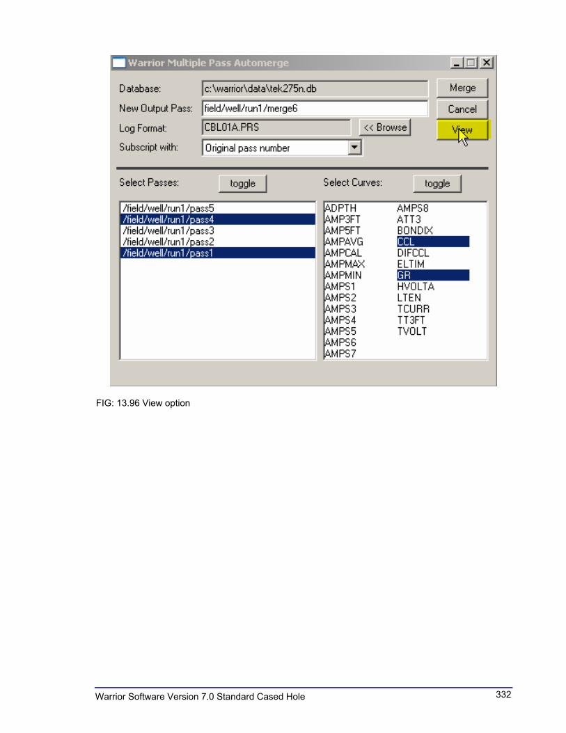
FIG: 13.96 View option
333 Warrior Software Version 7.0 Standard Cased Hole
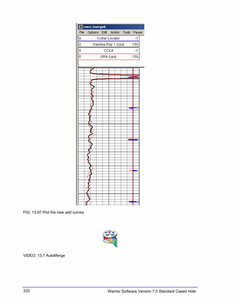
FIG: 13.97 Plot the new add curves
VIDEO: 13.7 AutoMerge
334Warrior Software Version 7.0 Standard Cased Hole
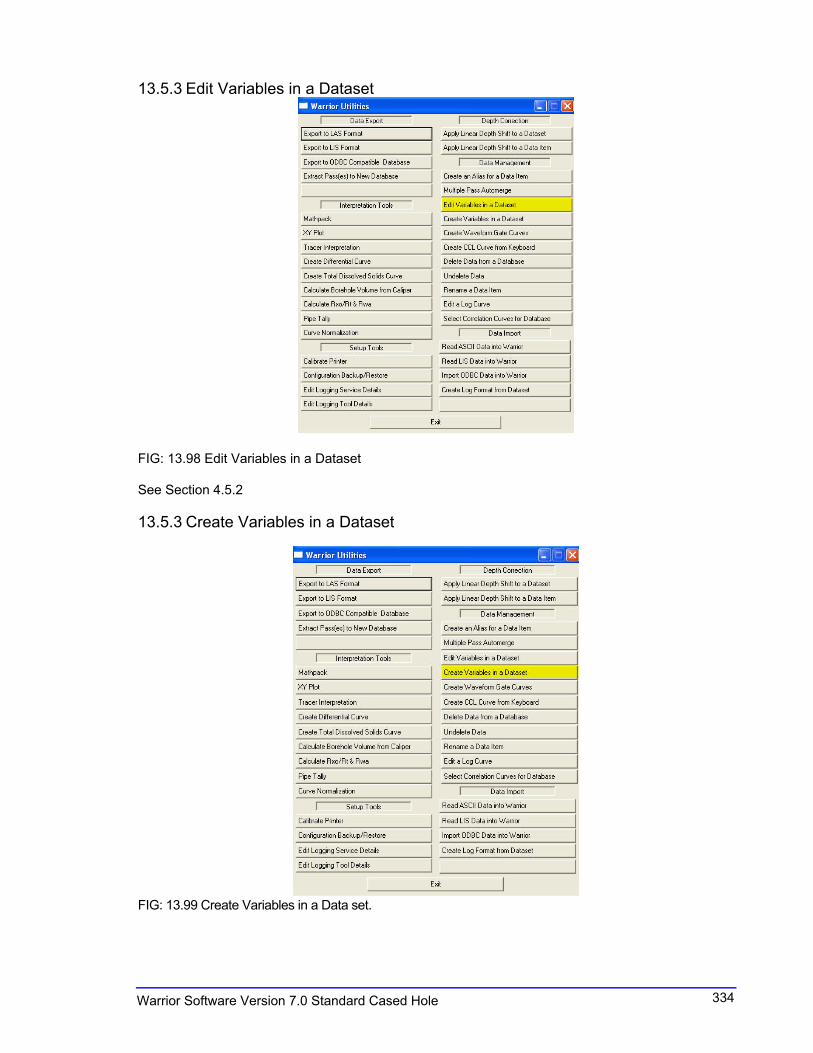
13.5.3 Edit Variables in a Dataset
FIG: 13.98 Edit Variables in a Dataset
See Section 4.5.2
13.5.3 Create Variables in a Dataset
FIG: 13.99 Create Variables in a Data set.

335 Warrior Software Version 7.0 Standard Cased Hole
13.5.6 Create Waveform Gate Curves
FIG: 13.100 Create Waveform Gate Curves
13.5.6 Create CCL Curve from Keyboard
FIG: 13.101 Create CCL Curve from Keyboard

336Warrior Software Version 7.0 Standard Cased Hole
13.5.7 Delete Data from a Database
FIG: 13.102 Select Delete data from a Database
FIG: 13.103 Delete Individual Item(s)
To delete a database item e.g. a curve, click on Delete Individual Item(s). The standard database file selection dialog appears.

337 Warrior Software Version 7.0 Standard Cased Hole
FIG: 13.104 Select Database
After selecting the database, the dialog for selection of the data item appears. Select the data item(s) to be deleted. All or no items may be selected by using the Toggle button.
FIG: 13.105 Select Items
A warning message appears informing that permanent data deletion is about to take place.

338Warrior Software Version 7.0 Standard Cased Hole
FIG: 13.106 Permanent Data Deletion
DATA DELETED WITH THIS UTILITY CANNOT BE RECOVERED
Clicking Yes in the above aborts the operation. Clicking No proceeds with the operation and allows the choice to repack the database file immediately or to defer the operation until later.
FIG: 13.107 Deletion
FIG: 13.108 Packing
Clicking Yes causes the data item to be removed and the database repacked immediately and clicking No marks the data item for deletion, buts defers the packing of the data base.
VIDEO: 13.8 Deleted data

339 Warrior Software Version 7.0 Standard Cased Hole
13.5.8 Undelete Data
FIG: 13.109 Undelete Data
13.5.9 Rename a Data Item
FIG: 13.110 Rename a Data Item

340Warrior Software Version 7.0 Standard Cased Hole
13.5.10 Edit a Log Curve
FIG: 13.111 Edit a Log Curve
FIG: 13.112 Select Pass for Curve to edit

341 Warrior Software Version 7.0 Standard Cased Hole
FIG: 13.113 Select Curve
FIG: 13.114 Plot Curve

342Warrior Software Version 7.0 Standard Cased Hole
FIG: 13.115 Zoom Curve
FIG: 13.116 Draw Curve
FIG: 13.117 Curve List
343 Warrior Software Version 7.0 Standard Cased Hole
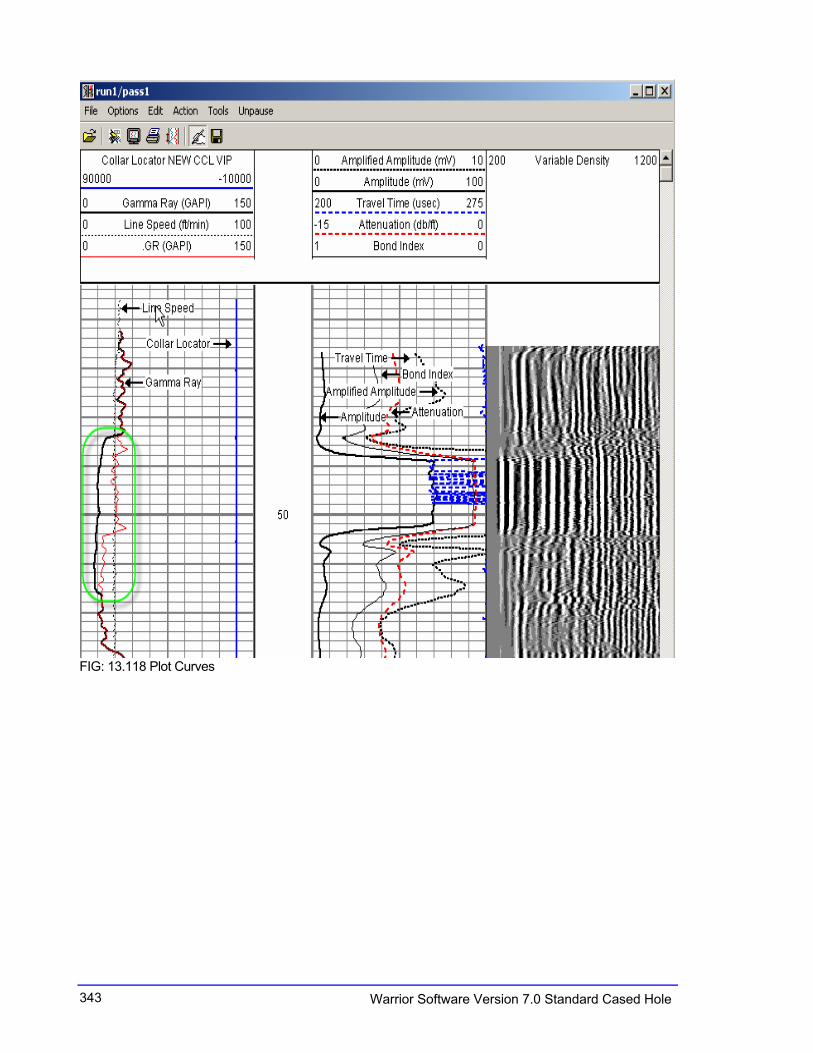
FIG: 13.118 Plot Curves
344Warrior Software Version 7.0 Standard Cased Hole
13.5.11 Select Correlations Curves from Data Base
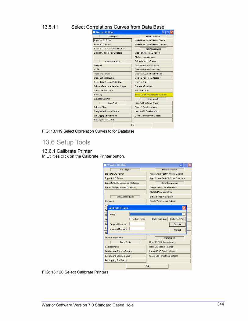
FIG: 13.119 Select Correlation Curves to for Database
13.6 Setup Tools
13.6.1 Calibrate Printer In Utilities click on the Calibrate Printer button.
FIG: 13.120 Select Calibrate Printers

345 Warrior Software Version 7.0 Standard Cased Hole
FIG: 13.121 Select from Hardcopy Calibrate
Select the printer to calibrate using the selection box. This printer may be made the Default Printer by checking the Default Printer box.
FIG: 13.122 Select Make Test Print
FIG: 13.123 Select Database to Plot
The calibration is based on two parameters entered by the user. Enter the required length of print output for any given log interval, e.g. 10 inches for 200 feet of log on a 5-inch scale (5 in = 100Ft). It means Scale 1: 240. Enter the actual length of plot currently output by the plotter for the same log interval. Press Calibrate.
346Warrior Software Version 7.0 Standard Cased Hole
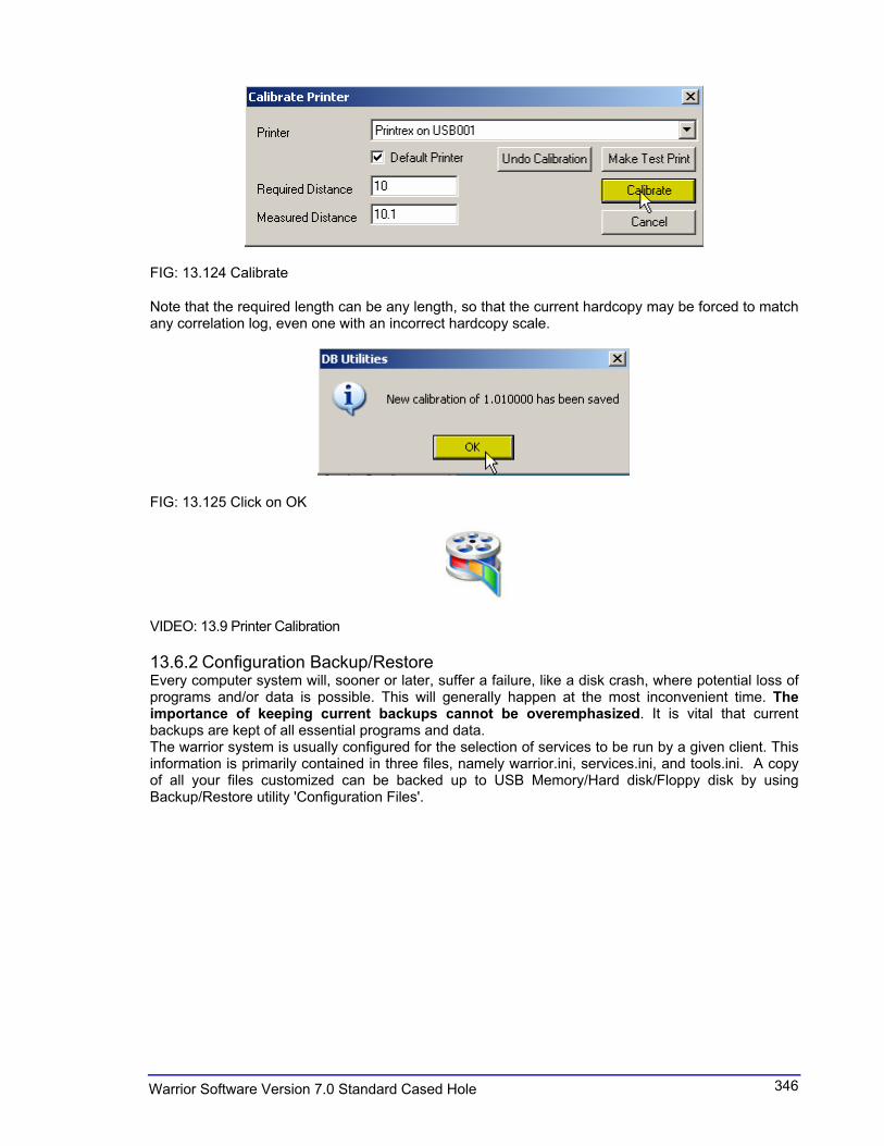
FIG: 13.124 Calibrate
Note that the required length can be any length, so that the current hardcopy may be forced to match any correlation log, even one with an incorrect hardcopy scale.
FIG: 13.125 Click on OK
VIDEO: 13.9 Printer Calibration
13.6.2 Configuration Backup/Restore Every computer system will, sooner or later, suffer a failure, like a disk crash, where potential loss of programs and/or data is possible. This will generally happen at the most inconvenient time. The importance of keeping current backups cannot be overemphasized. It is vital that current backups are kept of all essential programs and data. The warrior system is usually configured for the selection of services to be run by a given client. This information is primarily contained in three files, namely warrior.ini, services.ini, and tools.ini. A copy of all your files customized can be backed up to USB Memory/Hard disk/Floppy disk by using Backup/Restore utility 'Configuration Files'.
347 Warrior Software Version 7.0 Standard Cased Hole
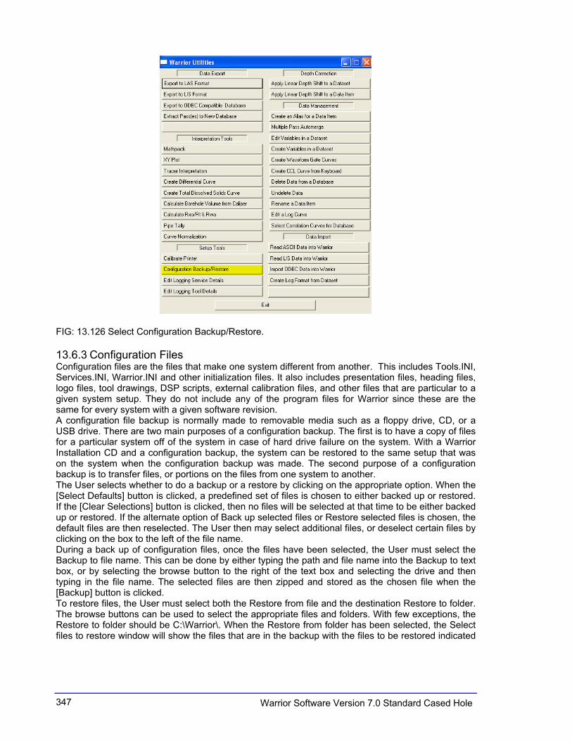
FIG: 13.126 Select Configuration Backup/Restore.
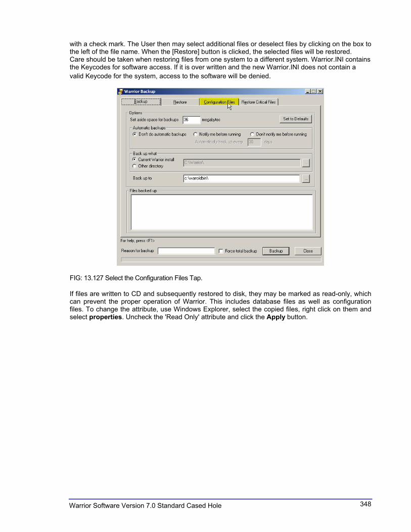
13.6.3 Configuration Files Configuration files are the files that make one system different from another. This includes Tools.INI, Services.INI, Warrior.INI and other initialization files. It also includes presentation files, heading files, logo files, tool drawings, DSP scripts, external calibration files, and other files that are particular to a given system setup. They do not include any of the program files for Warrior since these are the same for every system with a given software revision. A configuration file backup is normally made to removable media such as a floppy drive, CD, or a USB drive. There are two main purposes of a configuration backup. The first is to have a copy of files for a particular system off of the system in case of hard drive failure on the system. With a Warrior Installation CD and a configuration backup, the system can be restored to the same setup that was on the system when the configuration backup was made. The second purpose of a configuration backup is to transfer files, or portions on the files from one system to another. The User selects whether to do a backup or a restore by clicking on the appropriate option. When the [Select Defaults] button is clicked, a predefined set of files is chosen to either backed up or restored. If the [Clear Selections] button is clicked, then no files will be selected at that time to be either backed up or restored. If the alternate option of Back up selected files or Restore selected files is chosen, the default files are then reselected. The User then may select additional files, or deselect certain files by clicking on the box to the left of the file name. During a back up of configuration files, once the files have been selected, the User must select the Backup to file name. This can be done by either typing the path and file name into the Backup to text box, or by selecting the browse button to the right of the text box and selecting the drive and then typing in the file name. The selected files are then zipped and stored as the chosen file when the [Backup] button is clicked. To restore files, the User must select both the Restore from file and the destination Restore to folder. The browse buttons can be used to select the appropriate files and folders. With few exceptions, the Restore to folder should be C:\Warrior\. When the Restore from folder has been selected, the Select files to restore window will show the files that are in the backup with the files to be restored indicated
348Warrior Software Version 7.0 Standard Cased Hole
with a check mark. The User then may select additional files or deselect files by clicking on the box to the left of the file name. When the [Restore] button is clicked, the selected files will be restored. Care should be taken when restoring files from one system to a different system. Warrior.INI contains the Keycodes for software access. If it is over written and the new Warrior.INI does not contain a
valid Keycode for the system, access to the software will be denied.
FIG: 13.127 Select the Configuration Files Tap.
If files are written to CD and subsequently restored to disk, they may be marked as read-only, which can prevent the proper operation of Warrior. This includes database files as well as configuration files. To change the attribute, use Windows Explorer, select the copied files, right click on them and select properties. Uncheck the 'Read Only' attribute and click the Apply button.
349 Warrior Software Version 7.0 Standard Cased Hole
FIG: 13.128 Type Drive, File Name and Select Backup
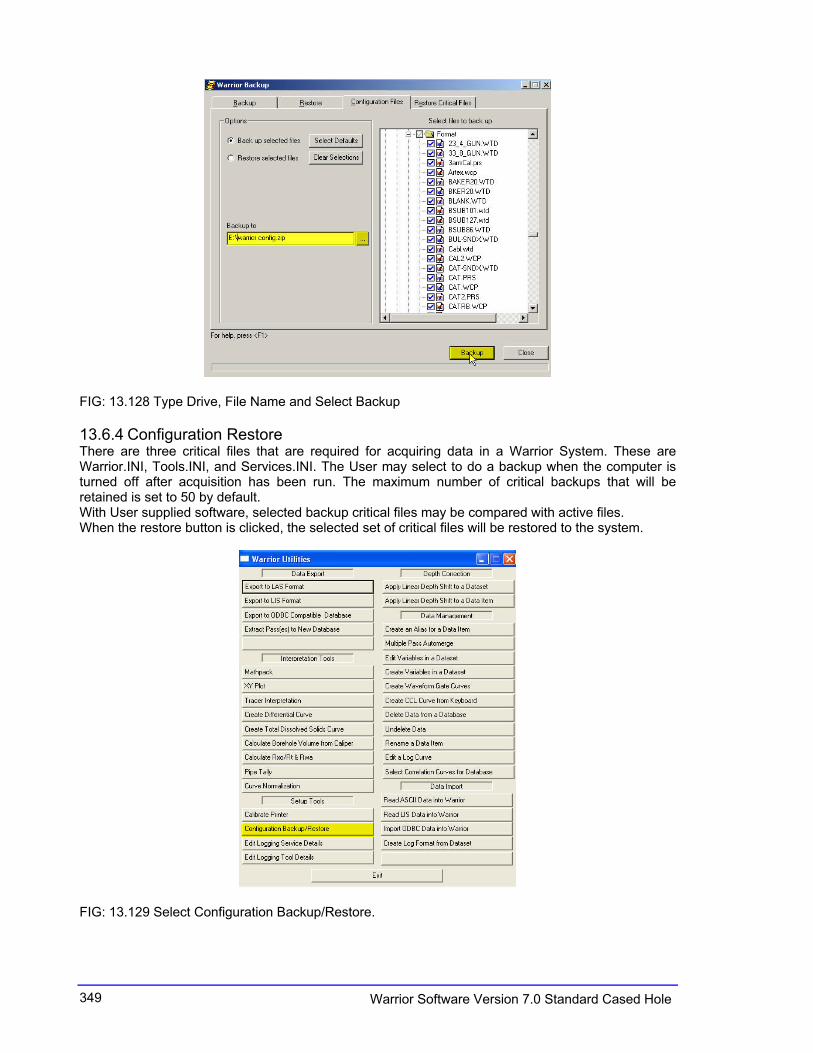
13.6.4 Configuration Restore There are three critical files that are required for acquiring data in a Warrior System. These are Warrior.INI, Tools.INI, and Services.INI. The User may select to do a backup when the computer is turned off after acquisition has been run. The maximum number of critical backups that will be retained is set to 50 by default. With User supplied software, selected backup critical files may be compared with active files. When the restore button is clicked, the selected set of critical files will be restored to the system.
FIG: 13.129 Select Configuration Backup/Restore.

350Warrior Software Version 7.0 Standard Cased Hole
FIG: 13.130 Restore Select files
FIG: 13.131 Restore All Files
Restore of all your files customized can be restore from a USB Memory/Hard disk/Floppy by using Restore utility 'Configuration Files'. It means you restore all your presentations, tools string, services, key codes, etc.

351 Warrior Software Version 7.0 Standard Cased Hole
13.6.5 Warrior Backup Warrior Backup is a utility used to backup and restore Warrior Software files. This can be a full backup of all files or a partial backup of only the files that have changed since the last backup. It can also be a backup of only the configurations files that distinguish the system from other warrior systems.
FIG: 13.132 Backup set to Defaults
There are two typical procedures to start Warrior Backup. The first method is to select Warrior Backup from the Warrior 7.0 program group that is normally placed on the Windows desktop or from the Windows program list. Warrior Utilities could also be selected in the same manner, and then click on the Configuration Backup/Restore selection under Setup Tools. There are four page selections at the top of the Warrior Backup window, Backup, Restore, Configuration Files, and Restore Critical Files. Backup performs a backup of Warrior files to a drive on the computer. Restore will restore Warrior files done in a Backup into the Warrior folder on the computer. Configuration files for the Warrior System can be backed up and restored from this page. The three critical files, Warrior.ini, Services.ini, and tools.ini can be automatically backed up every time the computer is rebooted and then later restored from any of the backups. A short help file for each page is available by pressing the F1 key on the Keyboard.
13.6.6 Backup Page The purpose of the Warrior Backup is to make a copy of the existing Warrior program, configuration, and auxiliary files. This is done so that if problems are found in files, either through the User making incorrect changes, a new bug in the software, or similar problems, then the User can restore the Warrior files to a know set of files that worked correctly for him. There are several options that can be set before a backup is performed. By clicking the [Set to Defaults] button in the upper right of the page, many of these will be performed automatically. Either incremental or full backups can be done. The default is to do an incremental backup of only the files that have changed since the last backup.

352Warrior Software Version 7.0 Standard Cased Hole
FIG: 13.133 Backup Browse
The maximum disk space that will be used for backup storage is initially set to 400 megabits. The default size will change depending upon the contents of the files in the Warrior Folder, but can be set by the User to any desired number of megabytes. If the maximum limit is exceeded, the User will be notified and asked if he wants to remove the oldest backup, this will be repeated until there is room for the backup to be completed or the User does not allow the oldest backup to be removed. The backup will then be performed, even if after the User has told it not to remove backups, it exceeds the maximum disk space set aside. Automatic backups can be performed by the Warrior system or can be turned off. It is recommended that automatic backups be done. The User can select whether he is notified that a backup is about to be done or not. If he is notified, he can elect to cancel the backup at that time. The default frequency for automatic backups is 30 days but can be set by the user. Normally the current Warrior installation directory is chosen for the files that are to be backed up, but the user can choose an alternate directory that contains Warrior files by clicking on the browse button. The backup location is initially set to the C:\warroldbin\ folder, but can be changed to a new or different folder by entering a new folder name in the text box, or by clicking on the browse button immediately to the right of the text box.

353 Warrior Software Version 7.0 Standard Cased Hole
FIG: 13.134 Other directory Backup
A text box is provided for the User to add additional information as to the reason the backup was done. This is to aid in selecting an appropriate backup set to restore. If a full backup of Warrior files is desired, then checking the Force total backup check box will do a backup of all files, otherwise an incremental backup of only the files that have changed since the last backup will be done.
13.6.7 Restore page The restore page is used to restore the files made from previous Warrior backups that have been done on that particular system. Once the files have been restored, the system will be set up with the same files that it had when the restore was done. The Restore from default directory is C:\warroldbin\ and the Restore to default directory is C:\Warrior\. Each of these directories can be changed by clicking on the browse button to the right of the text boxes. Once a directory to restore from has been chosen, a list of Backup dates in that directory will be shown. Dates of full backups will be marked with an asterisk (*). When a date has been selected, a complete list of the files backed up on that date and a list of files that are different than the current files in the Restore to directory will be shown. Initially all files will be selected to restore. The User may wish to only restore certain files. He can do this by clicking on the [Clear Selected] button, then

354Warrior Software Version 7.0 Standard Cased Hole
clicking on the changed file that he wishes to restore. The User may restore multiple selections by holding down on the control key {ctrl} and then clicking on each file that he wishes to have restored.
FIG: 13.135 Restore Browse
When the [Restore] button is clicked, the selected files will be restored to the Restore to directory.
VIDEO: 13.10 Backup/Restore
13.7 Edit Logging service Details See Section 5
13.8 Edit Logging Tools Details. See Section 6