warrell creek to urunga pacific highway … · warrell creek to urunga pacific highway upgrade...
TRANSCRIPT

Coffey Geotechnics Pty Ltd ABN 93 056 929 483 8/12 Mars Road Lane Cove West NSW 2066 Australia
WARRELL CREEK TO URUNGA PACIFIC HIGHWAY UPGRADE ALTERNATIVE ALIGNMENT REVIEW
Roads and Maritime Services GEOTLCOV24043AF-AC Rev 2 22 December 2011

Coffey Geotechnics Pty Ltd ABN 93 056 929 483 GEOTLCOV24043AF-AC Rev 2 8/12 Mars Road Lane Cove West NSW 2066 Australia PO Box 125 North Ryde NSW 1670 Australia T (+61) (2) 9911 1000 F (+61) (2) 9911 1001 coffey.com
22 December 2011
Roads and Maritime Services 76 Victoria Ave GRAFTON NSW
Attention: Shane Green
Dear Sir
RE: Warrell Creek to Urunga
Alternative Alignment Review
This report provides the findings of a geotechnical assessment of the alternative alignment for the Pacific Highway upgrade section from Warrelll Creek to Urunga. Coffey Geotechnics Pty Ltd (Coffey) has prepared this report for the technical review of the alternative alignment. The contents of this report are based on a desktop study of existing surface and subsurface conditions obtained from studies and investigations for the approved alignment.
Should you have any queries or comments regarding this report, please contact the undersigned.
For and on behalf of Coffey Geotechnics Pty Ltd
Paran Moyes
Associate Geotechnical Engineer
cc Shane Higgins SMEC
Distribution: Original held by Coffey Geotechnics Pty Ltd
1 copy held by Coffey Geotechnics Pty Ltd
1 electronic copy to RMS
1 electronic copy to SMEC
CONTENTS
Coffey Geotechnics GEOTLCOV24043AF-AC Rev 2 22 December 2011
i
1 INTRODUCTION 1
2 PROPOSED ROUTE 1
2.1 Approved alignment 1
2.2 Alternative Alignment 1
3 SITE DESCRIPTION 2
3.1 Regional Topography and Terrain 2
3.2 Regional Geological Setting 2
3.2.1 Holocene Sediments 2
3.2.2 Pleistocene Sediments 2
3.2.3 Gully Alluvium 3
3.2.4 Phyllite 3
3.3 Geotechnical Information Available 4
3.4 Alternative Alignment Topography and Assessed Subsurface Conditions 5
3.5 Land Use 10
4 GEOTECHNICAL UNITS 12
5 ACID SULPHATE SOIL AND CONTAMINATION 14
6 ENGINEERING ASSESSMENT 14
6.1 Cuttings 14
6.1.1 Excavation of Cuttings 14
6.1.2 Cut Batter Design 14
6.1.3 Material from Cuttings and Reuse Potential 15
6.1.4 Unsuitable Materials 17
6.1.5 Cut Foundation Treatments 17
6.1.6 Transition Zones at Cut/Fill Interface 18
6.2 Embankments 19
6.2.1 General Embankment Design Criteria 19
6.2.2 Embankment Foundation Preparation and Treatments 20
6.2.3 Embankment Settlement 21
6.3 Soft Ground Engineering 23
6.3.1 Introduction 23
6.3.2 Locations of soft ground 23
6.3.3 Settlement design criteria 24
6.3.4 Surcharge and settlement estimates 25
6.3.5 Ground improvement 26
6.4 Bridge Foundations and Construction Issues 33
CONTENTS
Coffey Geotechnics GEOTLCOV24043AF-AC Rev 2 22 December 2011
ii
6.5 Culverts 33
7 GEOTECHNICAL ISSUES - APPROVED ALIGNMENT AND ALTERNATIVE ALIGNMENT 37
8 CONDITIONS OF THIS REPORT 38
Important Information About Your Coffey Report
Tables
Table 3.1 Review of Historical Aerial Photographs for Former Quarry
Table 4.1 Alternative Alignment Geotechnical Units
Table 6.1 Summary of Weathered Rock CBR Testing
Table 6.2 Summary of Cuttings
Table 6.3 Summary of Embankments
Table 6.4 Summary of Soft Ground Locations
Table 6.5 Summary of Proposed Post Construction Settlement Criteria for Preliminary Design
Table 6.6 Estimated Surcharge Requirements and Associated Settlements
Table 6.7 Potential Ground Treatment Methods
Table 6.8 Design Concepts for CIC Supported Embankments
Table 6.9 Suitability of Ground Improvement Methods
Table 6.10 Summary of Culverts
Table 7.1 Geotechnical Issues – Approved and Alternative Alignment
Figures
Figure 3.1 Weathering Profile Developed on Schistose Rock
Photos
Photo 3.1 Nambucca River Floodplain (southern side of river)
Photo 3.2 End of Ridgeline near Ch 12 150m
Photo 3.3 Nambucca River Floodplain looking North
Photo 3.4 Surface water on Floodplain Looking Southeast form Mattick Lane

CONTENTS
Coffey Geotechnics GEOTLCOV24043AF-AC Rev 2 22 December 2011
iii
Photo 3.5 Weathered Phyllite Exposure in Cutting on Old Coast Road
Photo 3.6 Weathered Phyllite Overlain by Soil in Old Coast Road Cutting
Appendices
Appendix A: Site Plans
Appendix B: Geotechnical Long Sections
Alternative Alignment Review
Coffey Geotechnics GEOTLCOV24043AF-AC Rev 2 22 December 2011
1
1 INTRODUCTION
This report provides Coffey Geotechnics’ Pty Ltd (Coffey’s) geotechnical assessment for the technical review of the alternative alignment for the Warrell Creek to Urunga Pacific Highway Upgrade. Following community requests, Roads and Maritime Services (RMS) is undertaking a technical review of the alternative alignment to evaluate the constraints associated with the alternative alignment and compares it with the approved route. RMS engaged Coffey on 31 October 2011 to undertake a geotechnical assessment comprising a desktop assessment for input into the technical review. This work was carried out in general accordance with our proposal ref GEOTLCOV24043AF-AA dated 21 October 2011.
2 PROPOSED ROUTE
2.1 Approved alignment
The approved alignment extends north of the Bald Hill Road interchange traversing the Gumma Swamp floodplain to the east of Macksville, before crossing the Nambucca River just to the west of the Macksville Sewage Treatment Plant (STP). A new bridge, approximately 830m long, would be constructed across the Nambucca River.
North of the Nambucca River, the approved alignment crosses the existing Pacific Highway approximately 150 metres to the west of Old Coast Road. The approved alignment then generally follows the ridgeline in the vicinity of Old Coast Road, initially to the east of the ridgeline then crossing to the west before then passing through the Nambucca State Forest.
2.2 Alternative Alignment
The alternative alignment deviates east from the approved alignment north of the Bald Hill Road interchange at approximate chainage 8700, to the south of the Nambucca Council Depot and Sewage Treatment Plant. The alternative alignment then proceeds in a north-easterly direction traversing the Gumma Swamp floodplain and a section of SEPP 14 wetland (No. 388) to the east of Macksville, before crossing the Nambucca River just to the east of Goat Island.
A new bridge approximately 1 400 metres long would be constructed across the Nambucca River crossing Gumma Road on the southern side and the existing Pacific Highway on the northern side of the river. Presently oyster leases and SEPP 14 wetland are impacted by the alternative alignment.
North of the Nambucca River, the alternative alignment heads north through agricultural lands to the east of the approved alignment running parallel to the west of Watt Creek before crossing Mattick Road. From here the alternative alignment continues north, running on the eastern side of a ridge line and Old Coast Road. At this point the alternative alignment passes to the west of Kingsworth Estate before connecting back to the approved alignment at approximate chainage Ch 16500m, south west of Nambucca Heads through the Nambucca State Forest.

Alternative Alignment Review
Coffey Geotechnics GEOTLCOV24043AF-AC Rev 2 22 December 2011
2
3 SITE DESCRIPTION
3.1 Regional Topography and Terrain
The topographic setting for the alternative alignment of the Warrell Creek to Nambucca Heads highway upgrade is dominated by low, east-west trending, rounded ridgelines, relatively narrow valleys between the ridgelines and a broad alluvial floodplain associated with the Nambucca River. Along the upgrade alignment, the gently undulating foothills are elevated to about RL45m north of the Nambucca River. Ground slopes flanking the low ridgelines are typically less than 10°.
Between the low ridgelines are small meandering watercourses typically about 5m wide within valleys of about 100m to 250m width. The wider valley floors can be associated with localised areas of “boggy ground” following prolonged rainfall.
The Nambucca River crossing, located 2.8km east of Macksville, is about 400mm wide, with the river located in the northern portion of a 3.5km wide floodplain. The floodplain is at a surface elevation ranging from RL0.9m to RL3m.
Land use along the upgrade alignment is predominantly farming in the form of cattle grazing or smaller hobby farms. The Nambucca State Forest occupies the northern portion of the study area. An area of privately owned forest is located between chainages Ch 13 700m and Ch 14 600m.
3.2 Regional Geological Setting
The following section describes the regional geological units that have been identified in this portion of the Warrell Creek to Urunga study. This information is based on the geology encountered in the studies of the approved alignment. The geology is dominated by Holocene and Pleistocene age alluvial deposits in the Nambucca River Floodplain. In the vicinity of Old Coast Road the geology is dominated by deeply weathered Phyllite bedrock.
3.2.1 Holocene Sediments
Holocene sediments are present within the floodplain of the Nambucca River. The Holocene sediments form the uppermost Quaternary sediment sequence in these areas, and overlie the older Pleistocene deposits of the Nambucca River floodplain. Approximately 950m of the alternative alignment is underlain by Holocene soils 5m to 15m thick, and approximately 2,000m of alternative alignment is underlain by Holocene soils 15m to 18m thick.
The Holocene sediments at the Nambucca River are typically characterised by grey and dark grey soft to firm estuarine clays, silts and sands, often with shells and shell fragments. Analytical tests performed on the Holocene deposits suggest that these sediments originate from the weathering and erosion of the neighbouring low grade metamorphic terrain giving rise to non-reactive clay species (predominantly illites).
3.2.2 Pleistocene Sediments
Inferred Pleistocene sediments are present along the alternative alignment associated with the very broad floodplain of the Nambucca River. The Pleistocene deposits form the basal Quaternary sediment sequence in this area and are overlain by younger Holocene sediments.

Alternative Alignment Review
Coffey Geotechnics GEOTLCOV24043AF-AC Rev 2 22 December 2011
3
The Pleistocene sediments at the Nambucca River consist of basal sands and gravels at depth (up to depths of 25m to 30m within gently incised palaeochannels) which are in turn overlain by a clay dominated sediment sequence. The Pleistocene clays are characterised by mottled red, orange and grey fissured stiff to very stiff clays. The Pleistocene deposits are complex and vary considerably laterally, as is characteristic of fluvial sediments.
Within the vicinity of the existing Nambucca River, the upper Pleistocene clay sequence has been incised through and eroded away so that the lower Pleistocene sequence is seen to be directly overlain by Holocene age sediments. Only at the northern and southern extents of the Nambucca River floodplain is the upper Pleistocene clay sequence at least in part preserved.
3.2.3 Gully Alluvium
More localised alluvial deposits (which may also have a significant colluvial component) occur within a number of locations along the alternative alignment within creeks and in the base of large gullies. These materials are generally limited to firm to very stiff clays with some interbedded sands and gravels and often form localised river terraces and former levees. These deposits are like to be complex and vary considerably laterally, as is characteristic of fluvial sediments.
3.2.4 Phyllite
Phyllite bedrock underlays the floodplain deposits and is exposed at the surface north from approximately Chainage Ch 13 700m onwards.
The Phyllite bedrock is characterised by a foliated, fine grained rock similar to sedimentary mudstone or shale but differentiated (where fresh) by a lustrous micaceous sheen characteristic of Phyllite rocks. Quartz veins are sparsely distributed throughout the unit, ranging from 5mm to 200mm in thickness. The Phyllite often exhibits a very deep weathering profile, with soil properties (typically very stiff to hard clayey silt with relict foliation) to depths of up to 40m, although more typically in the order of 5m to 20m.
The depth of weathering may vary considerably over short distances with some beds weathered to great depths and adjacent beds far less weathered (Figure 3.1). Beneath the floodplain deposits the weathered layers is relatively thin indicating erosion of the weathered Phyllite prior to the alluvial deposition.
Petrographically, the Phyllite is typically a tuffaceous low-grade metasedimentary rock consisting of extremely fine-grained, ash-derived quartz and feldspar. Some higher grade metamorphic examples tending towards low grade schist have also been recognised. Deformation has often resulted in a micaceous foliation and subtle crenuation. Coarser grained examples assessed as meta-greywacke likely represent clayey sand beds within the original sediment sequence. All samples contain a significant proportion of volcanic ash and detritus, a feature that is consistent with the regional geology which indicates these strata formed from the accumulation of volcanic detritus within a deep marine basin.
Structurally, the Phyllite is typically foliated at low- to high-angles where encountered in boreholes and it is likely that these low to high angles represent a series of fold limbs and hinges. Where the attitude of the foliation within the Phyllite could be observed along the Warrell Creek to Nambucca Heads alignment (for example within test pits), it was generally seen to be dipping either broadly north or broadly south at various angles. Observations made in cuttings along Old Coast Road in vicinity of the alternative alignment identified bedding dipping to the south at an angle of 10° to 15°. This is consistent with the literature for the area which suggests a broadly east-west striking structural trend

Alternative Alignment Review
Coffey Geotechnics GEOTLCOV24043AF-AC Rev 2 22 December 2011
4
(i.e. fold axes within the Nambucca Beds strata are likely to be oriented east-west with northerly and southerly dipping fold limbs).
Jointing within the Phyllite is generally at mid- to high-angles although no distinct and consistent joint sets have been identified. This is in accordance with the prolonged deformation history and multiple deformation episodes associated with these strata which would likely have resulted in a number of joint sets at various angles.
Although no distinct joint sets have been clearly defined, it is anticipated that a prominent north-south trending joint set associated with north-south compression of the Nambucca Block is likely to be present (and may be the reason many of the intrusive dykes in the area exhibit a northerly trend). If a prominent north-south trending joint set is present within these strata, this would strike sub-parallel to much of the proposed alignment and hence may have implications if steeper batter designs are to be considered within some cuts.
3.3 Geotechnical Information Available
Coffey has undertaken a significant number of investigations along the approved alignment as part of the geotechnical investigations for the Warrell Creek to Urunga project. This has included in the floodplain south of Gumma Road, along the approved bridge alignment in the Nambucca River, the floodplain north ofthe Nambucca River and along the Old Coast Road ridgeline. In all, Coffey has undertaken in excess of 30 testpits, 23 boreholes and 12 Cone Penetration Tests (CPTs) along the length of the approved alignment. In addition to the Coffey investigations, reference has been made to previous investigations undertaken for route selection studies.
In order to undertake the geotechnical assessment of the alternative alignment, reference was made to nearby available subsurface information. Site observations and geotechnical information available in similar topography and geomorphological environments to those observed along the alternative alignment were used in formulate the geotechnical model for the alternative alignment.
Figure 3.1 – Weathering profile developed on schistose rock with steeply dipping foliation (from Stapledon in Fell et al., 2006);
Alternative Alignment Review
Coffey Geotechnics GEOTLCOV24043AF-AC Rev 2 22 December 2011
5
3.4 Alternative Alignment Topography and Assessed Subsurface Conditions
An Associate Geotechnical Engineer from Coffey’s Sydney office made a visit to the alternative alignment on 8 November 2011. The purpose of the visit was to observe the site conditions and make an assessment of the subsurface conditions along the alternative alignment. No targeted subsurface investigations were carried out along the alternative alignment and reference was made to previous subsurface data in the general area. The site observations are provided in the sections below along with an assessment of the geological conditions. Site observations have also been presented on the Figures provided in Appendix A.
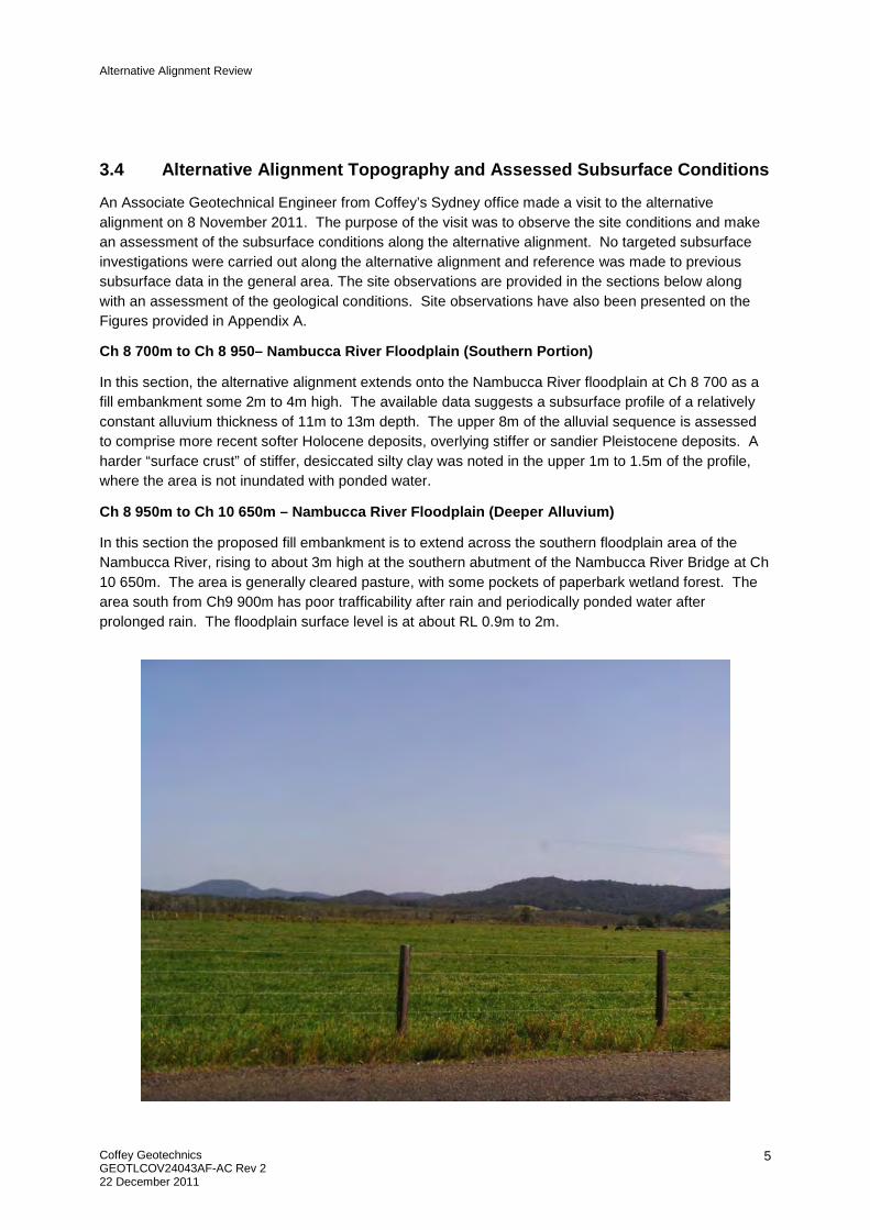
Ch 8 700m to Ch 8 950– Nambucca River Floodplain (Southern Portion)
In this section, the alternative alignment extends onto the Nambucca River floodplain at Ch 8 700 as a fill embankment some 2m to 4m high. The available data suggests a subsurface profile of a relatively constant alluvium thickness of 11m to 13m depth. The upper 8m of the alluvial sequence is assessed to comprise more recent softer Holocene deposits, overlying stiffer or sandier Pleistocene deposits. A harder “surface crust” of stiffer, desiccated silty clay was noted in the upper 1m to 1.5m of the profile, where the area is not inundated with ponded water.
Ch 8 950m to Ch 10 650m – Nambucca River Floodplain (Deeper Alluvium)
In this section the proposed fill embankment is to extend across the southern floodplain area of the Nambucca River, rising to about 3m high at the southern abutment of the Nambucca River Bridge at Ch 10 650m. The area is generally cleared pasture, with some pockets of paperbark wetland forest. The area south from Ch9 900m has poor trafficability after rain and periodically ponded water after prolonged rain. The floodplain surface level is at about RL 0.9m to 2m.
Alternative Alignment Review
Coffey Geotechnics GEOTLCOV24043AF-AC Rev 2 22 December 2011
6
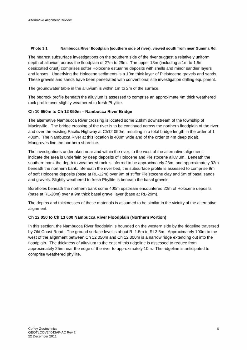
Photo 3.1 Nambucca River floodplain (southern side of river), viewed south from near Gumma Rd.
The nearest subsurface investigations on the southern side of the river suggest a relatively uniform depth of alluvium across the floodplain of 27m to 29m. The upper 18m (including a 1m to 1.5m desiccated crust) comprises softer Holocene estuarine deposits with shells and minor sandier layers and lenses. Underlying the Holocene sediments is a 10m thick layer of Pleistocene gravels and sands. These gravels and sands have been penetrated with conventional site investigation drilling equipment.
The groundwater table in the alluvium is within 1m to 2m of the surface.
The bedrock profile beneath the alluvium is assessed to comprise an approximate 4m thick weathered rock profile over slightly weathered to fresh Phyllite.
Ch 10 650m to Ch 12 050m – Nambucca River Bridge
The alternative Nambucca River crossing is located some 2.8km downstream of the township of Macksville. The bridge crossing of the river is to be continued across the northern floodplain of the river and over the existing Pacific Highway at Ch12 050m, resulting in a total bridge length in the order of 1 400m. The Nambucca River at this location is 400m wide and of the order of 4m deep (tidal). Mangroves line the northern shoreline.
The investigations undertaken near and within the river, to the west of the alternative alignment, indicate the area is underlain by deep deposits of Holocene and Pleistocene alluvium. Beneath the southern bank the depth to weathered rock is inferred to be approximately 28m, and approximately 32m beneath the northern bank. Beneath the river bed, the subsurface profile is assessed to comprise 9m of soft Holocene deposits (base at RL-12m) over 9m of stiffer Pleistocene clay and 5m of basal sands and gravels. Slightly weathered to fresh Phyllite is beneath the basal gravels.
Boreholes beneath the northern bank some 400m upstream encountered 22m of Holocene deposits (base at RL-20m) over a 9m thick basal gravel layer (base at RL-29m).
The depths and thicknesses of these materials is assumed to be similar in the vicinity of the alternative alignment.
Ch 12 050 to Ch 13 600 Nambucca River Floodplain (Northern Portion)
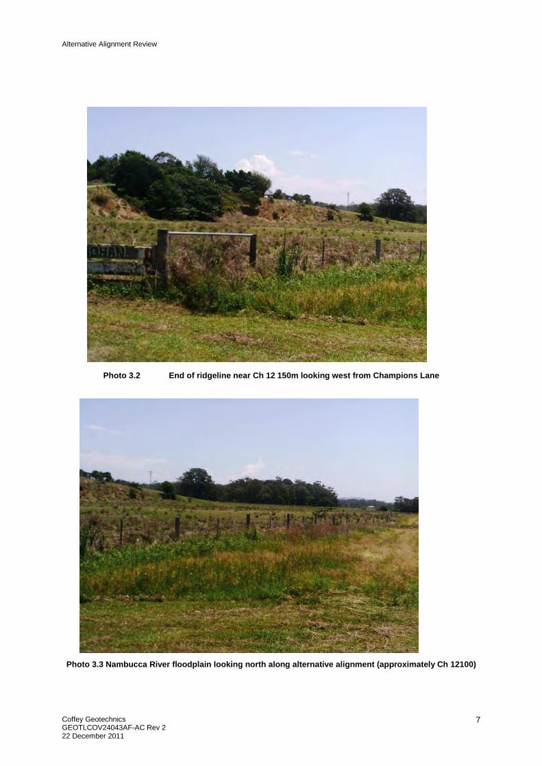
In this section, the Nambucca River floodplain is bounded on the western side by the ridgeline traversed by Old Coast Road. The ground surface level is about RL1.5m to RL3.5m. Approximately 100m to the west of the alignment between Ch 12 050m and Ch 12 300m is a narrow ridge extending out into the floodplain. The thickness of alluvium to the east of this ridgeline is assessed to reduce from approximately 25m near the edge of the river to approximately 10m. The ridgeline is anticipated to comprise weathered phyllite.
Alternative Alignment Review
Coffey Geotechnics GEOTLCOV24043AF-AC Rev 2 22 December 2011
7
Photo 3.2 End of ridgeline near Ch 12 150m looking west from Champions Lane
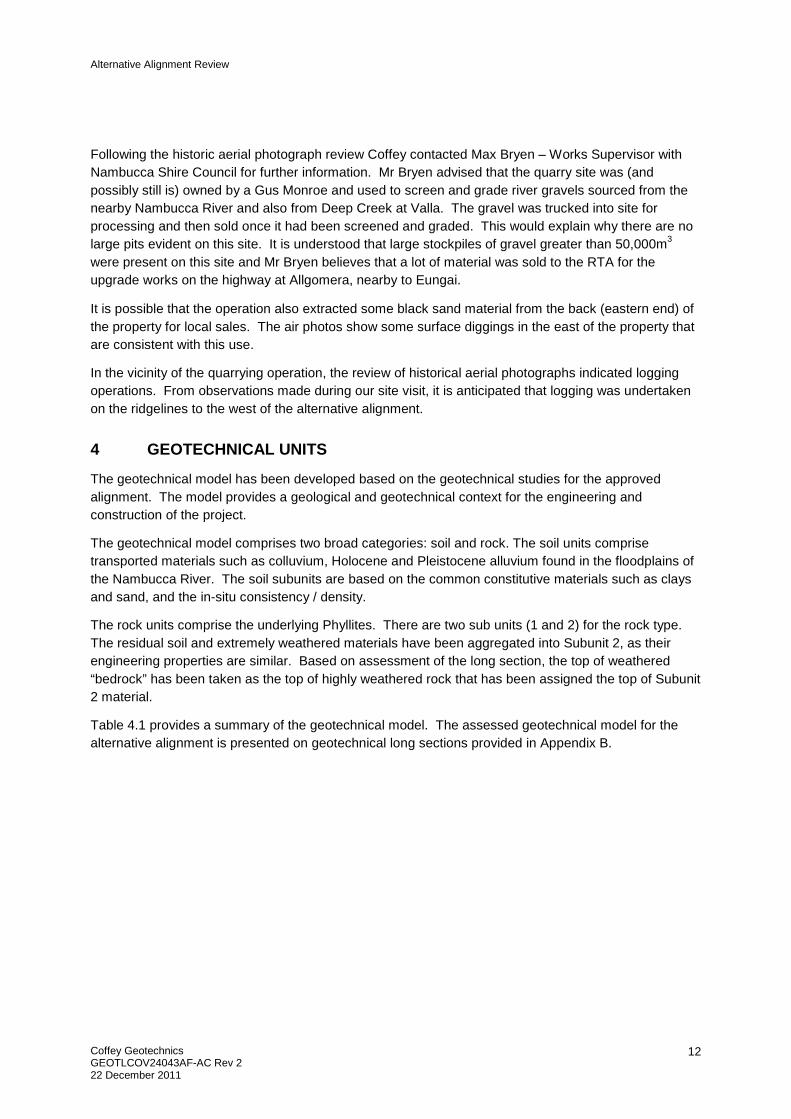
Photo 3.3 Nambucca River floodplain looking north along alternative alignment (approximately Ch 12100)

Alternative Alignment Review
Coffey Geotechnics GEOTLCOV24043AF-AC Rev 2 22 December 2011
8
The floodplain area is predominantly cleared farmland pasture with some stands of paperbark trees. A number of creeks and drainage channels cross the floodplain. At the time of the site visit significant amounts of surface water were observed in the numerous channels and depressions that are on the floodplain. Significant surface water was observed in the area south of Mattick Lane.
Photo 3.4 Surface water on floodplain looking southeast from Mattick Lane
It is anticipated that the thickness of Holocene alluvium in the area would be of the order of 12m to 15m with a surface crust of 1.5m to 2.5m. Where the alignment is closer to the ridgelines it is anticipated that the thickness of alluvium decreases to between 3m and 10m (approximately Ch 13150m to Ch 13600m)
Ch 13 600 to Ch 16 900– Undulating Farmland Slopes and Old Coast Road
In this section, an area of undulating slopes is located immediately to the west of the Nambucca River floodplain paralleling and crossing the alternative alignment. The alternative alignment cuts through relatively narrow ridgelines (with cut elevations of between RL 8m AHD and RL 32m AHD) and crosses east trending gullies and valleys (up to 500m wide), with a 10m to 20m difference in elevation. The Nambucca River has a northern trend some 2km to the east of the alignment. The floodplain extends to the foot slopes of the ridgelines containing the alternative alignment.

Alternative Alignment Review
Coffey Geotechnics GEOTLCOV24043AF-AC Rev 2 22 December 2011
9
The alternative alignment extends through cleared pasture farmland, smaller hobby farm allotments and forestry areas on private properties or in the Nambucca State Forest. Forested areas border Old Coast Road within the road reserve.
The valley and gully floor areas contain small incised gullies some 1m to 2m deep. As with areas investigated elsewhere on the alignment it is anticipated that these gully floors are underlain by very stiff colluvial (slopewash) clays 2m to 4m deep over highly to moderately weathered Phyllite.
The investigations undertaken for the approved alignment and observations made during the site indicate that the ridgelines are underlain by deeply weathered Phyllite with the following typical weathering profile beneath the ridgeline (cutting locations):
• 0m to 2m – Residual soil/extremely weathered Phyllite over, • 2m to about 25m – extremely weathered to moderately weathered Phyllite over, • >25m depth – slightly weathered Phyllite.
Photo 3.5 Weathered Phyllite exposure in Cutting on Old Coast Road (Approximate Ch 15150m)

Alternative Alignment Review
Coffey Geotechnics GEOTLCOV24043AF-AC Rev 2 22 December 2011
10
Photo 3.6 Weathered Phyllite overlain by Soil in Old Coast Road Cutting (Approximate Ch 15 400m)
3.5 Land Use
Based on previous Coffey studies, the cleared areas of the alternative alignment are understood to have been used primarily for cattle grazing. It is anticipated that some small cropping activities such as tomato growing may have also occurred.
In our aerial photograph assessment a potential former quarry was identified in the vicinity of Ch 14000m to 14 300m. Further investigation comprising a review of historic aerial photograph assessment was undertaken. The results are provided in Table 3.1 below.
.

Alternative Alignment Review
Coffey Geotechnics GEOTLCOV24043AF-AC Rev 2 22 December 2011
11
Table 3.1. Review of historical aerial photographs for the former Quarry / Gravel Pit Site on the Alternative Alignment – Nambucca River Crossing, Warrell Creek to Urunga Upgrade
Date Chainages Aerial Photograph Description Surrounding Landuses
1956 Ch 13500
to
Ch 14500
• Image is in black and white. • The alternative alignment passes over an area of native
bushland with adjacent low lying wetland areas. The wetland areas are generally orientated in a northwest to southeast direction.
• Two distinct cleared areas are present within bushland at approximately Ch14100.
• No quarrying activities are present.
• Surrounding areas are bushland and low lying wetlands. To the north of Ch14500 appears to be cleared grazing land.
• Some smaller paddocks located to the south and north of this area appear to be under cultivation, possibly for small crop horticulture.
1967 Ch13500 to Ch14500
• Image is in black and white. • Three distinct cleared areas are now present within bushland
at approximately Ch14100. • Cleared areas may now be used as a quarry/gravel pit
although no structures or plant can be identified on image.
• No significant change from 1956 photograph.
1980 Ch13500 to Ch14500
• Image is in black and white. • A larger area of clearing is now present to south west and the
development of small roads, possibly logging tracks and log dumps in the bushland areas.
• The previously three distinct cleared areas have now been consolidated into a single large area within bushland at approximately Ch14100.
• Cleared area appears to be used as a quarry/gravel pit. Dirt haul roads are in use leading to this site from Old Coast Road.
• Increase in development of logging roads in bushland areas to south and north of the quarry area.
• Clearing of bushland has occurred to the southwest and southeast for use as grazing land since 1967 photograph.
Alternative Alignment Review
Coffey Geotechnics GEOTLCOV24043AF-AC Rev 2 22 December 2011
12
Following the historic aerial photograph review Coffey contacted Max Bryen – Works Supervisor with Nambucca Shire Council for further information. Mr Bryen advised that the quarry site was (and possibly still is) owned by a Gus Monroe and used to screen and grade river gravels sourced from the nearby Nambucca River and also from Deep Creek at Valla. The gravel was trucked into site for processing and then sold once it had been screened and graded. This would explain why there are no large pits evident on this site. It is understood that large stockpiles of gravel greater than 50,000m3 were present on this site and Mr Bryen believes that a lot of material was sold to the RTA for the upgrade works on the highway at Allgomera, nearby to Eungai.
It is possible that the operation also extracted some black sand material from the back (eastern end) of the property for local sales. The air photos show some surface diggings in the east of the property that are consistent with this use.
In the vicinity of the quarrying operation, the review of historical aerial photographs indicated logging operations. From observations made during our site visit, it is anticipated that logging was undertaken on the ridgelines to the west of the alternative alignment.
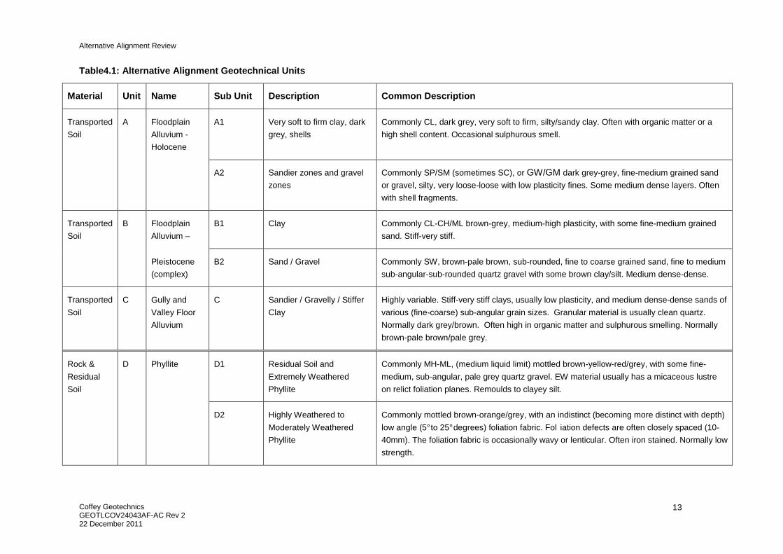
4 GEOTECHNICAL UNITS
The geotechnical model has been developed based on the geotechnical studies for the approved alignment. The model provides a geological and geotechnical context for the engineering and construction of the project.
The geotechnical model comprises two broad categories: soil and rock. The soil units comprise transported materials such as colluvium, Holocene and Pleistocene alluvium found in the floodplains of the Nambucca River. The soil subunits are based on the common constitutive materials such as clays and sand, and the in-situ consistency / density.
The rock units comprise the underlying Phyllites. There are two sub units (1 and 2) for the rock type. The residual soil and extremely weathered materials have been aggregated into Subunit 2, as their engineering properties are similar. Based on assessment of the long section, the top of weathered “bedrock” has been taken as the top of highly weathered rock that has been assigned the top of Subunit 2 material.
Table 4.1 provides a summary of the geotechnical model. The assessed geotechnical model for the alternative alignment is presented on geotechnical long sections provided in Appendix B.
Alternative Alignment Review
Coffey Geotechnics GEOTLCOV24043AF-AC Rev 2 22 December 2011
13
Table4.1: Alternative Alignment Geotechnical Units
Material Unit Name Sub Unit Description Common Description
Transported
Soil
A Floodplain
Alluvium -
Holocene
A1 Very soft to firm clay, dark
grey, shells
Commonly CL, dark grey, very soft to firm, silty/sandy clay. Often with organic matter or a
high shell content. Occasional sulphurous smell.
A2 Sandier zones and gravel
zones
Commonly SP/SM (sometimes SC), or GW/GM dark grey-grey, fine-medium grained sand
or gravel, silty, very loose-loose with low plasticity fines. Some medium dense layers. Often
with shell fragments.
Transported
Soil
B Floodplain
Alluvium –
B1 Clay Commonly CL-CH/ML brown-grey, medium-high plasticity, with some fine-medium grained
sand. Stiff-very stiff.
Pleistocene
(complex)
B2 Sand / Gravel Commonly SW, brown-pale brown, sub-rounded, fine to coarse grained sand, fine to medium
sub-angular-sub-rounded quartz gravel with some brown clay/silt. Medium dense-dense.
Transported
Soil
C Gully and
Valley Floor
Alluvium
C Sandier / Gravelly / Stiffer
Clay
Highly variable. Stiff-very stiff clays, usually low plasticity, and medium dense-dense sands of
various (fine-coarse) sub-angular grain sizes. Granular material is usually clean quartz.
Normally dark grey/brown. Often high in organic matter and sulphurous smelling. Normally
brown-pale brown/pale grey.
Rock &
Residual
Soil
D Phyllite D1 Residual Soil and
Extremely Weathered
Phyllite
Commonly MH-ML, (medium liquid limit) mottled brown-yellow-red/grey, with some fine-
medium, sub-angular, pale grey quartz gravel. EW material usually has a micaceous lustre
on relict foliation planes. Remoulds to clayey silt.
D2 Highly Weathered to
Moderately Weathered
Phyllite
Commonly mottled brown-orange/grey, with an indistinct (becoming more distinct with depth)
low angle (5° to 25° degrees) foliation fabric. Fol iation defects are often closely spaced (10-
40mm). The foliation fabric is occasionally wavy or lenticular. Often iron stained. Normally low
strength.
Alternative Alignment Review
Coffey Geotechnics GEOTLCOV24043AF-AC Rev 2 22 December 2011
14
5 ACID SULPHATE SOIL AND CONTAMINATION
Based on Coffey’s study for the approved alignment, it is anticipated that some acid sulphate soil will be encountered in the Unit A and B materials on the floodplain.
As discussed in Section 3.3, the land use activities along the alignment comprise, cattle grazing, small cropping, quarrying and logging. Possible sources of contamination from these activities may be arsenic which was used in relation to tomato cropping, hydrocarbons related to quarrying and logging equipment and pesticides and herbicides.
6 ENGINEERING ASSESSMENT
6.1 Cuttings
The alternative alignment has seven cuttings ranging from less than 1m to 10m deep. A summary is presented in Table 6.1 at the end of this section.
6.1.1 Excavation of Cuttings
Assessing excavation of soil and rock materials in cuttings can be complicated by a number of geological variables as well as operational variables. A number of excavatability assessment methods and charts are available to estimate machine types and production rates. A preliminary assessment of the rock types encountered in Coffey’s study of the approved alignment has been made using seismic velocity and the rock characteristics to provide guidance to the RTA.
The results of the borehole drilling, geophysical investigations, rock strength testing and defect spacing provide guidance on the excavatability of the materials in the cuttings.
The assessment indicates that the cuttings containing weathered Phyllite material (residual soil through to moderately weathered Phyllite) would be rippable with a D11 bulldozer. Given the assessed composition of the cuts in the alternative alignment comprise Unit D1 and Unit D2 materials, then it is assessed that the cuts may be readily ripped by a D11 bulldozer.
Studies for the approved alignment indicate that less weathered, very high strength dykes could occur in the cuttings through the ridgelines. These cuttings would require heavy ripping and possibly localised blasting. No dykes were observed during the site visit or investigations for the adjacent approved alignment.
6.1.2 Cut Batter Design
The Batter Management Strategy as provided by the RTA contains the following requirements for cut batter design:
• The overall batter slope must be stable with no foreseeable possibility of a failure involving the whole slope or a major part of it.
• Batters must be designed so that material which may become detached is prevented from reaching the road shoulder.
• All cut slopes and batters are required to have an Assessed Risk Level (ARL) in accordance with “RTA Guide to Slope Risk Analysis Version 3.1“ of ARL 4 or better.
Alternative Alignment Review
Coffey Geotechnics GEOTLCOV24043AF-AC Rev 2 22 December 2011
15
• Access to the final batter slopes must be available for plant and equipment to allow ready installation of any treatment measures which may become necessary and to facilitate inspection of the face of the batter.
• For slopes 2H:1V or shallower, individual vertical batter heights may be up to 10m.
• For slopes steeper than 2H:1V, batter heights must be 7m or less.
• Cut batters slopes must not be between 0.75H:1V to 1.5H:1V.
• Minimum bench width of 4.5m.
The major criteria influencing cut batter design is cut slope stability (per batter and overall slope) together with the erodibility of the materials. Observations of the natural slopes in the area and the existing cut batters for roads and the railway do not indicate the area is affected by larger scale landsliding or creep sliding that could necessitate cut batters being designed flatter than 2H:1V. Most cut batters in soils and highly weathered phyllite that are steeper than 2H:1V have experienced erosion and localised instability. Similarly, the vegetated cut batters of 2H:1V are assessed to have performed well.
The geotechnical model for the alternative alignment, suggests that the cuts will contain residual soil, extremely weathered material and highly weathered to moderately weathered Phyllite, which is foliated and highly fractured. The Emerson erodibility testing performed on these materials indicate the majority of the soil material is Class 4 and readily slakes (are erodible), with very few samples indicated dispersive characteristics. On the basis of this information, 2H:1V cut batters for the soil and highly weathered phyliite would seem appropriate, provided the batters are protected by topsoil and vegetation following excavation
6.1.3 Material from Cuttings and Reuse Potential
Sustainability is driven on highway construction with as much excavated material from the project as possible reused in the earthworks and not removed to spoil or disposed off site. In order to reuse materials derived from the project, the material properties must satisfy the following requirements in R44:
• Selected Material (SMZ): A minimum CBR(4 day) of 30% (if unstabilised) and maximum PI of 15%. If the CBR of the material to be used in the SMZ is less than 30% but at least 15%, the upper 150mm shall be lime stabilised. Material subjected to pre-treatment.
• Upper Zone of Formation (UZF): A minimum CBR(10 day) of 8% and a PI less than 25%. Material subjected to pre-treatment.
• Verge Material: A minimum CBR(4 day) of 15% and a PI ≥6% and ≤12%. Subject to pre-treatment.
• Drainage Blanket/Rock Fill/Rock Facing: A minimum Point Load Strength Index of 1 MPa and a maximum Wet/Dry Strength Variation of 35%.

Alternative Alignment Review
Coffey Geotechnics GEOTLCOV24043AF-AC Rev 2 22 December 2011
16
• Earth fill at ‘spill-through’ bridge abutments: Particle Size Distribution of 100% passing AS sieve 75mm, minimum CBR of 15%, a PI ≥6% and ≤12% and a minimum Emerson Class of 5. Material subject to pre-treatment.
• General Earth Fill: A maximum layer thickness of 300mm with a maximum rock size dimension of 200mm, material must have >60% passing the AS 37.5mm sieve.
The materials derived from cutting excavations will comprise residual soils (with minor slopewash soils), extremely weathered material and variably weathered Phyllite.
The following summary of laboratory testing undertaken for the approved route in Table 6.2 provides an appreciation of the range of material remoulded strengths for reuse applications of the weathered rock materials on the project following pre-treatment.
Table 6.1 Summary of Weathered Rock CBR testing
Geotechnical
Unit
Unit
Description
CBR
Soak
Number of
Tests with
T102
Mean CBR,
(range) after
T102 Pre-
treatment
Number
of
Tests
with
T103
Mean CBR,
(range) after
T103 Pre-
treatment
Unit D1 EW Phyllite 10 days
4 days
31 tests
2 tests
5.2%
(1% to 13%)
4% & 5%
1
1 test
7%
7%
Unit D2 HW/MW
Phyllite
10 days
4 days
25 tests
1 tests
7.1%
(2% to 14%
11%
13 tests 6.2%
(1.5% to 17%)
The majority of the testing was performed on EW to MW Phyllite. The significant depth of weathering of the Phyllite did not afford for samples to be recovered of SW/Fresh Phyllite from the test holes.
The results presented in Table 6.1 show relatively low CBR values for the weathered Phyllite. While significant variation can be seen for given Phyllite units as a consequence of the variable geology in the steeply dipping metasediment rocks, the average values are relatively consistent at 5.2% to 7.1% for the EW to MW Phyllite with T102 or T103 pre-treatments. These relatively low average CBR values would suggest the bulk of the cuttings containing weathered Phyllite would only be suitable as general fill and possibly as UZF (following stabilisation). The average PI for the HW/MW Phyllite, as indicated in Section 13.2 is 12.8% (range of 7% to 25%) which complies with the UZF requirements. Selectively excavating the less weathered Phyllite from within a cutting containing a higher proportion of MW Phyllite is likely to yield material suitable for UZF without stabilisation.

Alternative Alignment Review
Coffey Geotechnics GEOTLCOV24043AF-AC Rev 2 22 December 2011
17
6.1.4 Unsuitable Materials
Based on the geotechnical interpretation of site conditions along the route it is expected that small minor amounts of ‘unsuitable’ materials may be encountered as follows;
• Topsoil from cutting excavations and striping for the preparation of embankment foundations. The borehole and test pit logs indicate that the depth of topsoil and root affected zone along the alignment is typically between 0.2m to 0.3m depth.
• Saturated/soft soils near creeks and springs that require “remove and replace” treatments. Most deeper soft soil areas are proposed to be left in place and treated geotechnically or structurally. However, isolated softer zones may require removal as unsuitable material.
• Contaminated soils
6.1.5 Cut Foundation Treatments
RTA specification R44 provides for five cut floor treatment options that are selected by site engineering staff at the time the cut floor is exposed. However, the RTA, together with designers and constructors, need to have an appreciation of the types of foundation treatments that will be required prior to excavation during project planning and estimation stages.
The following cutting floor treatments are specified in R44:
• Type C1 Treatment – Rip and Recompact cut floor.to a depth of 300mm where material meets the requirement of CBR(10 day) min.8% and max PI 25%.
• Type C2 Treatment – Drainage Blanket - min. 300mm thickness.
• Type C3 Treatment – Excavate and replace with material having CBR(10 day) min.8%.
• Type C4 Treatment - Working platform - in-situ or imported stabilised material.
• Type C5 treatment - Geotextile/geogrid
The geotechnical assessment suggests Types C5 treatments will only be required locally as special cases and has not been considered further in this report.
Type C1 Treatment – Rip and Recompact
The requirements of this treatment relates to cutting floors that are dry, and have material in the floor of the cutting that can be ripped and recompacted and meet the requirement of CBR(10 day) min.8% and max PI 25%. Many of the cutting floors are anticipated to expose residual soil and EW/HW Phyllite. For these cuttings a Type C1 treatment is unlikely to meet RTA requirements and alternative treatments are likely to be required.
Where MW Phyllite is exposed in the floor of the cutting, the CBR testing suggests this material will meet RTA criteria once ripped and recompacted.
Type C2 Treatment – Drainage Blanket
For many years the RTA has recognised that cutting floor areas on operating roads are more problematic for long term pavement performance than for other sections of pavement. These concerns

Alternative Alignment Review
Coffey Geotechnics GEOTLCOV24043AF-AC Rev 2 22 December 2011
18
are often associated with poor surface and subsurface drainage leading to erosion and pumping of pavement materials. For this reason it is important to install adequate subsurface drainage measures in cuttings that best suit the site conditions.
Type C2 treatment involves the placement of a 300mm to 500mm thick drainage blanket across the cutting floor beneath the SMZ layer to allow upward seeping waters to be directed to the longitudinal subsurface drainage lines.
An assessment has been made for each cutting as to the likely requirement for a drainage blanket. This assessment, provided in the Table 6.2, has been based on the geotechnical model, the actual and anticipated groundwater levels and the materials to be exposed in the cutting floor. In general, most cutting floors in weathered Phyllite that are less than 10m deep have been assessed to require Type C1 or C3 treatments, and a system of longitudinal subsurface drains (two per carriageway). For Phyllite cuttings that are deeper than 10m (shallower if indicated to be wet), then a drainage blanket would be recommended. The groundwater standpipe data from the approved alignment study suggests a groundwater table below about 15m depth for the ridgeline areas, and therefore the 10m deep cutting depth has been used as a criteria for installing the drainage blanket.
Type C3 Treatment – Excavate and Replace
Where materials are present within the floor of cuttings that do not meet the required cut floor criteria of a minimum CBR(10 day) of 8% and a maximum PI of 25%, these materials will be excavated and replaced with UFZ material or better quality material. The CBR testing data from the approved alignment study indicates the weathered Phyllite (EW, HW and some MW material) is unlikely to meet the cutting floor criteria.
Type C4 Treatment - Working platform using in-situ or imported stabilised material
The available CBR testing indicates the weathered Phyllite rock (EW to MW) is marginally below the strength criteria for a Type C1 treatment. Consideration may be given to improving the strength of the cutting floor through in-situ stabilisation of the weathered Phyllite. Trials would be required to assess the suitability of the material for stabilisation and the types/quantities of stabilising agents that would be most appropriate in terms of workability and strength gain.
6.1.6 Transition Zones at Cut/Fill Interface
Following excavation to the cut design floor level at the cut/fill transition, further excavation will be carried out below the design floor level for the transition zone to a depth of 900mm. The excavation will extend into the cut for a distance of at least 10m from the cut/fill transition line, as measured from the underside of SMZ layer at the stripped surface level. The material placed above the base of the excavation must satisfy the requirements for UZF (minimum CBR of 8% and a maximum Plasticity Index of 25%, compacted to a minimum dry density of 98% standard compaction).
The same constraints limiting the use of weathered Phyllite as a source of UZF will also apply to the use of the materials as imported product for the transition zone.
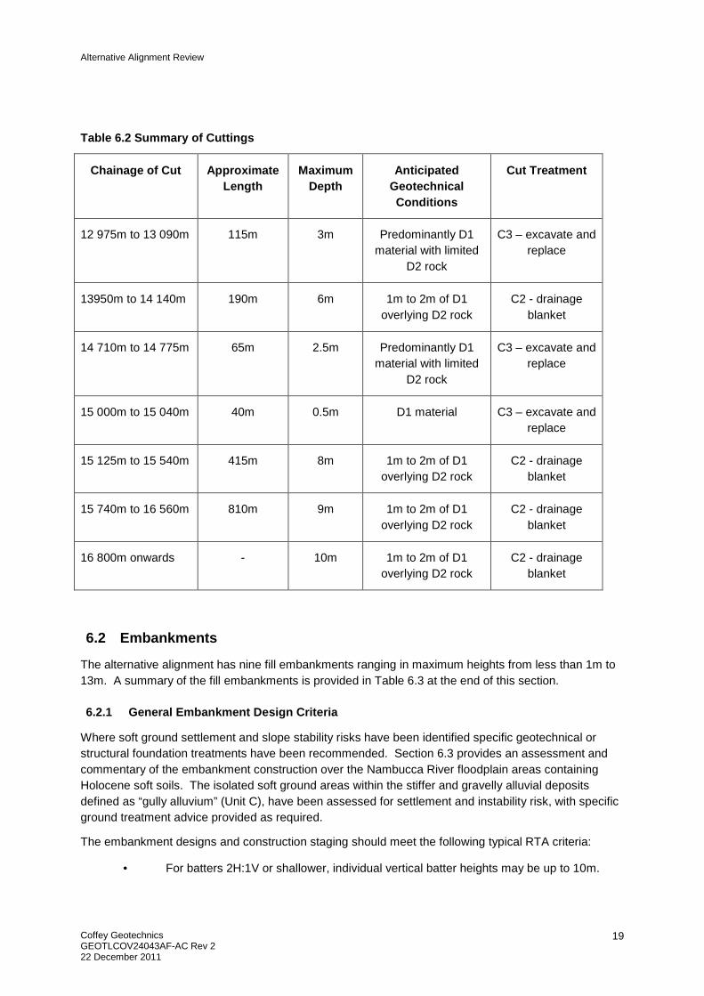
Table 6.2 provides a summary of the cut details. The assessed cut treatment has been evaluated from the cut treatment recommended for cuts along the approved alignment with similar geotechnical conditions.
Alternative Alignment Review
Coffey Geotechnics GEOTLCOV24043AF-AC Rev 2 22 December 2011
19
Table 6.2 Summary of Cuttings
Chainage of Cut Approximate Length
Maximum Depth
Anticipated Geotechnical Conditions
Cut Treatment
12 975m to 13 090m 115m 3m Predominantly D1 material with limited
D2 rock
C3 – excavate and replace
13950m to 14 140m 190m 6m 1m to 2m of D1 overlying D2 rock
C2 - drainage blanket
14 710m to 14 775m 65m 2.5m Predominantly D1 material with limited
D2 rock
C3 – excavate and replace
15 000m to 15 040m 40m 0.5m D1 material C3 – excavate and replace
15 125m to 15 540m 415m 8m 1m to 2m of D1 overlying D2 rock
C2 - drainage blanket
15 740m to 16 560m 810m 9m 1m to 2m of D1 overlying D2 rock
C2 - drainage blanket
16 800m onwards - 10m 1m to 2m of D1 overlying D2 rock
C2 - drainage blanket
6.2 Embankments
The alternative alignment has nine fill embankments ranging in maximum heights from less than 1m to 13m. A summary of the fill embankments is provided in Table 6.3 at the end of this section.
6.2.1 General Embankment Design Criteria
Where soft ground settlement and slope stability risks have been identified specific geotechnical or structural foundation treatments have been recommended. Section 6.3 provides an assessment and commentary of the embankment construction over the Nambucca River floodplain areas containing Holocene soft soils. The isolated soft ground areas within the stiffer and gravelly alluvial deposits defined as “gully alluvium” (Unit C), have been assessed for settlement and instability risk, with specific ground treatment advice provided as required.
The embankment designs and construction staging should meet the following typical RTA criteria:
• For batters 2H:1V or shallower, individual vertical batter heights may be up to 10m.
Alternative Alignment Review
Coffey Geotechnics GEOTLCOV24043AF-AC Rev 2 22 December 2011
20
• Minimum bench width of 4m.
• Access to the final batter slopes must be available for maintenance plant and equipment.
• Globally and locally stable with no foreseeable possibility of a failure involving the whole embankment or a major part of the embankment.
• Main carriageway and ramp embankments above compressible foundation materials must comply with the following pavement performance criteria:
� A maximum decrease in levels of 10mm over any twelve month period.
� A maximum decrease in levels of the greater of 15mm, or 0.25% of the embankment height at carriageway centreline.
� Maximum total residual settlement of 100mm in 40years.
� Maximum change of grade, in any direction, of 0.3% over 40 years.
The design model provides for 2H:1V fill embankment batters. A bench has been provided in the model where the embankment height is over 10m high.
6.2.2 Embankment Foundation Preparation and Treatments
The following embankment foundation treatments, as specified in RTA specification R44 have been assessed as being applicable for each of the forty embankments.
• Type E1 Treatment – Loosen and Recompact;
• Type E2 Treatment – Bridging Layer;
• Type E5 Treatment – Drainage Blanket;
The use of other R44 treatments (Type E3 working platform by stabilisation and Type E4 geogrid) may be considered during construction or as part of the soft ground foundation treatments.
Type E1 Treatment – Loosen and Recompact
Following vegetation removal, topsoil stripping and the removal or treatment of unsuitable material, the stripped surface will be loosened by ripping to a depth of 300mm and then recompacted to a minimum dry density ratio of 95% standard compaction. Type E1 treatment is viewed as the standard foundation treatment for embankments not influenced by wet or soft subgrade conditions.
Type E2 Treatment – Bridging Layer
Bridging, as an embankment foundation treatment, is to provide a working platform upon which an embankment can be constructed over soft/ heaving ground and/or ground that could be considered unsuitable if excavated and removed. Bridging is typically placed by end dumping without further compaction and is traditionally a “site won” material.
RTA R44 advises that bridging can comprise either earthfill or rock fill. The thickness of a bridging layer is not specified in R44 other than a requirement for a minimum separation of 600mm between bridging and the underside of pavements. Where earthfill is to be used, the material will be a:
“Granular material with strong mechanical interlock and low sensitivity to moisture”

Alternative Alignment Review
Coffey Geotechnics GEOTLCOV24043AF-AC Rev 2 22 December 2011
21
The requirements for a rockfill include:
• The compacted rock fill layer thickness will not exceed 550mm;
• The material will be well graded with a maximum particle dimension of 350mm;
• A maximum of 10% of the material will have a particle dimension of greater that 100mm;
• The material will have a Point Load Strength Index of ≥1 MPa and a maximum Wet/Dry Strength Variation of 35%.
Areas where bridging would be suitable are broad valley floor areas such as in the northern sections of the alternative alignment that could be problematic following rain (poor trafficability) and bridging will allow for a working surface to be prepared quickly without the delays of waiting for the stripped surface to dry and be able to be compacted. Where the area is anticipated to have periodic ponded water or an elevated ground water table a drainage blanket has been recommended.
Type E5 Treatment – Drainage Blanket
Where active groundwater movement is anticipated beneath or across the proposed alignment or there is ponded water, a drainage blanket embankment foundation is recommended. A drainage blanket consists of a rock layer enclosed by a geotextile and will have the following properties:
• It will be constructed in a 300mm thick layer (+100mm/-0mm);
• 100% of the material will pass the AS 125mm sieve, with 0% to 15% passing the AS 19mm sieve, 0% to 5% passing the AS 1.18mm sieve and <0.5% passing the AS 75µm sieve (i.e. it will contain no silt or clay fines);
• The material will have a Point Load Strength Index of ≥1 MPa and a maximum Wet/Dry Strength Variation of 35%.
6.2.3 Embankment Settlement
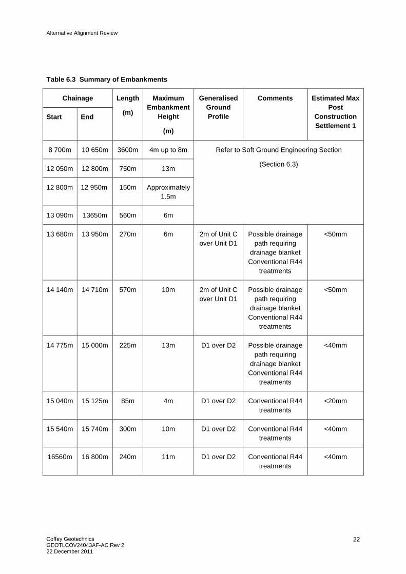
Post-construction settlement is an important consideration when planning embankment construction, as excessive total and/or differential settlements can significantly reduce the operational life of the pavement. The assessment of post-construction settlements has been carried out for the embankments using the settlements calculated for similar embankments on similar anticipated subsurface conditions on the approved alignment.
Alternative Alignment Review
Coffey Geotechnics GEOTLCOV24043AF-AC Rev 2 22 December 2011
22
Table 6.3 Summary of Embankments
Chainage Length
(m)
Maximum Embankment
Height
(m)
Generalised Ground Profile
Comments Estimated Max Post
Construction Settlement 1
Start End
8 700m 10 650m 3600m 4m up to 8m Refer to Soft Ground Engineering Section
(Section 6.3) 12 050m 12 800m 750m 13m
12 800m 12 950m 150m Approximately 1.5m
13 090m 13650m 560m 6m
13 680m 13 950m 270m 6m 2m of Unit C over Unit D1
Possible drainage path requiring
drainage blanket Conventional R44
treatments
<50mm
14 140m 14 710m 570m 10m 2m of Unit C over Unit D1
Possible drainage path requiring
drainage blanket Conventional R44
treatments
<50mm
14 775m 15 000m 225m 13m D1 over D2 Possible drainage path requiring
drainage blanket Conventional R44
treatments
<40mm
15 040m 15 125m 85m 4m D1 over D2 Conventional R44 treatments
<20mm
15 540m 15 740m 300m 10m D1 over D2 Conventional R44 treatments
<40mm
16560m 16 800m 240m 11m D1 over D2 Conventional R44 treatments
<40mm

Alternative Alignment Review
Coffey Geotechnics GEOTLCOV24043AF-AC Rev 2 22 December 2011
23
6.3 Soft Ground Engineering
6.3.1 Introduction
The alternative alignment traverses over a longer section of soft floodplain soils than the approved alignment and incorporates a bridge over Nambucca River along with four 50m wide box culverts and a number of pipe culverts.
Limited site investigations have been performed along the alternative alignment and what data exists is shown in previous reports. For the purpose of this assessment, ground conditions encountered along the preferred alignment are projected onto the proposed alignment. The projections are performed over many hundreds of metres and should be considered an indicative geological model for the proposed alignment accurate to a first approximation. Detailed site investigations along the proposed alignment may show ground conditions vary from what has been assumed.
Assessments for settlement and ground treatment for the alternative alignment are based on the assessments done for the approved alignment and presented in our previous interpretation reports GEOTLCOV24043AD-Early works (dated 4 February 2011) and GEOTLCOV24043AB-BZ Warrell Creek to Nambucca Heads (dated 19July 2011). Coffey has had significant experience in providing the geotechnical design of soft ground engineering works on the Ballina Bypass and the Kempsey Bypass Alliance projects. The personnel who provided the geotechnical design on these projects have undertaken the assessment for the Early Works Study that included assessment of soft ground treatment options in the Nambucca River floodplain using the geotechnical information referred to in Section 3.3.
6.3.2 Locations of soft ground
Locations of soft ground are summarised in Table 6.4 along with embankment fill thicknesses and estimated depths of soft soil.
Table 6.4. Summary of Soft Ground Locations
Chainage Fill Thickness (m) Depth soft soil (m) Comment
8700 to 9100 2 to 3 11 to 5 Box culverts at Ch8960
9100 to 9620 4.0 17 Box culverts at Ch9220
9620 to 10650 3.1 to 6.7 20 Box culverts at Ch9730 and Ch 10220. Also
includes bridge approach
12050 to 12800 11.5 to 1.3 15 Bridge approach
12800 to 12950 1.5 15 to 0
13100 to 13650 1.4 to 4.8 4 Box culvert at Ch13200

Alternative Alignment Review
Coffey Geotechnics GEOTLCOV24043AF-AC Rev 2 22 December 2011
24
6.3.3 Settlement design criteria
Settlement design criteria adopted in our previous interpretation report have been adopted for this study. Table 6.5 details the design criteria.

Alternative Alignment Review
Coffey Geotechnics GEOTLCOV24043AF-AC Rev 2 22 December 2011
25
Table 6.5 Summary of Proposed Post-construction Settlement Criteria for Preliminary Design
Zone
Permanent Pavement Staged Pavement
Notes Plain Concrete
Pavement Granular Pavement
Total Post Construction Settlement (not including internal settlement)
1. Abutment zone
50mm in 40yrs 50mm in 40yrs
1. Settlement additional to abutment structure
2. Settlement taken at terminal slab anchor point
3. Minor corrections may be required before 10 years
2. Transition Zone
Increasing at not more than 0.3% grade from
Zone 1 to Zone 3
Increasing at not more than 0.5% grade from
Zone 1 to Zone 3
4. Length of transition zone determined by differential settlement between Zones 1 and 3, but need to continue until estimated settlement for untreated embankment is less than 200mm in 10 years
3. Low embankment
zone 100mm in 40 years
Depends on length of approach and 0.5%
grade. Aim for 200mm in 10 years.
5. Overlay sooner if settlement causes safety concern
Differential Settlement
Zones 2 and 3 Rmin = 1,600m in 40
years Rmin = 1,000m in 10
years
6. Trigger level for review will depend on actual pavement and ride quality performance
We have assumed that concrete pavement will be adopted for the purpose of this assessment.
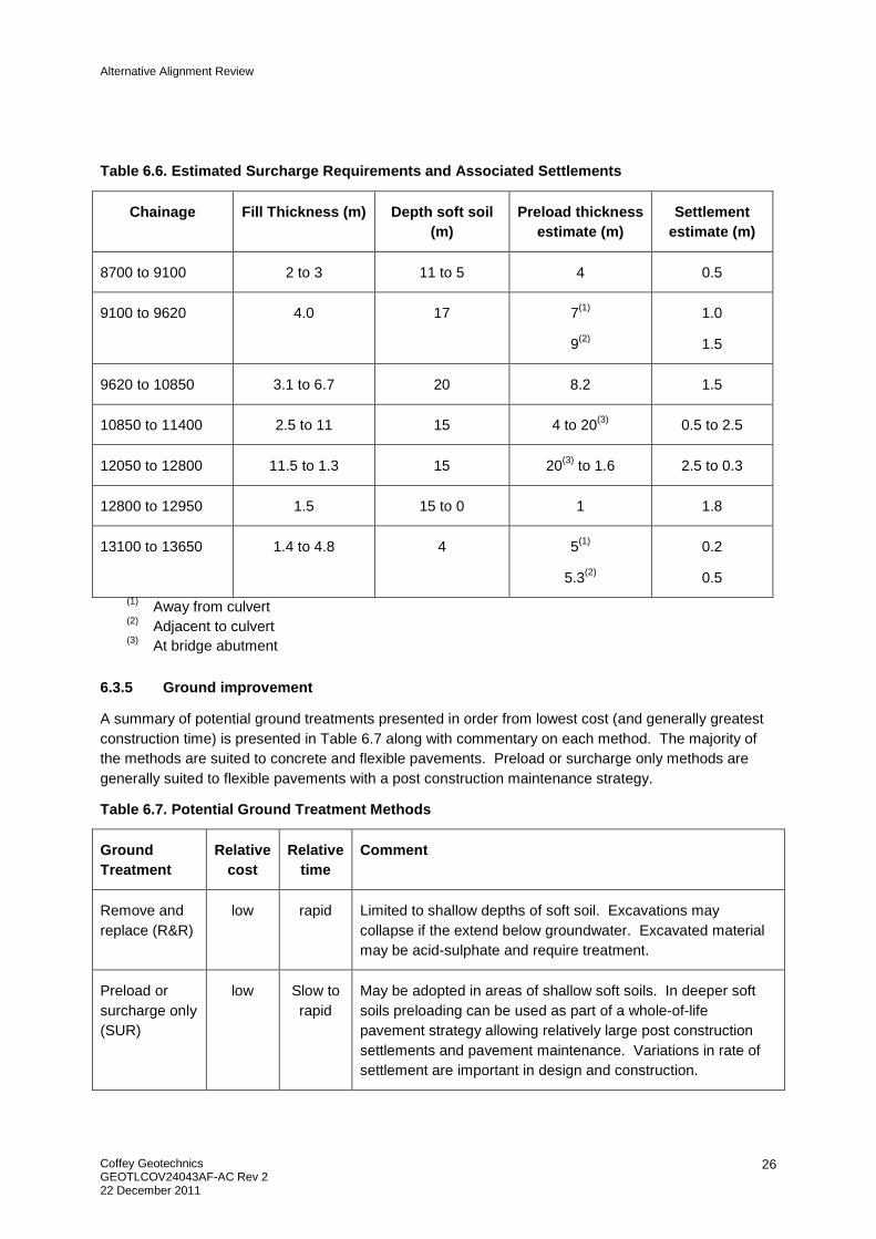
6.3.4 Surcharge and settlement estimates
Estimates of surcharge requirements and associated settlement (with wick drains or surcharge only) are presented in Table 6.6.
Alternative Alignment Review
Coffey Geotechnics GEOTLCOV24043AF-AC Rev 2 22 December 2011
26
Table 6.6. Estimated Surcharge Requirements and Associated Settlements
Chainage Fill Thickness (m) Depth soft soil (m)
Preload thickness estimate (m)
Settlement estimate (m)
8700 to 9100 2 to 3 11 to 5 4 0.5
9100 to 9620 4.0 17 7(1)
9(2)
1.0
1.5
9620 to 10850 3.1 to 6.7 20 8.2 1.5
10850 to 11400 2.5 to 11 15 4 to 20(3) 0.5 to 2.5
12050 to 12800 11.5 to 1.3 15 20(3) to 1.6 2.5 to 0.3
12800 to 12950 1.5 15 to 0 1 1.8
13100 to 13650 1.4 to 4.8 4 5(1)
5.3(2)
0.2
0.5
(1) Away from culvert (2) Adjacent to culvert (3) At bridge abutment
6.3.5 Ground improvement
A summary of potential ground treatments presented in order from lowest cost (and generally greatest construction time) is presented in Table 6.7 along with commentary on each method. The majority of the methods are suited to concrete and flexible pavements. Preload or surcharge only methods are generally suited to flexible pavements with a post construction maintenance strategy.
Table 6.7. Potential Ground Treatment Methods
Ground Treatment
Relative cost
Relative time
Comment
Remove and replace (R&R)
low rapid Limited to shallow depths of soft soil. Excavations may collapse if the extend below groundwater. Excavated material may be acid-sulphate and require treatment.
Preload or surcharge only (SUR)
low Slow to rapid
May be adopted in areas of shallow soft soils. In deeper soft soils preloading can be used as part of a whole-of-life pavement strategy allowing relatively large post construction settlements and pavement maintenance. Variations in rate of settlement are important in design and construction.

Alternative Alignment Review
Coffey Geotechnics GEOTLCOV24043AF-AC Rev 2 22 December 2011
27
Ground Treatment
Relative cost
Relative time
Comment
Surcharge and wick drains (SWD)
Low to medium
Slow to Medium
Used where post construction settlements using preloading are too large. Wick drains speed up the consolidation process. The most cost effective approach is multi-staged construction that optimises spacing of wick drains, volumes of surcharge, stabilisation measures and construction time. Construction in a single stage can result in wide stability berms (up to 30m) and multiple layers of structural geofabric. Allowance for treatment of extruded groundwater may be required. Large settlements can occur and may affect adjacent structures.
Vacuum consolidation (VC)
Medium Medium Either the membraneless (Beaudrain) or membrane (Menard) version could be adopted. Limited (low) vacuum pressures could be developed due to relatively high permeability soils and the presence of sand lenses resulting in low efficiency. Large volumes of groundwater can be extracted. If the groundwater requires treatment then large sedimentation ponds may be necessary. However, VC may allow embankments to be constructed in a single stage.
Electro-osmosis (EO)
Medium Medium Suitable for ground that has low electrical conductivity. Probably not suitable for coastal high conductivity saline soils along the Pacific Highway.
Dry or Wet Soil Mixing (DSM / WSM)
Medium Rapid Dry cement or cement-soil slurry is mixed into the ground forming semi-rigid inclusions. Can be designed to achieve small settlements and is suited to works near existing structures such as the existing bridge over Warrell Creek. The dry method is suited to embankments up to 6m in height and soft soils to 15m depth. The wet method is suited to embankments in excess of 6m in height and can be installed to greater depth than the dry method. Construction platforms ranging in thickness from 0.5m to 1.5m are required to support the rigs.
Dynamic Replacement (DR)
Medium Medium to Rapid
Replaces soft soil with granular material though dropping a heavy weight from a large height. Column diameters of about 2.5m are formed and often constructed at 5m spacings. Suited to soft soil depths of 5m to 6m. DR may not penetrate through greater depths of soft soil. There are very limited areas where the soft soil is shallow enough to consider the use of DR.
Dry or wet vibro-replacement stone columns
Medium Medium Suited to high embankments and soft soils ranging from 10m to 20m depth. Typically reduces settlement by 50% compared with surcharge and wick drains and enhances embankment stability. Significant settlements can still occur and may not be

Alternative Alignment Review
Coffey Geotechnics GEOTLCOV24043AF-AC Rev 2 22 December 2011
28
Ground Treatment
Relative cost
Relative time
Comment
with surcharge (SC)
applicable adjacent to existing structures. Less surcharge is required than a wick drain only treatment. The dry method has been used to limit water treatment costs in areas where spoil water requires treatment.
Rigid inclusions such as Concrete Injected Columns (CIC) or Piled Embankment (PE)
High Rapid Suited to high embankments, deep soft soils, rapid construction or where settlements need to be kept to small values. May be reinforced or unreinforced with low strength grout. If the columns require reinforcement then durability issues can increase the cost of grout mix design.
Light or ultra- light weight fill (LWF)
Medium to high
Rapid Can be used to reduce settlement by reducing load. Lightweight fills include bottom ash, foamed concrete and rubber tyre bundles. Ultra light weight fill comprises expanded polystyrene blocks (EPB). The strength and stiffness of EPB can be compromised if it comes in contact with petrochemicals and needs protecting with a membrane or other barrier. EPB is lighter than water and measures against floating during flooding need to be implemented. Light and ultra light weight fills are also used as contingency measures to speed up construction where consolidation type ground treatments are taking longer than anticipated or settling more than anticipated.
The suitability of various types of ground improvement method is assessed in Table 6.9. Light weight fill or ultra light weight fill are not considered suitable as a primary treatment but should be considered as contingency measures during construction.
For the purpose of this assessment ground treatments have been selected for use in various areas and these are described in the following sections.
6.3.5.1 Ch 8 700 to Ch 9 100
This area can potentially be preloaded without the use of wick drains, however the risk of time delays or greater settlement than desired increases as the depth of soft soil increases. Preload only is recommended where the depth of soft clay is 8m or less and wick drains are recommended where the depth of soft soil exceeds 8m.

Alternative Alignment Review
Coffey Geotechnics GEOTLCOV24043AF-AC Rev 2 22 December 2011
29
6.3.5.2 Ch 9 100 to Ch 9 620
Away from box culverts, the height of embankments and depth of soft clay will require wick drains to be adopted. A 1.5m wick drain spacing in a triangular pattern is recommended. A 10m wide by 3m high stability berm will be required along with one layer of 600kN/m structural geofabric. The height of preload will increase in the 30m approach to the box culvert from 7m to 9m.
The box culvert is recommended to be supported on driven piles or concrete injected columns. The spacing of the piles is likely to be 2m by 2m square and the piles will be driven to at least 20m depth.
6.3.5.3 Ch 9 620 to Ch 10 600
We recommend adoption of wick drains in this section to reduce risks of time delay and excessive settlements associated with the deep deposits of soft clay even though the embankments are not high. A 1.5m wick drain spacing in a triangular pattern is recommended. A 10m wide by 3m high stability berm will be required along with one layer of 600kN/m structural geofabric.
6.3.5.4 Ch 10 600 to Ch 10 650
For the bridge approach, we recommend a 7m to 8m high surcharge with wick drains (SWD) is to be adopted. It is anticipated that the period of surcharge would be 18 months A 10m wide by 3m high stability berm will be required along with one layer of 600kN/m structural geofabric.
6.3.5.5 Ch 12 050 to Ch 12 800
A CIC supported embankment can be constructed between Ch12050 and Ch12120 at the bridge approach (Zone 1A and Zone 2A in Sketch 1 below). Surcharge with wick drains (SWD) can be adopted from Ch12120 to Ch12800 (Zone 2B in Sketch 1 below). CIC are again adopted to allow earlier access to the bridge abutment for construction than would occur for the multiple stages of construction associated with SWD.

Alternative Alignment Review
Coffey Geotechnics GEOTLCOV24043AF-AC Rev 2 22 December 2011
30
Sketch 1. Ground Treatment Zones
Indicative spacing, lengths and stabilisation measures for CIC supported embankments are presented in Table 6.8.
Table 6.8 Design Concepts for CIC Supported Embankments
Type Design Height (m)
Depth of soft soil (m)
Column / Pile spacing
Column / Pile size
Column / Pile Length (m)
Stabilisation measures
CIC 7 to12 11 to 17 1.4m c/c square
0.45m dia.
Min 5m below soft soil(1)
Reinforce columns below batter with cage comprising 4Y12 bars and 2 layers of 600kN/m ultimate strength structural geofabric (1 oriented laterally, 1 oriented longitudinally).
(1)Depends on settlement assessment of soils below CIC columns
6.3.5.6 Ch12800 to Ch12950
The embankments in this area are of the order of 1.5m to 2m high. Preloading will not be required in this section, however soft material will have to be boxed out and replaced with structural fill in order to provide sufficient support for concrete pavement. Rock fill may be required and reinforced with a layer of Triax170 geogrid.
6.3.5.7 Ch13100 to Ch13650
Preload without wick drains is likely to provide sufficient ground improvement away from box culverts in this section. Adjacent to box culverts the height of the preload increases from 4m to 5m. Surcharge with wick drains could be considered over the footprint of the box culvert and in the transitions. The

Alternative Alignment Review
Coffey Geotechnics GEOTLCOV24043AF-AC Rev 2 22 December 2011
31
height of preload could increase to 7m and this will require a 10m wide by 2m high stability berm along with a layer of 600kN/m structural geofabric.
If the risks of culvert settlement are considered to be too high then the culvert could be supported on semi-rigid or rigid ground inclusions or the soft clay could be removed and replaced with structural fill.

Alternative Alignment Review
Coffey Geotechnics GEOTLCOV24043AF-AC Rev 2 22 December 2011
32
Table 6.9 Suitability of Ground Improvement Methods
Location Design Height
(m)
Depth of soil
(m) R&R SUR SWD VC EO DR DSM WSM SC CIC PE
Ch8700 to Ch9100 2 to 3 11 to 5 X X X X X X
Ch9100 to Ch9620 4 17 X X X X X
Ch9620 to Ch10850
4 to 2.5 20 X X X X X X X X X
Ch10850 to Ch11400
2.5 to 11 15 X X X X X X
Ch 12050 to Ch12800
11.5 to 0.3 15 X X X X X X
Ch12800 to Ch12950
0.3 15 to 0 X X X X X X X X X
Ch13100 to Ch13650
3 4 X X X X X X

Alternative Alignment Review
Coffey Geotechnics GEOTLCOV24043AF-AC Rev 2 22 December 2011
33
6.4 Bridge Foundations and Construction Issues
The alternative alignment plans indicate a bridge extending from approximately Ch10 650m to 12050m.
Between Ch 10 650m and Ch 11 300m the ground conditions are assessed to comprise 20m of Holocene alluvial deposits (A1 and firm to stiff clay) overlying approximately 10m of Pleistocene alluvial deposits (Unit B2). The ground conditions can be seen to comprise approximately 15m of Holocene alluvial deposits (A1/A2) overlying 10m to 15m of Pleistocene alluvial deposits (Unit B1/B2) between Ch 11 300m and Ch 11 500m. The thickness of Unit B1 material diminishes from Ch 11 550m to 11 600m so that the Holocene alluvium deepens about 18m to 20m, reducing in thickness to 8m at Ch 12 100m. The Unit B deposits below the Unit A material are approximately reduce 8m thick at Ch 11 650m before pinching out at approximate Ch 12 050m. Unit A typically consists of soft to firm clay (Unit A1) and loose sands (Unit A2); Unit B is made up of stiff to very stiff clays (Unit B1) and medium dense to dense sands and gravels (Unit B2).
Underlying the alluvial deposits is Phyllite of varying degrees of weathering and strength is anticipated. Units D1 and D2 are anticipated to have a combined thickness of around 10m to the south of the Nambucca River. The studies for the approved alignment indicate that the thickness of Unit D1 and D2 is likely to be less on the northern side of the river where typically medium to high strength slightly weathered to fresh Phyllite is shallower gradually thinning to less than 1m at the northern bank of the river (approximate Ch 10 620m).
Based on the available geotechnical information, it is considered that driven piles, founding in the alluvial gravels (Unit B2) or extremely weathered Phyllite (Unit D1), or bored piles, founding in either Unit D2 Phyllite or better would be appropriate foundation options.
Excavations for pile caps within the alluvial deposits on the floodplain may encounter groundwater, and appropriate dewatering measures should be implemented to allow construction of the pile caps. Cofferdams would be required to allow construction of pile caps within the river bed; alternatively, an option to construct columns to the underside of the bridge superstructure could be considered.
6.5 Culverts
A number of culverts of varying sizes are proposed along the alterative alignment. It is anticipated that the culverts will provide drainage, fauna crossing or access paths beneath the proposed highway.
Coffey has been supplied with details of culvert locations, dimensions, and structure type (ie box or pipe culvert) based on flood modelling of the alternate route. Table 6 10 provides a summary of the culverts including anticipated structure type, and anticipated founding conditions interpreted from the geotechnical investigation data.

Alternative Alignment Review
Coffey Geotechnics GEOTLCOV24043AF-AC Rev 2 22 December 2011
34
Table 6.10. Summary of Culverts
Approximate Chainage
Potential Structure Type
Approximate Size
Foundation Conditions Anticipated Pile Length (m)
Foundation Treatment
Ch 8 960m Box culvert 12m long series of culverts
Approximately 9m of A1 alluvial soils overlying B1 soils
10m Driven piles or concrete injected columns. Piles to be driven to Unit B material. Ground improvement required in transition zone.
Ch 9 240m Box culvert 50m long series of culverts
Approximately 16m of A1 alluvial soils overlying B2 soils
18m Driven piles or concrete injected columns. Piles to be driven to Unit B material. Ground improvement required in transition zone
Ch 9 730m Box culvert 60m long series of culverts
Approximately 19m of A1 overlying Unit B2 soils
21m Driven piles or concrete injected columns. Piles to be driven to Unit B material. Ground improvement required in transition zone.
Ch 10 220m Box culvert 50m long series of culverts
Approximately 19m of A1 overlying Unit B2 soils
21m Driven piles or concrete injected columns. Piles to be driven to Unit B material. Ground improvement required in transition zone
Ch 12 120m Pipe 1.8m Approximately 8m of A1 overlying Unit D1
- Localised excavate and replace of soft foundation materials. Recommend oversizing the pipe such that the flow capacity is maintained following settlement of the structure..

Alternative Alignment Review
Coffey Geotechnics GEOTLCOV24043AF-AC Rev 2 22 December 2011
35
Approximate Chainage
Potential Structure Type
Approximate Size
Foundation Conditions Anticipated Pile Length (m)
Foundation Treatment
Ch 12 700m Pipe or box culvert
2.1m Approximately 13m of A1 overlying Unit D1
14m If box culvert then driven piles or concrete injected columns to unit D1. If pipe then recommend oversizing the pipe such that the flow capacity is maintained following settlement of the structure.
Ch 13 200m Box culvert 2.7m x 1.5m Approximately 3m of A1 overlying Unit D1
- Slab footing with localised excavation and replace of unsuitable founding material
Ch 13 620m Box culvert 2 culverts of 2.7m x 1.5m
D1 material - Slab footing with localised excavation and replace of unsuitable founding material
Ch 13 840m Pipe 1.5m Approximately 2m of C overlying D1
- Slab footing with localised excavation and replace of unsuitable founding material
Ch 14 420m Pipe 2.1m Approximately 2m of C overlying D1
- Slab footing with localised excavation and replace of unsuitable founding material
Ch 14 980m Pipe 1.05m D1 material - Slab footing with localised excavation and replace of unsuitable founding material
Ch 16 700m Pipe 1.5m D1 material - Slab footing with localised excavation and replace of unsuitable founding material
Alternative Alignment Review
Coffey Geotechnics GEOTLCOV24043AF-AC Rev 2 22 December 2011
36
Both pipe and box culverts require design settlement limits. In the case of pipe culverts, allowable settlement is controlled by the flow capacity of the pipe and the allowable differential settlement between the pipe units. Settlement limits for box culverts can be governed by flow capacity or structural capacity of the culvert due to differential settlement. The structural capacity is limited to the capacity to withstand differential settlements without substantial cracking as this would cause a long term durability problem for the culvert. Both pipe and box culverts are designed for a 100 year life.
The design requirements for pipe culverts can often be achieved by constructing the pipes just prior to pavement construction after allowing the embankments to settle. The pipes are also often over sized to compensate for predicted long term settlement. If these measures do not reduce settlement to design values then ground treatment is required.
In principle, it is possible to design ground treatments such as SWD, DSM, WSM and SC to limit settlement of the box culverts to a design value. In principle, allowing box culverts to settle 50mm or 100mm is attractive because it allows a smooth settlement transition from the culvert to the embankments to be developed. However, allowing box culverts to settle poses the following risks:
• Accurate assessment of differential settlements in three dimensions is difficult resulting in some uncertainty in the performance of the culverts; and
• Settlement of embankments on either side of the box can cause down drag forces on the sides of the culvert that result in hogging deformations. Hogging deformations can cause link slab joints and the haunches of the arch units to crack.
Further geotechnical assessment would be required before being able to recommend allowing box culverts to settle at this stage. For preliminary design we recommend that the culverts within the Nambucca River floodplain, at Chainages Ch 8 960m, Ch9 240m, Ch 9 730m, Ch 10 220m, Ch 12 700m, 13 200m and Ch 13 620m be supported on piles founded in the Unit B Pleistocene soils or the Unit D1 residual soils. Details of the structures are not available to perform preliminary design, however box culverts have been similarly supported on piles for the Ballina Bypass and some of the design details are provided below:
• 350mm square precast concrete driven piles were adopted;
• The piles were founded at least 6m into stiff Pleistocene clay;
• The piles were spaced in about a 2m by 2m grid for an embankment height of 2.5m; and
• A 0.45m thick concrete base slab was adopted.
These design details are consistent with the approved alignment. Founding the culverts on piles will cause short wave length differential settlements of the overlying pavements unless a transition between the culverts and the adjacent embankments is created using ground treatment. For embankments of 3m height or less adopting SWD or DSM transitions as discussed in Section 20.5 is recommended. The length of the transition is likely to range between 20m and 50m to control differential settlements of the pavement to design limits

Alternative Alignment Review
Coffey Geotechnics GEOTLCOV24043AF-AC Rev 2 22 December 2011
37
7 GEOTECHNICAL ISSUES - APPROVED ALIGNMENT AND ALTERNATIVE ALIGNMENT
The main geotechnical issues and differences associated with this section of the approved alignment and the alternative alignment is the extent and treatment of soft soils. Table 7.1 below provides a summary of these geotechnical issues. The approved alignment is taken as commencing at project chainage Ch 8 700m and terminating at Ch 16 200m. The alternative alignment is taken as commencing at Ch 8 700m and terminating at Ch16 934m. Details regarding the geotechnical conditions along the approved alignment are discussed in Coffey report ref GEOTLCOV24043AB-BZ dated 19 July 2011.
Table 7.1 Geotechnical Issues – Approved and Alternate Alignment
Issue Approved Alignment Alternative Alignment
Length of Alignment Requiring Soft Soil Treatment
1 600m 3 550m
Time Required for Consolidation.
Time required is dependent on depth of soft soils
Depths of Soft Soil <7m - 550m
7m to 9m 450m 900m
9m to 12m 150m 400m
15m to 17m 1000m 850m
>17m - 900m
Soft Soil Treatments Required Surcharge only 400m 950m
Surcharge + Wick Drains
1130m 2 230m
Cement Injected Columns
70m 70m
Excavate and Replace
300m
Related to the soft soil treatment is the requirement for ground improvement for culverts and pipes in the soft soil area. Based on the proposed designs provided to Coffey, we understand that there will be three large box culverts in the approved alignment and four large box culverts, one smaller box culvert and four pipes in the soft soil areas for the alternative alignment. The areas around these structures require treatment to reduce the impact of ground settlement on the performance and integrity of these structures.

Alternative Alignment Review
Coffey Geotechnics GEOTLCOV24043AF-AC Rev 2 22 December 2011
38
In addition to the soft soil issues, there are issues related to the extent of cuts and the material extracted from them. The approved alignment has more cuts than the alternative resulting in more excavated material being generated. As the proposed cuts in the approved alignment are deeper, it is anticipated that a greater amount of less weathered Phyllite (Unit D2) will be excavated than compared to the alternative alignment. The less weathered Phyliite is of greater engineering utility than the more weathered D2 material. The cuttings on the alternative alignment are primarily through D1 material.
8 CONDITIONS OF THIS REPORT
This report has been based on details provided for the alternative alignment as a 5 December 2011. The geological conditions discussed in this report have been based on information collected for the approved alignment, with inferences drawn based on site observations from publicly accessible land. The geotechnical conditions and recommendations provided in this report are for the purposes of a technical review only and not detailed design.
For and on behalf of Coffey Geotechnics Pty Ltd
Paran Moyes
Associate Geotechnical Engineer
Coffey Geotechnics Pty Ltd ABN 93 056 929 483
As a client of Coffey you should know that site subsurface conditions cause more constructionproblems than any other factor. These notes have been prepared by Coffey to help youinterpret and understand the limitations of your report.
Your report is based on project specific criteria
Your report has been developed on the basis of yourunique project specific requirements as understoodby Coffey and applies only to the site investigated.Project criteria typically include the general nature ofthe project; its size and configuration; the location ofany structures on the site; other site improvements;the presence of underground utilities; and the additionalrisk imposed by scope-of-service limitations imposedby the client. Your report should not be used if thereare any changes to the project without first askingCoffey to assess how factors that changed subsequentto the date of the report affect the report'srecommendations. Coffey cannot accept responsibilityfor problems that may occur due to changed factorsif they are not consulted.
Subsurface conditions can change
Subsurface conditions are created by natural processesand the activity of man. For example, water levelscan vary with time, fill may be placed on a site andpollutants may migrate with time. Because a reportis based on conditions which existed at the time ofsubsurface exploration, decisions should not be basedon a report whose adequacy may have been affectedby time. Consult Coffey to be advised how time mayhave impacted on the project.
Interpretation of factual data
Site assessment identifies actual subsurface conditionsonly at those points where samples are taken andwhen they are taken. Data derived from literatureand external data source review, sampling and subsequent laboratory testing are interpreted bygeologists, engineers or scientists to provide anopinion about overall site conditions, their likelyimpact on the proposed development and recommendedactions. Actual conditions may differ from those inferredto exist, because no professional, no matter howqualified, can reveal what is hidden by
Your report will only givepreliminary recommendationsYour report is based on the assumption that thesite conditions as revealed through selectivepoint sampling are indicative of actual conditionsthroughout an area. This assumption cannot besubstantiated until project implementation hascommenced and therefore your report recommendationscan only be regarded as preliminary. Only Coffey,who prepared the report, is fully familiar with thebackground information needed to assess whetheror not the report's recommendations are valid andwhether or not changes should be considered asthe project develops. If another party undertakesthe implementation of the recommendations of thisreport there is a risk that the report will be misinterpretedand Coffey cannot be held responsible for suchmisinterpretation.
earth, rock and time. The actual interface betweenmaterials may be far more gradual or abrupt thanassumed based on the facts obtained. Nothing canbe done to change the actual site conditions whichexist, but steps can be taken to reduce the impact ofunexpected conditions. For this reason, ownersshould retain the services of Coffey through thedevelopment stage, to identify variances, conductadditional tests if required, and recommend solutionsto problems encountered on site.
Your report is prepared forspecific purposes and personsTo avoid misuse of the information contained in yourreport it is recommended that you confer with Coffeybefore passing your report on to another party whomay not be familiar with the background and thepurpose of the report. Your report should not beapplied to any project other than that originallyspecified at the time the report was issued.
Important information about your Coffey Report

* For further information on this aspect reference should bemade to "Guidelines for the Provision of Geotechnicalinformation in Construction Contracts" published by theInstitution of Engineers Australia, National headquarters,Canberra, 1987.
Interpretation by other design professionals
Costly problems can occur when other design professionals develop their plans based on misinterpretationsof a report. To help avoid misinterpretations, retainCoffey to work with other project design professionalswho are affected by the report. Have Coffey explainthe report implications to design professionals affectedby them and then review plans and specificationsproduced to see how they incorporate the reportfindings.
Data should not be separated from the report*
The report as a whole presents the findings of the siteassessment and the report should not be copied inpart or altered in any way.
Logs, figures, drawings, etc. are customarily includedin our reports and are developed by scientists,engineers or geologists based on their interpretationof field logs (assembled by field personnel) andlaboratory evaluation of field samples. These logs etc.should not under any circumstances be redrawn forinclusion in other documents or separated from thereport in any way.
Geoenvironmental concerns are not at issue
Your report is not likely to relate any findings,conclusions, or recommendations about the potentialfor hazardous materials existing at the site unlessspecifically required to do so by the client. Specialistequipment, techniques, and personnel are used toperform a geoenvironmental assessment.Contamination can create major health, safety andenvironmental risks. If you have no information aboutthe potential for your site to be contaminated or createan environmental hazard, you are advised to contactCoffey for information relating to geoenvironmentalissues.
Rely on Coffey for additional assistance
Coffey is familiar with a variety of techniques andapproaches that can be used to help reduce risks forall parties to a project, from design to construction. Itis common that not all approaches will be necessarilydealt with in your site assessment report due toconcepts proposed at that time. As the projectprogresses through design towards construction,speak with Coffey to develop alternative approachesto problems that may be of genuine benefit both intime and cost.
Responsibility
Reporting relies on interpretation of factual informationbased on judgement and opinion and has a level ofuncertainty attached to it, which is far less exact thanthe design disciplines. This has often resulted in claimsbeing lodged against consultants, which are unfounded.To help prevent this problem, a number of clauseshave been developed for use in contracts, reports andother documents. Responsibility clauses do not transferappropriate liabilities from Coffey to other parties butare included to identify where Coffey's responsibilitiesbegin and end. Their use is intended to help all partiesinvolved to recognise their individual responsibilities.Read all documents from Coffey closely and do nothesitate to ask any questions you may have.
Coffey Geotechnics Pty Ltd ABN 93 056 929 483
Important information about your Coffey Report

Appendix A Site Plans

CS15CS15
CS15
CS15
CS15
TP1326TP1326
TP1326
TP1326
TP1326
TP1325TP1325
TP1325
TP1325
TP1325
TP1321TP1321
TP1321
TP1321
TP1321
GC-20GC-20
GC-20
GC-20
GC-20
GC-19GC-19
GC-19
GC-19
GC-19
GC-17GC-17
GC-17
GC-17
GC-17
CPT1206CPT1206
CPT1206
CPT1206
CPT1206
CPT1205CPT1205
CPT1205
CPT1205
CPT1205
CPT1204CPT1204
CPT1204
CPT1204
CPT1204
CPT1203CPT1203
CPT1203
CPT1203
CPT1203
BH1114BH1114
BH1114
BH1114
BH1114
BH1113BH1113
BH1113
BH1113
BH1113
1TP261TP26
1TP26
1TP26
1TP26
1CPT181CPT18
1CPT18
1CPT18
1CPT18
1CPT171CPT17
1CPT17
1CPT17
1CPT17
1CPT161CPT16
1CPT16
1CPT16
1CPT16
1BH291BH29
1BH29
1BH29
1BH29
PP
PP
AA
AA
CC
CC
I I
IIFF
FF
I I
IICC
CC
HH
HH
I I
IIGG
GG
HH
HH
WW
WW
AA
AA
YY
YY
P
A
C
I
F
I
C
H
I
G
H
W
A
Y
PP
PP
AA
AACC
CC
I I
IIF F
FFI I
IIC C
CC
HH
HH
I I
IIGG
GG
HH
HH
WW
WW
AA
AAYY
YY
P
A
C
I
F
IC
H
IG
H
W
A
Y
P P
PP
A A
AA
C C
CC
I I
II
F F
FF
I I
II
C C
CC
H H
HH
I I
II
G G
GG
H H
HH
W W
WW
A A
AA
Y Y
YY
PA
CIF
IC
H
IG
HW
AY
LEGEND
BOREHOLE LOCATIONS
LARGE DIAMETER BOREHOLE LOCATIONS
BOREHOLE LOCATION WITH STANDPIPE PIEZOMETER
TEST PIT (BACKHOE/SMALL EXCAVATOR) LOCATIONS
LARGE EXCAVATOR PIT LOCATIONS
CPT LOCATIONS
SEISMIC LINES
CHAINAGE
EXTENT OF GULLY ALLUVIUM
EXTENT OF ALLUVIUM
DRAINAGE CHANNEL
BH
LDBH
TP
EP
CPT
BOREHOLE LOCATIONS
BOREHOLE LOCATION WITH STANDPIPE PIEZOMETER
TEST PIT LOCATIONS
CPT LOCATIONS
ALTERNATIVE ALIGNMENT
WET AREA
GRAVEL PIT
SOFT SOILS TREATMENT
SL
BH*
BH
TP
CPT
BH*
5000
CURRENT INVESTIGATION (SYMBOLS) PREVIOUS INVESTIGATION (SYMBOLS)
description
drawn
approved
date
project no:
drawn
approved
date
scale
project:
title:
client:
original
size
PACIFIC HIGHWAY UPGRADE
WARRELL CREEK TO URUNGA
NAMBUCCA RIVER ALTERNATIVE CROSSING TECHNICAL REVIEW
GEOTECHNICAL ASSESSMENT
A3
drawing no:
ROADS AND TRAFFIC AUTHORITY, NSW
GEOTLCOV24043AF
CJP / AW
CJP
07 / 12 / 11
PL
OT
D
AT
E: 7
/3
0/2
01
1 1
2:3
0 P
M D
WG
F
IL
E: F
:\G
EO
TE
CH
NIC
S\1
.P
RO
JE
CT
S\G
EO
TL
CO
V2
40
\G
EO
TL
CO
V2
40
43
AB
W
AR
RE
LL
C
RE
EK
T
O U
RU
NG
A\F
IG
UR
ES
\G
EO
TL
CO
V2
40
43
AF
_F
IG
UR
ES
A
1-A
7.D
WG
revision
FIGURE A1
1:5000 SITE PLAN - SHEET 1 OF 7
COORDINATE SYSTEM: MGA ZONE 56
HEIGHT DATUM: A.H.D.
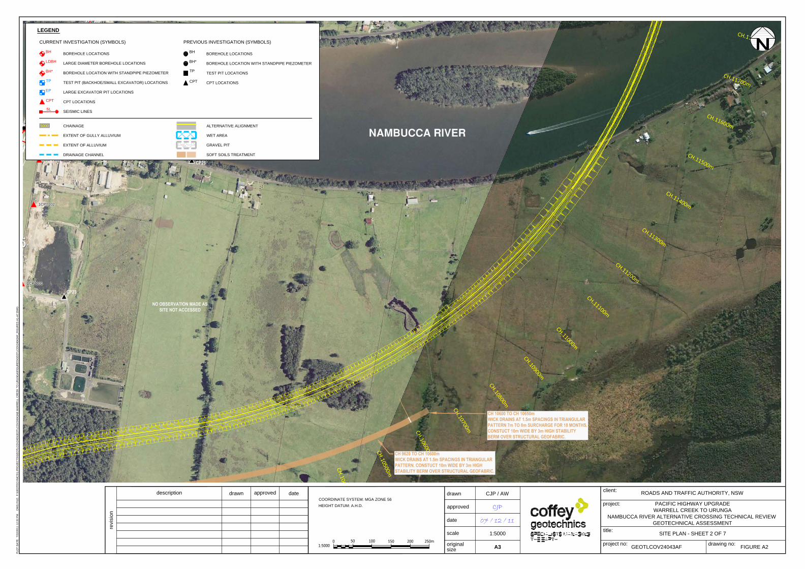
CS110CS110
CS110
CS110
CS110
GC-15GC-15
GC-15
GC-15
GC-15
GC-14GC-14
GC-14
GC-14
GC-14
BH1117BH1117
BH1117
BH1117
BH1117
BH1116BH1116
BH1116
BH1116
BH1116
1CPT341CPT34
1CPT34
1CPT34
1CPT34
1CPT311CPT31
1CPT31
1CPT31
1CPT31
1CPT291CPT29
1CPT29
1CPT29
1CPT29
1CPT281CPT28
1CPT28
1CPT28
1CPT28
1CPT271CPT27
1CPT27
1CPT27
1CPT27
1CPT1031CPT103
1CPT103
1CPT103
1CPT103
1CPT1021CPT102
1CPT102
1CPT102
1CPT102
1CPT1011CPT101
1CPT101
1CPT101
1CPT101
1BH401BH40
1BH40
1BH40
1BH40
1BH391BH39
1BH39
1BH39
1BH39
1BH371BH37
1BH37
1BH37
1BH37
1BH361BH36
1BH36
1BH36
1BH36
1BH351BH35
1BH35
1BH35
1BH35
1BH341BH34
1BH34
1BH34
1BH34
1BH33*1BH33*
1BH33*
1BH33*
1BH33*
K K
KK
E E
EE
L L
LL
L L
LL
Y Y
YY
CC
C
C
LL
L
L
OO
O
O
SS
S
S
EE
E
E
K
E
LL
Y
C
L
O
S
E
GG
G
G
UU
U
U
MM
M
M
MM
M
M
AA
A
A
RR
R
R
OO
O
O
AA
A
A
DD
D
D
G
U
M
M
A
R
O
A
D
LEGEND
BOREHOLE LOCATIONS
LARGE DIAMETER BOREHOLE LOCATIONS
BOREHOLE LOCATION WITH STANDPIPE PIEZOMETER
TEST PIT (BACKHOE/SMALL EXCAVATOR) LOCATIONS
LARGE EXCAVATOR PIT LOCATIONS
CPT LOCATIONS
SEISMIC LINES
CHAINAGE
EXTENT OF GULLY ALLUVIUM
EXTENT OF ALLUVIUM
DRAINAGE CHANNEL
BH
LDBH
TP
EP
CPT
BOREHOLE LOCATIONS
BOREHOLE LOCATION WITH STANDPIPE PIEZOMETER
TEST PIT LOCATIONS
CPT LOCATIONS
ALTERNATIVE ALIGNMENT
WET AREA
GRAVEL PIT
SOFT SOILS TREATMENT
SL
BH*
BH
TP
CPT
BH*
5000
CURRENT INVESTIGATION (SYMBOLS) PREVIOUS INVESTIGATION (SYMBOLS)
description
drawn
approved
date
project no:
drawn
approved
date
scale
project:
title:
client:
original
size
PACIFIC HIGHWAY UPGRADE
WARRELL CREEK TO URUNGA
NAMBUCCA RIVER ALTERNATIVE CROSSING TECHNICAL REVIEW
GEOTECHNICAL ASSESSMENT
A3
drawing no:
ROADS AND TRAFFIC AUTHORITY, NSW
GEOTLCOV24043AF
CJP / AW
CJP
07 / 12 / 11
PL
OT
D
AT
E: 7
/3
2/2
01
1 1
2:3
2 P
M D
WG
F
IL
E: F
:\G
EO
TE
CH
NIC
S\1
.P
RO
JE
CT
S\G
EO
TL
CO
V2
40
\G
EO
TL
CO
V2
40
43
AB
W
AR
RE
LL
C
RE
EK
T
O U
RU
NG
A\F
IG
UR
ES
\G
EO
TL
CO
V2
40
43
AF
_F
IG
UR
ES
A
1-A
7.D
WG
revision
FIGURE A2
1:5000 SITE PLAN - SHEET 2 OF 7
COORDINATE SYSTEM: MGA ZONE 56
HEIGHT DATUM: A.H.D.
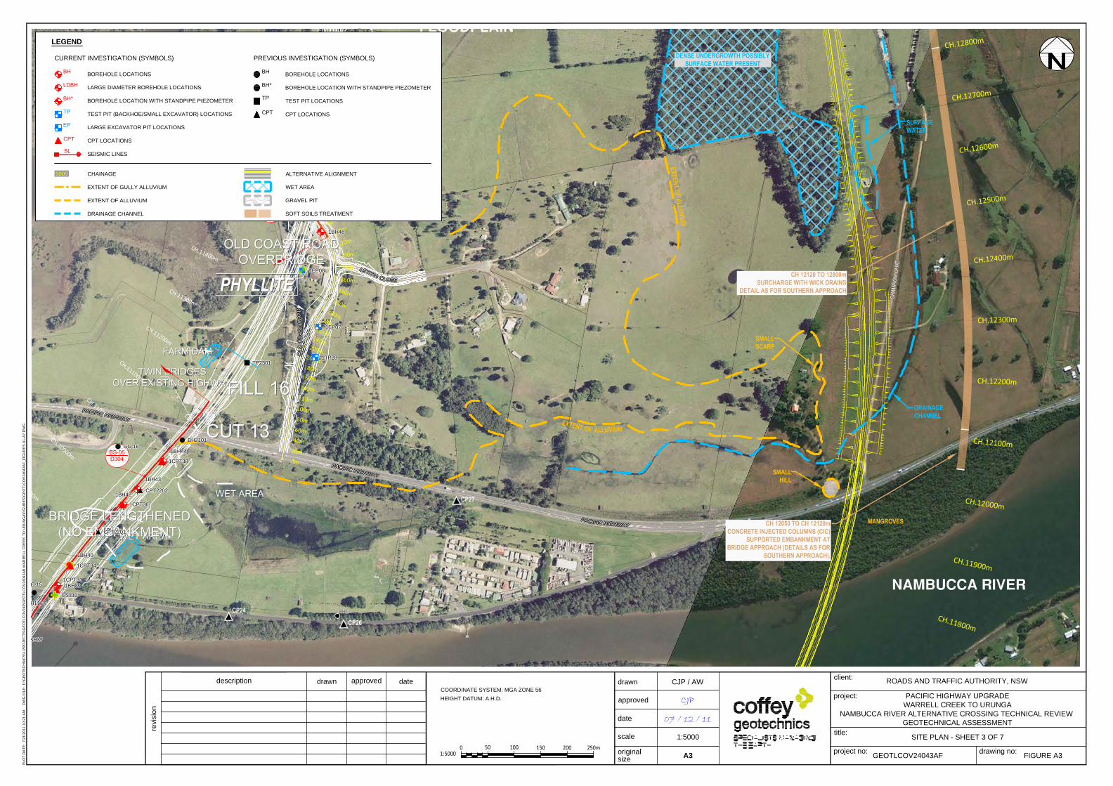
CS112CS112
CS112
CS112
CS112
CS111CS111
CS111
CS111
CS111
CS110CS110
CS110
CS110
CS110
TP2302TP2302
TP2302
TP2302
TP2302
TP2301TP2301
TP2301
TP2301
TP2301
GC-16GC-16
GC-16
GC-16
GC-16
GC-15GC-15
GC-15
GC-15
GC-15
CPT2202CPT2202
CPT2202
CPT2202
CPT2202
CPT2201CPT2201
CPT2201
CPT2201
CPT2201
BH2102BH2102
BH2102
BH2102
BH2102
BH2101BH2101
BH2101
BH2101
BH2101
BH1117BH1117
BH1117
BH1117
BH1117
1TP301TP30
1TP30
1TP30
1TP30
1TP291TP29
1TP29
1TP29
1TP29
1TP281TP28
1TP28
1TP28
1TP28
1EP091EP09
1EP09
1EP09
1EP09
1EP081EP08
1EP08
1EP08
1EP08
1EP071EP07
1EP07
1EP07
1EP07
1CPT381CPT38
1CPT38
1CPT38
1CPT38
1CPT361CPT36
1CPT36
1CPT36
1CPT36
1CPT341CPT34
1CPT34
1CPT34
1CPT34
1CPT311CPT31
1CPT31
1CPT31
1CPT31
1BH47*1BH47*
1BH47*
1BH47*
1BH47*
1BH461BH46
1BH46
1BH46
1BH46
1BH441BH44
1BH44
1BH44
1BH44
1BH431BH43
1BH43
1BH43
1BH43
1BH421BH42
1BH42
1BH42
1BH42
1BH401BH40
1BH40
1BH40
1BH40
1BH391BH39
1BH39
1BH39
1BH39
1BH371BH37
1BH37
1BH37
1BH37
1BH361BH36
1BH36
1BH36
1BH36
1BH351BH35
1BH35
1BH35
1BH35
LL
L
L
EE
E
E
TT
T
T
II
I
I
TT
T
T
II
I
I
AA
A
A
CC
C
C
LL
L
L
OO
O
O
SS
S
S
EE
E
E
L
E
T
I
T
I
A
C
L
OS
E
O O
OO
L L
LLD D
DD
C C
CC
O O
OO
A A
AA
S S
SS
T T
TT
R R
RR
O O
OO
A A
AA
D D
DD
OL
D C
OA
ST
R
O
AD
O O
OO
L L
LL
D D
DD
C C
CC
O O
OO
A A
AA
S S
SS
T T
TT
R R
RR
O O
OO
A A
AA
D D
DD
OLD
C
OA
ST
R
OA
D
PP
P
P
AA
A
A
CC
C
C
II
I
I
FF
F
F
II
I
I
CC
C
C
HH
H
H
II
I
I
GG
G
G
HH
H
H
WW
W
W
AA
A
A
YY
Y
Y
PA
C
IF
IC
H
IG
H
W
A
Y
PP
P
P
AA
A
A
CC
C
C
II
I
I
FF
F
F
II
I
I
CC
C
C
HH
H
H
II
I
I
GG
G
G
HH
H
H
WW
W
W
AA
A
A
YY
Y
Y
P
A
C
IF
IC
H
IG
H
W
A
Y
PP
P
P
AA
A
A
CC
C
C
II
I
I
FF
F
F
II
I
I
CC
C
C
HH
H
H
II
I
I
GG
G
G
HH
H
H
WW
W
W
AA
A
A
YY
Y
Y
P
A
C
I
FIC
HIG
HW
AY
LEGEND
BOREHOLE LOCATIONS
LARGE DIAMETER BOREHOLE LOCATIONS
BOREHOLE LOCATION WITH STANDPIPE PIEZOMETER
TEST PIT (BACKHOE/SMALL EXCAVATOR) LOCATIONS
LARGE EXCAVATOR PIT LOCATIONS
CPT LOCATIONS
SEISMIC LINES
CHAINAGE
EXTENT OF GULLY ALLUVIUM
EXTENT OF ALLUVIUM
DRAINAGE CHANNEL
BH
LDBH
TP
EP
CPT
BOREHOLE LOCATIONS
BOREHOLE LOCATION WITH STANDPIPE PIEZOMETER
TEST PIT LOCATIONS
CPT LOCATIONS
ALTERNATIVE ALIGNMENT
WET AREA
GRAVEL PIT
SOFT SOILS TREATMENT
SL
BH*
BH
TP
CPT
BH*
5000
CURRENT INVESTIGATION (SYMBOLS) PREVIOUS INVESTIGATION (SYMBOLS)
description
drawn
approved
date
project no:
drawn
approved
date
scale
project:
title:
client:
original
size
PACIFIC HIGHWAY UPGRADE
WARRELL CREEK TO URUNGA
NAMBUCCA RIVER ALTERNATIVE CROSSING TECHNICAL REVIEW
GEOTECHNICAL ASSESSMENT
A3
drawing no:
ROADS AND TRAFFIC AUTHORITY, NSW
GEOTLCOV24043AF
CJP / AW
CJP
07 / 12 / 11
PL
OT
D
AT
E: 7
/2
1/2
01
1 1
0:2
1 A
M D
WG
F
IL
E: F
:\G
EO
TE
CH
NIC
S\1
.P
RO
JE
CT
S\G
EO
TL
CO
V2
40
\G
EO
TL
CO
V2
40
43
AB
W
AR
RE
LL
C
RE
EK
T
O U
RU
NG
A\F
IG
UR
ES
\G
EO
TL
CO
V2
40
43
AF
_F
IG
UR
ES
A
1-A
7.D
WG
revision
FIGURE A3
1:5000 SITE PLAN - SHEET 3 OF 7
COORDINATE SYSTEM: MGA ZONE 56
HEIGHT DATUM: A.H.D.
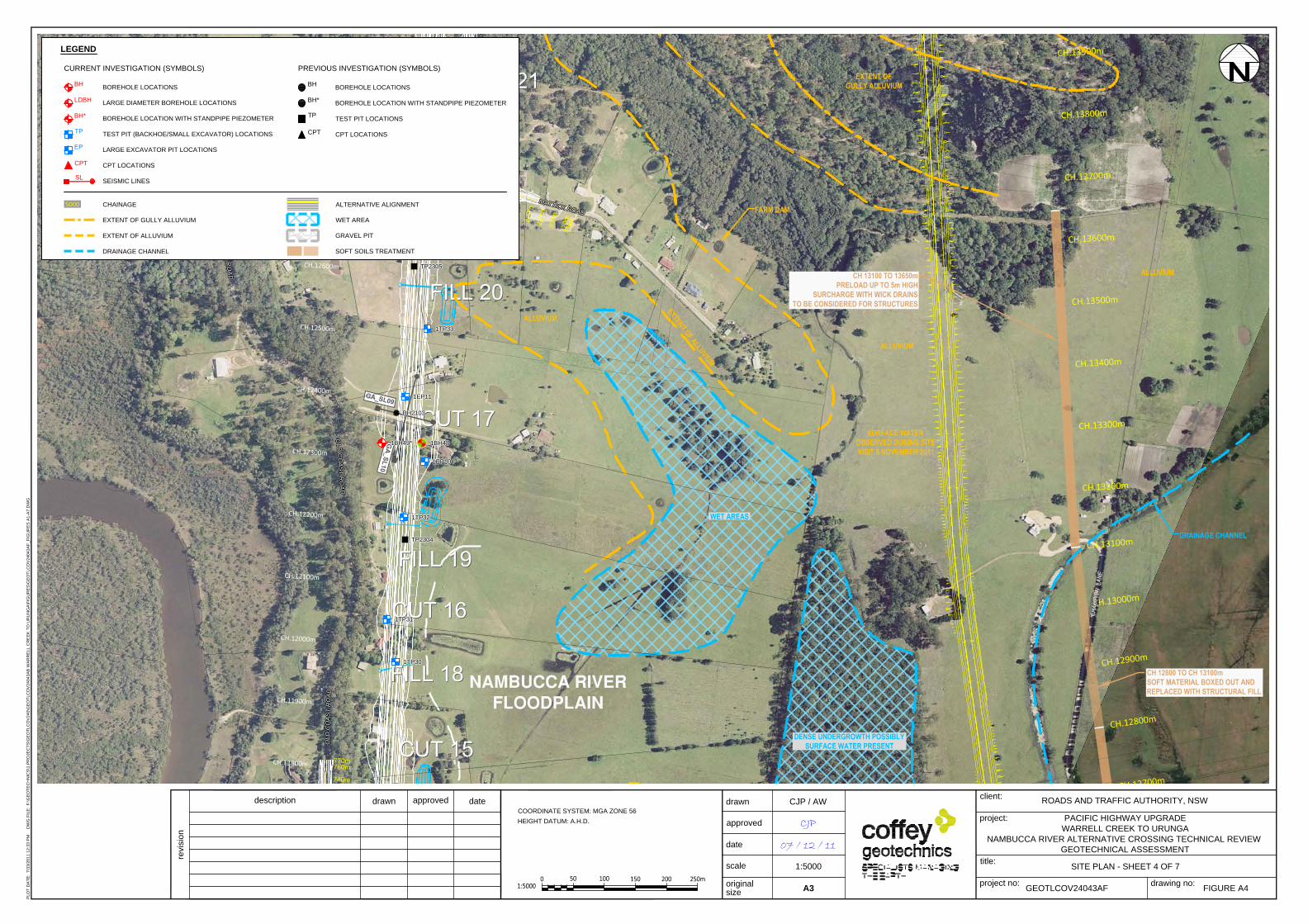
TP2305TP2305
TP2305
TP2305
TP2305
TP2304TP2304
TP2304
TP2304
TP2304
TP2302TP2302
TP2302
TP2302
TP2302
BH2104BH2104
BH2104
BH2104
BH2104
BH2103BH2103
BH2103
BH2103
BH2103
1TP371TP37
1TP37
1TP37
1TP37
1TP361TP36
1TP36
1TP36
1TP36
1TP351TP35
1TP35
1TP35
1TP35
1TP341TP34
1TP34
1TP34
1TP34
1TP331TP33
1TP33
1TP33
1TP33
1TP321TP32
1TP32
1TP32
1TP32
1TP311TP31
1TP31
1TP31
1TP31
1TP301TP30
1TP30
1TP30
1TP30
1TP291TP29
1TP29
1TP29
1TP29
1EP151EP15
1EP15
1EP15
1EP15
1EP141EP14
1EP14
1EP14
1EP14
1EP131EP13
1EP13
1EP13
1EP13
1EP121EP12
1EP12
1EP12
1EP12
1EP111EP11
1EP11
1EP11
1EP11
1EP101EP10
1EP10
1EP10
1EP10
1BH521BH52
1BH52
1BH52
1BH52
1BH51*1BH51*
1BH51*
1BH51*
1BH51*
1BH501BH50
1BH50
1BH50
1BH50
1BH49*1BH49*
1BH49*
1BH49*
1BH49* 1BH481BH48
1BH48
1BH48
1BH48
MM
M
M
AA
A
A
TT
T
T
TT
T
T
II
I
I
CC
C
C
KK
K
K
RR
R
R
OO
O
O
AA
A
A
DD
D
D
M
A
T
T
I
C
K
R
O
A
D
O O
OO
L L
LL
D D
DD
C C
CC
O O
OO
A A
AA
S S
SS
T T
TT
R R
RR
O O
OO
A A
AA
D D
DD
OLD
C
OA
ST
R
OA
D
O O
OO
L L
LL
D D
DD
C C
CC
O O
OO
A A
AA
S S
SS
T T
TT
R R
RR
O O
OO
A A
AA
D D
DD
O
L
D C
OA
ST
R
OA
D
OO
OO
LL
LL
DD
DD
C C
CC
O O
OO
A A
AA
S S
SS
T T
TT
R R
RR
O O
OO
A A
AA
D D
DD
O
L
D
CO
AS
T R
O
A
D
O O
OO
L L
LL
D D
DD
C C
CC
O O
OO
A A
AA
S S
SS
T T
TT
R R
RR
O O
OO
A A
AA
DD
DD
OLD
C
OA
ST
R
O
AD
LEGEND
BOREHOLE LOCATIONS
LARGE DIAMETER BOREHOLE LOCATIONS
BOREHOLE LOCATION WITH STANDPIPE PIEZOMETER
TEST PIT (BACKHOE/SMALL EXCAVATOR) LOCATIONS
LARGE EXCAVATOR PIT LOCATIONS
CPT LOCATIONS
SEISMIC LINES
CHAINAGE
EXTENT OF GULLY ALLUVIUM
EXTENT OF ALLUVIUM
DRAINAGE CHANNEL
BH
LDBH
TP
EP
CPT
BOREHOLE LOCATIONS
BOREHOLE LOCATION WITH STANDPIPE PIEZOMETER
TEST PIT LOCATIONS
CPT LOCATIONS
ALTERNATIVE ALIGNMENT
WET AREA
GRAVEL PIT
SOFT SOILS TREATMENT
SL
BH*
BH
TP
CPT
BH*
5000
CURRENT INVESTIGATION (SYMBOLS) PREVIOUS INVESTIGATION (SYMBOLS)
description
drawn
approved
date
project no:
drawn
approved
date
scale
project:
title:
client:
original
size
PACIFIC HIGHWAY UPGRADE
WARRELL CREEK TO URUNGA
NAMBUCCA RIVER ALTERNATIVE CROSSING TECHNICAL REVIEW
GEOTECHNICAL ASSESSMENT
A3
drawing no:
ROADS AND TRAFFIC AUTHORITY, NSW
GEOTLCOV24043AF
CJP / AW
CJP
07 / 12 / 11
PL
OT
D
AT
E: 7
/3
3/2
01
1 1
2:3
3 P
M D
WG
F
IL
E: F
:\G
EO
TE
CH
NIC
S\1
.P
RO
JE
CT
S\G
EO
TL
CO
V2
40
\G
EO
TL
CO
V2
40
43
AB
W
AR
RE
LL
C
RE
EK
T
O U
RU
NG
A\F
IG
UR
ES
\G
EO
TL
CO
V2
40
43
AF
_F
IG
UR
ES
A
1-A
7.D
WG
revision
FIGURE A4
1:5000 SITE PLAN - SHEET 4 OF 7
COORDINATE SYSTEM: MGA ZONE 56
HEIGHT DATUM: A.H.D.
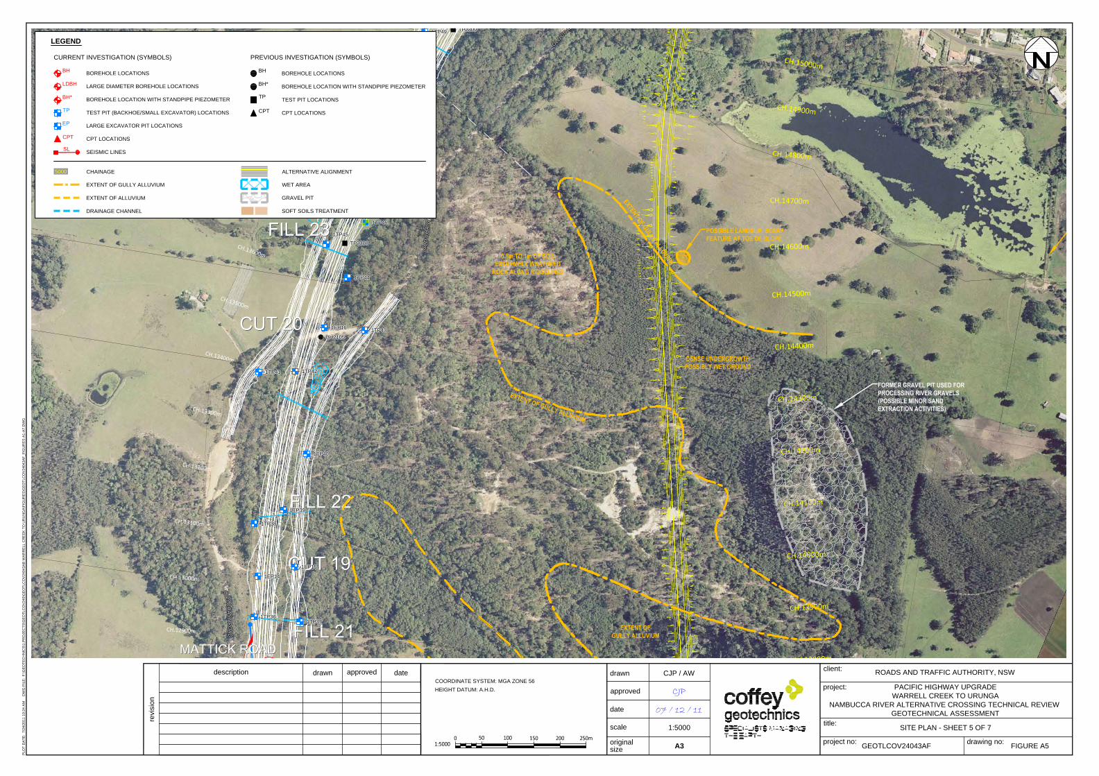
TP2309TP2309
TP2309
TP2309
TP2309
TP2308TP2308
TP2308
TP2308
TP2308
BH2106BH2106
BH2106
BH2106
BH2106
BH2105BH2105
BH2105
BH2105
BH2105
1TP491TP49
1TP49
1TP49
1TP49
1TP481TP48
1TP48
1TP48
1TP48
1TP471TP47
1TP47
1TP47
1TP47
1TP461TP46
1TP46
1TP46
1TP46
1TP451TP45
1TP45
1TP45
1TP45
1TP441TP44
1TP44
1TP44
1TP44
1TP431TP43
1TP43
1TP43
1TP43
1TP421TP42
1TP42
1TP42
1TP42
1TP411TP41
1TP41
1TP41
1TP41
1TP401TP40
1TP40
1TP40
1TP40
1TP391TP39
1TP39
1TP39
1TP39
1TP381TP38
1TP38
1TP38
1TP38
1TP371TP37
1TP37
1TP37
1TP37
1TP361TP36
1TP36
1TP36
1TP36
1EP181EP18
1EP18
1EP18
1EP18
1EP171EP17
1EP17
1EP17
1EP17
1EP161EP16
1EP16
1EP16
1EP16
1EP151EP15
1EP15
1EP15
1EP15
1EP141EP14
1EP14
1EP14
1EP14
1EP131EP13
1EP13
1EP13
1EP13
1BH521BH52
1BH52
1BH52
1BH52
1BH51*1BH51*
1BH51*
1BH51*
1BH51*
O O
OO
L L
LL
D D
DD
C C
CC
O O
OO
A A
AA
S S
SS
T T
TT
R R
RR
O O
OO
A A
AA
D D
DD
O
L
D
C
OA
ST
R
OA
D
OO
OO
L L
LLD D
DD
C C
CC
O O
OO
A A
AA
S S
SST T
TT
R R
RR
O O
OO
A A
AA
D D
DD
O
L
D C
O
AS
T
R
OA
D
OO
O
O
LL
L
L
DD
D
D
CC
CC
OO
OO
AA
A
A
SS
S
S
TT
T
T
RR
R
R
OO
O
O
AA
A
A
DD
D
D
O
L
D
C
O
A
S
T
R
O
A
D
LEGEND
BOREHOLE LOCATIONS
LARGE DIAMETER BOREHOLE LOCATIONS
BOREHOLE LOCATION WITH STANDPIPE PIEZOMETER
TEST PIT (BACKHOE/SMALL EXCAVATOR) LOCATIONS
LARGE EXCAVATOR PIT LOCATIONS
CPT LOCATIONS
SEISMIC LINES
CHAINAGE
EXTENT OF GULLY ALLUVIUM
EXTENT OF ALLUVIUM
DRAINAGE CHANNEL
BH
LDBH
TP
EP
CPT
BOREHOLE LOCATIONS
BOREHOLE LOCATION WITH STANDPIPE PIEZOMETER
TEST PIT LOCATIONS
CPT LOCATIONS
ALTERNATIVE ALIGNMENT
WET AREA
GRAVEL PIT
SOFT SOILS TREATMENT
SL
BH*
BH
TP
CPT
BH*
5000
CURRENT INVESTIGATION (SYMBOLS) PREVIOUS INVESTIGATION (SYMBOLS)
description
drawn
approved
date
project no:
drawn
approved
date
scale
project:
title:
client:
original
size
PACIFIC HIGHWAY UPGRADE
WARRELL CREEK TO URUNGA
NAMBUCCA RIVER ALTERNATIVE CROSSING TECHNICAL REVIEW
GEOTECHNICAL ASSESSMENT
A3
drawing no:
ROADS AND TRAFFIC AUTHORITY, NSW
GEOTLCOV24043AF
CJP / AW
CJP
07 / 12 / 11
PL
OT
D
AT
E: 7
/2
4/2
01
1 1
0:2
4 A
M D
WG
F
IL
E: F
:\G
EO
TE
CH
NIC
S\1
.P
RO
JE
CT
S\G
EO
TL
CO
V2
40
\G
EO
TL
CO
V2
40
43
AB
W
AR
RE
LL
C
RE
EK
T
O U
RU
NG
A\F
IG
UR
ES
\G
EO
TL
CO
V2
40
43
AF
_F
IG
UR
ES
A
1-A
7.D
WG
revision
FIGURE A5
1:5000 SITE PLAN - SHEET 5 OF 7
COORDINATE SYSTEM: MGA ZONE 56
HEIGHT DATUM: A.H.D.

TP2309TP2309
TP2309
TP2309
TP2309
BH2108BH2108
BH2108
BH2108
BH2108
2bEP0032bEP003
2bEP003
2bEP003
2bEP003
2bEP0022bEP002
2bEP002
2bEP002
2bEP002
2bEP0012bEP001
2bEP001
2bEP001
2bEP001
2bBH02*2bBH02*
2bBH02*
2bBH02*
2bBH02*
2bBH012bBH01
2bBH01
2bBH01
2bBH01
1TP491TP49
1TP49
1TP49
1TP49
1TP481TP48
1TP48
1TP48
1TP48
1TP471TP47
1TP47
1TP47
1TP47
1EP181EP18
1EP18
1EP18
1EP18
OO
OO
LL
LL
DD
DD
CC
CC
OO
OO
AA
AA
SS
S
S
TT
TT
RR
RR
OO
O
O
AA
AA
DD
D
D
O
L
D
C
O
A
S
T
R
O
A
D
OO
OO
L L
LLD D
DD
C C
CC
O O
OO
A A
AASS
SST T
TT
RR
RR
OO
OO
A A
AA
D D
DD
O
L
D
C
O
A
S
T
R
O
AD
OO
OO
LL
LL
DD
DD
CC
CC
OO
OO
AA
AA
SS
SS
TT
TT
R R
RR
O O
OO
A A
AA
D D
DD
O
L
D
C
O
A
S
T
R
O
AD
LEGEND
BOREHOLE LOCATIONS
LARGE DIAMETER BOREHOLE LOCATIONS
BOREHOLE LOCATION WITH STANDPIPE PIEZOMETER
TEST PIT (BACKHOE/SMALL EXCAVATOR) LOCATIONS
LARGE EXCAVATOR PIT LOCATIONS
CPT LOCATIONS
SEISMIC LINES
CHAINAGE
EXTENT OF GULLY ALLUVIUM
EXTENT OF ALLUVIUM
DRAINAGE CHANNEL
BH
LDBH
TP
EP
CPT
BOREHOLE LOCATIONS
BOREHOLE LOCATION WITH STANDPIPE PIEZOMETER
TEST PIT LOCATIONS
CPT LOCATIONS
ALTERNATIVE ALIGNMENT
WET AREA
GRAVEL PIT
SOFT SOILS TREATMENT
SL
BH*
BH
TP
CPT
BH*
5000
CURRENT INVESTIGATION (SYMBOLS) PREVIOUS INVESTIGATION (SYMBOLS)
description
drawn
approved
date
project no:
drawn
approved
date
scale
project:
title:
client:
original
size
PACIFIC HIGHWAY UPGRADE
WARRELL CREEK TO URUNGA
NAMBUCCA RIVER ALTERNATIVE CROSSING TECHNICAL REVIEW
GEOTECHNICAL ASSESSMENT
A3
drawing no:
ROADS AND TRAFFIC AUTHORITY, NSW
GEOTLCOV24043AF
CJP / AW
CJP
07 / 12 / 11
PL
OT
D
AT
E: 7
/2
6/2
01
1 1
0:2
6 A
M D
WG
F
IL
E: F
:\G
EO
TE
CH
NIC
S\1
.P
RO
JE
CT
S\G
EO
TL
CO
V2
40
\G
EO
TL
CO
V2
40
43
AB
W
AR
RE
LL
C
RE
EK
T
O U
RU
NG
A\F
IG
UR
ES
\G
EO
TL
CO
V2
40
43
AF
_F
IG
UR
ES
A
1-A
7.D
WG
revision
FIGURE A6
1:5000 SITE PLAN - SHEET 6 OF 7
COORDINATE SYSTEM: MGA ZONE 56
HEIGHT DATUM: A.H.D.

CS203CS203
CS203
CS203
CS203
CS202CS202
CS202
CS202
CS202
CS201CS201
CS201
CS201
CS201
TP2318TP2318
TP2318
TP2318
TP2318
TP2317TP2317
TP2317
TP2317
TP2317
TP2316TP2316
TP2316
TP2316
TP2316
TP2315TP2315
TP2315
TP2315
TP2315
TP2314TP2314
TP2314
TP2314
TP2314
TP2313TP2313
TP2313
TP2313
TP2313
BH2109BH2109
BH2109
BH2109
BH2109
BH2108BH2108
BH2108
BH2108
BH2108
2bTP152bTP15
2bTP15
2bTP15
2bTP15
2bTP142bTP14
2bTP14
2bTP14
2bTP14
2bTP132bTP13
2bTP13
2bTP13
2bTP13
2bTP122bTP12
2bTP12
2bTP12
2bTP12
2bTP112bTP11
2bTP11
2bTP11
2bTP11
2bTP102bTP10
2bTP10
2bTP10
2bTP10
2bTP092bTP09
2bTP09
2bTP09
2bTP09
2bTP082bTP08
2bTP08
2bTP08
2bTP08
2bEP0082bEP008
2bEP008
2bEP008
2bEP008
2bEP0072bEP007
2bEP007
2bEP007
2bEP007
2bEP0062bEP006
2bEP006
2bEP006
2bEP006
2bEP0052bEP005
2bEP005
2bEP005
2bEP005
2bEP0042bEP004
2bEP004
2bEP004
2bEP004
2bEP0032bEP003
2bEP003
2bEP003
2bEP003
2bEP0022bEP002
2bEP002
2bEP002
2bEP002
2bEP0012bEP001
2bEP001
2bEP001
2bEP001
2bBH08*2bBH08*
2bBH08*
2bBH08*
2bBH08*
2bBH072bBH07
2bBH07
2bBH07
2bBH07
2bBH06*2bBH06*
2bBH06*
2bBH06*
2bBH06*
2bBH052bBH05
2bBH05
2bBH05
2bBH05
2bBH04*2bBH04*
2bBH04*
2bBH04*
2bBH04*
2bBH032bBH03
2bBH03
2bBH03
2bBH03
2bBH02*2bBH02*
2bBH02*
2bBH02*
2bBH02*
2bBH012bBH01
2bBH01
2bBH01
2bBH01
NN
N
N
OO
O
O
RR
R
R
TT
T
T
HH
H
H
CC
C
C
OO
O
O
AA
A
A
SS
S
S
TT
T
T
RR
R
R
AA
A
A
II
I
I
LL
L
L
WW
W
W
AA
A
A
YY
Y
Y
LL
L
L
II
I
I
NN
N
N
EE
E
E
NO
RT
H C
OA
ST
RA
IL
WAY
LINE
NN
N
N
OO
O
O
RR
R
R
TT
T
THH
H
H
CC
C
C
OO
O
O
AA
A
A
SS
S
S
TT
T
T
RR
R
R
AA
A
A
II
I
ILL
L
LWW
W
W
AA
A
A
YY
Y
Y
LL
L
LII
I
INN
N
N
EE
E
E
N
O
R
T
H
C
O
A
S
T
R
A
I
L
W
A
Y
L
IN
E
OO
OO
LL
LL
DD
DD
CC
CC
OO
OO
AA
AA
SS
SS
TT
TT
RR
RR
OO
OO
AA
AA
DD
DD
O
L
D
C
O
A
S
T
R
O
A
D
OO
O
O
LL
L
L
DD
D
D
CC
C
C
OO
O
O
AA
A
A
SS
S
S
TT
T
T
RR
R
R
OO
O
O
AA
A
A
DD
D
D
O
L
D
C
O
A
S
T
R
O
A
D
OO
O
O
LL
L
L
DD
D
D
CC
C
C
OO
O
O
AA
A
A
SS
S
S
TT
T
T
RR
R
R
OO
O
O
AA
A
A
DD
D
D
O
L
D
C
O
A
S
T
R
O
A
D
LEGEND
BOREHOLE LOCATIONS
LARGE DIAMETER BOREHOLE LOCATIONS
BOREHOLE LOCATION WITH STANDPIPE PIEZOMETER
TEST PIT (BACKHOE/SMALL EXCAVATOR) LOCATIONS
LARGE EXCAVATOR PIT LOCATIONS
CPT LOCATIONS
SEISMIC LINES
CHAINAGE
EXTENT OF GULLY ALLUVIUM
EXTENT OF ALLUVIUM
DRAINAGE CHANNEL
BH
LDBH
TP
EP
CPT
BOREHOLE LOCATIONS
BOREHOLE LOCATION WITH STANDPIPE PIEZOMETER
TEST PIT LOCATIONS
CPT LOCATIONS
ALTERNATIVE ALIGNMENT
WET AREA
GRAVEL PIT
SOFT SOILS TREATMENT
SL
BH*
BH
TP
CPT
BH*
5000
CURRENT INVESTIGATION (SYMBOLS) PREVIOUS INVESTIGATION (SYMBOLS)
description
drawn
approved
date
project no:
drawn
approved
date
scale
project:
title:
client:
original
size
PACIFIC HIGHWAY UPGRADE
WARRELL CREEK TO URUNGA
NAMBUCCA RIVER ALTERNATIVE CROSSING TECHNICAL REVIEW
GEOTECHNICAL ASSESSMENT
A3
drawing no:
ROADS AND TRAFFIC AUTHORITY, NSW
GEOTLCOV24043AF
CJP / AW
CJP
07 / 12 / 11
PL
OT
D
AT
E: 7
/2
7/2
01
1 1
0:2
7 A
M D
WG
F
IL
E: F
:\G
EO
TE
CH
NIC
S\1
.P
RO
JE
CT
S\G
EO
TL
CO
V2
40
\G
EO
TL
CO
V2
40
43
AB
W
AR
RE
LL
C
RE
EK
T
O U
RU
NG
A\F
IG
UR
ES
\G
EO
TL
CO
V2
40
43
AF
_F
IG
UR
ES
A
1-A
7.D
WG
revision
FIGURE A7
1:5000 SITE PLAN - SHEET 7 OF 7
COORDINATE SYSTEM: MGA ZONE 56
HEIGHT DATUM: A.H.D.

Appendix B Geotechnical Long Sections

Qc (MPa)0 2 4 6 8 10
RL 1.27mAHDOffset -26.67m
1CPT16
25.47
RL 1.29mAHDOffset -9.49m
1TP26
3
SWM
N=3
N=2
N=14
N=0
N=12
N=12
N=15
N=35
N=35
N=33
N=R
N=R
RL 1.21mAHDOffset -26.21m
BH1113
31.8
Qc (MPa)0 2 4 6 8 10
RL 1.28mAHDOffset -18.61m
CPT1203
20.66
RL 0.50mAHDOffset -46.46m
GC-19
11.6
RL 0.50mAHDOffset -39.20m
GC-20
21
UNIT A1
??
? ??
?
?
?
?
?
?
?
?
?
?
?
?
?
??
??
??
?
?
?
?
?
?
?
?
??
?
?
?
?
?
?
?
?
?
?
?
?
? ? ? ? ? ?
UNIT D1
UNIT D2
UNIT B1
UNIT D1
UNIT A1
UNIT D1
UNIT D2
UNIT B2
??
??
?
?
?
?
?
?
?
?
?
? ??
? ?? ?
? ? ? ?? ?
BOX CULVERT
APPROX. SIZE - 6 x 2100 x 1800
CH8960
BOX CULVERT
APPROX. SIZE - 14 x 3600 x 2100
CH9240
3.99
3.99
3.99
3.99
3.99
4.01
4.08
4.18
4.28
4.38
4.48
4.58
4.68
4.78
4.88
4.98
5.08
5.18
5.28
2.05
1.83
2.63
2.18
1.03
1.03
1.19
1.37
1.45
1.05
0.93
1.31
1.18
0.96
1.07
1.16
1.10
1.03
1.00
8700
8750
8800
8850
8900
8950
9000
9050
9100
9150
9200
9250
9300
9350
9400
9450
9500
9550
9600
-35
-30
-25
-20
-15
-10
-5
0
5
10
15
description
drawn
approved
date
project no:
drawn
approved
date
scale
project:
title:
client:
original
size
PACIFIC HIGHWAY UPGRADE
WARRELL CREEK TO URUNGA
NAMBUCCA RIVER ALTERNATIVE CROSSING TECHNICAL REVIEW
GEOTECHNICAL ASSESSMENT
A3
drawing no:
ROADS AND TRAFFIC AUTHORITY, NSW
GEOTLCOV24043AF
CJP / MH
CJP
14 / 12 / 11
revision
LONGITUDINAL SECTION
HORIZONTAL SCALE - 1:2500 @ A3 / 1:1250 @ A1
VERTICAL SCALE - 1:250 @ A3 / 1:125 @ A1
HEIGHT DATUM: A.H.D.
PROPOSED RL (mAHD)
EXISTING RL (mAHD)
CHAINAGE (m)
ELEV
ATIO
N (R
L m
AHD)
DATUM: RL
( VERTICAL EXAGGERATED - TEN TIMES )
PL
OT
D
AT
E: 1
4/7
/2
01
1 1
0:0
7 A
M D
WG
F
IL
E: F
:\G
EO
TE
CH
NIC
S\1
.P
RO
JE
CT
S\G
EO
TL
CO
V2
40
\G
EO
TL
CO
V2
40
43
AB
W
AR
RE
LL
C
RE
EK
T
O U
RU
NG
A\F
IG
UR
ES
\G
EO
TL
CO
V2
40
43
AF
_F
IG
UR
ES
B
1-B
10
.D
WG
GEOTECHNICAL LONGITUDINAL SECTION
CH8700 TO CH9600 - SHEET 1 OF 10
AS SHOWN
FIGURE B1
-37

?
?
?
?
?
?
?
?
?
?
?
?
?
?
??
??
??
?
?
?
?
?
? ? ? ? ? ? ? ? ? ? ? ? ? ? ? ? ? ? ? ? ? ? ? ? ?
???
?
?
??
? ?? ? ?
? ? ?? ? ?
? ? ??
??
??
??
??
?
UNIT A1
UNIT D1
UNIT D2
UNIT B2
BOX CULVERT
APPROX. SIZE - 16 x 3600 x 2100
CH9730
BOX CULVERT
APPROX. SIZE - 14 x 3600 x 2100
CH10220
5.28
5.38
5.48
5.58
5.68
5.76
5.76
5.68
5.58
5.48
5.38
5.28
5.18
5.08
4.98
4.88
4.78
4.68
1.00
1.30
1.22
1.31
1.21
1.22
1.40
1.50
1.54
1.93
1.87
1.68
1.93
1.61
1.54
1.42
1.55
1.59
9600
9650
9700
9750
9800
9850
9900
9950
1000
0
1005
0
1010
0
1015
0
1020
0
1025
0
1030
0
1035
0
1040
0
1045
0
-35
-30
-25
-20
-15
-10
-5
0
5
10
15
description
drawn
approved
date
project no:
drawn
approved
date
scale
project:
title:
client:
original
size
PACIFIC HIGHWAY UPGRADE
WARRELL CREEK TO URUNGA
NAMBUCCA RIVER ALTERNATIVE CROSSING TECHNICAL REVIEW
GEOTECHNICAL ASSESSMENT
A3
drawing no:
ROADS AND TRAFFIC AUTHORITY, NSW
GEOTLCOV24043AF
CJP / MH
CJP
14 / 12 / 11
revision
LONGITUDINAL SECTION
HORIZONTAL SCALE - 1:2500 @ A3 / 1:1250 @ A1
VERTICAL SCALE - 1:250 @ A3 / 1:125 @ A1
HEIGHT DATUM: A.H.D.
PROPOSED RL (mAHD)
EXISTING RL (mAHD)
CHAINAGE (m)
ELEV
ATIO
N (R
L m
AHD)
DATUM: RL
( VERTICAL EXAGGERATED - TEN TIMES )
PL
OT
D
AT
E: 1
4/5
5/2
01
1 1
0:5
5 A
M D
WG
F
IL
E: F
:\G
EO
TE
CH
NIC
S\1
.P
RO
JE
CT
S\G
EO
TL
CO
V2
40
\G
EO
TL
CO
V2
40
43
AB
W
AR
RE
LL
C
RE
EK
T
O U
RU
NG
A\F
IG
UR
ES
\G
EO
TL
CO
V2
40
43
AF
_F
IG
UR
ES
B
1-B
10
.D
WG
GEOTECHNICAL LONGITUDINAL SECTION
CH9600 TO CH10450 - SHEET 2 OF 10
AS SHOWN
FIGURE B2
-37

?
?
?
?
??
??
? ? ? ? ? ? ? ? ? ? ? ? ?
? ? ? ? ? ? ? ? ? ? ? ? ? ? ? ? ? ?
?
?
?
?
?
?
?
???
??
??
??
??
? ? ? ? ? ? ? ? ??
?
?
???????????????
UNIT A1
FIRM TO STIFF
UNIT A1
UNIT D1
UNIT D2
?
?
?
?
?
?
?
?
?
?
?
?
?
?
?
? ? ?
UNIT B2
??
??
??
??
??
??
??
??
?
?
?
?
?
?
?
?
END OF BRIDGE
4.68
4.58
4.48
4.38
4.28
4.18
4.09
4.21
4.61
5.29
6.22
7.22
8.12
8.89
9.54
10.0
7
10.4
7
10.7
5
1.59
1.76
1.90
1.90
1.86
2.20
1.83
1.76
1.52
1.62
1.68
1.69
1.76
1.84
1.71
1.72
2.07
2.19
1045
0
1050
0
1055
0
1060
0
1065
0
1070
0
1075
0
1080
0
1085
0
1090
0
1095
0
1100
0
1105
0
1110
0
1115
0
1120
0
1125
0
1130
0
-35
-30
-25
-20
-15
-10
-5
0
5
10
15
description
drawn
approved
date
project no:
drawn
approved
date
scale
project:
title:
client:
original
size
PACIFIC HIGHWAY UPGRADE
WARRELL CREEK TO URUNGA
NAMBUCCA RIVER ALTERNATIVE CROSSING TECHNICAL REVIEW
GEOTECHNICAL ASSESSMENT
A3
drawing no:
ROADS AND TRAFFIC AUTHORITY, NSW
GEOTLCOV24043AF
CJP / MH
CJP
14 / 12 / 11
revision
LONGITUDINAL SECTION
HORIZONTAL SCALE - 1:2500 @ A3 / 1:1250 @ A1
VERTICAL SCALE - 1:250 @ A3 / 1:125 @ A1
HEIGHT DATUM: A.H.D.
PROPOSED RL (mAHD)
EXISTING RL (mAHD)
CHAINAGE (m)
ELEV
ATIO
N (R
L m
AHD)
DATUM: RL
( VERTICAL EXAGGERATED - TEN TIMES )
PL
OT
D
AT
E: 1
4/1
1/2
01
1 1
0:1
1 A
M D
WG
F
IL
E: F
:\G
EO
TE
CH
NIC
S\1
.P
RO
JE
CT
S\G
EO
TL
CO
V2
40
\G
EO
TL
CO
V2
40
43
AB
W
AR
RE
LL
C
RE
EK
T
O U
RU
NG
A\F
IG
UR
ES
\G
EO
TL
CO
V2
40
43
AF
_F
IG
UR
ES
B
1-B
10
.D
WG
GEOTECHNICAL LONGITUDINAL SECTION
CH10450 TO CH11300 - SHEET 3 OF 10
AS SHOWN
FIGURE B3
-37
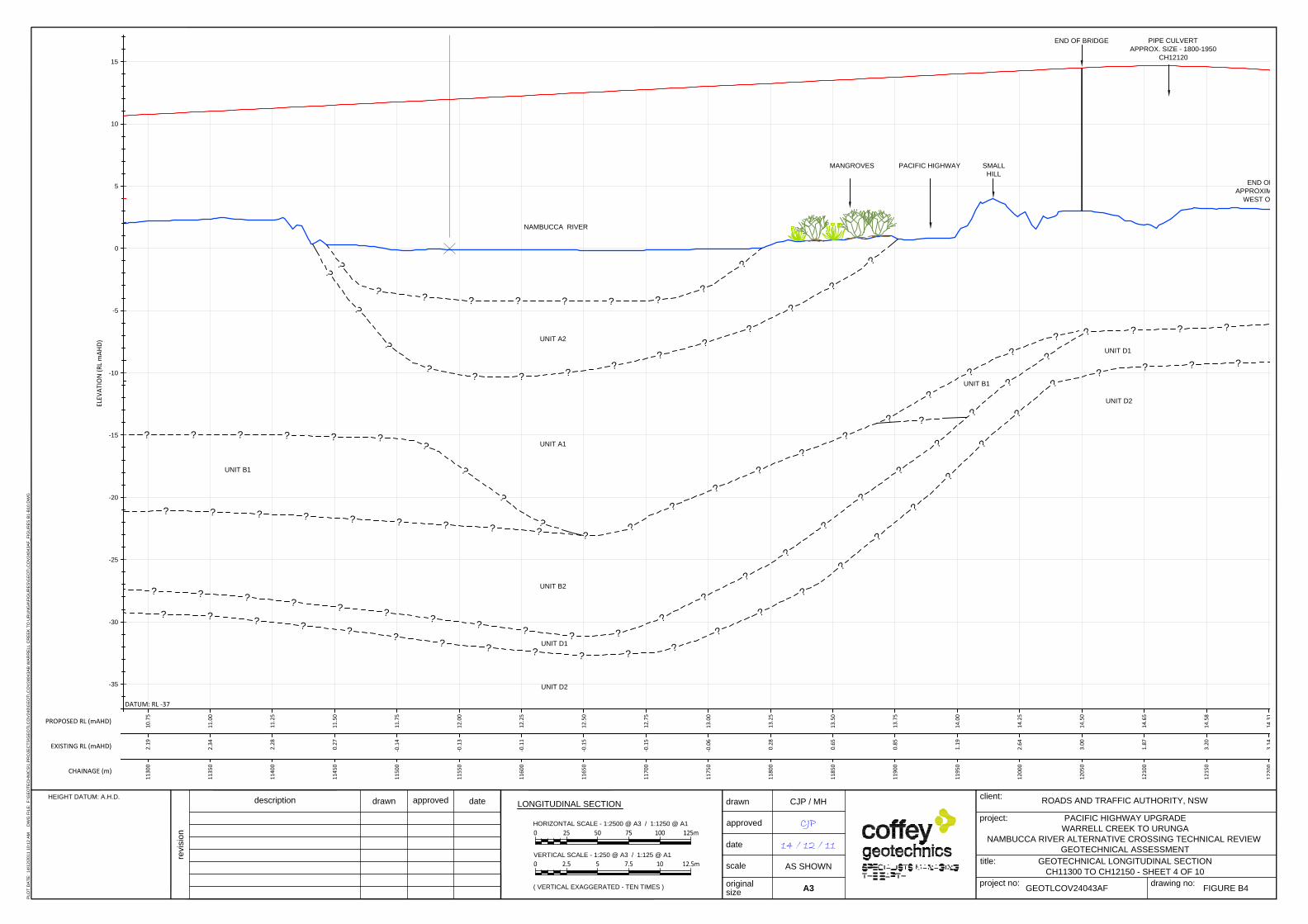
?
?
?
?
?
?
?
?
?
?
?
?
?
?
?
?
?
?
?
?
?
?
?
?
?
?
?
?
?
?
? ? ? ?
?
?
?
?
?
?
?
? ?
?
?
?
?
?
?
?
?
?
?
?
?
?
?
?
?
?
?
?
?
?
?
?
?
?
?
?
?
?
? ? ??
?
?
?
?
?
?
UNIT A2
UNIT A1
UNIT B1
UNIT B2
UNIT D1
UNIT D2
NAMBUCCA RIVER
PACIFIC HIGHWAY
?
UNIT B1
PIPE CULVERT
APPROX. SIZE - 1800-1950
CH12120
?
?
?
?
?
?
?
?
?
?
?
?
?
?
?
?
?
?
?
?
?
?
?
?
?
?
END OF RIDGELINE
APPROXIMATELY 100m TO
WEST OF ALIGNMENT
SMALL
HILL
MANGROVES
UNIT D1
UNIT D2
END OF BRIDGE
10.7
5
11.0
0
11.2
5
11.5
0
11.7
5
12.0
0
12.2
5
12.5
0
12.7
5
13.0
0
13.2
5
13.5
0
13.7
5
14.0
0
14.2
5
14.5
0
14.6
5
14.5
8
14.3
1
2.19
2.34
2.28
0.27
-0.1
4
-0.1
3
-0.1
1
-0.1
5
-0.1
5
-0.0
6
0.28
0.65
0.85
1.19
2.64
3.00
1.87
3.20
3.14
1130
0
1135
0
1140
0
1145
0
1150
0
1155
0
1160
0
1165
0
1170
0
1175
0
1180
0
1185
0
1190
0
1195
0
1200
0
1205
0
1210
0
1215
0
1220
0
-35
-30
-25
-20
-15
-10
-5
0
5
10
15
description
drawn
approved
date
project no:
drawn
approved
date
scale
project:
title:
client:
original
size
PACIFIC HIGHWAY UPGRADE
WARRELL CREEK TO URUNGA
NAMBUCCA RIVER ALTERNATIVE CROSSING TECHNICAL REVIEW
GEOTECHNICAL ASSESSMENT
A3
drawing no:
ROADS AND TRAFFIC AUTHORITY, NSW
GEOTLCOV24043AF
CJP / MH
CJP
14 / 12 / 11
revision
LONGITUDINAL SECTION
HORIZONTAL SCALE - 1:2500 @ A3 / 1:1250 @ A1
VERTICAL SCALE - 1:250 @ A3 / 1:125 @ A1
HEIGHT DATUM: A.H.D.
PROPOSED RL (mAHD)
EXISTING RL (mAHD)
CHAINAGE (m)
ELEV
ATIO
N (R
L m
AHD)
DATUM: RL
( VERTICAL EXAGGERATED - TEN TIMES )
PL
OT
D
AT
E: 1
4/1
2/2
01
1 1
0:1
2 A
M D
WG
F
IL
E: F
:\G
EO
TE
CH
NIC
S\1
.P
RO
JE
CT
S\G
EO
TL
CO
V2
40
\G
EO
TL
CO
V2
40
43
AB
W
AR
RE
LL
C
RE
EK
T
O U
RU
NG
A\F
IG
UR
ES
\G
EO
TL
CO
V2
40
43
AF
_F
IG
UR
ES
B
1-B
10
.D
WG
GEOTECHNICAL LONGITUDINAL SECTION
CH11300 TO CH12150 - SHEET 4 OF 10
AS SHOWN
FIGURE B4
-37
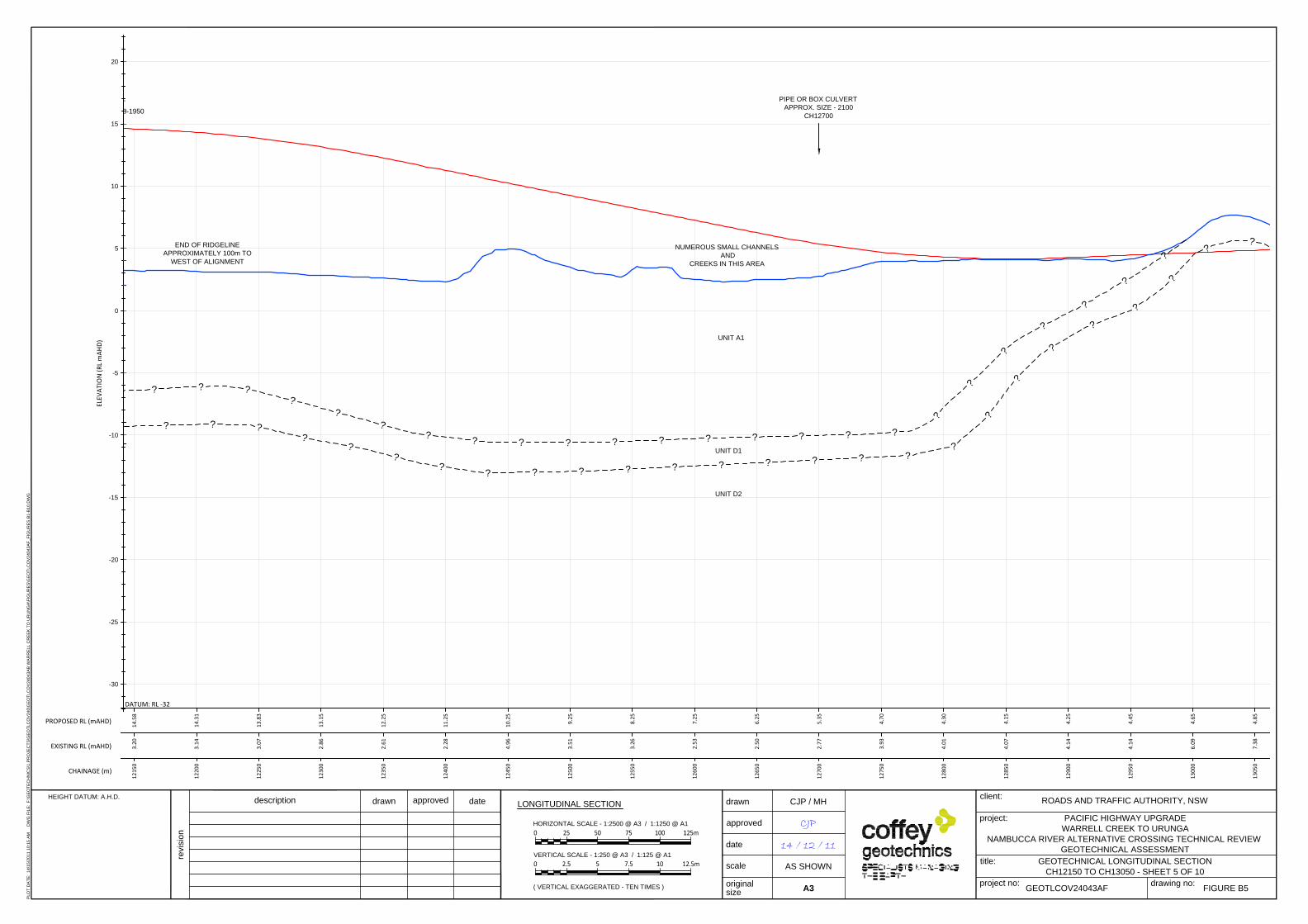
?
?
?
?
?
?
?
?
? ??
?
?
?
?
?
?
?
?
?
?
?
?
?
NUMEROUS SMALL CHANNELS
AND
CREEKS IN THIS AREA
UNIT A1
UNIT D1
UNIT D2
PIPE CULVERT
APPROX. SIZE - 1800-1950
PIPE OR BOX CULVERT
APPROX. SIZE - 2100
CH12700
?
?
?
?
?
?
?
??
?
?
?
?
?
?
?
?
?
?
?
?
?
?
?
?
?
END OF RIDGELINE
APPROXIMATELY 100m TO
WEST OF ALIGNMENT
14.5
8
14.3
1
13.8
3
13.1
5
12.2
5
11.2
5
10.2
5
9.25
8.25
7.25
6.25
5.35
4.70
4.30
4.15
4.25
4.45
4.65
4.85
3.20
3.14
3.07
2.86
2.61
2.28
4.96
3.51
3.26
2.53
2.50
2.77
3.93
4.01
4.07
4.14
4.14
6.09
7.38
1215
0
1220
0
1225
0
1230
0
1235
0
1240
0
1245
0
1250
0
1255
0
1260
0
1265
0
1270
0
1275
0
1280
0
1285
0
1290
0
1295
0
1300
0
1305
0
-30
-25
-20
-15
-10
-5
0
5
10
15
20
description
drawn
approved
date
project no:
drawn
approved
date
scale
project:
title:
client:
original
size
PACIFIC HIGHWAY UPGRADE
WARRELL CREEK TO URUNGA
NAMBUCCA RIVER ALTERNATIVE CROSSING TECHNICAL REVIEW
GEOTECHNICAL ASSESSMENT
A3
drawing no:
ROADS AND TRAFFIC AUTHORITY, NSW
GEOTLCOV24043AF
CJP / MH
CJP
14 / 12 / 11
revision
LONGITUDINAL SECTION
HORIZONTAL SCALE - 1:2500 @ A3 / 1:1250 @ A1
VERTICAL SCALE - 1:250 @ A3 / 1:125 @ A1
HEIGHT DATUM: A.H.D.
PROPOSED RL (mAHD)
EXISTING RL (mAHD)
CHAINAGE (m)
ELEV
ATIO
N (R
L m
AHD)
DATUM: RL
( VERTICAL EXAGGERATED - TEN TIMES )
PL
OT
D
AT
E: 1
4/1
5/2
01
1 1
0:1
5 A
M D
WG
F
IL
E: F
:\G
EO
TE
CH
NIC
S\1
.P
RO
JE
CT
S\G
EO
TL
CO
V2
40
\G
EO
TL
CO
V2
40
43
AB
W
AR
RE
LL
C
RE
EK
T
O U
RU
NG
A\F
IG
UR
ES
\G
EO
TL
CO
V2
40
43
AF
_F
IG
UR
ES
B
1-B
10
.D
WG
GEOTECHNICAL LONGITUDINAL SECTION
CH12150 TO CH13050 - SHEET 5 OF 10
AS SHOWN
FIGURE B5
-32

?
?
?
?
?
?
?
? ? ? ??
?
?
?
UNIT A1
UNIT D1
UNIT D2
BOX CULVERT
APPROX. SIZE - 2700 x 1500
CH13200
BOX CULVERT
APPROX. SIZE - 2 x 2700 x1500
CH13620
PIPE CULVERT
APPROX. SIZE - 1500
CH13840
?
?
?
?
UNIT C
GULLY ALLUVIUM
UNIT D1
UNIT D2
?
?
?
?
?
?
?
?
?
?
? ? ? ?
?
?
?
?
?
?
?
?
?
?
?
?
SURFACE WATER
OBSERVED AT TIME OF
SITE VISIT
(8 NOVEMBER 2011)
-30
-25
-20
-15
-10
-5
0
5
10
15
20
description
drawn
approved
date
project no:
drawn
approved
date
scale
project:
title:
client:
original
size
PACIFIC HIGHWAY UPGRADE
WARRELL CREEK TO URUNGA
NAMBUCCA RIVER ALTERNATIVE CROSSING TECHNICAL REVIEW
GEOTECHNICAL ASSESSMENT
A3
drawing no:
ROADS AND TRAFFIC AUTHORITY, NSW
GEOTLCOV24043AF
CJP / MH
CJP
14 / 12 / 11
revision
LONGITUDINAL SECTION
HORIZONTAL SCALE - 1:2500 @ A3 / 1:1250 @ A1
VERTICAL SCALE - 1:250 @ A3 / 1:125 @ A1
HEIGHT DATUM: A.H.D.
PROPOSED RL (mAHD)
EXISTING RL (mAHD)
CHAINAGE (m)
ELEV
ATIO
N (R
L m
AHD)
DATUM: RL
( VERTICAL EXAGGERATED - TEN TIMES )
PL
OT
D
AT
E: 1
4/1
6/2
01
1 1
0:1
6 A
M D
WG
F
IL
E: F
:\G
EO
TE
CH
NIC
S\1
.P
RO
JE
CT
S\G
EO
TL
CO
V2
40
\G
EO
TL
CO
V2
40
43
AB
W
AR
RE
LL
C
RE
EK
T
O U
RU
NG
A\F
IG
UR
ES
\G
EO
TL
CO
V2
40
43
AF
_F
IG
UR
ES
B
1-B
10
.D
WG
GEOTECHNICAL LONGITUDINAL SECTION
CH13050 TO CH13900 - SHEET 6 OF 10
AS SHOWN
FIGURE B6
-32
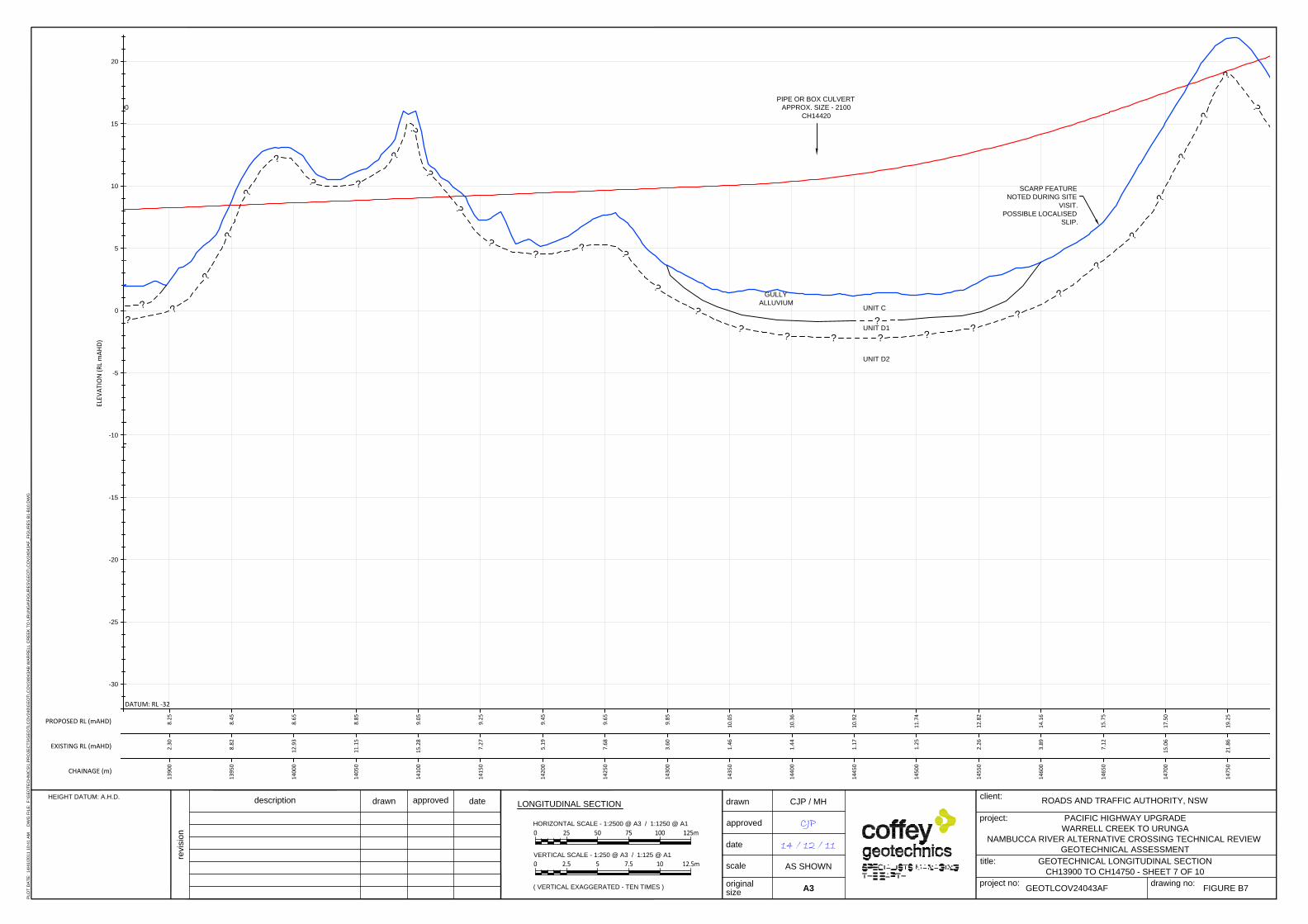
APPROX. SIZE - 1500
PIPE OR BOX CULVERT
APPROX. SIZE - 2100
CH14420
?
UNIT D1
UNIT D2
?
UNIT C
GULLY
ALLUVIUM
SCARP FEATURE
NOTED DURING SITE
VISIT.
POSSIBLE LOCALISED
SLIP.
?
?
?
?
?
?
?
?
?
?
?
?
?
?
?
?
?
?
?
?
? ?
?
?
?
?
?
?
?
?
?
?
?
8.25
8.45
8.65
8.85
9.05
9.25
9.45
9.65
9.85
10.0
5
10.3
6
10.9
2
11.7
4
12.8
2
14.1
6
15.7
5
17.5
0
19.2
5
2.30
8.82
12.9
3
11.1
5
15.2
8
7.27
5.19
7.68
3.60
1.46
1.44
1.17
1.25
2.26
3.89
7.12
15.0
6
21.8
6
1390
0
1395
0
1400
0
1405
0
1410
0
1415
0
1420
0
1425
0
1430
0
1435
0
1440
0
1445
0
1450
0
1455
0
1460
0
1465
0
1470
0
1475
0
-30
-25
-20
-15
-10
-5
0
5
10
15
20
description
drawn
approved
date
project no:
drawn
approved
date
scale
project:
title:
client:
original
size
PACIFIC HIGHWAY UPGRADE
WARRELL CREEK TO URUNGA
NAMBUCCA RIVER ALTERNATIVE CROSSING TECHNICAL REVIEW
GEOTECHNICAL ASSESSMENT
A3
drawing no:
ROADS AND TRAFFIC AUTHORITY, NSW
GEOTLCOV24043AF
CJP / MH
CJP
14 / 12 / 11
revision
LONGITUDINAL SECTION
HORIZONTAL SCALE - 1:2500 @ A3 / 1:1250 @ A1
VERTICAL SCALE - 1:250 @ A3 / 1:125 @ A1
HEIGHT DATUM: A.H.D.
PROPOSED RL (mAHD)
EXISTING RL (mAHD)
CHAINAGE (m)
ELEV
ATIO
N (R
L m
AHD)
DATUM: RL
( VERTICAL EXAGGERATED - TEN TIMES )
PL
OT
D
AT
E: 1
4/4
1/2
01
1 1
0:4
1 A
M D
WG
F
IL
E: F
:\G
EO
TE
CH
NIC
S\1
.P
RO
JE
CT
S\G
EO
TL
CO
V2
40
\G
EO
TL
CO
V2
40
43
AB
W
AR
RE
LL
C
RE
EK
T
O U
RU
NG
A\F
IG
UR
ES
\G
EO
TL
CO
V2
40
43
AF
_F
IG
UR
ES
B
1-B
10
.D
WG
GEOTECHNICAL LONGITUDINAL SECTION
CH13900 TO CH14750 - SHEET 7 OF 10
AS SHOWN
FIGURE B7
-32
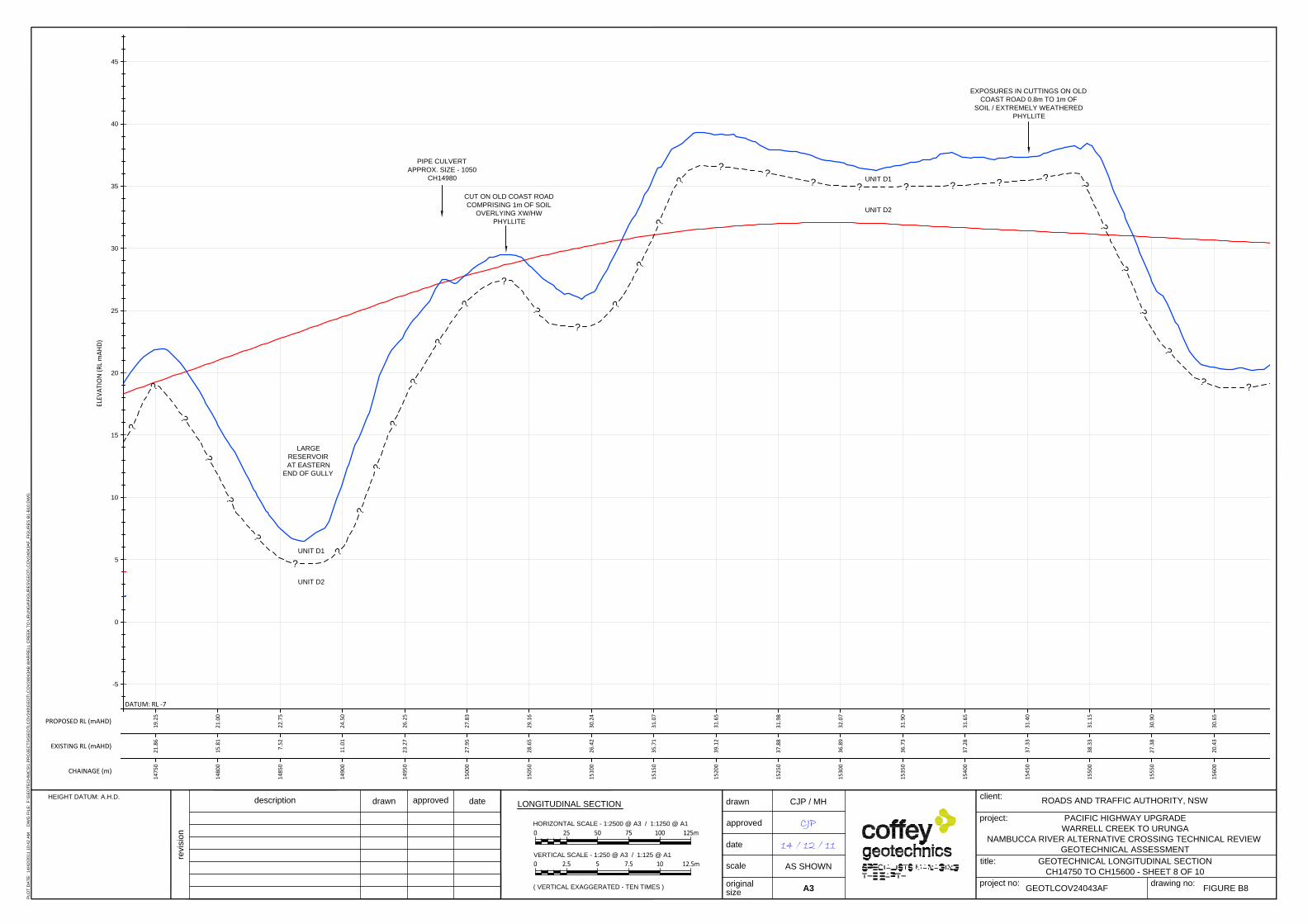
LARGE
RESERVOIR
AT EASTERN
END OF GULLY
UNIT D1
UNIT D2
UNIT D1
UNIT D2
CUT ON OLD COAST ROAD
COMPRISING 1m OF SOIL
OVERLYING XW/HW
PHYLLITE
PIPE CULVERT
APPROX. SIZE - 1050
CH14980
?
?
?
?
?
?
?
?
?
?
?
?
?
?
?
?
?
?
?
?
?
?
?
?
? ?
?
?
?
?
?
?
?
?
?
?
EXPOSURES IN CUTTINGS ON OLD
COAST ROAD 0.8m TO 1m OF
SOIL / EXTREMELY WEATHERED
PHYLLITE
19.2
5
21.0
0
22.7
5
24.5
0
26.2
5
27.8
3
29.1
6
30.2
4
31.0
7
31.6
5
31.9
8
32.0
7
31.9
0
31.6
5
31.4
0
31.1
5
30.9
0
30.6
5
21.8
6
15.8
1
7.52
11.0
1
23.2
7
27.9
5
28.6
5
26.4
2
35.7
1
39.1
2
37.8
8
36.8
9
36.7
3
37.2
8
37.3
3
38.3
3
27.3
8
20.4
3
1475
0
1480
0
1485
0
1490
0
1495
0
1500
0
1505
0
1510
0
1515
0
1520
0
1525
0
1530
0
1535
0
1540
0
1545
0
1550
0
1555
0
1560
0
-5
0
5
10
15
20
25
30
35
40
45
description
drawn
approved
date
project no:
drawn
approved
date
scale
project:
title:
client:
original
size
PACIFIC HIGHWAY UPGRADE
WARRELL CREEK TO URUNGA
NAMBUCCA RIVER ALTERNATIVE CROSSING TECHNICAL REVIEW
GEOTECHNICAL ASSESSMENT
A3
drawing no:
ROADS AND TRAFFIC AUTHORITY, NSW
GEOTLCOV24043AF
CJP / MH
CJP
14 / 12 / 11
revision
LONGITUDINAL SECTION
HORIZONTAL SCALE - 1:2500 @ A3 / 1:1250 @ A1
VERTICAL SCALE - 1:250 @ A3 / 1:125 @ A1
HEIGHT DATUM: A.H.D.
PROPOSED RL (mAHD)
EXISTING RL (mAHD)
CHAINAGE (m)
ELEV
ATIO
N (R
L m
AHD)
DATUM: RL
( VERTICAL EXAGGERATED - TEN TIMES )
PL
OT
D
AT
E: 1
4/4
2/2
01
1 1
0:4
2 A
M D
WG
F
IL
E: F
:\G
EO
TE
CH
NIC
S\1
.P
RO
JE
CT
S\G
EO
TL
CO
V2
40
\G
EO
TL
CO
V2
40
43
AB
W
AR
RE
LL
C
RE
EK
T
O U
RU
NG
A\F
IG
UR
ES
\G
EO
TL
CO
V2
40
43
AF
_F
IG
UR
ES
B
1-B
10
.D
WG
GEOTECHNICAL LONGITUDINAL SECTION
CH14750 TO CH15600 - SHEET 8 OF 10
AS SHOWN
FIGURE B8
-7

EW
HWHWEWEWHW
EWHWHWHWHW
MW
VLLM
VLEL
LL
VLMtoH
VL
M
M
M
N=R
RL 35.39mAHDOffset -33.32m
2bBH01
15
EWtoHWHWEWHWHW
HW
HW
MW
SW
MW
VLL
VLLL
L
L
M
N=13
N=23
RL 38.69mAHDOffset -59.36m
2bBH02
15
EW
HWEW
HW
HW
MW
EL
VLVLELVL
L
MLtoM
LtoM
MMtoH
N=38
N=R
RL 36.02mAHDOffset -35.36m
2bBH03
13
EW
HW
EW-HW
HWHW-SW
EL
VL/L
L
VLL
VL/L
M
N=13
N=47
N=R
RL 34.82mAHDOffset -11.97m
2bBH04
13
RL 31.07mAHDOffset -49.09m
2bEP001
5
CBR=6
CBR=12
RL 32.56mAHDOffset -25.10m
2bEP002
5
RL 39.39mAHDOffset -69.57m
2bEP003
5
HW
VL
L
CBR=6
CBR=4
RL 34.64mAHDOffset 19.39m
2bEP004
5.2
CBR=5
CBR=6
RL 33.24mAHDOffset -11.99m
2bEP005
5.2
MW
L
L-M
N=22
N=R
RL 38.17mAHDOffset -3.63m
BH2108
15.7
CBR=2
RL 36.17mAHDOffset -58.38m
TP2313
2.9
?
?
?
?
?
?
?
?
?
?
?
?
?
?
?
?
?
?
?
?
?
?
?
?
?
?
?
?
?
?
?
UNIT D1
UNIT D2
UNIT D1
UNIT D2
30.6
5
30.4
0
30.1
5
29.9
0
29.6
5
29.4
0
29.1
5
28.9
0
28.6
5
28.4
0
28.1
5
27.8
7
27.5
3
27.1
2
26.6
6
26.1
3
25.5
4
24.9
2
24.3
0
20.4
3
20.7
7
22.2
6
30.9
1
28.9
9
30.9
4
32.2
3
34.4
4
37.0
1
35.7
7
28.5
6
29.3
5
28.0
6
32.7
9
33.1
5
35.8
2
31.3
4
31.7
1
32.5
2
1560
0
1565
0
1570
0
1575
0
1580
0
1585
0
1590
0
1595
0
1600
0
1605
0
1610
0
1615
0
1620
0
1625
0
1630
0
1635
0
1640
0
1645
0
1650
0
-5
0
5
10
15
20
25
30
35
40
45
description
drawn
approved
date
project no:
drawn
approved
date
scale
project:
title:
client:
original
size
PACIFIC HIGHWAY UPGRADE
WARRELL CREEK TO URUNGA
NAMBUCCA RIVER ALTERNATIVE CROSSING TECHNICAL REVIEW
GEOTECHNICAL ASSESSMENT
A3
drawing no:
ROADS AND TRAFFIC AUTHORITY, NSW
GEOTLCOV24043AF
CJP / MH
CJP
14 / 12 / 11
revision
LONGITUDINAL SECTION
HORIZONTAL SCALE - 1:2500 @ A3 / 1:1250 @ A1
VERTICAL SCALE - 1:250 @ A3 / 1:125 @ A1
HEIGHT DATUM: A.H.D.
PROPOSED RL (mAHD)
EXISTING RL (mAHD)
CHAINAGE (m)
ELEV
ATIO
N (R
L m
AHD)
DATUM: RL
( VERTICAL EXAGGERATED - TEN TIMES )
PL
OT
D
AT
E: 1
4/4
7/2
01
1 1
0:4
7 A
M D
WG
F
IL
E: F
:\G
EO
TE
CH
NIC
S\1
.P
RO
JE
CT
S\G
EO
TL
CO
V2
40
\G
EO
TL
CO
V2
40
43
AB
W
AR
RE
LL
C
RE
EK
T
O U
RU
NG
A\F
IG
UR
ES
\G
EO
TL
CO
V2
40
43
AF
_F
IG
UR
ES
B
1-B
10
.D
WG
GEOTECHNICAL LONGITUDINAL SECTION
CH15600 TO CH16500 - SHEET 9 OF 10
AS SHOWN
FIGURE B9
-7

EW
HW
EW-HW
HWHW-SW
EL
VL/L
L
VLL
VL/L
M
N=13
N=47
N=R
RL 34.82mAHDOffset -11.97m
2bBH04
13
EW-HW
HW
HW
VL
L
VL-L
N=21
N=R
N=R
RL 28.96mAHDOffset 15.10m
2bBH05
12
EW
EW-HW
HW
VL
VL-L
L
L
L-ML
N=17
N=R
RL 31.27mAHDOffset -13.96m
2bBH06
12
CBR=5
CBR=6
RL 33.24mAHDOffset -11.99m
2bEP005
5.2
CBR=4.5
CBR=4.5
RL 32.31mAHDOffset 2.44m
2bEP006
5.2
HWVL-L
CBR=7
RL 21.40mAHDOffset 10.29m
2bTP08
3
CBR=6
RL 9.71mAHDOffset 58.41m
2bTP09
3
CBR=5
CBR=1.5
RL 13.49mAHDOffset -11.99m
2bTP10
3
CBR=3.5
RL 24.73mAHDOffset 6.12m
2bTP11
3
RL 38.99mAHDOffset -198.63m
TP2314
2.2
RL 18.31mAHDOffset 57.69m
TP2315
2.8
CBR=2CBR=1.5
RL 30.01mAHDOffset 45.12m
TP2316
2
PIPE CULVERT
APPROX. SIZE - 1500
CH16690
?
?
?
?
??
?
?
?
?
?
?
?
?
?
?
?
?
?
?
?
?
?
UNIT D1
UNIT D2
24.9
2
24.3
0
23.6
8
23.1
4
22.8
0
22.5
7
22.3
5
22.1
2
21.9
0
21.6
7
31.7
1
32.5
2
25.3
2
22.1
8
14.8
2
11.0
0
17.0
9
22.0
5
31.7
7
29.8
5
1645
0
1650
0
1655
0
1660
0
1665
0
1670
0
1675
0
1680
0
1685
0
1690
0
1693
4
-5
0
5
10
15
20
25
30
35
40
45
description
drawn
approved
date
project no:
drawn
approved
date
scale
project:
title:
client:
original
size
PACIFIC HIGHWAY UPGRADE
WARRELL CREEK TO URUNGA
NAMBUCCA RIVER ALTERNATIVE CROSSING TECHNICAL REVIEW
GEOTECHNICAL ASSESSMENT
A3
drawing no:
ROADS AND TRAFFIC AUTHORITY, NSW
GEOTLCOV24043AF
CJP / MH
CJP
14 / 12 / 11
revision
LONGITUDINAL SECTION
HORIZONTAL SCALE - 1:2500 @ A3 / 1:1250 @ A1
VERTICAL SCALE - 1:250 @ A3 / 1:125 @ A1
HEIGHT DATUM: A.H.D.
PROPOSED RL (mAHD)
EXISTING RL (mAHD)
CHAINAGE (m)
ELEV
ATIO
N (R
L m
AHD)
DATUM: RL
( VERTICAL EXAGGERATED - TEN TIMES )
PL
OT
D
AT
E: 1
4/4
8/2
01
1 1
0:4
8 A
M D
WG
F
IL
E: F
:\G
EO
TE
CH
NIC
S\1
.P
RO
JE
CT
S\G
EO
TL
CO
V2
40
\G
EO
TL
CO
V2
40
43
AB
W
AR
RE
LL
C
RE
EK
T
O U
RU
NG
A\F
IG
UR
ES
\G
EO
TL
CO
V2
40
43
AF
_F
IG
UR
ES
B
1-B
10
.D
WG
GEOTECHNICAL LONGITUDINAL SECTION
CH16450 TO CH16934 - SHEET 10 OF 10
AS SHOWN
FIGURE B10
-7