warning notes warning notes should be observed!
TRANSCRIPT


2/8
Building Technologies CC1N7454en HVAC Products 25.04.2005
Warning notes To avoid injury to persons, damage to property or the environment, the following warning notes should be observed! Do not open, interfere with or modify the unit! • All activities (mounting, installation and service work, etc.) must be performed by
qualified staff • For safety reasons – self-test of the flame supervision circuit, etc. – at least
one controlled shutdown must take place every 24 hours • Before performing any wiring changes in the connection area of the LFL1.148, com-
pletely isolate the unit from the mains supply (all-polar disconnection) • Ensure protection against electric shock hazard by providing adequate protection for
the burner control’s connection terminals • Check to ensure that wiring is in an orderly state • Press the lockout reset button only manually (do not apply a force of more than 10 N)
without using any tools or pointed objects • Do not press the lockout reset button on the unit or the remote lockout reset
button for more than 10 seconds since this would damage the lockout relay in-side the unit
• Fall or shock can adversely affect the safety functions. Such units must not be put into operation, even if they do not exhibit any damage
Mounting notes • Ensure that the relevant national safety regulations are complied with • Connect the earthing lug inside the terminal base to burner ground using a screw
with a lockwasher or similar
Installation notes • Always run the high-voltage ignition cables separately while observing the greatest
possible distance to the unit and to other cables • Do not mix up live and neutral conductors
Electrical connection of the ionization probe It is important to achieve practically disturbance- and loss-free signal transmission: • Never run the ionization cable together with other cables
– Line capacitance reduces the magnitude of the flame signal – Use a separate cable of low capacitance
• The ionization probe is not protected against electric shock hazard • Locate the ignition electrode and the ionization probe such that the ignition spark
cannot arc over to the ionization probe (risk of electrical overloads)

3/8
Building Technologies CC1N7454en HVAC Products 25.04.2005
Commissioning notes • Prior to commissioning, check to ensure that wiring is in an orderly state • When commissioning the plant or when doing maintenance work, make the following
safety checks:
Safety check to be carried out Anticipated response a) Burner startup with ionization cable
disconnected Lockout at the end of «TSA»
Standards and certificates
Conformity to EEC directives - Electromagnetic compatibility EMC (immunity) - Directive for gas appliances
89 / 336 EEC 90 / 396 EEC
ISO 9001: 2000 Cert. 00739
ISO 14001: 1996 Cert. 38233
• Identification code to EN 298 A T L L X N
Certified complete with plug-in base:
Service notes • Each time a unit has been replaced, check to ensure that wiring is in an orderly state.
Make the safety check in accordance with the «Commissioning notes»
Disposal notes The unit contains electrical and electronic components and must not be disposed of to-gether with domestic waste. Local and currently valid legislation must be observed.
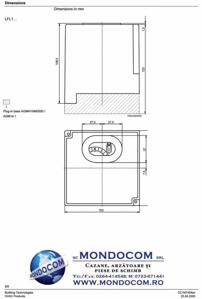
Mechanical design The mechanical design of the LFL1.148 corresponds to that of the standard units of the LFL... range (refer to Data Sheet N7451).
Ordering Gas burner control, without plug-in base LFL1.148 Plug-in base not included in the delivery, must be ordered as a separate item! Connection accessories for medium-capacity refer to Data Sheet N7230 burner controls - Plug-in base AGM410490550 with Pg11 threads for cable entry glands - Plug-in base AGM14.1 with M16 threads for cable entry glands Ionization probe to be supplied by thirds Test unit KF8806 for burner control refer to Operating Instructions B7987 - For the simulation of faults - For checking the flame relay’s pull-in and drop-out values in the case of flame supervi-
sion by ionization probe

4/8
Building Technologies CC1N7454en HVAC Products 25.04.2005
Technical data For technical data – with the exception of the data listed below and the switching times of the switching mechanism – refer to Data Sheet N7451. Perm. length of detector cable - Normal cable, laid separately - Shielded cable, shielding connected to
terminal 22, e.g. high-frequency cable
max. 50 m max. 100 m
Capacity - Output on startup (without fan
assistance) - Nominal output
any (with ignition < 120 kW) any
Storage DIN EN 60721-3-1 Climatic conditions class 1K3 Mechanical conditions class 1M2 Temperature range -20...+60 °C Humidity < 95 % r.h.
Transport DIN EN 60 721-3-2 Climatic conditions class 2K2 Mechanical conditions class 2M2 Temperature range -40...+60 °C Humidity < 95 % r.h. Operation DIN EN 60 721-3-3 Climatic conditions class 3K5 Mechanical conditions class 3M2 Temperature range -20...+60 °C Humidity < 95 % r.h. Condensation, formation of ice and ingress of water are not permitted!
Function In terms of control program and flame supervision (including test of the flame supervision circuit), the functions of the LFL1.148 correspond of those of the standard units of the LFL.... range. There is a difference however in the control of actuator «SA» and of load controller «LR», especially with regard to the air damper position on startup and closing of the air damper during controlled shutdown. Supervision of the respective start position is accomplished via an auxiliary switch in the damper actuator whose contact must be included in the start control loop between termi-nals 4 and 5. It must be ensured that the current path between terminals 4 and 5 remains closed until controlled shutdown takes place. During controlled shutdown, the air damper is driven to the fully closed position via con-tact «Vlb» of the switching mechanism. Since the switching mechanism of the burner control does not continue to run until changeover of limit switch «z» in the air damper actuator occurs, the running time of actuator «SA» is optional. The pilot flame is supervised by ionization probe «ION1», the main flame by ionization probe «ION2». On completion of the ignition safety time «TSA», a flame signal must be present at terminal 23 «ION1». On completion of the second safety time «t9», a flame signal must also be present at terminal 24 «ION2».
General unit data
Environmental conditions

5/8
Building Technologies CC1N7454en HVAC Products 25.04.2005
Control program In the event of fault and lockout indication:
◄ No start For example: Start control loop interrupted via «SA»
Lockout due to a fault in the flame supervision circuit
▼ Abortion of startup sequence because the auxiliary switch in actuator «SA» has cut the start control loop
1 Lockout, because no flame signal was present on completion of the ignition safety time «TSA»
2 Lockout because no flame signal was present on completion of the second safety time
▌ Lockout because the flame signal was lost during burner operation
◄ Lockout on completion of the control program, due to extraneous light or a faulty flame signal For example: Flame not extinguished
After the reset, the burner control’s switching mechanism first returns to the start position and then initiates a burner restart.
Connection diagram
1 2 3 21 4 12 5 14 6 8(7)
16 18 19 11 15 22 23 24
H
LN
AL
EK2 W
R
GP M1 Z BV1 BV2ION1
ION2
7454a04/0204
LFL1.148
SB
Si
Connection examples 5 4 12 15 20 11 6 8
W
R
LP
7454a02/1195
2-stage forced draft gas burner without load controller «LR» and without actuator «SA»
W
R
5 4 12 8 6 14 15 20 11
7454a03/1195
Atmospheric gas burner without fan assis-tance, load controller «LR» and actuator «SA»

6/8
Building Technologies CC1N7454en HVAC Products 25.04.2005
Basic diagram
L H
1
AS
br1
ar1 I XV ar2
ION2
22 23 2476124
W
x
yR
LP
d1d2
5 13 14
N
M1 M2
d1 d2
22 23 24
ION1
X
fr1
XI XIIIXII
AR
br2L1
EK1
BR
3 21 2 16
AL
NH
EK2
1
9 10 18 19
Z BV1 BV2
1 L
N
Y1
15 20 11 86B1
M
Q
LK
x y
SAa z mM
Y2
LR
E
A
M
ab b
a
a b b a
a b
ba a b
fr3
NTC
fr2 FRV
(1) (1)
a b
XIV IV
VIIa bar3
V
IX
VIa b
M~SMVIIIIIIII
b ba
a
7454a01/0204
SB
ϑ
Si
Do not press EK... for more than 10 seconds!
Control program
SB/R/W
M1
Z
BV1
BV2
FS1
FS2
A B C D
t1 t6
t7 t3 t20
TSA t9
t4 t5
t8 7454d02/0204
1
6
7
16
18
19
23
24

7/8
Building Technologies CC1N7454en HVAC Products 25.04.2005
Diagram of switching mechanism
t1 t3 t6
t7 t4 t5
t8
t10
TSA
t9
t20
A B C D
abab
ababab
ab
XV
XIV
XIII
XII
XI
XIX
VIII
VII
VI
VIVIII
II
I
7454d01/0204
ab
1916
9 10
2011
818
1523 24
127
712
ababab
a
a
a
a
b
Legend
AL Remote lockout indication → Alarm Output signals of burner control AS Unit fuse Required input signals AR Main relay with contacts «ar...» → Working relay BR Lockout relay with contacts «br...» A Start command given by the control thermostat BV... Fuel valve A-B Startup sequence d1/d2 Contactor or relay B Operating position of burner EK... Reset button B-C Burner operation ION... Ionization probe C Controlled shutdown by «R» FR Flame relay with contacts «fr...» C-D Sequence mechanism runs to the end position after a GP Gas pressure switch controlled shutdown by «R» H Main isolator D End position of burner → Corresponding to the start position L1 Lockout warning lamp LK Air damper Switching times in seconds LP Air pressure switch LR Load controller TSA Ignition safety time 4 sM1/M2 Fan or burner motor t1 Waiting time or prepurge time 14 sNTC NTC resistor t3 Preignition time 2 sR Control thermostat or pressurestat t4 Interval «BV1-BV2» 8 sSA Air damper actuator t5 Interval between release of the 2nd fuel valve and the load
a: Changeover limit switch for actuator’s OPEN position controller (if present) 10 sz: Changeover limit switch for actuator’s CLOSED position t6 Postpurge time 10 s
SB Safety limit thermostat t7 Interval until voltage at terminal 7 is present 2 sSi External primary fuse t8 Duration of startup program 36 sSM Synchronous motor of sequence mechanism t9 2nd safety time for 2nd stage 8 sV Flame signal amplifier t10 Interval until air pressure check is started 6 s(1) Input for forced energizing of the flame relay during the t20 Steps of switching mechanism with no change in the 26 s functional test of the flame supervision circuit program → Idle steps (contact «XIV») and during «TSA» (contact «IV») W Limit thermostat or pressure switch Z Ignition transformer