want to take a run (or walk)? - the national board of ... · want to take a run (or walk)? ... 2013...
TRANSCRIPT

WANT TO TAKE A RUN (or WALK)?
NATIONAL BOARD & ASME
STEAMCHASERSRUN
WALK85th General Meeting Orlando, FloridaAll attendees and guests of the General Meeting and ASME Code Week are invited to participate in a free 5K charity event on Sunday, May, 8, at 8:00 a.m. Event will start and finish at the Gaylord Palms Convention Center Entrance. The General Meeting will make a donation to “Team Red, White, and Blue” to support American veterans.
Learn more and register online now at nationalboard.org under the General Meeting tab and then click Infolink! 2016.
FEATURESNational Board SynopsisUpdate
Steam Plant Operations Correct Venting from a Boiler Feedwater Deaerator
The Installation and Inspection of Probe-Type (Conductance-Actuated) Controls for Proper and Safe Operation Part One in a Two-Part Series
The 2015 National Board Incident Report Based on 2010 OSHA Data
Red Zone – Places of High Hazard
The 85th General Meeting Orlando, Florida, 2016
Water Level Indicators
Arizona Statistics Show Notable Growth
3
6
4
10
12
44
22
16
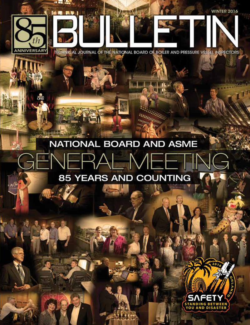
On the Cover:Eighty-five years of General Meetings.
Executive Director’s Message
Pressure Relief Report
Inspector’s Insight
Profile in Safety
Training Matters
Training Courses and Seminars
Updates & Transitions
DEPARTMENTS
COVER STORY
2
3840
41
36
26
20
42
CONTENTS WINTER 2016VOLUME 71 NUMBER 1
Please RecycleThis MagazineRemove Cover And Inserts Before Recycling
nationalboard.org
David A. DouinExecutive Director
Richard L. AllisonAssistant Executive Director – Administrative
Charles WithersAssistant Executive Director – Technical
Paul D. Brennan, APR Director of Public Affairs
Wendy WhitePublications Editor
Brandon SofskyManager of Publications
BOARD OF TRUSTEESJohn Burpee
ChairmanJoel T. AmatoFirst Vice ChairmanMichael Burns
Second Vice ChairmanDavid A. DouinSecretary-Treasurer
Christopher B. CantrellMember at Large
Milton WashingtonMember at Large
ADVISORY COMMITTEEBarry Berquist
Representing pressure vessel manufacturersPhillip F. Martin
Representing organized laborPeter A. Molvie
Representing boiler manufacturersKathy Moore
Representing National Board stamp holdersJames Pillow
Representing the welding industryH. Michael Richards
Representing boiler and pressure vessel usersRobert V. Wielgoszinski
Representing authorized inspection agencies(insurance companies)
The National Board of Boiler and Pressure Vessel Inspectors was organized for the purpose of promoting greater safety by securing concerted action and maintaining uniformity in the construction, installation, inspection, and repair of boilers and other pressure vessels and their appurtenances, thereby ensuring acceptance and interchangeability among jurisdictional authorities empowered to ensure adherence to code construction and repair of boilers and pressure vessels.
The National Board BULLETIN is published three times a year by The National Board of Boiler and Pressure Vessel Inspectors, 1055 Crupper Avenue, Columbus, Ohio 43229-1183, 614.888.8320, nationalboard.org. Postage paid in Columbus, Ohio.
Points of view, ideas, products, or services featured in the National Board BULLETIN do not constitute endorsement by the National Board, which disclaims responsibility for authenticity or accuracy of information contained herein. Address all correspondence to the Public Affairs Department, The National Board of Boiler and Pressure Vessel Inspectors, at the above address.
© 2016 by The National Board of Boiler and Pressure Vessel Inspectors. All rights reserved. Printed in the USA. ISSN 0894-9611. CPN 4004-5415.
The National Board and ASME General Meeting: 85 Years and Counting
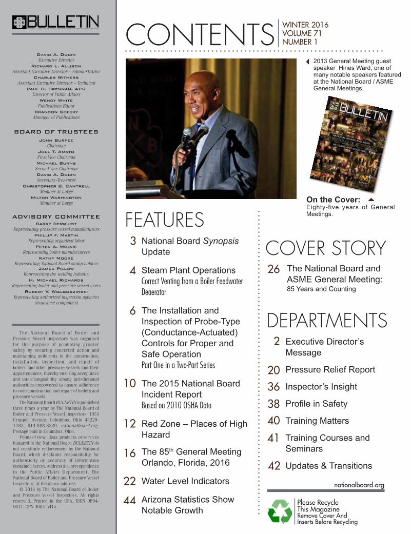
2013 General Meeting guest speaker Hines Ward, one of many notable speakers featured at the National Board / ASME General Meetings.
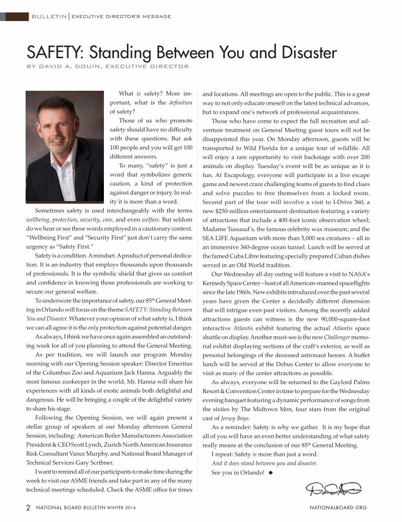
What is safety? More im-portant, what is the definition of safety?
Those of us who promote safety should have no difficulty with these questions. But ask 100 people and you will get 100 different answers.
To many, “safety” is just a word that symbolizes generic caution, a kind of protection against danger or injury. In real-ity it is more than a word.
Sometimes safety is used interchangeably with the terms wellbeing, protection, security, care, and even welfare. But seldom do we hear or see these words employed in a cautionary context. “Wellbeing First” and “Security First” just don’t carry the same urgency as “Safety First.”
Safety is a condition. A mindset. A product of personal dedica-tion. It is an industry that employs thousands upon thousands of professionals. It is the symbolic shield that gives us comfort and confidence in knowing those professionals are working to secure our general welfare.
To underscore the importance of safety, our 85th General Meet-ing in Orlando will focus on the theme SAFETY: Standing Between You and Disaster. Whatever your opinion of what safety is, I think we can all agree it is the only protection against potential danger.
As always, I think we have once again assembled an outstand-ing week for all of you planning to attend the General Meeting.
As per tradition, we will launch our program Monday morning with our Opening Session speaker: Director Emeritus of the Columbus Zoo and Aquarium Jack Hanna. Arguably the most famous zookeeper in the world, Mr. Hanna will share his experiences with all kinds of exotic animals both delightful and dangerous. He will be bringing a couple of the delightful variety to share his stage.
Following the Opening Session, we will again present a stellar group of speakers at our Monday afternoon General Session, including: American Boiler Manufacturers Association President & CEO Scott Lynch, Zurich North American Insurance Risk Consultant Vance Murphy, and National Board Manager of Technical Services Gary Scribner.
I want to remind all of our participants to make time during the week to visit our ASME friends and take part in any of the many technical meetings scheduled. Check the ASME office for times
BY DAVID A. DOUIN, EXECUTIVE DIRECTOR
SAFETY: Standing Between You and Disaster
and locations. All meetings are open to the public. This is a great way to not only educate oneself on the latest technical advances, but to expand one’s network of professional acquaintances.
Those who have come to expect the full recreation and ad-venture treatment on General Meeting guest tours will not be disappointed this year. On Monday afternoon, guests will be transported to Wild Florida for a unique tour of wildlife. All will enjoy a rare opportunity to visit backstage with over 200 animals on display. Tuesday’s event will be as unique as it is fun. At Escapology, everyone will participate in a live escape game and newest craze challenging teams of guests to find clues and solve puzzles to free themselves from a locked room. Second part of the tour will involve a visit to I-Drive 360, a new $250-million entertainment destination featuring a variety of attractions that include a 400-foot iconic observation wheel; Madame Tussaud’s, the famous celebrity wax museum; and the SEA LIFE Aquarium with more than 5,000 sea creatures – all in an immersive 360-degree ocean tunnel. Lunch will be served at the famed Cuba Libre featuring specially prepared Cuban dishes served in an Old World tradition.
Our Wednesday all day outing will feature a visit to NASA’s Kennedy Space Center – host of all American-manned spaceflights since the late 1960s. New exhibits introduced over the past several years have given the Center a decidedly different dimension that will intrigue even past visitors. Among the recently added attractions guests can witness is the new 90,000-square-foot interactive Atlantis exhibit featuring the actual Atlantis space shuttle on display. Another must-see is the new Challenger memo-rial exhibit displaying sections of the craft’s exterior, as well as personal belongings of the deceased astronaut heroes. A buffet lunch will be served at the Debus Center to allow everyone to visit as many of the center attractions as possible.
As always, everyone will be returned to the Gaylord Palms Resort & Convention Center in time to prepare for the Wednesday evening banquet featuring a dynamic performance of songs from the sixties by The Midtown Men, four stars from the original cast of Jersey Boys.
As a reminder: Safety is why we gather. It is my hope that all of you will have an even better understanding of what safety really means at the conclusion of our 85th General Meeting.
I repeat: Safety is more than just a word. And it does stand between you and disaster.See you in Orlando!
2 NATIONAL BOARD BULLETIN WINTER 2016 NATIONALBOARD.ORG
BULLETIN EXECUTIVE DIRECTOR'S MESSAGE

BULLETIN
3WINTER 2016 NATIONAL BOARD BULLETIN NATIONALBOARD.ORG
FEATURE
JURISDICTION DEPARTMENT DATE OF LAW PASSAGE
RULES FOR CONSTRUCTION AND
STAMPING
INSPECTIONS REQUIRED
INSURANCE INSPECTION
REQUIREMENTSFEES MISC
US STATES
Alaska X
California X
Illinois X X
Iowa X X X X X
Kansas X
Kentucky X
Louisiana X
Michigan X X X
Mississippi X
Missouri X
New York X X
North Carolina X X X
North Dakota X
Ohio X
Tennessee X
Utah X
Washington X X
CANADIAN PROVINCES/TERRITORIES
Alberta X X X X
Manitoba X
US CITIES/TERRITORIES
Chicago X
Detroit X
Puerto Rico X X
The National Board Synopsis (NB-370) is a compilation of jurisdiction laws, rules, and regulations as reported to the National Board by jurisdictional authorities. The table below notes changes by category for 2015. Jurisdictions not listed either had no changes or did not submit changes at time of printing. For more information, go to
nationalboard.org under “Resources” to view the complete Synopsis. Data is subject to change; consult the appropriate jurisdiction for final verification. STATES
National Board Synopsis Update
FEATURE
4 NATIONAL BOARD BULLETIN WINTER 2016 NATIONALBOARD.ORG
BULLETIN
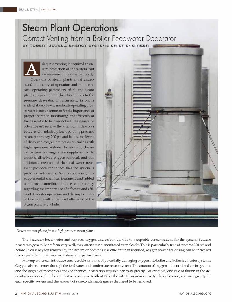
Steam Plant OperationsCorrect Venting from a Boiler Feedwater DeaeratorBY ROBERT JEWELL, ENERGY SYSTEMS CHIEF ENGINEER
dequate venting is required to en-sure protection of the system, but excessive venting can be very costly.
Operators of steam plants must under-stand the theory of operation and the neces-sary operating parameters of all the steam plant equipment, and this also applies to the pressure deaerator. Unfortunately, in plants with relatively low to moderate operating pres-sures, it is not uncommon for the importance of proper operation, monitoring, and efficiency of the deaerator to be overlooked. The deaerator often doesn’t receive the attention it deserves because with relatively low-operating pressure steam plants, say 200 psi and below, the levels of dissolved oxygen are not as crucial as with higher-pressure systems. In addition, chemi-cal oxygen scavengers are supplemented to enhance dissolved oxygen removal, and this additional measure of chemical water treat-ment provides confidence that the system is protected sufficiently. As a consequence, this supplemental chemical treatment and added confidence sometimes induce complacency regarding the importance of effective and effi-cient deaerator operation, and the implications of this can result in reduced efficiency of the steam plant as a whole.
Deaerator vent plume from a high-pressure steam plant.
The deaerator heats water and removes oxygen and carbon dioxide to acceptable concentrations for the system. Because deaerators generally perform very well, they often are not monitored very closely. This is particularly true of systems 200 psi and below. Even if oxygen removal by the deaerator becomes less efficient than required, oxygen scavenger dosing can be increased to compensate for deficiencies in deaerator performance.
Makeup water can introduce considerable amounts of potentially damaging oxygen into boiler and boiler feedwater systems. Oxygen also can enter through the feedwater and condensate return system. The amount of oxygen and entrained air in systems and the degree of mechanical and/or chemical deaeration required can vary greatly. For example, one rule of thumb in the de-aerator industry is that the vent valve passes one-tenth of 1% of the rated deaerator capacity. This, of course, can vary greatly for each specific system and the amount of non-condensable gasses that need to be removed.
Deaerator vent plume from a high-pressure steam plant.
AA
5 WINTER 2016 NATIONAL BOARD BULLETIN NATIONALBOARD.ORG
Ask yourself these questions:• What type of deaerator do I have?• At what temperature and pressure does the deaerator
operate? • What is the deaerator’s design removal efficiency for
oxygen and carbon dioxide?• What is the current oxygen concentration of the wa-
ter in the deaerator storage section with and without chemical oxygen scavenger addition?
• How much steam is the deaerator venting?If you cannot readily answer any one of these questions,
further educating yourself regarding the specifics of your par-ticular system may prove to be very beneficial.
Pressure deaerators are commonly designed and specified with removal efficiencies for dissolved oxygen down to 7 parts per billion (ppb) and carbon dioxide down to 0 ppb. When mechanical deaerators are supplemented with chemical oxygen scavengers, the dissolved oxygen can be reduced further. A rela-tively common rule of thumb is that a dissolved oxygen level of 5 ppb or less is typically strongly recommended for systems operating at 200 psi and above; while lower-pressure systems, under 200 psi, generally can tolerate levels up to about 40 ppb dissolved oxygen. Equipment life can be extended at little cost by limiting oxygen concentration in either system to ≤ 5 ppb. Residual levels of chemical oxygen scavengers should be main-tained in order to account for excursions in system operation or equipment issues that may result in unexpected elevated levels of dissolved oxygen.
The cost to generate steam dictates that the deaerator vent must be investigated to ensure excessive venting of steam is not occurring, yet still ensure adequate deaeration. Evaluation of mechanical deaerators has revealed steam losses of tens of thousands of dollars, and in some cases, losses that have exceeded $100,000 a year because of unnecessary, excessive venting from the deaerator. In individual cases, where the excessive venting was addressed, water savings of greater than 1,000,000 gallons per year have been realized.
Don’t just think about it as some wasted steam. The system as a whole needs to be considered. Once that is appreciated, it is easy to see that the benefits of minimizing excessive venting begin to multiply quickly. Any water that is wasted through excessive venting of steam must be replaced. That means: ad-ditional fuel; wasted valuable BTUs in the steam; wasted water; reduced ratio of steam condensate returned, which increases the cycles of concentration in the boiler and required surface bleed to control conductivity; increased chemical treatment requirements; increased pretreatment of water for makeup water to the system, such as water softening requirements; and so on. Excessive vent-ing also increases the amount of wastewater that must be dealt
with due to increased surface bleed for conductivity control and increased water softener regeneration frequency, and so forth.
A balance between ensuring adequate deaeration and minimizing wasteful excessive venting should be maintained. The benefits of minimizing excessive venting beyond that which is required is cumulative.
One relatively crude method of measuring adequate vent plume and deaeration consists of observing the height of the vent plume. Recommendations for plume height vary between 18 and 36 inches. The question is often asked, “How big does the deaerator plume need to be to achieve proper deaeration?” The short answer is, “Proper deaeration cannot be confirmed by the height of the plume alone,” yet frequently this is the only monitoring method utilized to gauge deaerator operation.
Methods of measurement of dissolved oxygen are often thought to be complicated, costly, and include instrumentation that can be hard for relatively small systems to justify. There are, in fact, several methods of measuring dissolved oxygen, some of which are very economical and relatively simple to use.
These include:The AmpuImetric Method test, which offers ease of opera-
tion and minimal time spent collecting reliable data. Ampules are available in the 0-100 ppb range, are relatively easy to use, inexpensive, and ideal for small to moderately sized systems.
The Indigo Carmine Method is a colorimetric procedure for determining amounts of dissolved oxygen in the 0 to 100 ppb range.
Oxygen analyzers offer accurate, reliable, direct measure-ment in liquid streams. They are used to monitor dissolved oxygen continuously or intermittently at various points in the condensate and feedwater systems and are often used for more critical, high-pressure; or larger, more complex systems.
In summary, deaerators perform a vital function in the safe, effective, and efficient production of steam and ensuring the longevity of steam plant equipment. However, knowledge of how they work and how they should be operated, maintained, and monitored is necessary if they are to perform effectively and efficiently. Inefficient deaeration can increase the cost of opera-tions, result in damage to equipment, and drastically increase water usage and wastewater discharged.
Quantifying dissolved oxygen levels and removal effi-ciencies of the deaerator while also ensuring adequate, yet not wasteful, venting is imperative to safe and effective operation, protection of assets, and managing the cost of operations.
Robert Jewell has 30 years of career experience in industrial utili-ties. He specializes in the operation, maintenance, and management of steam plants, central plants, cooling and refrigeration systems, potable (drinking) water systems, water treatment, wastewater treatment, and facility management.

FEATURE
6 NATIONAL BOARD BULLETIN WINTER 2016 NATIONALBOARD.ORG
BULLETIN
Probe-style low-water cutoffs have been used in the boiler industry for many years to provide primary and secondary low-water protection. The controls utilize the water of the boiler, which acts as a conductor and provides an indication to a relay or electronic circuitry that there is water at the probe and water interface. These relays then provide a permissive for the burner circuit to allow the safe operation of the burner. However, there is an inherent fail-unsafe mode if these controls are not properly installed, maintained, serviced, or tested. This article will explain the correct installation and testing of these controls so as to provide a safe and reliable control for boiler operation.
“”
Let’s start with a definition of a conductance-actuated level control. Conductance is the ability of a material to conduct an electric current. Some materials, such as copper, are excellent conductors
and have a high conductance; other materials, such as plastic, have a very low conductance. Boiler water does have the ability to conduct current. Due to the widely varying properties of boiler water, there are also widely varying levels of conductivity.
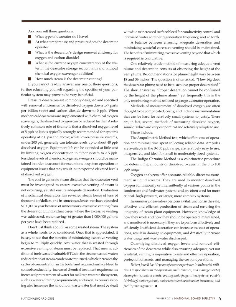
Conductance-activated level controls originally consisted of a trans-former, relay coil, and contacts mechanically connected to the coil. These were electro-mechanical devices. Figure 1 shows this configuration. When the boiler water is in contact with the steel pressure vessel and the probe, the electrical circuit is completed through the boiler water, causing the relay coil to energize and transfer the contact position. Depending on the conductivity of the boiler water, the secondary volt-age could be changed in order to have the correct amount of current to energize the relay coil.
This configuration is safe as long as there are no alternative paths for the current to flow and energize the relay. This configuration is not fail-safe, however. If there is resistance between the probe and steel vessel that is equal to or less than the resistance of the boiler water, an alternate path is provided for the coil to be energized and the relay contacts will transfer position regardless of the true water level in the boiler. These controls cannot distinguish between the probe being exposed to water and the probe wiring becoming shorted to ground.
The Installation and Inspection of P robe-Type (Conductance-Actuated) Controls for Proper and Safe Oper ation Part One in a Two-Part SeriesBY STEVE KALMBACH
So how can problems with conductance-
actuated controls be eliminated in order to
improve their reliability and safety for use in
boiler service? There are numerous techniques and tools that can be
used during installation, testing, servicing, and
inspection.
Steve Kalmbach is the owner of Kasco, a boiler repair shop in Colorado. He can be reached at [email protected]
7 WINTER 2016 NATIONAL BOARD BULLETIN NATIONALBOARD.ORG
The Installation and Inspection of P robe-Type (Conductance-Actuated) Controls for Proper and Safe Oper ation Part One in a Two-Part SeriesBY STEVE KALMBACH
It is possible for these controls to be equipped with a secondary voltage of up to 500. Current flow is a function of the voltage applied to a resistance. With the higher voltage it would be possible to obtain enough current to trigger the relay with the fairly wide range of resis-tance currently used with lower second-ary voltage in new-generation controls. Interchanging of the connection to the probe and ground will permit the same unsafe failure condition.
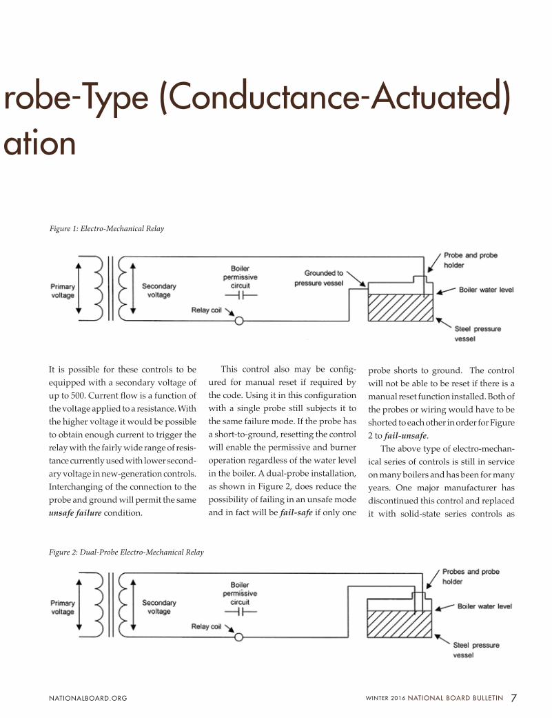
This control also may be config-ured for manual reset if required by the code. Using it in this configuration with a single probe still subjects it to the same failure mode. If the probe has a short-to-ground, resetting the control will enable the permissive and burner operation regardless of the water level in the boiler. A dual-probe installation, as shown in Figure 2, does reduce the possibility of failing in an unsafe mode and in fact will be fail-safe if only one
probe shorts to ground. The control will not be able to be reset if there is a manual reset function installed. Both of the probes or wiring would have to be shorted to each other in order for Figure 2 to fail-unsafe.
The above type of electro-mechan-ical series of controls is still in service on many boilers and has been for many years. One major manufacturer has discontinued this control and replaced it with solid-state series controls as
Figure 1: Electro-Mechanical Relay
Figure 2: Dual-Probe Electro-Mechanical Relay

FEATURE
8 NATIONAL BOARD BULLETIN WINTER 2016 NATIONALBOARD.ORG
BULLETIN
be a false positive. If the probe wiring is shorted to ground, the control will disable the burner and then reset even if there is no water on the probe. Usu-ally this feature is used when the probe is installed in the shell of the boiler and it is not possible to do an actual test by lowering the water level in the boiler. If the probe is shorted to ground, this will not give a positive indication of proper and safe operation.
Some controls may also have an automatic reset feature for when there is a power failure. If the water level was normal prior to the power failure and continues to be after power is restored, and if the water level is above the probe, the relay will be energized and the burner may be enabled. If it is also equipped with a manual reset feature and the water level is below the probe
with a shorted probe, the control may also be energized and enable the burner. Either of these configurations is not fail-safe. There is a potential problem if there is a power failure. If the power failure is for an extended amount of time and boiler water is lost through evaporation, the burner may be enabled when power is restored. This may al-low the boiler to be fired without a safe water operating level.
So how can problems with conduc-tance-actuated controls be eliminated in order to improve their reliability and safety for use in boiler service? There are numerous techniques and tools that can be used during installation, testing, servicing, and inspection. First, let’s look at some techniques that can be employed during the installation of a boiler.
shown in Figures 3 and 4. Along with this upgrade, they are able to provide functions that were not available with some of the earlier controls. These functions include manual reset, testing of control operation, and power loss function auto reset.
This latest series of electronic con-ductance-actuated controls still relies on conductance for operation and therefore are subject to some of the same problems as the earlier conductance relays. These newer controls also have additional fea-tures that were not available for the ear-lier controls. One feature that appears to improve the safety of the controls is the test feature. Using this test feature while the burner is operating would appear to show that the control is safe as the burner is disabled and then can be manually reset. However, this can
Figure 4: Solid State Relay
Figure 3: Solid State Relay (Grounded to Pressure Vessel)

9 WINTER 2016 NATIONAL BOARD BULLETIN NATIONALBOARD.ORG
Installation
Installation of equipment provides an excellent opportunity to check conduc-tance-actuated controls to ensure they are installed correctly and will function properly. Following is a list of suggested procedures and reminders to consider during installation. 1. If possible during installation, use
an external probe column equipped with dual probes. (See Figure 2.) Manufacturers sometimes will use the most cost-effective way of meeting code requirements for the second low-water cutoff by installing a coupling in the shell, which usually only incorporates a single probe. A single probe will use a 1-inch coupling, whereas a dual probe will require a 2-inch coupling in the shell. By mounting the probe externally to the boiler you are able to test the functionality without draining the boiler. Even a single probe can be tested this way; however, the single probe will not provide fail-safe operation while in service.
2. Use a wire that will be rated for the expected temperature condi-tions and route all the electrical conduit clear of hot boiler surfaces. A boiler that is operating at 125 psi will have a steam temperature of 353°F (178°C). Normal THHN wire is usually only rated for 90°C. Any contact with piping or the con-nections on the probe holder may disable the insulating properties
of this wiring. It is suggested that high-temperature wire be used, such as a silicone insulation, which is usually rated for 200°C. In some cases a Teflon-covered wire may be needed. Avoid using wiring that may absorb water, reducing its insulating properties.
3. Confirm that the wire insulation has not been damaged during installation. Since these are low-voltage circuits, a short or damaged insulation will not short out and blow a fuse or trip a circuit breaker. Confirm the insulation integrity before terminating the wire at the control by performing a resistance test to ground. If there is a low-resistance reading to ground, check for wire that was damaged during installation.
4. If the probe is installed into a boiler that has internal piping and/or baffles, be sure there is no interfer-ence between the probe and the internal components of the boiler. If the probe is in contact, there will be a short-to-ground and there will be a false positive of water level indication.
5. Only install the probes in a verti-cal down position into the boiler. Installing the probe holder in a horizontal position may allow scale buildup between the holder and the boiler. This may provide an alternate path and give a false positive of water level indication.
6. Be cautious when installing a
conductance-actuated probe for primary and secondary low-water controls. Installing the same type of controls subjects them to the same failure modes. A good engineering practice is to install a probe along with a float-level control. This eliminates the same failure affecting both controls.
7. Newer controls are subject to failure if the probe wiring is connected improperly. Connecting the probe termination on the control to the grounding connection at the probe holder will allow the control to fail-unsafe. Check and be sure that the probe and ground wire are con-nected to the appropriate and correct terminals.
In today’s operating environment, installing safe and reliable controls is becoming more important. With the reduction in qualified plant operating and service personnel, this needs to be addressed with properly installed and maintained controls. For many years the probe was installed and forgotten, as it was a trouble-free device. It is unknown how many of these were nonfunctional due to failure.
In addition to examining these controls during installation, there are techniques that can be employed to monitor the controls during times of testing, servicing, and routine inspection of boilers. Part Two of this series (sum-mer 2016 issue) will examine specific techniques that can be used during these maintenance situations.
The National Board Incident Report provides documented statistics of pressure equipment accidents that have occurred across the United States. The data is collected from the Occupational Safety and Health Administra-tion’s (OSHA) public website database, “Fatality and Catastrophe Investigation Summaries.” Analysis of accident data can reveal causes and trends in pressure equipment incidents and provide insight that may be valuable in
preventing future accidents. The National Board extracts reports from OSHA’s database using industry-specific keywords to customize the results.
Each customized report generated by OSHA is reviewed by National Board staff. Only incidents identified as applicable to the boiler and pressure vessel industry are added to the Incident Report statistics.
2015 Report InformationThe 2015 Incident Report includes OSHA summaries that have been updated and cleared by OSHA as of 10/9/2015 for
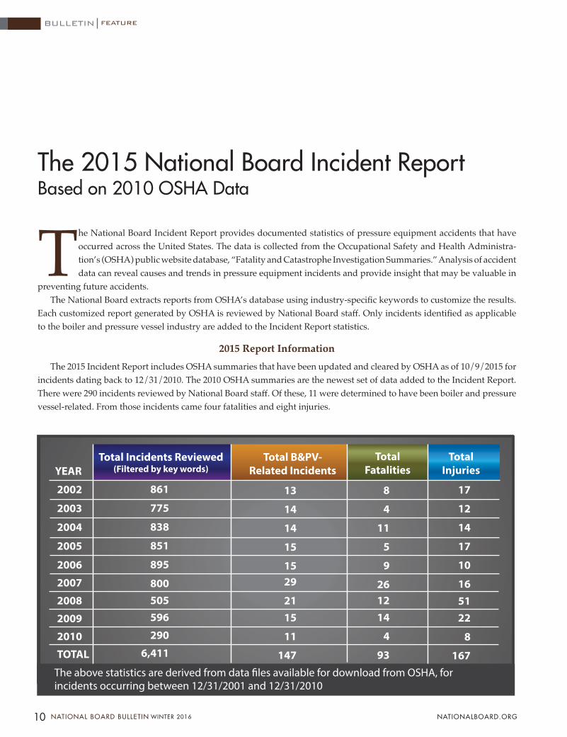
incidents dating back to 12/31/2010. The 2010 OSHA summaries are the newest set of data added to the Incident Report. There were 290 incidents reviewed by National Board staff. Of these, 11 were determined to have been boiler and pressure vessel-related. From those incidents came four fatalities and eight injuries.
The 2015 National Board Incident ReportBased on 2010 OSHA Data
2002
2003
2004
2005
2006
2007
2008
2009
2010
TOTAL
YEARTotal B&PV-
Related IncidentsTotal Incidents Reviewed
(Filtered by key words)Total
FatalitiesTotal
Injuries
The above statistics are derived from data �les available for download from OSHA, for incidents occurring between 12/31/2001 and 12/31/2010
861
775
838
851
895
800505596
290
6,411
13
14
14
15
1529
2115
11
147
8
4
11
5
9
261214
4
93
17
12
14
17
10
165122
8
167
FEATURE
10 NATIONAL BOARD BULLETIN WINTER 2016 NATIONALBOARD.ORG
BULLETIN
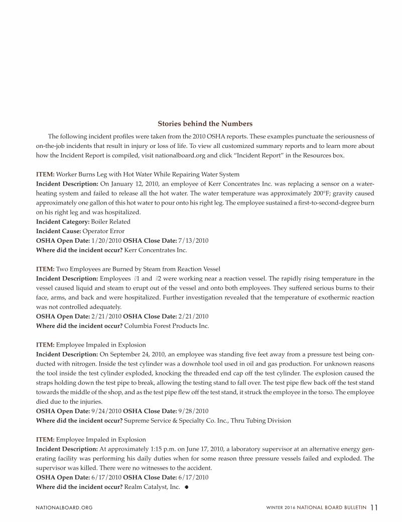
Stories behind the NumbersThe following incident profiles were taken from the 2010 OSHA reports. These examples punctuate the seriousness of
on-the-job incidents that result in injury or loss of life. To view all customized summary reports and to learn more about how the Incident Report is compiled, visit nationalboard.org and click “Incident Report” in the Resources box.
ITEM: Worker Burns Leg with Hot Water While Repairing Water SystemIncident Description: On January 12, 2010, an employee of Kerr Concentrates Inc. was replacing a sensor on a water-heating system and failed to release all the hot water. The water temperature was approximately 200°F; gravity caused approximately one gallon of this hot water to pour onto his right leg. The employee sustained a first-to-second-degree burn on his right leg and was hospitalized.Incident Category: Boiler RelatedIncident Cause: Operator ErrorOSHA Open Date: 1/20/2010 OSHA Close Date: 7/13/2010Where did the incident occur? Kerr Concentrates Inc.
ITEM: Two Employees are Burned by Steam from Reaction VesselIncident Description: Employees #1 and #2 were working near a reaction vessel. The rapidly rising temperature in the vessel caused liquid and steam to erupt out of the vessel and onto both employees. They suffered serious burns to their face, arms, and back and were hospitalized. Further investigation revealed that the temperature of exothermic reaction was not controlled adequately.OSHA Open Date: 2/21/2010 OSHA Close Date: 2/21/2010Where did the incident occur? Columbia Forest Products Inc.
ITEM: Employee Impaled in ExplosionIncident Description: On September 24, 2010, an employee was standing five feet away from a pressure test being con-ducted with nitrogen. Inside the test cylinder was a downhole tool used in oil and gas production. For unknown reasons the tool inside the test cylinder exploded, knocking the threaded end cap off the test cylinder. The explosion caused the straps holding down the test pipe to break, allowing the testing stand to fall over. The test pipe flew back off the test stand towards the middle of the shop, and as the test pipe flew off the test stand, it struck the employee in the torso. The employee died due to the injuries.OSHA Open Date: 9/24/2010 OSHA Close Date: 9/28/2010Where did the incident occur? Supreme Service & Specialty Co. Inc., Thru Tubing Division
ITEM: Employee Impaled in ExplosionIncident Description: At approximately 1:15 p.m. on June 17, 2010, a laboratory supervisor at an alternative energy gen-erating facility was performing his daily duties when for some reason three pressure vessels failed and exploded. The supervisor was killed. There were no witnesses to the accident.OSHA Open Date: 6/17/2010 OSHA Close Date: 6/17/2010Where did the incident occur? Realm Catalyst, Inc.
11 WINTER 2016 NATIONAL BOARD BULLETIN NATIONALBOARD.ORG

FEATURE
Zone Rouge. Does that phrase have an exotic sound? It is French for “red zone.” These days the term Red Zone might point to a football highlights channel, but after World War I it was all about labeling places of high hazard. Zone Rouge signs went up across cratered, lifeless battle zones in Belgium and France, signaling that the government would allow no houses, busi-nesses, or towns to be rebuilt there. For many generations it would remain a place of bizarrely–pitted terrain.
During the 10-month battle around Verdun, France, at least 30 million artillery rounds fell on the landscape, removing hilltops and every tree. Several million shells didn’t explode upon hitting the mud, so their fillings (high explosives or liquefied poison gas) remained intact and very deadly. Hundreds of years will pass before all the Red Zone dangers succumb to weather, corrosion, and bomb-removal squads.
So think of a Red Zone as someplace uninhabitable. This might last only months, or even days. In the worst of the Red Zones, people inside can’t stand to remain, but struggle to get out. Some Red Zones are products of nature, like volcanoes and tsu-namis; of interest here are the technological varieties, such as the accidental discharge of fire-extinguishing gases into a building during maintenance at a federal facility in Idaho. That 1998 Red Zone mishap killed one person and injured 13.
Red Zone – Places of High HazardJAMES R. CHILES
Could your organization have a Red Zone of its own? Think twice before you say “No!” Most cases I see arise out of heedlessness, not criminal negligence or recklessness. Heedless leaders are oblivious to danger signals. They’re convinced that if some bad event hasn’t hap-pened in recent memory, it won’t happen now.
But it can. That’s the message delivered by Nick Morris in a wrenching keynote at the National Board’s 2014 General Meeting in Bellevue, Washington. Nick is a motivational speaker now, but in February 2007 he was a contractor running a small repair crew at a refinery owned by Valero Energy. In Nick’s case, the Red Zone rose out of a combination of factors: the facility’s history of inadequate safety checks, the absence of equipment to handle major emergencies, and old gear that was abandoned in place. Let’s take a closer look at the 15-year chain of events, and many missed opportunities, that led to Nick’s Red Zone.
Valero was fairly new to the refinery busi-ness, having branched out from natural gas distribution into oil refining in the 1980s, then growing quickly through mergers and acqui-sition. By 2005, Valero was refining more oil than any other company in North America, with 16 plants.
One of these was the 170,000-barrel-per-day McKee Refinery near Sunray, Texas, which brings us to Nick Morris’ date with disaster in 2007. The McKee plant covered 5,000 rural acres in the Texas Panhandle, less than an hour’s drive from Amarillo.
James R. Chiles, author of In-viting Disaster and The God Machine , has been writing about technology and history for over 30 years. His work has appeared in Smithsonian, Air & Space, Popular Science, Har-vard, Aviation Week, Mechani-cal Engineering, and Invention & Technology. He maintains a blog called Disaster-Wise.
12 NATIONAL BOARD BULLETIN WINTER 2016 NATIONALBOARD.ORG
BULLETIN
view, followed by the forensic investi-gation. Nick was running a small crew charged with fixing three leaks in a pipe rack. After lunch, the men gathered in the work zone – a narrow alleyway between the pipes, with only one way out – for a quick orientation and safety talk. Just after 2:00 pm, when Nick was coming to the emergency procedures part of the briefing, the men heard a pop followed by the hiss of a high-pressure vapor jet. The source was piping near
It had a sadly colorful history. Started by Shamrock Oil & Gas, the plant began taking natural gas in 1933. In July 1956, while owned by Shamrock-McKee, a gas leak and fire set the contents of a nearby pentane-hexane storage tank to a rolling boil. The intense heat soft-ened the steel of tank walls above the liquid level. The tank burst and set off a fuel-air blast so powerful it severely burned bystanders a quarter-mile away. Industrial firefighters now call this a BLEVE, short for “boiling liquid expanding vapor explosion.” Nineteen volunteer and company firefighters died, making it the third-greatest loss of life among American firefighters until the September 11, 2001, attacks.
The refinery was rebuilt. Valero En-ergy took over from Ultramar Diamond Shamrock in 2002, and Valero paid for a plant upgrade in 2004. But, as events three years later showed, the upgrades didn’t tie up all the loose ends.
The McKee Refinery drew crude oil from pipelines across four states and “cracked” it into gasoline, diesel, aviation fuel, and sulfuric acid. This yielded a tarry residue called pitch, which after some added processing, the refinery sold as asphalt for hot-mix paving machines. It was a Red Zone mishap in the pitch-to-asphalt sector of the McKee plant that sent 14 people to the hospital in 2007 and nearly caused a catastrophic blast. The chain-reaction fire shut the plant down for two months of repairs.
First, a look at what happened on February 16 from Nick Morris’ point of
a tall column called a propane de-asphalting unit, or PDA. It looked like steam, or maybe vapor.
As Nick and his men pulled out, refinery workers yelled the scary news that the leak was propane. Seconds after Nick followed his crew into the clear, the propane cloud found flame down-wind and flashed back to the release point. The fuel-air explosion set Nick on fire from head to toe. Taking short breaths to keep flame out of his lungs,
13 WINTER 2016 NATIONAL BOARD BULLETIN NATIONALBOARD.ORG
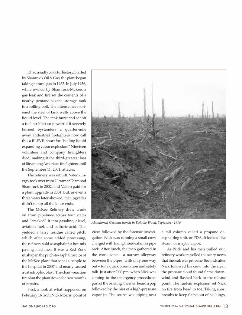
Abandoned German trench in Delville Wood, September 1916

Nick stumbled to the only refuge at hand, a pothole filled with muddy wa-ter. He called to passing workers, who helped him to safety and what would prove a very long road to recovery.
The Chemical Safety Board’s inves-tigation had to wait until all the flames were out in what the company now called the Exclusion Zone. The McKee refinery’s two-month closure triggered
gasoline shortages in Denver. Complet-ing the repairs took almost a year.
What happened? The refinery used propane in large volumes as a solvent to separate the pitch into two streams: a “gas oil” fraction that was suitable for gasoline production, and asphalt for pavement. For this job, the refinery used two tall, cylindrical propane de-asphalt-ing extractors. The plant recycled the
propane back into the extractor, adding a small amount of makeup propane to replace what was lost in the process.
In the web of propane feed lines at ground level was a U-shaped length of steel pipe, 10 inches in diameter, origi-nally installed as part of a mixing station but abandoned in place 15 years before the fire, when workers for the previous owner had sidelined it as unnecessary.
FEATURE
14 NATIONAL BOARD BULLETIN WINTER 2016 NATIONALBOARD.ORG
BULLETIN
Fighting in Delville Wood, "the Devil's Woods." Official British Military drawing, first published in "The Great War" Ed. H.W. Wilson, 1917.

The workers reasoned that if they twisted down gate valves at both ends of the pipe, the length would be sealed from the high-pressure propane feed. Such leftovers are called “dead legs” in the chemical engineering world: intact but inactive. Documents at the refinery had noted this pipe as a dead leg, but company policy didn’t call for dealing with leftovers, so nothing had been done to remove it or even check on its status.
Had anyone taken a skeptical look at the dead leg, they’d have found it was neither sealed nor empty. A piece of steel scrap jammed in one of the valve bodies – what airplane mechanics call foreign object debris – had kept that valve from closing all the way. Thus for more than a decade the dead leg was open to 500 psi propane flowing past the gate valve to the PDA unit; and open to water vapor in the makeup propane – vapor that condensed into water when in contact with cold steel.
A workmanlike hazard assessment would have flagged the well-known risk of frozen pipes that lead to leaks. It would have listed simple remedies, such as removing the pipes, or installing slip blinds to seal off the section, or just run-ning heat traces to prevent ice damage.
None of this was done but even so, nothing visibly bad happened until February 2007, starting with a four-day cold snap. The water trapped at the bottom of the dead leg froze and expanded, cracking steel at the inner radius of an elbow. The weather moder-ated through the morning of February 16. By early afternoon enough ice had melted around the fracture to open a path for high-pressure propane. The ice gave way and propane came screaming out. Then a pipe flange at the base of Extractor No. 2 failed. Now a jet fire was underway, fed by two tons of propane every minute.
This giant blowtorch took aim at a pipe bridge less than a hundred feet away loaded with more petroleum products. These pipes and supports – unprotected by fireproofing – softened, sagged, and broke open. Now there was a new front in the battle: a pool fire. The plant’s emergency operations center triggered sirens for a full retreat.
Next in the chain of events was a cloud of deadly chlorine gas from three overheated cylinders a short walk from the failed pipe bridge. The refinery had been storing this poisonous gas in three one-ton tanks to disinfect process water. Fortunately, responders who came back in hopes of turning manual valves to fight the fires had donned self-contained breathing apparatus (SCBA) gear.
The firefighters couldn’t get to the critical valves. The PDA unit lacked re-motely operated shutoff valves, though the previous owner had identified the need in 1996. Reported the Chemical Safety Board, “However, they were never installed, and the action item was incorrectly closed out as having been completed.” While manual valves at the scene could have shut off propane feeding the fire, the flames made ap-proach to this technological Red Zone impossible.
One nightmare scenario loomed over emergency plans that day, one that could have demolished the entire refinery: the rupture of a 420,000-gallon butane tank less than a hundred yards from the pool fire under the pipe bridge. Firefighters couldn’t get close enough to open deluge monitors and hit the tank walls with cooling water. Even as radiant heat blistered paint from the butane tank, chilly afternoon winds saved the day by redirecting much of the heat elsewhere.
Nick Morris spent months in the hospital and will carry scars the rest
of his life. What lessons can we draw from the second McKee refinery fire, in tribute to him and other burn victims?• Inherent safety: As chemical-
processing expert Trevor Kletz famously said, “What you don’t have, can’t leak.” Instead of deadly chlorine gas as a biocide for its process water, McKee could have used a much safer bleach solution.
• Abandoned (but attached) equip-ment: In a twist on the cliché about memorable people who have died, we could say the “dead leg” pip-ing was “forgotten but not gone.” Process Hazard Assessments shouldn’t ignore dead legs and their potential for leaks and ice damage.
• Valves: Is anyone checking on leaks and other risks? Signed paperwork is no proof that vital work has been completed.
• Evacuation: Given the high risk of catastrophe during the 2007 fire at McKee, the plant’s emergency operations center was smart to evacuate the entire plant within 15 minutes, and the retreat was well executed.
• Think remotely: If there’s a big fire in Sector B-5, are we going to have to charge into the mouth of hell to control it, or can we stay back and activate remote shutoff valves and deluge guns?
Remember Nick Morris: Nick’s excru-ciating hospital stays for reconstruction and skin grafts stretched more than a year. Yet he says that the fire at McKee was more a good day for him than a bad day. He walked out of the Red Zone, leaving truck and tools in the flames but bearing a life-saving message: “Every job is a self-portrait of the person who did it.”
What does your portrait look like?
15 WINTER 2016 NATIONAL BOARD BULLETIN NATIONALBOARD.ORG
May 9 - 13, 2016
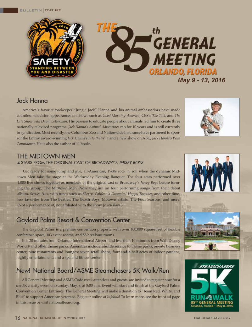
Gaylord Palms Resort & Convention CenterThe Gaylord Palms is a premier convention property with over 400,000 square feet of flexible
conference space, 103 event rooms, and 58 breakout rooms.It is 20 minutes from Orlando International Airport and less than 10 minutes from Walt Disney
World® and other theme parks. Amenities include: shuttle service to theme parks; on-site business center, nine restaurants and lounges; seven retail shops; four-and-a-half acres of indoor gardens; nightly entertainment; and a spa and fitness center.
New! National Board/ASME Steamchasers 5K Walk/RunAll General Meeting and ASME Code week attendees and guests are invited to register now for a
free 5K charity event on Sunday, May, 8, at 8:00 a.m. Event will start and finish at the Gaylord Palms Convention Center Entrance. The General Meeting will make a donation to "Team Red, White, and Blue" to support American veterans. Register online at Infolink! To learn more, see the front ad page in this issue or visit nationalboard.org.
16 NATIONAL BOARD BULLETIN WINTER 2016 NATIONALBOARD.ORG
BULLETIN FEATURE
Jack HannaAmerica’s favorite zookeeper “Jungle Jack” Hanna and his animal ambassadors have made
countless television appearances on shows such as Good Morning America, CBS’s The Talk, and The Late Show with David Letterman. His passion to educate people about animals led him to create three nationally televised programs. Jack Hanna’s Animal Adventures ran for 10 years and is still currently in syndication. Most recently, the Columbus Zoo and Nationwide Insurance have partnered to spon-sor the Emmy award-winning Jack Hanna’s Into the Wild and a new show on ABC, Jack Hanna’s Wild Countdown. He is also the author of 11 books.
THE MIDTOWN MEN 4 STARS FROM THE ORIGINAL CAST OF BROADWAY’S JERSEY BOYS
Get ready for some jump and jive, all-American, 1960s rock 'n' roll when the dynamic Mid-town Men take the stage at the Wednesday Evening Banquet! The four stars performed over 1,000 live shows together as members of the original cast of Broadway’s Jersey Boys before form-ing the group, The Midtown Men. Now they are on tour performing songs from their debut album, Sixties Hits, with tunes such as Sherry, California Dreamin,’ Happy Together, and other time-less favorites from The Beatles, The Beach Boys, Motown artists, The Four Seasons, and more. (Not a performance of, not affiliated with the show Jersey Boys.)

May 9 - 13, 2016
Monday, May 9Opening Session
10:15 a.m. REMARKS Jack Hanna & Friends
General Session
1:00 p.m. STATISTICAL AND LOSS-BASED TRAINING Vance Murphy, RISK CONSULTANT
ZURICH NORTH AMERICA INSURANCE
1:30 p.m. THE NATIONAL BOARD INSPECTION CODE Gary Scribner, MANAGER OF TECHNICAL SERVICES NATIONAL BOARD OF BOILER AND PRESSURE VESSEL INSPECTORS 2:00 p.m. ABMA - TURNING CHALLENGES INTO OPPORTUNITIES Scott Lynch, PRESIDENT & CEO AMERICAN BOILER MANUFACTURERS ASSOCIATION 2:30 p.m. BREAK
2:45 p.m. REMARKS Denis DeMichael, Chairman, ASME Subcommittee on
Safety Valve Requirements SENIOR CONSULTANT, THE CHEMOURS COMPANY
3:15 p.m. INVITED
3:45 p.m. INVITED
General Meeting Notices
• Attendees and guests are encouraged to dress in a business-casual style for all hotel events except the Wednesday banquet (where ties and jackets will be the evening attire).
• Distribution of any and all literature other than informational materials published by the National Board and ASME is strictly prohibited at the General Meeting.
• To obtain a preregistration discount of $50, all forms and fees must be received by April 25.
• On-Site Registration Desk Hours:
Sunday, May 8 . . . . 9:00 a.m. - 2:00 p.m. Monday, May 9 . . . .8:00 a.m. - 10:00 a.m. Tuesday, May 10 . . . . 8:00 a.m. - 10:00 a.m.
• General Meeting Registration is required in order to receive the special $199 room rate at the Gaylord Palms Resort and Convention Center.
Reminder
General Meeting details can also be found on InfoLink! located on the National Board website at nationalboard.org.
ASME Boiler and Pressure Vessel Code Meetings
• Meetings are scheduled all week.
• Check hotel information board for locations and times.
• Meetings are open to the public.
85th GENERAL MEETING PRELIMINARY PROGRAM
The National Board of Boiler and Pressure Vessel Inspectors&
ASME Boiler and Pressure Vessel Committee
17 WINTER 2016 NATIONAL BOARD BULLETIN NATIONALBOARD.ORG

GENERAL MEETING GUEST TOURS
Monday, May 9 Backstage Tour of Wild Florida, 1:00 p.m. – 5:00 p.m.
After Jungle Jack Hanna shares his stories of animal lore at the Opening Session, guests will travel to Wild Florida – a wildlife park located on Lake Cypress in the headwaters of the Florida Everglades.
Guests will enjoy a rare opportunity to visit “backstage” with over 200 animals on display, including zebras, sloths, lemurs, bobcats, and other exotic species. A walk-in aviary features birds from all over the world. Knowledgeable hosts will take guests on a leisurely walking tour, pointing out the habits and history of each animal for the ultimate personal interaction.
And what tour of a Florida preserve would be complete without alligators? Guests will get an intimate look at alligators in a controlled habitat and have a chance to actually hold one!
Whatever your pleasure, bring your camera or cellphone. You may never get to see wildlife this close again!Complimentary refreshments provided. Guests are advised to bring sunscreen, sunhat, camera, and
comfortable walking shoes. This tour requires a modest amount of walking.
Tuesday, May 10 Triad Tuesday, 9:00 a.m. – 4:15 p.m.
This outing is somewhat different from what our guests have come to expect. For starters, we’re locking them in a room and throwing away the key! Literally.
After dividing the group into two, the first will visit Escapology: a real-life escape game challenging teams to find clues and solve puzzles to free themselves from a locked room within a limited amount of time.
The second group will visit I-Drive 360, a chic $250-million entertainment destination. The centerpiece is the Orlando Eye, a 400-foot-tall observation wheel featuring panoramic views during a 25-minute ride. Guests also can take selfies with celebrities at Madame Tussaud’s wax museum, or view beautiful sea crea-tures in an immersive 360-degree ocean tunnel at SEA LIFE Aquarium.
Both groups will meet for a Cuban-themed luncheon at the famed Cuba Libre restaurant. Afterwards, groups will trade attractions and then return to the hotel in time for evening activities.
Guests are advised to bring sunscreen, sunhat, camera, and comfortable walking shoes. This tour requires a modest amount of walking.
Wednesday, May 11 Kennedy Space Center Tour, 8:00 a.m. – 3:00 p.m.
At 8 o’clock sharp, participants will be transported to NASA’s Kennedy Space Center to enjoy a full day of self-guided tours.
With many compelling exhibits to choose from (including a 45-minute bus tour departing every 15 minutes), participants are encouraged to visit the KSC website and plan activities in advance of the outing.
One must-see exhibit is the new 90,000-square-foot “Space Shuttle Atlantis” facility. A brief movie tells the dramatic story of NASA’s 30-year space shuttle program before visitors are ushered into the expansive complex where the Atlantis is suspended from the ceiling, rotated 43.21 degrees with payload doors open and its robotic arm extended – just as it would appear when undocked from the International Space Station.
Also included: over 60 interactive exhibits and high-tech simulators; the Shuttle Launch Experience (a realistic launch simulator); and the solemn Challenger memorial.
A buffet lunch will be served at the Debus Center to allow everyone the opportunity to visit as many of the attractions as possible.
Participants are advised to bring sunscreen, sunhat, camera, and comfortable walking shoes. This tour requires a modest amount of walking.
NOTE: Attendees are not permitted to attend the Monday or Tuesday tours intended for designated guests. This policy is strictly enforced. All tours depart from Convention Center Porte Cochere.
18 NATIONAL BOARD BULLETIN WINTER 2016 NATIONALBOARD.ORG
BULLETIN FEATURE
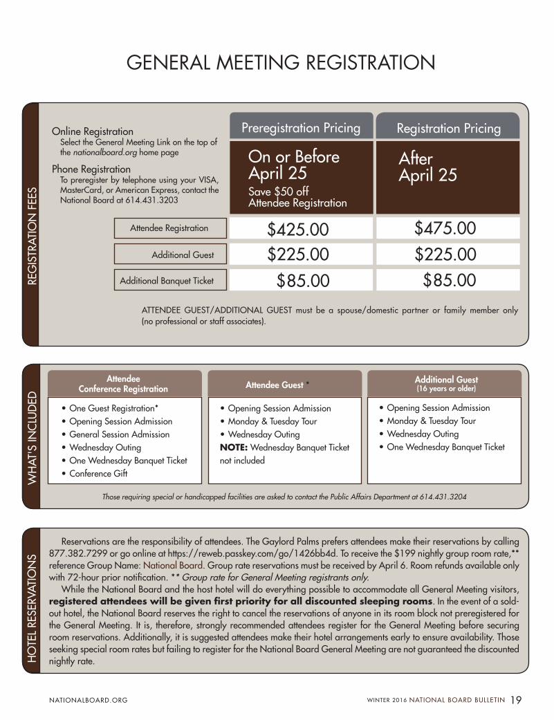
GENERAL MEETING REGISTRATION
Preregistration Pricing Registration Pricing
Attendee Registration
$85.00
$225.00$85.00
$225.00
$475.00$425.00Additional Guest
Additional Banquet Ticket
On or Before April 25Save $50 off Attendee Registration
After April 25
ATTENDEE GUEST/ADDITIONAL GUEST must be a spouse/domestic partner or family member only (no professional or staff associates).
• One Guest Registration*• Opening Session Admission• General Session Admission• Wednesday Outing• One Wednesday Banquet Ticket• Conference Gift
• Opening Session Admission• Monday & Tuesday Tour• Wednesday OutingNOTE: Wednesday Banquet Ticket not included
• Opening Session Admission• Monday & Tuesday Tour• Wednesday Outing• One Wednesday Banquet Ticket
Those requiring special or handicapped facilities are asked to contact the Public Affairs Department at 614.431.3204
Reservations are the responsibility of attendees. The Gaylord Palms prefers attendees make their reservations by calling 877.382.7299 or go online at https://reweb.passkey.com/go/1426bb4d. To receive the $199 nightly group room rate,** reference Group Name: National Board. Group rate reservations must be received by April 6. Room refunds available only with 72-hour prior notification. ** Group rate for General Meeting registrants only.
While the National Board and the host hotel will do everything possible to accommodate all General Meeting visitors, registered attendees will be given first priority for all discounted sleeping rooms. In the event of a sold-out hotel, the National Board reserves the right to cancel the reservations of anyone in its room block not preregistered for the General Meeting. It is, therefore, strongly recommended attendees register for the General Meeting before securing room reservations. Additionally, it is suggested attendees make their hotel arrangements early to ensure availability. Those seeking special room rates but failing to register for the National Board General Meeting are not guaranteed the discounted nightly rate.
AttendeeConference Registration Attendee Guest * Additional Guest
(16 years or older)
REG
ISTR
ATIO
N F
EES
WH
AT'S
INC
LUD
ED
HO
TEL
RESE
RVAT
ION
S
Online Registration Select the General Meeting Link on the top of the nationalboard.org home page
Phone Registration To preregister by telephone using your VISA, MasterCard, or American Express, contact the National Board at 614.431.3203
19 WINTER 2016 NATIONAL BOARD BULLETIN NATIONALBOARD.ORG

PRESSURE RELIEF REPORT
be needed periodically. A welded inlet pressure relief valve is a solution for both problems.
In pressure vessel and piping applica-tions, the need for a welded installation comes from a similar need to maintain leak-tightness in a system by avoid-ing mechanical joints. The overriding consideration is the environmental and health safety concerns of the wide range of flammable, toxic, or polluting chemicals used in industry. Every mechanical joint that can be avoided is one less potential source of leakage. Installation can be done with a butt-welded inlet. A socket weld is often used for small valves that would normally be threaded.
What organization is appropriate to perform the installation weld?
A pressure relief valve manufacturer’s job ends with the inlet connection of the pressure relief valve, and does not include its installation. The manufacturer provides appropriate weld preparation for the valve as specified by the customer. For a valve to be installed with a socket weld, common practice is to supply the valve with the pipe stub-welded to it (that weld is the valve manufacturer’s responsibility) but the final socket weld at the other end of the pipe is the responsibility of another organization.
For new construction of boilers, the re-sponsible party is the boiler manufacturer or assembler (with an ASME Certificate to use ASME Certification Mark "S" or "A" Designators) or an ASME pressure piping certificate holder with the “PP” Designa-tor (Reference: Section I, par. PG-58). If a new or repaired valve is being installed on an existing boiler, the weld must be done in accordance with jurisdictional requirements, which for most states and
Welded Installation of Pressure Relief ValvesBY JOSEPH F. BALL, P.E., DIRECTOR, PRESSURE RELIEF DEPARTMENT
provinces requires a National Board “R” stamp holder [Reference: NBIC Part 3, par. 1.1, and 3.3.3(t)].
For the construction of a new pressure vessel, the manufacturer could make the pressure relief valve installation weld. This becomes one of the welds it is re-sponsible for as part of the new equipment manufacturing process. The weld also could be performed in the field by the user. At that time the responsibility for the weld becomes subject to the requirements of the local jurisdiction, and in most cases prob-ably would fall under the requirements of one of the pressure piping standards, such as ASME B31.3.
Welding Process Concerns
Confusion as to who is responsible for completing the installation process occurs when the valve itself is affected by that process. Valves installed with a socket weld configuration (assuming the pipe itself has been welded to the valve body during the new valve manufacturing pro-cess), should not be affected by the weld-ing process if a suitable length of pipe is provided and the heat is monitored during welding. The concern is that if heat from welding can significantly affect the valve seating area, the seats of a metal seated valve may warp. If the valve contains soft goods such as O-rings, plastic seats, or gaskets, those could be damaged by excessive heat. If the valve body cannot be protected from the effects of the welding heat, the valve would need to be disas-sembled before the weld is performed, and then reassembled and tested after the weld is completed.
The weld configuration for high-pressure steam valves is a butt weld where the welded material may be up to several inches thick. Because of the thickness
The topics that are addressed in this Pressure Relief Re-port usually pertain to the activities of pressure relief valve manufacturing and
repair work. This article, however, reaches outside the scope of those activities to the topic of welded pressure relief valve installations on boilers, pressure vessels, or piping systems.
As we will see in references from the ASME Boiler and Pressure Vessel Code (ASME Code) and National Board Inspec-tion Code (NBIC), this welding must be performed by qualified organizations that are NOT the valve manufacturer or valve repair organization. However, it should be noted that using welding for valve installations may affect the valve, and in certain cases, the manufacturer or repair firm also needs to be involved in the installation process.
Welded Installations
Welded installations are used when there is a need to avoid a mechanical joint on a pressure-retaining item (PRI). For high-pressure boiler applications, flanged joints present an opportunity for high-pressure steam leaks, which are an obvious hazard to personnel and equip-ment. When superheated steam is present, an invisible steam leak can be deadly. If such a leak occurs, an emergency exit pro-cedure recommends workers hold a long stick (such as a broom) in front of them, so they do not walk into the deadly high-temperature and high-velocity stream that cannot be seen.
Flanged joints also present a mainte-nance challenge because gasket changes and monitoring of bolting torques may
20 NATIONAL BOARD BULLETIN WINTER 2016 NATIONALBOARD.ORG
BULLETIN

and the materials used, pre-heat and inter-pass temperature requirements are usually present. The final configuration will often also require post-weld heat treatment. One process followed is that the manufacturer supplies the valve in two parts, one of which is the inlet por-tion of the valve, with the remaining top part of the valve supplied as a separate assembly. The valve also may be supplied as a unit and disassembled for welding at the installation site. The valve body is welded to the boiler. Then the valve seats are inspected and lapped or machined as required. The valve is then reassembled and retested. This test is required because
even though the valve originally may have been tested by the manufacturer, the final set pressure cannot be guaranteed after the valve has been taken apart. Also, valves that are installed by welding often have set pressures which exceed factory test capabilities, and final setting can be done on the boiler only at the field site, either by using a lift assist device (LAD) or by testing at full pressure.
A further complication in the process for welding a valve to a pressure-retaining item comes after the weld has been com-pleted. A pressure test is required as a quality control check for the performance of the weld. The test pressure for new
boiler construction is 1.5 times the MAWP, which is above the pressure relief valve set pressure. For repair activities, the pressure is agreed upon between the authorized inspector and the repair organization.
To keep the pressure relief valves from opening, valves are either gagged, or some have provisions for installing a hydrostatic test plug (often called a “hydro plug”). The plug is installed between the disk and nozzle of the valve, and compresses the spring enough to keep the valve closed under the hydro test pressure. Since it is installed internally in the valve, it must be disassembled after the pressure test is completed to remove the plug. Then it is reassembled and tested. Removal of the hydro plug, reassembly, and final testing usually is done all at one time.
The quality system for the boiler or pressure vessel manufacturer or “R” stamp repair certificate holder does not include pressure relief valve construction or repair activities. Therefore, all activities related to valve assembly, lapping or machining of the valve seats, and testing of the com-pleted valve, are the responsibility of the manufacturer for a new valve, or a repair organization if the valve is being serviced.
Since multiple parties can be involved when a pressure relief valve is installed by welding, coordination among all parties is essential to ensure that all code-required activities are properly completed before the equipment goes into service. Evidence of final completion is the application of the ASME Certification mark and manu-facturer’s seals, or a “VR” nameplate and repair organization’s seals.
The authorized inspectors involved need to keep in mind the responsibilities of the different organizations so they can confidently sign off on the installation when it is complete. Those responsibilities are divided because each organization has its own quality program, personnel qualifications, and experience related to the task it is performing.
21 WINTER 2016 NATIONAL BOARD BULLETIN NATIONALBOARD.ORG
Phot
o co
urte
sy o
f Nat
iona
l Tec
hnic
al S
yste
ms.
Imag
e co
urte
sy o
f Far
ris E
ngin
eeri
ng
Div
isio
n of
Cur
tiss-
Wri
ght F
low
Con
trol
Cor
pora
tion
VALVE CONSTRUCTION WELDS BY VALVE MANUFACTURER
INSTALLATION WELDS BY VESSEL MANUFACTURER OR USER
INSTALLATION WELDS BY VESSEL MANUFACTURER OR USER
Welding nipple version of 2700 series valve

FEATURE
Table 1: Section I Power Boiler Requirements for Boiler Water Level Gage Glasses (excluding electrode-type electric boilers and boilers having no fixed water level)
Gage Glass(es) Visible to the Operator At least one Gage Glass Not Visible to the Operator
Boi
lers
Ove
r 400
psi
Two Operational
Gage Glasses
or One Operational Gage Glass in
Service and Two Independent
Remote Water Level Indicators
or One Operational Gage Glass shut off, but ready for service, and Two
Independent Remote Water
Level Indicators
One Gage Glass and a Fiber Optics
Cable to Transmit the Water Level
Image
or One Gage Glass and a Mirror
System to Transmit the Water Level
Image
or One Gage Glass, One Independent
Remote Water Level Indicator,
and One Independent Continuous
Transmission of a Gage Glass Water
Level Image
or One Gage Glass and
Two Independent Remote Water Level
Indicators
or One Gage
Glass and Two Independent Continuous
Transmissions of a Gage Glass
Water Level Image
Boi
lers
400
psi
and
Les
s At Least One Gage Glass Which Must be In Service at All Times
A Gage Glass with a Fiber Optics Cable
to Transmit the Water Level
Image
or A Gage Glass with a Mirror System to
Transmit the Water Level
Image
or A Gage Glass with
an Independent Remote Water Level Indicator
and One Independent Continuous
Transmission of a Gage Glass Water
Level Image
or A Gage Glass and Two Independent
Remote Water Level Indicators
or A Gage Glass
and Two Independent Continuous
Transmissions of the Gage Glass
Water Level Image
PG-60.1.1 PG-60.1.1.1
It should be noted that NBIC Part I, 2.8.1(h) and (k) requires one gage glass for boilers 400 psi and below, and two gage glasses for boilers over 400 psi and does not allow alternatives as in ASME Section I.
Table 2: Section IV Steam Heating Boiler Water Level Gage Glass Requirements
Minimum Requirement Alternate Minimum Requirement
One or more Gage GlassesA Gage Glass Installed and Operable (but may be shut off)
Plus a Water Level Indicator Using an Indirect Sensing Method
HG-603 (a) HG-603 (f)
It should be noted that NBIC Part I, 3.8.1.2(a) requires one or more gage glasses and does not allow alternatives as in ASME Section IV.
22 NATIONAL BOARD BULLETIN WINTER 2016 NATIONALBOARD.ORG
BULLETIN
Water Level Indicators BY TIM GARDNER, SENIOR STAFF ENGINEER
Steam boilers are used all around us for a variety of applica-tions. Inspectors and operators should be cognizant of the code requirements for their instrumentation. One of the most
important parameters in the safe operation of a steam boiler is the water level. If a boiler’s water level falls below the manufacturer’s minimum design level, metal surfaces that depend on the cooling effect of a water covering can be exposed, which can lead to severe or catastrophic damage.
For this reason, both Section I and Section IV of the ASME Boiler and Pressure Vessel Code (ASME Code), as well as the National Board Inspection Code (NBIC), list requirements for level gages. These requirements, including any jurisdictional requirements, should be reviewed to ensure that the rules are properly understood and followed. These rules are especially important to the inspector who is tasked with the important role of ensuring that boilers are safe
and catastrophic failures due to improper water levels do not occur. This article reviews the most common types of water level
gages, how they function, and the type of boiler they are required to be used on. Since inspectors need to know the various code re-quirements associated with water level indicators, this article also seeks to review and summarize those requirements. A reference guide of specific rules associated with various types of boilers is provided on page 25.
To get started, following are explanations of boiler water level gage glass requirements for power boilers (Table 1) and steam heating boilers (Table 2). These tables portray what is expressed in Section I and Section IV ASME Code paragraphs. The tables provide the same information in an easy-to-understand format since the multiple code paragraphs regarding water level indica-tors can be quite confusing.

With a basic understanding of gage requirements, let’s take a closer look at specific water level gages. In order for inspectors to confirm that a boiler has the required water level gages or indicators, they must know something about them. Consider the following types of common indicators.
Figure 1: A Typical Tubular-Type Level Gage
Bull’s-Eye Gages
A second type of gage glass allowed on some very specific small boilers is the bull’s-eye type. A bull’s-eye gage is essentially a small round glass window within a metal body resembling a pipe plug that is threaded into the wall of the boiler. Bull’s-eye gages are allowed on ASME Section IV steam heating boilers under 10 inches internal vertical height. For ASME Section I boilers, bull’s-eye gages are allowed on small miniature boilers operating in a closed system where insufficient space exists for usual types of water gage glasses. Obviously, the range of the level that can be observed on this gage is quite small, so place-ment is critical. For ASME Section IV steam heating boilers, it needs to be large enough to show both normal and low-water cut-off levels.
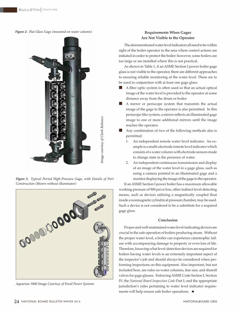
Flat Glass Gages
The Flat Glass Gage as shown in Figure 2 is sometimes used for boilers and is mandated in ASME Section I for organic fluid vaporizers. The flat glass gage has a rectangular (usually with rounded ends) piece of tempered glass that is sandwiched in and bolted between two pieces of steel. The glass gives a view of the fluid level in a chamber in the rear half of the gage that is connected to the drum, boiler, or water column, much like the tubular gage described earlier. In the reflex version of this gage the inner glass surface is shaped as a series of prisms which are designed to refract the light for better distinction between the liquid and vapor.
Multiport Gages
For higher-pressure boilers, a multiport design such as that shown in Figure 3 is employed. These gages typically consist of a body with multiple openings with round tempered glass ports that are protected from the steam by mica discs. To better see the level in ported gage glasses, an illuminator attachment is required, which puts paired red and green lights on the back side of the gage. The different refractive properties of the water and steam allow only the red light on the front of the gage when steam or air is present and green light when water is present. The refractive angle determines which light becomes visible behind the port. The end result is a distinct water level with green in the ports having water.
23 WINTER 2016 NATIONAL BOARD BULLETIN NATIONALBOARD.ORG
Tubular Level Gages
One of the simplest types of water level gage is the tubular type, as shown in Figure 1. This type of gage consists of a verti-cal glass tube that is connected above the expected water level for the steam connection and below the expected water level for the water connection on the steam drum or boiler shell. In most cases the connections for this and other types of level gages or instruments are to a water column, which in turn is attached to the boiler. The water column serves to reduce turbulence of the boiler water, which allows a more accurate and steady boiler level determination in the gage. Guards such as rod guards or protective shields such as a channel are required for ASME Section IV steam heating electric boilers of 100 gallons or less capacity equipped with a tubular gage or any ASME Section I electric boiler with a tubular gage.
FEATURE
Figure 3: Typical Ported High-Pressure Gage, with Details of Port Construction (Shown without illuminator)
Imag
e co
urte
sy o
f Cla
rk-R
elian
ce
Aquarian 3000 Image Courtesy of Fossil Power Systems
Figure 2: Flat Glass Gage (mounted on water column) Requirements When Gages Are Not Visible to the Operator
The aforementioned water level indicators all need to be within sight of the boiler operator in the area where control actions are initiated in order to protect the boiler; however, some boilers are too large or are installed where this is not practical.
As shown in Table 1, if an ASME Section I power boiler gage glass is not visible to the operator, there are different approaches to ensuring reliable monitoring of the water level. These are to be used in conjunction with at least one gage glass:• A fiber optic system is often used so that an actual optical
image of the water level is provided to the operator at some distance away from the drum or boiler.
• A mirror or periscope system that transmits the actual image of the gage to the operator is also permitted. In this periscope-like system, a mirror reflects an illuminated gage image to one or more additional mirrors until the image reaches the operator.
• Any combination of two of the following methods also is permitted:1. An independent remote water level indicator. An ex-
ample is a multi-electrode remote level indicator which consists of a water column with electrode sensors made to change state in the presence of water.
2. An independent continuous transmission and display of an image of the water level in a gage glass, such as using a camera pointed to an illuminated gage and a monitor displaying the image of the gage to the operator.
If an ASME Section I power boiler has a maximum allowable working pressure of 900 psi or less, other indirect level-detecting means, such as devices utilizing a magnetically coupled float inside a nonmagnetic cylindrical pressure chamber, may be used. Such a device is not considered to be a substitute for a required gage glass.
Conclusion
Proper and well-maintained water level-indicating devices are crucial in the safe operation of boilers producing steam. Without the proper water level, a boiler can experience catastrophic fail-ure with accompanying damage to property or even loss of life. Therefore, knowing what level-detection devices are required for boilers having water levels is an extremely important aspect of the inspector’s job and should always be considered when per-forming inspections on this equipment. Also important, but not included here, are rules on water columns, line size, and shutoff valves for gage glasses. Enforcing ASME Code Section I, Section IV; the National Board Inspection Code Part I; and the appropriate jurisdiction’s rules pertaining to water level indicator require-ments will help ensure safe boiler operations.
24 NATIONAL BOARD BULLETIN WINTER 2016 NATIONALBOARD.ORG
BULLETIN
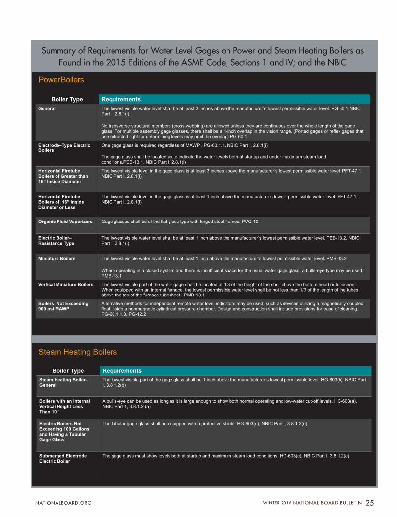
Boiler Type RequirementsGeneral The lowest visible water level shall be at least 2 inches above the manufacturer’s lowest permissible water level. PG-60.1,NBIC
Part I, 2.8.1(j)
No transverse structural members (cross webbing) are allowed unless they are continuous over the whole length of the gage glass. For multiple assembly gage glasses, there shall be a 1-inch overlap in the vision range. (Ported gages or reflex gages that use refracted light for determining levels may omit the overlap) PG-60.1
Electrode–Type Electric Boilers
One gage glass is required regardless of MAWP , PG-60.1.1, NBIC Part I, 2.8.1(i)
The gage glass shall be located as to indicate the water levels both at startup and under maximum steam load conditions,PEB-13.1, NBIC Part I, 2.8.1(i)
Horizontal Firetube Boilers of Greater than 16” Inside Diameter
The lowest visible level in the gage glass is at least 3 inches above the manufacturer’s lowest permissible water level. PFT-47.1, NBIC Part I, 2.8.1(l)
Horizontal Firetube Boilers of 16” Inside Diameter or Less
The lowest visible level in the gage glass is at least 1 inch above the manufacturer’s lowest permissible water level. PFT-47.1, NBIC Part I, 2.8.1(l)
Organic Fluid Vaporizers Gage glasses shall be of the flat glass type with forged steel frames. PVG-10
Electric Boiler– Resistance Type
The lowest visible water level shall be at least 1 inch above the manufacturer’s lowest permissible water level. PEB-13.2, NBIC Part I, 2.8.1(i)
Miniature Boilers The lowest visible water level shall be at least 1 inch above the manufacturer’s lowest permissible water level. PMB-13.2
Where operating in a closed system and there is insufficient space for the usual water gage glass, a bulls-eye type may be used. PMB-13.1
Vertical Miniature Boilers The lowest visible part of the water gage shall be located at 1/3 of the height of the shell above the bottom head or tubesheet. When equipped with an internal furnace, the lowest permissible water level shall be not less than 1/3 of the length of the tubes above the top of the furnace tubesheet. PMB-13.1
Boilers Not Exceeding 900 psi MAWP
Alternative methods for independent remote water level indicators may be used, such as devices utilizing a magnetically coupled float inside a nonmagnetic cylindrical pressure chamber. Design and construction shall include provisions for ease of cleaning. PG-60.1.1.3, PG-12.2
Boiler Type RequirementsSteam Heating Boiler–General
The lowest visible part of the gage glass shall be 1 inch above the manufacturer’s lowest permissible level. HG-603(b). NBIC Part I, 3.8.1.2(b)
Boilers with an Internal Vertical Height Less Than 10”
A bull’s-eye can be used as long as it is large enough to show both normal operating and low-water cut-off levels. HG-603(a), NBIC Part 1, 3.8.1.2 (a)
Electric Boilers Not Exceeding 100 Gallons and Having a Tubular Gage Glass
The tubular gage glass shall be equipped with a protective shield. HG-603(e), NBIC Part I, 3.8.1.2(e)
Submerged Electrode Electric Boiler
The gage glass must show levels both at startup and maximum steam load conditions. HG-603(c), NBIC Part I, 3.8.1.2(c)
Power Boilers
Steam Heating Boilers
Summary of Requirements for Water Level Gages on Power and Steam Heating Boilers as Found in the 2015 Editions of the ASME Code, Sections 1 and IV; and the NBIC
25 WINTER 2016 NATIONAL BOARD BULLETIN NATIONALBOARD.ORG

COVER STORY
26 NATIONAL BOARD BULLETIN WINTER 2016 NATIONALBOARD.ORG
BULLETIN COVER STORY

(Chart does not include all categories of violations for burner management.)
The National Board/ASME General Meeting is unique in a variety of aspects, perhaps the most unusual of which is the extraordinary annual collaboration of two renowned nonprofit organizations spanning a period of over eight decades.
Genesis of the General Meeting – which began in 1921 – can be traced back to a 1910 catastrophe at the American Sheet and Tin Plate Company in Canton, Ohio. The failure of three boilers was the result of cold water being introduced into one of the overheated boilers. Of the 100 workers in that building, 17 were killed and another 50 were injured.
At the time, Ohio had no boiler laws. Consequently, it was known as a dumping ground for old boilers brought in from surrounding states. The following year, the Ohio General Assembly passed legislation requiring inspection of boilers. In 1913, the state formed the Industrial Commission of Ohio, which is still the agency responsible for inspec-tion of pressure equipment.
Inspiration behind the General Meeting may have started in August of 1916 when Ohio Chief Inspector C.O. Myers convened a meeting of Ohio boiler inspectors for what was called the First Ohio Boiler Inspectors Convention in Columbus. (It is not known whether there was a second Ohio Boiler Inspectors convention or subsequent meetings. It can be deduced, however, that reference to the “first” convention suggested gatherings to come.)
It generally happens every spring. And so it has for 84 years. Come May, it will be 85.
Ohio Chief Inspector C.O. Myers, who was instrumental in developing a national organization of jurisdiction inspectors.
BY PAUL BRENNAN, DIRECTOR OF PUBLIC AFFAIRS
27 WINTER 2016 NATIONAL BOARD BULLETIN NATIONALBOARD.ORG

Like today’s General Meeting, the format con-sisted of opening session remarks, presentations, banquet, and a tour. The stark difference was in the number of participants: approximately 50 in-spectors and their spouses at the 1916 gathering as opposed to as many as 750 during more recent General Meetings.
The Ohio convention took place on Thursday and Friday, August 17 and 18, at the Ohio State House of Representatives. At 10 a.m., the meeting was called to order by the convention chairman and chief deputy for the Ohio division of boiler inspection, J. C. Callery. Presentation titles included “Duties of a Boiler Inspector,” “Necessity of Boiler Inspection Codes,” “Advantages of Uniform Boiler Inspection Code,” and “Why Not Preparedness Against Accidents?” A banquet for participants and their guests was held Thursday evening.
Friday morning featured additional technical discussions including a presentation identified as “MOVING PICTURES – From Ore to Finished Pipe.” An afternoon tour for all attendees consisted of a car caravan for a “visit to the Ohio State Peni-tentiary and other points of interest.”
Concerned about disparate codes and stan-dards employed throughout the country, Chief
Inspector C.O. Myers called a meeting in Decem-ber of 1919 of North America’s chief inspectors to discuss creating an organization that would bring together all jurisdiction officials to create a connec-tion through which codes and standards could be assimilated among the various jurisdictions. And thus was created The National Board of Boiler and Pressure Vessel Inspectors.
Given the success of the Ohio inspectors’ convention, Myers launched an effort to gather all key North American constituent groups at one meeting, including all jurisdiction inspectors,
Chairman Scott lost no time at the beginning of the meeting to explain objectives: “This meeting has been called with two objectives in view. First, that those of us who are charged with the safety of boilers may become better acquainted, and secondly for educational purposes.”
The first meeting of Ohio boiler inspection officials took place August 17 and 18, 1916, in Columbus, Ohio.
Guest speaker Charlton Heston at the 1996 General Meeting
28 NATIONAL BOARD BULLETIN WINTER 2016 NATIONALBOARD.ORG
BULLETIN COVER STORY

1916 Ohio boiler inspectors convention brochure and lapel pin
Guest speaker Don Shula at the 2005 General Meeting
American Society of Mechanical Engineers boiler code officials, and influential boiler companies and organizations.
The first General Meeting in 1921 was a three-day event which convened at 10 a.m. at the Hotel Statler in Detroit on Wednesday, February 2. Detroit was chosen as host city because its central location allowed participation of industry professionals traveling across the country. Fifty-six people in attendance included members of the upstart National Board and the ASME Boiler Code Committee. Among the jurisdictions rep-resented by National Board members were: New Jersey, Pennsylvania, Ohio, California, Michigan, Missouri, New York, Oklahoma, Oregon, Rhode Island, Chicago, Erie (Pennsylvania), Kansas City (Missouri), Nashville, St. Louis, Seattle, Allegheny County (Pennsylvania), Ontario (Canada), and New Glasgow (Canada).
The first day was devoted to presentations by individuals from several organizations influential in the pressure equipment industry of that era: Dr. D.S. Jacobus, acting chairman of the Ameri-can Society of Mechanical Engineers Boiler Code Committee; Charles E. Gorton, chairman of the American Uniform Boiler Law Society; C.W. Bis-sell, dean of the Michigan Agricultural College and chairman of the Michigan Board of Boiler Rules; J.C. McCabe, commissioner of the City of Detroit and
chief inspector of Boilers for the State of Michigan; E.R. Fish, vice president of the Heine Safety Boiler Company; S.F. Jeter, chief engineer of the Hartford Steam Boiler Inspection and Insurance Company; F.W. Herendeen, secretary of the National Boiler and Radiator Manufacturers Association; and Fred Low, editor of POWER magazine. The meeting was chaired by Joseph F. Scott, chairman of the board of Examining Engineers and Inspectors of the En-gineers’ Licensed Steam Boiler and Refrigeration Plant Inspection Bureau, Department of Labor of New Jersey.
29 WINTER 2016 NATIONAL BOARD BULLETIN NATIONALBOARD.ORG
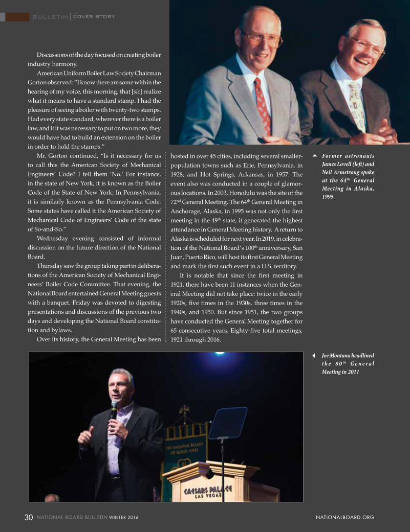
COVER STORY
Discussions of the day focused on creating boiler industry harmony.
American Uniform Boiler Law Society Chairman Gorton observed: “I know there are some within the hearing of my voice, this morning, that [sic] realize what it means to have a standard stamp. I had the pleasure of seeing a boiler with twenty-two stamps. Had every state standard, wherever there is a boiler law, and if it was necessary to put on two more, they would have had to build an extension on the boiler in order to hold the stamps.”
Mr. Gorton continued, “Is it necessary for us to call this the American Society of Mechanical Engineers’ Code? I tell them ‘No.’ For instance, in the state of New York, it is known as the Boiler Code of the State of New York; In Pennsylvania, it is similarly known as the Pennsylvania Code. Some states have called it the American Society of Mechanical Code of Engineers’ Code of the state of So-and-So.”
Wednesday evening consisted of informal discussion on the future direction of the National Board.
Thursday saw the group taking part in delibera-tions of the American Society of Mechanical Engi-neers’ Boiler Code Committee. That evening, the National Board entertained General Meeting guests with a banquet. Friday was devoted to digesting presentations and discussions of the previous two days and developing the National Board constitu-tion and bylaws.
Over its history, the General Meeting has been
hosted in over 45 cities, including several smaller-population towns such as Erie, Pennsylvania, in 1928; and Hot Springs, Arkansas, in 1957. The event also was conducted in a couple of glamor-ous locations. In 2003, Honolulu was the site of the 72nd General Meeting. The 64th General Meeting in Anchorage, Alaska, in 1995 was not only the first meeting in the 49th state, it generated the highest attendance in General Meeting history. A return to Alaska is scheduled for next year. In 2019, in celebra-tion of the National Board’s 100th anniversary, San Juan, Puerto Rico, will host its first General Meeting and mark the first such event in a U.S. territory.
It is notable that since the first meeting in 1921, there have been 11 instances when the Gen-eral Meeting did not take place: twice in the early 1920s, five times in the 1930s, three times in the 1940s, and 1950. But since 1951, the two groups have conducted the General Meeting together for 65 consecutive years. Eighty-five total meetings, 1921 through 2016.
Former astronauts James Lovell (left) and Neil Armstrong spoke at the 64th General Meeting in Alaska, 1995
Joe Montana headlined t h e 8 0 t h G e n e r a l Meeting in 2011
COVER STORY
30 NATIONAL BOARD BULLETIN WINTER 2016 NATIONALBOARD.ORG
BULLETIN

One reason both attendees and guests have been attracted to the General Meeting is the time reserved for socializing. In addition to receptions where all participants can renew old acquaintances, make new friends, and share in the comradery unique to the pressure equipment industry, guests are treated to complimentary tours on Monday afternoon and Tuesday when technical sessions are in progress. On Wednesday, attendees and guests alike are transported to an extraordinary location for a day of special activities including lunch. Past excursions have featured visits to the majestic Portage Glacier near Anchorage; the Kennedy Space Center; the
USS Arizona Memorial with lunch aboard the USS Missouri; and the Texas Motor Speedway.
While much has been said over the years regarding General Meeting social activities, the conference objective has never wavered during its long and distinguished history. That objective, quite simply, was and is to exchange expertise and technical insight with other attendees. Through numerous industry and committee meetings, at-tendees also establish new contacts and avenues of communication that can be utilized all year as opposed to at just one meeting each spring.
Until recently, selection of a city or hotel was based primarily on geography, with locations rotated among quadrants of the United States and various cities in Canada. Lately, however, meeting growth has necessitated an extraordinarily large number of meeting rooms that has greatly limited hotel choices to facilities having a large inventory of meeting space. Although new hotels are being constructed all over North America, those with a large number of meeting rooms remain at a pre-mium, thus prompting returns to some previous hotel locations.
Among the highlights of recent General Meetings has been the Monday Opening Session featuring notable speakers. This distinguished list includes: President Gerald Ford; former astronauts Neil Armstrong, Eugene Cernan, James Lovell, Pete Conrad, and Alan Bean; cultural critic Ralph Nader; former press secretary to President John F. Kennedy, Pierre Salinger; military icon Admiral Hyman G. Rickover; entertainers Charlton Heston, Bob Newhart, and James Caan; former NASA flight director Gene Kranz; and NFL Hall of Fame leg-ends Roger Staubach, Joe Montana, Ray Nitschke, Franco Harris, Don Shula, and Chuck Noll.
Each Opening Session is preceded by an en-ergetic warmup act designed to build audience enthusiasm. In the past, these performances have comprised such groups as the high-stepping and renowned Kilgore Rangerettes; the Band of the Royal Regiment of Canada; Drum Café; and the violins of Spinphony. At the 73rd meeting in 2004, the Opening and General Sessions were conducted on the stage of the Grand Ole Opry in Nashville.
The Monday General Sessions have dealt primarily with pressure equipment topics such
R e t i r e d l o n g t i m e former National Board employee Joan Webster suited up to drive on the Texas Speedway at the 76th General Meeting
Legendary comedian and actor Bob Newhart addressed the 83 rd
General Meeting
31 WINTER 2016 NATIONAL BOARD BULLETIN NATIONALBOARD.ORG
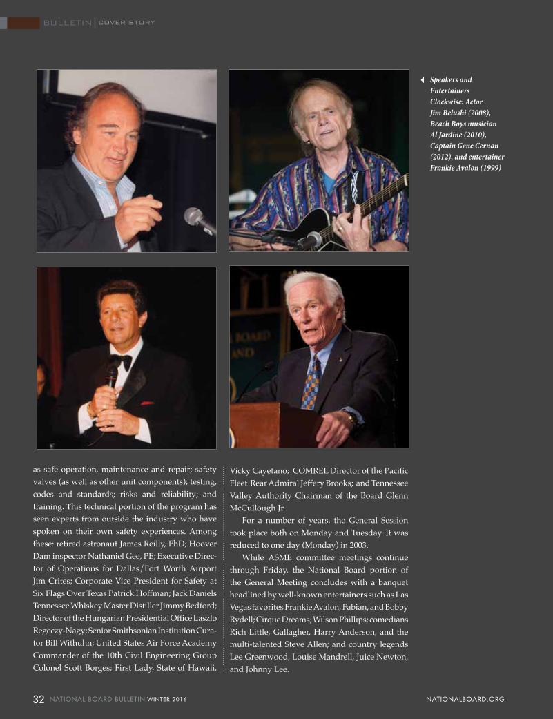
as safe operation, maintenance and repair; safety valves (as well as other unit components); testing, codes and standards; risks and reliability; and training. This technical portion of the program has seen experts from outside the industry who have spoken on their own safety experiences. Among these: retired astronaut James Reilly, PhD; Hoover Dam inspector Nathaniel Gee, PE; Executive Direc-tor of Operations for Dallas/Fort Worth Airport Jim Crites; Corporate Vice President for Safety at Six Flags Over Texas Patrick Hoffman; Jack Daniels Tennessee Whiskey Master Distiller Jimmy Bedford; Director of the Hungarian Presidential Office Laszlo Regeczy-Nagy; Senior Smithsonian Institution Cura-tor Bill Withuhn; United States Air Force Academy Commander of the 10th Civil Engineering Group Colonel Scott Borges; First Lady, State of Hawaii,
Vicky Cayetano; COMREL Director of the Pacific Fleet Rear Admiral Jeffery Brooks; and Tennessee Valley Authority Chairman of the Board Glenn McCullough Jr.
For a number of years, the General Session took place both on Monday and Tuesday. It was reduced to one day (Monday) in 2003.
While ASME committee meetings continue through Friday, the National Board portion of the General Meeting concludes with a banquet headlined by well-known entertainers such as Las Vegas favorites Frankie Avalon, Fabian, and Bobby Rydell; Cirque Dreams; Wilson Phillips; comedians Rich Little, Gallagher, Harry Anderson, and the multi-talented Steve Allen; and country legends Lee Greenwood, Louise Mandrell, Juice Newton, and Johnny Lee.
Speakers and Entertainers Clockwise: Actor Jim Belushi (2008), Beach Boys musician Al Jardine (2010), Captain Gene Cernan (2012), and entertainer Frankie Avalon (1999)
COVER STORY
32 NATIONAL BOARD BULLETIN WINTER 2016 NATIONALBOARD.ORG
BULLETIN
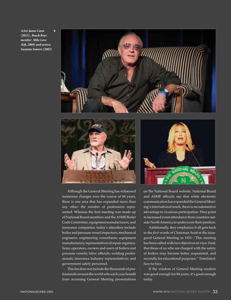
Actor James Caan (2015) , Beach Boys member Mike Love (left, 2009) and actress Suzanne Somers (2002)
Although the General Meeting has witnessed numerous changes over the course of 84 years, there is one area that has expanded more than any other: the number of professions repre-sented. Whereas the first meeting was made up of National Board members and the ASME Boiler Code Committee, equipment manufacturers, and insurance companies; today’s attendees include boiler and pressure vessel inspectors; mechanical engineers; engineering consultants; equipment manufacturers; representatives of repair organiza-tions; operators, owners and users of boilers and pressure vessels; labor officials; welding profes-sionals; insurance industry representatives; and government safety personnel.
This list does not include the thousands of pro-fessionals around the world who each year benefit from accessing General Meeting presentations
on the National Board website. National Board and ASME officials say that while electronic communication has expanded the General Meet-ing’s international reach, there is no substantive advantage to vicarious participation. They point to increased event attendance from countries out-side North America to underscore their position.
Additionally, they emphasize it all gets back to the first words of Chairman Scott at the inau-gural General Meeting in 1921: “This meeting has been called with two objectives in view. First, that those of us who are charged with the safety of boilers may become better acquainted, and secondly for educational purposes.” Translated: face-to-face.
If the wisdom of General Meeting creators was good enough for 84 years, it’s good enough today.
33 WINTER 2016 NATIONAL BOARD BULLETIN NATIONALBOARD.ORG
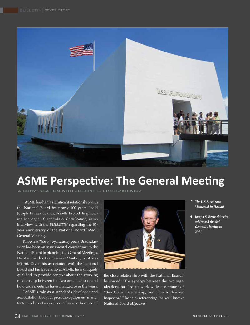
“ASME has had a significant relationship with the National Board for nearly 100 years,” said Joseph Brzuszkiewicz, ASME Project Engineer-ing Manager - Standards & Certification, in an interview with the BULLETIN regarding the 85-year anniversary of the National Board/ASME General Meeting.
Known as “Joe B.” by industry peers, Brzuszkie-wicz has been an instrumental counterpart to the National Board in planning the General Meetings. He attended his first General Meeting in 1979 in Miami. Given his association with the National Board and his leadership at ASME, he is uniquely qualified to provide context about the working relationship between the two organizations, and how code meetings have changed over the years.
“ASME’s role as a standards developer and accreditation body for pressure equipment manu-facturers has always been enhanced because of
the close relationship with the National Board,” he shared. “The synergy between the two orga-nizations has led to worldwide acceptance of, ‘One Code, One Stamp, and One Authorized Inspector,’ ” he said, referencing the well-known National Board objective.
ASME Perspective: The General Meeting A CONVERSATION WITH JOSEPH S. BRZUSZKIEWICZ
The U.S.S. Arizona Memorial in Hawaii
Joseph S. Brzuszkiewicz addressed the 80th General Meeting in 2011
COVER STORY
34 NATIONAL BOARD BULLETIN WINTER 2016 NATIONALBOARD.ORG
BULLETIN
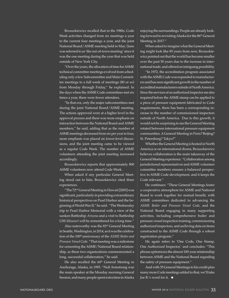
Brzuszkiewicz recalled that in the 1980s, Code Week activities changed from six meetings a year to the current four meetings a year, and the joint National Board/ASME meeting held in May/June was referred to as ‘the out-of-town meeting’ since it was the one meeting during the year that was held outside of New York City.
“Over the years, the allocation of time for ASME technical committee meetings evolved from sched-uling only a few Subcommittee and Main Commit-tee meetings to a full week of meetings (80 or so) from Monday through Friday,” he explained. In the days when the ASME Code committees met six times a year, there were fewer attendees.
“In that era, only the major subcommittees met during the joint National Board/ASME meeting. The actions approved were at a higher level in the approval process and there was more emphasis on interaction between the National Board and ASME members,” he said, adding that as the number of ASME meetings decreased from six per year to four, more emphasis was placed on lower-level discus-sions, and the joint meeting came to be viewed as a regular Code Week. The number of ASME volunteers attending the joint meeting increased accordingly.
Brzuszkiewicz reports that approximately 800 ASME volunteers now attend Code Week.
When asked if any particular General Meet-ing stood out to him, Brzuszkiewicz cited three experiences.
“The 72nd General Meeting in Hawaii [2003] was significant, particularly in providing extraordinary historical perspectives on Pearl Harbor and the be-ginning of World War II,” he said. “The Wednesday trip to Pearl Harbor Memorial with a view of the sunken Battleship Arizona and a visit to Battleship USS Missouri will be remembered for a long time.”
Also noteworthy was the 83rd General Meeting in Seattle, Washington, in 2014, as it was the celebra-tion of the 100th anniversary of the ASME Boiler and Pressure Vessel Code. “That meeting was a milestone for cementing the ASME/National Board relation-ship, as these two organizations commemorated a long, successful collaboration,” he said.
He also recalled the 64th General Meeting in Anchorage, Alaska, in 1995. “Neil Armstrong was the main speaker at the Monday morning General Session, and many people spent extra time in Alaska
enjoying the surroundings. People are already look-ing forward to revisiting Alaska for the 86th General Meeting in 2017.”
When asked to imagine what the General Meet-ing might look like 85 years from now, Brzuszkie-wicz pointed out that the world has become smaller over the past 50 years due to the increase in inter-national trade, and offered an intriguing possibility.
“In 1972, the accreditation program associated with the ASME Code was expanded to manufactur-ers and has seen significant growth in the number of accredited manufacturers outside of North America. Since the services of an authorized inspector are also required before the ASME stamp can be applied to a piece of pressure equipment fabricated to Code requirements, there has been a corresponding in-crease in the number of commissioned inspectors outside of North America. Due to this growth, it would not be surprising to see the General Meeting rotated between international pressure equipment communities. A General Meeting in Paris? Beijing? St. Petersburg? Tokyo?”
Whether the General Meeting is hosted in North America or on international shores, Brzuszkiewicz believes collaboration is the main takeaway of the General Meeting experience. “Collaboration among jurisdictional representatives and ASME volunteer committee members ensures a balanced perspec-tive in ASME Code development, and it keeps the Code relevant.”
He continues: “These General Meetings foster a cooperative atmosphere for ASME and National Board to work together for mutual benefit, with ASME committees dedicated to advancing the ASME Boiler and Pressure Vessel Code, and the National Board engaging in many supporting activities, including comprehensive boiler and pressure vessel inspection training, commissioning authorized inspectors, and archiving data on items constructed to the ASME Code through a robust registration program.”
He again refers to ‘One Code, One Stamp, One Authorized Inspector,’ and concludes: “This phrase epitomizes the almost 100-year relationship between ASME and the National Board regarding the safety of pressure equipment.”
And with 35 General Meetings to his credit plus many more Code meetings added to that, we’ll take Joe B.’s word for it.
35 WINTER 2016 NATIONAL BOARD BULLETIN NATIONALBOARD.ORG
Can I Use an ASME Section VIII Steam Pressure Relief Valve on an ASME Section I Boiler?BY THOMAS P. BEIRNE, P.E., TECHNICAL MANAGER, PRESSURE RELIEF DEPARTMENT
This question has been posed to the National Board Pressure Relief Department several times in the past few years. Several valve types on the market meet both Section I and Section VIII requirements and therefore are dual certified, meaning that either
the V or UV Designator may be applied to a certain valve type depending on the appli-cation. Because there are many valve types on the market that have dual certification in which they could be stamped with either a V or a UV Designator, it becomes even harder for people to understand why an identical ASME Boiler and Pressure Vessel Code Section
VIII version of the same ASME Boiler and Pressure Vessel Code Section I valve cannot be used in a Section I application. This article will detail several differences between Section VIII and Section I. In doing so, it will show reasons why only a Section I pressure relief valve (PRV) shall be used in Section I applications.
Capacity
Capacity is the first and probably most important reason that a Section VIII valve cannot be used in Section I applications. The difference in capacity comes from the pressure at which the rated capacity is calculated. This pressure is defined as the rated overpressure (P).
For Section I, the rated overpressure (P) from which the capacity is calculated is as follows:
Set Pressure x 1.03 + 14.7 psia.For Section VIII, the rated overpressure (P) from which the capacity is calculated is as follows:
Set Pressure x 1.10 + 14.7 psia.Note: Overpressures vary for low pressures. Consult Code.
To better illustrate the difference in capacity between the two code sections, let us run through an example calculation. In our example we will assume we have two identical valves. One is marked with a V Designator and one is marked with a UV Designator. Both valves are set at 100 psi and have a flow area (A) of 0.785 sq. in. and a coefficient of discharge (K) of 0.877.
The formula used in both sections to calculate rated capacity is as follows: Capacity=51.5xAxPxK. The term P in the equa-tion is the rated overpressure expressed in absolute terms. For Section I, the rated overpressure (P) is the set pressure times 1.03 + 14.7. For Section VIII, the rated overpressure (P) is the set pressure times 1.10 +14.7.
The Section I capacity calculation is as follows: 51.5x0.785x(100x1.03+14.7)x0.877= 4,173 lbs./hr.
The Section VIII capacity calculation is as follows: 51.5x0.785x(100x1.10+14.7)x0.877= 4,421 lbs./hr.
Now, let us assume we have a Section I boiler with a steam-ing capacity of 4,300 lbs./hr. Installation of a Section VIII valve, even though its stamped capacity exceeds 4,300 lbs./hr., in a Section I application would be capacity certified for 4,173 lbs./hr. Therefore, in the Section I installation, it would not have enough rated capacity.
Set Pressure Tolerance
For both Sections I and VIII the set pressure tolerance is the same for pressures up to and including 300 psi. Above 300 psi is where the set pressure tolerance differs between the two code sections. For Section VIII, the set pressure tolerance remains at +/- 3%. For Section I, it is +/- 10 psi for set pressures between 300 and 1,000 psi and +/- 1% for set pressures greater than 1,000 psi.
For a boiler installation where the set pressure is greater than 300 psi, the set pressure tolerance for a Section I pressure relief valve becomes more stringent than for Section VIII. The difference in set pressure tolerance becomes magnified as pressure increases. For example, at 1,000 psi, the maximum set pressure tolerance would be 1,010 psi for Section I and 1,030 psi for Section VIII. In a Section I installation, using a Section VIII safety valve, the set pressure would be out of tolerance.
Blowdown
Section I specifies a minimum blowdown of 2 psi or 2%, whichever is greater. This minimum requirement ensures smooth operation without chatter. Section VIII does not specify a minimum. If a Section VIII valve with adjustable blowdown is improperly set due to the lack of blowdown requirements, the valve could chatter and not relieve the capacity it was designed for.
36 NATIONAL BOARD BULLETIN WINTER 2016 NATIONALBOARD.ORG
BULLETIN INSPECTOR'S INSIGHT

Materials
If the valve is certified only for Section VIII and not dual certified, this could be a limiting factor as well. There are numerous materials that are permitted for use in Section VIII construction that are not permitted in Section I.
Nameplate Marking Requirements
Section VIII, Division 1, provides very clear wording on the allowance of Section I valves in Section VIII service. Section VIII under UG-129(b) states: “Safety and safety relief valves certified for a steam discharging capacity under the provisions of Section I and bearing the Certification Mark with the V Designator for safety valves may be used on pressure vessels. The rated capacity in terms of other fluids shall be determined by the method of conversion given in Mandatory Appendix 11.” This very clearly allows the use of a valve bearing the V Designator for use on a Section VIII, Division 1, pressure vessel.
Unfortunately, Section I is not quite as clear in disallowing valves constructed under the rules of other code sections. No-where in Section I does it state that “only a valve bearing the V Designator shall be used for Section I applications.” Instead, the only direction is given by PG-110, “Stamping of Boiler Pressure Relief Valves.” The last sentence of PG-110 states, “The marking shall include the following:”.
Reading on from there, to get to the V Designator, we must continue to paragraph PG-110(g) which states, “Certification Mark as shown in Figure PG-105.1 with a V Designator placed under
the Certification Mark. A marking method other than the stamp is-sued by the Society may be used, provided that it is acceptable to the ASME designated organization.” The marking method is not to be confused with the Designator or Certification Mark itself, but only the method used in applying them (such as laser or mechanical etching).
NBIC Question
If I have a Section VIII valve with a UV Designator that is dual certified for Section I, can I use it in a Section I application if I repair it under the VR program, recalculate the capacity, and reset the valve to meet Section I set pressure and blowdown requirements?
The answer is no. There are no provisions in either ASME or the National Board Inspection Code for altering the Designator or the old Code Symbol stamp, and PG-110(g) states that it shall be marked with the V Designator. If the valve is marked with a UV, it cannot be used for a Section I application.
Summary
Overall, Section I is more stringent than Section VIII in terms of valve performance (set pressure, blowdown, and capacity) and is more limiting in the materials that are permitted for use in construction. Additionally, the nameplate marking require-ments state that a Section I valve shall be marked with the V Designator. Now you can answer the question, “Can I use an ASME Section VIII steam pressure relief valve on a Section I power boiler?”
Example of ASME Certification Mark with "V" Designator indicating Section I
Example of ASME Certification Mark with "UV" Designator indicating Section VIII
37 WINTER 2016 NATIONAL BOARD BULLETIN NATIONALBOARD.ORG

childhood” and religious upbringing that set the tone for his adolescence and transi-tion to adulthood. (More on the Mark and Kevin thing later.)
“My dad was a welder and my mom worked as a clerk in a hospital,” he dis-closes with a grin. “They both were good Christian people. Good Christian people,” he repeats for emphasis. “I grew up with three older sisters who were pretty protec-tive of their younger brother.”
Tipton is a small agricultural com-munity and just a short ride to Purdue University. “Spelled differently. And home of the Boilermakers,” Kevin notes ironically.
The Oregon official attended a small high school in Tipton where he partici-pated in track, football, and wrestling. It was at an indoor track meet at Purdue University that Kevin established a high school record for the 60-yard high hurdles.
“While in high school I thought about becoming a bricklayer. But getting an ap-prenticeship was next to impossible,” he observes. With his dad being a welder, Kevin decided to pursue welding in his high school shop class.
Kevin’s experience in shop class re-vealed two things: that he liked welding and he was good at it.
“A friend of my dad told me that if I wanted it, I could have a welding job within a week of my high school gradu-ation,” he explains. And so, seven days after receiving his diploma in 1974, Kevin was at work welding tanks for fire trucks.
“After three years,” he recalls, “I was bored. These were 1,000 to 1,500-gallon tanks. Every day, I felt as though I was working inside a big can. I knew there had to be more than MIG welding!”
In 1977, the Oregon National Board member quit his job and set out for Harts-ville, Tennessee, and what he hoped would be construction work on the world’s largest nuclear power plant. “I was de-termined to get a welding job,” he smiles, “but it didn’t work out.” Which may have
Mark K. Perdue Oregon Chief Boiler Inspector
Kevin Perdue reveals an impish grin when asked to describe his life.
“You know,” he casually explains, “it just seems that things have always seemed to fall into place for me. And I mean that in a good sense. I think there’s a word for that.”
Indeed. The word is serendipity and the Oregon chief inspector’s life’s journey that began in Indiana has been a road of quirky occurrences paved with good fortune.
Born Mark Perdue in Tipton, Indiana, Kevin credits his parents with a “great
38 NATIONAL BOARD BULLETIN WINTER 2016 NATIONALBOARD.ORG
BULLETIN PROFILE IN SAFETY
BULLETIN photo by Kelley J. James Photography
been fortuitous. The troubled project was cancelled in 1983.
“A friend who bragged of all kinds of welding work in Louisiana encouraged me to travel south. While there were quite a few open welding positions in Louisiana, the wage scale didn’t even compare to what I was making at my first job welding tanks,” he laments.
The discouraged Tipton native headed to Goshen, Indiana, where he lived with his sister while searching for work. Discouragement turned to encouragement when he landed a job at a company that manufactured large concrete silos. Shovel-ing concrete, he quickly discovered, was back-breaking work. Two days later, the Oregon official was again unemployed. By choice.
“I was probably at the lowest point in my life,” he admits without hesitation. “I’m destitute without any job prospects.”
Kevin traveled to Hoopston, Illinois, where he visited two of his sisters, who vowed to help him find gainful employ-ment. “They were both heavily involved in the church,” he remembers. Despite some reservations, Kevin decided that some divine intervention couldn’t make his predicament any worse.
“While working as a tool setter at my first job since coming to Illinois, I met this beautiful lady Ricki,” Kevin beams. Or at least he thought he met a beautiful lady named Ricki. “On our first date, I kept referring to her as Ricki. She finally told me her real name was Vicki. As it turned out, she didn’t mind being called Ricki because she actually liked the name better.
“In 1978, I went to work for FMC in Hoopston, the same company I joined following high school graduation, albeit in a different city.”
Kevin discovered corporate FMC would honor his earlier three-year em-ployment seniority welding fire engine tanks. “I was now in a different plant,” he smiles, “and it involved food process-ing welding.”
With a new job, Kevin proposed to Vicki and launched a new chapter in his life. It wasn’t too long before the Perdues welcomed a baby son in 1979, followed several years later by a daughter and another son.
The new position was professionally enlightening for several different reasons. “For the first time in my life I became familiar with ASME welding standards. Because it was an ASME shop, I was introduced to all types of welding.” And suddenly the welding profession knew no bounds.
“Passing my certification to weld on cookers was only the beginning,” he laughs. “I followed with certifications in GTAW, GMAW, SMAW, and SAW.”
The Indiana native remained with FMC until 1995 when the company began downsizing through outsourcing. Conse-quently, he was hired by Parker Hannifin as a nuclear class welder.
“In 1995, my dad was having some health issues so I left Parker Hannifin after just a few months. We packed up the family to be closer to my parents in Cookeville, Tennessee. Looking for a job in the area, I happened across a small welding company that had just enough work to keep the doors open.”
Kevin approached the firm with a proposition: “Hire me as a welder and salesperson. I have the contacts to bring in welding work and expand your busi-ness!” And they did.
The challenge, from Kevin’s view-point, involved a company employing older welders set in their ways. “As the company grew, we hired and I trained. Though I was able to bring in work to bid on, the company started getting busy with military contracts, and my abilities were useful in securing those contracts and certifying new welders in procedures I developed and qualified.”
While the company tripled its busi-ness during his 10-year tenure, Kevin became involved with ASME Section IX,
as well as Sections VIII and V. For two years he flirted with the company’s authorized inspection agency, who wanted him as an inspector – if he could pass the National Board Commission Exam.
Thrice taking the exam, he succeeded on his last attempt and quickly discovered that commissioned inspectors were in demand. Unbeknownst to him, a plan was afoot to get Kevin and Vicki to Oregon.
“Oregon was where our grandchildren lived,” he says. “So that she could be closer to them, Vicki was surreptitiously looking for jobs for me in Oregon. I wanted to be a shop inspector but my wife convinced me to submit an application to the state of Oregon for an inspector position. When the application was received, I had two telephone interviews before I received an in-person interview.”
In 2006, Kevin headed to Salem, Or-egon, and a new job as state boiler inspector. Upon his arrival, it was discovered that the building codes division was awash in staff members named Mark, Kevin’s real first name. “To avoid getting lost in the crowd,” he chuckles, “I began using Kevin, my middle name, to avoid confusion.”
If there was anything that did confuse Kevin upon being hired, it was, “I was a boiler inspector who knew nothing about boilers!” It’s a paradox the multi-certified welder holds true even today.
In 2013, seven years after assuming his post as inspector, Kevin became Or-egon chief inspector and a member of the National Board.
“It’s amazing,” Kevin shakes his head, “although there have been some bumps and bruises along the way, I believe those down-turns were essential in order to appreciate the successes.”
Another thing Kevin believes to this day is that his return to the church in the mid-1970s was responsible for all the good things that “seemed to fall into place for me.”
Inclined to label certain events in his life, he observes with a wink: “There’s a word for that: reborn.”
39 WINTER 2016 NATIONAL BOARD BULLETIN NATIONALBOARD.ORG
New Year, New CalendarThe 2016 Training Schedule Has Much to OfferBY KIMBERLY MILLER, MANAGER OF TRAINING
The National Board training depart-ment is gearing up for another busy year in 2016. Currently there
are 25 classes scheduled for a total of 38 weeks of training, most being conducted on our campus in Columbus, Ohio.
Of course, commission training is a high priority, with 24 of the 38 weeks dedicated to training students to become inservice and new construction commis-sioned inspectors.
The New Construction Commission and Authorized Inspector Course (A) is on the calendar seven times in 2016: February, April, June, July/August, September, October, and De-cember. Students spend nine days between the classroom and inspection room learning the discipline of becoming an authorized inspector; the 85-question, two-part exami-nation is then administered on day 10. As always, this course is in high demand so enrolling early is encouraged.
The Inservice Commission Course (IC) has five dates set for 2016: January, March, May, August, and November. Students attending this training spend nine days learning ASME and NBIC code requirements in the classroom, which is complemented with time in our hands-on inspection room. Just like in the New Construction course, the tenth day is assessment day, when students may sit for the final examination.
An important note about the two commission courses: While originally designed for the student wishing to obtain a National Board Commission, this training also meets the requirements of individuals seeking the Pressure Equipment Inspector (PEI) certification. For more information on the PEI program, please visit Commissions & Certifications/Pressure Equipment Inspectors at nationalboard.org.
Also on the calendar for 2016 is a menu of nuclear train-ing which includes two Authorized Nuclear Inspector Course (N) dates, one Authorized Nuclear Inservice Inspector Course (I), and one Authorized Nuclear Inspector Supervisor Course
TRAINING MATTERSBULLETIN
(NS). The first of the nuclear courses to be held will be the N Course, with a class already completed in January and a second scheduled for July. The NS and I courses will fol-low, with dates in February and September, respectively. Currently there is no Authorized Nuclear Inspector (Concrete) (C) endorsement course scheduled in 2016, but it will return to the calendar in 2017.
The remaining training calendar consists of two Autho-rized Inspector Supervisor (B) class dates: one in April and the second in October; two Pressure Relief Valve Repair (VR) seminars in Columbus (March and June); and two Boiler and Pressure Vessel Repair (RO) seminars in Columbus (March and June). Both the VR and RO repair seminars will be con-ducted off-site in 2016, with the VR returning to Houston,
Texas; and the RO returning to Portland, Oregon. The ex-act dates will be released on the National Board website in early spring.
For students unable to travel to our classroom train-ing but still wanting to take some type of National Board training, you’re in luck. There are more online training
courses being offered today than ever before in the history of National Board training. With 26 different titles in our menu of online training, students have a variety of courses to choose from. In addition, the courses originally qualified as continuing education for 2013 and 2014 renewals have been updated and will be re-released in the first quarter of 2016. Development of new online training is also well underway for at least three new courses this year: Certified Individual for Bioprocessing Equipment; a new mathematics course; and training covering installation of pressure equipment.
Whether in the classroom or online, there is National Board training to fit most everyone’s needs in 2016!
Author’s Note: Did you know examination questions may be submitted to the National Board for use in any commission or endorsement exam? To do so visit nationalboard.org, “Training/Submit an Exam Question.”
40 NATIONAL BOARD BULLETIN WINTER 2016 NATIONALBOARD.ORG
There are more online training courses being offered today than ever before in the history of National Board training. With 26 different titles in our menu of
online training, students have a variety of courses to choose from.
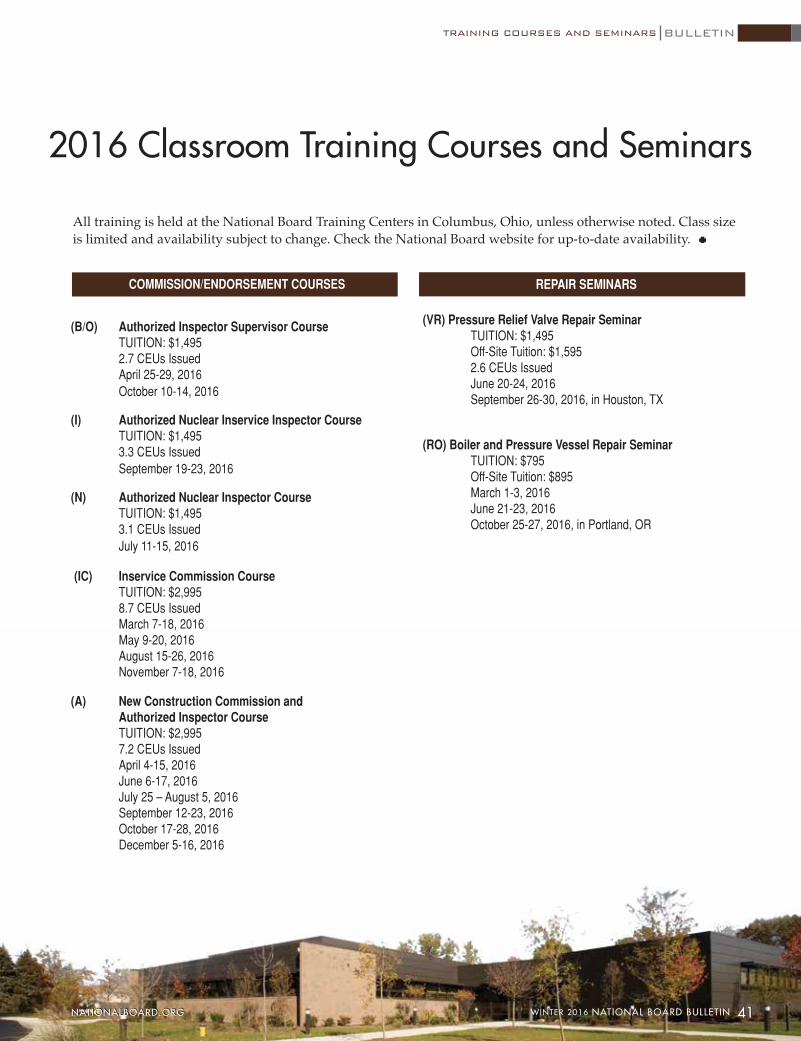
REPAIR SEMINARSCOMMISSION/ENDORSEMENT COURSES
2016 Classroom Training Courses and Seminars
(B/O) Authorized Inspector Supervisor Course TUITION: $1,495 2.7 CEUs Issued April 25-29, 2016 October 10-14, 2016
(I) Authorized Nuclear Inservice Inspector Course TUITION: $1,495 3.3 CEUs Issued September 19-23, 2016
(N) Authorized Nuclear Inspector Course TUITION: $1,495 3.1 CEUs Issued July 11-15, 2016
(IC) Inservice Commission Course TUITION: $2,995 8.7 CEUs Issued March 7-18, 2016 May 9-20, 2016 August 15-26, 2016 November 7-18, 2016
(A) New Construction Commission and Authorized Inspector Course TUITION: $2,995 7.2 CEUs Issued April 4-15, 2016 June 6-17, 2016 July 25 – August 5, 2016 September 12-23, 2016 October 17-28, 2016 December 5-16, 2016
(VR) Pressure Relief Valve Repair Seminar TUITION: $1,495 Off-Site Tuition: $1,595 2.6 CEUs Issued June 20-24, 2016 September 26-30, 2016, in Houston, TX
(RO) Boiler and Pressure Vessel Repair Seminar TUITION: $795 Off-Site Tuition: $895 March 1-3, 2016 June 21-23, 2016 October 25-27, 2016, in Portland, OR
All training is held at the National Board Training Centers in Columbus, Ohio, unless otherwise noted. Class size is limited and availability subject to change. Check the National Board website for up-to-date availability.
BULLETIN
41WINTER 2016 NATIONAL BOARD BULLETIN NATIONALBOARD.ORG 41 WINTER 2016 NATIONAL BOARD BULLETIN NATIONALBOARD.ORG
TRAINING COURSES AND SEMINARS

UPDATES & TRANSITIONS
42 NATIONAL BOARD BULLETIN WINTER 2016 NATIONALBOARD.ORG
BULLETIN
Member Retirement Mississippi Chief Kenneth Watson retired on October 16, 2015. Mr. Watson served in the US
Navy and was assigned duty on the USS Flint (AE-32). His first civilian job was with Arkansas Power & Light. In 1980 he joined the state of Arkansas as a deputy boiler inspector. During his tenure with Arkansas, he held varying positions, from deputy to chief inspector. He retired from Arkansas in 2003. In 2005, he joined the state of Mississippi as a deputy inspector, and was ap-pointed chief in 2007.
In RemembranceMichael Barber, former National Board member representing Detroit, Michigan, passed away
October 29, 2015. Mr. Barber served in the US Navy from 1971 to 1975, assigned to the USS Kitty Hawk. He graduated from Wayne State University with a bachelor’s degree in mechanical engi-neering technology. His work history included employment with the City of Detroit; owner of Mail Plus from 1992 to 1997; loss control manager for Zurich America Insurance Company for 15 years, and loss control representative for Factory Mutual. He also served as president of the Michigan Boiler Inspectors Association from 1988 to 1992.
Jim Keenan, former National Board independent consultant and training employee, died on October 27, 2015. He was 73 years old. Mr. Keenan served in the US Navy and was a veteran of the Vietnam War. He was a boiler technician and then served as a utilitiesman in the US Naval Construction Forces (Seabees), and attained the rank of 1st class. He was also a member of the Civil Engineer Corps/Seabee Historical Foundation.
Molvie Awarded J. Hall Taylor MedalNational Board Advisory Committee member (representing boiler manufacturers) Peter A.
Molvie, P.E., was honored by ASME with the J. Hall Taylor Medal for distinguished service or eminent achievement in the codes and standards area pertaining to the broad fields of piping and pressure vessels. Specifically, ASME recognized Molvie’s “distinguished leadership and professionalism in the advancement and recognition of ASME codes and standards for pressure equipment, and for significant contributions to the development and standardization of power and heating boiler equipment design and construction” (Mechanical Engineering, November 2015). Mr. Molvie is manager of codes and standards at Cleaver-Brooks in Milwaukee.
Nicholas Surtees
Nicholas Surtees
Kenneth Watson
Michael Barber
Jim Keenan
Peter Molvie

New Members Sam Chapman now represents Tennessee. Mr. Chapman served in the US Navy as a boiler
technician from 1979 until 1999. During his civilian career he was employed with the state of Tennessee as a deputy boiler inspector (2002 to 2009) and assistant chief boiler inspector (2009 to 2015). He assumed the role of chief inspector in August 2015.
Kenneth Scott Lane represents Alaska. Mr. Lane served in the US Air Force from 1982 to 1992 as a heating, air-conditioning, and refrigeration technician. He worked for CNA Insurance Company between 1996 and 1998 as a boiler and machinery inspector. He served in the Air National Guard between 1994 and 2000 as a heating and air-conditioning technician, and then as a nondestructive inspection technician from 2000 to 2006. He was also employed with the state of Alaska as a boiler and pressure vessel inspector from 1999 to 2006. In 2007 he went to work for the state of North Carolina as a deputy boiler inspector until returning to Alaska as a boiler and pressure vessel inspector in 2011.
Membership NewsThe National Board held its annual October Technical Members’ Meetings the week of
October 5, 2015. A new member was voted in and three National Board members were awarded for years of service during the week’s events.
Membership for Kenneth Scott Lane (Alaska) was acted on by the Board of Trustees on Monday, October 5. At the Members’ Meeting on Tuesday, October 6, the following members were recognized for years of service with the National Board: William McGivney, City of New York, NY: 10 years; Dennis Hannon, State of Arkansas: five years; and Cirilo Reyes, City of Los Angeles, CA: five years.
43 WINTER 2016 NATIONAL BOARD BULLETIN NATIONALBOARD.ORG
Kenneth Scott Lane
Sam Chapman

FEATURE
Subsequently, the number of Nation-al Board and ASME stamp holders has also risen: In December of 2007
there were 13 National Board and ASME stamp holders in the state. Since 2007, that number has climbed to 38 stamp holders.
Austin says a combination of many factors has brought about the successful results in his jurisdiction. “These results, especially the increase of R stamps in the state, naturally occurred from enforcing state rules,” he says. “As we began doing that, the number of shops holding stamps went up in our state because enforcements meant more stamp holders were needed.”
His first priority back in 2007 was to build a strong team of experienced inspec-tors and keep them. “State inspectors were coming and going through a revolving door because the pay scale was not com-petitive,” he explains.
Austin approached his director and explained to him, “If we want to maintain professional levels in our department and put a stop to the revolving door, we need to increase pay.” And they did.
“We were able to meet the expectations of the candidates and increase pay to match their experience. I had a tremendous amount of support from my supervisor in building my team,” he says.
Other factors Austin attributes to the program’s growth were a policy change regarding special inspectors and updating the state rules regarding inspectors. Austin mandated that all Arizona commissions for special inspectors be renewed yearly. This allowed him to update contacts and clean up the Division’s database. In
Arizona Statistics Show Notable Growth
Since Randall Austin became chief boiler inspector for the Arizona Division of Occupational Safety and Health (ADOSH) Boiler Safety Section in 2007, the program has experienced notable growth. The number of inspections performed by special inspectors and state inspectors has in-creased 110 percent overall.
addition, all new special inspectors must meet with him in person before they are issued an Arizona commission. During the meeting, Austin outlines the state’s expecta-tions and provides a packet of mandatory reading materials.
Next, Austin replaced outdated state rules and now requires current editions of ASME and National Board codes. “The ASME Boiler and Pressure Vessel Code and the National Board Inspection Code (NBIC) are living documents and are always improv-ing, and our state codes needed to reflect the updates. Arizona ADOSH is big on safety, so everything I’ve asked for they’ve given me,” Austin says, which included a set of current code books for each of his inspectors, as well as test equipment, such as flammable gas and carbon monoxide detectors.
Reaching out to stakeholders also con-tributed to the state’s success. Before imple-menting many of his changes, Austin held meetings with local and state contractors, insurance companies, special inspectors, and others, and showed them how state rules were not updated to current codes. “I explained that changes were coming, and we slowly implemented change.”
Austin’s measured changes have been a formula of success for the Arizona Boiler Safety Section. Reflecting on the progress of his jurisdiction, he admits with a smile, “I didn’t anticipate the growth when I reviewed the numbers.” And while the in-crease in inspections has leveled off, Austin says the number of R stamp holders hasn’t peaked yet. He expects it will continue to grow.
44 NATIONAL BOARD BULLETIN WINTER 2016 NATIONALBOARD.ORG
BULLETIN

WANT TO TAKE A RUN (or WALK)?