waiver for a spiral welded pipe for foundations
TRANSCRIPT

SECTION XX XX XX.XX
SPIRAL WELDED PIPE PILE
January 2010
SCOPE: The Contractor shall provide all labor and materials necessary for the purchasing, delivering, unloading, storing, handling and driving of the spiral welded pipe (SWP) piles as specified herein. Piles shall be supplied full length or in lengths approved by the Contracting Officer provided splices are approved in accordance with paragraph 3.2.3.11 contained herein.
PART 1 GENERAL 1.1 RELATED WORK SPECIFIED ELSEWHERE 1.2 MEASUREMENT AND PAYMENT 1.2.1 Measurement 1.2.2 Payment 1.2.2.1 Driven Piles 1.2.2.2 Pulled Piles 1.2.2.2.1 Inspection 1.2.2.2.2 Damaged Piles 1.2.2.2.3 Misaligned or Misplaced Piles 1.3 REFERENCES 1.4 SUBSURFACE SOIL DATA 1.5 SUBMITTALS 1.6 QUALITY CONTROL 1.7 DELIVERY, STORAGE AND HANDLING 1.7.1 Delivery and Storage 1.7.2 Handling PART 2 PRODUCTS 2.1 MATERIALS 2.1.1 Spiral Welded Pipe 2.1.1.1 Chemical Composition 2.1.1.2 Dimensional Tolerances 2.1.2 Weld Material 2.2 SHOP TESTING
- 1 -

2.3 REPAIRS PART 3 EXECUTION 3.1 INSTALLATION PART I 3.1.1 Pile Driving Equipment 3.1.1.1 Pile Driving Hammers 3.1.1.2 Pile Driving Leads (or Templates) 3.1.1.3 Driving Helmets 3.1.1.4 Cap Blocks (Hammer Cushion) 3.1.1.5 Pile Extractors 3.1.2 Pile Follower 3.2 INSTALLATION PART II 3.2.1 Lengths of Permanent Piles 3.2.2 Pile Placement and Tolerances 3.2.3 Pile Driving 3.2.3.1 Driving Records 3.2.3.2 Penetration Criteria 3.2.3.3 Driving 3.2.3.4 Heaved and Laterally Displaced Piles 3.2.3.5 Pulled Piles (Damaged and Misplaced Piles) 3.2.3.6 Jetting 3.2.3.7 Preboring 3.2.3.8 Void Backfill 3.2.3.9 Cutting of Piles 3.2.3.10 Welding 3.2.3.11 Splicing 3.3 STRUCTURAL AND WELDING TESTS 3.4 TESTING OF MECHANICAL PROPERTIES 3.4.1 Tensile Test 3.4.1.1 Tensile Testing Specimens 3.4.1.2 Tensile Testing Frequency 3.4.1.3 Longitudinal Tensile Tests 3.4.1.4 Transverse tensile Tests 3.4.1.5 Weld Tensile (Reduced Section Tension) Tests 3.4.2 Flattening Tests 3.4.3 Guided-Bend Tests APPENDIX A Dimensional Tolerances Supplemental Sketches APPENDIX B Engineering Notes
- 2 -
APPENDIX C Driving Record Form PART 1 GENERAL 1.1 RELATED WORK SPECIFIED ELSEWHERE (1) Pile Load Tests: See Section 31 62 14.00 12 of the Contract Specifications.
(2) Dynamic Pile Testing: See section 31 62 14.01 22 of the Contract Specifications. (3) Corrosion Protection: See ‘Painting of Hydraulic Structures’, Section 09 97 02 of the Contract Specifications.
1.2 MEASUREMENT AND PAYMENT 1.2.1 MEASUREMENT
SWP piles will be measured for payment on the basis of lengths along the axis of the pile in place. Pile lengths will be measured to the nearest (1/10 foot). The portion of any pile driven below the tip elevation as shown on the drawings, will not be measured for payment unless over-driving is directed by the Contracting Officer. Piles pulled for inspection shall be measured for payment on the basis of lengths along the axis of the pile pulled. Redriving of piles will be measured in accordance with the provisions stated herein. Piles driven with a vibratory hammer will be measured for payment on the basis of pile length determined from the pile test program for piles driven with an impact hammer, see paragraph 3.1.1.1.
1.2.2 PAYMENT 1.2.2.1 Driven Piles
Payment for the measured length of SWP piles will be made at the applicable contract unit price per linear foot for each diameter and wall thickness of SWP piles acceptably driven. Price and payment includes all items incidental to furnishing and driving SWP piles, including field spices, as specified herein. No additional payment will be made for use of an impact hammer on piles which have refused with a vibratory hammer, see paragraph 3.2.3.3.e.
1.2.2.2 Pulled Piles
1.2.2.2.1 Inspection
Each SWP pile pulled at the direction of the Contracting Officer for inspection, and found to be in good condition, will be paid for at the original driven position plus 50 percent of the contract unit price for the length pulled which shall constitute payment for pulling. Payment for a pulled pile shall include backfilling the pile hole if required. Backfilling of the hole shall be as directed by the Contracting Officer. Undamaged pulled piles when redriven acceptably, will be paid for at 50 percent of the contract
- 3 -
unit price for furnishing and driving the measured length of piles redriven, which price and payment shall constitute payment for redriving only. Pulled piles, which are damaged through no fault of the contractor, shall be replaced by a new pile, which will be paid for at the contract unit price for the length of pile acceptably driven.
1.2.2.2.2 Damaged Piles
When a pile is pulled for inspection and found to be damaged due to contractor negligence, no payment will be made for originally furnishing and driving such pile or for the operation of pulling the pile. The damaged pile shall be replaced by a new pile which will be paid for at the contract unit price for the length acceptably driven.
1.2.2.2.3 Misaligned or Misplaced Piles
When a pile is driven, but not acceptably placed or driven out of alignment and pulled at the direction of the Contracting Officer, no payment will be made for either originally furnishing and driving such pile or for the operation of pulling. If the pile is undamaged and it is acceptably redriven at the direction of the Contracting Officer, it will then be paid for at the contract unit price.
1.3 REFERENCES The publications listed below form a part of this specification to the extent referenced. The publications are referred to within the text by the basic designation only.
AMERICAN WELDING SOCIETY (AWS) AWS D1.1 (2008) Structural Welding Code – Steel
ASTM INTERNATIONAL (ASTM) ASTM A 139 (2004) Standard Specification for Electric-Fusion (Arc) – Welded Steel Pipe (NPS 4 and Over) ASTM A370 (2009) Standard Test Methods and Definitions for Mechanical Testing of Steel Products ASTM A 1018 (2008) Steel, Sheet and Strip, Heavy-Thickness Coils, Hot
Rolled, Carbon, Commercial, Drawing, Structural High- Strength, Low Alloy, High Strength Low Alloy with Improved Formability, and Ultra High Strength
AMERICAN PETROLEUM INSTITUTE (API)
API 5L (2009) Specification for Line Pipe
- 4 -

AMERICAN SOCIETY FOR NONDESTRUCTIVE TESTING ASNT CP 189 (2006) Qualification and Certification of Nondestructive Testing Personnel 1.4 SUBSURFACE SOIL DATA Subsurface soil data logs are shown on the drawings. The subsurface reports are available for examination. The subsurface reports are to be used for information only and not as a warranty of the subsurface conditions. The Contractor must recognize that the reports were not prepared for the purposes of bid development. The Contractor may need to conduct additional subsurface studies and investigations to obtain the specific type(s) of information needed or preferred. 1.5 SUBMITTALS Government approval is required for submittals with a “G” designation; submittals not having a “G” designation are for information only. When used, a designation following the “G” designation identifies the office that will review the submittal for the Government. For example, ‘DO’ indicates the District Office. Submit the following in accordance with Section 01 33 00 ‘Submittal Procedures’ of the Contract Specifications. General. The Contractor shall submit descriptions of the proposed pile driving equipment, delivery, storage and handling methods, placement plans, pile removal plans, driving records, quality control records, and other submittals to the Contracting Officer for approval as required. SD-01 Shop Drawings Installation G, DO
Drawings shall be submitted demonstrating compliance of the driving equipment and the SWP piles with the Contract documents. Shop drawings for piles shall provide details and dimensions of all shop and field fabrications. The Contractor shall provide splice details and location. The required non-destructive testing (NDT) of welds shall be shown on the drawings. Delivery, Storage, and Handling G, DO Plans for the proposed methods of delivery, storage, and handling of piles shall comply with the requirements of paragraph ‘Delivery, Storage and Handling’ and shall be submitted for review and approval at least 30 days prior to delivery of piles to the job site.
- 5 -
Placement G, DO Placement plans shall show the proposed methods for controlling location and alignment of piles as required in paragraph ‘Pile Placement and Tolerances’ and shall be submitted for review and approval at least 30 days prior to delivery of piles to the job site.
SD-02 Product Data Spiral Welded Pipe (SWP) Piles G, DO
A complete and accurate record of each driven pile shall be submitted daily. Indicate in the record the pile location (as driven), driven length, embedded length, final elevations of tip and top, pile weight, butt and tip diameter, number of splices and locations, blows required for each foot of penetration throughout the entire length of the pile and for the final 12 inches of penetration and the total driving time. Also include in the record the type and size of the hammer used, the rate of operation, and the type and dimensions of driving helmet and cap block (hammer cushion) used. Record any unusual conditions encountered during pile installation and immediately report these conditions to the Contracting Officer. Record any interruptions or delays during driving, and any other pertinent information. Equipment G, DO Complete descriptions of pile driving equipment, including hammers, power packs, driving helmets, cap block (hammer cushion), leads, extractors and other appurtenances shall comply with the requirements of paragraph ‘Pile Driving Equipment’ and shall be submitted for approval at least 30 days prior to commencement of work. The Contractor shall submit his wave equation analysis for each proposed hammer. In addition, the following information shall be submitted for each proposed hammer ;
(1) Make and model. (2) Ram weight (pounds). (3) Anvil weight (pounds). (4) Weight of the moving parts of the hammer (pounds). (5) Rated stroke (inches). (6) Rated energy ranger (foot-pounds). (7) Rated speed (blows per minute). (8) Air pressure, hammer and boiler and/or compressor (pounds
per square inch). (9) Power pack description. (10) Pile driving helmet, make, and weight (pounds).
- 6 -
(11) Cap block (hammer cushion) material type, including material type, dimensions, modulus of elasticity, and coefficient of restitution.
SD-03 Test Reports Mill Test Reports G, DO
Certified copies of mill test reports shall be submitted for each material shipment and shall be identified with specific lots. Test reports shall indicate all pertinent data on strength, ductility, notch toughness, chemical analysis, heat treatment and Nondestructive Testing (NDT). Charpy V-Notch (CVN) testing shall be submitted with the mill certifications as dictated herein.
SD-04 Welding Plan G, DO
The welding plan shall be stamped and signed by a certified Welding Inspector per AWS QC1. The welding plan shall also include the qualifications for the Quality Control Inspector. Welder Qualifications, Procedure Qualification Records (PQR) and Welding Procedure Specifications (WPS) : Welder qualifications and a WPS with supporting PQR shall be submitted on any welding process utilized in the manufacturing of the SWP pile and field splices when used. The welder qualifications, PQR and WPS shall be submitted in accordance with the requirements of AWS D1.1 Clause 4.0. The welder qualifications, PQR and WPS for each weld shall be submitted to the Contracting Officer and approved before fabrication is commenced. NDT (Nondestructive Testing) : Certified copies of all visual testing (VT), ultrasonic testing (UT) and magnetic particle testing (MT) conducted shall be submitted for approval prior to acceptance. The inspection and NDT shall comply with the requirements of AWS D1.1 Clause 6. Test results, including sketches of any defects, shall be submitted within seven days of testing Macrotech Sampling : At the beginning of the fabrication process, 3 representative macrotech weld samples, to be furnished, shall be removed from locations at the top, bottom and side of the pipe in the presence of the Contracting Officer and will be inspected to verify complete penetration. Samples shall indicate that the weld is free of cracks and has thorough fusion between adjacent layers of weld metal and between weld metal and base metal. Undercut shall not exceed 1/32 inch. Weld reinforcement (bead height) shall not exceed 3/16 inch. Weld underfill and overlap are not permitted.
- 7 -
SD-05 Structural and Welding Test Results G, DO
All structural and welding test results shall be tabulated and submitted as one comprehensive report. The original and two copies of these records and tests, including the records of corrective actions taken, shall be furnished to the Contracting Officer daily. The format of the reports shall be as prescribed in Section 01 45 04.00 10 ‘Contractor Quality Control’ of the Contract Specifications.
SD-06 In-Process Quality Assurance of the Welding Process G,DO
A comprehensive plan for the detection of all potential weld and material defects during the manufacturing process shall be submitted to the Contracting Officer prior to the start of the SWP pile production. Note that the Contracting Officer may visit the SWP pile fabrication plant during pile production.
1.6 QUALITY CONTROL Requirements for materials, tests, reporting, machinery, workmanship, and other measures required for quality control shall be as specified in these specifications. The Contractor shall provide continuous inspection of all operations for quality control and record the results for submission to the Contracting Officer in order to show compliance with the contract requirements. The Contractor's quality control records shall include, but shall not be limited to, the following items ; (1) Materials. (2) Delivery, storage, and handling. (3) Placing (location, alignment, etc.). (4) Driving records. (5) Cutting. (6) Record keeping. (7) Splices. (8) Welding. (9) Non destructive testing of field welds. (10) Removal and storage. 1.7 DELIVERY, STORAGE AND HANDLING 1.7.1 Delivery and Storage Materials delivered to the site shall be in a new and undamaged condition and shall be accompanied by certified material test reports. The manufacturer's logo and mill identification mark shall be stamped on each unspliced pile at a minimum of two locations and shall also be stamped on the mill test reports. Delivery and storage plans
- 8 -
shall be submitted for approval as specified in submittal paragraph ‘Delivery, Storage and Handling ‘. Piles shall be stacked during delivery and storage so that each pile is maintained in a straight position and is supported, at a minimum, every 10 feet along its length (ends inclusive) to prevent exceeding the maximum permissible straightness tolerance. Piles shall not be stacked more than 10 feet high unless approved by the Contracting Officer. 1.7.2 Handling The method of handling piles shall be submitted for approval as required in submittal paragraph ‘Delivery, Storage and Handling’. Piles shall be lifted using a cradle or multiple point pick-up to ensure that the maximum deflection of the pile does not exceed the straightness tolerance. Piles shall not be dragged across the ground. The Contractor shall inspect the piles for straightness and for damages before transporting them from the site storage area to the driving area. Straightness shall be checked by placing piles on a firm, level surface and rotating them. The Contractor shall, in the presence of the Contracting Officer, check piles for damages, straightness, out-of-roundness, radial offset, weld reinforcement height, misalignment of weld beads, wall thickness and outside diameter, this shall be done immediately prior to placement. Damaged piles or piles that do not meet the dimensional tolerances as listed in paragraph 2.1.1.2 will be rejected for use and replaced at no additional cost to the Government. PART 2 PRODUCTS 2.1 MATERIALS 2.1.1 Spiral Welded Piles SWP piles shall conform to ASTM A 139, Grades D or E (46 ksi minimum yield stress). ASTM A 1018 coil steel (46 ksi minimum yield stress) is acceptable as a substitute base material subject to all requirements of this specification. Any API 5L pipe that meets or exceeds the requirements of ASTM A139 and does not violate any provision of this specification will be acceptable. Note that hydro-tests will not be required. The minimum specified yield strength of the SWP pile shall be as indicated on the Contract Drawings. The width of the coil steel used to manufacture the SWP piles shall not be less than 80% of the specified outside diameter of the pile. SWP piles shall be marked with the following information ; name and location of the piling producer, contract number, heat number, welding process, outside diameter, nominal wall thickness, length and the year that the piling was produced. The spiral welding process requires a WPS (Welding Procedure Specification) and an accompanying PQR (Procedure Qualifications Record) as well as qualifications for the welders and welding operators. A WPS and PQR shall also be submitted for the skelp weld splice. The butt (horizontal) splice produced in the shop shall also require a separate PQR and WPS. The welds shall be tested in accordance with with AWS D1.1 Clause 6 except that the test shall extend 1 inch beyond the limits of the heat affected zone (HAZ). Testing done in accordance with AWS D1.1 shall comply
- 9 -

with the criteria for ‘Statically Loaded Nontubular Connections’. CVN tests of the weld HAZ shall also be included in the PQR. 2.1.1.1 Chemical Composition The chemical composition shall meet, as a minimum, the requirements contained in ASTM A 139. Also, the carbon equivalency shall be a maximum of 0.45% and shall be calculated in accordance with the supplementary requirements listed in ASTM A 1018. In addition, the sulfur content shall not exceed 0.05%. 2.1.1.2 Dimensional Tolerances
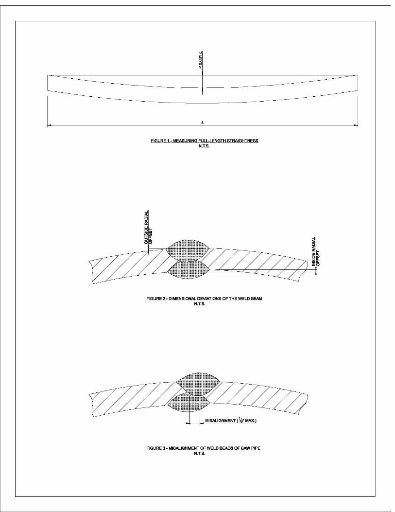
a. Out-of-Roundness : The out-of-roundness tolerance shall be within 1% of the nominal outside diameter. b. Straightness : The straightness, in units of inches, shall not exceed 0.001 times the length of the pile. The length of the pile shall be measured in inches. See Appendix A, Figure 1 for additional clarification. c. Radial Offset : A maximum radial offset of 1/8 inch shall be permitted. The offset shall be transitioned with a taper weld at the slope not less than 1 times the thickness on 2.5 times the length. See Appendix A, Figure 2 for additional clarification. d. Weld Reinforcement (Bead Height) : The weld reinforcement (bead height) shall not be greater than 3/16 inch. e. Misalignment of Weld Beads : Misalignment of the weld beads shall not exceed 1/8 inch. This applies only to double-sided welded pipe. See Appendix A, Figure 3 for additional clarification. f. Wall Thickness : The wall thickness shall be as indicated on the Contract Drawings except that up to a 10% greater thickness will be acceptable. g. Outside Diameter : The outside diameter shall be as indicated on the Contract Drawings except that a greater diameter will be acceptable. See item f. above.
2.1.2 Weld Material The weld material shall conform to the requirements in the AWS Filler Metal Specification for carbon steel using the SAW process (A5.17). 2.2 SHOP TESTING Nondestructive examination shall be performed on all SWP piles in accordance with AWS D1.1 Clause 6.
Testing Agency : The nondestructive examination of welds and the evaluation of examination tests as to the acceptability of the welds shall be performed by a testing agency adequately equipped and competent to perform such services or by the Contractor using suitable equipment and qualified personnel. The laboratory,
- 10 -
and all personnel performing nondestructive testing, shall be qualified in accordance with ASNT CP 189. In either case written approval of the examination procedures is required and the examination tests shall be made in the presence of the Contracting Officer. The evaluation of examination tests shall be subjected to Government approval. All records shall be become the property of the Government. Examination Procedures : Nondestructive testing shall comply with AWS D1.1 Clause 6, criteria for ‘Statically Loaded Nontubular Connections’. Specifically, visual inspection is required for 100% of all welds. Additionally, 25% of all spiral welds and 100% of all horizontal butt splice welds shall be tested by ultrasonic or radiographic testing for groove welds. Welds not passing the test shall be repaired and retested to assure compliance. Additionally, UT will be performed in-line on 100% of the spiral weld for the purpose of identifying defects. The defects shall then be tested in accordance with AWS D1.1 Clause 6. Acceptability of Welds : Welds shall be unacceptable if shown to have defects prohibited by AWS D1.1, Clause 6 for ‘Statically Loaded Nontubular Connections’, or possess any degree of cracks, or shows incomplete fusion or inadequate penetration. When doubt exists as to the soundness of any material part, such part may be subjected to any form of nondestructive testing as determined by the Contracting Officer. The costs of this investigation will be borne by the Government. Any defects will be cause for rejection and the rejected parts shall be replaced and retested at the Contractor’s expense.
2.3 REPAIRS Repairs shall be accomplished in accordance with AWS D1.1 paragraph 5.26. Defective weld material shall be removed by air carbon-arc or oxygen gouging to sound material. The surfaces shall be thoroughly cleaned before re-welding. When deemed necessary by the Contracting Officer, the Contractor shall submit a welding repair plan for approval before such ,repairs are made. Welds that have been repaired shall be 100% retested by the same testing methods as used in the original inspection. Testing shall extend a minimum of 3 inches beyond the limits of the repair. All costs associated with the repairs and retesting shall be borne by the Contractor.
PART 3 EXECUTION 3.1 INSTALLATION PART I
3.1.1 PILE DRIVING EQUIPMENT The Contractor shall select the proposed pile driving equipment as specified and submit descriptions of the proposed equipment for approval. Equipment approval will be based on the Contractor’s wave equation analysis and the engineering judgment of the Contracting Officer. Stresses predicted by wave equation analysis shall not exceed 80%
- 11 -
of the specified yield stress (Fy) of the steel, this is not to be confused with the yield stress as indicated in the mill test certifications. In addition, the maximum dynamic stresses during restrike shall also not exceed 80% of the specified yield stress. Final approval of the proposed equipment is subject to the satisfactory completion of the test pile installation. Changes in the selected pile driving equipment will not be allowed after the equipment has been approved by the Contracting Officer except as directed by the Contracting Officer. No additional contract time will be allowed for Contractor proposed changes in the equipment. 3.1.1.1 Pile Driving Hammers Pile driving hammers shall be of the impact type and shall be capable of satisfying the requirement of paragraph ‘Penetration Criteria’. Vibratory type hammers will be allowed on a limited basis subject to the approval of the Contracting Officer and provided the applicable requirements at the end of this paragraph are satisfied. Permanent and test piles shall be driven with hammers of the same efficiency and with the same driving system. Hammers shall be air or diesel hammers of the single acting, double-acting, or differential acting type. The size or capacity of hammers shall be a minimum of 20,000 foot-pounds. The maximum size of the hammer shall be determined for each diameter and wall thickness of SWP piles to be driven. The dynamic stresses induced in the piles from the selected hammer shall not exceed the stresses as specified in paragraph 3.1.1. Compressor, or engine capacity shall be sufficient to operate the hammers continuously at the full rated speed so that a single-acting hammer obtains a full upward stroke of the ram, a double-acting hammer operates at or near the blows per minute at which the hammer is rated, and a differential type hammer obtains a slight rise of the hammer base during each upward stroke. Single-acting hammers shall have a scale in inches fixed to the hammer's ram guide and a pointed indicator fixed on the ram to allow reading of the hammer's stroke. Both the scale and indicator shall be easily legible to observers on the ground. Hammers shall have a gage to monitor hammer bounce chamber pressure for diesel hammers or pressure at the hammer for air hammers. This gage shall be operational during the driving of piles and shall be mounted in an accessible location for monitoring by the Contractor and the Contracting Officer. Two spare operational bounce chamber readout units shall be available on site. The Contractor shall provide bounce chamber pressure gage correction tables and charts for the type and length of hose to be used with the pressure gage to the Contracting Officer. The following information for each hammer proposed shall be submitted: (1) Make and model. (2) Ram weight (pounds). (3) Anvil weight (pounds). (4) Weight of the moving parts of the hammer (pounds). (5) Rated stroke (inches). (6) Rated energy range (foot-pounds). (7) Rated speed (blows per minute). (8) Air pressure, hammer and/or compressor (pounds per square inch).
- 12 -
(9) Rated bounce chamber pressure curves or charts, including pressure correction chart for type and length of hose used with pressure gage (pounds per square inch). (10) Power pack description. When a vibratory hammer is used, the Contractor will be required to perform duplicate pile tests for the vibratory hammer at his expense. If increased pile lengths are required because of the vibratory hammer, the Contractor shall bear the cost of the added pile lengths. 3.1.1.2 Pile Driving Leads (or Templates) Leads shall align the pile and hammer concentrically and maintain the pile in proper position and alignment throughout driving. Hammers shall be supported and guided with suspended leads, fixed extended leads or fixed underhung leads. For driving battered piles, hammers shall be supported and guided with fixed extended leads capable of achieving the batters shown on the plans. The leads shall be of sufficient length to fully accommodate the combined length of the pile and hammer. Two intermediate pile supports shall be provided in the leads to reduce the unbraced length of the pile during driving and pulling. In the case of using a template in lieu of driving leads, the Contractor shall provide lateral support for the pile during driving. At least one intermediate support of the pile in the template is required to reduce the unbraced length of the pile during driving. 3.1.1.3 Driving Helmets A driving helmet shall be used between the top of the pile and the ram to prevent impact damage to the pile. The driving helmet shall be capable of protecting the head of the pile, minimize energy absorption and dissipation and transmit hammer energy uniformly over the top of the pile during driving. The driving helmet shall fit loosely around the top of the pile so that the pile is not restrained by the helmet if the pile tends to rotate during driving. Submit the pile driving helmet, make and model, and the weight of the helmet, in pounds, to the Contracting Officer for approval. 3.1.1.4 Cap Blocks (Hammer Cushions) The cap block (hammer cushion) used between the driving cap and the hammer ram may be of solid hardwood block with grain parallel to the pile axis and enclosed in a close-fitting steel housing or it may consist of aluminum and approved industrial type plastic laminate disks stacked alternately in a steel housing. Steel plates shall be used at the top and the bottom of the cap block. The cap block shall be replaced if it has been damaged, highly compressed, charred, burned or has become spongy or deteriorated in any manner. If a wood cap block is used, it shall not be replaced during the final driving of any pile. Under no circumstances will the use of small wood blocks, wood chips, rope, or other material permitting excessive loss of hammer energy, be permitted. 3.1.1.5 Pile Extractors
- 13 -
Impact hammers or vibratory hammers can be used for pulling SWP piles. 3.1.2 Pile Follower A follower will be allowed to reach the correct pile top elevation when either driving in water or when driving below ground surface. If a follower is used, the wave equation analysis should include the follower. 3.2 INSTALLATION PART II 3.2.1 Lengths of Permanent Piles The estimated quantities of piles listed in the unit price schedule are given for bidding purposes only. The Contracting Officer will determine the actual lengths of piles required to be driven below cutoff elevation for the various locations within the work area and will furnish the Contractor a quantities list indicating lengths and locations of all piles to be placed. Pile length determination will be made from the results of the pile tests specified in Section 31 62 14.00 12 ‘Pile Load Tests’ of the Contract Specifications. Production pile lengths for SWP’s driven with a vibratory hammer will in no case be shorter than production pile lengths determined from the testing program for piles driven with an impact hammer. Longer length production piles may be required if the use of a vibratory hammer is elected by the Contractor and the pile test program shows longer piles are required when installed with a vibratory hammer. 3.2.2 Pile Placement and Tolerances A pile placement plan shall be developed to show the installation sequence and the methods proposed for controlling the location and alignment of piles and shall be submitted for approval. Piles shall be placed accurately in the correct location and alignments, both laterally and longitudinally, and to the vertical or batter lines indicated. The Contractor shall establish a permanent baseline during pile driving operations to accommodate the inspection of pile placement by the Contracting Officer. The baseline shall be established prior to driving permanent piles and shall be maintained during the installation of the permanent piles. Prior to driving and with the pile head seated in the hammer, the Contractor shall check each pile for correct alignment. The alignment of battered piles shall be checked and monitored during driving with an accurate batter board level and surveying instrument. A final lateral deviation from the correct location at the cutoff elevation or top of pile elevation of not more than 3 inches will be permitted. A vertical deviation from the correct cutoff elevation shown on the drawing of not more than 1 inch will be permitted. The correct relative position of all piles shall be maintained by the use of templates or by other approved means. Piles not located properly or exceeding the maximum limits for lateral deviation, and/or variation in alignment shall be pulled and redriven at a directed location. 3.2.3 Pile Driving
- 14 -
Piles shall not be driven within 100 feet of concrete less than 7 days old nor within 30 feet of concrete less than 28 days old unless otherwise authorized. The sequence of installation shall be such that pile heave and lateral displacement is minimized. Where heave is anticipated, pile driving shall start at the center of the group and proceed outward and vertical piles shall be driven prior to those battered where practicable. The Contracting Officer shall be notified 30 days prior to the date driving is to begin. 3.2.3.1 Driving Records The pile driving record, for the Contractors use, can be found in Appendix C of this specification. Pile driving records shall include pile dimensions and location, pile identification number, manufactured date, date driven, original pile length, cutoff and tip elevations, batter alignment, description of hammer used, rated hammer energy, observed stroke and rate of hammer operation (blows per minute), air pressure at the hammer or bounce chamber pressure, length of pressure hose, penetration under the combined weight of the pile and hammer, number of blows required for each foot of penetration throughout the entire length of each pile and for each inch of penetration in the last foot of penetration, time for start and finish of driving, total driving time in minutes and seconds for each pile, cushion information including changes during driving, PDA information and any other information as required or requested. The record shall also include information such as unusual driving conditions, interruptions or delays during driving, observed pile damage, vertical heave or lateral displacement detected in adjacent piles, records of restriking, depth and description of voids formed adjacent to the pile and any other pertinent information. For piles driven with a vibratory hammer the cumulative time of penetration at five foot intervals shall be recorded throughout the entire length of each pile. Also, the butt elevation shall be recorded upon completion of the pile driving. Other pertinent information may be required to be recorded by the Contractor at the direction of the Contracting Officer. 3.2.3.2 Penetration Criteria Piles shall be driven to the required depth of penetration as shown on the drawings. The required depth of penetration will be established subsequent to the analysis of pile tests as specified in Section 31 62 14.00 12 ‘Pile Load Tests’ of the Contract Specifications. 3.2.3.3 Driving a. Permanent and test piles shall be driven with hammers of the same energy and efficiency, and using the same driving system. The hammer shall be operated at all times at the speed and under the conditions recommended by the manufacturer and consistent with the assumptions used in the wave equation analysis subject to the approval of the Contracting Officer. Once pile driving has begun, conditions such as alignment and batter shall be kept constant. Each pile shall be driven continuously and without interruption until the required depth of penetration has been attained. Deviation from this procedure will be permitted only for necessary changes or whenever driving is stopped by causes
- 15 -
that reasonably could not have been anticipated. A pile that cannot be driven to the required depth because of an obstruction or damage to the pile, as indicated by a sudden unexplained change in blow count and drifting, shall be pulled and redriven or shall be cut off and abandoned, whichever is directed. b. A pile which cannot be driven to the required tip elevation with the approved hammer shall be reported to the Contracting Officer. The Contracting Officer will direct the Contractor to cut off the pile, pull and redrive the pile, or perform other corrective measures. Corrective measures may consist of adding a pile at an adjacent location as determined by the Contracting Officer. c. For a driven pile that has not attained sufficient resistance or blow count per depth of penetration when the pile head is at the established cut- off elevation, the Contracting Officer may direct the Contractor to continue driving until such resistance is attained and extend the seated pile up to the specified cut-off elevation by splicing. The required resistance or blow count per depth of penetration will be determined by the Contracting Officer upon completion of the pile test program. Splicing of driven piles shall conform to the requirements of paragraph ‘Splicing’. d. Observations shall be made to detect heave and lateral displacement in accordance with paragraph ‘Heaved and Laterally Displaced Piles’. After piles are driven, any excess pile above the cutoff elevation shall be removed in accordance with paragraph ‘Cutting of Piles’. e. When using a vibratory hammer, if the pile tip does not move more than 0.10 foot per minute, the Contractor shall immediately attempt driving the pile with an impact hammer conforming to paragraph 3.1.1.1 3.2.3.4 Heaved and Laterally Displaced Piles When driving piles in clusters or under conditions of relatively close spacing, observations shall be made to detect the vertical heave or lateral displacement of adjacent piles. Heaved piles shall be restruck sufficiently to relieve soil setup and driven to the original penetration criteria. Laterally displaced piles shall be remediated as per the Contracting Officer’s instructions. 3.2.3.5 Pulled Piles (Damaged and Misplaced Piles) Piles damaged or impaired for use during driving shall be pulled and replaced with new piles, or shall be cut off and abandoned and new piles driven as directed. The Contracting Officer may require that any pile be pulled for inspection. Piles pulled at the direction of the Contracting Officer and found to be in suitable condition shall be redriven at a directed location. Any pile which is damaged because of internal defects or by improper handling or driving, or which is otherwise damaged by fault of the Contractor so as to impair it for its intended use, or any pile driven out of proper location, shall be removed and replaced. All work of removal and cost of replacement shall be
- 16 -
borne by the Contractor at no additional expense to the Government. The Contracting Officer may require the Contractor to pull certain selected piling after driving for inspection to determine the condition of the piling. Any pile so pulled and found to be damaged to such extent as, in the opinion of the Contracting Officer, would impair its usefulness in the completed structure, shall be removed from the site of the work and the Contractor shall furnish and drive a new pile to replace the damaged pile. Piling pulled and found to be sound and in a satisfactory condition as determined by the Contracting Officer's Representative shall be redriven. Any holes which remain as a result of pulling operations shall be filled as specified in paragraph ‘Void Backfill’. 3.2.3.6 Jetting Jetting of piles will not be permitted. 3.2.3.7 Preboring Preboring will be allowed on a limited basis subject to the approval of the Contracting Officer. When allowed, it shall be controlled such that the prebored hole is not larger than two thirds of the pile diameter and the prebore shall extend not more than two thirds of the designed pile embedment depth. 3.2.3.8 Void Backfill Voids occurring around piles as a result of pile driving or due to any other cause and abandoned holes for piles that have been pulled shall be filled to within 3 feet of the adjacent ground surface with a tremie-placed slurry (from bottom to top of hole). The slurry shall consist of one part Portland cement, two parts bentonite, and six parts sand mixed with enough water to produce a slurry viscous enough to thoroughly fill the voids. The upper 3 feet of the hole shall be filled with earth and compacted to the same density as the surrounding soil. The density of the surrounding soil shall be determined by the Contractor and submitted to The Contracting Officer for concurrence. 3.2.3.9 Cutting of Piles The proposed method for cutting of piles must be approved and shall not damage the pile. The use of explosives will not be permitted. Cut off sections of piles shall be removed from the site. 3.2.3.10 Welding
Perform shop and field welding, qualification of welders, qualification of welding machines and inspection of welds in accordance with AWS D1.1. Shop welding shall be accomplished by mechanized SAW aided by a laser vision or mechanical seam tracker. Shop and field welds shall be full penetration and shall be in compliance with AWS D1.1.
- 17 -
3.2.3.11 Splicing
a. Splices may be used after the splice details and methods have been reviewed and approved by the Contracting Officer. Note that prefabricated and mechanical splices will not be allowed. No more than two splices per full length of pile will be permitted. No splice will be permitted within the upper third of the pile or in the portion of the pile within five feet of the maximum tensile stress as located in the pile and shown on the Contract Drawings. If circumstances dictate that this requirement be violated, then the locations of the splice and details of the splice, will be submitted to the Designer of Record for approval. The splices shall be able to develop 100% of the pile structural capacity. Lateral joints shall be made with a continuous full penetration butt weld in accordance with AWS D1.1. Backer rings will be allowed. Backer rings shall meet the following criteria ; (1) They shall be a minimum of 3/8 inch thick. (2) Splicing in the backer rings shall be made by full penetration welds.
(3) Attachment of the rings to the pipe shall be done by using the minimum size and spacing of tack welds that will securely hold the backing ring in place. (4) Tack welding shall be done in the root area of the weld splice. (5) The gap between the backing ring and the pipe wall shall be no greater than 5/64 inch.
b. Unless reduced by an approved WPS, the minimum preheat and interpass temperature for splice welding and for making repairs shall be 150 degrees F regardless of the pipe wall thickness. In the event welding is disrupted, preheating to 150 degrees F must occur before welding is resumed. Welds shall not be water quenched but allowed to cool unassisted to ambient temperature.
3.3 STRUCTURAL AND WELDING TESTS Favorable results for these tests are required before driving of piles can begin ; CVN Impact Test : Charpy V Notch (CVN) testing shall be conducted in accordance with ASTM A370. A CVN impact test shall be conducted on the base metal once per heat and shall be conducted on the weld metal once per 50 piles. A minimum average absorbed energy of 20 foot-pounds and the minimum individual value of 15 foot-pounds shall be obtained at 0 degrees Fahrenheit. Tests shall be conducted for each different SWP pile section. Results of Macrotech Test : The weld specimens shall be prepared with a finish suitable for macrotech examination. A suitable solution shall be used for etching to give a clear definition of the weld. The weld shall have complete joint penetration, thorough fusion between weld metal and base metal, no cracks and no undercut exceeding 1/32 inch. Results of Selected Test Coupons
- 18 -
3.4 TESTING OF MECHANICAL PROPERTIES Favorable results of these tests are required before the driving of piles can begin ; 3.4.1 Tensile Tests 3.4.1.1 Tensile Testing Specimens Tensile test orientation shall be relative to the pile. At the option of the manufacturer, the specimen may be either full section, strip specimen or round bar specimen. 3.4.1.2 Tensile Testing Frequency Tensile tests shall be made at the frequency of one per 50 piles. 3.4.1.3 Longitudinal Tensile Tests At the option of the manufacturer, longitudinal tests may utilize a full specimen, or for pipe with a wall thickness greater than ¾ inch, a ½ inch diameter round bar specimen. The strip specimen shall be tested without flattening. 3.4.1.4 Transverse Tensile Tests The transverse tensile properties shall be determined as follows : The yield strength, ultimate strength and elongation values shall be determined on a flattened rectangular specimen. The same method of testing shall be employed for all lots for a given pile diameter and wall thickness. All specimens shall represent the full wall thickness of the pipe from which the specimen was cut. 3.4.1.5 Weld Tensile (Reduced Section Tension) Tests The weld tensile test specimens shall be taken at 45 degrees to the weld with the weld at the center, and shall represent the full wall thickness of the pipe from which the specimen was cut. Weld reinforcement shall not be removed unless directed by the Contracting Officer. 3.4.2 Flattening Tests Flattening tests shall be performed as directed. 3.4.3 Guided – Bend Tests The test specimens shall be taken from the spiral welded pipe of each combination of outside diameter and wall thickness containing skelp weld ends. The specimens shall not contain repair welds. Tests shall be in accordance with AWS D1.1, Clause 4. One test per 50 piles.
- 19 -
APPENDIX A Dimensional Tolerances Supplemental Sketches This appendix supplements the dimensional tolerances as specified in paragraph 2.1.1.2., specifically ; Figure 1 supplements 2.1.1.2.b, ‘Straightness’ Figure 2 supplements 2.1.1.2.c, ‘Radial Offset’ Figure 3 supplements 2.1.1.2.e, ‘Misalignment of Weld Beads’
- 20 -
- 21 -
APPENDIX B Engineering Notes SCOPE : These instructions are to be used with the Spiral Welded Pipe Pile Specification as developed by The Innovation Team for use in The New Orleans District. The pile design, installation and execution shall be in accordance with all provisions of EM 1110-2-2906 ‘Design of Pile Foundations‘, UFC 3-220-01A ‘Deep Foundations’ and the instructions contained herein. Other Corps of Engineers EM’s, UFC’s, TI’s and ETL’s may be applicable. In addition to the Corps of Engineers resources noted above, API RP 2A ‘Recommended Practice for Planning, Designing and Constructing Fixed Offshore Platforms – Working Stress Design’, is an excellent technical guide for both the structural and geotechnical aspects of pile design. Note that procedures for developing structural and geotechnical pile load tests, for the use of SWP piles in locations other than New Orleans, can be found in Appendix M of the main report. SPECIFIC INSTRUCTIONS : 1. The format of this specification is based on Corps of Engineers Guide Specification 31 62 23.13 ‘Cast-In-Place Concrete Piles, Steel Casing’. 2. Consideration should be given to making the test piles part of the permanent production piles. 3. These engineering notes should be jointly reviewed by the structural engineer of record and the geotechnical engineer of record. 4. Some specifications allow dynamic stresses as high as 90% of yield, however it is recommended that they be kept at, or below, 80% of yield for this specification. CAPWAP and PDA shall be completed in general accordance with ASTM D4945. Overwelded joints do not perform very well in a dynamic environment. One example would be that AASHTO does not recommend overweld for welded bridge girders subjected to repeated vehicle loads. See specification section 2.1.1.2.d for weld reinforcement ( weld bead ) height. Note that this specification does not require that the weld beads be ground flush. 5. Note that the ductility ratio of 2 is based on the structural performance as well as the weld performance. See ‘Additional Discussion on Ductility’ contained herein. 6. Note that the design stresses in the spiral welded pipe piles placed under this specification shall be limited to 67% of yield. 7. This specification covers spiral welded pipe piles that are subjected to single axis bending in combination with axial tension or compression. Piles subject to double axis bending and/or torsion are not covered under this specification. Note that the ductility acceptance criteria accounts for infrequent or rare eccentric lateral overloads that are transmitted through the rigid pile cap to the pile heads as shearing forces and bending
- 22 -
moments. Only incidental torsion and/or biaxial bending may occur within the pile group as designed for use with this specification. 8. A rigid pile cap is assumed for use with this specification. The pile cap shall be able to transmit forces to the piles in proportion to the relative rigidities of the individual piles. In no case shall the stiffness of the pile cap be less than 10 times the combined stiffness of the individual piles. 9. This specification does not apply to single pile supported structures. 10. This specification applies to piles that are assumed to be either pinned or fixed into the pile cap. Note that for a pile that is assumed as fixed, the pile must extend a minimum of two pile diameters into the pile cap. Also, the requirement as stated in paragraph 3.2.3.11 of the specification ‘No splice will be permitted within the upper third of the pile or in the portion of the pile within five feet of the maximum tensile stress as located in the pile and shown on the Contract Drawings’ will insure that no splices will occur near the point of maximum bending in the pile. 11. When the center of mass of the pile cap is eccentric to the center of rigidity of the pile group, the designer must account for the additional moment that will be transmitted to the piles. 12. This specification covers spiral welded pipe piles from 18 to 54 inches in outside diameter with a wall thickness not greater than 1 1/8 inch. The diameter to wall thickness ratio shall not exceed 55. D/t ratios not exceeding 60 will be allowed if the design provides for such and is supported by classical design methods, finite element analysis and structural tests results that show the pipe meets the ductility requirements of performing adequately (no localized buckling and no weld degradation) up to a ductility ratio of 2. See ‘Additional Discussion on Ductility’ contained herein. 13. This specification covers battered piles to a maximum batter of 3-H on 12-V. 14. The clear spacing of the piles covered under this specification shall not be less then 3 outside pile diameters. Also, the end clear distance, at construction joints and at the end of the wall, shall not be less then 2 feet. 15. To account for possible eccentricity at field splices, the pile design shall account for an additional moment equal to the axial load times the actual eccentricity, with the minimum eccentricity being ½ inch. 16. The pile design shall account for the additional moment due to the axial load times the eccentricity occurring from the pile not being absolutely straight. The eccentricity shall be determined from the dimensional tolerances indicated in paragraph 2.1.1.2.b. ‘Straightness’, of the specification.
- 23 -
17. The maximum tensile stress location in the pile shall be shown on the contract drawings. 18. The minimum specified design yield stress of pile base material, covered under this specification, shall be not less than 46 ksi. ADDITIONAL DISCUSSION ON DUCTILITY : Spiral welded pipe (SWP) piles have spiral, skelp and/or splice welds that may be located in or near regions of maximum stresses, these welds ultimately control the structural performance of the pile. A series of four point flexural tests (FPFT) were conducted at North Carolina State University (NCSU) to determine the ductility level at which failure occurred, and to establish the maximum dependable ductility level corresponding to significant degradation of strength and stiffness. The tests were conducted in a test frame using two 220 kip actuators that created a 12 foot long constant moment region in a 36 foot long SWP pile. The loading applied to each test specimen included three standard sets of cyclic loads. This loading established the elastic yield and inelastic post yield response of the the SWP piles. Each test was preceded by a moment-curvature (M-PHI) analysis that was used to predict the first yield moment (My), force, curvature and displacement and the plastic moment capacity (Mp) of the SWP pile cross section. The M-PHI analysis was used to divide the pre-yield loading sequence into four test stages that ramped up to the first yield force and the corresponding average first yield displacement (Dy). A value defined as ductility level 1 (u1) was calculated by amplifying the measured first yield displacement by the ratio of Mp to My, i.e., u1 = Dy*Mp/My. The post yield stages of each test were completed in controlled increments of displacement ductility until failure occurred. The displacement associated with ductility level 2 (u2) was twice the value of u1, and the displacement associated with ductility level 3 was three times the value of u1. A finite element analysis confirmed the results of the FPFT. Note : For a complete discussion on ductility, D/t ratios and FPFT test results, see the main body of the report. DEFINITION OF DUCTILITY LEVELS: Ductility Level 1 is the displacement (u1) computed by increasing the maximum displacement (Dy) measured in the constant moment region of a FPFT by the ratio of the predicted plastic moment capacity (Mp) to the yield moment (My). Higher ductility levels (uJ) are multiples (J*u1) of ductility level 1. ACCEPTANCE CRITERIA: All of the test results to date show that failure of the SWP piles initiated as local inelastic buckling of the wall and progressed to a rupture of the wall in the buckled area. This general observation of the test results indicates that, for the current weld quality, all SWP piles only experienced local wall buckling during ductility level 2 followed by the onset
- 24 -
of failure during different loading cycles in ductility level 3. Based on these test results, and interpretative analyses using classical beam and finite element models, ductility level 2 shall be established as the acceptance criteria. The maximum ratio of external pile diameter (D) to pile wall thickness (t) shall be limited to 55. The use of this criteria will prevent premature local wall buckling before the onset of ductility level 2. (Additional FPFT for larger D/t ratios may lead to increasing this limit to 60 as permitted in AWS D1.1 Provision 2.20.2). In addition to the D/t limitations, the weld ductility shall pass the guided bend test per AWS D1.1 Provision 4.8.3.3, or the minimum required strain level at the onset of ductility level 2, whichever is greater.
- 25 -
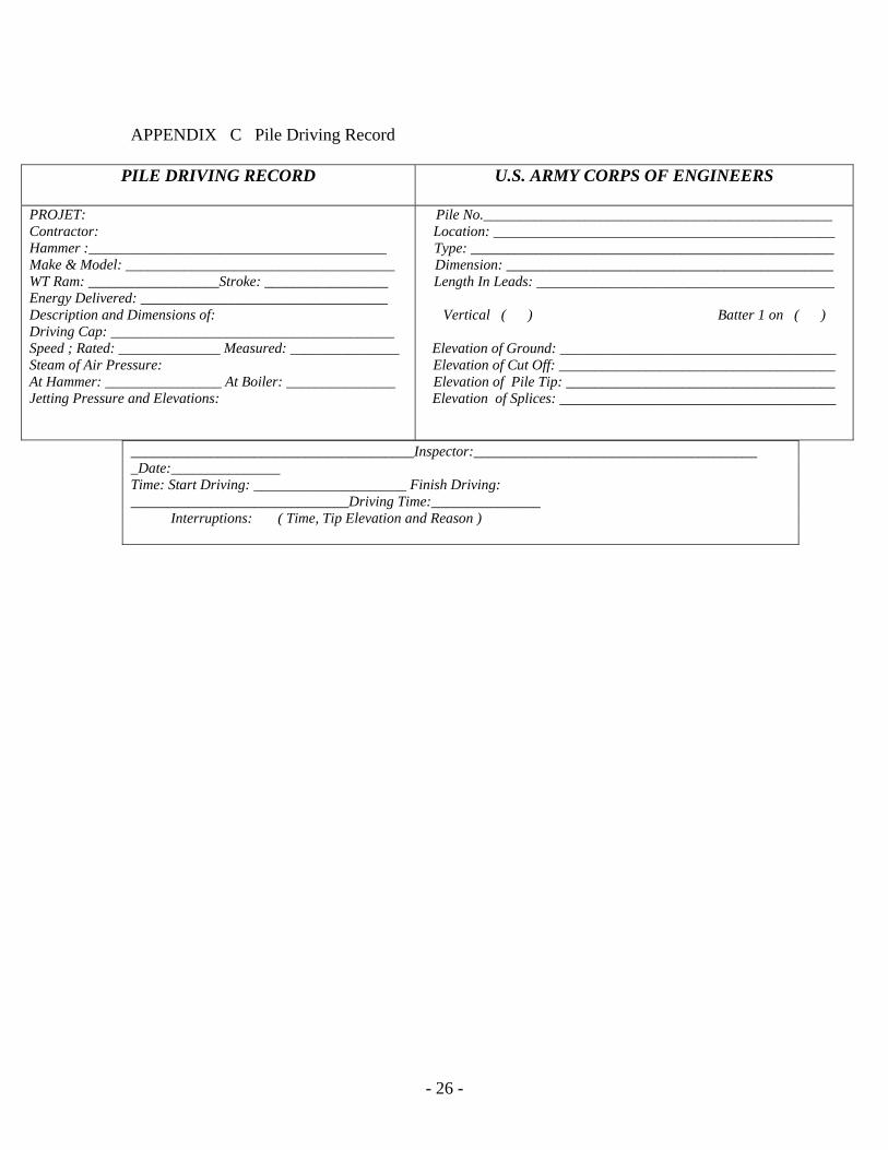
APPENDIX C Pile Driving Record
PILE DRIVING RECORD U.S. ARMY CORPS OF ENGINEERS
PROJET: Contractor: Hammer :_________________________________________ Make & Model: _____________________________________ WT Ram: __________________Stroke: _________________ Energy Delivered: __________________________________ Description and Dimensions of: Driving Cap: _______________________________________ Speed ; Rated: ______________ Measured: _______________ Steam of Air Pressure: At Hammer: ________________ At Boiler: _______________ Jetting Pressure and Elevations:
Pile No.________________________________________________ Location: _______________________________________________ Type: __________________________________________________ Dimension: _____________________________________________ Length In Leads: _________________________________________
Vertical ( ) Batter 1 on ( )
Elevation of Ground: ______________________________________ Elevation of Cut Off: ______________________________________ Elevation of Pile Tip: _____________________________________ Elevation of Splices: ______________________________________
_______________________________________Inspector:________________________________________Date:_______________ Time: Start Driving: _____________________ Finish Driving: ______________________________Driving Time:_______________ Interruptions: ( Time, Tip Elevation and Reason )
- 26 -
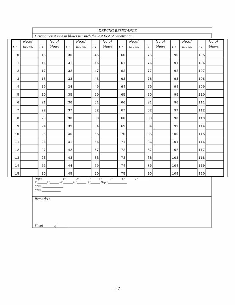
DRIVING RESISTANCE
Driving resistance in blows per inch the last foot of penetration:
- 27 -
Depth ____________ 1”_______ 2”______ 3”______4”______5”_______6”_______ 7”________ 8”_______9”_______10”_______11”_______12”_______ Depth______________
FT
No.of
b lows FT
No.of
b lows FT
No.of
b lows FT
No.of
b lows FT
No.of
b lows FT
No.of
b lows FT
No.of
b lows FT
No.of
b lows
0 15 30 45 60 75 90 105
1 16 31 46 61 76 91 106
2 17 32 47 62 77 92 107
3 18 33 48 63 78 93 108
4 19 34 49 64 79 94 109
5 20 35 50 65 80 95 110
6 21 36 51 66 81 96 111
7 22 37 52 67 82 97 112
8 23 38 53 68 83 98 113
9 24 39 54 69 84 99 114
10 25 40 55 70 85 100 115
11 26 41 56 71 86 101 116
12 27 42 57 72 87 102 117
13 28 43 58 73 88 103 118
14 29 44 59 74 89 104 119
15 30 45 60 75 90 105 120
Elev. ____________ Elev.___________
Remarks : Sheet _____of _____