wafer-level packaging of aln-based piezoelectric...
TRANSCRIPT
WAFER-LEVEL PACKAGING OF ALN-BASED
PIEZOELECTRIC MICROPOWER GENERATORS
C. Schröder*, F. Senger, F. Stoppel, B. Wagner and W. Benecke
Fraunhofer Institute for Silicon Technology ISIT, Itzehoe, Germany
Abstract: This paper presents vacuum wafer-level packaging of resonant piezoelectric micropower generators
based on AlN by means of glass frit bonding in combination with lateral electrical feedthroughs. To minimize
mechanical losses due to parasitic fluidic damping and improve mechanical stability special top and bottom caps
with integrated mechanical stoppers and getter films have been used. In order to determine the quality of the
generator packaging, different tests with respects to mechanical stability, hermeticity, vacuum level and stopper
functionality have been done.
Keywords: piezoelectric, micropower, generator, AlN, wafer-level, packaging, vacuum, glass frit, getter
INTRODUCTION Piezoelectric micropower generators for ambient
vibration energy harvesting are typically set up as
resonating systems, designed to work at oscillation
frequencies of a few hundred hertz and external
acceleration amplitudes below 5 m/s² [1]. As a
consequence these systems are fragile and sensitive,
while they are supposed to operate under harsh
environmental conditions for a long period of time to
overcome commercial batteries. Therefore they need
to be protected by a reliable packaging, which in the
most cost-effective way is realized at wafer-level.
Since packaging of piezoelectric micropower
generators can end in a drastically reduced power
output due to high mechanical losses caused by
parasitic fluidic damping [2], it is essential to perform
the wafer-level packaging under vacuum.
EXPERIMENTAL Generator Redesign
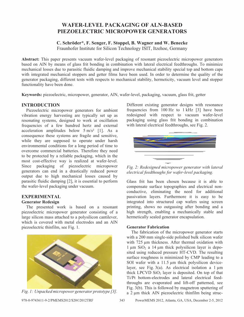
The presented work is based on a resonant
piezoelectric micropower generator consisting of a
large silicon mass attached to a polysilicon cantilever,
which is covered with metal electrodes and an AlN
piezoelectric thinfilm, see Fig. 1.
Fig. 1: Unpacked micropower generator prototype [3].
Different existing generator designs with resonance
frequencies from 100 Hz to 1 kHz [3] have been
redesigned with respect to vacuum wafer-level
packaging using glass frit bonding in combination
with lateral electrical feedthroughs, see Fig. 2.
Fig. 2: Redesigned micropower generator with lateral
electrical feedthoughs for wafer-level packaging.
Glass frit has been chosen because it is able to
compensate surface topographies and electrical non-
conductive, eliminating the need for additional
passivation layers. Furthermore it is easy to be
integrated into structured cap wafers using screen
printing, shows no outgassing after bonding and a
high strength, enabling a mechanically stable and
hermetically sealed generator encapsulation.
Generator Fabrication
The fabrication of the micropower generator starts
with a 200 mm single-side polished bulk silicon wafer
with 725 µm thickness. After thermal oxidation with
1 µm SiO2 a 14 µm thick polysilicon layer is depo-
sited using reduced pressure HT-CVD. The resulting
surface roughness is minimized by CMP leading to a
SOI wafer with a 11.5 µm thick polysilicon device-
layer, see Fig. 3(a). As electrical isolation a 1 µm
thick LPCVD SiO2 layer is deposited. On top of that
Ti/Pt bottom-electrodes and lateral electrical feed-
throughs are evaporated and lift-off patterned, see
Fig. 3(b). This is followed by magnetron sputtering of
a 2 µm thick AlN piezoelectric thinfilm being struc-
978-0-9743611-9-2/PMEMS2012/$20©2012TRF 343 PowerMEMS 2012, Atlanta, GA, USA, December 2-5, 2012
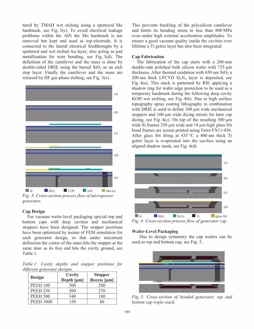
tured by TMAH wet etching using a sputtered Mo
hardmask, see Fig. 3(c). To avoid electrical leakage
problems within the AlN the Mo hardmask is not
removed but kept and used as top-electrode. It is
connected to the lateral electrical feedthroughs by a
sputtered and wet etched Au layer, also acting as pad
metallization for wire bonding, see Fig. 3(d). The
definition of the cantilever and the mass is done by
double-sided DRIE using the buried SiO2 as an etch
stop layer. Finally the cantilever and the mass are
released by HF gas-phase etching, see Fig. 3(e).
(a)
(b)
(c)
(d)
(e)
Si SiO2 Ti/Pt AlN Mo/Au
Fig. 3: Cross-section process flow of micropower
generator.
Cap Design
For vacuum wafer-level packaging special top and
bottom caps with deep cavities and mechanical
stoppers have been designed. The stopper positions
have been optimized by means of FEM simulation for
each generator design, so that under maximum
deflection the center of the mass hits the stopper at the
same time as its free end hits the cavity ground, see
Table 1.
Table 1: Cavity depths and stopper positions for
different generator designs.
Design Cavity
Depth [µm]
Stopper
Recess [µm]
PEEH 100 500 280
PEEH 250 500 270
PEEH 500 340 180
PEEH 1000 150 80
This prevents buckling of the polysilicon cantilever
and limits its bending stress to less than 800 MPa
even under high external acceleration amplitudes. To
ensure a good vacuum quality inside the cavities over
lifetime a Ti getter layer has also been integrated.
Cap Fabrication
The fabrication of the cap starts with a 200 mm
double-side polished bulk silicon wafer with 725 µm
thickness. After thermal oxidation with 650 nm SiO2 a
200 nm thick LPCVD Si3N4 layer is deposited, see
Fig. 4(a). This stack is patterned by RIE applying a
shadow ring for wafer edge protection to be used as a
temporary hardmask during the following deep cavity
KOH wet etching, see Fig. 4(b). Due to high surface
topography spray coating lithography in combination
with DRIE is used to define 300 µm wide mechanical
stoppers and 100 µm wide dicing streets for later cap
dicing, see Fig. 4(c). On top of the resulting 300 µm
wide Si frames 250 µm wide and 14 µm high glass frit
bond frames are screen printed using Ferro FX11-036.
After glass frit firing at 435 °C a 400 nm thick Ti
getter layer is evaporated into the cavities using an
aligned shadow mask, see Fig. 4(d).
(a)
(b)
(c)
(d)
Si SiO2 Si3N4 Ti glass frit
Fig. 4: Cross-section process flow of generator cap.
Wafer-Level Packaging
Due to design symmetry the cap wafers can be
used as top and bottom cap, see Fig. 5.
Fig. 5: Cross-section of bonded generator, top and
bottom cap triple-stack.
344

To protect the piezoelectric generator front side first
the top cap and then the bottom cap are aligned and
bonded to the generator wafer. This is done by
thermo-compressive bonding at 420 °C under vacuum
resulting in 300 µm wide and 7 µm thick glass frit
seal frames. To get access to the bond pads parts of
the top cap wafer are removed by dicing before final
die singulation.
DISCUSSION Mechanical Stability
The mechanical stability of the packaging has been
characterized using a conventional Dage PC2400 die
shear tester. Different top and bottom caps have been
sheared and the corresponding shear forces and shear
strengths have been measured. To get an idea about
the reliability of the packaging some of the devices
have been stressed in an additional pressure cooker
test (PCT) for 96 hours at 80 °C and 80 % relative
humidity prior to cap shear testing, see Table 2.
Table 2: Results from cap shear testing with and
without pressure cooker test (PCT).
Cap Shear
Force [N]
Shear
Strength [MPa]
Top 114.5 ± 21.4 18.0 ± 4.8
Top PCT 109.9 ± 34.3 17.4 ± 5.4 Bottom 158.9 ± 20.6 25.1 ± 3.2
While there is no difference in shear strength of top
caps with and without PCT a clear difference between
top and bottom caps is visible. The bond of the top
cap typically fails at the interface between the Ti/Pt
metal frame and the glass frit, see Fig. 6 and Fig. 7.
Fig. 6: Generator CAD including Ti/Pt bottom-
electrode (blue), glass frit bond frame (red) and Ti
getter layer (green).
Fig. 7: Optical microscope image after cap shear
testing showing poor glass frit adhesion on Ti/Pt
lateral electrical feedthrough.
In contrast to that the bond of the bottom cap typically
fails within the 300 µm wide Si frames. This indicates
a better glass frit adhesion on Si, SiO2 and Au than on
Ti/Pt and should be taken into account during the next
generator redesign by minimizing the Ti/Pt metal
areas. However the obtained results clearly show a
mechanically stable and reliable generator packaging.
Hermeticity and Vacuum-Level
First vacuum wafer-level packaged micropower
generator prototypes have been assembled on PCB
and connected by wire bonding, see Fig. 8.
Fig. 8: Vacuum wafer-level packaged micropower
generator prototype.
To test the hermetical integrity of the packaging
different generator prototypes have been mounted on
an electromagnetic shaker and exited by single
mechanical impulses, while their ring-down voltages
have been measured using a DAQ device. After an
initial set of measurements the generator prototypes
had to pass a neon bombing fine leak test for 24 hours
at 2.5 bar before all measurements have been repeated
again. The corresponding ring-down curves do not
show significant differences before and after neon
bombing, indicating a leak free and hermetically
sealed generator encapsulation, see Fig. 9.
345

0
25
50
75
100
125
150
0.0 0.5 1.0 1.5 2.0 2.5 3.0 3.5
Time [s]
Rin
gdo
wn V
ola
tag
e [
mV
] before neon bombing
after neon bombing
Fig. 9: Ring-down voltage of generator prototype
measured before and after neon bombing.
Based on the measured ring-down curves quality
factors of about 600 have been recalculated for
vacuum packaged prototypes after in-situ getter
activation during wafer bonding. In comparison to
first unpackaged prototypes with quality factors of
about 1100 [3], the vacuum packaged generator
prototypes still show an increased parasitic fluidic
damping, mainly due to glass frit outgassing during
wafer bonding. To overcome this an additional post
getter activation for 36 hours at 360 °C in a reduced
N2 atmosphere has been performed, leading to
increased quality factors of about 1400. In contrast to
that one generator prototype has been reopened for
pressure balancing by fine drilling, resulting in a
highly reduced quality factor of about 60, see Fig. 10.
0
25
50
75
100
125
150
0.0 0.5 1.0 1.5 2.0 2.5 3.0 3.5
Time [s]
Rin
gdow
n V
ola
tage [
mV
]
after in-situ getter activation
after post getter activation
after pressure balancing
Fig. 10: Ring-down voltage of generator prototype
measured after in-situ getter activation, post getter
activation and pressure balancing to atmosphere.
Stopper Functionality
The mechanical stoppers have been tested by using
the electromagnetic shaker again, applying sinusoidal
oscillations with varying frequencies and acceleration
amplitudes up to 40 m/s² while measuring the
generated output voltage. Once the acceleration
amplitude is high enough for the generator mass to hit
the mechanical stoppers the output voltage remains
constant even for higher acceleration amplitudes
because of a limited cantilever deflection. Due to
continuous upward frequency sweeps the measured
voltage curves show a virtual bandwidth extension up
to higher frequencies, which can not be found for
discrete frequency sweeps, see Fig. 11.
0
0.25
0.5
0.75
1
1.25
1.5
610 620 630 640 650 660 670 680
Frequecy [Hz]
Genera
ted V
oltage [V
]
1 m/s²
2 m/s²
3 m/s²
4 m/s²
5 m/s²
6 m/s²
7 m/s²
Fig. 11: Measured generator voltage under sinusoidal
oscillation with varying frequencies and acceleration
amplitudes showing influence of mechanical stopper.
CONCLUSION Piezoelectric micropower generators based on AlN
have been successfully vacuum wafer-level packaged
by means of glass frit bonding in combination with
lateral electrical feedthroughs. By using special top
and bottom caps with integrated mechanical stoppers
and getter films an improved mechanical stability as
well as a minimized parasitic fluidic damping have
been achieved. First vacuum packaged generator
prototypes showed quality factors of about 1400 after
post getter activation, outperforming unpackaged
generator prototypes with quality factors of about
1100. In addition the integrated mechanical stoppers
allowed external acceleration amplitudes of up to
40 m/s² without showing any degradation of the
generator performance.
REFERENCES
[1] Roundy S., Wright P.K., Rabeay J. 2003 A
Study of Low Level Vibrations as Power Source
for Wireless Sensor Nodes Comp. Comm. 26
1131-1144
[2] Elfrink R. et al. 2010 Vacuum-Packaged
Piezoelectric Vibration Energy Harvesters:
Damping Contributions and Autonomy for a
Wireless Sensor System J. Micromech.
Microeng. 20 1-7
[3] Schröder C. et al. 2011 AlN-based Piezoelectric
Micropower Generator for Low Ambient
Vibration Energy Harvesting Technical Digest
PowerMEMS 2011 (Seoul, Korea, 15-18
November 2011) 217-220
Frequency [Hz]
346