w. winkler anforderungen an die systemauslegung von ... · w. winkler anforderungen an die...
TRANSCRIPT
W. WinklerAnforderungen an die Systemauslegung von
Schiffsantrieben mit Brennstoffzellen(Requirements of system design of
ship propulsion with fuel cells)
Internationaler Congress für Schiffs-Technik (ICST)
Hamburg, 10.09.2015
Prof. Dr. techn. Wolfgang Winkler, Retired Director of
Institute for Energy Systems and Fuel Cell Technology

German and EU projects: FC ships
2002 2003 2004 2005 2006 2007 2008 2009 2010 2011
FCSHIP
FELICITAS
FellowSHIP
New H-SHIP
METHAPU
e4ships
ZEMSHIP
MC-WAP
U – 212/214 silent
H2
• Sustainable transportation principles
• All electric ship and system integration
• Hybrid system design
• Principles of fuel processing
• Principles of energy storage
• Engineering challenges
• Conclusion
• Sustainable transportation principles
• All electric ship and system integration
• Hybrid system design
• Principles of fuel processing
• Principles of energy storage
• Engineering challenges
• Conclusion
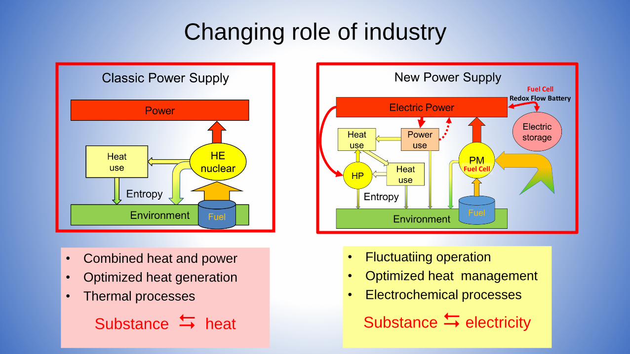
Changing role of industry
• Combined heat and power
• Optimized heat generation
• Thermal processes
Substance heat
• Fluctuatiing operation
• Optimized heat management
• Electrochemical processes
Substance electricity

Tool:Thermodynamics2nd law
Entropy flow of society as the scaleReversible process defines the ruleReversible process borderline of real process
Sustainable development realization
RealProcess
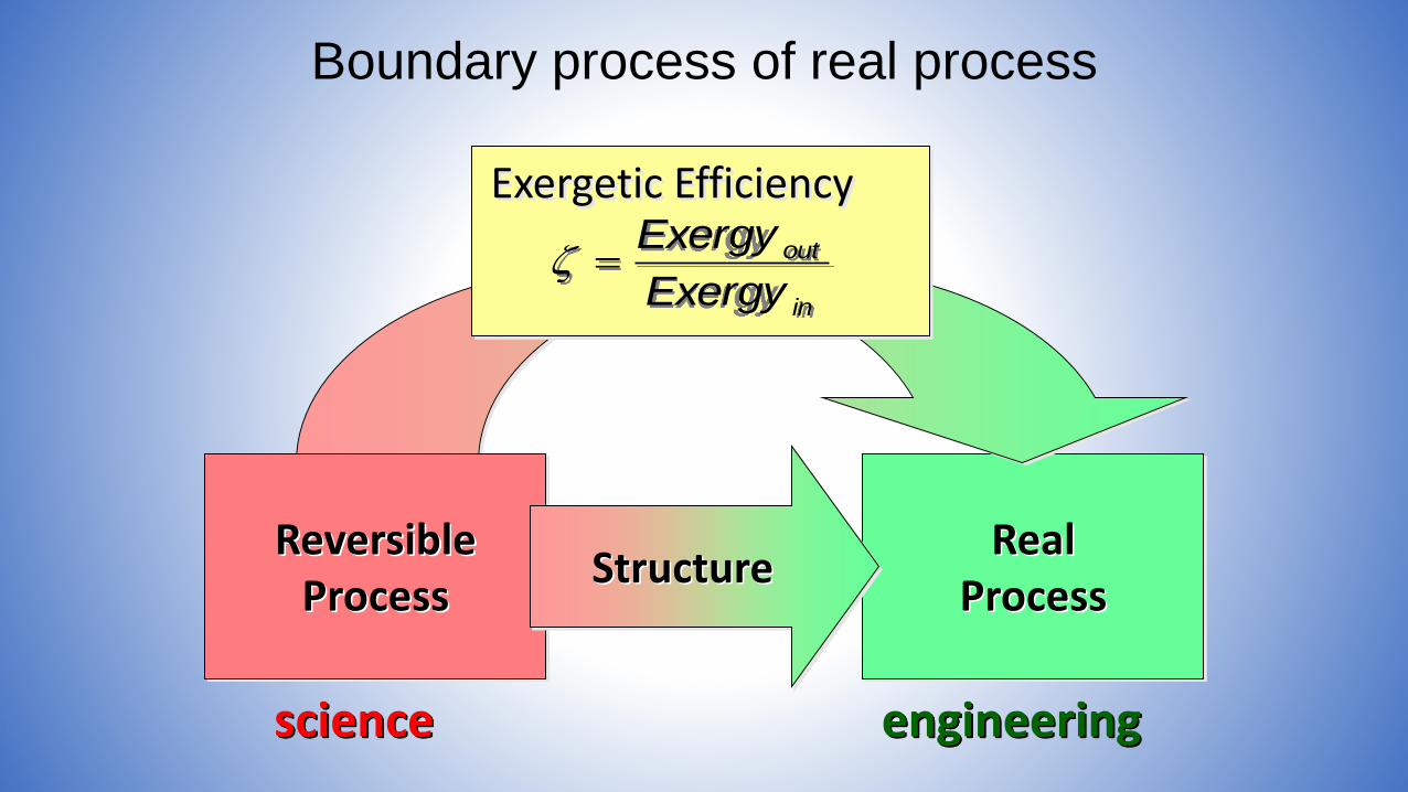
Boundary process of real process
in
out
Exergy
Exergy
Exergetic Efficiency
ReversibleProcess
science engineering
Structure

Visible irr. Entropy Production
(real)
Geometric description of
solution
Reversible Structure(virtual)
System designwithout decisionabout geometry
Boundaries of Reversibility
1
ζ

Overview reversible Processes
Potential difference h Potential difference Tsource - Tab
Chemical Potential
No reversible S Reversible S from:Tsource ΔS
Reversible S (ΔRS)
Reversible mechanical System
Reversible thermal System
Reversible chemical System
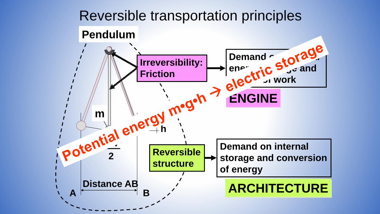
Distance AB
m•v²
2
A B
m•g•h
h
Reversible
structure
Irreversibility:
Friction
Demand on external
energy storage and
supply of work
ENGINE
Demand on internal
storage and conversion
of energy
ARCHITECTURE
Pendulum
m
Reversible transportation principles
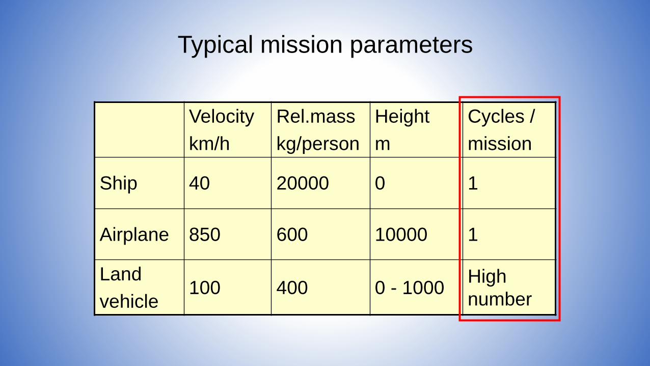
Typical mission parameters
Velocity
km/h
Rel.mass
kg/person
Height
m
Cycles /
mission
Ship 40 20000 0 1
Airplane 850 600 10000 1
Land
vehicle100 400 0 - 1000
High
number
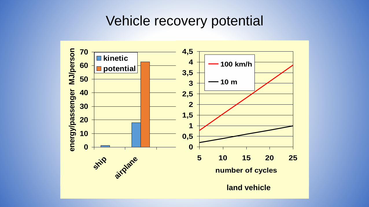
Vehicle recovery potential
0
10
20
30
40
50
60
70
ship
airp
lane
en
erg
y/p
assen
ger
MJ/p
ers
on
kinetic
potential
0
0,5
1
1,5
2
2,5
3
3,5
4
4,5
5 10 15 20 25
number of cycles
100 km/h
10 m
land vehicle

All-Electric systems with FC
Internal Recovery
Storage
Fuel Cell+
Fuel tank
Electric Storage
Friction determined
Recovery determined
Dissipation
Supply Storage
Land Vehicles Tra
nsp
ort
ati
on
syste
m
Ships
Airplanes
• Sustainable transportation principles
• All electric ship and system integration
• Hybrid system design
• Principles of fuel processing
• Principles of energy storage
• Engineering challenges
• Conclusion
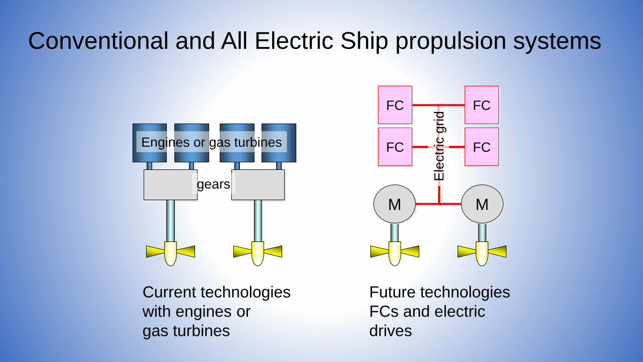
Conventional and All Electric Ship propulsion systems
Current technologies
with engines or
gas turbines
Engines or gas turbines
gears
M M
FC
FC FC
FC
Future technologies
FCs and electric
drives
Ele
ctr
ic g
rid
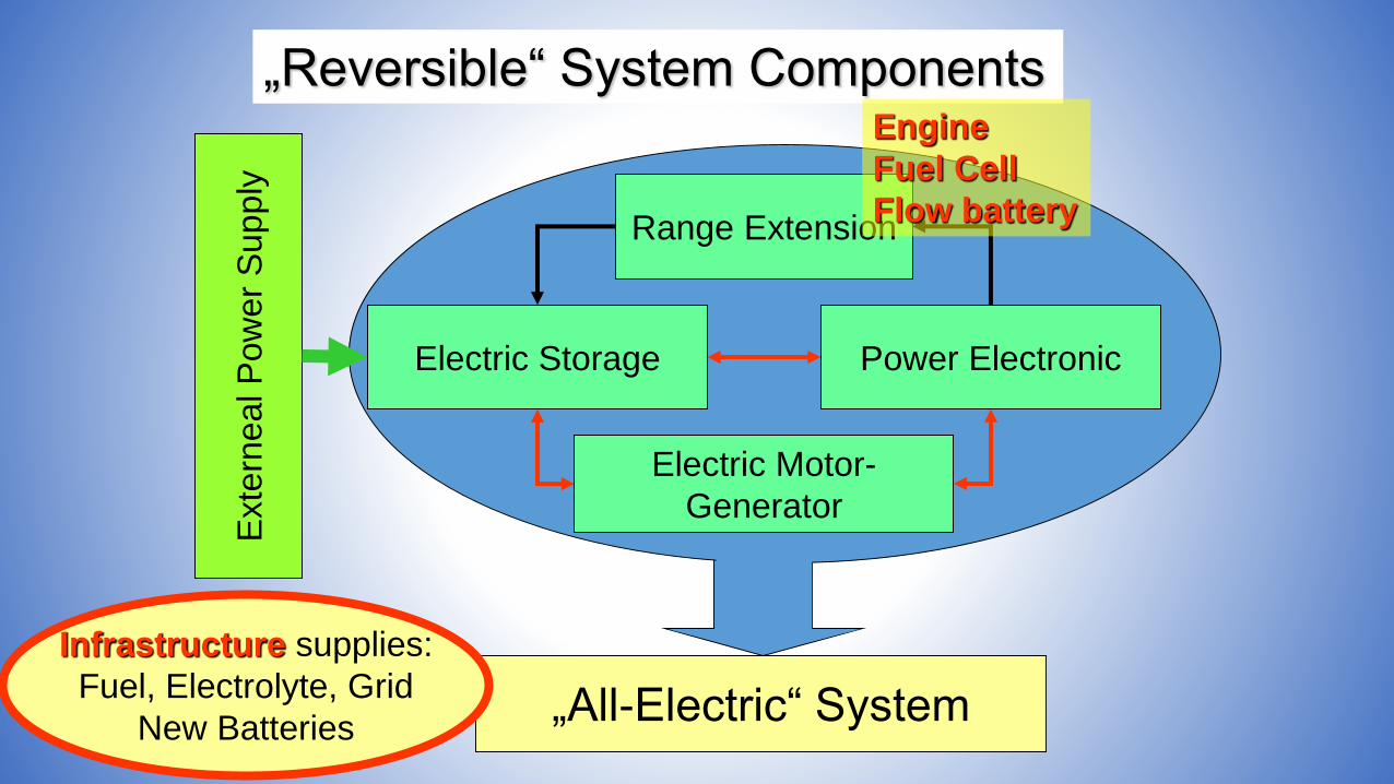
„Reversible“ System Components
„All-Electric“ System
Range Extension
Power Electronic
Electric Motor-
Generator
Electric Storage
Exte
rneal P
ow
er
Supply
Engine
Fuel Cell
Flow battery
Infrastructure supplies:
Fuel, Electrolyte, Grid
New Batteries
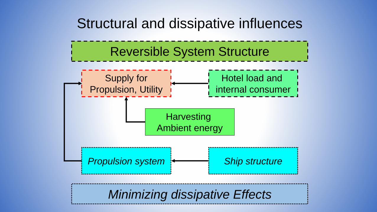
Reversible System Structure
Minimizing dissipative Effects
Harvesting
Ambient energy
Supply for
Propulsion, Utility
Hotel load and
internal consumer
Ship structurePropulsion system
Structural and dissipative influences
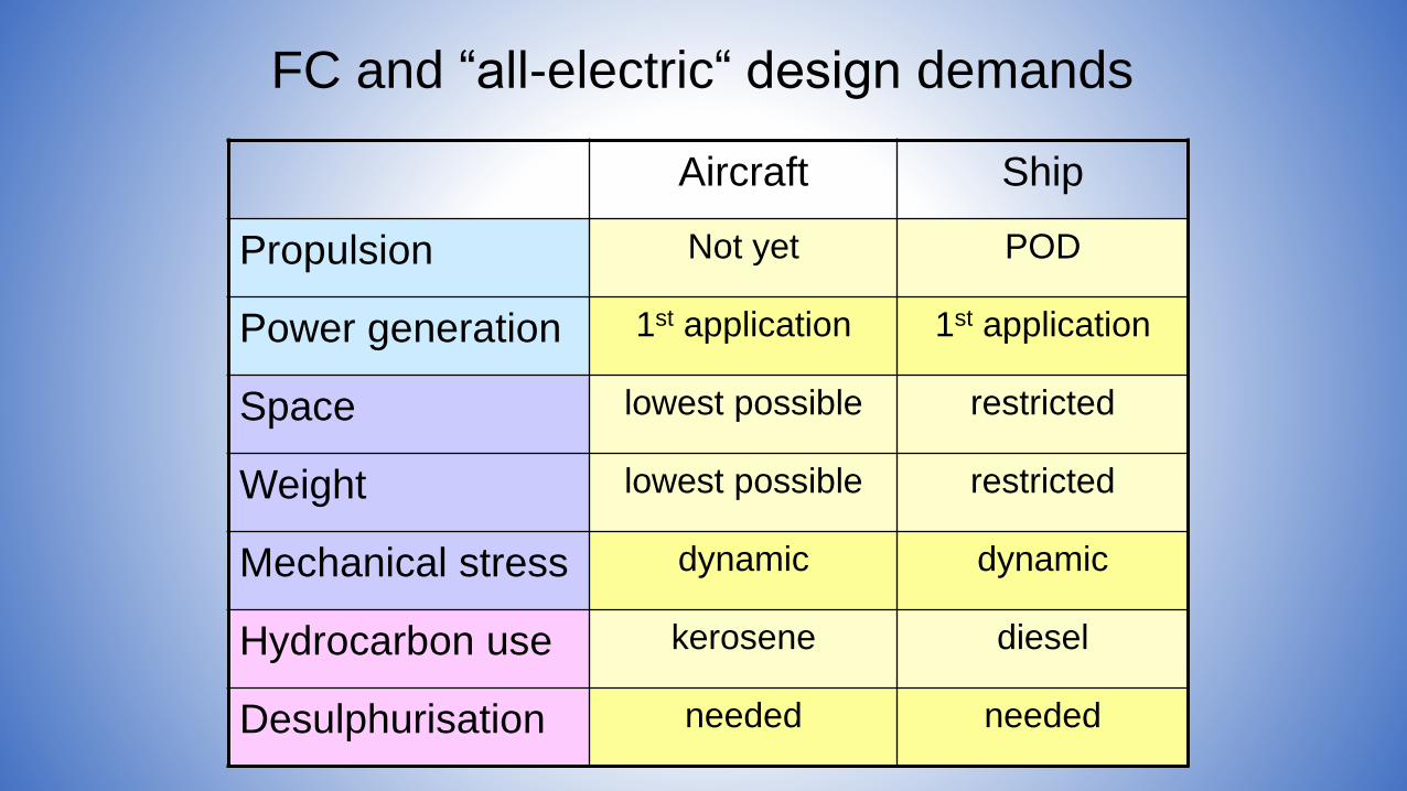
Aircraft Ship
Propulsion Not yet POD
Power generation 1st application 1st application
Space lowest possible restricted
Weight lowest possible restricted
Mechanical stress dynamic dynamic
Hydrocarbon use kerosene diesel
Desulphurisation needed needed
FC and “all-electric“ design demands
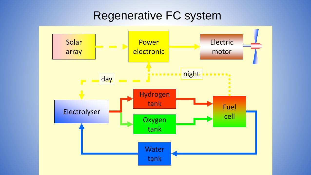
Watertank
Electrolyser
Powerelectronic
Hydrogentank
Oxygentank
Solararray
Electricmotor
Fuelcell
daynight
Regenerative FC system

Pathfinder Plus
(USA)
Regenerative all-electric aircraft/ship
Source: NASA/ONR
Solar Power and Wave Energies
AUV (Russia)
• Sustainable transportation principles
• All electric ship and system integration
• Hybrid system design
• Principles of fuel processing
• Principles of energy storage
• Engineering challenges
• Conclusion
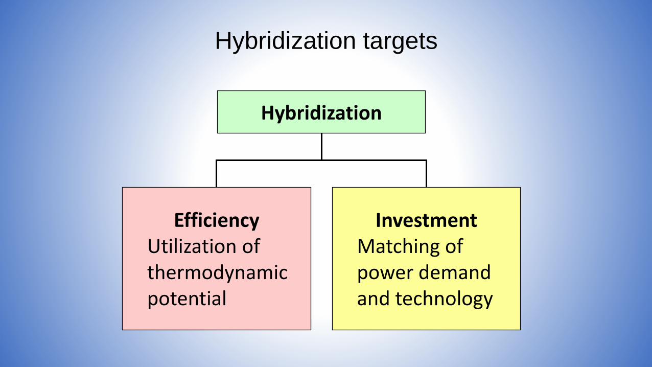
Hybridization targets
Hybridization
EfficiencyUtilization ofthermodynamicpotential
InvestmentMatching ofpower demandand technology
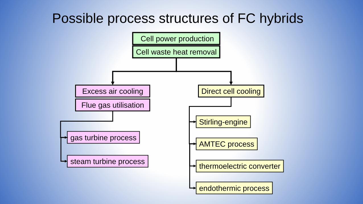
Cell waste heat removal
Excess air cooling Direct cell cooling
Cell power production
gas turbine process
steam turbine process
endothermic process
Stirling-engine
AMTEC process
thermoelectric converter
Flue gas utilisation
Possible process structures of FC hybrids
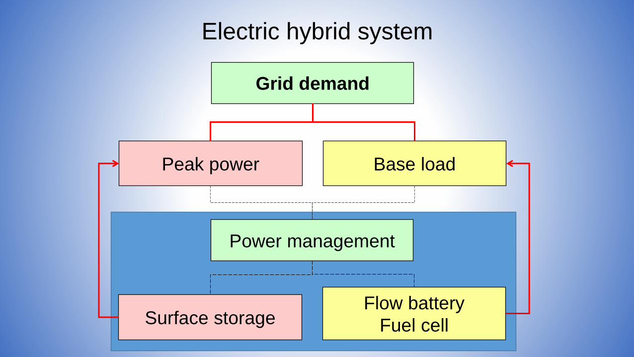
Electric hybrid system
Grid demand
Peak power Base load
Power management
Surface storageFlow battery
Fuel cell
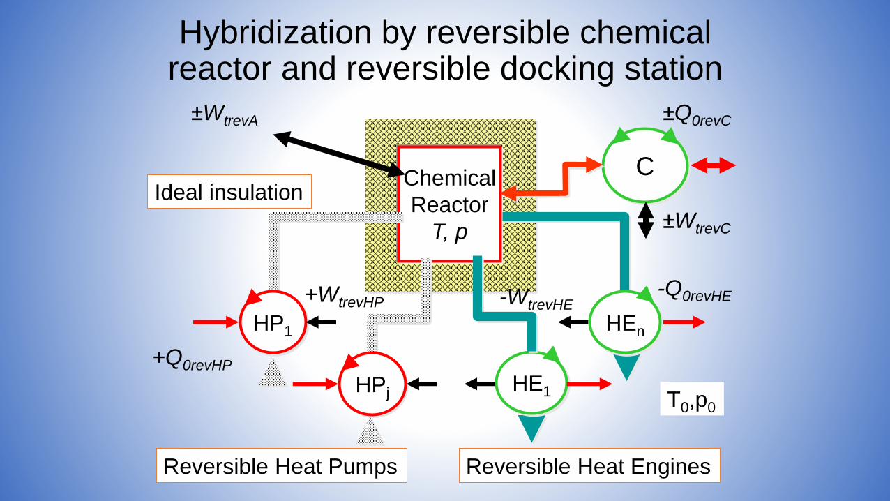
Chemical
Reactor
T, p
Ideal insulation
±WtrevA
T0,p0
-Q0revHE-WtrevHE
Reversible Heat Engines
HE1
HEnHP1
+Q0revHP
+WtrevHP
Reversible Heat Pumps
HPj
C
±Q0revC
±WtrevC
Hybridization by reversible chemicalreactor and reversible docking station
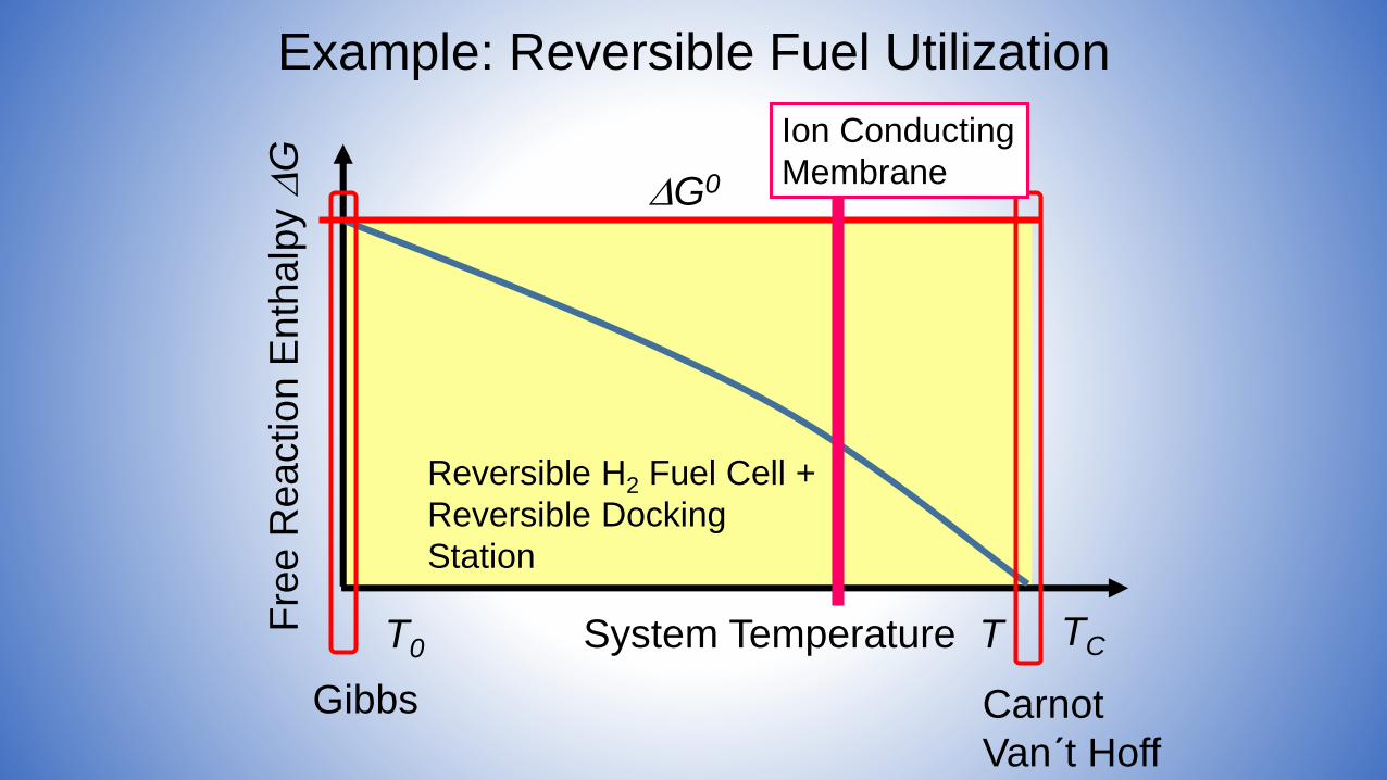
Reversible H2 Fuel Cell +
Reversible Docking
Station
Example: Reversible Fuel Utilization
System Temperature T
Gibbs Carnot
Van´t Hoff
G0
Fre
e R
eactio
n E
nth
alp
y
G
TCT0
Ion Conducting
Membrane
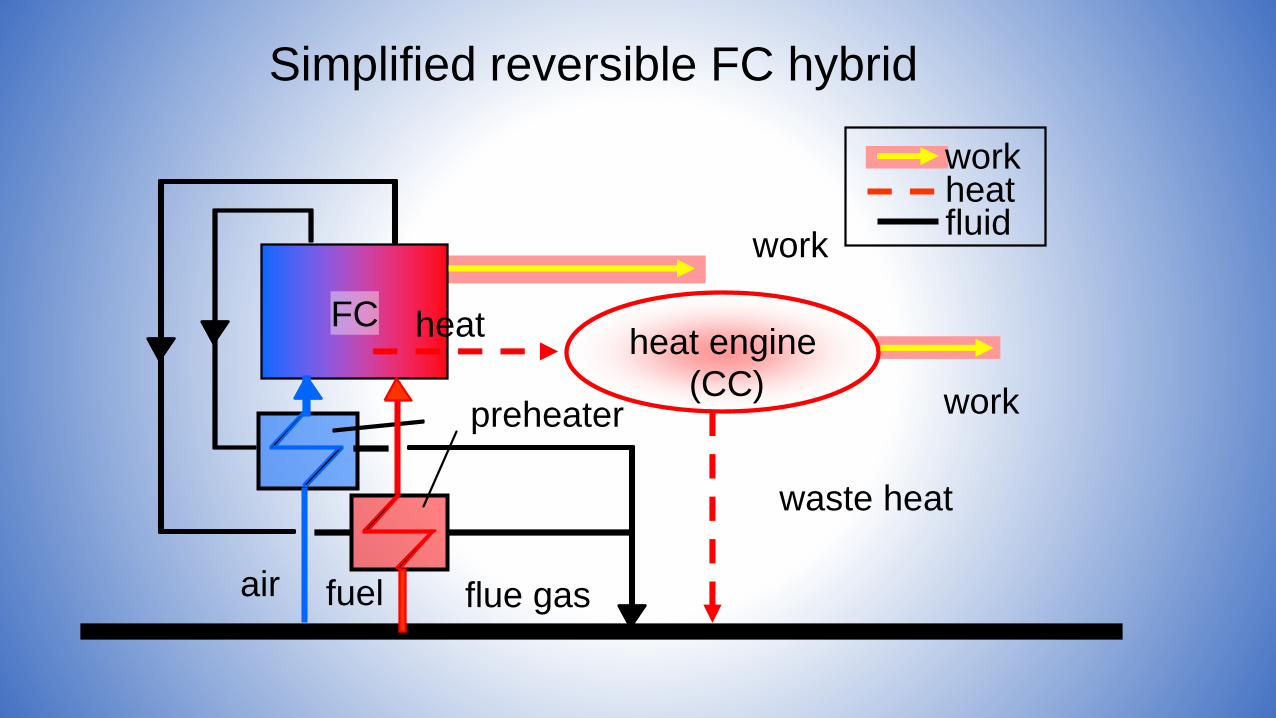
workheatfluid
Simplified reversible FC hybrid
work
flue gasair fuel
preheater
FC
waste heat
work
heatheat engine
(CC)
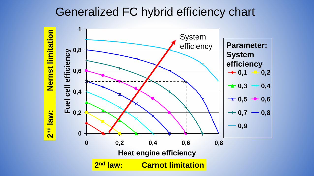
0
0,2
0,4
0,6
0,8
1
0 0,2 0,4 0,6 0,8
Heat engine efficiency
Fu
el c
ell e
ffic
ien
cy
0,1 0,2
0,3 0,4
0,5 0,6
0,7 0,8
0,9
Parameter:
System
efficiency
Generalized FC hybrid efficiency chart
System
efficiency
2nd law: Carnot limitation
2n
dla
w:
Nern
st
lim
itati
on

fuelairflue gas
reformer
SOFC waste heat extraction (sub-systems)
pressure difference HEX walls
air inlet temperature in SOFC
size of HEX surfaces
exhaust temperature
Intermediate expansion INEX :
Possible SOFC-GT systems
External cooling EXCO:
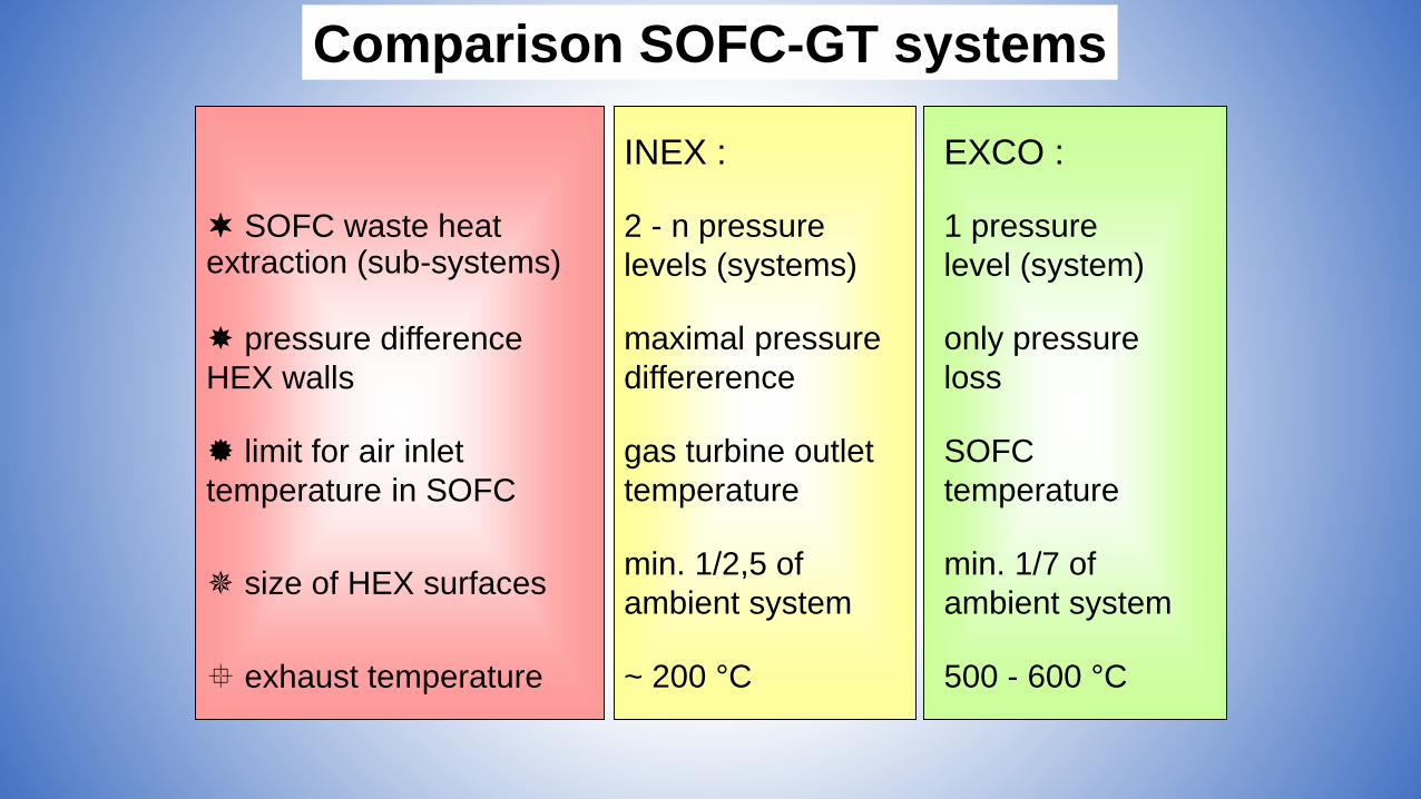
Comparison SOFC-GT systems
EXCO :INEX :
SOFC waste heat extraction (sub-systems)
1 pressure
level (system)
2 - n pressure
levels (systems)
pressure difference
HEX walls
only pressure
loss
maximal pressure
differerence
limit for air inlet
temperature in SOFC
SOFC
temperature
gas turbine outlet
temperature
size of HEX surfaces min. 1/7 of
ambient system
min. 1/2,5 of
ambient system
exhaust temperature 500 - 600 °C~ 200 °C
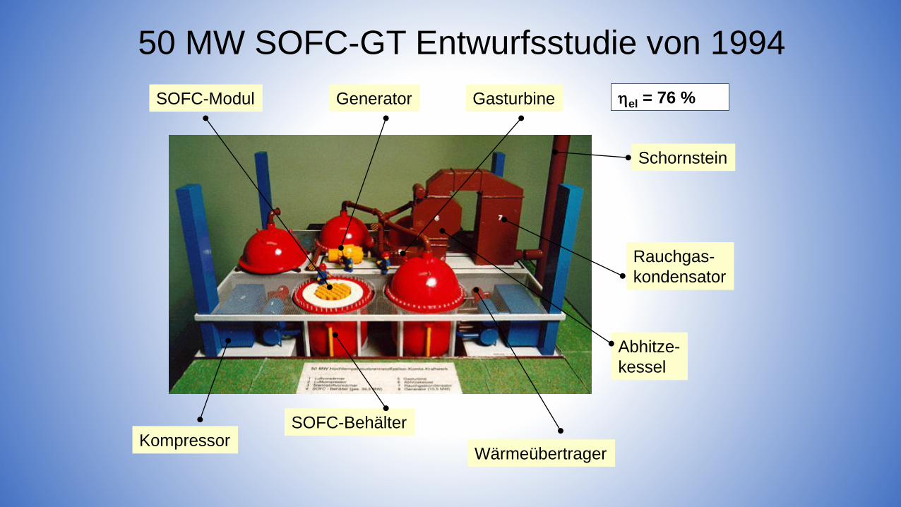
50 MW SOFC-GT Entwurfsstudie von 1994
SOFC-BehälterKompressor
Wärmeübertrager
GeneratorSOFC-Modul Gasturbine
Abhitze-
kessel
Rauchgas-
kondensator
Schornstein
el = 76 %
• Sustainable transportation principles
• All electric ship and system integration
• Hybrid system design
• Principles of fuel processing
• Principles of energy storage
• Engineering challenges
• Conclusion
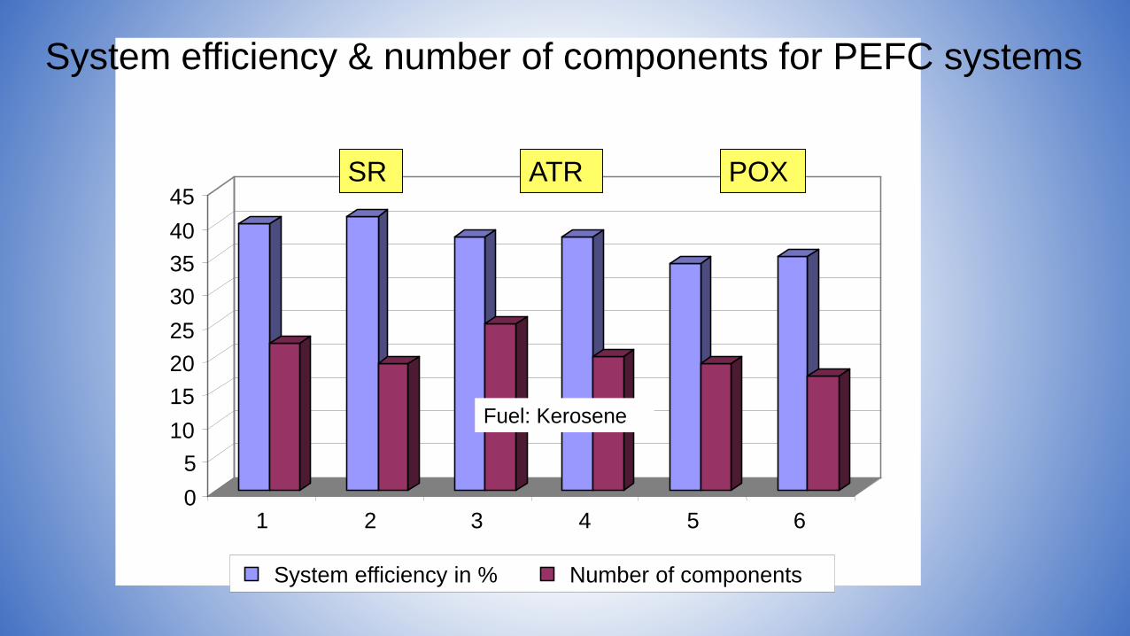
0
5
10
15
20
25
30
35
40
45
1 2 3 4 5 6
System efficiency in % Number of components
SR
System efficiency & number of components for PEFC systems
ATR POX
Fuel: Kerosene
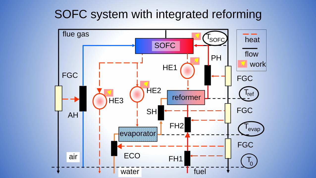
SOFC
HE3
HE2
heat
flow
SH
PH
flue gas
air
FGC
FGC
FGC
FGC
FH2
FH1ECO
AH
T
T
T
T
ref
SOFC
work
water fuel
evaporator
0
reformer
evap
HE1
SOFC system with integrated reforming
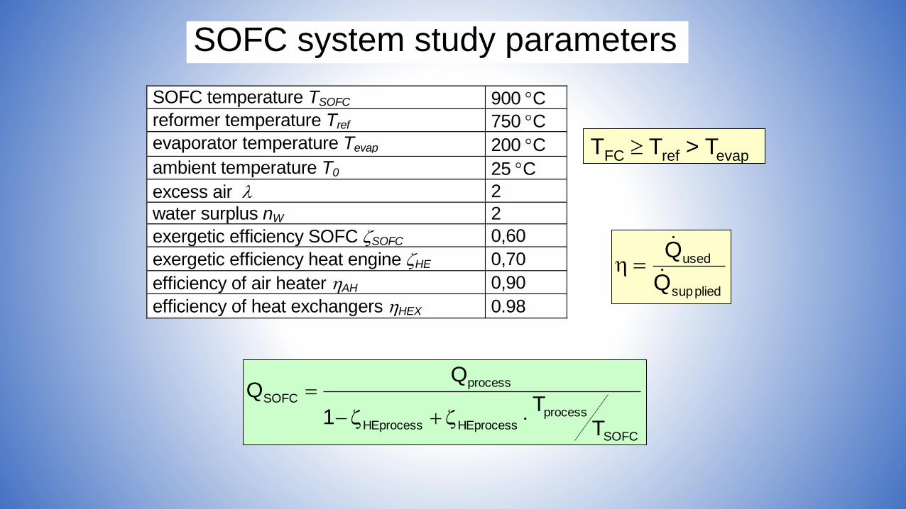
SOFC temperature TSOFC 900 C
reformer temperature Tref 750 C
evaporator temperature Tevap 200 C
ambient temperature T0 25 C
excess air 2
water surplus nW 2
exergetic efficiency SOFC SOFC 0,60
exergetic efficiency heat engine HE 0,70
efficiency of air heater AH 0,90
efficiency of heat exchangers HEX 0.98
SOFC
processHEprocessHEprocess
process
SOFC
TT
1
TFC Tref > Tevap
pliedsup
used
Q
Q
SOFC system study parameters
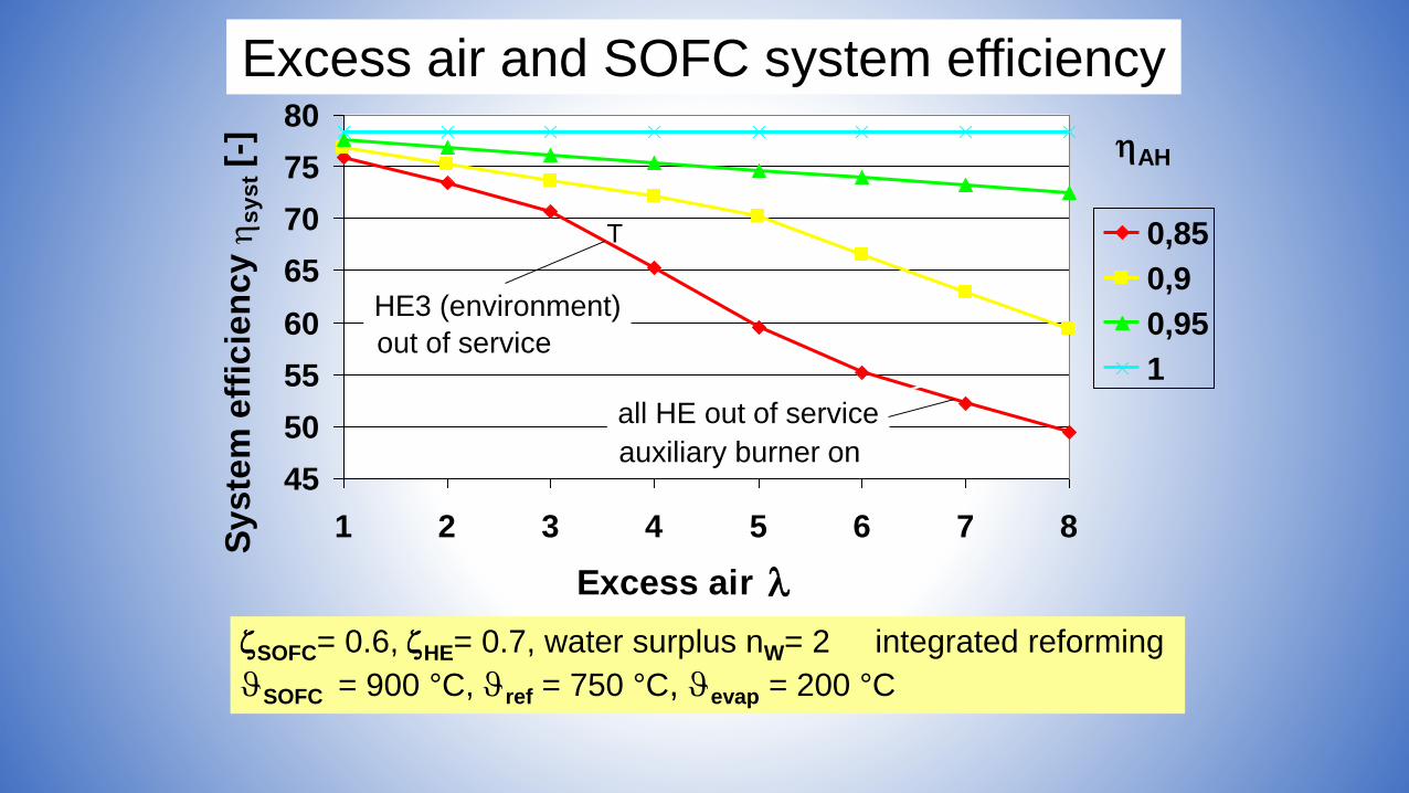
45
50
55
60
65
70
75
80
1 2 3 4 5 6 7 8
Excess air
Sy
ste
m e
ffic
ien
cy
s
ys
t [-]
0,85
0,9
0,95
1
SOFC= 0.6, HE= 0.7, water surplus nW= 2 integrated reforming
SOFC = 900 °C, ref = 750 °C, evap = 200 °C
AH
Excess air and SOFC system efficiency
HE3 (environment)
out of service
all HE out of service
auxiliary burner on
T

Integration of reforming
60
65
70
75
80
85
750 800 850 900 950 1000
SOFC Temperature in °C
Syste
m e
ffic
ien
cy in
% 0.6ext
0.6int
0.8ext
0.8intExternal reforming
Internal reforming
HE = 0.7 excess air = 2, excess water nW = 2
Tref = 750 °C, Tevap = 200 °C
SOFC
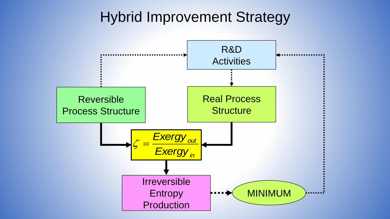
Hybrid Improvement Strategy
in
out
Exergy
Exergy
Reversible
Process Structure
Real Process
Structure
Irreversible
Entropy
Production
MINIMUM
R&D
Activities
• Sustainable transportation principles
• All electric ship and system integration
• Hybrid system design
• Principles of fuel processing
• Principles of energy storage
• Engineering challenges
• Conclusion
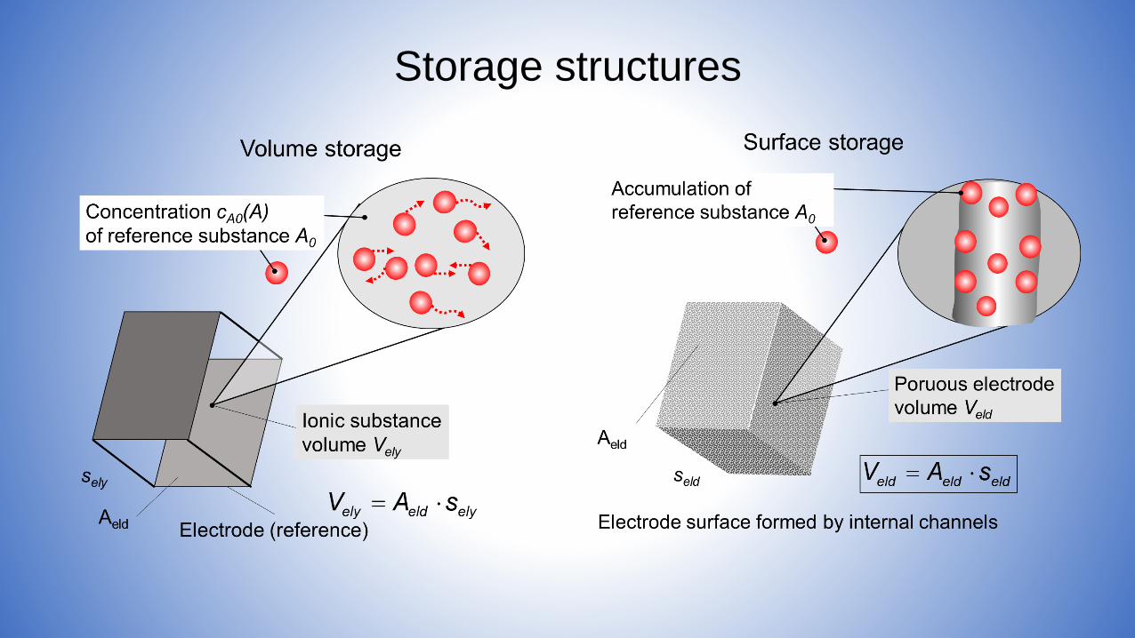
Storage structures
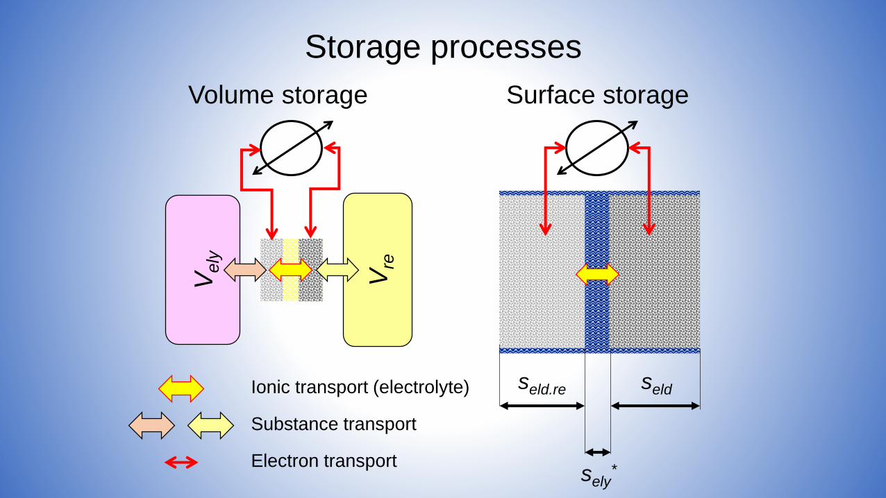
Ve
ly
Vre
Ionic transport (electrolyte)
Substance transport
Electron transport
Volume storage Surface storage
seldseld.re
sely*
Storage processes

Principal electrical storage processes
PM.ESmAelKM.ES.tel VFV)A(cnW 00
Stored electric work
VA SnAc *
0
*
0)(
Surface storageVolume storage
)(
)()(
0
00
AM
AAc
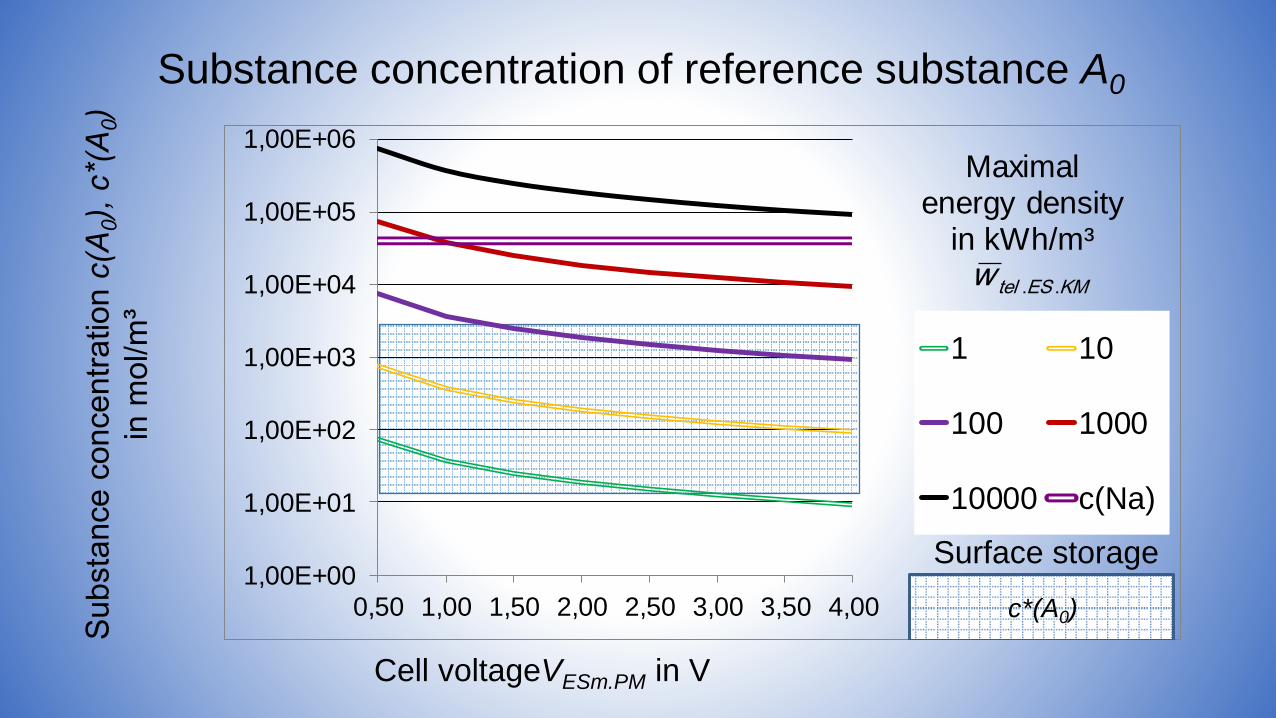
Substance concentration of reference substance A0
Cell voltageVESm.PM in V
KMEStelw ..
Surface storage1,00E+00
1,00E+01
1,00E+02
1,00E+03
1,00E+04
1,00E+05
1,00E+06
0,50 1,00 1,50 2,00 2,50 3,00 3,50 4,00
1 10
100 1000
10000 c(Na)
Maximalenergy density
in kWh/m³
c*(A0)
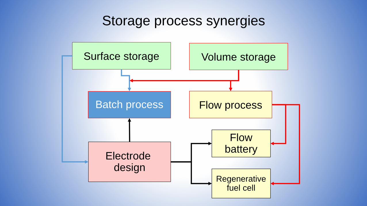
Storage process synergies
Volume storageSurface storage
Regenerative fuel cell
Flowbattery
Electrodedesign
Batch process Flow process

• Sustainable transportation principles
• All electric ship and system integration
• Hybrid system design
• Principles of fuel processing
• Principles of energy storage
• Engineering challenges
• Conclusion

Specific Weight of Energy Converters
Diesel Engines
0
5
10
15
20
25
30
0 5000 10000 15000 20000 25000
Capacity in kW
Sp
ecif
ic W
eig
ht
in k
g/k
W
Gasturbines
0,00
2,00
4,00
6,00
8,00
10,00
12,00
14,00
16,00
0,00 5000,00 10000,00 15000,00 20000,00 25000,00
Capacity in kW
Sp
ecif
ic W
eig
ht
in k
g/k
W
PEFC H2 Systems
0,00
10,00
20,00
30,00
40,00
50,00
60,00
70,00
0,00 1,00 2,00 3,00 4,00 5,00 6,00
Capacity in kW
Sp
ec
ific
We
igh
t in
kg
/kW
High Temperature FC Systems
0,00
50,00
100,00
150,00
200,00
250,00
300,00
350,00
0,00 500,00 1000,00 1500,00 2000,00 2500,00 3000,00 3500,00
Capacity in kW
Sp
ec
ific
We
igh
t in
kg
/kW
Source: www.dieselgasturbine.com, US Fuel Cell Council
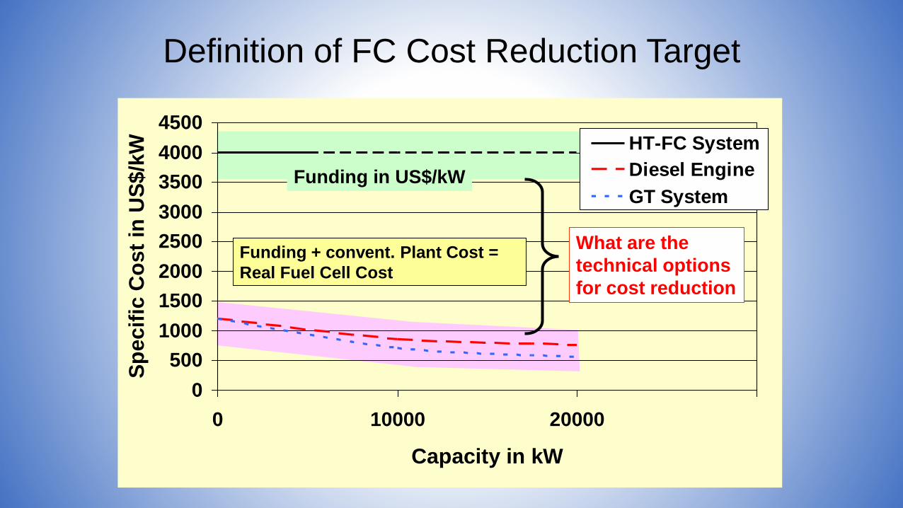
Definition of FC Cost Reduction Target
0
500
1000
1500
2000
2500
3000
3500
4000
4500
0 10000 20000
Capacity in kW
Sp
ecif
ic C
ost
in U
S$/k
W HT-FC System
Diesel Engine
GT System
Funding + convent. Plant Cost =
Real Fuel Cell Cost
Funding in US$/kW
What are the
technical options
for cost reduction
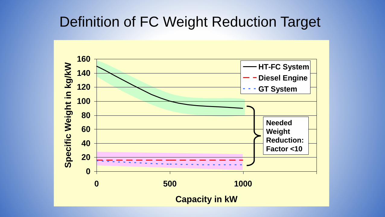
Definition of FC Weight Reduction Target
0
20
40
60
80
100
120
140
160
0 500 1000
Capacity in kW
Sp
ecif
ic W
eig
ht
in k
g/k
W HT-FC System
Diesel Engine
GT System
Needed
Weight
Reduction:
Factor <10
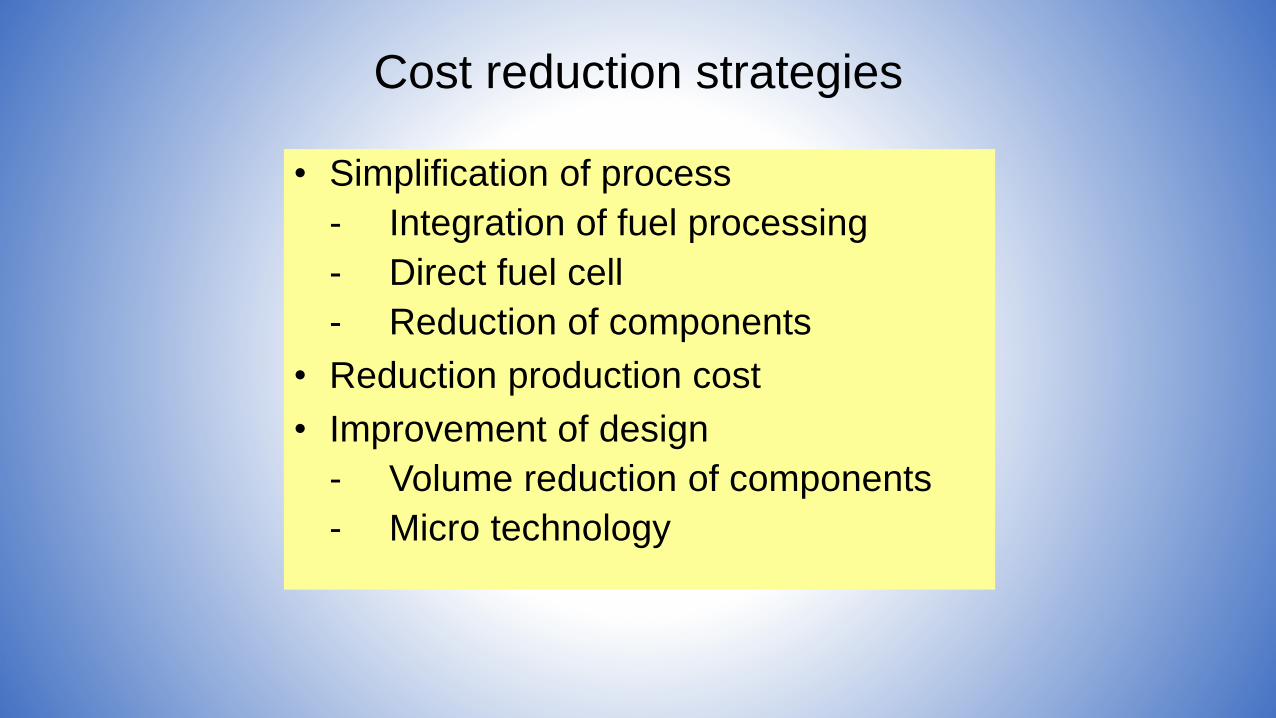
Cost reduction strategies
• Simplification of process
- Integration of fuel processing
- Direct fuel cell
- Reduction of components
• Reduction production cost
• Improvement of design
- Volume reduction of components
- Micro technology
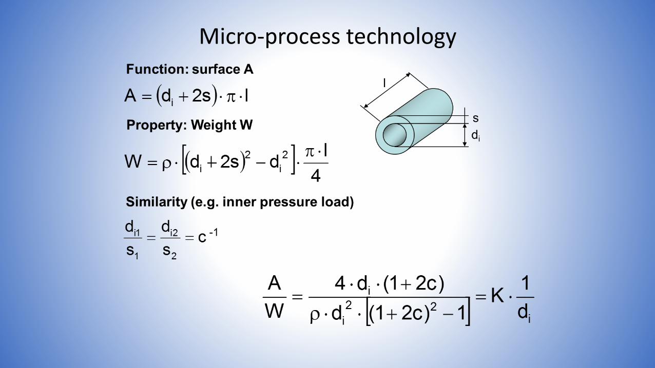
Micro-process technology
Ratio definition
Ratio = Micro solution/Macro solution
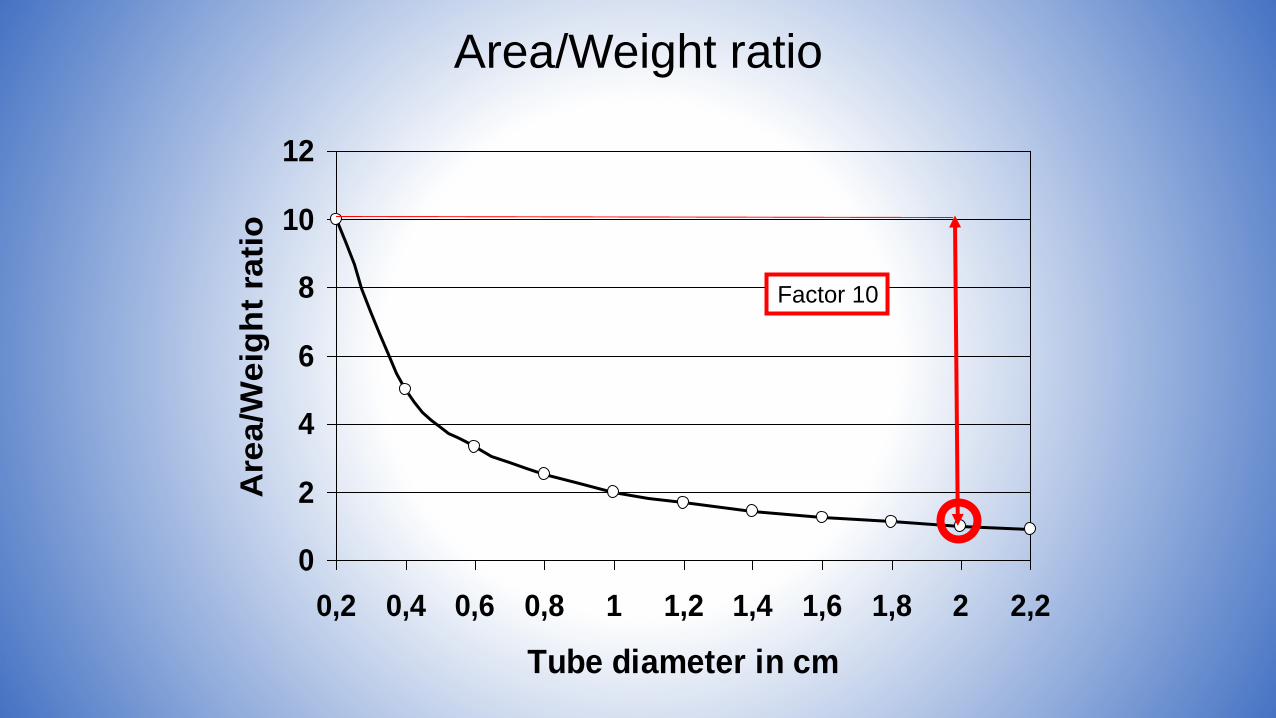
Area/Weight ratio
0
2
4
6
8
10
12
0,2 0,4 0,6 0,8 1 1,2 1,4 1,6 1,8 2 2,2
Tube diameter in cm
Are
a/W
eig
ht
rati
o
Factor 10
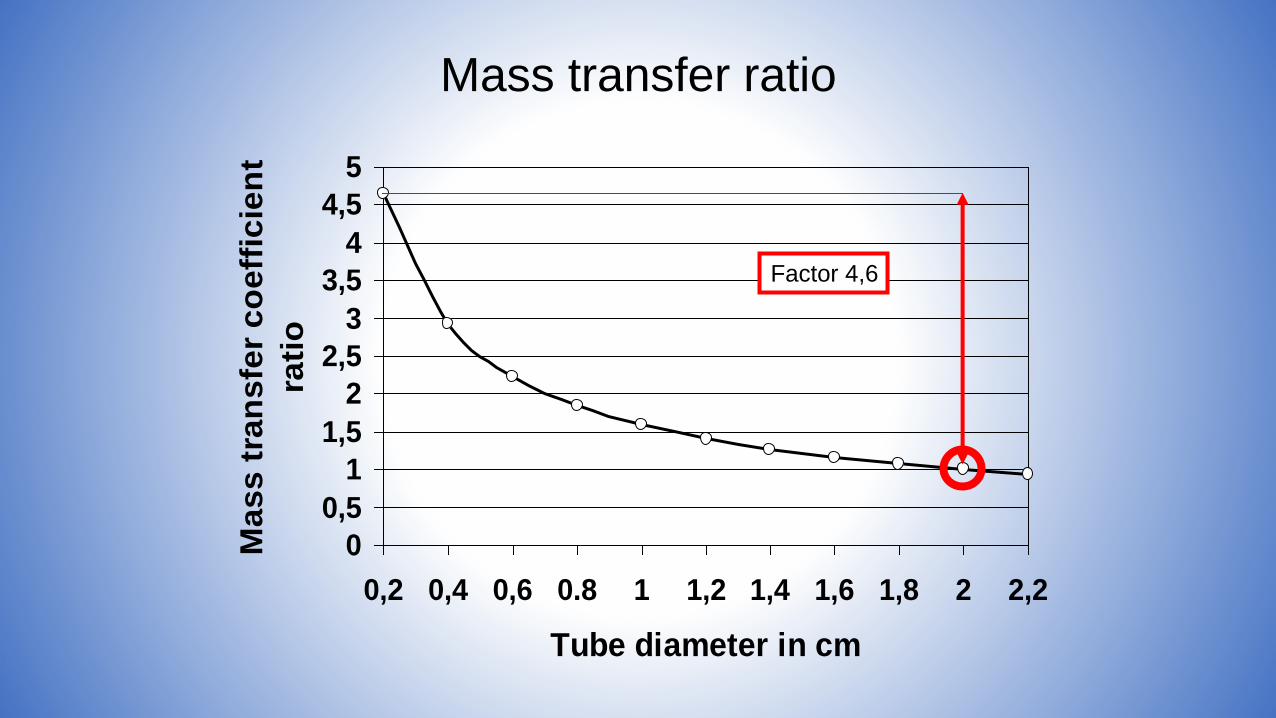
Mass transfer ratio
0
0,5
1
1,5
2
2,5
3
3,5
4
4,5
5
0,2 0,4 0,6 0.8 1 1,2 1,4 1,6 1,8 2 2,2
Tube diameter in cm
Ma
ss
tra
ns
fer
co
eff
icie
nt
rati
o
Factor 4,6
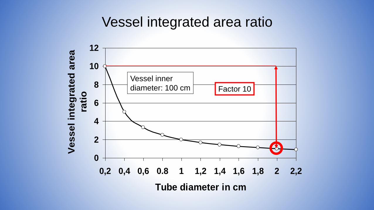
Vessel integrated area ratio
0
2
4
6
8
10
12
0,2 0,4 0,6 0.8 1 1,2 1,4 1,6 1,8 2 2,2
Tube diameter in cm
Ve
ss
el
inte
gra
ted
are
a
rati
oVessel inner
diameter: 100 cm Factor 10

Area related vessel material ratio
0
0,2
0,4
0,6
0,8
1
1,2
1,4
0,2 0,4 0,6 0.8 1 1,2 1,4 1,6 1,8 2 2,2
Tube diameter in cm
Are
a r
ela
ted
ve
ss
el
ma
teri
al
rati
o
Factor 20
Vessel inner
diameter: 100 cm
• Sustainable transportation principles
• All electric ship and system integration
• Hybrid system design
• Principles of fuel processing
• Principles of energy storage
• Engineering challenges
• Conclusion
• Fluctuating electricity for land and bio fuels for sea transport
• No principal change in naval power supply
• All-electric ship offers easy use of fuel cells and renewableharvesting system solution
• Hybridization combines fuel cells, heat engines, or/and batteries
• Hybridization allows fuel cell system efficiencies of more than 70%
• Electric storage helpful but not essential as for land transport
• Minimizing dissipation losses engineering task
• Micro technology allows clear weight and thus cost reduction forelectrochemical devices


H2 + 1/2 O2 H2O
1/2 O2
H2O
Current IElectric work
H2
2e-
1
2H+
Anode Electrolyte Cathode
2
3
O2-
Oxygen ion conduction
.e2H2H2
OHOH2 2
2
2
2 Oe2O2
1

H2 + 1/2 O2 H2O
1/2 O2
Current IElectric work
H2
2e-
1
2H+
Anode Electrolyte Cathode
2
O2-
3
H2O
Proton conduction
2
2 Oe2O2
1
OHOH2 2
2
.e2H2H2