vulnerability assessment of zebra and quagga mussels on ... · forebay to diesel fire pump room ......
TRANSCRIPT

Vulnerability Assessment of Zebra and
Quagga Mussels on Facilities from Intake
to Discharge
Tom Prescott, P. Eng.
RNT Consulting Inc.

What is a Vulnerability
Assessment?• Itemize and inspect all structures and
components that come into contact with raw water
• Make an informed judgment of the degree to which Zebra or Quagga Mussels will impair the performance of these structures and components.

Why do an assessment?
• The threat from mussels is real – only the level may vary.
• Planning/budgeting
• Insurance
• Performance commitments
• It’s the prudent thing to do.

What is a Vulnerability
Assessment Template?
• Background
• A tool to assist organizations in
performing their own assessments.
• The document contains all the
necessary steps to complete an
assessment.
• The template can be modified to suit
specific needs.

How does a Template Help?
• A structured methodology (common approach
in your organization)
• Reduced start-up time
• Helps to accurately define costs.
• Less chance to overlook or forget some items
that may be at risk

Template Benefits
• Permits multiple teams
• More control over time schedule
• Local effort reduces costs
• Subsequent reviews can be more focused
• Evolving document - will improve with
feedback

Template Structure
• 3 step process: plan, assess, follow-up.
• List of Activities in each step
• Appendices with:
– Sample plan
– Checklist for major raw water systems
– Typical facility details.

Assessment Steps
• 1 - Preparing for the Assessment
• 2 - Conducting the Assessment
• 3 - Follow up

Preparation: Planning“If you don’t know where you are going how will
you know when you get there?”- Author Unknown
Plans should be? Big (y/n) Small (y/n)
Goals / objectives
Costs
Schedule
Product

2. Preparation (Step 1)
Item o.
Item Status
Comments /
Plan to Resolve
1 Planning
1.1 Has the project scope – including definition and objectives – been prepared?
1.2 Has the Project Scope Statement been approved?
1.3 Is there a Project Plan against which to measure progress?
1.4 Does the Project Plan address the following areas:
1.4.1 Project Scope and Deliverables
1.4.2 Project Schedule
1.4.3 Project Budget
1.4.4 Project Organization and Resources
1.5 Were key project stakeholders brought into the Project Plan?
1.6 Were potential customers involved early in the planning process?
1.7 If there are vendors, have they signed off on the Project Plan?
1.8 If there is an independent oversight contractor, have they signed off on the
Project Plan?
1.9 Is the Project Sponsor function identified and defined?
1.10 Are there alternate persons if key members of the project are not available or
become reassigned?
1.11 Other organization items (please list):
2 Tracking & Monitoring
2.1 Are the various types of reports, their contents, frequency, and audience
defined and communicated to the Project Team?
2.2 Are the input requirements from Project Team members clearly documented
and communicated?
3 Meetings and Input Data
3.1 Have the various meetings, purpose, context, frequency, and participants
been defined and communicated?
3.2 Have the drawings and documents from the facility sites been requested?
4 Project Assumptions and Constraints
4.1 Are there any key assumptions upon which the assessment is based and
have these assumptions been documented?
4.2 Does the Project have any Constraints such as:
4.2.1 Facility shutdown schedules?
4.2.2 Facility access limitations and ventilation requirements?
4.2.3 Monitoring issues such as availability of reports from sampling plates set out
in previous seasons?
4.2.4 Any training needed for key project staff?
4.2.5 Any pre-project procurement needed for portable field equipment?
•[1] Enter one of the following: C (Complete), P (Partially Complete), Y (Yes), N (No); NA (Not Applicable)


Preparation: the Team
• Multi-discipline Team
– Leadership
– Biology
– Engineering and operations
– Chemistry (optional)
• Have some awareness of treatment
options

Preparation: document review
• Gather site documents
• Assess specific design features (eg where does fire protection draw water from?)
• Size of smallest diameter piping
• Materials of construction
• Duty cycle of all equipment in contact with raw water

Preparation: document review
• One checklist for each system
• Typical Systems:– Service water
– Unit Cooling water
– Domestic water
– Fire Protection
– Drainage and sumps
– Instrumentation
– Intake and discharge
• Modify checklist to suit your particular facility


SERVICE WATER
JOCKEY PUMP
TO BAY WET BAY
FIRE PUMP 1A (MOTOR)
TO BAY
FIRE PUMP 1B (DIESEL)
CIRCULATING WATER SCREENHOUSE
TO SCREENHOUSE
FOREBAY
TO DIESEL FIRE PUMP ROOM SPRINKLERS
FIRE TRUCK CONNECTION
TO FIRE LOOP
TO FIRE LOOP
Chm Injection
Shell and Mussel Transport
Rural Water
Rural Water
Rural Water
Shell and Mussel TransportClose on FP testing
Rural Water or Radiator

APPENDIX B
SYSTEM WALKTHROUGH CHECKLIST
System or Structure
Name:
Prepared by: Date of Preparation:
1. Instructions for Using this Document
Prepare one of these sheets for each system or major structure identified in the Deliverables list. For each Item No. below, complete all blank fields (see footnotes for Status and At Risk of Mussels columns).
For some of the components such as valves and strainers there may be several in one system. If more than one component needs to be considered add an extra sheet for that particular component group.
Refer to appendix C for additional information and suggestions about various systems and components.
Add additional rows as required where you identify items that need to be considered and are not covered elsewhere in the list.
2. Walkthrough Checklist
Item No.
Item Status 1
At Risk
(yes/no) Comments
1 General for Dams, Reservoirs, Aqueducts
1.1 Are there any membranes, control joints, permeable construction media, drains, etc. that will let raw water pass?
1.2 Are there any air vents?
1.3 Check if the spillway and appurtenances are always wet or dry and record duration of dry period.
1.4 How much does the water level (i.e. reservoir water surface elevation) fluctuate?
1.5 Are all potential water seepage paths inspected on a regular basis?
2 Water Intake Structures
2.1 Types of intake structures present (more than one may be present):
2.1.1 Open Canal Direct into Facility (concrete)
2.1.2 Open Canal Direct into Facility (other material-specify)
2.1.3 Forebay (specify lining material)
2.1.4 Tower (specify construction material)
2.1.5 Submerged Tunnel or pipe intake (specify construction material)
2.1.6 Penstock intakes (specify construction material)
2.1.7 Fish Barriers
1 Enter one of the following: C (Complete), P (Partially Complete), A (Absent); Y (Yes), N (No); NA (Not Applicable)

Assessment Steps
• 1 - Preparing for the Assessment
• 2 - Conducting the Assessment
• 3 - Follow up

Pre-Field trip Site Meeting

Site Walkthrough –
FOLLOW THE WATER!!


Risk to Intake Structures
• Loss of flow through settlement, initially due
to increased coefficient of friction, later due to
volume restriction
• Blockage of fixed screens such as trash racks
• Fouling of submerged structures such as
pump bells
• Shell debris collecting in low lift wells, pump
wells or forebays


Risk to Fire Protection Systems
• Main electrical / diesel pump may have fixed screen on intake which may be blocked
• Transport of shells and veligers into the system during testing.
• If system not stagnant between tests oxygen will not decline, mussels may survive
• Make-up water if used provides continuous source of oxygen and mussels if not filtered
• If no strainers are present, make-up pumps or dedicated fire pumps can introduce adult mussels or shell debris into the FP system, this in turn may plug spray nozzles.


• Sprinkler Nozzles
• Fire Hose Nozzles
• Fire Hydrants

Risk to Cooling Water Systems
• Decrease in system pipe diameter & flow due to
mussel settlement
• Plugging of heat exchangers with clumps or
individual shells; loss of cooling
• Partial plugging of heat exchangers may lead to
uneven flow velocities in the heat exchanger as well
as silt build up. These conditions could result in pipe
abrasion and erosion.
• Blockage of system valves (in open or shut position).
Fouling of valve seat can lead to improper operation.
• Blockage of building drains and fouling of sumps

Heat Exchanger plugged by shell
debris from upstream
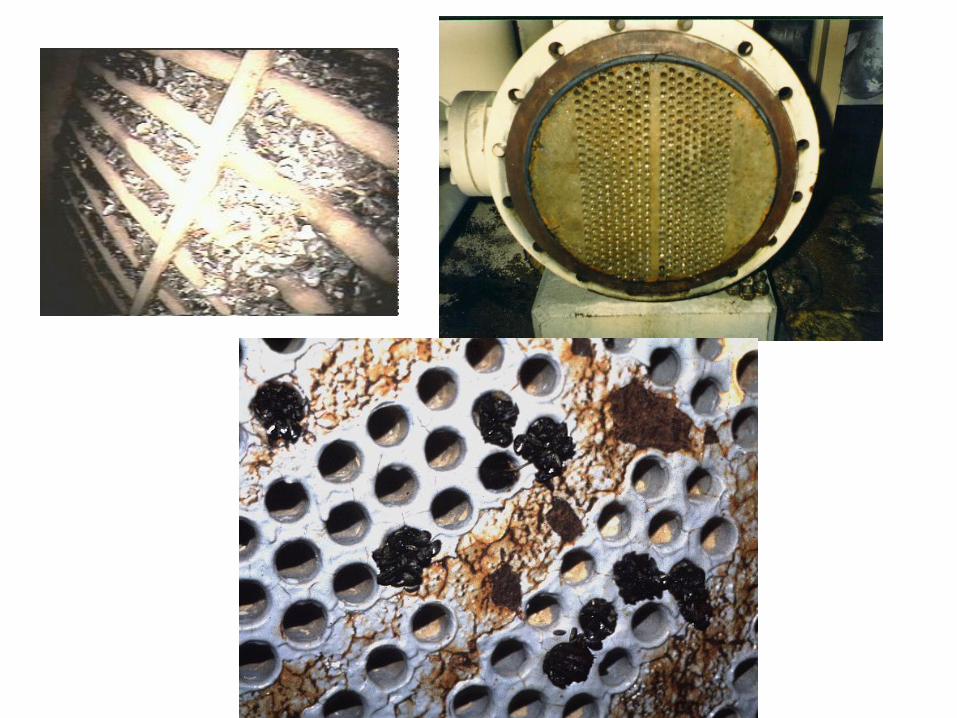


Open up Equipment


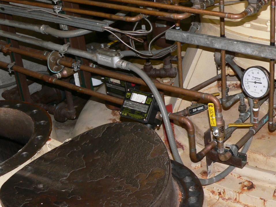
Risk to instrumentation in contact with raw water
Any instrument in contact with raw water should be
evaluated as readings could be affected

Level gauges

Follow the water to the
discharge

Step 3 - Follow up
“Even if you’re on the right track, if you just sit
there, you’ll get run over.” – Will Rogers
• Gather Data– Collect data from questions during field inspection
– Arrange for ongoing monitoring
– Conduct any tests needed
• Prepare Report– Observations, risks, conclusions &
recommendations
– Future budget requirements

Thank you
www.rntconsulting.net
http://www.usbr.gov/mussels/