vtu question paper solutions - navodaya … · vtu question paper solutions unit-1 1 ... this kind...
TRANSCRIPT
VTU QUESTION PAPER SOLUTIONS
UNIT-1
1. a. What is data communication? What are its characteristics? Explain.
Ans: [June 13/Dec 13/Dec 14]
Data communications are the exchange of data between two devices via some form of transmission
medium such as a wire cable. Four fundamental characteristics: delivery, accuracy, timeliness, and
jitter.
1. Delivery. The system must deliver data to the correct destination. Data must be received by
the intended device or user and only by that device or user.
2. Accuracy. The system must deliver the data accurately. Data that have been altered in
transmission and left uncorrected are unusable.
3. Timeliness. The system must deliver data in a timely manner. Data delivered late are useless.
In the case of video and audio, timely delivery means delivering data as they are produced, in the
same order that they are produced, and without significant delay. This kind of delivery is called real-
time transmission.
4. Jitter. Jitter refers to the variation in the packet arrival time. It is the uneven delay in the
delivery of audio or video packets. For example, let us assume that video packets are sent every 30
ms. If some of the packets arrive with 30-ms delay and others with 40-ms delay, an uneven quality
in the video is the result of transmission medium such as a wire cable. Four fundamental
characteristics: delivery, accuracy, timeliness, and jitter.
1. Delivery. The system must deliver data to the correct destination. Data must be received by
the intended device or user and only by that device or user.
2. Accuracy. The system must deliver the data accurately. Data that have been altered in
transmission and left uncorrected are unusable.
3. Timeliness. The system must deliver data in a timely manner. Data delivered late are useless.
In the case of video and audio, timely delivery means delivering data as they are produced, in the

same order that they are produced, and without significant delay. This kind of delivery is called real-
time transmission.
4. Jitter. Jitter refers to the variation in the packet arrival time. It is the uneven delay in the
delivery of audio or video packets. For example, let us assume that video packets are sent every 30
ms. If some of the packets arrive with 30-ms delay and others with 40-ms delay, an uneven quality
in the video is the result.
b. Define following terms (I) protocol (II) Internet. [June 13/Dec14]
Ans:
A protocol is a set of rules that govern data communications. A protocol defines what is
communicated, how k is communicated, and when it is communicated. The key elements of a
protocol are syntax, semantics, and timing.
The Internet today is not a simple hierarchical structure. It is made up of many wide- and localarea
networks joined by connecting devices and switching stations. It is difficult to give an accurate
representation of the Internet because it is continually changing--new networks are being added,
existing networks are adding addresses, and networks of defunct companies are being removed.
Today most end users who want Internet connection use the services of Internet service providers
(ISPs). There are international service providers, national service providers, regional service
providers, and local service providers. The Internet today is run by private companies, not the
government. The figure shows a conceptual (not geographic) view of the Internet.

c. Describe with neat diagram the functions of each layer in the OSI model
[June 13/Dec 15]
Ans:
The OSI model is a layered framework for the design of network systems that allows communication
between all types of computer systems. It consists of seven separate but related layers, each of which
defines a part of the process of moving information across a network.
Physical Layer:
The physical layer coordinates the functions required to carry a bit stream over a physical medium.
It deals with the mechanical and electrical specifications of the interface and transmission medium.
It also defines the procedures and functions that physical devices and interfaces have to

defines the type of transmission medium.
Representation of bits. The physical layer data consists of a stream of bits (sequence of 0s or
ls) with no interpretation. To be transmitted, bits must be encoded into signals - electrical or
optical. The physical layer defines the type of encoding (how 0s and 1s are changed to signals).
Data rate. The transmission rate--the number of bits sent each second--is also defined by the
physical layer. In other words, the physical layer defines the duration of a bit, which is how
long it lasts.
perform for transmission to occur
The physical layer is also concerned with the following:
Physical characteristics of interfaces and medium. The physical layer defines the
characteristi cs of the interface between the devices and the transmission medium. It also

Synchronization of bits. The sender and receiver not only must use the same bit rate but also
must be synchronized at the bit level. In other words, the sender and the receiver
every other device), a star topology (devices are connected through a central device), a ring
topology (each device is connected to the next, forming a ring), a bus topology (every device
is on a common link), or a hybrid topology (this is a combination of two or more topologies).
Transmission mode. The physical layer also defines the direction of transmission between
two devices: simplex, half-duplex, or full-duplex. In simplex mode, only one device can send;
the other can only receive. The simplex mode is a one-way communication. In the half-duplex
mode, two devices can send and receive, but not at the same time. In a fullduplex (or simply
duplex) mode, two devices can send and receive at the same time.
Data Link Layer:
The data link layer transforms the physical layer, a raw transmission facility, to a reliable link. It
makes the physical layer appear error-free to the upper layer (network layer). The figure shows the
relationship of the data link layer to the network and physical layers Responsibilities of the data link
layer include the following:
clocks must be synchronized.
Line configuration. The physical layer is concerned with the connection of devices to the
media. In a point - to - point configuration, two devices are connected
Through a dedicated link. In a multipoint conf iguration, a link is shared among several
devices.
Physical topology. The physical topology defines how devices are connected to make a
network. Devices can be connected by using a mesh topology (every device is connected to

Framing: The data link layer divides the stream of bits received from the network layer into
manageable data units called frames.
Physical addressing: If frames are to be distributed to different systems on the network, the data
link layer adds a header to the frame to define the sender and/or receiver of the frame. If the frame
is intended for a system outside the sender's network, the receiver address is the address of the device
that connects the network to the next one
Network Layer
The network layer is responsible for the source-to-destination delivery of a packet, possibly across
multiple networks (links). Whereas the data link layer oversees the delivery of the packet between
two systems on the same network (links), the network layer ensures that each packet gets from its
point of origin to its final destination
Transport Layer
The transport layer is responsible for process-to-process delivery of the entire message. A process is
an application program running on a host. Whereas the network layer oversees source-todestination
delivery of individual packets, it does not recognize any relationship between those packets. It treats
each one independently, as though each piece belonged to a separate message, whether or not it does.
The transport layer, on the other hand, ensures that the whole message arrives intact and in order,
overseeing both error control and flow control at the source-todestination level the services provided
by the first three layers (physical, data link, and network) are not sufficient for some processes. The
session layer is the network dialog controller. It establishes, maintains, and synchronizes the
interaction among communicating systems.
Presentation Layer
The presentation layer is concerned with the syntax and semantics of the information exchanged
between two systems. The figure shows the relationship between the presentation layer and the
application and session layers.
Application Layer
The application layer enables the user, whether human or software, to access the network. It provides
user interfaces and support for services such as electronic mail, remote file access and transfer, shared
database management, and other types of distributed information services.

Session Layer
The session layer provides the mechanism for opening, closing and managing a session between end-
user application processes, i.e., a semi-permanent dialogue. Communication sessions consist of
requests and responses that occur between applications. Session-layer services are commonly used
in application environments that make use of remote procedure calls (RPCs).
An example of a session-layer protocol is the OSI protocol suite session-layer protocol, also known
as X.225 or ISO 8327. In case of a connection loss this protocol may try to recover the connection.
If a connection is not used for a long period, the session-layer protocol may close it and re-open it.
It provides for either full duplex or half-duplex operation and provides synchronization points in the
stream of exchanged messages.
2. a. With neat diagram explain mesh topology and star topology with application of each.
[Dec 14] Ans:
Mesh In a mesh topology, every device has a dedicated point-to-point link to every other device. The
term dedicated means that the link carries traffic only between the two devices it connects. To find
the number of physical links in a fully connected mesh network with n node first consider that each
node must be connected to every other node. Node 1 must be connected to n-1 nodes, node 2 must
be connected to n-1 nodes, and finally node n must be connected to n-1 nodes. Need n(n-1) physical
links. If each physical link allows communication in both directions (duplex mode), we can divide
the number of links by 2. In other words, we can say that in a mesh topology, we need n(n - 1) / 2
duplex-mode links

A mesh offers several advantages over other network topologies.
1. The use of dedicated links guarantees that each connection can carry its own data load, thus
eliminating the traffic problems that can occur when links must be shared by multiple devices.
2. A mesh topology is robust. If one link becomes unusable, it does not incapacitate the entire
system.
3. There is the advantage of privacy or security. When every message travels along a dedicated
line, only the intended recipient sees it. Physical boundaries prevent other users from gaining access
to messages.
4. Point-to-point links make fault identification and fault isolation easy. Traffic can be routed
to avoid links with suspected problems. This facility enables the network manager to discover the
precise location of the fault and aids in finding its cause and solution.
The main disadvantages of a mesh are related to the amount of cabling and the number of I/O ports
required.
a. Because every device must be connected to every other device, installation and
reconnection are difficult.
b. The sheer bulk of the wiring can be greater than the available space (in walls, ceilings, or
floors) can accommodate.
c. The hardware required to connect each link (I/O ports and cable) can be prohibitively
expensive.

For these reasons a mesh topology is usually implemented in a limited fashion, for example, as a
backbone connecting the main computers of a hybrid network that can include several other
topologies.
Star Topology In a star topology, each device has a dedicated point-to-point link only to a central
controller, usually called a hub. The devices are not directly linked to one another. Unlike a mesh
topology, a star topology does not allow direct traffic between devices. The controller acts as an
exchange: If one device wants to send data to another, it sends the data to the controller, which then
relays the data to the other connected device.
Advantages:
A star topology is less expensive than a mesh topology. In a star, each device needs only one link
and one I/O port to connect it to any number of others. This factor also makes it easy to install and
reconfigure. Far less cabling needs to be housed, and additions, moves, and deletions involve only
one connection: between that device and the hub.
Other advantages include robustness. If one link fails, only that link is affected. All other links remain
active. This factor also lends itself to easy fault identification and fault isolation. As long as the hub
is working, it can be used to monitor link problems and bypass defective links.
b. What are standards? Name any four standard organizations. [Dec
13/14] Ans:
Standards are essential in creating and maintaining an open and competitive market for equipment
manufacturers and in guaranteeing national and international interoperability of data and
telecommunications technology and processes. Standards provide guidelines to manufacturers,
vendors, government agencies, and other service providers to ensure the kind of interconnectivity
necessary in today's marketplace and in international communications. Data communication
standards fall into two categories: de facto (meaning "by fact" or "by convention") and de jure
(meaning "by law" or "by regulation").
• De facto. Standards that have not been approved by an organized body but have been adopted
as standards through widespread use are de facto standards. De facto standards are often
established originally by manufacturers who seek to define the functionality of a new product
or technology.

• De jure. Those standards that have been legislated by an officially recognized body are de
jure standards.
• International Organization for Standardization (ISO). The ISO is a multinational body whose
membership is drawn mainly from the standards creation committees of various governments
throughout the world. The ISO is active in developing cooperation in the realms of scientific,
technological, and economic activity.
• International Telecommunication Elnion Telecommunication Standards Sector (ITEl-T). By
the early 1970s, a number of countries were defining national standards for
telecommunications, but there was still little international compatibility.
• American National Standards Institute (ANSI). Despite its name, the American National
Standards Institute is a completely private, nonprofit corporation not affiliated with the U.S.
federal government.
• Institute of Electrical and Electronics Engineers (IEEE). The Institute of Electrical and
Electronics Engineers is the largest professional engineering society in the world.
International in scope, it aims to advance theory, creativity, and product quality in the fields
of electrical engineering, electronics, and radio as well as in all related branches of
engineering.
• Electronic Industries Association (EIA). Aligned with ANSI, the Electronic Industries
Association is a nonprofit organization devoted to the promotion of electronics
manufacturing concerns. Its activities include public awareness education and lobbying
efforts in addition to standards development.
c. Define i) Physical layer ii) Data link layer iii)Network layer. [Dec 14/Jun
15] Ans:
Physical Layer
The physical layer coordinates the functions required to carry a bit stream over a physical medium.
It deals with the mechanical and electrical specifications of the interface and transmission medium.
It also defines the procedures and functions that physical devices and interfaces have to perform for
transmission to occur.
Data Link Layer
The data link layer transforms the physical layer, a raw transmission facility, to a reliable link. It makes
the physical layer appear error-free to the upper layer .
Network Layer
The network layer is responsible for the source-to-destination delivery of a packet, possibly across
multiple networks (links). Whereas the data link layer oversees the delivery of the packet between
two systems on the same network (links), the network layer ensures that each packet gets from its
point of origin to its final destination.
If two systems are connected to the same link, there is usually no need for a network layer. 3.
a. What is a protocol? What are its key elements? [June 14/Dec13] Ans:
In computer networks, communication occurs between entities in different systems. An entity is
anything capable of sending or receiving information. However, two entities cannot simply send bit
streams to each other and expect to be understood. For communication to occur, the entities must
agree on a protocol. A protocol is a set of rules that govern data communications. A protocol defines
what is communicated, how k is communicated, and when it is communicated. The key elements of
a protocol are syntax, semantics, and timing. i) Syntax. The term syntax refers to the structure or
format of the data, meaning the order in which they are presented. For example, a simple protocol
might expect the first 8 bits of data to be the address of the sender, the second 8 bits to be the address
of the receiver, and the rest of the stream to be the message itself. ii) Semantics. The word semantics
refers to the meaning of each section of bits. How is a particular pattern to be interpreted, and what
action is to be taken based on that interpretation iii)Timing. The term timing refers to two
characteristics: when data should be sent and how fast they can be sent. For example, if a sender
produces data at 100 Mbps but the receiver can process data at only 1

Mbps, the transmission will overload the receiver and some data will be lost
b. Differentiate between: [June 14/Dec13]
i) ARP and RARP: Address Resolution Protocol
The Address Resolution Protocol (ARP) is used to associate a logical address with a physical address.
On a typical physical network, such as a LAN, each device on a link is identified by a physical or
station address, usually imprinted on the network interface card (NIC). ARP is used to find the
physical address of the node when its Internet address is known.
Reverse Address Resolution Protocol
The Reverse Address Resolution Protocol (RARP) allows a host to discover its Internet address when
it knows only its physical address. It is used when a computer is connected to a network for the first
time or when a diskless computer is booted.
ii) ICMP and IGMP:
Internet Control Message Protocol
The Internet Control Message Protocol (ICMP) is a mechanism used by hosts and gateways to send
notification of datagram problems back to the sender. ICMP sends query and error reporting
messages.
Internet Group Message Protocol
The Internet Group Message Protocol (IGMP) is used to facilitate the simultaneous transmission of a
message to a group of recipients.
iii) UDP and TCP: User Datagram Protocol
The User Datagram Protocol (UDP) is the simpler of the two standard TCP/IP transport protocols. It
is a process-to-process protocol that adds only port addresses, checksum error control, and length
information to the data from the upper layer.
Transmission Control Protocol
The Transmission Control Protocol (TCP) provides full transport-layer services to applications. TCP
is a reliable stream transport protocol. The term stream, in this context, means connectionoriented:
A connection must be established between both ends of a transmission before either can transmit
data.

At the sending end of each transmission, TCP divides a stream of data into smaller units called
segments. Each segment includes a sequence number for reordering after receipt, together with an
acknowledgment number for the segments received. Segments are carried across the internet inside
of IP datagrams. At the receiving end, TCP collects each datagram as it comes in and reorders the
transmission based on sequence numbers.
4. a. Give the comparison between LAN, MAN and WAN with an example?
Ans: [Dec 13/June 13]
Local Area Network A local area network (LAN) is usually privately owned and links the devices in a single office,
building, or campus. Depending on the needs of an organization and the type of technology used, a
LAN can be as simple as two PCs and a printer in someone's home office; or it can extend throughout
a company and include audio and video peripherals. Currently, LAN size is limited to a few
kilometers.
LANs are designed to allow resources to be shared between personal computers or workstations. The
resources to be shared can include hardware (e.g., a printer), software (e.g., an application program),
or data. A common example of a LAN, found in many business environments, links a workgroup of
task-related computers, for example, engineering workstations or accounting PCs. One of the
computers may be given a large capacity disk drive and may become a server to clients. Software
can be stored on this central server and used as needed by the whole group.
In addition to size, LANs are distinguished from other types of networks by their transmission media
and topology. In general, a given LAN will use only one type of transmission medium. The most
common LAN topologies are bus, ring, and star.

Wide Area Network
A wide area network (WAN) provides long-distance transmission of data, image, audio, and video
information over large geographic areas that may comprise a country, a continent, or even the whole
world.
A WAN can be as complex as the backbones that connect the Internet or as simple as a dial-up line
that connects a home computer to the Internet. We normally refer to the first as a switched WAN and
to the second as a point-to-point WAN. The switched WAN connects the end systems, which usually
comprise a router (internet-working connecting device) that connects to another LAN or WAN. The
point-to-point WAN is normally a line leased from a telephone or cable TV provider that connects a
home computer or a small LAN to an Internet service provider (ISP). This type of WAN is often
used to provide Internet access.
Metropolitan Area Networks
A metropolitan area network (MAN) is a network with a size between a LAN and a WAN. It
normally covers the area inside a town or a city. It is designed for customers who need a highspeed
connectivity, normally to the Internet, and have endpoints spread over a city or part of city. A good
example of a MAN is the part of the telephone company network that can provide a highspeed DSL
line to the customer.

b. Describe with neat diagram the functions of each layer in the TCP/IP model
Ans: [Dec 13]
The TCP/IP protocol suite is made of five layers: physical, data link, network, transport, and
application. The first four layers provide physical standards, network interfaces, internetworking,
and transport functions that correspond to the first four layers of the OSI model. The three topmost
layers in the OSI model, however, are represented in TCP/IP by a single layer called the application
layer.
TCP/IP is a hierarchical protocol made up of interactive modules, each of which provides a specific
functionality; however, the modules are not necessarily interdependent. Whereas the OSI model
specifies which functions belong to each of its layers, the layers of the TCP/IP protocol suite contain
relatively independent protocols that can be mixed and matched depending on the needs of the
system. The term hierarchical means that each upper-level protocol is supported by one or more
lower-level protocols.
At the transport layer, TCP/IP defines three protocols: Transmission Control Protocol (TCP), User
Datagram Protocol (UDP), and Stream Control Transmission Protocol (SCTP). At the network layer,
the main protocol defined by TCP/IP is the Internetworking Protocol (IP); there are also some other
protocols that support data movement in this layer.
Physical and Data Link Layers
At the physical and data link layers, TCP/IP does not define any specific protocol. It supports all the
standard and proprietary protocols. A network in a TCP/IP internetwork can be a local-area network
or a wide-area network.
Network Layer
At the network layer (or, more accurately, the internetwork layer), TCP/IP supports the
Internetworking Protocol. IP, in turn, uses four supporting protocols: ARP, RARP, ICMP, and
IGMP.
Internetworking Protocol (IP)
The Internetworking Protocol (IP) is the transmission mechanism used by the TCP/IP protocols. It
is an unreliable and connectionless protocol--a best-effort delivery service. The term best effort
means that IP provides no error checking or tracking. IP assumes the unreliability of the underlying
layers and does its best to get a transmission through to its destination, but with no guarantees.
IP transports data in packets called datagrams, each of which is transported separately. Datagrams
can travel along different routes and can arrive out of sequence or be duplicated. IP does not keep
track of the routes and has no facility for reordering datagrams once they arrive at their destination.
Address Resolution Protocol
The Address Resolution Protocol (ARP) is used to associate a logical address with a physical address.
On a typical physical network, such as a LAN, each device on a link is identified by a physical or
station address, usually imprinted on the network interface card (NIC). ARP is used to find the
physical address of the node when its Internet address is known.
Reverse Address Resolution Protocol
The Reverse Address Resolution Protocol (RARP) allows a host to discover its Internet address when
it knows only its physical address. It is used when a computer is connected to a network for the first
time or when a diskless computer is booted.
Internet Control Message Protocol
The Internet Control Message Protocol (ICMP) is a mechanism used by hosts and gateways to send
notification of datagram problems back to the sender. ICMP sends query and error reporting
messages.
Internet Group Message Protocol

The Internet Group Message Protocol (IGMP) is used to facilitate the simultaneous transmission of a
message to a group of recipients.
Transport Layer
UDP and TCP are transport level protocols responsible for delivery of a message from a process
(running program) to another process. A new transport layer protocol, SCTP, has been devised to
meet the needs of some newer applications.
User Datagram Protocol
The User Datagram Protocol (UDP) is the simpler of the two standard TCP/IP transport protocols. It
is a process-to-process protocol that adds only port addresses, checksum error control, and length
information to the data from the upper layer.
Transmission Control Protocol
The Transmission Control Protocol (TCP) provides full transport-layer services to applications. TCP
is a reliable stream transport protocol. The term stream, in this context, means connectionoriented:
A connection must be established between both ends of a transmission before either can transmit
data.
At the sending end of each transmission, TCP divides a stream of data into smaller units called
segments. Each segment includes a sequence number for reordering after receipt, together with an
acknowledgment number for the segments received. Segments are carried across the internet inside
of IP datagrams. At the receiving end, TCP collects each datagram as it comes in and reorders the
transmission based on sequence numbers.
Stream Control Transmission Protocol
The Stream Control Transmission Protocol (SCTP) provides support for newer applications such as
voice over the Internet. It is a transport layer protocol that combines the best features of UDP and
TCP. Application Layer
The application layer in TCP/IP is equivalent to the combined session, presentation, and application
layers in the OSI model. Many protocols are defined at this layer.

5.a. What are the components of data communication system? Explain in Breif. [Dec 15]
A data communications system has five components:
1. Message. The message is the information (data) to be communicated. Popular forms of information include text, numbers, pictures, audio, and video. 2. Sender. The sender is the device that sends the data message. It can be a computer, workstation, telephone handset, video camera, and so on. 3. Receiver. The receiver is the device that receives the message. It can be a computer, workstation, telephone handset, television, and so on. 4. Transmission medium. The transmission medium is the physical path by which a message travels from sender to receiver. Some examples of transmission media include twisted-pair wire, coaxial cable, fiber-optic cable, and radio waves. 5.Protocol. A protocol is a set of rules that govern data communications. It represents an agreement between the communicating devices. Without a protocol, two devices may be connected but not communicating.
b. What is the difference between physical and logical address? Explain with an example.
[Dec 15]
Physical addressing. If frames are to be distributed to different systems on the network, the data link layer adds a header to the frame to define the sender and/or receiver of the frame. If the frame is intended for a system outside the sender's network, the receiver address is the address of the device that connects the network to the next one.
Logical addressing. The physical addressing implemented by the data link layer handles the addressing problem locally. If a packet passes the network boundary, we need another addressing system to help distinguish the source and destination systems. The network layer adds a header to the packet coming from the upper layer that, among other things, includes the logical addresses of the sender and receiver.

UNIT-2
1.a. Calculate the Shannon channel capacity in the following cases: [June 13]
(i) Bandwidth =20Khz SNRdb=40 (ii) Bandwidth =200 kHz SNRdb=6
Ans: Bandwidth=20khz
SNR=40db
Capacity= bandwidth*log (1+SNR)
= 20*10³* log(1+20)
=87846.34bps
Bandwidth=200khz SNR=6
Capacity=561,471bps
b. A file contains 3 million bytes. How long does it take to download this file using
100kbps [June 13/Dec 14]
Ans:2 b a file contains 3,000,000 bytes
3,000,000*8
24,000,000 bits
Capacity of the channel 100kbps
Time required is 24000000/100000
=240
c. Define line coding. Describe Unipolar NRZ, polar NRZ-L, Bipolar AMI and
Manchester encoding with the information sequence 101011100 [June 13/Dec
14/Dec 15]
Ans:
Line coding is the process of converting digital data to digital signals NRZ (Non- Return-to-Zero)
Traditionally, a unipolar scheme was designed as a non-return-to-zero (NRZ) scheme in which the
positive voltage defines bit I and the zero voltage defines bit O. It is called NRZ because the signal
does not return to zero at the middle of the bit. Figure show a unipolar NRZ scheme.
Compared with its polar counterpart this scheme is very costly. The normalized power is double that
for polar NRZ. For this reason, this scheme is normally not used in data communications today

Non-Return-to-Zero (NRZ) In polar NRZ encoding, we use two levels of voltage amplitude. We can
have two versions of polar NRZ: NRZ-Land NRZ-I, as shown in Figure. The figure also shows the
value of r, the average baud rate, and the bandwidth. In the first variation, NRZ-L (NRZ-Level), the
level of the voltage determines the value of the bit. In the second variation, NRZ-I (NRZ-Invert), the
change or lack of change in the level of the voltage determines the value of the bit. If there is no
change, the bit is 0; if there is a change, the bit is 1.
2. a. Explain three causes for transmission impairments. [Dec 14]
Ans: Three causes of impairment are attenuation, distortion, and noise
Attenuation
Attenuation means a loss of energy. When a signal, simple or composite, travels through a medium,
it loses some of its energy in overcoming the resistance of the medium. That is why a wire carrying
electric signals gets warm, if not hot, after a while. Some of the electrical energy in the signal is
converted to heat. To compensate for this loss, amplifiers are used to amplify the signal.
Decibel
To show that a signal has lost or gained strength, engineers use the unit of the decibel. The decibel
(dB) measures the relative strengths of two signals or one signal at two different points. Note that
the decibel is negative if a signal is attenuated and positive if a signal is amplified.
Variables P1 and P2 are the powers of a signal at points 1 and 2, respectively.
Distortion
Distortion means that the signal changes its form or shape. Distortion can occur in a composite signal
made of different frequencies. Each signal component has its own propagation speed (see the next
section) through a medium and, therefore, its own delay in arriving at the final destination.
Differences in delay may create a difference in phase if the delay is not exactly the same as the period
duration.
Noise
Noise is another cause of impairment. Several types of noise, such as thermal noise, induced noise,
crosstalk, and impulse noise, may corrupt the signal. Thermal noise is the random motion of electrons
in a wire which creates an extra signal not originally sent by the transmitter. Induced noise comes
from sources such as motors and appliances.
b. Describe with neat wave form any two polar coding schemes [Dec 14/June 13]
Ans:
Polar Schemes
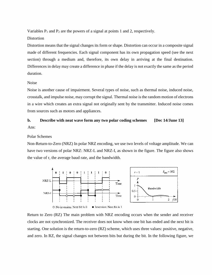
Non-Return-to-Zero (NRZ) In polar NRZ encoding, we use two levels of voltage amplitude. We can
have two versions of polar NRZ: NRZ-L and NRZ-I, as shown in the figure. The figure also shows
the value of r, the average baud rate, and the bandwidth.
Return to Zero (RZ) The main problem with NRZ encoding occurs when the sender and receiver
clocks are not synchronized. The receiver does not know when one bit has ended and the next bit is
starting. One solution is the return-to-zero (RZ) scheme, which uses three values: positive, negative,
and zero. In RZ, the signal changes not between bits but during the bit. In the following figure, we

see that the signal goes to 0 in the middle of each bit. It remains there until the beginning of the next
bit.
c. Give data rate formula suggested by Nyquist and Shannon Low pass
communication has BW of 1MHZ. What is Shannon capacity of channel if SNR is
40db?. What bit rate is
attainable using 8-level pilses? [Dec 14/Dec 13] Ans:
Nyquist Bit Rate
Bit Rate = 2 x bandwidth x Log L
Shannon Capacity
Capacity = bandwidth x Log2 (1 + SNR)
Bandwidth = 1 MHz SNR=40db
bit rate = 2 x bandwidth x Log2L
= 2 x 10⁶ x Log28 = 6
mbps
3. a. Explain briefly, with neat figures, the two approaches for digital transmission.
Ans : [Dec 14/Dec 15]
The transmission of binary data across a link can be accomplished in either parallel or serial mode.
In parallel mode, multiple bits are sent with each clock tick. In serial mode, 1 bit is sent with each
clock tick. While there is only one way to send parallel data, there are three subclasses of serial
transmission: asynchronous, synchronous, and isochronous.

PARALLEL TRANSMISSION
Binary data, consisting of ls and Os, may be organized into groups of n bits each. Computers produce
and consume data in groups of bits. By grouping, we can send data n bits at a time instead of 1. This
is called parallel transmission.
The mechanism for parallel transmission is a conceptually simple one: Use n wires to send n bits at
one time. That way each bit has its own wire, and all n bits of one group can be transmitted with each
clock tick from one device to another. The following figure shows how parallel transmission works
for n = 8. Typically, the eight wires are bundled in a cable with a connector at each end.
The advantage of parallel transmission is speed. All else being equal, parallel transmission can
increase the transfer speed by a factor of n over serial transmission. But there is a significant
disadvantage: cost. Parallel transmission requires n communication lines just to transmit the data
stream. Because this is expensive, parallel transmission is usually limited to short distances.
SERIAL TRANSMISSION
In serial transmission one bit follows another, so we need only one communication channel rather than
n to transmit data between two communicating devices.
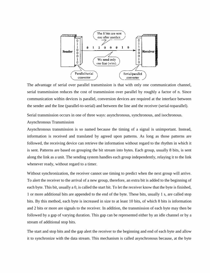
The advantage of serial over parallel transmission is that with only one communication channel,
serial transmission reduces the cost of transmission over parallel by roughly a factor of n. Since
communication within devices is parallel, conversion devices are required at the interface between
the sender and the line (parallel-to-serial) and between the line and the receiver (serial-toparallel).
Serial transmission occurs in one of three ways: asynchronous, synchronous, and isochronous.
Asynchronous Transmission
Asynchronous transmission is so named because the timing of a signal is unimportant. Instead,
information is received and translated by agreed upon patterns. As long as those patterns are
followed, the receiving device can retrieve the information without regard to the rhythm in which it
is sent. Patterns are based on grouping the bit stream into bytes. Each group, usually 8 bits, is sent
along the link as a unit. The sending system handles each group independently, relaying it to the link
whenever ready, without regard to a timer.
Without synchronization, the receiver cannot use timing to predict when the next group will arrive.
To alert the receiver to the arrival of a new group, therefore, an extra bit is added to the beginning of
each byte. This bit, usually a 0, is called the start bit. To let the receiver know that the byte is finished,
1 or more additional bits are appended to the end of the byte. These bits, usually 1 s, are called stop
bits. By this method, each byte is increased in size to at least 10 bits, of which 8 bits is information
and 2 bits or more are signals to the receiver. In addition, the transmission of each byte may then be
followed by a gap of varying duration. This gap can be represented either by an idle channel or by a
stream of additional stop bits.
The start and stop bits and the gap alert the receiver to the beginning and end of each byte and allow
it to synchronize with the data stream. This mechanism is called asynchronous because, at the byte

level, the sender and receiver do not have to be synchronized. But within each byte, the receiver must
still be synchronized with the incoming bit stream. That is, some synchronization is required, but
only for the duration of a single byte. The receiving device resynchronizes at the onset of each new
byte. When the receiver detects a start bit, it sets a timer and begins counting bits as they come in.
After n bits, the receiver looks for a stop bit. As soon as it detects the stop bit, it waits until it detects
the next start bit.
The figure is a schematic illustration of asynchronous transmission. In this example, the start bits are
0s, the stop bits are ls, and the gap is represented by an idle line rather than by additional stop bits.
The addition of stop and start bits and the insertion of gaps into the bit stream make asynchronous
transmission slower than forms of transmission that can operate without the addition of control
information. But it is cheap and effective, two advantages that make it an attractive choice for
situations such as low-speed communication.
Synchronous Transmission
In synchronous transmission, the bit stream is combined into longer "frames," which may contain
multiple bytes. Each byte, however, is introduced onto the transmission link without a gap between
it and the next one. It is left to the receiver to separate the bit stream into bytes for decoding purposes.
In other words, data are transmitted as an unbroken string of 1 s and 0s, and the receiver separates
that string into the bytes, or characters, it needs to reconstruct the information.
The figure gives a schematic illustration of synchronous transmission. The sender puts its data onto
the line as one long string. If the sender wishes to send data in separate bursts, the gaps between

bursts must be filled with a special sequence of 0s and ls that means idle. The receiver counts the
bits as they arrive and groups them in 8-bit units.
Without gaps and start and stop bits, there is no built-in mechanism to help the receiving device
adjust its bit synchronization midstream. Timing becomes very important, therefore, because the
accuracy of the received information is completely dependent on the ability of the receiving device
to keep an accurate count of the bits as they come in.
The advantage of synchronous transmission is speed. With no extra bits or gaps to introduce at the
sending end and remove at the receiving end, and, by extension, with fewer bits to move across the
link, synchronous transmission is faster than asynchronous transmission. For this reason, it is more
useful for high-speed applications such as the transmission of data from one computer to another.
Isochronous
In real-time audio and video, in which uneven delays between frames are not acceptable,
synchronous transmission fails. For example, TV images are broadcast at the rate of 30 images per
second; they must be viewed at the same rate. If each image is sent by using one or more flames,
there should be no delays between frames. For this type of application, synchronization between
characters is not enough; the entire stream of bits must be synchronized. The isochronous
transmission guarantees that the data arrive at a fixed rate.
b. Discuss 8B/10B coding style [Dec 14]
Ans:8B/10B
The eight binary/ten binary (8B/10B) encoding is similar to 4B/5B encoding except that a group of
8 bits of data is now substituted by a 10-bit code. It provides greater error detection capability than
4B/5B. The 8B/10B block coding is actually a combination of 5B/6B and 3B/4B encoding, as shown
in the figure.

The most five significant bits of a 10-bit block is fed into the 5B/6B encoder; the least 3 significant
bits is fed into a 3B/4B encoder. The split is done to simplify the mapping table. To prevent a long
run of consecutive 0s or ls, the code uses a disparity controller which keeps track of excess 0s over
ls (or ls over 0s). If the bits in the current block create a disparity that contributes to the previous
disparity (either direction), then each bit in the code is complemented (a 0 is changed to a 1 and a 1
is changed to a 0). The coding has 210 - 28 = 768 redundant groups that can be used for disparity
checking and error detection. In general, the technique is superior to 4B/5B because of better built-
in error-checking capability and better synchronization.
c. Explain the delta modulation. [Dec 14]
Ans:
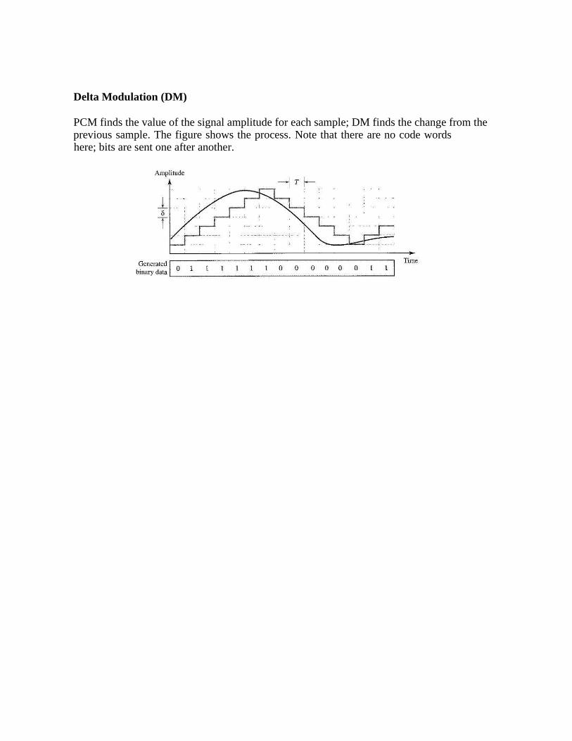
Delta Modulation (DM)
PCM finds the value of the signal amplitude for each sample; DM finds the change from the previous
sample. The figure shows the process. Note that there are no code words here; bits are sent one after
another.
Modulator
The modulator is used at the sender site to create a stream of bits from an analog signal. The process
records the small positive or negative changes, called delta δ. If the delta is positive, the process
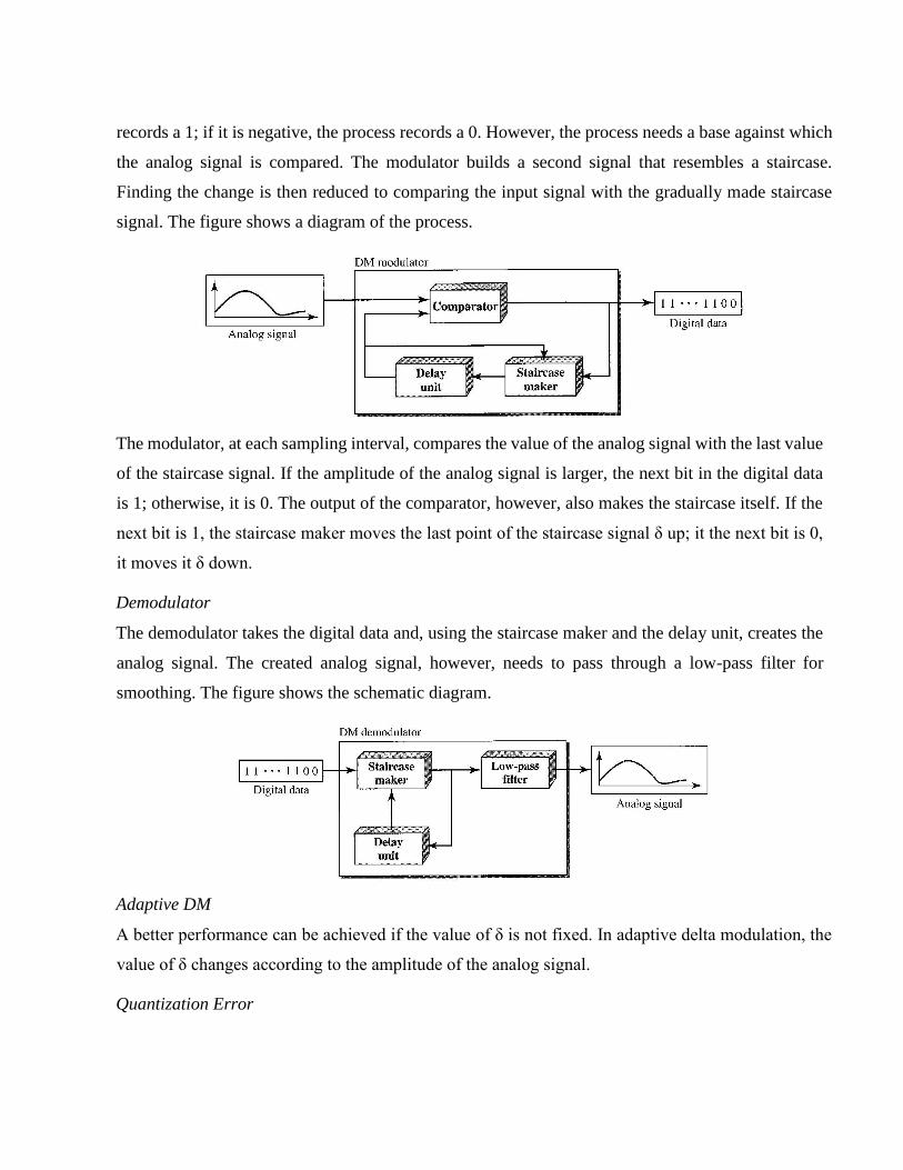
records a 1; if it is negative, the process records a 0. However, the process needs a base against which
the analog signal is compared. The modulator builds a second signal that resembles a staircase.
Finding the change is then reduced to comparing the input signal with the gradually made staircase
signal. The figure shows a diagram of the process.
The modulator, at each sampling interval, compares the value of the analog signal with the last value
of the staircase signal. If the amplitude of the analog signal is larger, the next bit in the digital data
is 1; otherwise, it is 0. The output of the comparator, however, also makes the staircase itself. If the
next bit is 1, the staircase maker moves the last point of the staircase signal δ up; it the next bit is 0,
it moves it δ down.
Demodulator
The demodulator takes the digital data and, using the staircase maker and the delay unit, creates the
analog signal. The created analog signal, however, needs to pass through a low-pass filter for
smoothing. The figure shows the schematic diagram.
Adaptive DM
A better performance can be achieved if the value of δ is not fixed. In adaptive delta modulation, the
value of δ changes according to the amplitude of the analog signal.
Quantization Error

Quantization error is always introduced in the process. The quantization error of DM, however, is
much less than that for PCM.
4. Explain the following: [Dec 13]
a. Bandwidth b. Throughput c. Error rate d. Latency e.Jitter Ans:
Bandwidth commonly measured in bits/second is the maximum rate that information can be
transferred
Throughput the actual rate that information is transferred
Error rate the number of corrupted bits expressed as a percentage or fraction of the total sent
Latency the delay between the sender and the receiver decoding it, this is mainly a function of the
signals travel time, and processing time at any nodes the information traverses
Jitter variation in the time of arrival at the receiver of the information
5. a Compare and contrast PCM and DM [June 15]
Pulse Code Modulation (PCM)
The most common technique to change an analog signal to digital data
(digitization) is called pulse code modulation (PCM). A PCM encoder has three processes, as shown in the figure.
1. The analog signal is sampled.
2. The sampled signal is quantized.
3. The quantized values are encoded as streams of bits.
Delta Modulation (DM)
PCM finds the value of the signal amplitude for each sample; DM finds the change from the previous sample. The figure shows the process. Note that there are no code words here; bits are sent one after another.
UNIT-3
1. a. Define synchronous TDM [Dec 14]
Ans:
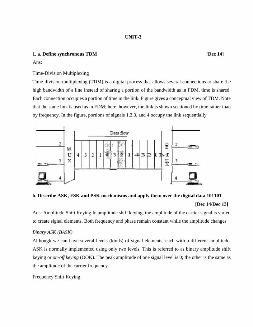
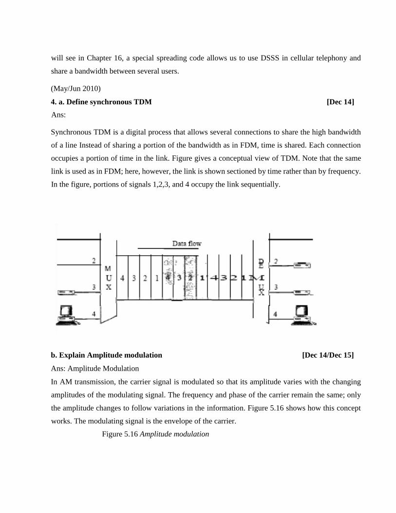
Time-Division Multiplexing
Time-division multiplexing (TDM) is a digital process that allows several connections to share the
high bandwidth of a line Instead of sharing a portion of the bandwidth as in FDM, time is shared.
Each connection occupies a portion of time in the link. Figure gives a conceptual view of TDM. Note
that the same link is used as in FDM; here, however, the link is shown sectioned by time rather than
by frequency. In the figure, portions of signals 1,2,3, and 4 occupy the link sequentially
b. Describe ASK, FSK and PSK mechanisms and apply them over the digital data 101101
[Dec 14/Dec 13]
Ans: Amplitude Shift Keying In amplitude shift keying, the amplitude of the carrier signal is varied
to create signal elements. Both frequency and phase remain constant while the amplitude changes
Binary ASK (BASK)
Although we can have several levels (kinds) of signal elements, each with a different amplitude,
ASK is normally implemented using only two levels. This is referred to as binary amplitude shift
keying or on-off keying (OOK). The peak amplitude of one signal level is 0; the other is the same as
the amplitude of the carrier frequency.
Frequency Shift Keying

In frequency shift keying, the frequency of the carrier signal is varied to represent data. The
frequency of the modulated signal is constant for the duration of one signal element, but changes for
the next signal element if the data element changes. Both peak amplitude and phase remain constant
for all signal elements. In phase shift keying, the phase of the carrier is varied to represent two or
more different signal elements. Both peak amplitude and frequency remain constant as the phase
changes. Today, PSK is more common than ASK or FSK. However, we will see Sh0l1ly that QAM,
which combines ASK and PSK, is the dominant method of digitalto- analog modulation.
2. a. With neat waveform, explain three methods of digital to analog conversion. Draw
waveform with input data 110100. [June 14]
Ans:
I. Amplitude Shift Keying
In amplitude shift keying, the amplitude of the carrier signal is varied to create signal elements.
Both frequency and phase remain constant while the amplitude changes.
II.Binary ASK (BASK)
ASK is normally implemented using only two levels. This is referred to as binary amplitude shift
keying or on-off keying (OOK). The peak amplitude of one signal level is 0; the other is the same as
the amplitude of the carrier frequency. Figure 5.3gives a conceptual view of binary ASK
Figure 5.3 Binaryy amplitude shift
keying
2.Bandwidth for ASK
Figure 5.3 also shows the bandwidth for ASK.
As we expect, the bandwidth is proportional to the signal rate (baud rate). However, there is normally
another factor involved, called d, which depends on the modulation and filtering process. The value
of d is between 0 and 1. This means that the bandwidth can be expressed as shown, where S is the
signal rate and the B is the bandwidth.
B =(1 +d) x S
The formula shows that the required bandwidth has a minimum value of 5 and a maximum value of
25. The most important point here is the location of the bandwidth. The middle of the bandwidth is
where fc the carrier frequency, is located.
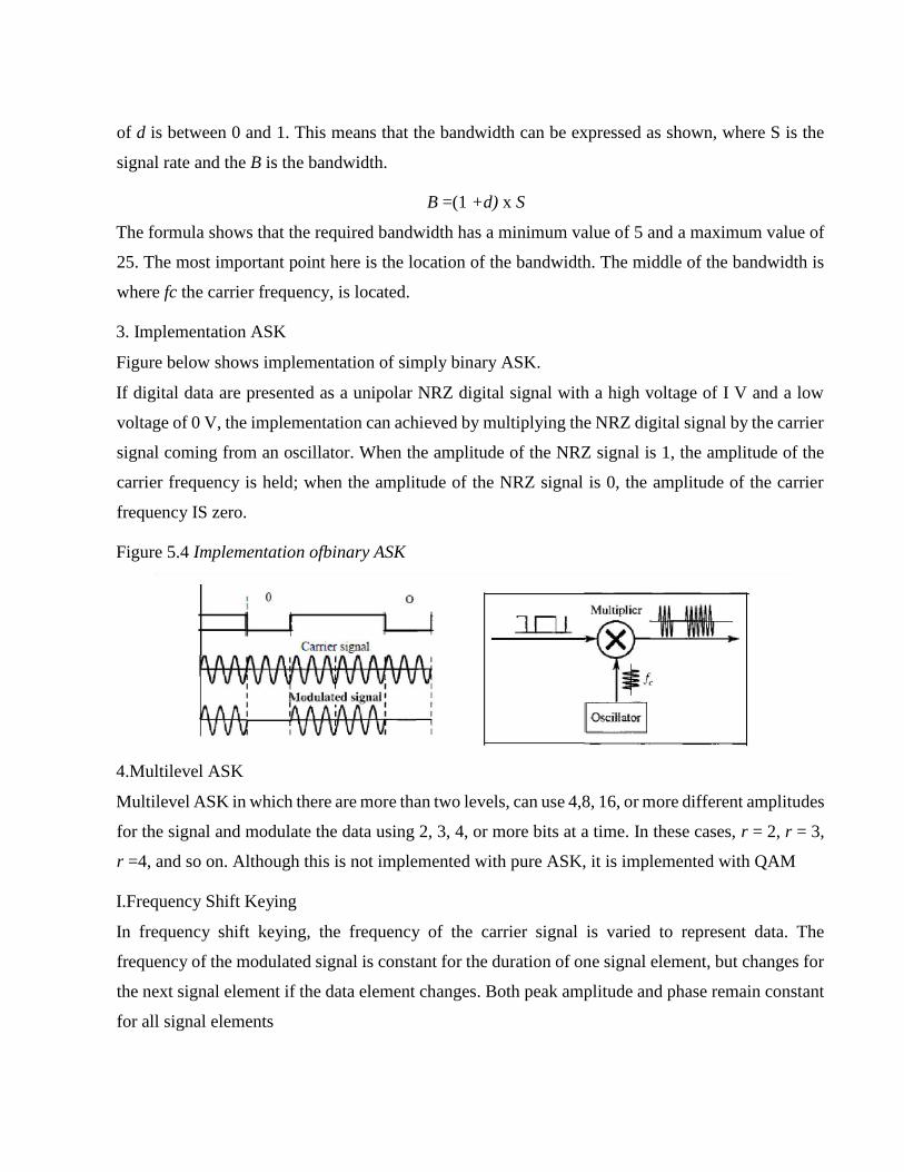
3. Implementation ASK
Figure below shows implementation of simply binary ASK.
If digital data are presented as a unipolar NRZ digital signal with a high voltage of I V and a low
voltage of 0 V, the implementation can achieved by multiplying the NRZ digital signal by the carrier
signal coming from an oscillator. When the amplitude of the NRZ signal is 1, the amplitude of the
carrier frequency is held; when the amplitude of the NRZ signal is 0, the amplitude of the carrier
frequency IS zero.
Figure 5.4 Implementation ofbinary ASK
4.Multilevel ASK
Multilevel ASK in which there are more than two levels, can use 4,8, 16, or more different amplitudes
for the signal and modulate the data using 2, 3, 4, or more bits at a time. In these cases, r = 2, r = 3,
r =4, and so on. Although this is not implemented with pure ASK, it is implemented with QAM
I.Frequency Shift Keying
In frequency shift keying, the frequency of the carrier signal is varied to represent data. The
frequency of the modulated signal is constant for the duration of one signal element, but changes for
the next signal element if the data element changes. Both peak amplitude and phase remain constant
for all signal elements

1.Binary FSK (BFSK)
One way to think about binary FSK (or BFSK) is to consider two carrier frequencies. In Figure 5.6,
we have selected two carrier frequencies,f1 andf2. First carrier frequencies,f1 if the data element is
0; the second if the data element is 1.
Figure 5.6 Binary frequency shift keying
As Figure 5.6 shows, the middle of one bandwidth isf1 and the middle of the other is f2 . Both f1 and
f2 are ∆f apart from the midpoint between the two bands. The difference between the two frequencies
is 2∆f Bandwidth for BFSK.
2.Bandwidth of FSK
Figure 5.6 also shows the bandwidth of FSK. Again the carrier signals are only simple sine waves, but
the modulation creates a non periodic composite signal with continuous frequencies.
FSK can think of as two ASK signals, each with its own carrier frequency (f1 and f2). If the difference
between the two frequencies is 2∆f, then the required bandwidth is
B=(1+d)xS+2∆f
Phase Shift Keying
In phase shift keying, the phase of the carrier is varied to represent two or more different signal
elements. Both peak amplitude and frequency remain constant as the phase changes. Today, PSK is
more common than ASK or FSK. However, we will see that QAM, which combines ASK and PSK,
is the dominant method of digitalto- analog modulation.
Binary PSK (BPSK)
The simplest PSK is binary PSK, in which we have only two signal elements, one with a phase of
0°, and the other with a phase of 180°. Figure 5.9 gives a conceptual view of PSK. Binary PSK is as
simple as binary ASK with one big advantage-it is less

susceptible to noise. In ASK, the criterion for bit detection is the amplitude of the signal; in PSK, it
is the phase. Noise can change the amplitude easier than it can change the phase. In other words,
PSK is less susceptible to noise than ASK. PSK is superior to FSK because we do not need two
carrier signals. Bandwidth Figure 5.9 also shows the bandwidth for BPSK. The bandwidth is the
same as that for binary ASK, but less than that for BFSK. No bandwidth is wasted for separating two
carrier signals.
b. What is multiplexing? With neat diagram explain FDM. [June 14]
Ans:
Whenever the bandwidth of a medium linking two devices is greater than the bandwidth needs of
the devices, the link can be shared. Multiplexing is the set of techniques that allows the simultaneous
transmission of multiple signals across a single data link.
As data and telecommunications use increases, so does traffic. We can accommodate this increase
by continuing to add individual links each time a new channel is needed, or we can install
higherbandwidth links and use each to carry multiple signals.
In a multiplexed system, n lines share the bandwidth of one link. Shows the basic format of a
multiplexed system. The lines on the left direct their transmission streams to a multiplexer (MUX),
which combines them into a single stream (many-toone). At the receiving end, that stream is fed into
a demultiplexer (DEMUX), which separates the stream back into its component transmissions (one-
to-many) and directs them to their corresponding lines. In the figure, the word link refers to the
physical path.
Frequency-Division Multiplexing
Frequency-division multiplexing (FDM) is an analog technique that can be applied when the
bandwidth of a link (in hertz) is greater than the combined bandwidths of the signals to be

transmitted. In FOM, signals generated by each sending device modulate different carrier
frequencies. These modulated signals are then combined into a single composite signal that can be
transported by the link. Carrier frequencies are separated by sufficient bandwidth to accommodate
the modulated signal. These bandwidth ranges are the channels through which the various signals
travel. Channels can be separated by strips of unused bandwidth-guard bands-to prevent signals from
overlapping. In addition, carrier frequencies must not interfere with the original data frequencies.
Figure gives a conceptual view of FDM. In this illustration, the transmission path is divided into three
parts, each representing a channel that carries one transmission.
c. What is TDM? Four sources create 250 characters per second. The frame contains one
character from each source and one extra bit for synchronization. Find i)The data rate of each
source ii) Duration of each character in each source iii) The frame rate iv) Duration of output
frame v) Frame size in bits vi) Data rate of link.
Ans: [June 13/Dec 14]
TDM
Time-division multiplexing (TDM) is a digital process that allows several connections to share the
high bandwidth of a line Instead of sharing a portion of the bandwidth as in FDM, time is shared.
Each connection occupies a portion of time in the link.
Figure gives a conceptual view of TDM. Note that the same link is used as in FDM; here, however,
the link is shown sectioned by time rather than by frequency. In the figure, portions of signals 1,2,3,
and 4 occupy the link sequentially.
Solution:
a. The data rate of each source is 250 x 8 = 2000 bps = 2 kbps.
b. Each source sends 250 characters per second; therefore, the duration of a character is 1/250 s, or4
ms.

c. Each frame has one character from each source, which means the link needs to send
250 frames per second to keep the transmission rate of each source.
d. The duration of each frame is 11250 s, or 4 ms. Note that the duration of each frame is the same as
the duration of each character coming from each source.
e. Each frame carries 4 characters and I extra synchronizing bit. This means that each frame is 4 x
8 + 1 =33 bits
f. The link sends 250 frames per second, and each frame contains 33 bits. This means that the data
rate of the link is 250 x 33, or 8250 bps. Note that the bit rate of the link is greater than the combined
bit rates of the four channels. If we add the bit rates of four channels, we get 8000 bps. Because 250
frames are traveling per second and each contains 1 extra bit for synchronizing, we need to add 250
to the sum to get 8250 bps.
3. a. What is FDM? Briefly explain its multiplexing and demultiplexing process.
Ans: [June 13]
Frequency-Division Multiplexing
Frequency-division multiplexing (FDM) is an analog technique that can be applied when the
bandwidth of a link (in hertz) is greater than the combined bandwidths of the signals to be
transmitted. In FOM, signals generated by each sending device modulate different carrier
frequencies. These modulated signals are then combined into a single composite signal that can be
transported by the link. Carrier frequencies are separated by sufficient bandwidth to accommodate
the modulated signal. These bandwidth ranges are the channels through which the various signals
travel. Channels can be separated by strips of unused bandwidth-guard bands-to prevent signals from
overlapping. In addition, carrier frequencies must not interfere with the original data frequencies.
Figure 6.3 gives a conceptual view of FDM. In this illustration, the transmission path is divided into
three parts, each representing a channel that carries one transmission. Figure 6.3 Frequency-division
multiplexing

We consider FDM to be an analog multiplexing technique; however, this does not mean that FDM
cannot be used to combine sources sending digital signals. A digital signal can be converted to an
analog signal before FDM is used to multiplex
them.
Multiplexing Process
Figure 6.4 is a conceptual illustration of the multiplexing process. Each source generates a signal of
a similar frequency range. Inside the multiplexer, these similar signals modulates different carrier
frequencies (/1,12, and h). The resulting modulated signals are then combined into a single composite
signal that is sent out over a media link that has enough bandwidth to accommodate it. Figure 6.4
FDM process
Demultiplexing Process
The demultiplexer uses a series of filters to decompose the multiplexed signal into its constituent
component signals. The individual signals are then passed to a demodulator that separates them from
their carriers and passes them to the output lines. Figure 6.5 is a conceptual illustration of
demultiplexing process.

Figure6.5
The Analog Carrier System
To maximize the efficiency of their infrastructure, telephone companies have traditionally
multiplexed signals from lower-bandwidth lines onto higher-bandwidth lines. In this way, many
switched or leased lines can be combined into fewer but bigger channels. For analog lines, FDM is
used. One of these hierarchical systems used by AT&T is made up of groups, super groups, master
groups, and jumbo groups
In this analog hierarchy, 12 voice channels are multiplexed onto a higher-bandwidth line to create a
group. A group has 48 kHz of bandwidth and supports 12 voice channels. At the next level, up to
five groups can be multiplexed to create a composite signal called a supergroup. A supergroup has a
bandwidth of 240 kHz and supports up to 60 voice channels. Supergroups can be made up of either
five groups or 60 independent voice channels. At the next level, 10 supergroups are multiplexed to
create a master group. A master group must have 2.40 MHz of bandwidth, but the need for guard
bands between the supergroups increases the necessary bandwidth to 2.52 MHz. Master groups
support up to 600 voice channels. Finally, six master groups can be combined into a jumbo group.
A jumbo group must have 15.12 MHz (6 x 2.52 MHz) but is augmented to 16.984 MHz to allow for
guard bands between the master groups.
b. Explain briefly the two spread spectrum techniques [June 13]
Ans
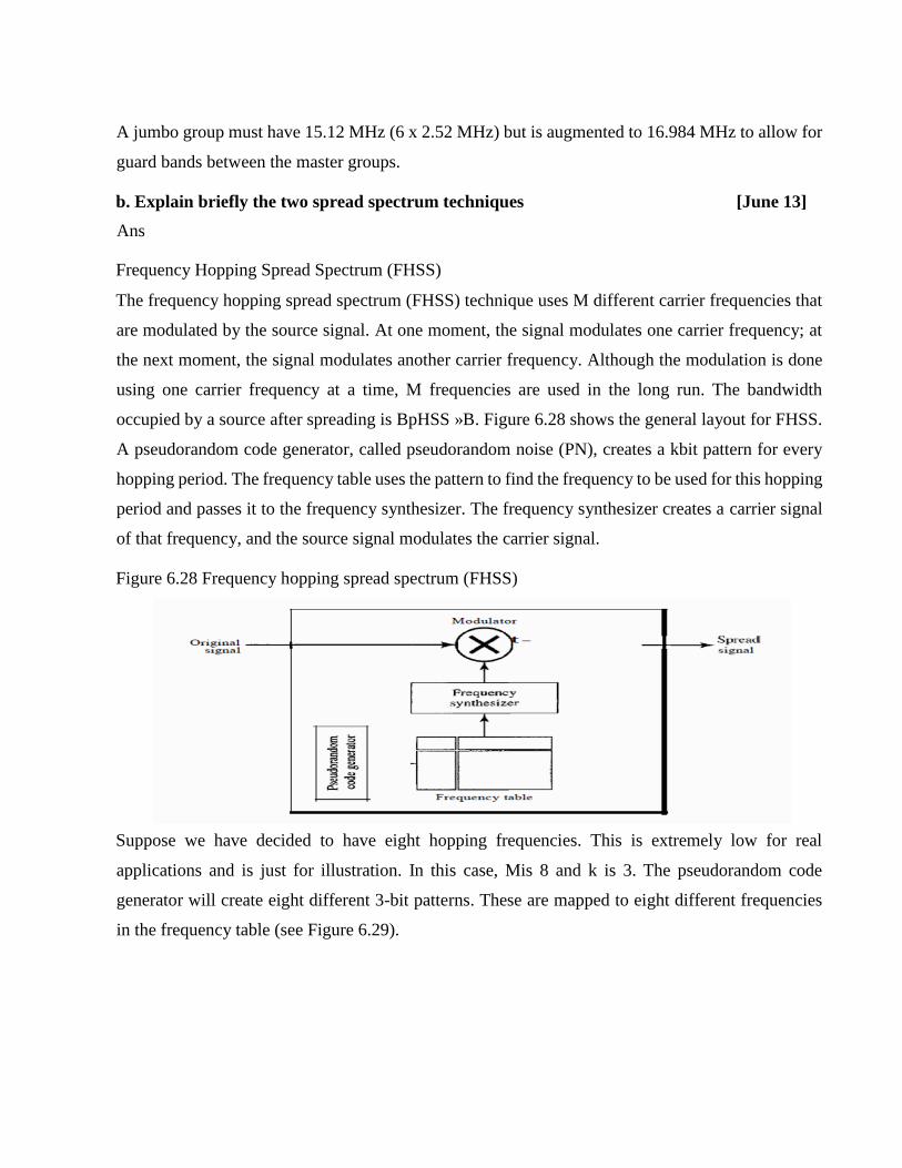
Frequency Hopping Spread Spectrum (FHSS)
The frequency hopping spread spectrum (FHSS) technique uses M different carrier frequencies that
are modulated by the source signal. At one moment, the signal modulates one carrier frequency; at
the next moment, the signal modulates another carrier frequency. Although the modulation is done
using one carrier frequency at a time, M frequencies are used in the long run. The bandwidth
occupied by a source after spreading is BpHSS »B. Figure 6.28 shows the general layout for FHSS.
A pseudorandom code generator, called pseudorandom noise (PN), creates a kbit pattern for every
hopping period. The frequency table uses the pattern to find the frequency to be used for this hopping
period and passes it to the frequency synthesizer. The frequency synthesizer creates a carrier signal
of that frequency, and the source signal modulates the carrier signal.
Figure 6.28 Frequency hopping spread spectrum (FHSS)
Suppose we have decided to have eight hopping frequencies. This is extremely low for real
applications and is just for illustration. In this case, Mis 8 and k is 3. The pseudorandom code
generator will create eight different 3-bit patterns. These are mapped to eight different frequencies
in the frequency table (see Figure 6.29).

Figure 6.29: Frequency selection in FHSS
The pattern for this station is 101, 111, 001, 000, 010, all, 100. Note that the pattern is pseudorandom
it is repeated after eight hoppings. This means that at hopping period 1, the pattern is 101. The
frequency selected is 700 kHz; the source signal modulates this carrier frequency. The second k-bit
pattern selected is 111, which selects the 900-kHz carrier; the eighth pattern is 100, the frequency is
600 kHz. After eight hoppings, the pattern repeats, starting from 101 again. Figure 6.30 shows how
the signal hops around from carrier to carrier. We assume the required bandwidth of the original
signal is 100 kHz.
Figure6.30
It can be shown that this scheme can accomplish the previously mentioned goals. If there are many k-
bit patterns and the hopping period is short, a sender and receiver can have privacy. If an intruder tries
to intercept the transmitted signal, she can only access a small piece of data because she does not know
the spreading sequence to quickly adapt herself to the next hop. The scheme has also an antijamming
effect. A malicious sender may be able to send noise to jam the signal for one hopping period
(randomly), but not for the whole period.
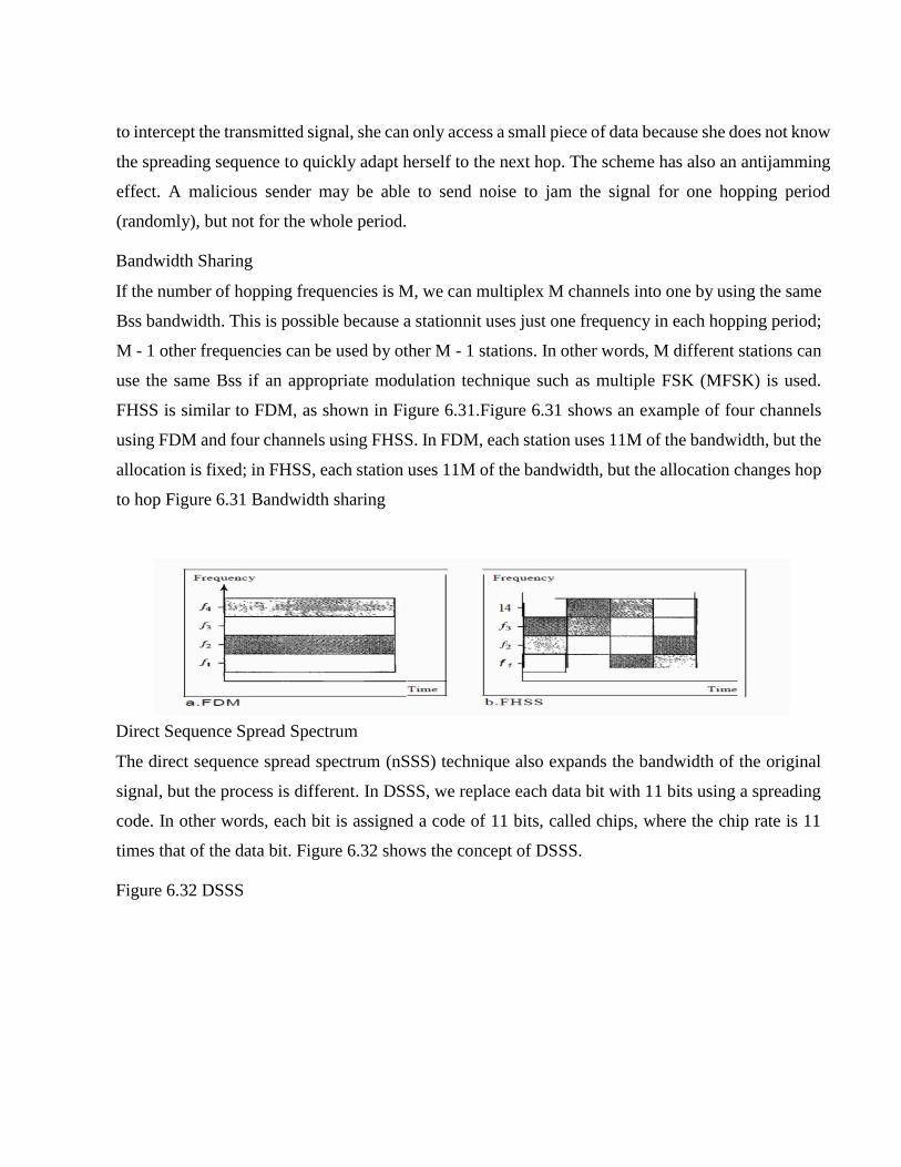
Bandwidth Sharing
If the number of hopping frequencies is M, we can multiplex M channels into one by using the same
Bss bandwidth. This is possible because a stationnit uses just one frequency in each hopping period;
M - 1 other frequencies can be used by other M - 1 stations. In other words, M different stations can
use the same Bss if an appropriate modulation technique such as multiple FSK (MFSK) is used.
FHSS is similar to FDM, as shown in Figure 6.31.Figure 6.31 shows an example of four channels
using FDM and four channels using FHSS. In FDM, each station uses 11M of the bandwidth, but the
allocation is fixed; in FHSS, each station uses 11M of the bandwidth, but the allocation changes hop
to hop Figure 6.31 Bandwidth sharing
Direct Sequence Spread Spectrum
The direct sequence spread spectrum (nSSS) technique also expands the bandwidth of the original
signal, but the process is different. In DSSS, we replace each data bit with 11 bits using a spreading
code. In other words, each bit is assigned a code of 11 bits, called chips, where the chip rate is 11
times that of the data bit. Figure 6.32 shows the concept of DSSS.
Figure 6.32 DSSS

As an example, let us consider the sequence used in a wireless LAN, the famous Barker sequence
where 11 is 11. We assume that the original signal and the chips in the chip generator use polar NRZ
encoding. Figure 6.33 shows the chips and the result of multiplying the original data by the chips to
get the spread signal. In Figure 6.33, the spreading code is 11 chips having the pattern 10110111000
(in this case). If the original signal rate is N, the rate of the spread signal is lIN. This means that the
required bandwidth for the spread signal is 11 times larger than the bandwidth of the original signal.
The spread signal can provide privacy if the intruder does not know the code. It can also provide
immunity against interference if each station uses a different code. Figure 6.33 DSSS example
Bandwidth Sharing
Can we share a bandwidth in DSSS as we did in FHSS? The answer is no and yes. If we use a
spreading code that spreads signals (from different stations) that cannot be combined and separated,
we cannot share a bandwidth. For example, as we will see in Chapter 14, some wireless LANs use
DSSS and the spread bandwidth cannot be shared. However, if we use a special type of sequence
code that allows the combining and separating of spread signals, we can share the bandwidth. As we
will see in Chapter 16, a special spreading code allows us to use DSSS in cellular telephony and
share a bandwidth between several users.
(May/Jun 2010)
4. a. Define synchronous TDM [Dec 14]
Ans:
Synchronous TDM is a digital process that allows several connections to share the high bandwidth
of a line Instead of sharing a portion of the bandwidth as in FDM, time is shared. Each connection
occupies a portion of time in the link. Figure gives a conceptual view of TDM. Note that the same
link is used as in FDM; here, however, the link is shown sectioned by time rather than by frequency.
In the figure, portions of signals 1,2,3, and 4 occupy the link sequentially.
b. Explain Amplitude modulation [Dec 14/Dec 15]
Ans: Amplitude Modulation
In AM transmission, the carrier signal is modulated so that its amplitude varies with the changing
amplitudes of the modulating signal. The frequency and phase of the carrier remain the same; only
the amplitude changes to follow variations in the information. Figure 5.16 shows how this concept
works. The modulating signal is the envelope of the carrier.
Figure 5.16 Amplitude modulation

As Figure 5.16 shows, AM is normally implemented by using a simple multiplier because the
amplitude of the carrier signal needs to be changed according to the amplitude of the modulating
signal.
AM Bandwidth
Figure 5.16 also shows the bandwidth of an AM signal. The modulation creates a bandwidth that is
twice the bandwidth of the modulating signal and covers a range centered on the carrier frequency.
However, the signal components above and below the carrier frequency carry exactly the same
information. For this reason, some implementations discard one-half of the signals and cut the
bandwidth in half.
Stalldard Balldwidth Allocatioll
The bandwidth of an audio signal (speech and music) is usually 5 kHz. Therefore, an AM radio
station needs a bandwidth of 10kHz. In fact, the Federal Communications Commission (FCC) allows
10 kHz for each AM station.
AM stations are allowed carrier frequencies anywhere between 530 and 1700 kHz
(1.7 MHz). However, each station's carrier frequency must be separated from those on either side of
it by at least 10 kHz (one AM bandwidth) to avoid interference. If one station uses a carrier frequency
of 1100 kHz, the next station's carrier frequency cannot be lower than 1110 kHz (see Figure 5.17).

c. Define PSK [Dec 14]
Phase Shift Keying
In phase shift keying, the phase of the carrier is varied to represent two or more different signal
elements. Both peak amplitude and frequency remain constant as the phase changes. Today, PSK is
more common than ASK or FSK. However, we will see Sh0l1ly that QAM, which combines ASK
and PSK, is the dominant method of digitalto- analog modulation.
Binary PSK (BPSK)
The simplest PSK is binary PSK, in which we have only two signal elements, one with a phase of
0°, and the other with a phase of 180°. Figure 5.9 gives a conceptual view of PSK. Binary PSK is as
simple as binary ASK with one big advantage-it is less
Susceptible to noise. In ASK, the criterion for bit detection is the amplitude of the signal; in PSK, it
is the phase. Noise can change the amplitude easier than it can change the phase. In other words,
PSK is less susceptible to noise than ASK. PSK is superior to FSK because we do not need two
carrier signals. Bandwidth Figure 5.9 also shows the bandwidth for BPSK. The bandwidth is the
same as that for binary ASK, but less than that for BFSK. No bandwidth is wasted for separating two
carrier signals.
5. With relevant diagrams explain the data transfer phase in a virtual circuit network.

[Dec 15]
Data Transfer Phase To transfer a frame from a source to its destination, all switches need to have
a table entry for this virtual circuit. The table, in its simplest form, has four columns. This means that
the switch holds four pieces of information for each virtual circuit that is already set up. We show
later how the switches make their table entries, but for the moment we assume that each switch has
a table with entries for all active virtual circuits. The following figure shows a frame arriving at port
1 with a VCI of 14. When the frame arrives, the switch looks in its table to find port 1 and a VCI of
14. When it is found, the switch knows to change the VCI to 22 and send out the frame from port 3.
Setup Phase: In the setup phase, a switch creates an entry for a virtual circuit. For example, suppose
source A needs to create a virtual circuit to B. Two steps are required: the setup request and the
acknowledgment. Setup Request: A setup request frame is sent from the source to the destination.
The following figure shows the process.
Teardown Phase: In this phase, source A, after sending all frames to B, sends a special frame called
a teardown request. Destination B responds with a teardown confirmation frame. All switches delete
the corresponding entry from their tables