vtt working papers 151 · demanding winter climates. various national activities have been...
TRANSCRIPT
VTTWORKINGPAPERS151VTT CREATES BUSINESS FROM TECHNOLOGY Technology and market foresight • Strategic research • Product and service development • IPR and licensing • Assessments, testing, inspection, certification • Technology and innovation management • Technology partnership
• • • VTT WO
RKIN
G PA
PERS 151 R
ECO
MM
END
ATIO
NS FO
R W
IND
ENER
GY PR
OJEC
TS IN C
OLD
CLIM
ATES
ISBN 978-951-38-7492-6 (URL: http://www.vtt.fi/publications/index.jsp)ISSN 1459-7683 (URL: http://www.vtt.fi/publications/index.jsp)
Recommendationsforwindenergyprojectsincoldclimates
VTT Working Papers
136 Toni Ahonen & Markku Reunanen. Elinkaaritiedon hyödyntäminen teollisen palveluliiketoiminnan kehittämisessä. 2009. 62 s. + liitt. 8 s.
137 Eija Kupi, Jaana Keränen & Marinka Lanne. Riskienhallinta osana pk-yritysten strategista johtamista. 2009. 51 s. + liitt. 8 s.
138 Tapio Salonen, Juha Sääski, Charles Woodward, Mika Hakkarainen, Otto Korkalo & Kari Rainio. Augmented Assembly – Ohjaava kokoonpano. Loppuraportti. 2009. 32 s. + liitt. 36 s.
139 Jukka Hietaniemi & Esko Mikkola. Design Fires for Fire Safety Engineering. 2010. 100 p.
140 Juhani Hirvonen, Eija Kaasinen, Ville Kotovirta, Jussi Lahtinen, Leena Norros, Leena Salo, Mika Timonen, Teemu Tommila, Janne Valkonen, Mark van Gils & Olli Ventä. Intelligence engineering framework. 2010. 44 p. + app. 4 p.
141 Juha Forström, Esa Pursiheimo, Veikko Kekkonen & Juha Honkatukia. Ydin-voimahankkeiden periaatepäätökseen liittyvät energia- ja kansantaloudelliset selvitykset. 2010. 82 s. + liitt. 29 s.
142 Ulf Lindqvist, Maiju Aikala, Maija Federley, Liisa Hakola, Aino Mensonen, Pertti Moilanen, Anna Viljakainen & Mikko Laukkanen. Hybrid Media in Packaging. Printelligence. 2010. 52 p. + app. 7 p.
143 Olavi Lehtoranta. Knowledge flows from incumbent firms to newcomers. The growth performance of innovative SMEs and services start-ups. 2010. 36 p. + app. 2 p.
144 Katri Grenman. The future of printed school books. 2010. 42 p.145 Anders Stenberg & Hannele Holttinen. Tuulivoiman tuotantotilastot. Vuosiraportti
2009. 2010. 47 s. + liitt. 5 s.146 Antti Nurmi, Tuula Hakkarainen & Ari Kevarinmäki. Palosuojattujen puurakenteiden
pitkäaikaistoimivuus. 2010. 39 s. + liitt. 6 s.147 Juhan Viitaniemi, Susanna Aromaa, Simo-Pekka Leino, Sauli Kiviranta & Kaj
Helin. Integration of User-Centred Design and Product Development Process within a Virtual Environment. Practical case KVALIVE. 2010. 39 p.
149 Tommi Ekholm. Achieving cost efficiency with the 30% greenhouse gas emission reduction target of the EU. 2010. 21 p.
150 Sampo Soimakallio, Mikko Hongisto, Kati Koponen, Laura Sokka, Kaisa Manninen, Riina Antikainen, Karri Pasanen, Taija Sinkko & Rabbe Thun. EU:n uusiutuvien energialähteiden edistämisdirektiivin kestävyyskriteeristö. Näkemyksiä määritelmistä ja kestävyyden todentamisesta. 130 s. + liitt. 7 s.
151 Ian Baring-Gould, Lars Tallhaug, Göran Ronsten, Robert Horbaty, René Cattin, Timo Laakso, Michael Durstewitz, Antoine Lacroix, Esa Peltola & Tomas Wallenius (eds.). Recommendations for wind energy projects in cold climates. 2010. 61 p.


EXPERT GROUP STUDY ON
RECOMMENDATIONS FOR
WIND ENERGY PROJECTS IN COLD CLIMATES
EDITION 2009
Submitted to the Executive Committee of the International Energy Agency Programme for Research and Development on Wind Energy Conversion Systems
Edited by
Ian Baring-Gould, NREL, USA
Lars Tallhaug, Kjeller Vindteknikk, Norway
Göran Ronsten, WindREN AB, Sweden
Robert Horbaty, ENCO Gmbh, Switzerland
René Cattin, MeteoTest, Switzerland
Timo Laakso, Pöyry Energy, Finland
Michael Durstewitz, Fraunhofer IWES, Germany
Antoine Lacroix, Natural Resources Canada, Canada
Esa Peltola, Technical Research Centre of Finland, Finland
Tomas Wallenius, Technical Research Centre of Finland, Finland

ISBN 978-951-38-7492-6 (URL: http://www.vtt.fi/publications/index.jsp) ISSN 1459-7683 (URL: http://www.vtt.fi/publications/index.jsp)
Copyright © VTT 2010
JULKAISIJA – UTGIVARE – PUBLISHER
VTT, Vuorimiehentie 5, PL 1000, 02044 VTT puh. vaihde 020 722 111, faksi 020 722 4374
VTT, Bergsmansvägen 5, PB 1000, 02044 VTT tel. växel 020 722 111, fax 020 722 4374
VTT Technical Research Centre of Finland, Vuorimiehentie 5, P.O. Box 1000, FI-02044 VTT, Finland phone internat. +358 20 722 111, fax +358 20 722 4374
2
Cover Photo: Three Vestas V27 wind turbines installed on St Paul Island, Alaska as part of a wind-diesel power system. Photo Credit: TDX Power, USA

3
Series title, number and report code of publication
VTT Working Papers 151 VTT-WORK-151
Author(s) Ian Baring-Gould, Lars Tallhaug, Göran Ronsten, Robert Horbaty, René Cattin, Timo Laakso, Michael Durstewitz, Antoine Lacroix, Esa Peltola & Tomas Wallenius (eds.)
Title
Recommendations for wind energy projects in cold climates Abstract
Mountainous and elevated areas, as well as many low land areas, around the world
offer large wind energy potential in demanding winter climates. The lack of knowledge
of cold and icing climate (CC) issues and the lack of proven and economic technological
solutions have limited the large-scale exploitation of these sites.
When developing wind energy projects in CC conditions, normal best practices
should be used to the extent possible, but also the additional risks that are involved in
CC wind energy projects must be assessed in detail. CC conditions directly affect site
access, working conditions, technology selection, loads, noise, health and safety, public
safety and energy production.
Recommendations for minimizing these additional risks are given in this report.
ISBN 978-951-38-9492-6 (URL: http://www.vtt.fi/publications/index.jsp)
Series title and ISSN Project number
VTT Working Papers 1459-7683 (URL: http://www.vtt.fi/publications/index.jsp)
Date Language Pages October 2010 62 p.
Name of project Commissioned by
Keywords Publisher Wind energy, cold climate, atmospheric icing, project development
VTT Technical Research Centre of Finland P.O. Box 1000, FI-02044 VTT, Finland Phone internat. +358 20 722 4520 Fax +358 20 722 4374

1. Executive summary / summary of recommendations
Preface
Mountainous and elevated areas around the world offer great wind energy potential in demanding winter climates. Activities have been conducted in a number of countries to master the difficulties that atmospheric icing and low temperatures pose for wind tech-nology. The current wind capacity in cold climates (defined as those that experience either icing events or temperatures lower than the operational limits of standard wind turbines) in Scandinavia, North America, Europe, and Asia, is about 60 GW. Increased experience, knowledge, and improvements in cold climate technology have enabled the economics of wind projects to become more competitive in relation to coastal and low-land wind projects. The internationally accepted procedures for testing and evaluating wind turbines or wind energy conversion systems encompass a variety of aspects, how-ever, although there is vast wind energy potential in cold climates, little attention has been paid to the environmental impacts of wind projects in these areas.
The large-scale exploitation of cold climate sites has been limited by our lack of knowledge about their special issues and the lack of proven and economical technologi-cal solutions.
The purpose of this report is to provide the best available recommendations on this topic, reduce the risks involved in undertaking projects in cold climates, and accelerate the growth of wind energy production in areas that have been overlooked. This docu-ment addresses many special issues that must be considered over the lifetime of a cold climate wind energy project. The importance of site measurements, project design, and system operation is emphasised.
Esa Peltola
Operating Agent, IEA RD&D Wind, Task 19
July 2009
NOTICE:
IEA Wind Task 19 functions within a framework created by the International Energy Agency (IEA). Views, findings and publications of IEA Wind Task 19 do not necessarily represent the views or policies of the IEA Secretariat or of all its individual member countries.
4

1. Executive summary / summary of recommendations
Contents
Preface ........................................................................................................................... 4
1. Executive summary / summary of recommendations ............................................... 7
2. Introduction ............................................................................................................. 10
3. Glossary .................................................................................................................. 12
4. Site considerations.................................................................................................. 16 4.1 Use available best practises ..................................................................................................... 16 4.2 Accessibility .............................................................................................................................. 16 4.3 Temperature ............................................................................................................................. 17 4.4 Ice ............................................................................................................................................. 17 4.5 Snow......................................................................................................................................... 19 4.6 Soil ............................................................................................................................................ 20 4.7 Technology for cold climates..................................................................................................... 20 4.8 Framework for economic risk .................................................................................................... 20 4.9 Public safety.............................................................................................................................. 21 4.10 Labour safety ............................................................................................................................ 22 4.11 Offshore applications ................................................................................................................ 22
5. Site measurements ................................................................................................. 24 5.1 Guiding principles and design................................................................................................... 24 5.2 Accessibility .............................................................................................................................. 25
5.2.1 Installation .................................................................................................................. 26 5.2.2 Site power .................................................................................................................. 26 5.2.3 Site communication .................................................................................................... 27
5.3 Towers ...................................................................................................................................... 27 5.4 Wind measurements ................................................................................................................. 28 5.5 Temperature ............................................................................................................................. 30 5.6 Ice detection.............................................................................................................................. 30 5.7 Atmospheric pressure ............................................................................................................... 31 5.8 Offshore applications ................................................................................................................ 31
6. Project design, planning and economics................................................................. 32 6.1 Project design ........................................................................................................................... 32
6.1.1 Environmental impacts ............................................................................................... 32 6.1.2 Impact of arctic climate on project design .................................................................. 33
6.1.2.1 Low temperatures..................................................................................... 33 6.1.2.2 Ice and snow ............................................................................................ 33
6.2 Climatic impacts on power production ...................................................................................... 35 6.2.1 Quantifying and estimating direct and indirect energy losses..................................... 35
5

1. Executive summary / summary of recommendations
6.2.1.1 Low temperature ...................................................................................... 35 6.2.1.2 Ice ............................................................................................................ 36
6.2.2 Estimating financial losses due to climate conditions ................................................. 38 6.3 Turbine selection....................................................................................................................... 38
6.3.1 Communications and turbine control .......................................................................... 39 6.3.2 Power control ............................................................................................................. 40
6.3.2.1 Passive stall ............................................................................................. 41 6.3.2.2 Active pitch............................................................................................... 41
6.3.3 De-icing and anti-icing systems.................................................................................. 41 6.3.3.1 Passive ice protection methods................................................................ 42 6.3.3.2 Active ice protection methods .................................................................. 42
6.3.4 Turbine cold climate packages................................................................................... 43 6.4 Site infrastructure...................................................................................................................... 44
6.4.1 Permafrost.................................................................................................................. 44 6.4.2 Foundation design...................................................................................................... 45 6.4.3 Grid connection .......................................................................................................... 46 6.4.4 Accessibility and turbine installation ........................................................................... 46 6.4.5 Special vehicles and tools .......................................................................................... 47
6.5 Maintenance ............................................................................................................................. 47 6.6 Decommissioning...................................................................................................................... 48 6.7 Public safety.............................................................................................................................. 48 6.8 Risk management and assessment .......................................................................................... 50 6.9 Summary of economic impacts ................................................................................................. 50 6.10 Offshore applications ................................................................................................................ 51
7. Project construction................................................................................................. 52 7.1 Time of year .............................................................................................................................. 52 7.2 Labor safety .............................................................................................................................. 52 7.3 Public safety.............................................................................................................................. 53 7.4 Offshore applications ................................................................................................................ 53
8. System operation .................................................................................................... 54 8.1 Operation .................................................................................................................................. 54 8.2 System maintenance and overhaul........................................................................................... 54 8.3 Environmental impact ............................................................................................................... 55 8.4 Labor safety .............................................................................................................................. 55 8.5 Public safety.............................................................................................................................. 56 8.6 Offshore applications ................................................................................................................ 56
9. Decommissioning.................................................................................................... 57 9.1 Turbine-specific issues ............................................................................................................. 57 9.2 Site-specific issues ................................................................................................................... 57 9.3 Environmental issues................................................................................................................ 57 9.4 Offshore applications ................................................................................................................ 58
References ................................................................................................................... 59
6
1. Executive summary / summary of recommendations
1. Executive summary / summary of recommendations
Mountainous and elevated areas around the world offer large wind energy potential in demanding winter climates. Various national activities have been conducted in a num-ber of countries to master the difficulties that atmospheric icing and low temperatures pose for wind technology. Our lack of knowledge of special cold climate (CC) issues and the lack of proven and economic technological solutions have limited the large-scale exploitation of these sites.
More generic wind development best practise guides provides a good starting point for developing a CC site. Those practices should be used to the extent possible, even though they do not normally consider CC issues. The additional risks that are involved in CC wind energy projects must be assessed in detail. CC conditions directly affect site access, working conditions, technology selection, loads, noise, health and safety, public safety and energy production.
The importance of thorough site assessment is emphasized in CC and icing condi-tions, which can complicate the measurements. It is the most important phase, however, as project decisions are based on the results. A thorough site measurement, including ice measurements for at least one year with the correct measurement devices is recom-mended. The complexity of a measurement program will vary greatly, depending on location and parameters. A proper measurement campaign also provides valuable in-formation on site access and working conditions.
Instrument and turbine manufacturers may have CC solutions available. Potential so-lutions for each project need to be surveyed because CC circumstances vary greatly. This is partly because commercial and prototype level anti-icing and de-icing devices and other solutions for low operational temperatures have been presented, but only lim-ited published information is available. Solutions for low temperatures are generally more mature, because most of that technology has been introduced in other fields of engineering. A distinctive feature is the lack of proven anti-icing and de-icing technol-ogy for different icing climates.
7

1. Executive summary / summary of recommendations
Icing may significantly influence energy production. There is no verified method for estimating ice-induced production losses. Simple approaches have been presented that can help assess the effects of extreme low temperatures although when combined with icing, these methods become less reliable. Additional costs that are related to working conditions, construction, and site access, can be limited with careful planning.
CC wind energy projects can, and need to, maintain high safety standards as such pro-jects involve higher risks than normal lowland or temperate climate undertakings. Plan-ners, operators, authorities, insurers, and investors should use an established risk evalua-tion method to determine the kinds of risks a CC wind turbine installation will face and the measures that have to be taken to avoid or decrease these risks. Although CC pro-jects will have additional risks, their assessments will be no different than that of other wind farm development projects.
More work is needed, especially in estimating ice-induced production losses and in developing countermeasures against ice. The climatic circumstances at CC sites demand high reliability of adapted technology.
A summary of recommendations as addressed in this document are:
Be aware of the extra risks and costs involved in CC wind energy production at early stages of the project.
Employ available best practises to the extent possible, even though they generally do not consider CC issues.
Instrument and turbine manufacturers may have CC solutions available. Conduct a survey to find solutions for each project understanding that CC circumstances vary greatly between different sites.
Perform a thorough site assessment measurement of at least one year with meas-urement devices, including ice measurements. Be aware that lower availability of wind measurements results in higher uncertainty in energy production estimate. This phase provides valuable information on site access and working conditions.
There is no standard method for estimating ice-induced production losses. Make the best estimate based on the results of site measurements.
Insure that in the project planning phase CC-related safety aspects, such as low-temperature working conditions and the risk of ice throw, are addressed. Maintain open and clear communication regarding risks, accidents and incidents.
Carry out a risk assessment that includes assessment of the quality of the selected turbine and experience and references of the installation company, contractors, and operator.
Include the results of the risk assessment as part of the specifications for turbine, equipment, manufacture, installation, and operation.
8

1. Executive summary / summary of recommendations
Consider the consequences of increased noise due to operation with iced-up blades and/or cylindrical sound propagation under stable atmospheric conditions.
Many wind turbine manufactures make CC packages for specific turbine lines, these packages differ by manufacture and should be considered carefully as part of the turbine selection process. Use anti- and/or de-icing systems if site condi-tions require and proven technology is available.
Insure that selected wind turbines are only operated under conditions for which they have been certified without extensive analysis and discussion with the turbine vendor.
9

2. Introduction
2. Introduction
Wind turbines in some cold climates may be exposed to icing conditions or tempera-tures outside the design limits of standard wind turbines. Standard turbines operating in extreme environments can experience considerable production losses and higher than normal loads, which in turn will cause financial losses and the risk of premature me-chanical failure. Although exact numbers are hard to assess some 60 GW of installed capacity is located in cold climate (CC) sites in Scandinavia, North America, Europe, and Asia. Narrowing this assessment to only regions with a high likelihood of extended CC operation; Scandinavia, Switzerland, Canada, and northern portions of the U.S. and China, conservatively 20 GW of wind are installed in CC areas [1, 2]. Additionally, microclimates with these same conditions are found in more temperate areas such as central and southern Europe, China, Japan, many parts of the United States, and loca-tions in the southern hemisphere such as Australia, New Zealand, and southern South America.
CC sites constitute a vast wind energy production potential and as fewer temperate sites become available, combined with the higher than expected cost of offshore wind development, large wind energy projects in CC are likely to be implemented. Increased experience and knowledge, combined with improvements in CC technologies, have en-abled such projects to become more competitive when compared to those at low re-source onshore and higher cost offshore sites.
Limited efforts have been made to assess the potential of wind development in arctic and arctic-like microclimates, but papers by Tammelin et al. [3, 4] report potential mar-kets of 20% of the installed capacity by 2010. This outdated estimate would correspond to some 40 GW in CC if combined with the forecast for 2010 wind production pre-sented in BTM’s 2008 World Market Update [5]. There is however an inherent lack of market studies for the potential of wind energy in cold climates on which manufacturers can base strategic production plans. The main reason for this has been a natural choice to focus initially on sites where no adaption is required.
Apart from requiring a shutdown, neither the International Electrotechnical Commis-sion (IEC) standard [6] for permissible loads nor standard certification requirements for cold climate certified wind turbines from Germanischer Lloyd WindEnergie GmbH
10

2. Introduction
[7, 8], deal with operation in icing conditions. The lower permitted temperature limit varies between wind turbine manufacturers and models. The aerodynamic effects of icing can be simulated by individual pitching of blades. However, there's currently no IEC load case which requires simulation of long time operation with a significant, > 5 deg, pitch angle offset.
The purpose of this report is to provide developers, owners, and operators of CC wind projects the best available information on this topic and thus reduce the risks and accel-erate the growth of wind energy production. This document also provides preparatory information that should benefit manufacturers, banks, and insurance companies.
The document includes sections on site considerations, measurement programs, pro-ject design, installation, operations and maintenance (O&M), and decommissioning. Each section addresses issues that are unique to wind energy in CCs. Although the document may be read cover to cover, sections are meant to be stand alone, providing specific recommendations for the different stages of project life.
These recommendations aim to provide solutions for the CC-specific challenges and reduce the cost of wind energy by lowering the social, technological, and economic risks.
The governing conditions in CCs are not necessarily included in the design limits presently covered by national and international standards for wind turbine design and implementation, although in many cases standard turbines may be installed at sites that experience CC conditions.
The recent interest in offshore wind development increases the applicability of these issues as turbines installed in the shallow waters off northern Europe and off the coast of New England in the United States also face icing conditions.
11

3. Glossary
3. Glossary
The following section provides definitions for terminology used in this report that may be new to wind energy experts not previously familiar with CC. General wind energy terms have not been included intentionally.
Cold climate (CC) Sites at which significant icing events or periods with tempera-tures lower than the operational limits of standard wind turbines may occur.
Rime ice A smooth-surfaced, usually transparent dense formation of ice. Its crystalline structure is rather irregular, surface uneven, and its form resembles glazed frost. Supercooled cloud droplets with some wind are needed to form rime. Rime ice can be defined with respect to density, hardness and appearance: Hard rime is a granular, usually white, ice formation. It forms ice granules among which there is trapped air which causes the white color. The density of hard rime ice ranges typically between 100 and 600 kg/m3. Hard rime ice adheres firmly on surfaces making it very difficult to remove it. Soft rime is a fragile, snow-like for-mation formed mainly of thin ice needles or flakes of ice, when the air temperature is well below 0C. The growth of soft rime starts usually at a small point and grows triangularly into the windward direction. The density of soft rime is less than 100 kg/m3, and it can be easily removed. [9]
Rime is the most common type of in-cloud icing and often forms vanes on the windward side of linear, non-rotary objects, i.e. ob-jects which will not rotate around the longitudinal axis due to eccentrically loading by ice. During significant icing on small, linear objects the cross section of the rime vane is nearby trian-gular with the top angle pointing windward, but as the width (di-ameter) of the object in-creases, the ice vane changes its form. The accretion rate for rime mainly varies with:
12

3. Glossary
Dimensions of the object exposed Wind speed Liquid water content in the air Droplet size distribution Air temperature [10]
Glaze ice A smooth, transparent and homogenous ice coating occurring when freezing rain or drizzle hit a surface.[11]
Glaze is the type of precipitation ice having the highest density. Glaze is caused by freezing rain, freezing drizzle or wet in-cloud icing and normally causes smooth evenly distributed ice accre-tion. Glaze may result also in formation of icicles, and in this case the resulting shape can be rather asymmetric. Glaze can be accreted on objects anywhere, when rain or drizzle occurs at temperatures below freezing point. The surface temperature of accreting ice is near freezing point, and therefore liquid water, due to wind and gravity, may flow around the object and freeze also on the leeward side.
The accretion rate for glaze mainly varies with:
Rate of precipitation Droplet size distribution and water content Wind speed Air temperature[12]
Wet snow A high density snow with high liquid water content above about 3% [13] or up to 15% [14] created at temperatures very close to freezing can appear quite sticky and adheres to structures. Freez-ing wet snow develops a strong bond to structures.
Wet snow is, because of the occurrence of free water in the partly melted snow crystals able to adhere to the surface of an object. Wet snow accretion therefore occurs when the air temperature is just above the freezing point. The snow will freeze when wet snow accretion is followed by a temperature decrease. The density and adhesive strength vary widely with, among other things, the frac-tion of melted water and the wind speed. [15]
Dry snow Snow with a solid crystal structure which typically will not stick to structures and easily drifts in the wind.
Ice accumulation The amount and rate at which ice accumulates on structures, spe-cifically on wind turbine blades, towers, and guy wires. Accumu-
13

3. Glossary
lation depends on many factors and affects turbine performance, noise and safety aspects. Accumulation must be sufficiently well estimated or measured to correctly estimate the need for de-icing and anti-icing equipment.
Icing event The Cost 727 project defines Meteorological icing as the duration of a meteorological event or perturbation which causes icing [unit: time]. Icing event can be characterized by the meteorologi-cal conditions, and possibly with additional information such as
the total amount of ice accreted on a standard (reference) object during the icing event and
the average and maximum accretion rate [16]
Duration of icing The time ice stays on a turbine, structure, or instrument. It differs from an icing event in that once a structure is covered with ice it may remain for a considerable time before it melts or is removed. This information is important to assess the need for and impact of anti-icing or de-icing equipment. This is defined as Instrumental icing by Cost727.
Wind chill The rate of heat loss from exposed skin caused by wind and cold. Recent research has produced an updated wind chill factors [17]. More information is provided in [18]. Wind chill has a great ef-fect on worker productivity and safety.
Ice Detector A device that detects the existence of atmospheric icing. Was initially developed for the aviation industry, in which it sees the most usage. Have generally proved unreliable for most wind ap-plications, especially in areas with severe icing, primarily due to the very different operational conditions. The term “Ice detector” is often used as a common term for devices that measure icing- (accretion during an icing event), ice (as in the accumulated amount) and ice load (the forces applied by ice) although these may represent three different and distinct sensors. An existing In-ternational Standardization Organization (ISO) standard exists for ice measurements (ISO 12494), however it has not been deter-mined how relevant this is for the wind industry.
Ice Detection The act of detecting icing or ice. There are three major parame-ters that are considered important when assessing ice and icing in relation to wind power development:
14

3. Glossary
the start of an icing event (to determine when to turn off the turbine or start anti-icing technology)
icing event severity (to what degree should anti-icing technology be implemented) and
ice persistency (once ice has formed on a structure and how long it will take to naturally become ice free).
Ice detection may be done with a, or combination of, ice detec-tors, however due to the lack of historical reliability, many other approaches have been used to asses the icing environment, such as anemometers, video links and wind turbine power production. Additionally, current and maximum ice load, as well as the type (density) of ice may be of importance.
15

4. Site considerations
4. Site considerations
The first step in developing any wind farm project is to select potential candidate sites. A huge number of factors, most of which are applicable also to cold and arctic climates, must be addressed as part of this process. This section addresses some additional con-siderations that become important during this initial stage, and provides an overview of some key elements to development in CCs, such as the impact of extremely low tem-peratures and icing.
4.1 Use available best practises
Best practise guidelines for implementing wind energy projects are available from many national, international, professional, and industrial organisations. These should be used as far as possible, even though they do not generally consider CC. An example is the “Best practise guidelines for wind energy development” presented in [19]. However, CC-specific issues such as accessibility, temperature, ice, snow, energy potential, tech-nology, economic risk, public safety, infrastructure, and labour safety will require addi-tional thought.
The best practises guidelines, even without CC-specific topics, provide relevant in-formation regarding CCs as wind energy in CCs will presumably benefit from the rapid development of offshore wind energy technology, an application that, like CC, requires high technical availability with limited O&M.
4.2 Accessibility
Icing and snow drifts can make vehicle access difficult or impossible without snowmo-biles or other over snow transport. Access roads are likely to face seasonal restrictions because of ice, snow drifts, and even avalanches during the winter and possibly swampy conditions or flooding during the spring and summer. Storm frequency and avalanche dangers should be assessed, to plan for possible use of snowploughs or specialised equipment such as snow machines (snowmobiles), tracked snow vehicles, and possibly
16

4. Site considerations
even helicopters. Roads need to be marked with poles that will protrude above snow-drifts for snowploughs and other vehicles. Flood frequencies and high stream levels caused by snow melt and soil type must also be studied to design adequate road sur-faces, culverts, fords, and bridges that will keep the site accessible during the spring and summer.
A power supply will be required during the assessment phase of a project to heat the measuring instruments, as access will be required to fuel the generators. Turbines should be selected according to site accessibility, taking into account road and bridge limitations for heavy cranes and trucks. The logistics of turbine installation must be planned according to seasonal and climatic limitations, and special care may be required to avoid damage to equipment during transportation.
4.3 Temperature
Temperature consideration is critical to project development, construction, operation, and decommissioning. A wind turbine contains components that often can be readily adapted to CC. The lowest operational temperature limit for the turbine is usually gov-erned by qualities of steel and welding. The wind resource below the operational tem-perature limit of the turbine design cannot be harvested. Consequently, the local tem-perature distribution must be measured along with the wind speed and icing events dur-ing site investigation to enable a turbine to be selected with the correct CC modifica-tions. This is discussed in greater depth in chapter 5, Site Measurements.
Air density variations affect the power output of wind turbines. Based on the equation of state for an ideal gas, air at –30C is 27% denser than at 35C, resulting in a similar increase in power output at the same wind speed. This may cause the generators in pas-sive stall controlled wind turbines to operate above its rated power, which could require the turbine to be shut down at low temperatures or risk causing damage to the generator or whole turbine system.
Unlike icing, in many areas extreme low temperatures caused by winter clear sky ra-diation often associated with high pressure zones coincides with still air and thus low wind turbine production. The low temperature effects on humans are addressed in sec-tion 4.9.
4.4 Ice
Icing on any exposed part of the turbine can occur in the form of wet snow, freezing rain or drizzle, or in-cloud icing. Icing can cause decreased performance of the turbine with ice accumulation on the turbine blades, Figure 1, and excess vibration problems from uneven blade icing or making control hardware, such as anemometers and wind
17

4. Site considerations
direction sensors, to stop functioning. De-icing equipment allows an object to ice up before the ice is removed; anti-icing, by definition, implies prohibiting ice from building up. The national meteorological services regularly predict icing at low altitudes for the aviation industry however the relevance of such ice prognosis for wind energy is still un-known since regular icing measurements are not carried out and correlating turbine per-formance to general icing predictions have not been systematically considered. Designers of offshore wind turbine foundations in CCs must also consider the effects of sea ice.
Figure 1. Ice accumulation on the leading edge of wind turbine blades causes reduced turbine availability and if operated, potentially damaging loading and increased public safety concerns. Photo credit: Kent Larsson, ABvee, Sweden.
Icing is a key parameter for CC in project development, construction, operation, and decommissioning. The performance of an iced-up wind turbine will normally degrade rapidly as the ice accumulates. If the icing continues without proper anti-icing, the tur-bine will either stop because of excess vibrations or disconnect from the grid because of increased aerodynamic drag that slows the rotor down. The wind resource outside the operational icing limit of a wind turbine design cannot be harvested. Consequently, the local icing distribution must be measured along with the wind speed and temperature during the site investigation so that an optimal CC wind turbine selection can be made. This is discussed in greater depth in chapter 5, Site Measurements.
Icing of structures can be computationally modelled, however in most cases important information such as the Liquid Water Content (LWC) and Median Volume Diameter (MVD) of the droplet size distribution are required. This information is usually only available from sophisticated research test sites although in some instances visibility can
18

4. Site considerations
be used to estimate LWC while MVD can be roughly assessed based on vertical air ve-locity [20]. As described in the work by Dobesch et al. [21] “it may be possible to use small-grid weather forecast models to perform an approximation of these values. Such models also include information about vertical air stability which influences the LWC and MVD.” LWC and MVD, and to a lesser extent relative humidity, are fundamental parameters in icing research.
Heavily iced up meteorological measurement masts and power lines may also break with or without exposure to wind.
De-icing equipment might suffice to avoid long downtimes or to fulfil possible future power performance requirements set by the licensing authorities. Atmospheric icing of off-shore structures should be considered if in-cloud icing can occur at subzero temperatures.
Recent research indicates that a once-per-revolution (1P) imbalance in torque, caused by a change in individual blade aerodynamics is typical even for lightly iced up wind turbine rotors. The occurrence of 1P variations in torque, and thereby electrical power, can be used as an early indication of icing.
Designers should consider the influence of fatigue caused by extended operation with iced blades. Icing might also cause surfaces to be unserviceable, which would prevent turbine access. Ice thrown from the blades or that falls from the tower or nacelle may pose a significant safety hazard.
Icing on turbine towers and climbing structures should be carefully considered. Tubu-lar towers with internal climbing devices are strongly recommended if there’s a signifi-cant risk of icing. Measures, such as placing the transformer in the tower or insulating the rest of the tower from the heated base, may be considered to reduce interior ice build up caused by condensation.
4.5 Snow
Snow is quite easily suspended and transported by wind [22]; it forms drifts wherever there is an interruption or discontinuity in the airflow [10]. Wind turbine nacelles are generally not airtight compartments, and in fact usually incorporate many openings to provide cooling. Snow can accumulate inside the nacelle, damage equipment, and prove detrimental to the electrical machinery. It can also obstruct openings and prevent normal air circulation. Heated surfaces, for example on heated anemometers and ice detectors, have been shown to melt snow and, as a consequence, create artificial icing conditions during snow fall. Although not yet proven, de- and anti-icing systems based on heated blade surfaces are likely to act in a similar manner during snowfall.
19

4. Site considerations
4.6 Soil
An initial geotechnical analysis is critical in every wind energy development project. Permafrost depth and foundations add another element to the development of CC sites. The changing soil conditions in arctic areas due to climate change must also be consid-ered. More discussion regarding foundations with permafrost is provided in section 6.4.1.
4.7 Technology for cold climates
Due to many of the issues discussed above; higher air density, turbine icing, and low temperatures; specific turbine technology, such as a well-adapted power control system, must be assessed and included as part of the site selection process. Technology choice extends beyond just the turbine selection, but also materials to be used for foundations, road design and other balance of system components.
4.8 Framework for economic risk
Independent of the climate, a multitude of economic risks are associated with the use of wind power. Operating in arctic and arctic-like climates adds costs and performance vari-ability that must be assessed when any wind turbine site or project is considered. A frame-work for assessing this risk must be developed as part of the project development process.
Examples of these risks are:
Increased initial costs of the turbine project because of limited installation schedules and higher equipment and installation costs. Due to a short construc-tion season, foundations might for example have to be installed one season be-fore the turbines are erected.
Increased downtime or power reduction caused by icing events over seasons or even in relation to forecasted spot markets if a storm results in an un-expected icing event.
Turbine downtime and liability because of concerns for public safety from tur-bine blades and tower ice throw.
Long exposure of rime ice, which may increase fatigue loading and cause pre-mature failures.
Increased downtime caused by extreme low temperatures in combination with any potential increase in power from higher air density in passive stall controlled wind turbines.
Increased maintenance costs because of low temperatures and the likely higher average downtime between repairs because of turbine inaccessibility.
20

4. Site considerations
Assessment of the economic impact of potential de- or anti-icing and low tem-perature operation equipment.
Risk mitigation strategies such as blade de-/anti-icing equipment, increased preventive maintenance, and pre-stocking replacement parts are available, but these increase the operational costs of the turbine and of the overall project. Any economic risk assess-ment should assess and weigh such strategies. Detailed site and meteorological informa-tion will be crucial to any risk mitigation calculation.
4.9 Public safety
Ice on turbine blades and towers can pose a safety risk for the general public depending on the site being considered, Figure 2. The fact that no serious accidents caused by ice throw have been reported is no reason to think otherwise. Special technical solutions may have to be implemented to prevent accidents associated with the use of turbines in CCs that is accessible to the public. Additionally, an assessment should be made of legal protection to limit the risks associated with wind applications at specific sites.
Turbine operation with iced blades may not be permitted in certain countries or permitted only in the case of rime ice, as glaze ice is considered more dangerous. However, rime ice can be almost as dense as glaze ice, so there is no obvious reason to make such an excep-tion. As visibility can be very poor under active icing conditions, warning signs should be closely spaced unless the area is accessible only via specific posted entry points.
Figure 2. Ice falling or being thrown off a wind turbine poses a safety threat to turbine maintenance staff and depending on turbine siting, the general public. Photo credit: Jeroen Van Dam, USA.
21
4. Site considerations
The areas of potential ice throw should be calculated and the proximity of developed ar-eas, roads, and tourist infrastructure such as ski slopes and lifts must be taken into account in placing the turbines. More specific information on setbacks and other design consid-erations are provided in Chapter 6. The turbines are likely to attract visitors if permissi-ble. Visitor numbers to surrounding areas and to the site in question should be analysed and a risk assessment made. Local authorities may already have issued ordinances that restrict placement and/or operation of wind turbines due to the risk of ice throw.
4.10 Labour safety
Outdoor activities should generally be avoided when temperatures are very low. Hu-mans’ capability to focus on safety and problem solving quickly decreases in adverse conditions, such as low temperatures, high winds, and during precipitation. Thus, apart from being more costly by requiring extra time and equipment, low temperatures may pose significant safety hazards.
Logistics for the comfort and safety of O&M staff should be planned and accounted for. Heated accommodations, proper clothing, shelter and machine design to allow ser-vice and maintenance during extremely cold or adverse weather should be implemented. An emergency evacuation plan for injured or stranded personnel is necessary.
4.11 Offshore applications
Sufficient knowledge of the wind resource and icing conditions is required to minimize the risk associated with offshore wind farms in cold climates. Developers can rely on hydrological and climatological data, although these generally do not provide enough detail for full-scale development. Erecting meteorological platforms is a more common option, although in areas where sea ice is likely to occur, towers must be designed with this in mind. For tower and turbine installation, over-the-ice transport may be more cost effective than using sea vessels.
Various cost-effective ways to access wind turbines in a frozen or semi-frozen sea need to be considered. Hovercraft, helicopters, and ice breakers are options. Ice roads can be built to enable access by ordinary land vehicles. Such roads are reinforced by removing the snow and if needed, by sluicing, and need to be clearly marked to enable driving in low visibility conditions. Turbine access in rough seas must also be addressed.
Icing and rough seas increase the risks for service craft. The icing of boats that weigh less than 500 tons and move faster than 15 knots is not well studied or understood. Many factors, including salinity, humidity, wave height, temperature, wind speed, and boat size, contribute to the icing process, which can cause vehicles to flounder. Using sheltered locations, travelling with the wind and waves, and reducing speed to avoid breaking waves decrease the risk of boat icing.
22

4. Site considerations
The ice breaking capability of the foundation will influence structural loading. Winters with difficult icing conditions should be used for determining maximum ice thickness. The possibility of ice drift needs to be considered, as it might trigger structural vibrations.
Even located offshore, ice from the rotor blades may pose a safety hazard. Ice on blades and/or structures must be detected and appropriate precautions taken.
23

5. Site measurements
5. Site measurements
Monitoring the wind resource at a potential site is usually one of the first steps of any proposed development. The complexity of a measurement program will vary greatly depending on the location and the parameters that need to be measured. The CC issues and icing in particular complicate matters further. Issues associated with the implemen-tation of monitoring programs in CCs, including accessibility and measurements, are addressed in this section.
5.1 Guiding principles and design
Monitoring systems implemented in arctic and icing climates need additional power for the use of heated sensors and other equipment, greatly expanding installation require-ments. Difficult weather can also be an obstacle for site visits, so more effort should be put into the measurement campaign so that data retention is insured. Details like the quality and strength of all equipment, lightning rods, mounting booms, cable straps, wind vanes, and anemometers must be considered. In addition equipment covers and locks should be selected so that those can be used with winter cloves.
Since conditions will likely be quite harsh, redundant measurements and expanded data logging capability to ensure a high percentage of data capture are also recom-mended. It should also be understood that the use of redundant and heated sensors will not guarantee accurate wind resource data collection. Additionally, other parameters such as outside temperature, ice accumulation and ice duration should be measured. This information will allow an accurate assessment of potential turbine availability due to conditions outside of the turbines normal operating regime and to allow the economic assessment of different mitigation options, such as cold weather packages and de or anti-icing approaches.
Measurement towers in locations with potential icing conditions should be grossly oversized to account for the possible accumulation of ice on guy wires and towers, Fig-ures 3 and 4.
24

5. Site measurements
Figure 3. Meteorological tower with heavy icing.
Figure 4. Collapsed meteorological tower, likely due to heavy icing.
5.2 Accessibility
Meteorological towers in CCs can usually be accessed with snowmobiles or other over snow transport during winter. Rapid weather changes are likely to pose safety risks that require emergency shelter at the measurement site. To provide safe travel to and from the site when visibility is poor, reflective route markers (long poles) with short separa-tion distances should be installed in early winter. Limited site accessibility also justifies multiple sensors for high-priority signals such as wind speed and temperature.
25

5. Site measurements
5.2.1 Installation
Meteorological monitoring installations should be set up during warm weather for im-proved safety and to increase the quality of measurements. Winter installation is clearly possible, but should be generally discouraged, Figure 5. For remote areas, planning must begin in midwinter so the measurement program can start during the summer. Ground con-ditions, such as permafrost or seasonal changes in soil conditions must also be considered.
Figure 5. Meteorological tower installation in Alaska. Photo credit: Doug Vought, USA.
5.2.2 Site power
Power for heated sensors can often be a challenge when grid power is not available. Small wind turbines, PV, diesel engines, and hybrid power systems are options. A diesel engine should be combined with a battery bank to decrease engine run time and reduce the use of diesel fuel, especially for towers requiring small amounts of power. Diesel engine air intake must be kept open and ice free, a chimney with a U bend on top pro-tects against drifting snow. Care must also be taken with engine cooling, as radiator fans tend to stick at low temperatures if they are not operated continuously leading to the use of large passive radiators. If possible, remote monitoring should be implemented to al-low early warning of power system problems. The design and implementation of remote power systems are non-trivial tasks even under more temperate conditions. If possible, organizations that are well acquainted with remote power systems in harsh environ-ments should be employed, Figure 6.
26

5. Site measurements
Figure 6. Accessing power system in a remote location. The whole structure apart from the air inlet to the engine has been buried. Photo credit: Lars Tallhaug, Norway.
A heated sensor installed as close as possible to the site where power is available can be used if the winds at the two locations can be expected to be reasonable similar. The sen-sor can then be redundant to the unheated ones at the site. The relationship between the site and the heated sensor must be established during non-icing periods to allow the heated sensor to be used when the unheated sensor is not operating.
5.2.3 Site communication
Site communication at remote CC sites can be challenging. Consequently, the simplest communication will be regular visits by the staff who conduct measurements and re-trieve data from system loggers. Since a great effort and expense is going to be required for any arctic climate measurement program, the small incremental cost to improve reli-ability is quite appropriate. Measurement data should be checked regularly, as the qual-ity of data depends on the reliability of subsystems and ultimately how well supervision can be arranged.
5.3 Towers
Ice build-up should be recognised as a selection criterion for the tower if icing is likely at the installation site, as towers have to be designed to support heavy ice loads [23]. Met masts are usually of a very thin and slender construction as the more slender the met masts, less will they influence atmospheric measurements. When the wind trans-ports supercooled droplets towards the mast they will freeze on the tower.
27

5. Site measurements
For example, a mast with a mass of around 1000 kg can collect 5000 kg of ice on the mast structure and guy wires in heavy icing conditions. Such ice loads can be critical to the mast, especially if the ice load is combined with high wind speed. Additionally the lower ends of tower guys (where they are attached to anchors) need to be protected in severe icing climates, as ice build-up on the guy wires may slide down, damaging cable clamps and/or anchor rods.
The standard steel structures become brittle in low temperatures, so some caution is necessary when tubular steel towers are erected during winter. The tubular tower may buckle, so these should not be erected in extreme low temperatures.
Before erecting a met mast in a region with ice, a calculation of the highest ice load and the highest wind load should be calculated. For masts for long term installation the standard ISO 12494 states that a combination of the three (3) year maximum ice load with a fifty (50) year maximum wind speed should be used. For constructions that are designed to be short term in nature and if the site can be closely monitored, the maxi-mum wind speed and ice loading can be reduced. This type of calculations will usually show that it is a problem to use tubular towers in icing climates. A properly designed lattice tower is usually the only solution. This might increase the cost for non-permanent met masts significantly compared to locations in climates without icing.
5.4 Wind measurements
Wind measurements in CCs can be challenging. Many factors can reduce their quality and availability. Anemometers may stop or slow down, wind vanes might stop, ice build up on booms or lightning rods may affect the measurements.
As a rule, heated sensors are recommended at sites with potential icing. Because most heated sensors have disadvantages like high mass and sensitivity to vertical wind, conven-tional cup anemometers should also be used. A significant difference in measured average wind speed is a likely indication that the unheated sensor is being impacted by icing.
Various types of heated sensors such as shaft heated, completely heated, and heated ultrasonic are available. The completely heated sensors have varying amounts of power output that will dictate the conditions under which they will remain ice free. No sensor can stay ice free under all conditions. A shaft heated sensor should not be considered ice free, but is suitable to keep the bearing at constant temperature, improving readings in cold climates. In an icing environment, ice build up on mounting booms, guy wires, lightning rods, tower, and other components should be expected. The dimensions of the iced structures and their influence on the measurements must be considered, Figure 7. More information on the operation of ice-free wind sensors can be found in [24, 25].
28

5. Site measurements
Figure 7. The impact of ice build-up on mounting hardware must be considered to insure accu-racy of wind speed and direction measurements. Photo credit: VTT, Finland.
A Site Icing Index and an Instrument Class Index for the proper selection of sensors depending on the required availability due to icing has been described by Fikke S. et al. as part of the COST 727 project. [26]
At sites where icing occurs less frequently, filtering techniques can be used to remove samples that are affected by icing. For example, a significantly lower standard deviation of the wind direction signal occurs when sensors are iced up. A filter that combines the standard deviation of wind direction and temperature will allow identification and re-moval of most periods when wind speed measurements are likely to be compromised by icing [27]. Because the icing process is slow, samples should be removed some hours before and after a suspected icing event to ensure data quality. This technique might not be appropriate for all climatic conditions.
Met masts should generally be installed inside the wind farm area. If grid power is not available, an autonomous power supply is recommended. The power supply should be well tested in harsh climate. A measurement campaign with low availability is likely when using untested power supply equipment. Another possible solution is to install a heated sensor in an existing mast with grid power. The mast should be located as close as possible. How close is strongly dependent of the terrain. The heated sensor can be correlated to the masts inside the wind farm during no-ice conditions, and hence be used to fill the gaps in series for the non-heated anemometer.
The use of other measuring techniques such as Sodar and Lidar has been applied in cold climates and some data has been obtained. Generally speaking, due to the remote
29
5. Site measurements
nature of most sites the use of Sodar for long term measurements have not been overly helpful. Recent initial work with Lidar technologies in remote applications is more promising, but use in icing conditions and /or complex terrain with vertical flow can be difficult. Extensive testing of both devices in climates exposed to moderate to severe icing have not been completed, so these devices should only be used to provide secon-dary site assessment until further research has been completed. More information and testing on these technologies will be undertaken over the next few years and should provide further feedback over time.
5.5 Temperature
Radiation shields around temperature sensors need ventilation to work properly. The ventilation in conventional small shields with lids may become filled with ice or incased in snow, and provide false readings. Large housings such as those used on meteorologi-cal stations may be necessary.
5.6 Ice detection
The installation of an ice detector is recommended in connection with site measure-ments at any location where icing is expected to occur. There are a number of ice detec-tors currently available although no single one can be used for all intended purposes. Only few, if any, of the ice detectors are well proven. Their primary purpose is to meas-ure the occurrence and intensity of icing, although duration, type, density and accumu-lated mass of ice are also important characteristics. Measurement of icing occurrence and intensity allows for an assessment of the potential ice-induced turbine down time and enables an assessment of the requirements for anti- or de-icing technology. The duration of ice on surfaces can be used to assess the reduced turbine availability and potential economic impact if no anti- or de-icing technology is employed on the turbine. The active icing time, intensity, and duration of iced surfaces is needed to estimate the site specific icing and ice climates.
Different ice detecting methods are suitable for different climates and for different purposes. Some ice detectors measure the frequency variation in a sonic or vibratory wave; others monitor the capacitance between metal strips. Equipping the measurement mast with one properly heated and one unheated anemometer to estimate wind resource measurements is relatively inexpensive and advisable. This arrangement gives an over-all picture of the icing climate. Acquiring information such as time series of cloud base height from the nearest airport and comparing that with the measured data is also advis-able. These two methods are likely to give a fairly good assessment of the time that ice is likely to affect the operation of the wind turbines.
30

5. Site measurements
A dew point detector that has been designed for subzero temperature operation could also provide valuable information of high humidity as the frost point is a good indicator of in-cloud icing.
Based on the work completed under the COST 727 research framework [28], two ice detectors have shown an ability to measure icing events for wind site applications, these are the IceMonitor from Combitech, Sweden and the Goodrich light freezing rain sensor 0847LH1, U.S.A. Expanded testing of a number of additional ice monitors are currently underway.
5.7 Atmospheric pressure
Measuring pressure in an icing environment is similar to measuring pressure at a con-ventional site. Care should be taken to ensure that the pressure sensor is being exposed to the surrounding atmospheric pressure since, if the air intakes are obstructed by ice, a false reading may occur.
5.8 Offshore applications
Erecting a meteorological platform or mast to measure the wind resource and icing con-ditions offshore should be considered well in advance of installing an offshore wind farm. Offshore meteorological platforms are expensive, and will likely require different environmental and regulatory assessments than onshore measurement programs. It might be worth considering whether winter over ice access is more cost effective than by sea. The tower should be equipped with strain gauges to measure the force created by breaking ice on its foundation as this will be required for the proper design of the tur-bine tower and foundation.
31

6. Project design, planning and economics
6. Project design, planning and economics
An investor generally intends to maximize the profit of a project and clearly the cost of production from a site affects the total project economics and may vary over time and season, especially in open energy markets. This implies that maximum profit is not, in generally liberalized electricity markets, equivalent to always maximizing the difference between energy production and energy consumption.
As with any project, there are always trade-offs between engineering designs and the economic impact of those designs. Installing anti-icing equipment on a turbine will im-prove energy production during some periods but will come at an additional expense and will consume power and accrue extra maintenance costs. These trade-offs will have to be assessed to determine the most cost-effective approach that meets legal or legisla-tive requirements.
Although the costs of power generation in CCs are generally higher than in more temperate areas, many factors may add to the value of that power. Compared to other power generation options, wind may still provide the lowest cost of energy even at the elevated costs associated with CC operation. In this section we will address additional design issues that should be considered in the early stages of project development.
6.1 Project design
The following section describes general initial consideration that should be taken into account at the very start of the project design process.
6.1.1 Environmental impacts
Many projects are implemented in microclimates that, due to their short growing sea-sons, contain fragile ecosystems with limited animal and avian populations, thus requir-ing special consideration. Additionally, flora and fauna in these extreme climates have generally been studied less than those in other climates, so assessing impact may be difficult. However, the limited number of affected specimens and the reduced existing impacts of most remote sites may allow for a simpler environmental impact assessment.
32

6. Project design, planning and economics
A critical aspect of environmental impact is the length of time flora will need to re-generate after it has been disrupted, primarily for the installation of the wind project. There are many ways to reduce this impact such as conducting heavy construction dur-ing the winter when snow or ice roads can be used instead of more permanent ones. Wood planking-based corduroy roads that are removed after summer maintenance can reduce local impact, as can boardwalks instead of trails or paved roads.
Any organisation that conducts an environmental impact assessment in an arctic or mountain climate needs to have specific experience in these areas, as the microclimates can be very different from normal wind development projects.
6.1.2 Impact of arctic climate on project design
In addition to the clear impacts on turbine design and operation addressed previously, a number of environmental impacts must be considered during the project design and tur-bine selection process. As we have seen, most issues relate to low temperatures or to ice and snow.
6.1.2.1 Low temperatures
Low temperatures affect several turbine selection decisions. Access to the turbine na-celle should be protected, usually by tubular towers with enclosed ladders or elevators, Figure 8. Tubular towers will not protect service personnel from the extreme tempera-tures, and climbing lattice towers under these conditions is very dangerous. Rubber coatings designed for arctic regions can improve the safety of metal ladders and stairs, which can become slick with ice and snow. Service personnel will generally need to perform winter maintenance in a nacelle that can offer some protection from the ele-ments. Also, adverse conditions may prevent evacuation for medical or work related emergencies, so contingency planning for such occurrences must be undertaken early in the implementation process.
6.1.2.2 Ice and snow
Snow build up around the turbine can bury doorways and make tool sheds inaccessible. Turbines installed in climates with large amounts of snow should include multiple entry points or doors high above the ground plane, Figures 8 and 9.
33

6. Project design, planning and economics
Figure 8. The Northern Power Northwind 100 allows service personnel to climb inside the tower and perform all general turbine maintenance from inside the nacelle. Photo credit: Ian Baring-Gould, USA.
Figure 9. Turbine in Gütsch Switzerland is built on a ~10 meter concrete foundation with two levels of access to the turbine base and storage for extra turbine equipment. Photo credit: Mar-kus Russi, Switzerland.
34

6. Project design, planning and economics
Tool sheds and storage rooms should be integrated and accessible from the inside of the tower or designed to allow access during the winter, Figure 9. Ice and snow commonly freeze doors and hatchways closed, especially those exposed to freeze-thaw cycles, such as hatches in the turbine nacelle. Care should be taken to protect all external doors and locks from water, which can freeze and make entry impossible. Finally, all external doors should open inward to allow egress even after heavy snowfall.
Blowing snow can also be problematic and will enter most vents or openings. All doors and hatches should be sealed and the venting designed to limit the access of blow-ing snow. All areas around venting should be equipped with drains to remove water from melting snow and all electronic equipment should be sealed. Moving parts such as yaw drives and hydraulic cylinders should be protected to prevent ice accumulation that can inhibit movement. A chimney with an inverted U-bend on top of a container can supply air for proper ventilation.
6.2 Climatic impacts on power production
When siting a new wind power plant, understanding the potential loss of availability is crucial to determining if the project is economically feasible and what mitigation meas-ures might be cost effective. This section provides the framework for assessing the eco-nomic impact of operating turbines in CC.
6.2.1 Quantifying and estimating direct and indirect energy losses
Temperature and atmospheric icing will impact the energy production from a wind turbine.
6.2.1.1 Low temperature
Temperatures below the operational limit of the wind turbine will prevent it from oper-ating and thus impact turbine availability. The effect of extreme low temperatures on energy production may be estimated with
))(1(
T
T dttfEOE
where ET is energy output in low temperature, EO Energy output, T low temperature limit of the turbine and f(t) probability density function of air temperature. A basic as-sessment of power losses due to low temperatures would be to use a typical year of co-incident wind and temperature data from a location in question, then eliminate all wind speed data at times when the temperature is below the rated operating temperature of the turbines being considered. There is clearly some potential overlap with downtime ex-
35

6. Project design, planning and economics
pected for icing, however at extremely low temperatures for most CC wind turbines, simultaneous extreme low temperatures and active icing events are rare.
A normal distribution may be assumed if no defined function is available for the tem-perature function. In calculating energy output, one should notice the correlation be-tween wind speed and temperature. In many areas very low temperatures are tied to high-pressure systems during which winds are often weak. Based on measurement data incorporating wind speed and temperature, an analysis should be conducted to calculate the loss of energy production when temperatures are below the specific threshold as defined by the turbine manufacture. A statistical analysis can be conducted based on long term diurnal and seasonal temperatures and wind speed profiles, allowing a gener-ally accurate assessment of power production losses due to low temperatures.
Conversely however, the higher air density caused by very cold air can increase pro-duction of wind turbines. Leclerc and Masson [29] report cases in which stall-controlled wind turbines were generating power well above expected outputs at low temperatures. For instance, 5-minute averaged power output of 89 kW was recorded for a 65-kW tur-bine. A 220-kW turbine peaked at 360 kW, leading to excessive loading and eventually generator failure [20]. These cases all occurred in very cold weather. Such a phenome-non cannot be expected to increase the annual production significantly, but it should be considered when conducting power plant power production assessments and the poten-tial of higher loading, not only on the generator but on the whole electrical and me-chanical system should be considered and addressed.
6.2.1.2 Ice
Ice build-up on the blades usually reduces lift and increases drag, which results in re-duced power output and eventually turbine shutdown. The amount of reduced power depends on the amount of ice, blade design, and turbine control. Detailed information about wind speed, duration of ice accumulation, duration and amounts of ice, tempera-ture, and how the turbine is affected by ice are needed to calculate the reduced power output. It is also necessary to know how these parameters correlate in time as a time domain calculation is usually recommended. If the turbine is simply shut down in the event of icing, the calculation is simplified, but an understanding of the duration of the downtime and its relation to high wind events in the time domain remain critical to un-derstanding the project power output of the wind system.
The two most important parameters for estimating energy production losses caused by ice are the number of hours ice affects the turbine and the performance of a wind turbine when the blades are covered with ice. Atmospheric icing reduces the aerodynamic per-formance of a wind turbine rotor significantly, as the blade aerodynamics are very sensi-tive to extra surface roughness caused by ice [30]. Significant decrease in production with stall-regulated wind turbines is to be expected, even after short icing periods. This
36

6. Project design, planning and economics
impact is less severe with pitch regulated wind turbines, specifically in light icing condi-tions, as recent studies by the Technical Research Centre of Finland (VTT) show, Fig-ure 10 [31].
Figure 10. The impact of wind turbine control on the power curves of passive stall and active pitch regulated wind turbines in different icing conditions. Source VTT Finland.
Production estimates can be made based on the results of thorough site measurements, however, these parameters can be notoriously difficult to obtain. Parameters that need to be at hand include:
Duration of ice accumulation Persistence of ice Frequency distribution of icing Temperature Wind speed and direction Cloud height observations.
A great deal of recent work has been undertaken to assess icing, but more specifically the impacts of icing on wind turbine production. Detailed airfoil modelling or statistical analysis based on these parameters and estimated production losses that are based on local ice climate and turbine technology seem to provide the most accurate estimates. However, no method has been verified.
The difficulty of estimating ice-induced production losses relates to the aerodynamics and control system of a wind turbine. A method presented by Wallenius [31] considers these subjects, but it lacks a reliable method to represent the effects of icing to the aero-dynamics of wind turbine. The aerodynamic degradation can be done, but connection between a particular icing conditions and degradation due to it is not completely veri-fied. More work is needed in this area before a reliable production estimate method or tool can be presented. Theoretical and measured performance of an iced-up wind tur-bine is presented in [32].
37

6. Project design, planning and economics
6.2.2 Estimating financial losses due to climate conditions
Financial losses result from an assumed increased risk in CC, lost energy production caused by ice, low temperatures and the costs of more demanding maintenance. If the site is remote, malfunctions that require site visits may extend the downtime. Financial losses should be estimated so that the effects of ice and low temperature on energy pro-duction are taken into account based on the expected impacts described in section 6.2.1. It should be noted, however, that both low temperatures and icing events may occur simultaneously in the time domain, so care should be taken to insure that downtime for both low temperatures and icing are not double counted from a turbine availability point of view. Mitigation measures, such as cold climate packages available from some tur-bine vendors can then be assessed to determine if the additional cost of capital for such measures is justifiable. Energy consumption of adapted technology should also be in-cluded in the energy production estimate according to the best information from the manufacturer. The effect on the duration of stoppages caused by the site location and access should be determined during the project planning phase. Clearly, the economical uncertainty associated with cold climate projects is higher than at conventional sites.
Since the increased uncertainty lowers the 75% and 90% production probability of the wind project (typically referred to as P75 and P90), it is especially important to pay at-tention to recommended practice when designing a project.
6.3 Turbine selection
Many problems caused by low temperatures and icing environments can be addressed by selecting wind turbines and adapted features that are designed for arctic climates. Examples of some adapted technology are heating elements, CC hydraulic oil and grease, anti-icing or de-icing equipment for blades, heated sensors, and sealing specific turbine components that may be susceptible to internal icing or frost.
Current international standards for wind turbine do not address CC conditions, simply stating that operation outside of these specified ranges can impact performance and maintenance contracts. For this reason specific technology has to be adopted outside the scope of most national and international standards. The current standards state only that any turbine installed at locations outside of “normal” atmospheric conditions should have the class S rating, a requirement that, at no fault to the standards authors, is woe-fully inadequate. Wolff [33] and Ganander [34] discuss icing impacts in current and proposed standards in greater detail.
Germanischer Lloyd has developed a voluntary certification for turbine operation in cold climates, allowing manufacturers to certify turbines for operation to specific inter-national standards [35, 36]. This, however, simply requires the implementation of a ice detection equipment or procedure and then the requirement that the turbine is to be shut
38

6. Project design, planning and economics
off during times when ice is present on the blades. This procedure may not be applica-ble, or even desired, for turbines operating in certain icing climates.
A standard IEC based classification does exist based on annual average and maximum wind speeds as well as wind turbulence. Due to the impacts of high density cold air, changing the class of the turbine being considered for your specific site may be appro-priate. The exact site conditions and turbine specifications should be undertaken in con-sultation with the wind turbine manufactures and project engineers.
The following section addresses many of the impacts of installing wind turbines in cold and arctic microclimates.
6.3.1 Communications and turbine control
Whether a project includes many turbines or only one, communication is essential to successful operation. For example, a wind turbine with iced blades may not be operated in certain regions and in some countries icing or vibration alarms cannot legally be reset without a visit to the site to assess the potential dangers associated with starting the wind turbine wind with existing ice on the blades. Communication including remote sensing, web based or direct video cameras and other relevant sensors can in some areas be used to enable a legal remote restart procedure of the turbine. For maintenance pur-poses a more advanced level of self- or remote diagnosis is usually beneficial due to the potential difficulty of getting to remote sites. Many communication options are avail-able, each with a specific cost and level of capability. An assessment of the local condi-tions will likely indicate which specific method is most appropriate; however, erring on the conservative side will likely pay off greatly over the life of the project.
CC adapted sensors need to be weather and ultraviolet (UV) resistant and must spec-ify low temperature use. Modern sensors such as ultrasonic anemometers and data ac-quisition networks can be connected via fibre optical cables. However, fibre cables for CC operation need to be adapted for such use by using, for example, non-freezing gel that is pumped into conduits that surround the interior cables to prevent water ingress and subsequent ice formation as shown in [37]. The gel will also protect a cable against breaking if exposed to a) unforeseen external loads by a maintenance crew and b) movements when cable attachments are deteriorating.
Cable attachments and connectors will occasionally break after prolonged exposure to CC and weather-resistant cable ties are not sufficient in cold climates. Weather-resistant nylon 6.6 [38] has greater resistance to UV, but weather-resistant nylon 12 is needed in CCs and under high moisture conditions.
39

6. Project design, planning and economics
6.3.2 Power control
The choice of power control technology will influence energy production and loads ex-pected by a wind turbine and its subcomponents. Special attention should be paid to loading the gear box, generator, and transformers. These should never be operated be-low rated temperature or above rated power or wind speed. A wind turbine generally requires a reliable wind speed signal from an anemometer mounted on the nacelle. An iced anemometer will prevent the turbine from operating or can result in control errors as shown for data collected for a wind turbine in Germany, Figure 11. For this reason, heated redundant control anemometers should be specified, although this will not guar-antee proper turbine operation. Unsymmetrical icing will usually cause a wind turbine to vibrate excessively, causing a vibration fault and stopping the turbine. Operation in light icing conditions however might cause a low amplitude vibration and a once per revolution variation in torque and power. If frequent cyclic loading of this nature is not properly detected it might cause unexpectedly high loads or cyclic fatigue failures.
0
100
200
300
400
500
600
700
0 5 10 15v [ m/s ]
P [
kW
]
Jan '08
Dec '07
Figure 11. Measured power curve for an operating wind turbine in Germany. The second power curve indicates errors in wind speed measurements due to an iced anenometer, which results in controller errors and production losses. Source ISET, Germany.
Passive stall wind turbine blades will usually experience icing of the leading and trailing edges when not operating and if icing occurs at low wind speeds. Icing at high wind speeds will cause an upwind, parked passive stall wind turbine to develop ice on the pressure side of the airfoil. Grid synchronization might not even be possible in stall regulated turbines as the aerodynamic drag caused by ice accretion will prevent the tur-bine generator from reaching the RPM needed for designed voltage and frequency. Anti-icing systems intended for use on operating wind turbines are generally more ex-pensive than de-icing while the turbine is stopped. If wind energy in CCs is to be im-
40

6. Project design, planning and economics
plemented on a large scale, wind turbine investors and licensing authorities will pre-sumably require power production independent of icing. Downtime caused by icing that lasts longer than a few hours may be unacceptable.
6.3.2.1 Passive stall
Passive stall combined with constant speed can be a cost-effective solution only if the air density at a site does not vary too much or icing is infrequent or, if frequent, relevant mitigation measures are implemented. Although simple to implement, the drawbacks of passive stall during non-optimal conditions are under- and overproduction, which result in energy losses in some cases and overloading of the turbine system in others. The rea-son for this is that a constant speed turbine which uses passive stall is controlled indi-rectly via the fixed blade pitch setting and ultimately by the local aerodynamic angle of attack of the blade. Consequently, each turbine blade (there may be many in a wind farm) initially has to be mounted at a fixed pitch angle that assumes an “optimal” air density at the site. The initial blade pitch setting might later have to be changed to in-crease energy capture or reduce maximum power, a time-consuming and costly process for fixed pitch wind turbines.
Constant speed combined with passive stall is not recommended unless a) the pitch angle can be easily adjusted to significant shifts in air density, b) a lower maximum power can be accepted during low air density conditions, or c) passive stall is combined with variable speed. The advantages of simplicity in the passive stall control strategy should not be underestimated in CCs.
6.3.2.2 Active pitch
Controlling the power by pitching, active stall, or variable speed operation will enable the maximum power to be independent of air density variations. Icing will usually re-duce the efficiency of an airfoil [18] although the consequences will depend on the im-plementation of the control system. For example, a pitch-controlled wind turbine with blades iced and operating above rated wind speed, might try to increase the aerody-namic angle of attack (increase the rotating torque) by decreasing the blade pitch angle and vice versa for the active stall turbine. Eventually, if the difference between nominal power, based on the measured wind speed and actual power, is too large, the wind tur-bine is either shut down or de-icing countermeasures are activated.
6.3.3 De-icing and anti-icing systems
In areas with heavy icing or a large number of days with mild icing, the use of anti- or de-icing can be used to improve turbine energy production. Anti-icing prevents the for-
41

6. Project design, planning and economics
mation of ice; de-icing removes the ice when a predetermined amount has accumulated. The methods currently used to prevent and remove ice from wind turbine rotors can be divided into two main categories: active and passive.
6.3.3.1 Passive ice protection methods
The passive methods take advantage of the physical properties of the blade surface to eliminate or prevent ice. Black blades and stick-free surface coatings are passive meth-ods. Some European operators have coated blades with different materials and special paint. They concluded quite early that these methods are not sufficient to prevent icing [39].More recent work in anti-ice coating at Zurich University of Applied Studies and the University of Manitoba of Canada have shown promises in laboratory and wind tun-nel testing, but have not been applied in full scale field testing [40]. Flexible blades may passively hinder and remove ice, but there is no published information on the subject. Many semi-passive methods such as the active pitching of the turbine blades, starting and stop cycles, and facing the blades into the sun are used to remove ice from turbine blades. Although these methods may work in light icing environments when limited instances of blade icing need to be addressed each year, their use has not been scientifi-cally verified and repeated usage may cause increases damage to the turbine.
6.3.3.2 Active ice protection methods
Active methods that have been developed at least to a prototype stage are based on thermal systems that remove the ice by applying heat to the blade. The inherent difficul-ties and maintenance requirements of chemical or pneumatic impulse-based-systems, which are familiar to the aircraft industry, have prevented these methods from being developed for wind turbine purposes. The electrical ice protection system, which is based on electrical heating elements, and a heating system that is based on hot air circu-lation inside the blade structure, are commercial ways to protect the blades against ice.
The electrical ice protection system consists of a heating membrane or element that is applied on the blade surface. The heat is obtained from electrical heating elements em-bedded inside the membrane or from the heating element that has been laminated into the blade structure. Such thermal ice prevention systems are simple and have been used in the aerospace industry for many years. In wind energy applications such heating sys-tems were developed in mid 1990s and those systems have now been tested for over 10 years. The technology is still at the prototype level because of limited markets [41, 42] although this may change shortly with the increased in wind energy in CC.
The other thermal method is to circulate hot air inside the blade shell with a hot air blower. This kind of system works well in milder climates where icing occurs mainly at temperatures close to 0°C. However, as the turbines become bigger and the blades
42

6. Project design, planning and economics
longer, shell structures become thicker and thermal resistance becomes higher, in prac-tice this means that very high temperatures are needed inside the blades to keep the outer surfaces free of ice even in mild conditions. Considering the maximum operating temperatures of thermoset composites that are being applied wind turbine blades, in the future using such temperatures inside the blade structure to keep the blades free of ice will be challenging.
The current anti-icing technology calls for power requirements at 6%–12% of the ca-pacity for turbines ranging from 220 to 1000 kW while the anti-icing technology is in operation. [43] The power that is required to remove accretions already formed (de-icing) by rapid heating far exceeds this capacity. The heating demand also varies ac-cording to the airflow condition on the blade.
6.3.4 Turbine cold climate packages
The definition of a CC site calls for adapted technology. CC packages and even adapted wind turbine designs are available from manufacturers engaged in delivering wind tur-bines for CCs. CC packages (apart from anti-icing systems) are readily available, rea-sonably priced, and generally include heating and material selection. The following modifications are usually included in a wind turbine CC package, although this varies by manufacture:
Control system
Selected sensors, particularly wind speed and wind direction
Yaw system
Gear box
Nacelle to allow a reasonably comfortable work environment for turbine mainte-nance.
The selection incorporates materials and techniques such as steel quality and welding that are suitable for use in CCs. Special lubricants (oils, greases, and hydraulics) are also typically used.
Special CC turbine modifications such as avoiding LCD displays that can freeze or encapsulating circuit boards to protect from condensation may also be incorporated. It is also good to determine as part of the turbine selection process the level of experience the specific manufacturer has in installing turbines in CCs. Black blades or leading edges might be profitable where there is enough solar radiation to deice the structure.
As previously stated, Germanischer Lloyd has developed a voluntary certification for turbine operation in cold climates, allowing manufactures to certify turbines for opera-tion to specific international standards. This may or may not be appropriate for actual operation in cold climates.
43

6. Project design, planning and economics
6.4 Site infrastructure
Low temperatures and ice affect the choice and design of the specific wind turbine and many aspects of the project balance of system components. This section provides a brief examination of some key aspects.
6.4.1 Permafrost
Permafrost can be divided in two categories: ice-poor and ice-rich. Construction tech-niques must be adapted to the type of permafrost found at a specific site. If the wind turbine foundation can be constructed in areas of non-frost-susceptible sand or gravel or on rock that is free of ice, the design of the foundation can be undertaken as if no perma-frost were present. Ice-poor permafrost conditions are likely the most difficult, requiring excavation to a stable ground layer, either ground rock or a solid permafrost layer that is not going to change over time. Standard foundation design can then be used.
Ice-rich permafrost is usually composed of fine grain soils that contain a significant amount of frozen water. In this instance much of the structural integrity of the founda-tion design will rely on the ice structure itself, meaning that thawing must be prevented to retain good load-bearing capability and avoid volume change [10]. For a heavy struc-ture like a wind turbine foundation, the design should be extended beyond the annual frost zone and well into the permafrost. The frozen soil maintains its strength and keeps the foundation stable [10]. In that case, the permafrost must remain frozen and protected from heat that may come from the heaters inside the towers. This is typically done by keeping the foundation structure off the ground, allowing free air movement on the sur-face, and then using thermo siphons to keep the ground frozen, Figure 12. In some areas applying thermal ground cover can also assist in maintaining a strong permafrost layer. In some regions the active layer of the permafrost, the portion that thaws during summer months and then refreezes during the winter, can be quite large, require extensive foun-dations to insure that the tower is well anchored. Model analysis should also be under-taken since the effective height of the tower can in effect change seasonally.
44
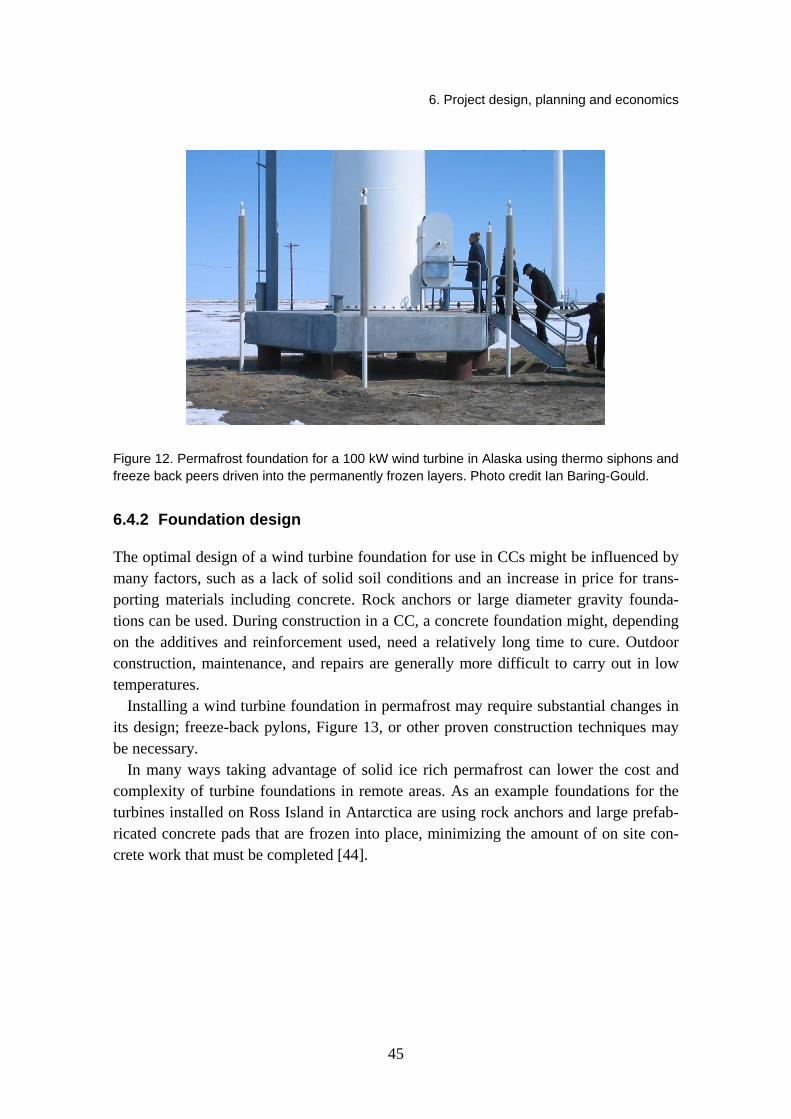
6. Project design, planning and economics
Figure 12. Permafrost foundation for a 100 kW wind turbine in Alaska using thermo siphons and freeze back peers driven into the permanently frozen layers. Photo credit Ian Baring-Gould.
6.4.2 Foundation design
The optimal design of a wind turbine foundation for use in CCs might be influenced by many factors, such as a lack of solid soil conditions and an increase in price for trans-porting materials including concrete. Rock anchors or large diameter gravity founda-tions can be used. During construction in a CC, a concrete foundation might, depending on the additives and reinforcement used, need a relatively long time to cure. Outdoor construction, maintenance, and repairs are generally more difficult to carry out in low temperatures.
Installing a wind turbine foundation in permafrost may require substantial changes in its design; freeze-back pylons, Figure 13, or other proven construction techniques may be necessary.
In many ways taking advantage of solid ice rich permafrost can lower the cost and complexity of turbine foundations in remote areas. As an example foundations for the turbines installed on Ross Island in Antarctica are using rock anchors and large prefab-ricated concrete pads that are frozen into place, minimizing the amount of on site con-crete work that must be completed [44].
45
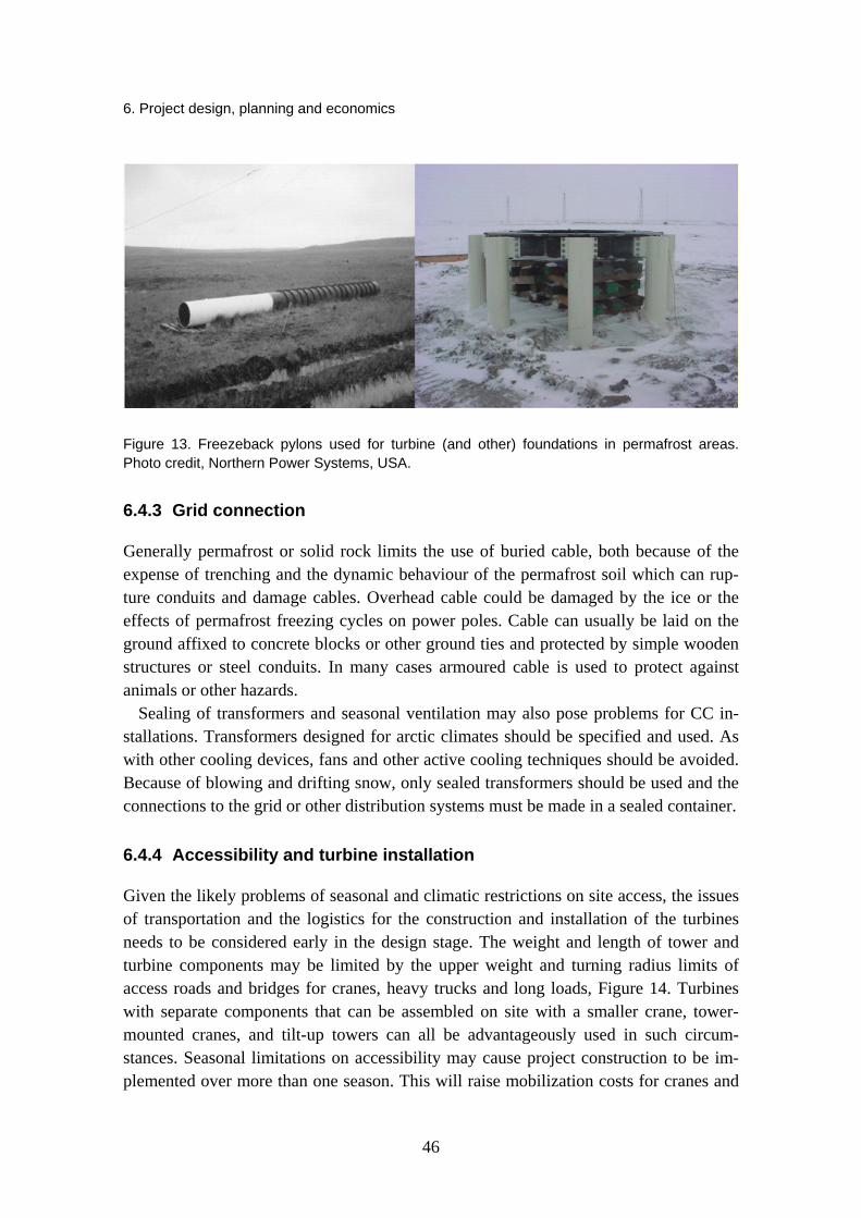
6. Project design, planning and economics
Figure 13. Freezeback pylons used for turbine (and other) foundations in permafrost areas. Photo credit, Northern Power Systems, USA.
6.4.3 Grid connection
Generally permafrost or solid rock limits the use of buried cable, both because of the expense of trenching and the dynamic behaviour of the permafrost soil which can rup-ture conduits and damage cables. Overhead cable could be damaged by the ice or the effects of permafrost freezing cycles on power poles. Cable can usually be laid on the ground affixed to concrete blocks or other ground ties and protected by simple wooden structures or steel conduits. In many cases armoured cable is used to protect against animals or other hazards.
Sealing of transformers and seasonal ventilation may also pose problems for CC in-stallations. Transformers designed for arctic climates should be specified and used. As with other cooling devices, fans and other active cooling techniques should be avoided. Because of blowing and drifting snow, only sealed transformers should be used and the connections to the grid or other distribution systems must be made in a sealed container.
6.4.4 Accessibility and turbine installation
Given the likely problems of seasonal and climatic restrictions on site access, the issues of transportation and the logistics for the construction and installation of the turbines needs to be considered early in the design stage. The weight and length of tower and turbine components may be limited by the upper weight and turning radius limits of access roads and bridges for cranes, heavy trucks and long loads, Figure 14. Turbines with separate components that can be assembled on site with a smaller crane, tower-mounted cranes, and tilt-up towers can all be advantageously used in such circum-stances. Seasonal limitations on accessibility may cause project construction to be im-plemented over more than one season. This will raise mobilization costs for cranes and
46

6. Project design, planning and economics
installation crews and will influence the selection of turbines. Similar considerations apply to the construction of transmission lines to grid connections.
The issue of accessibility and the likely additional costs of transportation and installa-tion in cold climates, including the possible need for helicopters, can have important impacts on the overall economic viability of a project. They must be carefully analyzed in the early stages.
Figure 14. Trucks transporting blades, tower sections, and heavy components may require spe-cial treatment do to poor or restrictive road conditions. Photo credit: Markus Russi, Switzerland.
6.4.5 Special vehicles and tools
The need of special vehicles and tools should be identified before construction work begins. The ability of large cranes to ascend and descend steep roads must be defined, especially for installations in mountainous areas. If heaters are needed to tighten bolts at low temperatures, this must be assessed before construction begins.
6.5 Maintenance
Heated work premises should be available for the convenience and safety of mainte-nance staff. Basic tools should be available at sites with difficult access to allow im-proved efficiency and reduce the need to bring all tooling on each service trip. Accessi-bility depends on local conditions, which may result in downtime or force staff to re-main at the site for long periods. Annual maintenance visits should be scheduled for the best possible climatic conditions and the easiest possible access to the site. Special transportation such as snow machines, snow cats and bulldozers will be required. Re-
47

6. Project design, planning and economics
pairing unexpected faults in a CC is usually more time consuming than in more temper-ate climates.
6.6 Decommissioning
Site decommissioning includes its own challenges in the climates covered by this text. Many have limited growing seasons and very slow plant growth, so reconditioning can be costly and time consuming. Efforts can be made at the start of the project and during project development to expedite this process. Project installation and decommissioning can be concentrated during the winter when snow or ice roads can be used to protect sensitive vegetation. Wood planking-based corduroy roads that are removed after summer maintenance can reduce local impact, as can boardwalks instead of trails or paved roads.
Environmental preparation and assessment after decommissioning can also take longer than normal projects and are usually more costly. Funds should be set aside dur-ing the project to cover these costs.
Most damage occurs during site construction and decommissioning. Careful planning can reduce the impacts and prevent costly environmental reconditioning.
6.7 Public safety
Ice that is thrown from turbine blades or that falls from the tower can be dangerous and cause serious damage. Any structure close to turbines should be designed to withstand the impact of ice thrown from the turbine blades and overhangs installed above doors. Signs that warn of falling ice, visual warnings after icing events and horns or other ac-tive attention devices implemented before turbine start-up should be incorporated to help ensure public safety, Figure 15.
48

6. Project design, planning and economics
Figure 15. Warning signs for falling ice. Photo credit: Lars Tallhaug, Norway.
Simple formulas for calculating the zone of likely ice throw is presented in [1, 31]. For an operating turbine the following has been suggested for ice throw:
5.1)( xHDd
and for a turbine still standing:
15
)2/( HDvd
where d = maximum falling distance of ice (in m) D = rotor diameter (in m) H = hub height (in m) v = wind speed at hub height (in m/s).
49

6. Project design, planning and economics
Seifert et al. [45] suggest that the formulas should be used only as a rough estimate and recommend more detailed calculations, including risk assessment.
In many cases the area around the turbine will be accessible to the public either inten-tionally or because fencing is buried under snow. Alarm and security measures need to be incorporated into the project design.
In addition, turbines can be chosen with ice detection and blade heating to minimize the dangers of ice throw occurrences. Insurance coverage should be planned for, and the necessary analyses done to estimate visitor frequency and plan mitigation measures.
6.8 Risk management and assessment
Planners, operators, authorities, insurers, and investors should use a risk evaluation to determine the kinds of risks a wind turbine installation in a CC will face and implement measures to avoid or decrease these risks [46]. Although projects in CCs will have addi-tional risks (most of which have been addressed in this document), their assessment will be no different than other wind farm development projects.
General considerations include an assessment of:
Quality and standard of turbine under consideration
Experience and references of installation company, contractors, and operator.
Assess the complexity of the site and assess risk accordingly.
Include results of the risk assessment as part of specifications for turbine and equipment manufacture, installation, and operation.
6.9 Summary of economic impacts
Clearly the application of wind energy in cold and adverse climates requires special consideration of many factors. Although these considerations affect the project design and system economics, the potentially higher costs can be more than offset by the in-creased energy production available at high altitudes, in coastal areas, and in the ex-treme latitudes where these conditions persist.
The additional complications of harnessing the energy in these climates must be weighed against the positive impacts of developing these projects. High wind potential, the availability of land for project installation, the generally reduced impact, and the need for clean and renewable energy sources all lead to a market that will increasingly favour wind projects in these areas.
Although there are no specific guidelines for assessing the economic impacts and risks associated with projects in extreme and arctic climates, this understanding will increase as more projects are developed.
50

6. Project design, planning and economics
6.10 Offshore applications
Other than the more general information provided in sections 4.11 and 5.8, the devel-opment of offshore projects in CC’s pose no additional considerations as compared to other CC sites.
51

7. Project construction
7. Project construction
The construction of a CC site requires more planning for time of the year, vehicles, tools, provision of power and labour safety as has been previously discussed. This is especially true if construction work is planned for the cold season. Many of the impor-tant considerations have already been presented, but a quick summary includes the fol-lowing.
7.1 Time of year
Construction should be scheduled so climatic conditions during the construction phase are as favourable as possible. In a permafrost area this usually means winter or spring.
7.2 Labor safety
CCs pose particular problems for labor safety. Power supplies will be needed for elec-trical equipment, for heating and working, and for temporary living quarters. Special personal safety equipment will also be required for staff working in extreme conditions, Figure 16. Extended ice and snow storms deteriorate access roads and can isolate con-struction sites. Adequate shelter, food, and fuel supplies must be on hand to cover such eventualities. Trained paramedics and medical equipment should also be kept on site. Powerful lighting, lamps, and even guns (in case of encounters with wild animals) should also be part of a construction crew’s basic equipment.
Alternative transportation solutions for the entire crew should be planned in case of extreme conditions, access road deterioration, and emergency evacuation. Insurance should be purchased to cover the additional risks associated with CC sites, and support-ing mitigation data should be supplied to the insurer. This will likely include details on emergency response procedures in addition to basic safety procedures and equipment.
52

7. Project construction
Figure 16. Work in extreme and cold climates requires specialized equipment, increased focus on personnel safety and expanded planning. Photo credit: Lars Tallhaug, Norway.
7.3 Public safety
Efforts should be made to minimize the number of nonessential visitors and spectators on the construction site, especially if tourism infrastructure is nearby. Standard public safety techniques may be inadequate in extreme climates. Dangers of accidents on icy public access roads should also be considered. Additional insurance coverage should be purchased if the risk exposure is not covered by standard insurance policies.
7.4 Offshore applications
The preferred construction time of a CC offshore wind farm is likely during the warm season. However, access over ice may be more cost-effective than by sea. Keeping up and adapting to changes in weather conditions will be more important far offshore than on land.
53

8. System operation
8. System operation
8.1 Operation
Modern utility-scale wind farms typically require automatic operations and the cost of labor generally prohibits operators, especially for small wind farms. However, wind turbines still require monitoring and maintenance [47]. Systems are usually monitored via a Supervisory Control and Data Acquisition (SCADA) system [48]. SCADA sys-tems communicate with the controller of each turbine and can start and shut down tur-bines, either automatically or manually from a remote monitoring location.
In the context of CC operations, a SCADA can be fitted with ice detection, moisture, temperature, and vibration sensors. In areas with heavy icing, both ice detectors and vibration sensors will likely be required to insure that the turbine is not being operated outside of accepted conditions. The SCADA can also monitor the temperatures of com-ponents like the gearbox, generator, and electrical panels. By comparing readings from sensors and preprogrammed values, the SCADA system can control the turbine, ensure safe operations and if appropriate maintain a continuous operational health assessment on key turbine component. For instance, if atmospheric icing is detected, a SCADA can activate the turbine ice protection system. It can even stop the turbine if icing becomes severe and is accompanied by unusual nacelle vibrations. Due to the remote nature of many CC sites, the expanded incorporation of advanced health and conditional monitor-ing should be implemented.
Sensors should be redundant when parameters are critical to turbine operation and in-tegrity. For example, the control anemometer that is used to monitor power output and wind speed and whose signal triggers the turbine may shut down in high winds. A heated anemometer could be installed in case the control anemometer ices up.
8.2 System maintenance and overhaul
If wind turbines are to reach their rated life expectancy, usually 20 years for a utility-scale machine, they must be maintained according to the specifications in the manufac-
54

8. System operation
turer’s operating manual. Turbine maintenance must also address environmental condi-tions.
Operating conditions for wind turbines are unusually tough [32], especially in CCs. Lubricants, rubber seals, and mechanical properties of materials are all affected by low temperatures [33]. Of all the turbine components, the gearbox is probably most affected by CC operations. It must support the large torque caused by the combined effect of gusty winds and higher air density conditions. Low temperatures call for low-viscosity lubricants and synthetic lubricant may be required. However, these may offer less pro-tection at normal operational temperatures.
Recently, some gearboxes have failed prematurely which demonstrates that, in addi-tion to maintenance, gearboxes need to be carefully designed and selected. It is unclear how cold climate operation impacts gearbox life and maintenance.
Special care must also be given to the blade pitch change mechanisms in variable pitch turbines and to the yaw drive mechanisms. Cold weather conditions impose sup-plemental stresses to these mechanisms.
The maintenance procedures outlined in the wind turbine operation manual should always be followed. An oil analysis should also be performed periodically on the gear-box. A great deal can be learned about its condition from this simple check.
8.3 Environmental impact
The environmental impacts of a CC wind farm differ in principle only slightly from those of other wind projects implemented in sensitive areas. Recovery from oil spills and vehicle tracks is likely to take longer in CC environments where flora is typically scant and have short growing seasons. The environmental impact that should be consid-ered is increased noise from ice on the blades. The increased surface roughness multi-plies the noise levels compared to clean blades.
8.4 Labor safety
Labor safety during operation is less of a potential problem than during construction, when far greater numbers of people are involved. Nonetheless, ice throw and the danger of maintenance crews being cut off during visits must be taken into account. Mainte-nance crews should be properly trained and equipped with extreme winter clothing, sur-vival equipment, and possibly special tools. Accidents can also occur because of icy roads, avalanches, or blizzards.
As previously discussed, low temperatures causes concern for turbine maintenance staff, as even limited exposure can lead to frostbite and other injuries. Ice can also form inside turbine structures and make movement inside the turbine more dangerous.
55

8. System operation
Routine maintenance visits should be scheduled during periods of best accessibility, but if they must be made during more unstable climatic conditions, actual and predicted weather and meteorological conditions must be monitored.
Emergency response and evacuation procedures need to be implemented and tested on a regular interval. Adequate shelter and heating must be available on site for possible extended periods of isolation. Maintenance crews should carry sufficient emergency food and medical supplies. A 24-hour emergency response capability should be in place and additional insurance coverage should be considered.
8.5 Public safety
Labor safety is less of a problem during operation than construction, but public safety is likely to be a greater concern, especially if the site is near tourism infrastructure or the turbines become tourist attractions. Previously mentioned warning should be maintained and processes put in place to allow assistance to visitors that could be injured while touring the turbines.
8.6 Offshore applications
Many of the critical considerations have already been presented in chapters 4.11 and 5.8. Access to offshore platforms when ladders are iced up can be quite dangerous, espe-
cially during adverse weather. In high ice environments other methods of turbine access will have to be determined.
56

9. Decommissioning
9. Decommissioning
9.1 Turbine-specific issues
Local building codes should be checked to determine whether any CC-adapted technol-ogy, such as special insulation of a low-temperature gearbox lubricant, requires specific handling or recycling.
9.2 Site-specific issues
The specific site decommissioning process will depend on the requirements set forth with the landowner or regulating body at the start of the project. In most cases the site should be returned to its pre-developed state with all structures, roads, and wind turbine foundations removed.
All specific issues for decommissioning have been covered in previous sections; however, two notes of caution are appropriate. Permafrost acts very differently than regular soil, in regards to both its transportability and its fill ratio. Secondly, the slow growth of native plants may indicate that the plants and the ground covers need to be placed in a greenhouse several years before the site is decommissioned.
9.3 Environmental issues
Simple plant growth in these extreme microclimates is very slow, sometimes on the order of 20 years. For this reason extreme measures should be taken to reduce impact throughout the life and decommissioning of the project, and plans for site decommis-sioning should start very early. Environmental monitoring of the site after it is decom-missioned will likely require more time than with wind turbine installations in more temperate climates.
57

9. Decommissioning
58
9.4 Offshore applications
Decommissioning offshore projects in CC is not likely to require any additional consid-erations as compared to other offshore installations.

References [1] International Wind Energy Development – World Market Update 2008, BTM Consult ApS,
ISBN 978-87-991869-5-2, March 2009.
[2] National Renewable Energy Laboratory; US installed capacity 2008. http://www.windpoweringamerica.gov/wind_installed_capacity.asp.
[3] Tammelin, B. and Seifert, H. 2000. The EU WECO-project Wind Energy Production in Cold Climate, Proceedings of an International conference BOREAS V, Levi, Finland. CD-ROM. Finnish Meteorological Institute.
[4] Tammelin, B., Cavaliere, M., Holttinen, H., Morgan, C., Seifert, H. and Säntti, K. 2000. Wind Energy Production in Cold Climate, Meteorological Publications No. 41, Finnish Mete-orological Institute, Helsinki. 41 p.
[5] International Wind Energy Development – World Market Update 2008, BTM Consult ApS, ISBN 978-87-991869-5-2, March 2009.
[6] IEC 61400-1 Ed.3: Wind turbines – Part 1: Design requirements, http://www.iec.ch/.
[7] Germanischer Lloyd WindEnergie GmbH: Guideline for the Certification of Wind Turbines, Edition 2003 with, Supplement 2004.
[8] Franke, J.B., Freundenreich, K., Gehlhaar, T., Hausschildt, M., Krutsschinna, L., Muuss, T., Schleesselmann, R. and Woebbeking, M. 2005. Certification of Wind Turbines for Ex-treme Temperatures, Germanischer Lloyd WindEnergie Technical Note 067 Revision 2, Hamburg, Germany.
[9] Tammelin, B., Säntti, K., Dobech, H., Durstewich, M., Ganander, H., Kury, G., Laakso, T., Peltola, E. and Ronsten, G. 2005. Wind Turbines in Icing Environment: Improvement of Tools for Siting, Certification and Operation – NEW ICETOOLS, Finnish Meteorological Institute.
[10] COST-727, Atmospheric Icing on Structures: 2006, Measurements and data collection on icing: State of the Art, Publication of MeteoSwiss, 75. 110 p.
[11] Wikipedia – Free Encyclopedia. http://en.wikipedia.org, date of reference 10.22.2008.
[12] COST-727, Atmospheric Icing on Structures: 2006, Measurements and data collection on icing: State of the Art, Publication of MeteoSwiss, 75. 110 p.
[13] Colbeck, S.C.1995. The Avalanche Review, Vol. 12, No 5, March 1995.
[14] Hallikainen, M. 2006. Retrieval of snow Wetness, Presentation for EnviSnow Research Project. http://projects.itek.norut.no/EnviSnow/Workshop/06_Snow_wetness_Hallikainen.ppt.
[15] COST-727, Atmospheric Icing on Structures: 2006, Measurements and data collection on icing: State of the Art, Publication of MeteoSwiss, 75. 110 p.
59

[16] ibid, pg 21.
[17] http://www.wrh.noaa.gov/slc/projects/wxcalc/windChill.php, date of reference March 13, 2009.
[18] http://www.nws.noaa.gov/om/windchill/windchillglossary.shtml, date of reference March 13, 2009.
[19] http://www.bwea.com/ref/bpg.html, date of reference March 13, 2009.
[20] COST-727, Atmospheric Icing on Structures: 2006, Measurements and data collection on icing: State of the Art, Publication of MeteoSwiss, 75. 110 p.
[21] Dobesch, H., Nikolov, D. and Makkonen, L. 2005. Physical Processes, Modelling and Measuring of Icing Effects in Europe. Oesterr.Beitr.zu Meteorologie und Geophysik, No. 34.
[22] Freitag, D.R. and McFadden, T. 1997. Introduction to Cold Regions Engineering. New York: ASCE Press. 738 p.
[23] Atmospheric Icing of Structures, International Standard, ISO 12494.
[24] Tammelin, B. et al. 2001. Meteorological measurements under icing conditions – EUMETNET SWS II project, FMI reports 2001:6.
[25] Tammelin, B. et al. 2004. Improvements of severe weather measurements and sensors –EUMETNET SWS II project, FMI reports 2004:3.
[26] Fikke, S. et al. COST 727, Atmospheric Icing on Structures, Measurements and data collec-tion on icing: State Of The Art, MeteoSuisse Report #75, Dec 2006.
[27] Tallhaug, L. 2003. Calculation of potential ice risk in Norway, Boreas VI, Pyhätunturi, Finland.
[28] Heimo, A. 2008. COST 727 Action: Measuring and forecasting atmospheric icing on struc-tures, presentation at Winterwind 2008, Norrköping Sweden December 9-10th 2008, http://www.winterwind.se/Winterwind2008/20_Heimo_Winterwind_2008.pd also see documents at http://www.cost727.org.
[29] Leclerc, C. and Masson, C. 1999. Abnormal High Power Output of Wind Turbine in Cold Weather: A Preliminary Study. The 15th CanWEA Conference and Exhibition and the CanWea Seminar Proceedings. Pp. 190–199.
[30] Lynch, F.T. and Khodadoust, A. 2001. Effects of ice accretions on aircraft aerodynamics, Progress in Aerospace Sciences 37:669–767.
[31] Wallenius, T. 2007. The effect of icing on wind turbine energy production losses with differ-ent control strategies. Master’s thesis, Helsinki University of Technology, Department of Mechanical Engineering, Finland.
60

[32] Laakso, T., Peltola, E. and Rissanen, S. 2004. Tool to Calculate Power Production in Vari-ous Types of Icing Climate, Public project report, New Icetools NNE5/2001/259, VTT PRO2/P5164/04.
[33] Wolff, J. 2000. Icing in standards. Boreas V, Levi, Finland.
[34] Ganander, H. 2004. Evaluation of Suorva measurements 030121-030219. Frequency con-tents compared to 10-minute conditions. TG-R-04-03, Stockholm, November.
[35] Germanischer Lloyd WindEnergie GmbH: Guideline for the Certification of Wind Turbines, Edition 2003 with, Supplement 2004.
[36] Franke, J.B., Freundenreich, K., Gehlhaar, T., Hausschildt, M., Krutsschinna, L., Muuss, T., Schleesselmann, R. and Woebbeking, M. 2005. Certification of Wind Turbines for Ex-treme Temperatures, Germanischer Lloyd WindEnergie Technical Note 067 Revision 2, Hamburg, Germany.
[37] http://www.polywater.com/icefree.html, date of reference March 13, 2009.
[38] http://www.banduit.com/_en/index.asp, date of reference March 13, 2009.
[39] Tammelin, B., Holttinen, H., Morgan, C., Richert, F., Seifert, H., Säntti, K. and Vølund, P. 1998. Wind Energy Production in Cold Climates. Proceedings of Boreas IV Confer-ence 1998:23–38.
[40] Kraj, A.G. and Bibeau, E.L. 2006. Impact of mitigation strategies on icing accumulation rate for wind turbines in cold climates, 2006 Canadian Wind Energy Association Annual Conference, Winnipeg, Manitoba.
[41] Laakso, T. and Ronsten, G. 2004. Operation of Blade Heating System in Different Icing Con-ditions, Internal project report, New Icetools NNE5/2001/259, VTT PRO2/P5163/04.
[42] Laakso, T., Holttinen, H., Ronsten, G., Tallhaug, L., Horbaty, R., Baring-Gould, I., Lacroix, A., Peltola, E. and Tammelin, B. State-of-the-art of wind energy in cold climate, IEA Wind Annex XIX. 53 pp. http:\arcticwind.vtt.fi.
[43] Kemijoki Artic Technology Oy. 1999. JE System General Description.
[44] Meridian Energy, The Ross Island Wind Energy – Stage 1 Project. http://www.meridianenergy. co.nz/OurProjects/The+Ross+Island+Wind+Energy+%E2%80%93+Stage+1+Project.htm.
[45] Seifert, H., Westerhellweg, A. and Kröning, J. 2003. Risk analysis of ice throw from wind turbines, Boreas VI, Pyhätunturi, Finland.
[46] Duncan, T., LeBlanc, M., Morgan, C., Landberg, L. 2008. Understanding Icing Losses and Risk of Ice Throwat Operating Wind Farms, Winterwind 2008, Norrköping Sweden December 9–10th 2008. http://www.winterwind.se/Winterwind2008/.
61

62
[47] Hau, E. 2000. Windturbines: Fundamentals, Technologies, Application and Economics. Berlin: Springer. 624 p.
[48] Manwell, J.F., McGowan, J.G. and Rogers, A.L. 2002. Wind Energy Explained. West Susses: John Wiley & Sons. 590 p.

VTTWORKINGPAPERS151VTT CREATES BUSINESS FROM TECHNOLOGY Technology and market foresight • Strategic research • Product and service development • IPR and licensing • Assessments, testing, inspection, certification • Technology and innovation management • Technology partnership
• • • VTT WO
RKIN
G PA
PERS 151 R
ECO
MM
END
ATIO
NS FO
R W
IND
ENER
GY PR
OJEC
TS IN C
OLD
CLIM
ATES
ISBN 978-951-38-7492-6 (URL: http://www.vtt.fi/publications/index.jsp)ISSN 1459-7683 (URL: http://www.vtt.fi/publications/index.jsp)
Recommendationsforwindenergyprojectsincoldclimates
VTT Working Papers
136 Toni Ahonen & Markku Reunanen. Elinkaaritiedon hyödyntäminen teollisen palveluliiketoiminnan kehittämisessä. 2009. 62 s. + liitt. 8 s.
137 Eija Kupi, Jaana Keränen & Marinka Lanne. Riskienhallinta osana pk-yritysten strategista johtamista. 2009. 51 s. + liitt. 8 s.
138 Tapio Salonen, Juha Sääski, Charles Woodward, Mika Hakkarainen, Otto Korkalo & Kari Rainio. Augmented Assembly – Ohjaava kokoonpano. Loppuraportti. 2009. 32 s. + liitt. 36 s.
139 Jukka Hietaniemi & Esko Mikkola. Design Fires for Fire Safety Engineering. 2010. 100 p.
140 Juhani Hirvonen, Eija Kaasinen, Ville Kotovirta, Jussi Lahtinen, Leena Norros, Leena Salo, Mika Timonen, Teemu Tommila, Janne Valkonen, Mark van Gils & Olli Ventä. Intelligence engineering framework. 2010. 44 p. + app. 4 p.
141 Juha Forström, Esa Pursiheimo, Veikko Kekkonen & Juha Honkatukia. Ydin-voimahankkeiden periaatepäätökseen liittyvät energia- ja kansantaloudelliset selvitykset. 2010. 82 s. + liitt. 29 s.
142 Ulf Lindqvist, Maiju Aikala, Maija Federley, Liisa Hakola, Aino Mensonen, Pertti Moilanen, Anna Viljakainen & Mikko Laukkanen. Hybrid Media in Packaging. Printelligence. 2010. 52 p. + app. 7 p.
143 Olavi Lehtoranta. Knowledge flows from incumbent firms to newcomers. The growth performance of innovative SMEs and services start-ups. 2010. 36 p. + app. 2 p.
144 Katri Grenman. The future of printed school books. 2010. 42 p.145 Anders Stenberg & Hannele Holttinen. Tuulivoiman tuotantotilastot. Vuosiraportti
2009. 2010. 47 s. + liitt. 5 s.146 Antti Nurmi, Tuula Hakkarainen & Ari Kevarinmäki. Palosuojattujen puurakenteiden
pitkäaikaistoimivuus. 2010. 39 s. + liitt. 6 s.147 Juhan Viitaniemi, Susanna Aromaa, Simo-Pekka Leino, Sauli Kiviranta & Kaj
Helin. Integration of User-Centred Design and Product Development Process within a Virtual Environment. Practical case KVALIVE. 2010. 39 p.
149 Tommi Ekholm. Achieving cost efficiency with the 30% greenhouse gas emission reduction target of the EU. 2010. 21 p.
150 Sampo Soimakallio, Mikko Hongisto, Kati Koponen, Laura Sokka, Kaisa Manninen, Riina Antikainen, Karri Pasanen, Taija Sinkko & Rabbe Thun. EU:n uusiutuvien energialähteiden edistämisdirektiivin kestävyyskriteeristö. Näkemyksiä määritelmistä ja kestävyyden todentamisesta. 130 s. + liitt. 7 s.
151 Ian Baring-Gould, Lars Tallhaug, Göran Ronsten, Robert Horbaty, René Cattin, Timo Laakso, Michael Durstewitz, Antoine Lacroix, Esa Peltola & Tomas Wallenius (eds.). Recommendations for wind energy projects in cold climates. 2010. 61 p.