vto12xx series user's manual - dahua wiki user...vto12xx series user's manual v1.2.0 i...
TRANSCRIPT

VTO12XX Series User's Manual
V1.2.0

i
Welcome
Thank you for purchasing our product!
This quick start guide is designed to be a reference tool for your system.
Please keep it well for future reference!

ii
Important Safeguards and Warnings
Please read the following safeguards and warnings carefully before using the product in
order to avoid damages and losses.
Note:
Do not expose the device to lampblack, steam or dust. Otherwise it may cause
fire or electric shock.
Do not install the device at position exposed to sunlight or in high temperature.
Temperature rise in device may cause fire.
Do not expose the device to humid environment. Otherwise it may cause fire.
The device must be installed on solid and flat surface in order to guarantee
safety under load and earthquake. Otherwise, it may cause device to fall off or
turnover.
Do not place the device on carpet or quilt.
Do not block air vent of the device or ventilation around the device. Otherwise,
temperature in device will rise and may cause fire.
Do not place any object on the device.
Do not disassemble the device without professional instruction.
Warning:
Please use battery properly to avoid fire, explosion and other dangers.
Please replace used battery with battery of the same type.
Do not use power line other than the one specified. Please use it properly.
Otherwise, it may cause fire or electric shock.
Special Announcement
This manual is for reference only.
All the designs and software here are subject to change without prior written
notice.
owners.
If there is any uncertainty or controversy, please refer to the final explanation of
us.
visit our website for more information.

iii
Table of Contents
1 Product Overview ............................................................................................... 1
1.1 Model List ........................................................................................................ 1
1.2 Structure ......................................................................................................... 1
1.2.1 VTO1210A-X/VTO1220A ...................................................................... 1
1.2.2 VTO1210B(W)-X/VTO1220B(W) ........................................................... 6
1.3 VTO1210C-X................................................................................................. 10
2 Install VTO ....................................................................................................... 14
2.1 VTO1220A/VTO1210A-X .............................................................................. 14
2.1.1 Screw .................................................................................................. 14
2.1.2 Installation Steps ................................................................................. 14
2.1.3 Wiring.................................................................................................. 15
2.2 VTO1210B(W)-X/VTO1220B(W) ................................................................... 15
2.2.1 Screw .................................................................................................. 15
2.2.2 Installation Steps ................................................................................. 16
2.2.3 Wiring.................................................................................................. 16
2.3 VTO1210C-X................................................................................................. 17
2.3.1 Screw .................................................................................................. 17
2.3.2 Installation Steps ................................................................................. 17
2.3.3 Wiring.................................................................................................. 17
3 Debug VTO ........................................................................................................ 1
3.1 Digital System ................................................................................................. 1
3.1.1 System .................................................................................................. 1
3.1.2 Configure VTO ...................................................................................... 2
3.1.3 Digital VTH ............................................................................................ 4
3.1.4 Result Test ............................................................................................ 4
3.2 Analog System ................................................................................................ 4
3.2.1 System .................................................................................................. 4
3.2.2 Configure VTO ...................................................................................... 5
3.2.3 Analog VTH........................................................................................... 7

iv
3.2.4 ................................................................................................................... 8
4 Basic Functions .................................................................................................. 1
4.1 Call .................................................................................................................. 1
4.2 Modify Local Config ......................................................................................... 1
4.2.1 Enter Project Settings Interface ............................................................. 1
4.2.2 Modify IP, Gateway and Subnet Mask................................................... 1
4.2.3 Modify Volume Config ........................................................................... 2
4.3 Issue Card ....................................................................................................... 2
4.4 Password Function .......................................................................................... 2
4.4.1 Unlock from VTH and Center ................................................................ 2
4.4.2 Unlock from Local ................................................................................. 2
4.4.3 Unlock via IC card ................................................................................. 3
4.5 VTO Web Function .......................................................................................... 3
4.5.1 Web Login ............................................................................................. 3
5 Web Function ..................................................................................................... 4
5.1 Login ............................................................................................................... 4
5.2 System Config ................................................................................................. 4
5.2.1 Local Config .......................................................................................... 5
5.2.2 LAN Config............................................................................................ 7
5.2.3 Indoor Manager ..................................................................................... 7
5.2.4 Allocator Manager ................................................................................. 9
5.2.5 Network Config ..................................................................................... 9
5.2.6 Video Set ............................................................................................ 10
5.2.7 Change Password ............................................................................... 11
5.2.8 User Manage ...................................................................................... 11
5.2.9 IPC Information ................................................................................... 12
5.2.10 Publish Information .......................................................................... 12
5.3 Info Search .................................................................................................... 13
5.3.1 Call Record ......................................................................................... 13
5.3.2 Alarm Record ...................................................................................... 14

v
5.3.3 Swiping Card Record .......................................................................... 14
5.4 Status Statistics ............................................................................................. 15
5.5 Logout ........................................................................................................... 15
Appendix 1 Specifications ....................................................................................... 16

1
1 Product Overview
1.1 Model List
This manual is designed for multiple product models, please read and check carefully for
your product model and its functions.
Product Model Housing
Material
Color Unlock via
IC Card
Keyboard Control Module
VTO1210A-X Metal Metal
grey
Support Numeric
keyboard
Built-in
VTO1220A Metal Metal
grey
Support Numeric
keyboard
Built-in
VTO1210B(W)-X Fireproof
ABS
Black Support Touch
keyboard
Built-in
VTO1220B(W) Fireproof
ABS
Black Support Touch
keyboard
Built-in
VTO1210C-X Metal Metal
grey
Support Numeric
keyboard
Built-in
1.2 Structure
1.2.1 VTO1210A-X/VTO1220A
1.2.1.1 Front Panel
Plug to power, system boots up and wait for 1 minute, screen turns on. System enters
working interface, see Figure 1- 1 VTO1210A-X/VTO1220A.

2
Figure 1- 1 VTO1210A-X/VTO1220A
Please refer to the following sheet for detailed information.
SN Name Function
1 Logo Decoration logo.
2 Photo Sensor It can detect the environment light. It is a
compensation light option.
3 Compensation Light It can compensate the camera light in
the low illumination environments.
4 Microphone Audio input

3
5 Key Panel
1. Button.
a) Backspace function. It is to delete
the previous symbol.
b) Hang up function. It is to hang up
the call.
2. Number button. Input the number 0 to
9.
3. button. When you are using the
password to open the door. Press this
button once to begin input. After you
input the password, please press it again
to complete the operation.
4. Call button. After you input the
room number, press it to begin a dial up.
5. Call center button. Press it to
call the center directly.
6 Speaker Output audio
7 Card Induction zone Use the card to open the door.
8 LCD
Here you can view prompt information,
date, time and etc.
Note:
1. “Call: Room No. + ↑ ”. Please input the
room number first and then press the
button to dial;
2.”Call Center: Press button”. Please
press the button to call center.
3.“Password: + password + ”,
If you want to open the door via the
password, please press the button
and then input the room number and
password. Please press the button
to confirm.
9 Camera It is to monitor the video of the door.

4
1.2.1.2 Rear Panel
Figure 1- 2 VTO1210-A-X/VTO1220A
Please refer to the following sheet for detailed information.
SN Port Name Function
1 Network Port Connect to the RJ45 port.
2 Access Control Input
Port
Connect to signal from the door sensor,
door on/off signal.
3 Analog Signal Port Connect to the analog signal of the

5
(VTO1210A-X only) distributor.
corresponds
to
4 Vandal Proof Alarm
Button
It can generate an alarm when there is
a vandal operation.
5 RS422 Port
(Reserved)
Connect to RS422 or RS485
Communication Device.
or
6 Power Port Connect to 12V DC.
6
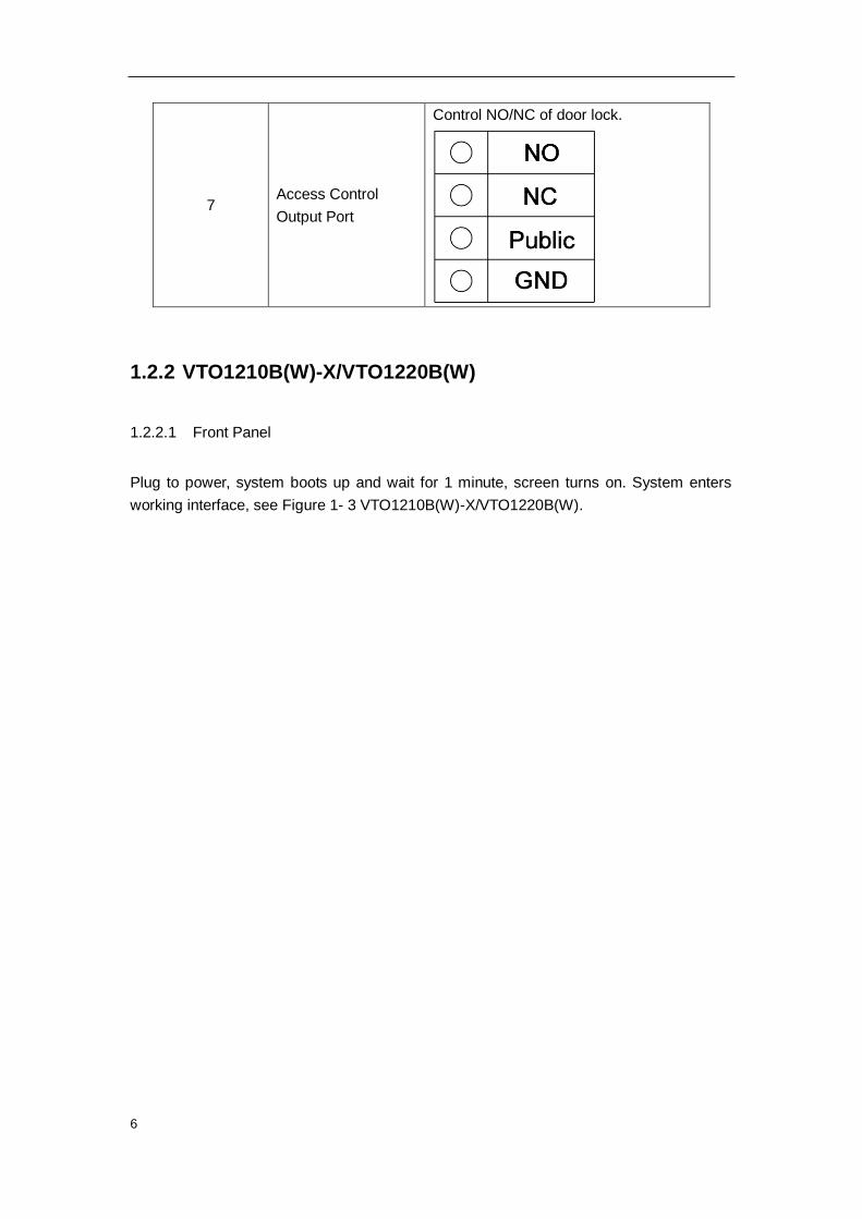
7 Access Control
Output Port
Control NO/NC of door lock.
1.2.2 VTO1210B(W)-X/VTO1220B(W)
1.2.2.1 Front Panel
Plug to power, system boots up and wait for 1 minute, screen turns on. System enters
working interface, see Figure 1- 3 VTO1210B(W)-X/VTO1220B(W).

7
Figure 1- 3 VTO1210B(W)-X/VTO1220B(W)
Please refer to the following sheet for detailed information.
SN Name Function
1 Logo Printed logo.
2 Microphone Audio input
3 Compensation Light It can compensate the camera light in
the low illumination environments.
4 Approaching
Induction It can detect approaching body.
5 Speaker Output audio

8
6 Key Panel
1. Button.
a) Backspace function. It is to delete
the previous symbol.
b) Hang up function. It is to hang up
the call.
2. Number button. Input the number 0 to
9.
3. button. When you are using the
password to open the door. Press this
button once to begin input. After you
input the password, please press it again
to complete the operation.
4. Call button. After you input the
room number, press it to begin a dial up.
5. Call center button. Press it to call
center directly.
7 Card Induction Zone Use the card to open the door.
8 LCD
Here you can view prompt information,
date, time and etc.
Note:
1. “Call: Room No. + ”. Please input
the room number first and then press the
button to dial;
2.”Call Center: Press button”. Please
press the button to call center.
3.“Password: + password + ”, If
you want to open the door via the
password, please press the button
and then input the room number and
password. Please press the button
to confirm.
9 Camera It is to monitor the video of the door.

9
1.2.2.2 Rear Panel
Figure 1- 4 VTO1210B(W)-X/VTO1220B(W) rear structure
Please refer to the following sheet for detailed information.
SN Port Name Function
1 Vandal Proof Alarm Button It can generate an alarm when there is a vandal operation.
2 Network Port Connect to the RJ45 port.
3 Access Control Input Port
Connect to signal from the door sensor, door on/off signal.
4 Power Port Connect to 12V DC power.
5 Access Control Output Port Open or close the NO/NC lock.

10
6 Analog Signal Port Connect to the analog signal of the distributor.
7 RS485 Port
Connect to RS422 or RS484 communication device.
or
1.3 VTO1210C-X
1.3.1.1 Front Panel
Plug to power, system boots up and wait for 1 minute, screen turns on. System enters
working interface, see Figure 1- 5 VTO1210C-X.

11
Figure 1- 5 VTO1210C-X
Please refer to the following sheet for detailed information.
SN Name Function
1 Logo Printed logo.
2 Microphone Audio input
3 Compensation Light It can compensate the camera light in
the low illumination environments.
4 Speaker Output audio
5 Key Panel
1. Button.
c) Backspace function. It is to delete
the previous symbol.
d) Hang up function. It is to hang up
the call.
2. Number button. Input the number 0 to
9.

12
3. button. When you are using the
password to open the door. Press this
button once to begin input. After you
input the password, please press it again
to complete the operation.
4. Call button. After you input the
room number, press it to begin a dial up.
5. Call center button. Press it to call
center directly.
6. button: In contacts interface,
press these buttons to page up and
down. They can be customized for
special function.
6 Card Induction Zone Use the card to open the door.
7 LCD
Here you can view prompt information,
date, time and etc.
Note:
1. “Call: Room No. + ”. Please input
the room number first and then press the
button to dial;
2.”Call Center: Press button”. Please
press the button to call center.
3.“Password: + password + ”, If
you want to open the door via the
password, please press the button
and then input the room number and
password. Please press the button
to confirm.
8 Camera It is to monitor the video of the door.
1.3.1.2 Rear Panel
VTO1210C-X rear panel is the same with VTO1210B(W)-X/VTO1220B(W), therefore

13
please refer to Ch 1.2.2.2.

14
2 Install VTO
Unit VTO on-site installation includes: wall embedded installation, door embedded
installation (with box/without box), standalone installation.
This chapter will introduce installation of VTO1220A/VTO1210A-X series,
VTO1210B(W)-X/VTO1220B(W) series and VTO1210C-X series.
2.1 VTO1220A/VTO1210A-X
2.1.1 Screw
Component Screw No Illustration Quantity
ST3×18 Cross recessed pan head
tapping screws –white alloy
Screw a 6
M3×16 Cross slot recessed pan head
screws- zinc black
Screw b 1
White expansion pipe ¢6×30mm None
6
2.1.2 Installation Steps
Step 1. Fix metal housing on wall with screw a.
Step 2. Fix device on the metal housing with screw b.

15
Figure 2- 1
2.1.3 Wiring
Please refer to Ch 1.2.1.2.
2.2 VTO1210B(W)-X/VTO1220B(W)
2.2.1 Screw
Component Screw No Illustration Quantity
ST3×18 Cross recessed pan head
tapping screws –white alloy
Screw a 10
M3×16 Cross slot recessed pan head
screws- zinc black
Screw b 1

16
2.2.2 Installation Steps
Step 1. Embed plastic housing into wall.
Step 2. Fix bracket on the housing with screw a.
Step 3. Fix device on the bracket with screw b.
Figure 2- 2
2.2.3 Wiring
Please refer to Ch 1.2.2.2.

17
2.3 VTO1210C-X
2.3.1 Screw
Component Illustration Quantity
M4×40 inner hex flower countersunk flat
head screws-stainless steel 4
2.3.2 Installation Steps
Step 1. Embed plastic housing into wall.
Step 2. Fix device on the bracket with screw.
Figure 2- 3
2.3.3 Wiring
Please refer to Ch 1.2.3.2.

1
3 Debug VTO
The VTO has digital system and analog system. Please read the following contents before
installing system.
Here takes VTO1220A as an example.
3.1 Digital System
3.1.1 System
See Figure 3- 1 Digital system.
Figure 3- 1 Digital system
Note:
VTO port (dual port VTO refers to Figure 1-4 no. 2 port) connects to IN port on switch.
Among switch port 1-6, select any one port to connect to VTH which allows switch to
power supply VTH.

2
3.1.2 Configure VTO
Configure VTO info, make sure there is communication among center, VTO and VTH.
Note:
Access VTO WEB config interface via PC, and please make sure PC and VTO both
connect to the Internet and are in the same segment.
Step 1. Login WEB.
Via PC remotely access VTO. In Internet Explorer, input IP address of the VTO
and enters VTO WEB login page.
You must input username and password in order to login WEB main interface.
Click on login.
Default username: admin
Default password: admin.
Step 2. Set device info.
a) Select System Config>Local Config.
b) Set system type to digital (Tcp/IP), video format is WVGA, and set frame rate
according to your condition. Click on OK. See Figure 3- 2.
Figure 3- 2
Step 3. Set LAN.
a) In page, select System Config>LAN Config, enter LAN Config interface.
b) The default config can ensure VTO and VTH are connected. If you want to
configure center, the setup shall match setup in center and check register to the
MGT center in LAN Config. See Figure 3- 3.

3
Figure 3- 3
Step 4. Add digital VTH.
a) In page, select System Config>VTH Management>Indoor Management.
b) Click on Add to add VTH.
c) Click on OK.
See Figure 3- 4.
Figure 3- 4
Note:
If you want to add many room no., you can modify unit floor and rooms on a floor in
Step 2 to batch add room no.
Parameter with * are mandatory.
Step 5. Set network info.
a) In page, select System Config>Network Config.
b) Set VTO IP address, subnet mask and default gateway. After you are dome,
WEB page will reboot and go to the new set page. See Figure 3- 5.

4
Figure 3- 5
3.1.3 Digital VTH
Enters digital VTH system settings-project setting, input VTH project password 002236.
According to VTO config, input room no.; in network config, set VTH IP, subnet mask,
gateway and etc; in network terminal, fill in VTO IP, enable and click on OK.
Note:
Please refer to corresponding VTH user’s manual.
3.1.4 Result Test
On VTH, press monitor button to monitor VTH video.
On VTO, press room no. + to call correspinding VTH.
3.2 Analog System
3.2.1 System
See Figure 3- 6 Analog System.

5
Figure 3- 6 Analog System
Note:
VTO analog signal port (see Figure 1-2 and 1-4) connects to allocator IN port. Select any
port of allocator to connect to VTH which allows allocator to power supply VTH.
A-X connects to analog signal port network cable according to cable color, from down to
up are: white-blue, blue, NA, NA, white-green, green, white-brown, and brown.
3.2.2 Configure VTO
Configure VTO info, ensure VTO and MGT center, VTO and VTH are connected.
Step 1. Login WEB.
Via PC remotely access VTO. In Internet Explorer, input VTO IP to enter VTO
WEB login page. Input account: admin; password: admin. Click on Login
Step 2. Set device info.
a) In page, select System Config>Local Config.
b) Set system type to analogue, video format to D1 and set frame rate according to
environment. Click on OK. See Figure 3- 7.
6
Figure 3- 7
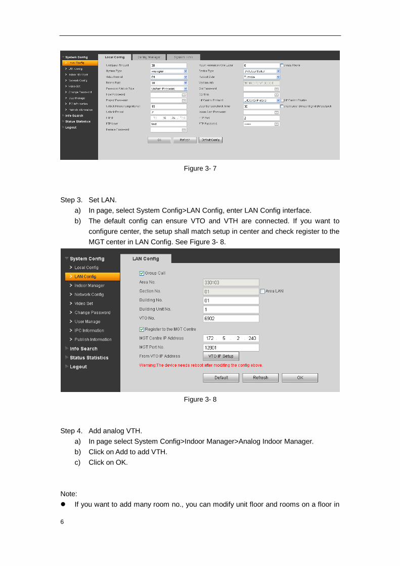
Step 3. Set LAN.
a) In page, select System Config>LAN Config, enter LAN Config interface.
b) The default config can ensure VTO and VTH are connected. If you want to
configure center, the setup shall match setup in center and check register to the
MGT center in LAN Config. See Figure 3- 8.
Figure 3- 8
Step 4. Add analog VTH.
a) In page select System Config>Indoor Manager>Analog Indoor Manager.
b) Click on Add to add VTH.
c) Click on OK.
Note:
If you want to add many room no., you can modify unit floor and rooms on a floor in

7
Step 2 to batch add room no.
Parameter with * are mandatory.
Step 5. Set network info.
a) In page, select System Config>Network Config.
b) Set VTO IP address, subnet mask and default gateway. After you are dome,
WEB page will reboot and go to the new set page. See Figure 3- 9.
Figure 3- 9
Note:
Please refer to Ch 5.
3.2.3 Analog VTH
4.3 inch VTH: plug it to power and long press call button, wait until it VTH enters room no.
set page. Press SOS button to select digit, and switch number and confirm via call button.
Then, VTH will reboot.
7 inch VTH: plug it to power and long press call button, wait until it VTH enters room no.
set page. Press SOS button to select digit, and switch number and confirm via call button.
Then, VTH will reboot.
Note: For more than one VTH, please set one by one!
For more config, please refer to VTO user’s manual.

8
3.2.4
On VTH, press monitor button to monitor VTH video.
On VTO, press room no. + to call correspinding VTH.

1
4 Basic Functions
4.1 Call
Under standby status (Figure 1-1, Figure 1-2), press or button, this VTO will call
center. The video door phone begins when the port picks up. During the whole process,
you can press the button or to end current talk and return to the standby
interface.
Under standby status, enter room no. or press or to select room no. in contacts,
and press or to call VTH. The video door phone begins when the VTH picks up.
During the whole process, you can press the button or to end current talk and
return to the standby interface.
4.2 Modify Local Config
4.2.1 Enter Project Settings Interface
In the standby status, press or , input password as 888888 and then press or
to enter installation setup interface. Select up/down via button 2 and 8, press or
to enter sub-interface.
4.2.2 Modify IP, Gateway and Subnet Mask
In project settings --- IP setup interface, select up/down/left/right via button 2,8,4,6, press
or to enter/exit IP modification status. When you finish, press or to exit
modification interface.

2
4.2.3 Modify Volume Config
In volume interface, adjust volume via button 4 and 6. When you finish, press or
to exit modification interface.
4.3 Issue Card
In card issuing interface, select to issue card with parent card or password via button 2
and 8. Press or to enter sub-interface.
Issue with parent card: Under issuing card with parent card interface, fill in room no. of the
card to be authorized, and swipe it. When it says the card has been authorized
successfully, press or to exit.
Issue with password: Under issuing card with password interface, enter issuing password
002236, press or to enter, fill in room no. of the card to be authorized, and swipe
it. When it says the card has been authorized successfully, press or to exit.
4.4 Password Function
4.4.1 Unlock from VTH and Center
During calling, talk and monitoring statuses, the center or the VTH can open the door lock
of the device remotely. System returns to the standby interface after phone hangs up or
the countdown is complete.
4.4.2 Unlock from Local
VTO WEB page – A&C Manager—Password Unlock Type, select either uniform password
or self password.
Uniform password: In standby interface, press or , input default password:
123456, press or to unlock. Defualt password can be changed in A&C Manager
interface.

3
Self password: n standby interface, press or , input 4-digit room no. + default
password: 123456, press or to unlock. For example, to unlock room 101, you
shall input: #0101123456#. Defualt password can be changed in A&C Manager interface.
4.4.3 Unlock via IC card
The door is open after you swipe IC card and the card passed the authentication and
station verification.
4.5 VTO Web Function
4.5.1 Web Login
Access VTO from PC, input the IP address of VDP in your explorer to enter the web login
page. Input username: admin and password: admin, then you can enter its web page
where you can configure the VTO. Please refer to the following chapter for details.

4
5 Web Function
5.1 Login
In Internet Explorer, input VTO IP address as in Figure 5- 1.
Figure 5- 1
You must input username and password in order to login WEB main interface.
Default username: admin
Default password: admin.
After you login, you will see 4 major settings: system, info search, status statistics, and
Logout.
WEB function supports VTO1220A, VTO1220B, VTO1210A-X, VTO1210B(W)-X and
VTO1210C-X. WEB pages may be different for different models.
5.2 System Config
System Config includes Local Config, LAN Config, Indoor Manager, Network Config,
Video Set, Change Password, User Manage, IPC Information, Publish Information.

5
5.2.1 Local Config
5.2.1.1 Local Config
In page, select System Config>Local Config. Set parameter, and click on OK. See Figure
5- 2.
Figure 5- 2
Parameter Note
Device Type Display device type.
Video Format Set collected video format by camera, including:WVGA, D1.
WVGA resolution si 800×480;D1 resolution is 704×576.
Reboot Date In set date, device will reboot.
Frame Rate Set NTSC to 30 and PAL to 25.
Password Unlock
Type
Includes self password and uniform password.
Project Password Password to enter project setting page. Default is 888888.
Unlock
Responding
Interval
Unlock, after this interval device will respond again. Unit is second.
Door Sensor
Check Time
Only use door sensor, check Check Door Sensor Signal Before Lock and
set door sensor check time to enable it.
When unlock time out, door sensor will alarm. Check Door
Sensor Signal
Before Lock
Unlock Period Time that door lock remains unlocked. Unit is second.
Issue Card
Password
Default is 123456.
FTP IP, FTP port,
FTP user, FTP
password.
FTP server is used to store picture taken when swipe card at VTO. User can
log in FTP to get these pictures.

6
Menace Password Set menace password. Default is 654321.
Default Config Set all parameters to default status.
Note:
Every half an hour, VTO will automatically saves card no. and VTH info on
VTO.
5.2.1.2 Config Manager
In page, select System Config>Local Config>Config Manager. See Figure 5- 3.
Figure 5- 3
Paraemter Note
Restore Backup Check card info, vth into, and click on Restore Backup to restore default
card info and vth info.
Export Config Export config file(Config.backup).
Import Config Import config file.
Default All Device all parameters will be restored to default.
Warning:
Please back up first before perform this operation.
Note:
Every half an hour, VTO will automatically saves card no. and VTH info on VTO.
Therefore, is you want to restore VTH information or card no., please do so within
half an hour after these information were changed.
5.2.1.3 System Time
In page, select System Config>Local Config>System Time.
Set date format, time format and system time. Click on OK as complete setup. Or click on
Sync PC to make VTO time same as PC time. See Figure 5- 4.

7
Figure 5- 4
5.2.2 LAN Config
In page, select System Config>LAN Config.
Default setting is enough if you just want networking between VTO and VTH, but if you
want to set the center, you need to change default settings to be identical with center info.
You also need to check box register to MGT center.
If you successfully set center, you may call center by pressing call center button at lower
left corner on VTO. See Figure 5- 5.
Figure 5- 5
5.2.3 Indoor Manager
Indoor Station Manager mainly includes adding digital/analog VTH, deleting VTH and
editing VTH user. VTO1210A-X and VTO1210B-X have digital and analog indoor station

8
manager. VTO1220A only has digital indoor station manager.
5.2.3.1 Add Digital/Analog VTH
Step 1. In page, select System Config>Indoor Manager>Digital Indoor Station (or Analog
Indoor Station.
Step 2. Click on Add.
Step 3. Fill in VTH information, click on OK.
See Figure 5- 6 for example as digital VTH.
Figure 5- 6
Note:
Parameters with * are mandatory.
Parameter Note Setup
VTH short
no.
VTH short no. is room no.,
composed of 4 digits of number.
For example, 1101. “11” means
floor 11 while “01” means room
no.
Note:
VTH short no. first two digits
range is 01~99. Last two digits
range is 01~16.
IP
Address
Add VTH IP address. Example:172.27.0.62.
Short No. Analog VTH room no. Example: room no. is 1502, the
allocator address is 15, and
port no. is 2.
Allocator
Address
Allocator dial-up address, range
1~99, write into program and
will not be changes in general.

9
Allocator
Port
Allocator corresponding ports
no. 4-ch allocator port is 1~4,
8-ch allocator port is 1~8.
5.2.3.2 Modify Digital/Analog VTH
Click on , in pop-up page, modify VTH information.
For digital VTH, you can only modify name information.
For analog VTH, you can only modify name, allocator address and port.
5.2.3.3 Delete Digital/Analog VTH
Click on to delete digital/analog VTH.
5.2.4 Allocator Manager
In page, select System Config>Allocator Manager.
You can view allocator ID, MAC address and etc.
5.2.5 Network Config
In page, select System Config>Network Config.
Set VTO IP network parameter, you can set VTO IP address, subnet mask and default
gateway. After you modify IP address, WEB page will reboot and go to the new set page.
See Figure 5- 7.
Figure 5- 7

10
5.2.6 Video Set
In page, select System Config>Video Set.
When you see “w_no_plugins” on screen, please click on it and install control unit
according to introduction. See Figure 5- 8.
Figure 5- 8
Parameter Note
Motion Detection When detect body approaching VTO, it will automatically turn on
indicator.
Brightness, Contrast, HUE
and Saturation
Adjust camera video.
Gain Mode Auto mode: system automatically adjusts.
Scene Mode Includes: disabled, automatic, sunny and night.
Day/Night Mode Includes: colorful, automatic, black white.
Backlight Mode Includes: close, backlight, wide dynamic, and inhibition.
Mirror Horizontally flip video.
Flip Vertically flip video.
VTO MIC Volume, VTO
Beep Volume
Adjust VTO MIC and beep volume.
Analog MIC Volume, Analog
Beep Volume
Adjust analog MIC and beep volume.
Default Restore all parameter in video set tab to default.
Unlock Click on unlock to remotely unlock door lock.
11
5.2.7 Change Password
In page, select System Config>Change Password.
In Change Password interface, you can change WEB login password of VTO. You must
input old password, new password and confirm new password. Click on OK button to
save.
5.2.8 User Manage
Only when you login as admin, you can add, modify, delete and view user information.
System currently supports two types of user:
Admin has higher rights to view, edit, delete system configuration right.
User can only view system configuration.
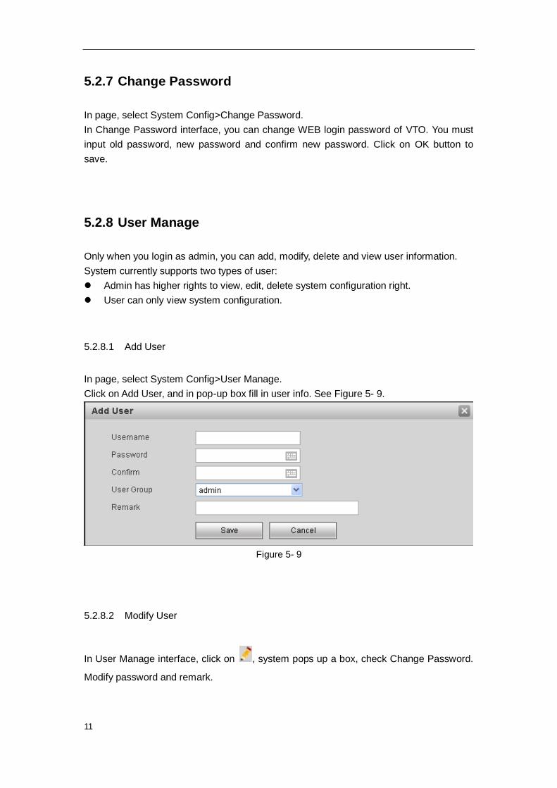
5.2.8.1 Add User
In page, select System Config>User Manage.
Click on Add User, and in pop-up box fill in user info. See Figure 5- 9.
Figure 5- 9
5.2.8.2 Modify User
In User Manage interface, click on , system pops up a box, check Change Password.
Modify password and remark.

12
5.2.8.3 Delete User
In User Manage interface, click on to delete user.
5.2.9 IPC Information
In page, select System Config>IPC Information.
You can view IPC video via the VTH.
In IPC Information interface, click on , system pops up a box, fill in IPC information.
See Figure 5- 10.
Figure 5- 10
5.2.10 Publish Information
In Publish Information page, you can send publish information and view historical
information.
5.2.10.1 Send Info
In page, select System Config>Publish Information>Send Info.
See Figure 5- 11. Click on Send.

13
Figure 5- 11
5.2.10.2 History Info
In page, select System Config>Publish Information>History Info.
You can view historical information, click on to delete ifnormation.
5.3 Info Search
You can view call record, alarm record and swiping card record.
5.3.1 Call Record
In page, select Info Search>Call History.
You can search VTO call records and the system can store up to 1124 records.
Click on Export Record to save record to local. See Figure 5- 12.
Figure 5- 12

14
5.3.2 Alarm Record
In page, select Info Search>Alarm Record.
You can search VTO alarm records and the system can store up to 1124 records.
Click on Export Record to save record to local. See Figure 5- 13.
Figure 5- 13
5.3.3 Swiping Card Record
In page, select Info Search>Swiping Card Record.
You can search VTO card swiping records and the system can store up to 1124 records.
Click on Export Record to save record to local. See Figure 5- 14.
Figure 5- 14
15
5.4 Status Statistics
In page, select Status Statistics>VTH Status.
You can view connection status of VTH. See Figure 5- 15.
Figure 5- 15
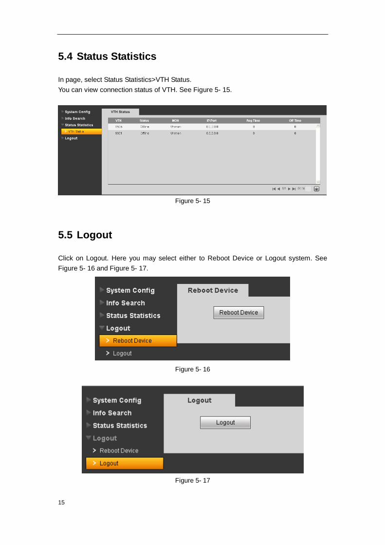
5.5 Logout
Click on Logout. Here you may select either to Reboot Device or Logout system. See
Figure 5- 16 and Figure 5- 17.
Figure 5- 16
Figure 5- 17

16
Appendix 1 Specifications
Model VTO1220A VTO1220B(W) VTO1210A-X VTO1210B(W)-X VTO1210C-X
OS
Main Processor Embedded micro processor
OS Embedded LINUX OS
Video
Video Compression Standard H.264
Input/Approaching Induction 1.3 megapixel CMOS camera
Back Light Support
Auto Light Compensation Support
Audio
Input Microphone
Output Built-in speaker
Bidirectional Talk Support dual-way bidirectional talk
Display
LCD Dimensions 3.5-inch TFT screen 3-inch STN
screen 3-inch STN screen
Resolution 320*240 128*64 128*64
Operation Mode
Input
Digital
keyboard
Touch
keyboard
Digital
keyboard
Touch
keyboard
Digital
keyboard
Card Built-in IC card induction reader
Approaching Induction
Body Approaching IR, about 1 meter
Alarm
Vandal proof Support
Access Control
NO/NC Output Support
Door on/off Button Support
Door Status Detect Support
Network
Ethernet 10M/100Mbps Self-adaptive
Network Protocol TCP/IP
Storage
Memory 128MB
Others

17
Power DC 12V
Power Consumption Standby≤1W ;work≤10W
Working Environments -40℃~+60℃
10~95%RH
Water Proof VTO1212B(W)-X/VTO1220B Water proof level:IP65;
VTO1210A-X/VTO1210C-X Water proof level: IP53

18
Note:
This manual is for reference only. Slight difference may be found in user
interface.
All the designs and software here are subject to change without prior written
notice.
All trademarks and registered trademarks are the properties of their respective
owners.
If there is any uncertainty or controversy, please refer to the final explanation of
us.
Please visit our website or contact your local service engineer for more
information.