vs0201 / vs0401para instalar el conmutador, véase el diagrama de instalación cuando vaya a...
TRANSCRIPT
RequirementsSource DeviceThe following equipment must be installed on the source device or computer that acts as a source of VGA/Audio content:• VGA video card with HDB-15 connector• Audio source with stereo output
Display Device• A VGA, SVGA, UXGA, WUXGA or multisync monitor or multimedia
projector with an HDB-15 connector• Stereo audio speakers
Cables• 1 VGA/Audio cable for each source device you will be connecting• 1 VGA/Audio cable for your display device
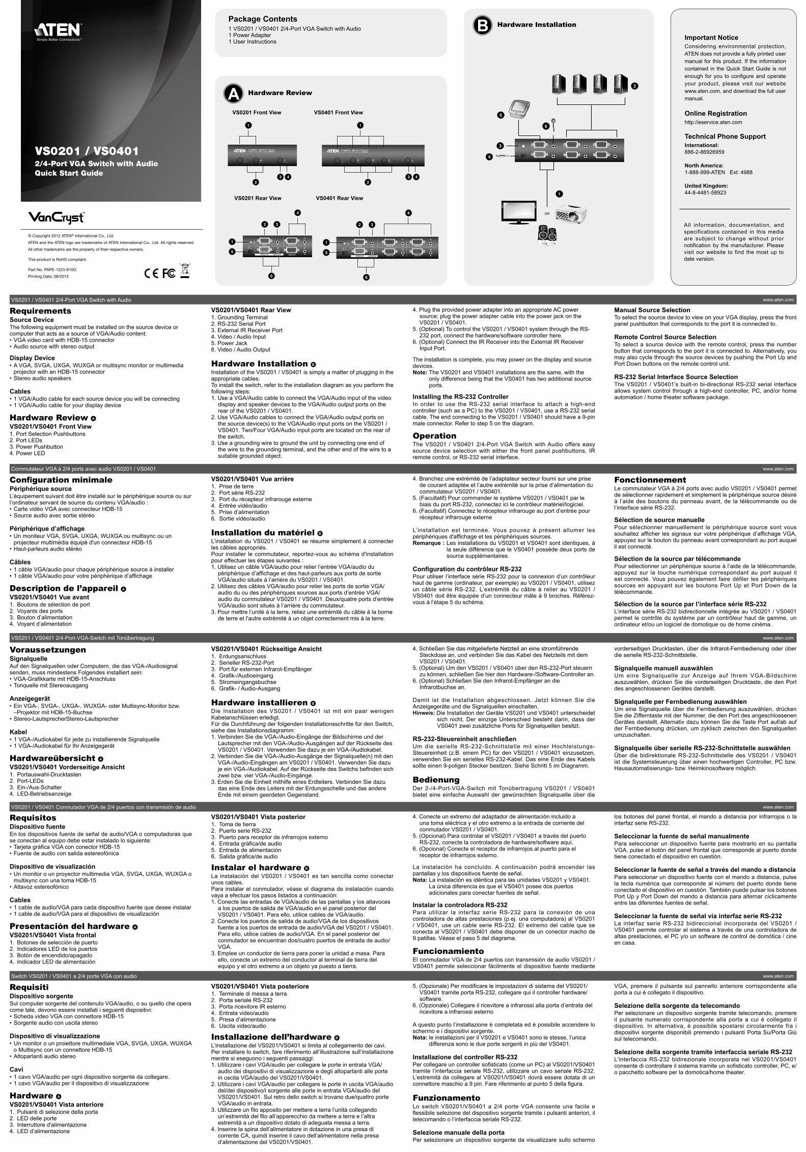
Hardware Review A VS0201/VS0401 Front View1. Port Selection Pushbuttons2. Port LEDs3. Power Pushbutton4. Power LED
Configuration minimalePériphérique sourceL’équipement suivant doit être installé sur le périphérique source ou sur l’ordinateur servant de source du contenu VGA/audio :• Carte vidéo VGA avec connecteur HDB-15• Source audio avec sortie stéréo
Périphérique d’affichage• Un moniteur VGA, SVGA, UXGA, WUXGA ou multisync ou un
projecteur multimédia équipé d'un connecteur HDB-15• Haut-parleurs audio stéréo
Câbles• 1 câble VGA/audio pour chaque périphérique source à installer• 1 câble VGA/audio pour votre périphérique d’affichage
Description de l’appareil A VS0201/VS0401 Vue avant1. Boutons de sélection de port2. Voyants des ports3. Bouton d’alimentation4. Voyant d’alimentation
VoraussetzungenSignalquelleAuf den Signalquellen oder Computern, die das VGA-/Audiosignal senden, muss mindestens Folgendes installiert sein:• VGA-Grafikkarte mit HDB-15-Anschluss• Tonquelle mit Stereoausgang
Anzeigegerät• Ein VGA-, SVGA-, UXGA-, WUXGA- oder Multisync-Monitor bzw.
–Projektor mit HDB-15-Buchse• Stereo-LautsprecherStereo-Lautsprecher
Kabel• 1 VGA-/Audiokabel für jede zu installierende Signalquelle• 1 VGA-/Audiokabel für Ihr Anzeigegerät
Hardwareübersicht A VS0201/VS0401 Vorderseitige Ansicht1. Portauswahl-Drucktasten2. Port-LEDs3. Ein-/Aus-Schalter4. LED-Betriebsanzeige
RequisitosDispositivo fuenteEn los dispositivos fuente de señal de audio/VGA o computadoras que se conectan al equipo debe estar instalado lo siguiente:• Tarjeta gráfica VGA con conector HDB-15• Fuente de audio con salida estereofónica
Dispositivo de visualización• Un monitor o un proyector multimedia VGA, SVGA, UXGA, WUXGA o
multisync con una toma HDB-15• Altavoz estereofónico
Cables• 1 cable de audio/VGA para cada dispositivo fuente que desee instalar• 1 cable de audio/VGA para el dispositivo de visualización
Presentación del hardware A VS0201/VS0401 Vista frontal1. Botones de selección de puerto2. Indicadores LED de los puertos3. Botón de encendido/apagado4. Indicador LED de alimentación
RequisitiDispositivo sorgenteSul computer sorgente del contenuto VGA/audio, o su quello che opera come tale, devono essere installati i seguenti dispositivi:• Scheda video VGA con connettore HDB-15• Sorgente audio con uscita stereo
Dispositivo di visualizzazione• Un monitor o un proiettore multimediale VGA, SVGA, UXGA, WUXGA
o Multisync con un connettore HDB-15• Altoparlanti audio stereo
Cavi• 1 cavo VGA/audio per ogni dispositivo sorgente da collegare.• 1 cavo VGA/audio per il dispositivo di visualizzazione
Hardware A VS0201/VS0401 Vista anteriore1. Pulsanti di selezione della porta2. LED delle porte3. Interruttore d'alimentazione4. LED d’alimentazione
VS0201/VS0401 Rear View1. Grounding Terminal2. RS-232 Serial Port3. External IR Receiver Port4. Video / Audio Input5. Power Jack6. Video / Audio Output
Hardware Installation B Installation of the VS0201 / VS0401 is simply a matter of plugging in the appropriate cables.To install the switch, refer to the installation diagram as you perform the following steps:1. Use a VGA/Audio cable to connect the VGA/Audio input of the video
display and speaker devices to the VGA/Audio output ports on the rear of the VS0201 / VS0401.
2. Use VGA/Audio cables to connect the VGA/Audio output ports on the source device(s) to the VGA/Audio input ports on the VS0201 / VS0401. Two/Four VGA/Audio input ports are located on the rear of the switch.
3. Use a grounding wire to ground the unit by connecting one end of the wire to the grounding terminal, and the other end of the wire to a suitable grounded object.
VS0201/VS0401 Vue arrière1. Prise de terre2. Port série RS-2323. Port du récepteur infrarouge externe4. Entrée vidéo/audio5. Prise d’alimentation6. Sortie vidéo/audio
Installation du matériel B L’installation du VS0201 / VS0401 se résume simplement à connecter les câbles appropriés.Pour installer le commutateur, reportez-vous au schéma d'installation pour effectuer les étapes suivantes :1. Utilisez un câble VGA/audio pour relier l’entrée VGA/audio du
périphérique d’affichage et des haut-parleurs aux ports de sortie VGA/audio situés à l’arrière du VS0201 / VS0401.
2. Utilisez des câbles VGA/audio pour relier les ports de sortie VGA/audio du ou des périphériques sources aux ports d’entrée VGA/audio du commutateur VS0201 / VS0401. Deux/quatre ports d’entrée VGA/audio sont situés à l’arrière du commutateur.
3. Pour mettre l’unité à la terre, reliez une extrémité du câble à la borne de terre et l'autre extrémité à un objet correctement mis à la terre.
VS0201/VS0401 Rückseitige Ansicht1. Erdungsanschluss2. Serieller RS-232-Port3. Port für externen Infrarot-Empfänger4. Grafik-/Audioeingang5. Stromeingangsbuchse6. Grafik- / Audio-Ausgang
Hardware installieren B Die Installation des VS0201 / VS0401 ist mit ein paar wenigen Kabelanschlüssen erledigt.Für die Durchführung der folgenden Installationsschritte für den Switch, siehe das Installationsdiagramm:1. Verbinden Sie die VGA-/Audio-Eingänge der Bildschirme und der
Lautsprecher mit den VGA-/Audio-Ausgängen auf der Rückseite des VS0201 / VS0401. Verwenden Sie dazu je ein VGA-/Audiokabel.
2. Verbinden Sie die VGA-/Audio-Ausgänge der Signalquelle(n) mit den VGA-/Audio-Eingängen am VS0201 / VS0401. Verwenden Sie dazu je ein VGA-/Audiokabel. Auf der Rückseite des Switchs befinden sich zwei bzw. vier VGA-/Audio-Eingänge.
3. Erden Sie die Einheit mithilfe eines Erdleiters. Verbinden Sie dazu das eine Ende des Leiters mit der Erdungsschelle und das andere Ende mit einem geerdeten Gegenstand.
VS0201/VS0401 Vista posterior1. Toma de tierra2. Puerto serie RS-2323. Puerto para receptor de infrarrojos externo4. Entrada gráfica/de audio5. Entrada de alimentación6. Salida gráfica/de audio
Instalar el hardware B La instalación del VS0201 / VS0401 es tan sencilla como conectar unos cables.Para instalar el conmutador, véase el diagrama de instalación cuando vaya a efectuar los pasos listados a continuación:1. Conecte las entradas de VGA/audio de las pantallas y los altavoces
a los puertos de salida de VGA/audio en el panel posterior del VS0201 / VS0401. Para ello, utilice cables de VGA/audio.
2. Conecte los puertos de salida de audio/VGA de los dispositivos fuente a los puertos de entrada de audio/VGA del VS0201 / VS0401. Para ello, utilice cables de audio/VGA. En el panel posterior del conmutador se encuentran dos/cuatro puertos de entrada de audio/VGA.
3. Emplee un conductor de tierra para poner la unidad a masa. Para ello, conecte un extremo del conductor al terminal de tierra del equipo y el otro extremo a un objeto ya puesto a tierra.
VS0201/VS0401 Vista posteriore1. Terminale di messa a terra2. Porta seriale RS-2323. Porta ricevitore IR esterno4. Entrata video/audio5. Presa d’alimentazione6. Uscita video/audio
Installazione dell’hardware B L’installazione del VS0201/VS0401 si limita al collegamento dei cavi.Per installare lo switch, fare riferimento all’illustrazione sull’installazione mentre si eseguono i seguenti passaggi:1. Utilizzare i cavi VGA/audio per collegare le porte in entrata VGA/
audio dei dispositivi di visualizzazione e degli altoparlanti alle porte in uscita VGA/audio del VS0201/VS0401.
2. Utilizzare i cavi VGA/audio per collegare le porte in uscita VGA/audio del/dei dispositivo/i sorgente alle porte in entrata VGA/audio del VS0201/VS0401. Sul retro dello switch si trovano due/quattro porte VGA/audio in entrata.
3. Utilizzare un filo apposito per mettere a terra l’unità collegando un’estremità del filo all’apparecchio da mettere a terra e l’altra estremità a un dispositivo dotato di adeguata messa a terra.
4. Inserire la spina dell’alimentatore in dotazione in una presa di corrente CA, quindi inserire il cavo dell’alimentatore nella presa d’alimentazione del VS0201/VS0401.
4. Plug the provided power adapter into an appropriate AC power source; plug the power adapter cable into the power jack on the VS0201 / VS0401.
5. (Optional) To control the VS0201 / VS0401 system through the RS-232 port, connect the hardware/software controller here.
6. (Optional) Connect the IR Receiver into the External IR Receiver Input Port.
The installation is complete, you may power on the display and source devices.Note: The VS0201 and VS0401 installations are the same, with the
only difference being that the VS0401 has two additional source ports.
Installing the RS-232 ControllerIn order to use the RS-232 serial interface to attach a high-end controller (such as a PC) to the VS0201 / VS0401, use a RS-232 serial cable. The end connecting to the VS0201 / VS0401 should have a 9-pin male connector. Refer to step 5 on the diagram.
OperationThe VS0201 / VS0401 2/4-Port VGA Switch with Audio offers easy source device selection with either the front panel pushbuttons, IR remote control, or RS-232 serial interface.
4. Branchez une extrémité de l’adaptateur secteur fourni sur une prise de courant adaptée et l’autre extrémité sur la prise d’alimentation du commutateur VS0201 / VS0401.
5. (Facultatif) Pour commander le système VS0201 / VS0401 par le biais du port RS-232, connectez ici le contrôleur matériel/logiciel.
6. (Facultatif) Connectez le récepteur infrarouge au port d’entrée pour récepteur infrarouge externe
L’installation est terminée. Vous pouvez à présent allumer les périphériques d'affichage et les périphériques sources.Remarque : Les installations du VS0201 et VS0401 sont identiques, à
la seule différence que le VS0401 possède deux ports de source supplémentaires.
Configuration du contrôleur RS-232Pour utiliser l’interface série RS-232 pour la connexion d’un contrôleur haut de gamme (ordinateur, par exemple) au VS0201 / VS0401, utilisez un câble série RS-232. L’extrémité du câble à relier au VS0201 / VS0401 doit être équipée d’un connecteur mâle à 9 broches. Référez-vous à l’étape 5 du schéma.
4. Schließen Sie das mitgelieferte Netzteil an eine stromführende Steckdose an, und verbinden Sie das Kabel des Netzteils mit dem VS0201 / VS0401.
5. (Optional) Um den VS0201 / VS0401 über den RS-232-Port steuern zu können, schließen Sie hier den Hardware-/Software-Controller an.
6. (Optional) Schließen Sie den Infrarot-Empfänger an die Infrarotbuchse an.
Damit ist die Installation abgeschlossen. Jetzt können Sie die Anzeigegeräte und die Signalquellen einschalten.Hinweis: Die Installation der Geräte VS0201 und VS0401 unterscheidet
sich nicht. Der einzige Unterschied besteht darin, dass der VS0401 zwei zusätzliche Ports für Signalquellen besitzt.
RS-232-Steuereinheit anschließenUm die serielle RS-232-Schnittstelle mit einer Hochleistungs-Steuereinheit (z.B. einem PC) für den VS0201 / VS0401 einzusetzen, verwenden Sie ein serielles RS-232-Kabel. Das eine Ende des Kabels sollte einen 9-poligen Stecker besitzen. Siehe Schritt 5 im Diagramm.
BedienungDer 2-/4-Port-VGA-Switch mit Tonübertragung VS0201 / VS0401 bietet eine einfache Auswahl der gewünschten Signalquelle über die
4. Conecte un extremo del adaptador de alimentación incluido a una toma eléctrica y el otro extremo a la entrada de corriente del conmutador VS0201 / VS0401.
5. (Opcional) Para controlar el VS0201 / VS0401 a través del puerto RS-232, conecte la controladora de hardware/software aquí.
6. (Opcional) Conecte el receptor de infrarrojos al puerto para el receptor de infrarrojos externo.
La instalación ha concluido. A continuación podrá encender las pantallas y los dispositivos fuente de señal.Nota: La instalación es idéntica para las unidades VS0201 y VS0401.
La única diferencia es que el VS0401 posee dos puertos adicionales para conectar fuentes de señal.
Instalar la controladora RS-232Para utilizar la interfaz serie RS-232 para la conexión de una controladora de altas prestaciones (p.ej. una computadora) al VS0201 / VS0401, use un cable serie RS-232. El extremo del cable que se conecta al VS0201 / VS0401 debe disponer de un conector macho de 9 patillas. Véase el paso 5 del diagrama.
FuncionamientoEl conmutador VGA de 2/4 puertos con transmisión de audio VS0201 / VS0401 permite seleccionar fácilmente el dispositivo fuente mediante
5. (Opzionale) Per modificare le impostazioni di sistema del VS0201/VS0401 tramite porta RS-232, collegare qui il controller hardware/software.
6. (Opzionale) Collegare il ricevitore a infrarossi alla porta d’entrata del ricevitore a infrarossi esterno
A questo punto l’installazione è completata ed è possibile accendere lo schermo e i dispositivi sorgente.Nota: le installazioni per il VS0201 e VS0401 sono le stesse, l’unica
differenza sono le due porte sorgenti in più del VS0401.
Installazione del controller RS-232Per collegare un controller sofisticato (come un PC) al VS0201/VS0401 tramite l’interfaccia seriale RS-232, utilizzare un cavo seriale RS-232. L’estremità da collegare al VS0201/VS0401 dovrà essere dotata di un connettore maschio a 9 pin. Fare riferimento al punto 5 della figura.
FunzionamentoLo switch VS0201/VS0401 a 2/4 porte VGA consente una facile e flessibile selezione del dispositivo sorgente tramite i pulsanti anteriori, il telecomando o l’interfaccia seriale RS-232.
Selezione manuale della portaPer selezionare un dispositivo sorgente da visualizzare sullo schermo
Manual Source SelectionTo select the source device to view on your VGA display, press the front panel pushbutton that corresponds to the port it is connected to.
Remote Control Source SelectionTo select a source device with the remote control, press the number button that corresponds to the port it is connected to. Alternatively, you may also cycle through the source devices by pushing the Port Up and Port Down buttons on the remote control unit.
RS-232 Serial Interface Source Selection The VS0201 / VS0401’s built-in bi-directional RS-232 serial interface allows system control through a high-end controller, PC, and/or home automation / home theater software package.
FonctionnementLe commutateur VGA à 2/4 ports avec audio VS0201 / VS0401 permet de sélectionner rapidement et simplement le périphérique source désiré à l’aide des boutons du panneau avant, de la télécommande ou de l’interface série RS-232.
Sélection de source manuellePour sélectionner manuellement le périphérique source sont vous souhaitez afficher les signaux sur votre périphérique d’affichage VGA, appuyez sur le bouton du panneau avant correspondant au port auquel il est connecté.
Sélection de la source par télécommandePour sélectionner un périphérique source à l’aide de la télécommande, appuyez sur la touche numérique correspondant au port auquel il est connecté. Vous pouvez également faire défiler les périphériques sources en appuyant sur les boutons Port Up et Port Down de la télécommande.
Sélection de la source par l’interface série RS-232 L’interface série RS-232 bidirectionnelle intégrée au VS0201 / VS0401 permet le contrôle du système par un contrôleur haut de gamme, un ordinateur et/ou un logiciel de domotique ou de home cinéma.
vorderseitigen Drucktasten, über die Infrarot-Fernbedienung oder über die serielle RS-232-Schnittstelle.
Signalquelle manuell auswählenUm eine Signalquelle zur Anzeige auf Ihrem VGA-Bildschirm auszuwählen, drücken Sie die vorderseitigen Drucktaste, die den Port des angeschlossenen Gerätes darstellt.
Signalquelle per Fernbedienung auswählenUm eine Signalquelle über die Fernbedienung auszuwählen, drücken Sie die Zifferntaste mit der Nummer, die den Port des angeschlossenen Gerätes darstellt. Alternativ dazu können Sie die Taste Port auf/ab auf der Fernbedienung drücken, um zyklisch zwischen den Signalquellen umzuschalten.
Signalquelle über serielle RS-232-Schnittstelle auswählen Über die bidirektionale RS-232-Schnittstelle des VS0201 / VS0401 ist die Systemsteuerung über einen hochwertigen Controller, PC bzw. Hausautomatisierungs- bzw. Heimkinosoftware möglich.
los botones del panel frontal, el mando a distancia por infrarrojos o la interfaz serie RS-232.
Seleccionar la fuente de señal manualmentePara seleccionar un dispositivo fuente para mostrarlo en su pantalla VGA, pulse el botón del panel frontal que corresponde al puerto donde tiene conectado el dispositivo en cuestión.
Seleccionar la fuente de señal a través del mando a distanciaPara seleccionar un dispositivo fuente con el mando a distancia, pulse la tecla numérica que corresponde al número del puerto donde tiene conectado el dispositivo en cuestión. También puede pulsar los botones Port Up y Port Down del mando a distancia para alternar cíclicamente entre las diferentes fuentes de señal.
Seleccionar la fuente de señal vía interfaz serie RS-232 La interfaz serie RS-232 bidireccional incorporada del VS0201 / VS0401 permite controlar el sistema a través de una controladora de altas prestaciones, el PC y/o un software de control de domótica / cine en casa.
VGA, premere il pulsante sul pannello anteriore corrispondente alla porta a cui è collegato il dispositivo.
Selezione della sorgente da telecomandoPer selezionare un dispositivo sorgente tramite telecomando, premere il pulsante numerato corrispondente alla porta a cui è collegato il dispositivo. In alternativa, è possibile spostarsi circolarmente fra i dispositivi sorgente disponibili premendo i pulsanti Porta Su/Porta Giù sul telecomando.
Selezione della sorgente tramite interfaccia seriale RS-232 L'interfaccia RS-232 bidirezionale incorporata nel VS0201/VS0401 consente di controllare il sistema tramite un sofisticato controller, PC, e/o pacchetto software per la domotica/home theater.
BPackage Contents1 VS0201 / VS0401 2/4-Port VGA Switch with Audio1 Power Adapter1 User Instructions Important Notice
Considering environmental protection, ATEN does not provide a fully printed user manual for this product. If the information contained in the Quick Start Guide is not enough for you to configure and operate your product, please visit our website www.aten.com, and download the full user manual.
Online Registrationhttp://eservice.aten.com
Technical Phone SupportInternational:886-2-86926959
North America:1-888-999-ATEN Ext: 4988
United Kingdom:44-8-4481-58923
All information, documentation, and specifications contained in this media are subject to change without prior notification by the manufacturer. Please visit our website to find the most up to date version.
VS0201 Front View VS0401 Front View
VS0201 Rear View VS0401 Rear View
Hardware Installation
© Copyright 2012 ATEN® International Co., Ltd.
ATEN and the ATEN logo are trademarks of ATEN International Co., Ltd. All rights reserved.
All other trademarks are the property of their respective owners.
This product is RoHS compliant.
Part No. PAPE-1223-810G
Printing Date: 08/2012
2/4-Port VGA Switch with AudioQuick Start Guide
VS0201 / VS0401
5
4
3
2
1
OR
61
23 4
4
6
2
1
5
3
1
23 4
4
6
2
1
5
3
VS0201 / VS0401 2/4-Port VGA Switch with Audio www.aten.com
Commutateur VGA à 2/4 ports avec audio VS0201 / VS0401 www.aten.com
VS0201 / VS0401 2/4-Port-VGA-Switch mit Tonübertragung www.aten.com
VS0201 / VS0401 Conmutador VGA de 2/4 puertos con transmisión de audio www.aten.com
Switch VS0201 / VS0401 a 2/4 porte VGA con audio www.aten.com
A Hardware Review
2/4-портовий VGA-перемикач з підтримкою звуку VS0201/VS0401 www.aten.com
Comutador VGA de 2/4 portas com áudio VS0201 / VS0401 www.aten.com
2/4-портовый VGA-переключатель с поддержкой звука VS0201/VS0401 www.aten.com
サポートお問合せ窓口:+81-3-5615-5811VS0201 / VS0401 2/4ポート オーディオ対応VGAスイッチ www.aten.com
VS0201 / VS0401 2/4포트VGA 오디오 스위치 www.aten.com Phone: 02-467-6789
ТребованияУстройство-источникУстройство-источник либо компьютер, выступающий в роли источника VGA/звукового содержимого, должен располагать следующим оборудованием:• Видеокарта VGA с разъемом HDB-15• Источник звука со стереовыходом
Устройство отображения• Монитор VGA, SVGA, UXGA, WUXGA или Multisync либо мультимедийный проектор с разъемом HDB-15
• Стерео динамик
Кабели• 1 VGA/звуковой кабель для каждого подключаемого устройства-источника
• 1 VGA/звуковой кабель для устройства отображения
Обзор оборудования A VS0201/VS0401 Вид спереди1. Кнопки выбора порта2. Индикаторы портов3. Кнопка питания
ВимогиПристрій-джерелоПристрій-джерело або комп’ютер, що виступає у ролі джерела VGA/звукового змісту, повинен мати наступне обладнання:• Відеокарта VGA зі з’єднувачем HDB-15• Джерело звуку зі стереовиходом
Пристрій відображення• Монітор VGA, SVGA, UXGA, WUXGA або Multisync чи мультимедійний проектор зі з’єднувачем HDB-15
• Стерео динамік
Кабелі• 1 VGA/звуковий кабель для кожного пристрою-джерела, що підключається
• 1 VGA/звуковий кабель для пристрою відображення
Огляд обладнання A VS0201/VS0401 Вигляд спереду1. Кнопки вибору порту2. Індикатори портів3. Кнопка живлення4. Індикатор живлення
RequisitosDispositivo fonteO equipamento seguinte deve ser instalado no dispositivo fonte ou no computador que age como fonte do conteúdo VGA / de áudio:• Placa de vídeo VGA com conector HDB-15• Fonte de áudio com saída estéreo
Dispositivo de visualização• Um monitor VGA, SVGA, UXGA, WUXGA ou multissíncrono ou um
projetor multimídia com um conector HDB-15• Alto-falantes áudio estéreo
Cabos• Um cabo VGA / de áudio para cada dispositivo fonte que irá conectar• Um cabo VGA / de áudio para seu dispositivo de visualização
Revisão do hardware A VS0201/VS0401 Vista frontal1. Botões de seleção de portas2. LEDs das portas3. Botão de energia4. LED de energia
システム要件ソースデバイスVGA/オーディオコンテンツのソースデバイスとして使用する機器やコンピューターには下記のハードウェア環境が必要です。• D-sub15ピンコネクターを搭載したVGAビデオカード• ステレオ出力に対応したオーディオソース
ディスプレイ• D-sub15ピンコネクターを搭載したVGA・SVGA・UXGA・WUXGAまたはマルチシンクモニターやマルチメディアプロジェクター
• ステレオオーディオスピーカー
ケーブル• 接続するソースデバイス1台に対しVGA/オーディオケーブル1本• ディスプレイ用のVGA/オーディオケーブル1本
製品各部名称 A VS0201/VS0401 フロントパネル1. ポート選択プッシュボタン2. ポートLED3. 電源プッシュボタン4. 電源LED
요구사항소스장비다음 장비는 VGA/오디오 컨텐츠의 소스역할을 하는 소스장비 또는 컴퓨터
에 설치되어야 합니다:
• HDB-15 커넥터가 장착된 VGA 비디오 카드
• 스테레오 출력이 있는 오디오 소스
디스플레이 장비
• A VGA, SVGA, UXGA, WUXGA 또는 멀티싱크 모니터, HDB-15커넥터
가 장착된 멀티미디어
• 스테레오 오디오 스피커
케이블
• 연결할 각 소스 장비의 1 VGA/오디오 케이블
• 디스플레이 장비의 1 VGA/오디오 케이블
하드웨어 리뷰 A VS0201/VS0401 전면1. 포트 선택 선택버튼
4. Индикатор питания
VS0201/VS0401 Вид сзади1. Клемма заземления2. Последовательный порт RS-2323. Порт для внешнего ИК-приемника4. Видео/звуковой вход5. Гнездо питания6. Видео/звуковой выход
Установка оборудования B Для установки VS0201/VS0401 достаточно подключить все необходимые кабели.Пользуясь схемой установки, выполните следующие шаги для установки переключателя:1. Используя VGA/звуковой кабель, подключите VGA/звуковой вход
устройства отображения и динамиков к VGA/звуковым выходам на задней панели VS0201/VS0401.
2. Используя VGA/звуковые кабели, подключите VGA/звуковые выходы устройства/устройств-источника к VGA/звуковым входам на VS0201/VS0401. Два/четыре VGA/звуковых входа расположены на задней панели переключателя.
3. Воспользуйтесь заземляющим проводом для заземления устройства, присоединив один конец провода к клемме
VS0201/VS0401 Вигляд ззаду1. Клема заземлення2. Послідовний порт RS-2323. Порт для зовнішнього ІЧ-приймача4. Відео/звуковий вхід5. Гніздо живлення6. Відео/звуковий вихід
Встановлення обладнання B Для встановлення VS0201/VS0401 достатньо підключити всі необхідні кабелі.Користуючись схемою встановлення, виконайте наступні кроки для встановлення перемикача:1. Користуючись VGA/звуковим кабелем, підключіть VGA/звуковий
вхід пристрою відображення та динаміків до VGA/звукових виходів на задній панелі VS0201/VS0401.
2. Користуючись VGA/звуковими кабелями, підключіть VGA/звукові виходи пристрою/пристроїв-джерела до VGA/звукових входів на VS0201/VS0401. Два/чотири VGA/звукових входи розташовані на задній панелі перемикача.
3. Скористайтесь заземлювальним дротом для заземлення пристрою, приєднавши один кінець проводу до клеми
VS0201/VS0401 Vista traseira1. Terminal de aterramento2. Porta serial RS-2323. Porta para receptor de infravermelho externo4. Entrada de vídeo / áudio5. Conector de alimentação6. Saída de vídeo / áudio
Instalação de hardware B A instalação do VS0201 / VS0401 é simplesmente questão de conectar os cabos corretos.Para instalar o comutador, consulte o diagrama de instalação enquanto executa os passos seguintes:1. Utilize um cabo VGA / de áudio para conectar a entrada VGA / de
áudio do monitor de vídeo e dos alto-falantes às portas VGA / de áudio na parte traseira do VS0201 / VS0401.
2. Utilize cabos VGA / de áudio para conectar as portas de saída VGA / de áudio do(s) dispositivo(s) fonte às portas de entrada VGA / de vídeo no VS0201 / VS0401. Duas/quatro portas de entrada VGA / de áudio estão localizadas na parte traseira do comutador.
3. Utilize um fio de aterramento para aterrar a unidade, conectando uma extremidade do fio a seu terminal de aterramento e o outro a um objeto aterrado adequado.
VS0201/VS0401 リアパネル1. グランドターミナル2. RS-232シリアルポート3. 外付けIRレシーバーポート4. ビデオ / オーディオ入力5. 電源ジャック6. ビデオ / オーディオ出力
ハードウェアセットアップ B VS0201 / VS0401のセットアップに必要となる作業は、適切なケーブルの接続だけです。製品をセットアップする際には、接続図を参考にしながら、下記の手順に従って作業を行ってください。1. VGA/オーディオケーブルを使って、ビデオディスプレイとスピーカーのVGA/オーディオ入力とVS0201 / VS0401リアパネルにあるVGA/オーディオ出力ポートを接続してください。
2. VGA/オーディオケーブルを使って、ソースデバイスのVGA/オーディオ出力ポートとVS0201 / VS0401のVGA/オーディオ入力ポートを接続してください。VGA/オーディオ入力ポートは製品リア側に2/4箇所あります。
3. 接地線の一端を製品本体のグランドターミナルに、もう一端を適当な接地物にそれぞれ接続して接地を行ってください。
2. 포트 LED
3. 전원 선택버튼
4. 전원 LED
VS0201/VS0401 후면1. 접지 터미널
2. RS-232 시리얼 포트
3. 외부 IR 리시버 포트
4. 비디오/ 오디오 입력
5. 전원 잭
6. 비디오/오디오 출력
하드웨어 설치 B VS0201 / VS0401의 설치는 간단하게 적절한 케이블을 잘 연결했느냐가 관
건입니다.
스위치를 설치하기 위해, 아래 다이어그램을 참고하여 아래와 같이 따라 하
시기 바랍니다.
1. VGA/오디오 케이블을 이용하여 비디오 디스플레이와 스피커 에 연결 후
VS0201 / VS0401 의 후면에 있는 VGA/오디오 출력 포트에 연결합니다.
2. VGA/오디오 케이블을 이용하여 소스 장비의 VGA/오디오 출력에 연결하
заземления, а другой конец – к пригодному заземленному предмету.
4. Подключите идущий в комплекте адаптер питания к источнику переменного тока, после чего подключите кабель адаптера питания к гнезду питания VS0201/VS0401.
5. (Дополнительно) Для управления системой VS0201/VS0401 через порт RS-232 подключите к этому порту аппаратный/программный контроллер.
6. (Дополнительно) Подключите ИК-приемник в порт для внешнего ИК-приемника.
Установка выполнена, можно включать устройство отображения и устройства-источники.Примечание. Установки VS0201 и VS0401 одинаковы, только
VS0401 оснащена двумя дополнительными портами для источников.
Установка контроллера RS-232Для того чтобы воспользоваться последовательным интерфейсом RS-232 для подключения к VS0201/VS0401 современного контроллера (например, ПК), воспользуйтесь последовательным кабелем RS-232. Конец кабеля, подключаемый к VS0201/VS0401, должен быть 9-контактным штекерным разъемом. См. шаг 5 на схеме.
заземлення, а інший кінець – до придатного заземленого предмету.
4. Підключіть комплектний адаптер живлення до джерела змінного струму, після чого підключіть кабель адаптера живлення у гніздо живлення VS0201/VS0401.
5. (Додатково) Для керування системою VS0201/VS0401 через порт RS-232 підключіть до цього порту апаратний/програмний контролер.
6. (Додатково) Підключіть ІЧ-приймач в порт для зовнішнього ІЧ-приймача.
Встановлення завершено, можна увімкнути пристрій відображення та пристрої-джерела.Примітка. Установки VS0201 та VS0401 однакові, тільки VS0401
обладнано двома додатковими портами для джерел.
Встановлення контролера RS-232Для того щоб скористатись послідовним інтерфейсом RS-232 для підключення до VS0201/VS0401 сучасного контролера (наприклад, ПК), скористуйтесь послідовним кабелем RS-232. Кінець кабелю, що підключається до VS0201/VS0401, повинен мати 9-контактний штекерний з’єднувач. Див. крок 5 на схемі.
4. Conecte o adaptador de energia fornecido em uma fonte de energia AC apropriada; conecte o cabo do adaptador de energia no conector de alimentação no VS0201 / VS0401.
5. (Opcional) Para controlar o sistema VS0201 / VS0401 por meio da porta RS-232, conecte o controlador do hardware/software aqui.
6. (Opcional) Conecte o receptor de infravermelho na porta de entrada de IR externa.
Estando a instalação completa, você pode ligar o monitor e os dispositivos fonte.Observação: As instalações do VS0201 e do VS0401 são as mesmas,
com a única diferença de que o VS0401 tem duas portas adicionais para conectar dispositivos fonte.
Instalação do controlador RS-232Para usar a interface serial RS-232 para conectar um controlador high-end (tal como um PC) ao VS0201 / VS0401, utilize um cabo serial RS-232. A extremidade de conexão ao VS0201 / VS0401 deve ter um conector macho de nove pinos. Consulte o passo 5 no diagrama.
OperaçãoO comutador VGA de 2/4 portas com áudio VS0201 / VS0401 permite uma seleção fácil de dispositivos fonte com os botões do painel frontal,
4. 製品に同梱されている電源アダプターをAC電源に接続し、このアダプターのケーブル部分をVS0201 / VS0401の電源ジャックに接続してください。
5. (オプション) RS-232ポート経由でVS0201 / VS0401を操作する場合は、ハードウェア/ソフトウェアコントローラーをここに接続してください。
6. (オプション) IRレシーバーを外付けIRレシーバー入力ポートに接続してください。
セットアップが完了したら、ディスプレイやソースデバイスに電源を入れることができます。注意: VS0201とVS0401のセットアップ方法は同じです。これらの製品の
唯一の違いは、VS0401にはソース用のポートが更に2つ追加されているところです。
RS-232コントローラーのセットアップRS-232シリアルインターフェースを使って、ハイエンドコントローラー(例えばPC)をVS0201 / VS0401に接続する場合は、RS-232シリアルケーブルを使用してください。このケーブルのVS0201 / VS0401接続側は、9ピンのオスコネクターでなければなりません。詳細は接続図の手順5をご参照ください。
여 VS0201 / VS0401의 VGA/오디오 입력에 플러그 합니다. 두개/네개
VGA/오디오 입력 포트는 스위치의 후면에 있습니다.
3. 접지와이어를 이용하여 와이어의 끝 부분을 접지터미널에 연결하여 장비
와 접지하고 또 다른 끝 부분은 접지할 알맞은 제품에 연결합니다.
4. 전원 어댑터를 적절한 AC전원 소스에 플러그 합니다; VS0201 / VS0401
의 전원 잭에 전원 어댑터 케이블을 플러그 합니다.
5. (선택사항) VS0201 / VS0401 시스템을 제어하기 위해 RS-232 포트를
통해 하드웨어/소프트웨어 컨트롤러에 연결합니다.
6. (선택사항) IR 리시버를 외부 IR 리시버 입력 포트에 연결합니다.
설치가 완료되었습니다. 디스플레이와 장치에 전원을 입력하셔도 됩니다.
주의 : VS0201 과 VS0401 설치방법은 동일 하며, 차이점은 VS0401은 두
개의 추가 소스포트가 있다는 것입니다.
RS-232 컨트롤러 설치VS0201 / VS0401에 고성능 컨트롤러(PC)를 연결하기 위해서 RS-232 시
리얼 인터페이스에 RS-232 시리얼 케이블을 사용해야 합니다.
VS0201 / VS0401 에 연결하는 컨넥터는 9핀 male 컨넥터이야 합니다.
다이어그램 스텝5를 참조하세요.
Работа2/4-портовый VGA-переключатель с поддержкой звука VS0201/VS0401 позволяет легко выбирать устройства-источники с помощью кнопок на лицевой панели, ИК-пульта ДУ или последовательного интерфейса RS-232.Выбор источника вручнуюЧтобы выбрать устройство-источник для просмотра на VGA-дисплее, нажмите на лицевой панели кнопку, соответствующую порту, к которому подключено это устройство.Выбор источника дистанционноЧтобы выбрать устройство-источник с помощью пульта ДУ, нажмите кнопку с цифрой, соответствующей порту, к которому подключено это устройство. Либо можно перелистать устройства-источники с помощью кнопок вверх/вниз на пульте ДУ.Выбор источника с помощью последовательного интерфейса RS-232Используемый в VS0201/VS0401 встроенный двунаправленный последовательный интерфейс RS-232 позволяет управлять системой с помощью современного контроллера, ПК и/или пакета программного обеспечения для системы домашней автоматизации/домашнего кинотеатра.
Робота2/4-портовий VGA-перемикач з підтримкою звуку VS0201/VS0401 дозволяє легко вибирати пристрої-джерела за допомогою кнопок на лицьовій панелі, ІЧ-пульта ДК або послідовного інтерфейсу RS-232.
Вибір джерела вручнуЩоб вибрати пристрій-джерело для перегляду на VGA-дисплеї, натисніть на лицьовій панелі кнопку, що відповідає порту, до якого підключено цей пристрій.
Вибір джерела дистанційноЩоб вибрати пристрій-джерело за допомогою пульту ДК, натисніть кнопку з цифрою, що відповідає порту, до якого підключено цей пристрій. Або можна перейти до потрібного пристрою-джерела за допомогою кнопок вверх/вниз на пульті ДК.
Вибір джерела за допомогою послідовного інтерфейсу RS-232Двоспрямований послідовний інтерфейс RS-232 в VS0201/VS0401 дозволяє керувати системою за допомогою сучасного контролера, ПК та /або пакета програмного забезпечення для системи домашньої автоматизації/домашнього кінотеатру.
o controle remoto infravermelho ou a interface serial RS-232.
Seleção manual da fontePara selecionar o dispositivo fonte a visualizar em seu monitor VGA, pressione o botão no painel frontal que corresponde à porta ao qual está conectado.
Seleção de fonte com o controle remotoPara selecionar um dispositivo fonte com o controle remoto, pressione o botão de número no painel frontal que corresponde à porta ao qual está conectado. Você também pode alternativamente circular pelos dispositivos fonte pressionando os botões Port Up e Port Down na unidade de controle remoto.
Seleção da fonte via interface serial RS-232 A interface serial RS-232 bidirecional embutida do VS0201 / VS0401 permite o controle do sistema por meio de um controlador high-end, um PC e/ou um pacote de software de domótica / home theater.
操作方法VS0201 / VS0401 2/4ポート オーディオ対応VGAスイッチは、フロントパネルのプッシュボタン、IRリモコンまたはRS-232シリアルインターフェースでソースデバイスを簡単に選択することができます。
手動によるソース選択お使いのVGAディスプレイに表示するソースデバイスを選択する場合は、そのデバイスが接続されているポートに対応したプッシュボタンを押してください。
リモコンを使ったソース選択リモコンでソースデバイスを選択する場合は、そのデバイスが接続されているポートに対応した番号を押してください。もしくは、リモコンの「Port Up」・「Port Down」ボタンを押してソースデバイスを順番に切り替えることもできます。
RS-232シリアルインターフェースを使ったソース選択VS0201 / VS0401内蔵の双方向RS-232シリアルインターフェースを使うことによって、ハイエンドコントローラーやPC 、またホームオートメーション/ホームシアターのソフトウェアパッケージを使ってシステムを制御することができます。
운영VS0201 / VS0401 2/4포트VGA 오디오 스위치는 전면 패널의 선택버튼 또
는 IR 리모컨, RS-232시리얼 인터페이스를 통해 쉽게 소스 장비를 선택할
수 있습니다.
수동 소스 선택VGA 디스플레이에 소스장비를 선택하기 위해 연결된 포트에 해당하는 전
면 패널 선택버튼을 누릅니다.
원격 제어 소스 선택리모컨으로 소스장비를 선택하기 위해 연결되어 있는 포트에 해당하는 버
튼을 누릅니다. 부수적으로 리모컨에 있는 포트 업/포트 다운 버튼을 계속
적으로 눌러 확인할 수 있습니다.
RS-232 시리얼 인터페이스 소스 선택 VS0201 / VS0401의 내장된 양방향성 RS-232 시리얼 인터페이스는 고성
능 컨트롤러, PC 또는 홈 오토메이션/ 홈 시어터 소프트웨어 패키지를 통해
시스템 제어가 가능합니다.