vs omni - hayward docshaywarddocs.info/wp-content/uploads/2017/10/vs-omni-tsg.pdf · 2017-10-19 ·...
TRANSCRIPT

VS Omni®
Troubleshooting Guide Residential
TSG-VSO100a Copyright 2017 Hayward Industries Inc.

Safety Precautions
! Warning
2
High Voltage Electrocution Hazard
Hazardous voltage can shock, burn, cause serious injury and or death. To reduce the risk of electrocution and or
electric shock hazards:
• Only qualified technicians should remove service and install equipment
• Replace damaged wiring immediately • Ensure applicable equipment is properly grounded and
bonded

Table of Contents
VS Omni® Overview & Part Numbers/Descriptions Pg. 4-5 HUB PCB Layout & Smart Relay PCB Layout Pg. 6-7 TriStar 950 & TriStar 900/MaxFlo VS/Super Pump VS 8-9 How To: Pg. 10-18
Download & Upgrade Firmware 11-13 Back-Up Config. & Connect to Wi-Fi 14-16 Remove DDT & Reset System to Factory Default 17-18
Troubleshooting: Pg. 19-47 1. Controller – Blank Display 20-23 2. Valves Not Rotating 24-29 3. Alarms: Comm Loss – Wiring Hub 30-33 4. Alarms: Comm Loss – Smart Relay 34-37 5. Alarms: Comm Error - VSP 38-40 6. Wi-Fi: Lost Link/MSP ID Not Found 41-43 7. CL Lights (14V): Out-of-Sync/OFF 44-47
Additional Information Pg. 48-50 How and When to Install a Snubber 49 Reading Serial Numbers 50
3

VS Omni: Overview
• The Hayward VS Omni is a pump based automation solution that is ideal for both retrofit as well as new pool installations.
• The VS Omni features an internal WiFi chip, capable of connecting to a home network broadcasting 2.4ghz Wi-Fi signals.
• The VS Omni features a touch screen display that provides easy navigation in virtually any lighting condition.
• Each VS Omni unit supports up to 2 smart relays, up to 2 VSPs, 1 valve, 1 heater, and 3 sensors.
• Its USB port supports the ability to upgrade the system firmware as well as backup and restore configuration files.
4

VS Omni: Replacement Part Numbers
5
Part Numbers Description:
HLXDLCD Hayward LCD Disp Replacement
HLXDCOVER Hayward Sun Cover Replacement
HLXDSPCASE Hayward Case Replacement
HLX485100 Hayward RS485 100ft Extension
HLX485200 Hayward RS485 200ft Extension
HLXHIOPCB Hayward OmniHub PCB
HLXHW5PK Hayward OmniHub Hardware 5pk
HLXWHIP6 Hayward Omni 6ft Whip
HLX485RELAY Hayward Omni RS485 Smart Relay
HLXJBOX Hayward Replacement Jbox
HLXRLYLABL Hayward Replacement Relay Label

VS Omni: HUB PCB Layout
6
B
G
F
A Flow Switch Port (Optional flow monitoring)
B RS485 Comm Bus
C Temp Sensors (3.3VDC)
D Heater Terminal (dry contact)
E Controller Connector
F Valve Actuator Output (24VAC)
G Hub Board Input (120VAC/240VAC)
A
C
D E
HLXHIOPCB

VS Omni: Smart Relay
7
Back Front
Color 120VAC 240VAC
Grey Neutral Connect to Red
Black Line In Line 1 In
Black/White Load out Load 1 Out
Red No Connection Line 2 In
Red/White No Connection Load 2 Out
Label Function
Remote Green = communicating with wiring hub Red = not communicating with wiring hub
Relay Green = Relay is ON (Load power) RED = Relay is OFF (No Load power)
ON/OFF Provides manual override only when the wiring hub comm is down / unassigned
HLX485RELAY

VS Omni & TriStar 950
8
The following instructions are for TriStar 950 ONLY.
Communication Hookup: Recommended Wire: 18 Gauge Stranded, 3-conductor shielded (UV and water rated):
• 7 (Pump) to 2 on the VS Omni • 8 (Pump) to 3 on VS Omni
PUMP – Wiring Compartment VS Omni – Wiring Hub (RS485)

VS Omni & TriStar 900/MaxFlo VS/Super Pump VS
9
The following instructions are for TriStar 900, MaxFlo VS and Super Pump VS ONLY.
PUMP – Wiring Compartment: *Set all dip switches to OFF
VS Omni – Wiring Hub (RS485)
Communication Hookup: Recommended Wire: 18 Gauge Stranded, 3-conductor shielded (UV and water rated):
• A (Pump) to 2 on the VS Omni • B (Pump) to 3 on VS Omni • COMM (Pump) to 4 on VS Omni

VS Omni®
How To:

How To: Download Firmware
11
To download the latest firmware to a USB drive go to www.hayward.com Support Center> Automation > VS Omni > Support
Step 1: Right click on the link of the file you wish to download. Step 2: Within the options menu select "Save link as..." (Note: USB drive must already be connected to your computer). Step 3: From the "Save As" window navigate to the desired USB drive. (Note: please make sure to select the root directory of the USB drive). Step 4: Before saving, change the “Save as type” to “All Files” AND remove the “.txt” file extension that automatically appears. Then click on "Save" button. (Note: failing to remove the .txt file extension will result in an unreadable firmware upgrade file).
Step 4
Step 1-3
This process was accomplished through Google’s Chrome Browser.

Tap the “upgrade” icon. Select either “Yes” or “Timed” to continue.
How To: Upgrade Firmware
12
Press the power button. Select “service mode”.
Step 4
Step 2
Step 3
Step 1
Insert USB drive into the bottom of the controller & follow the steps provided below:

How To: Upgrade Firmware (cont.)
13
Select the “MSP” to upgrade the controller. Select USB, latest file, and then check mark.
Once the upgrade has started DO NOT power off while in process.
Once the firmware upgrade has completed, press the check mark to power cycle the unit.
Step 8
Step 6
Step 7
Step 5
NOTE: Make sure all devices are up to the latest firmware revision.

How To: Back-Up Configuration
14
Use the steps provided to Backup a configuration. These steps aid firmware upgrades, controller changes, and corrupted configurations.
On the right of the dashboard locate and tap the “config” icon.
Select the “Backup config” option (third down on the left most column).
Select “Backup to USB”, after inserting a USB drive, then press the check mark.
Once the backup is confirmed press the check mark to finalize.
Step 4
Step 2
Step 3
Step 1

Enter the network password, followed by the check mark to complete.
How To: Connect to Wi-Fi
15
On the right of the dashboard locate and tap the “config” icon.
If no network has been setup prior, select the desired Wi-Fi signals, otherwise skip to Step 6.
Step 4
Step 2
Step 3
Step 1
The following identifies how to connect to a 2.4Ghz Wi-Fi signal.
Select the “network” option, on the right side of the screen.
NOTE: The network password IS CASE SENSITIVE. To confirm connection, go to Config>Network and verify IP addresses appear under the dynamic tab.

How To: Connect to Wi-Fi (cont.)
16
If the password was accepted, press the check mark. If not, go back and verify credentials.
The following table outlines a description of each test, conducted by the Network Diagnostics. A failure of any of these items will provide additional troubleshooting steps.
Step 6 Step 5
The network diagnostic tool will check for possible connection issues.
A network diagnostics test will run, if all green check marks appear press the back button.
Test Description
Verifying Netlink Confirms network password acceptance
Verifying Network Address Verifies the Controller has an IP credentials (supplied by router)
Verifying Network Connection Confirms the router is communicating
Verifying DNS Conducts a web test (pings a webpage)
Verifying Internet Connection Verifies connection with the OmniLogic Web Server
Step 6b
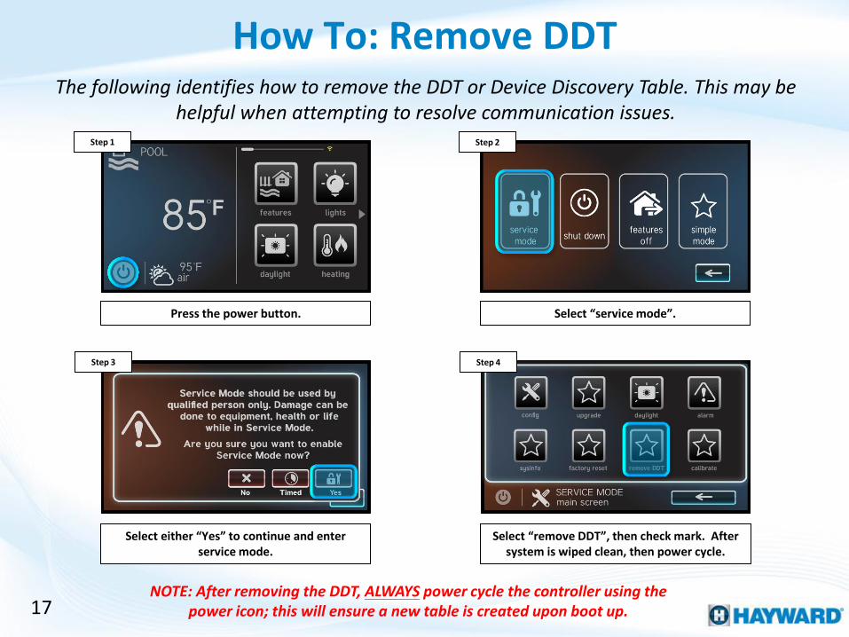
How To: Remove DDT
17
Press the power button. Select “service mode”.
Step 2 Step 1
Select “remove DDT”, then check mark. After system is wiped clean, then power cycle.
Select either “Yes” to continue and enter service mode.
Step 4 Step 3
NOTE: After removing the DDT, ALWAYS power cycle the controller using the power icon; this will ensure a new table is created upon boot up.
The following identifies how to remove the DDT or Device Discovery Table. This may be helpful when attempting to resolve communication issues.

How To: Reset to Factory Default
18
Press the power button. Select “service mode”.
Step 2 Step 1
Select “factory reset”, then check mark. After system is wiped clean, it will power cycle.
Select either “Yes” to continue and enter service mode.
Step 4 Step 3
NOTE: Doing a factory reset will remove all configurations, schedules, and times. Following a factory reset, the system will have to be reprogrammed.
The following identifies how to reset the system to factory default, this can be helpful in resolving obscure schedule or command issues.

Troubleshooting
VS Omni®

20
MSP: Blank Display
Screen still blank? YES
NO
Verify display power off hub PCB (12vDC)
NO
Is voltage correct?
Problem solved
YES
Verify display power on display
back (12vDC)
1. Controller: Blank Display
Tap screen to wake up
Test hub input power
(120/240vAC)
NO
YES
NO
Replace Hub PCB:
HLXHIOPCB
Resolve at breaker / timeclock
Replace cable: HLX485100
Is voltage correct?
YES
Replace Controller
HLHCONTROL
Is voltage correct?

21
The Controller display runs off of 12vDC. This power is supplied by the VS Omni wiring hub. Inspect the wire from the controller to the hub for damage.
Tap on the controller screen in an attempt to wake the display from a system shutdown. Make sure glare is not
the culprit. IF tapping does not change the display state, go to step 1B.
The controller display is powered by wiring hub. On the top right of the wiring hub PCB, test for 10.2-
13.8vDC between pins 2 & 4 (top to bottom). IF voltage is correct, jump to slide 1E. IF no/low voltage, go to 1C.
Tap On the Screen Step 1A Step 1B
Test for 12VDC
1. Controller: Blank Display

22
The wiring hub can be powered either by 120 or 240vAC. Ensure the breaker / timeclock is not tripped or OFF.
Unplug input power connector. Verify 120 or 240vAC. IF 120/240vAC is present, replace the hub PCB
(HLXHIOPCB). IF not, go to step 1D.
Test power hub power at the breaker/timeclock for 120 or 240vAC. IF correct, fix wiring/connections. IF not,
resolve at breaker/timeclock.
Test Wiring Hub Input Step 1C Step 1D
Test Breaker/Timeclock
1. Controller: Blank Display (cont.)

23
The controller enclosure is deigned to be water resistant, with a gasket seal. Care should be taken during reassembly.
On the back of the controller, remove the 4 screws that secure the controller display to the housing. This
provides access to the controller PCB. Once complete, go to step 1F.
Test cable that plugs into controller PCB for 12vDC between terminals 1 & 3 (left to right). IF power is
present, replace controller (HLHCONTROL). IF no/low voltage replace controller cable (HLX485100).
Access Controller PCB Step 1E Step 1F
Test Controller PCB Input
1. Controller: Blank Display (cont.)

24
NO
Jump to Section 3
Confirm programming & port
location, is valve handle engaged?
YES
YES
Alarms: Comm Loss Wiring Hub?
Problem solved
Valve Not Rotating
2. Valve Not Rotating
Pull handle to engage
valve
NO
Toggle actuator switch, does valve move?
YES
NO
Is hub supplying 24vAC?
YES In service, will valve rotate?
NO
Replace failing actuator(s):
GVA-24
YES Problem solved
does valve move?
YES
NO
YES
Replace Hub PCB:
HLXHIOPCB
Reprogram, does valve
rotate?
NO
Replace Hub PCB:
HLXHIOPCB
NO
Reprogram, if problem persists Contact Support (908) 355.7995

25
Comm Loss Alarms can prevent equipment, such as a valve actuator, from functioning. The alarms icon is located on the right side of the controller dashboard. Before
proceeding, verify whether a Comm Loss Alarm appears.
On the display, select the “alarm” icon (on right side of the screen). IF an Comm Loss – Wiring Hub appears go to section 3, IF it does not appear, go to 2B.
Step 2A
2. Valve Not Rotating
Check Display for a Comm Loss - Wiring Hub Alarm

26
The valve actuator circuit will only receive power from the wiring hub if it is correctly programmed. Verify the valve is not only programmed but is also plugged into the
corresponding valve actuator port.
Make sure valve actuator is programmed to the correct port. To confirm, also test the actuator on the other
port. IF programming is confirmed, go to step 2C. IF not, program the valve using quick edit.
Step 2B Step 2C
Confirm Programming
Verify the actuator shaft is engaged (as shown above). IF the valve moves freely, when rotating the handle, pull up on the handle to engage, IF engaged, proceed
to step 2D.
Verify Shaft is Engaged
2. Valve Not Rotating (cont.)
PRO TIP: To add/remove & re-add a valve, go to config>config wizard>quick edit>feature (to add/remove & re-add)>add feature>select valve port>save.

27
NOTE: GVA-24s come factory preset with toggle switches in the OFF position. For the valve actuator to rotate based on supplied power, the switch will have to be moved to
the ON1 or ON2 position (which will depend on the installation).
Locate toggle switch (bottom of actuator). Verify switch is either in ON1 or ON2 positions. Toggle the switch
between ON1/ON2, IF actuator does not move, go to step 2E, otherwise skip to step 2G.
On the wiring hub PCB, verify 20-24vAC between pin 1-3 or 2-3 (depending on expected valve position). IF no/low voltage is present, go to step 2F. IF correct,
replace actuator (GVA-24).
Check Actuator Toggle Step 2D Step 2E
Check ACT power
2. Valve Not Rotating (cont.)

28
NOTE: If the valve rotates when activated through service mode, but will not do so while in normal operation. Than either the programming or an interlock are most
likely causing the problem.
Reprogram the value using quick edit. IF the valve still does not rotate when turned ON through the controller, replace the Hub PCB (HLXHIOPCB).
Put the controller in service mode and attempt to force the valve on. IF the still does not rotate, replace the
Hub PCB (HLXHIOPCB). IF the valve rotates, go to 2H.
Reprogram Valve Step 2F Step 2G
Service Mode
2. Valve Not Rotating (cont.)

29
If the valve rotates when activated through service mode, but will not do so while in normal operation. Than either the programming or an interlock are most likely
causing the problem.
2. Valves Not Rotating (cont.)
Using quick edit, reprogram the valve. IF the valve still will not rotate while being activating through the controller, then please contact support (908) 355-7995 for additional support.
Step 2H
Reprogram Valve
PRO TIP: To add/remove & re-add a valve, go to config>config wizard>quick edit>feature (to add/remove & re-add)>add feature>select valve port>save.
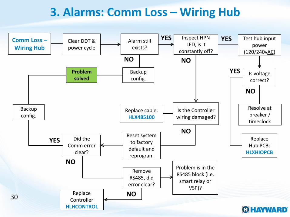
Comm Loss – Wiring Hub
NO NO
YES YES
3. Alarms: Comm Loss – Wiring Hub
Clear DDT & power cycle
30
Alarm still exists?
Backup config.
Problem solved
Inspect HPN LED, is it
constantly off?
Is the Controller wiring damaged?
Reset system to factory
default and reprogram
YES
Replace cable (??)
Test hub input power
(120/240vAC)
YES
NO
Replace Hub PCB:
HLXHIOPCB
Resolve at breaker / timeclock
Is voltage correct?
NO Did the
Comm error clear?
NO
Replace Controller
HLHCONTROL
Remove RS485, did
error clear?
NO
Problem is in the RS485 block (i.e.
smart relay or VSP)?
Backup config.
Replace cable: HLX485100
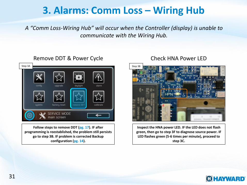
31
A “Comm Loss-Wiring Hub” will occur when the Controller (display) is unable to communicate with the Wiring Hub.
Follow steps to remove DDT (pg. 17). IF after programming is reestablished, the problem still persists
go to step 3B. IF problem is corrected Backup configuration (pg. 14).
Inspect the HNA power LED. IF the LED does not flash green, then go to step 3F to diagnose source power. IF LED flashes green (5-6 times per minute), proceed to
step 3C.
Remove DDT & Power Cycle Step 3A Step 3B
Check HNA Power LED
3. Alarms: Comm Loss – Wiring Hub
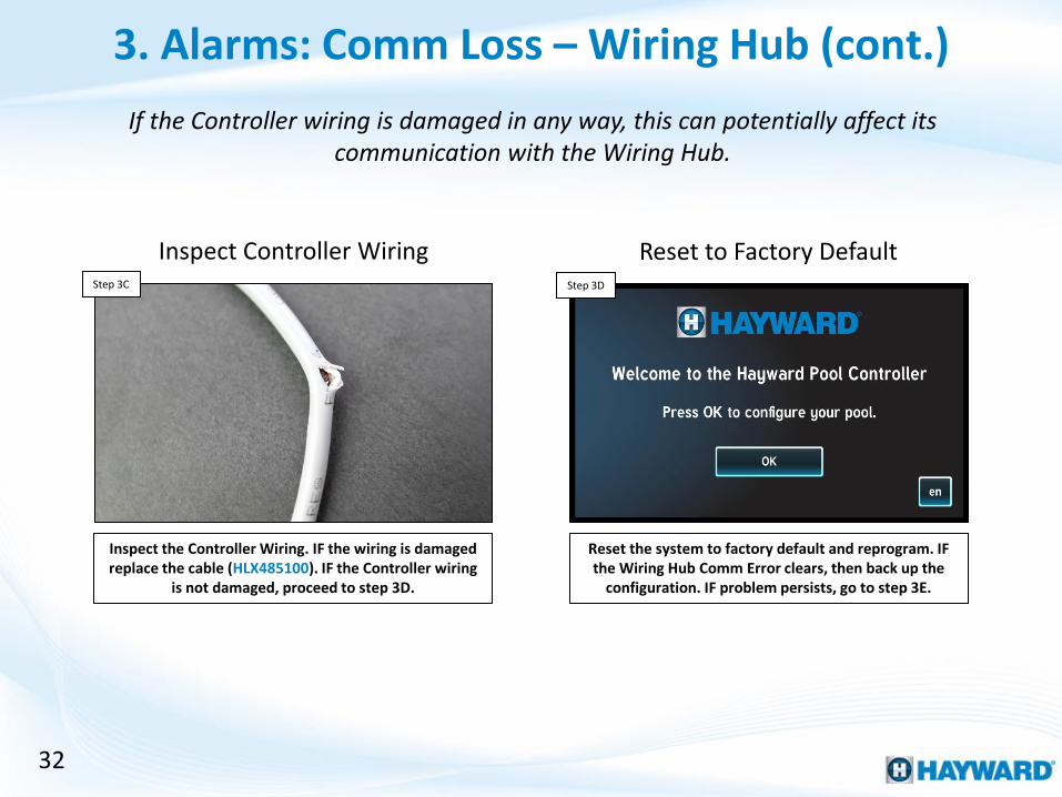
32
If the Controller wiring is damaged in any way, this can potentially affect its communication with the Wiring Hub.
Inspect the Controller Wiring. IF the wiring is damaged replace the cable (HLX485100). IF the Controller wiring
is not damaged, proceed to step 3D.
Reset the system to factory default and reprogram. IF the Wiring Hub Comm Error clears, then back up the
configuration. IF problem persists, go to step 3E.
Inspect Controller Wiring Step 3C Step 3D
Reset to Factory Default
3. Alarms: Comm Loss – Wiring Hub (cont.)
33
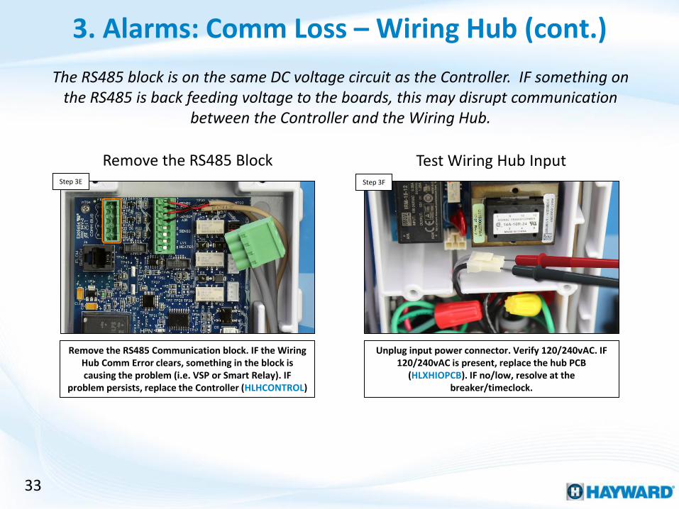
The RS485 block is on the same DC voltage circuit as the Controller. IF something on the RS485 is back feeding voltage to the boards, this may disrupt communication
between the Controller and the Wiring Hub.
Remove the RS485 Communication block. IF the Wiring Hub Comm Error clears, something in the block is causing the problem (i.e. VSP or Smart Relay). IF
problem persists, replace the Controller (HLHCONTROL)
Unplug input power connector. Verify 120/240vAC. IF 120/240vAC is present, replace the hub PCB
(HLXHIOPCB). IF no/low, resolve at the breaker/timeclock.
Remove the RS485 Block Step 3E Step 3F
Test Wiring Hub Input
3. Alarms: Comm Loss – Wiring Hub (cont.)

34
Comm Loss – Smart Relay
Inspect cable & connection
Are wires free of
damage?
Section B
YES
NO
YES Are any LEDs lit on the Smart
Relay?
YES
NO
NO
Does the Smart Relay have line
power?
4. Alarms: Comm Loss – Smart Relay
Replace cable HLX485100, did the error clear?
YES Problem solved
NO
Go to Section B
YES Replace Smart Relay:
HLX485RELAY
NO Resolve at
breaker
Clear DDT & power cycle
Does the error still persist?
Problem solved
Isolate RS485 & verify Smart Relay wiring
Did the error clear?
YES Problem is related to
RS485 wiring or equipment NO
Reset system to factory default &
reprogram
YES
NO Replace
Smart Relay: HLX485RELAY
Backup config.
Did the Error Clear?

35
The Remote LED determines whether the Smart Relay is communicating. The Relay LED determines whether the Relay is actively ON or OFF.
Inspect the Smart Relay cable for damage. IF no breaks exist and/or connections are correct, go to step 4B. IF
comm cable is damaged , replace cable and retest (HLX485100).
Inspect the two LED indicators on the front of the Smart Relay. There is a Remote LED and a Relay status LED. IF no LEDs appear, go to Step 4C. IF any LEDs are
lit/flashing, jump to Step 4D.
Check Cable/Connection Step 4A Step 4B
Verify Smart Relay LED Status
4. Alarms: Comm Loss – Smart Relay

36
The Smart Relay can be wired for either 120vAC or 240vAC line voltage (depending on the equipment wired in). For 120vAC = Grey & Black input; for 240vAC = Black &
Red/Grey.
Verify line power to the Smart Relay between the grey & black (120vAC) or black & red/grey (240vAC). IF
no/low voltage, correct at power source. IF correct, replace the Smart Relay (HLX485RELAY).
Follow steps to remove DDT (pg. 17). IF after programming is reestablished, the problem still persists
go to step 4E. IF problem is corrected Backup configuration (pg. 14).
Smart Relay Input Step 4C Step 4D
Remove DDT & Power Cycle
4. Alarms: Comm Loss – Smart Relay (cont.)

Isolate RS485 Wiring
37
Reset the system to factory default and reprogram. IF the Smart Relay Comm Loss clears, then back up the configuration. IF problem persists, replace the Smart
Relay (HLX485RELAY).
Step 4E Step 4F
Isolate the RS485 wiring and verify Smart Relay is wired correctly. IF removing all other equipment clears comm error, then problem is in the RS485 wiring. IF problem
persists, go to Step 4F.
4. Alarms: Comm Loss – Smart Relay (cont.)
IF something on the RS485 is back feeding voltage to the boards, this may disrupt communication between the Wiring Hub & Smart Relay.
Reset to Factory Default

38
Comm Error - VSP
NO
YES Is comm wiring damaged?
YES Replace comm cable, & retest
NO
Verify Comm wiring on both pump and Hub
Correct (pg. 8-9), is the error clear?
NO
Comm wiring correct?
Verify pump HUA is in
system info
YES
5. Alarms: Comm Error - VSP
Is the HUA present?
NO Verify pump input power
(187-253vAC)
Is voltage correct?
Resolve at pump
breaker
NO
YES Problem solved
Reprogram, if problem persists Contact Support (908) 355.7995
Please Contact Support (908) 355.7995
The problem may be related to the pump display
(TriStar 950) or the pump drive (TriStar 900, MaxFlo
VS or Super Pump VS
YES

TriStar VS 950
All other VS Pumps
VS Omni
7 A 2
8 B 3
- COM 4
39
It is important to following the communication wiring diagrams as they may differ from pump to pump.
Verify the communication cable from the Hub (RS485) to the Pump is correctly wired (pg. 8-9). IF correct,
proceed to Step 5B. IF incorrect, shut down power to both the Hub and Pump and rewire.
Inspect the pump’s comm cable for damage. IF no breaks exist and/or connections are correct, go to step 5C. IF comm cable is damaged, replace cable and retest
(TBD).
Verify Comm Connections Step 5A Step 5B
Check Comm Cable
5. Alarms: Comm Error - VSP

40
If the HUA appears under System Info, that means the VS Omni can currently see that the pump is attached. If the HUA appears and a communication error exists, there
may be a problem with the configuration.
Navigate to Config>System Info and verify the Pump HUA is showing up in the list. IF HUA does not appear,
go to 5D. IF it does, reprogram VS Omni, contact support if the problem still persists: (908) 355-7995.
If pump is not powered, it will not be able to communicate with VS Omni. Verify pump has 187-
253vAC. IF no/low voltage, resolve at pump breaker. IF correct please contact support (908) 355-7995*.
Verify HUA Under System Info Step 5C Step 5D
Verify Pump Power
5. Alarms: Comm Error – VSP (cont.)
IF the pump is powered and the HUA is not showing up in the VS Omni the problem may be related to pump compatibility, the pump display (TriStar
950), or the pump drive (TriStar 900, Maxflo VS, Super Pump VS).

WiFi: No Connectivity
6. Wi-Fi: Lost Link/MSP ID Not Found
Power cycle router & confirm password & retry
Wi-Fi setup
While diagnostics is running, were any red flags identified?
YES Is firmware up-to-date?
YES
NO Upgrade
firmware & retest
41
NO
Does the problem persist?
NO
YES Does the problem persist?
Problem solved
Problem solved
NO
Please Contact Support (908) 355.7995
This could be a packet loss problem (related to
router/network incompatibility or long
distances
YES
Test Description
X Verifying Netlink Network password was not accepted
X Verifying Network Address Controller did not receive IP credentials (supplied by router)
X Verifying Network Connection Router did not Communicate
X Verifying DNS Web ping failed (check with internet connection)
X Verifying Internet Connection Failed to reach OmniLogic Web Server
For more help, please Contact
Support (908) 355.7995

42
NOTE: These steps are only applicable when communicating via Wi-Fi. For best results, first make sure firmware is updated to the latest rev.
Network passwords ARE case sensitive.
Under config>system info confirm all equipment is up-to-date by comparing the system versions with those
available on Hayward’s Support>Automation>VS Omni>Firmware Upgrades. Follow steps on pg. 11-13 to
download an upgrade firmware. Once firmware is upgraded, proceed to Step 6B.
Power cycle the network router and confirm the 2.4Ghz Wi-Fi signal and password. Retry network setup under: config>network. After running network diagnostics: IF no red flags were generated AND the problem persists,
please contact support (908) 355-7995*. IF red flags appeared, proceed to Step 6C.
Verify Firmware is Up-To-Date Step 6A Step 6B
Power Cycle Network & Retry
6. Wi-Fi: Lost Link/MSP ID Not Found
*If no red flags appeared after the network diagnostics were run, the problem may be related to packet loss caused by router/network incompatibility or
long distances.

Test Description
X Verifying Netlink Network password was not accepted (check case / password accuracy)
X Verifying Network Address Controller did not receive IP credentials from the router (Verify router powered and active)
X Verifying Network Connection Router did not Communicate (check router activity LEDs and confirm router is communicating to other wireless devices.
X Verifying DNS Web ping failed (check internet connection and web browsing capabilities, this could be an Internet Service Provider problem)
X Verifying Internet Connection Failed to reach OmniLogic Web Server (contact support 908-355-7995)
43
6. Wi-Fi: Lost Link/MSP ID Not Found (cont.)
The Network Diagnostics will run immediately after entering the network password. If any of the five tests returns with an error, attempt to correct using the information
supplied and retest.
The table provided above outlines why each test may have failed. IF the problem can not be resolved, please contact support (908) 355-7995.
Step 6C
Network Diagnostics: Red Flags

44
CL Lights: Out-of-
Sync/OFF
7. CL lights (14v): Out-of-Sync/OFF
Are the CL Lights ON?
NO
YES
YES
In service mode, toggle lights ON/OFF
Did CL lights illuminate?
YES
In service mode, with
lights relay ON
Test transformer output for 14vAC,
is it present?
Replace defective lights
YES
Test transformer input for 120vAC, is
it present?
NO
NO
Install a snubber:
(GLX-HAL-XSNUB), then resync lights
Replace, 14V transformer
Test Smart Relay input for 120vAC, is
it present?
Resolve at breaker
NO
Replace Smart Relay:
HLX485RELAY
YES
NO
Install a snubber: (GLX-HAL-XSNUB), then resync lights
Problem solved
Problem solved

45
Note: The Lights can fall out of sync in three different ways: 1. The Lights OFF, but the controller reports they are ON, 2. The Lights are ON in a different color or show than
what the controller is reporting, 3. The Lights are out-of-sync with each other.
Activate the lights through the controller (if they aren’t already in this state) and determine whether the
physical lights are illuminated. IF the lights are on go to Step 7B. IF not on, go to 7C.
If the lights are on, but out-of-sync, then simply resyncing the lights should correct the issue. However, Installing a snubber (GLX-HAL-XSNUB) will likely reduce
reoccurrences.
Activate Lights & Observe Step 7A Step 7B
Install a Snubber & Resync
7. CL lights (14v): Out-of-Sync
*A snubber should be installed in the 14V transformer and is rated for low voltage light offerings ONLY (UCL, CL320/160, CL80/40).

46
Low voltage lighting should be powered off the 14 volt circuit of the transformer, if multiple taps are included in the transformer, verify they are connect to the 14v tap.
Put system in service mode (power>service mode), then toggle lights on, off, & back on. IF lights are
illuminating, install a snubber & resync lights after exiting service. IF they did not illuminate, go to 7D.
Open lighting transformer and test for 14vAC on the output side. IF voltage is correct on the output side of
the transformer, replace defective lights. IF no/low voltage, go to step 7E.
Service Mode & Toggle Lights Step 7C Step 7D
Test Transformer Output
7. CL lights (14v): Out-of-Sync
14VAC

47
To determine the source of the disconnect, test the input and output sides of the transformer while calling for lights to be ON.
Test the input side of the lighting transformer for 102-138vAc. IF no/low voltage, go to step 7F. IF voltage is
correct, replace the transformer.
Test the Smart Relay’s input power for 102-138vAC. IF power is correct replace the Smart Relay
(HLX485RELAY). IF no/low voltage, resolve at breaker.
Test Transformer Input Step 7E Step 7F
Test Smart Relay Input
7. CL lights (14v): Out-of-Sync
120VAC

Additional Information
VS Omni®

49
How and When to Install a Snubber
14V Output
120V Input
300W
Snubber
GLX-HAL-XSNUB
• IF an isolation transformer for low voltage lighting is installed.
• IF turning the light OFF or toggling ON/OFF (either via light switch or relay) causes a GFCI breaker to trip, even on unrelated circuits.
• IF lights are frequently falling out of sync.
• THEN connect the GLX-HAL-XSNUB, a snubber capacitor across the primary leads (line to neutral) in the transformer.
If the following conditions exist then a snubber may be recommended:

50
Reading Serial Numbers
3K11284- 123456
3K11284 = Standard Warranty Term
3K11284 = Product Family
3K11284 = Year of Manufacture
3K11284 = Day of Manufacture
123456 = Manufacturing ID