vrm video recording manager - bosch...
TRANSCRIPT
VRM Video Recording ManagerVersion 2.20
en Operator's Manual

VRM Video Recording Manager Table of Contents | en 3
Bosch Sicherheitssysteme GmbH Operator's Manual DOC | V.2.20 | 2011.06
Table of Contents
1 Introduction 5
2 System overview 62.1 VRM Functions 62.2 VRM Server 62.3 Configuration Manager 62.4 VRM Monitor 6
3 Installation 73.1 Installing 73.2 Verifying installation 73.3 Uninstalling 8
4 Licensing 94.1 Licensing the software 9
5 Used icons 10
6 Getting started 116.1 Starting VRM Monitor 116.2 Starting Configuration Manager 116.3 Enabling the Cameras tab 11
7 Configuring a VRM system 127.1 Adding a VRM to the system 127.2 Managing iSCSI Systems 127.2.1 Adding an iSCSI system 127.2.2 Removing an iSCSI System 127.2.3 Adding LUNs 127.2.4 Formatting LUNs 137.2.5 Configuring the LUN type 137.3 Allocating detected devices 137.4 Authorizing an encoder permanently 147.5 Clearing device allocations 147.6 Creating groups of allocated devices 147.7 Allocating a device manually 147.8 Managing recording 157.8.1 Configuring local storage (firmware version 4.0 or later) 157.8.2 Configuring alarm tracks (firmware up to 3.5x) 157.9 Configuring manual recording mode 167.10 Configuring automatic recording mode 167.11 Configuring logs 16
4 en | Table of Contents VRM Video Recording Manager
DOC | V.2.20 | 2011.06 Operator's Manual Bosch Sicherheitssysteme GmbH
8 Configuring a failover server 17
9 Managing user groups and permissions 189.1 Configuring users and user groups 189.2 Configuring camera permissions 19
10 Configuring Automatic Network Replenishment 20
11 User interface 2111.1 Device Allocator dialog box 2111.2 Failover VRM Server information 2111.3 VRM Settings tab 2111.4 User Management tab 2311.4.1 User dialog box 2311.4.2 Group dialog box 2311.5 iSCSI System Access tab 2411.6 Default Configuration tab 2411.7 Load Balancing tab 2511.8 Target Settings tab 2511.8.1 LUN Assignment dialog box 2611.9 Recording Management tab (only firmware version 4.0 or later) 2611.10 Storage Medium tab (only firmware version up to 3.5) 2711.11 Recording Preferences tab 2811.12 Retention time tab 2911.13 Privileges tab 2911.14 Advanced tab 2911.15 License tab 30
Index 31
VRM Video Recording Manager Introduction | en 5
Bosch Sicherheitssysteme GmbH Operator's Manual DOC | V.2.20 | 2011.06
1 IntroductionThis manual is intended for persons responsible for setting up, configuring and using the VRM Video Recording Manager application.
6 en | System overview VRM Video Recording Manager
DOC | V.2.20 | 2011.06 Operator's Manual Bosch Sicherheitssysteme GmbH
2 System overviewYou use VRM Video Recording Manager to organize video recordings in a CCTV system. This involves recording video sequences that are provided in the system by an IP camera or an encoder (for example a Dinion IP camera or VIP X1600) on iSCSI RAID arrays. The recordings can be replayed, exported and burnt to CD or DVD using Bosch Video Client.
2.1 VRM FunctionsThe application comprises the following modules:– VRM Server– VRM Monitor– Configuration Manager
2.2 VRM ServerVRM Server manages configuration details and system settings, and it also acts as a centralized service for the communication of individual modules.
2.3 Configuration ManagerUse Configuration Manager to configure the VRM system. The program can be installed on one or more Windows PCs that provide network access to the computer on which VRM Server has been started.Using this program, you specify which IP cameras and encoders have their recordings managed using the VRM system, as well as the iSCSI storage systems on which the recordings are stored.Configuration Manager allows you to create users who may belong to various user groups with different rights. Only users who are set up here can access the system settings and the recordings managed in the VRM system.Access to the VRM system is only permitted for users who log on using a valid user ID. Different types of access privilege may be granted.Recordings managed by the VRM system can be played back, exported and, if necessary, burnt to CD or DVD using Bosch Video Management System or Bosch Video Client.
2.4 VRM MonitorThe VRM Monitor module is provided to monitor the VRM system. The module is automatically installed together with VRM Server. This is where information about the connected BVIP devices (Bosch Video over IP) and storage systems, as well as about the recordings, is displayed.VRM Monitor provides limited options for replaying the recordings. You cannot configure VRM with VRM Monitor.
NOTICE! You need Microsoft Internet Explorer 6.0 or later for the correct display.Check the Windows Firewall settings. Default settings can possibly prohibit the display of live images.
CAUTION! For playback from within VRM Monitor you must have installed Video SDK V. 4.4x. Playback does not work correctly with Video SDK V. 5.x.
VRM Video Recording Manager Installation | en 7
Bosch Sicherheitssysteme GmbH Operator's Manual DOC | V.2.20 | 2011.06
3 InstallationFor system requirements and recommended Bosch server hardware see the data sheet for Video Recording Manager in the Online Product Catalog on http://www.boschsecurity.com > Video > Management Systems > VRM - Video Recording Manager. (The navigation path is subject to change).
VRM ServerThe VRM Server service is installed on a Windows platform. Ensure that a possibly installed web server does not interfere with VRM's HTTP and HTTPS ports.Do not install any of the following applications from VIDOS Pro Suite on the computer where you install VRM:– VIDOS Server– VIDOS-NVR– VIDOS Monitor WallIt is advisable to install VRM Server on a dedicated platform.Note: For installing VRM Server you need Windows administrator rights.
VRM MonitorVRM Monitor is an HTML-based interface for monitoring the VRM system. The module is automatically installed together with VRM Server.
Configuration ManagerConfiguration Manager is installed along with VRM Server. The program can also be installed on other PCs with network access to the computer on which VRM Server has been started and to the devices that are to be managed.
3.1 Installing1. Close all other applications before beginning the installation.2. Download the software package from the Online Product Catalog and extract the zip file
locally.3. Select the extraction directory and double-click index.htm.4. Select the required language for the user interface.5. Under Installation, click VRM Video Recording Manager.
The setup wizard opens and guides you through the installation.
When selecting components, a description for each one is displayed when you hover the mouse cursor over them.
3.2 Verifying installationThe Video Recording Manager service is started automatically after installation and every time the computer is started up.Follow the steps below to check that VRM Server has been installed correctly:1. Click Start > Control Panel.2. Select Administrative Tools.3. Select Component Services.4. Select Services (Local).5. Search for the Bosch Video Recording Manager entry in the list of all installed services.
The following details must appear here:
– Status: Started– Startup Type: Automatic
8 en | Installation VRM Video Recording Manager
DOC | V.2.20 | 2011.06 Operator's Manual Bosch Sicherheitssysteme GmbH
3.3 UninstallingIf you no longer wish to use one of the programs on a computer, you can uninstall the program at any time.
CAUTION! The license for any program requiring one applies to the computer hardware and cannot be used on another computer. Please contact your sales partner if you want to use a license on another computer.
NOTICE! When you uninstall a licensed program and then install an update on the same PC, your license is unaffected.
VRM Video Recording Manager Licensing | en 9
Bosch Sicherheitssysteme GmbH Operator's Manual DOC | V.2.20 | 2011.06
4 LicensingWhen you purchase VRM Video Recording Manager, you are provided with an authorization number. This number can be found in an envelope that is included with the scope of delivery or you receive it via e-mail.Using this number and the installation code that you can access via the Configuration Manager program, go to the Bosch Software Licensing Manager Internet platform and generate the activation keys.These keys are then entered using Configuration Manager. Once this process is complete, you can use VRM Video Recording Manager permanently in line with terms of the acquired license.You can test VRM for 30 days after installation.
4.1 Licensing the software
Main window > Devices tab > > Service > License tab1. Make a note of the Installation code entry — the copy-and-paste function is supported.2. On a computer with Internet access, enter the following URL into your browser:
https://activation.boschsecurity.com
If you do not have an account to access the Bosch License Activation Center, either create a new account (recommended) or click the link to activate a new license without logging on. If you create an account and log on before activating, the License Manager keeps track of your activations. You can then review this at any time.
Follow the instructions to obtain the License Activation Keys.
3. Return to Configuration Manager > License tab.4. Under Activation key, enter the first activation key (Activation Key 1) — the copy-and-
paste function is supported.
5. Click to save the first activation key. 6. Under Activation key, enter the second activation key (Activation Key 2).
7. Click to save the second activation key. 8. Restart the VRM Server service for which you have entered the license.
Video Recording Manager is now available as a full version.
Relevant information about the license is displayed on the License tab in Configuration Manager.
CAUTION! The license applies to the computer on which VRM Server is installed. If you have uninstalled VRM Server and wish to reinstall it on a different computer, you must request new activation keys.
10 en | Used icons VRM Video Recording Manager
DOC | V.2.20 | 2011.06 Operator's Manual Bosch Sicherheitssysteme GmbH
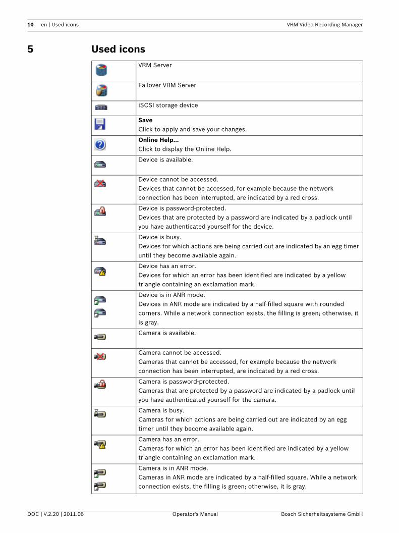
5 Used iconsVRM Server
Failover VRM Server
iSCSI storage device
SaveClick to apply and save your changes.
Online Help...Click to display the Online Help.
Device is available.
Device cannot be accessed.Devices that cannot be accessed, for example because the network connection has been interrupted, are indicated by a red cross.
Device is password-protected.Devices that are protected by a password are indicated by a padlock until you have authenticated yourself for the device.
Device is busy.Devices for which actions are being carried out are indicated by an egg timer until they become available again.
Device has an error.Devices for which an error has been identified are indicated by a yellow triangle containing an exclamation mark.
Device is in ANR mode.Devices in ANR mode are indicated by a half-filled square with rounded corners. While a network connection exists, the filling is green; otherwise, it is gray.
Camera is available.
Camera cannot be accessed.Cameras that cannot be accessed, for example because the network connection has been interrupted, are indicated by a red cross.
Camera is password-protected.Cameras that are protected by a password are indicated by a padlock until you have authenticated yourself for the camera.
Camera is busy.Cameras for which actions are being carried out are indicated by an egg timer until they become available again.
Camera has an error.Cameras for which an error has been identified are indicated by a yellow triangle containing an exclamation mark.
Camera is in ANR mode.Cameras in ANR mode are indicated by a half-filled square. While a network connection exists, the filling is green; otherwise, it is gray.
VRM Video Recording Manager Getting started | en 11
Bosch Sicherheitssysteme GmbH Operator's Manual DOC | V.2.20 | 2011.06
6 Getting startedThe Configuration Manager program is used to set and adjust the VRM system. The program can be installed on any PC with network access to the computer on which VRM Server has been started and to the devices that are to be managed.
6.1 Starting VRM Monitor1. Start Internet Explorer on a PC that has network access to the VRM Server computer.2. In the address bar, enter the IP address of the VRM Server computer and press <ENTER>.
If you are starting VRM Monitor on the VRM Server computer, enter the IP address for the localhost followed by the port number if the port number is not 80:http://127.0.0.1:<port number>/
3. Access to VRM Monitor is only possible for authorized persons. For this reason you will now be prompted to log on using your user ID. If you do not have the appropriate rights, you cannot view any recordings.
The functions described in the following sections are now available.On the left-hand side, you will see the navigation bar. Click the appropriate entry. The information is displayed on the right-hand side.
6.2 Starting Configuration ManagerTo start the program: Click Start, point to Programs, point to Bosch Configuration Manager, and then click
Configuration Manager.
6.3 Enabling the Cameras tabMain window > System tabEnable the Cameras tab, when it is not displayed.1. Expand the Applications folder.2. Click Configuration Manager.3. Click the Appearance tab.4. Click to check the Show ’Cameras’ tab check box.5. Restart Configuration Manager.
CAUTION! Treat your logon details as confidential.Ensure that the password is not saved in the browser.
CAUTION! If a computer on which VRM Server is started is simultaneously accessed by multiple Configuration Manager programs, this can result in an inconsistent VRM configuration. Ensure that different people do not make changes to the configuration at the same time.
12 en | Configuring a VRM system VRM Video Recording Manager
DOC | V.2.20 | 2011.06 Operator's Manual Bosch Sicherheitssysteme GmbH
7 Configuring a VRM systemTo configure a VRM system perform the following tasks:– Section 7.1 Adding a VRM to the system, page 12– Section 7.2 Managing iSCSI Systems, page 12– Section 7.3 Allocating detected devices, page 13– Section 7.5 Clearing device allocations, page 14– Section 7.6 Creating groups of allocated devices, page 14– Section 7.7 Allocating a device manually, page 14– Section 7.8 Managing recording, page 15– Section 7.9 Configuring manual recording mode, page 16– Section 7.10 Configuring automatic recording mode, page 16– Section 7.11 Configuring logs, page 16
7.1 Adding a VRM to the systemMain window > Network tabYou add a VRM to the system to enable assigning storage devices and encoders to this VRM.1. Right-click the desired VRM and click Add to System....
The Add Device to System dialog box is displayed.
2. In the Group list, select Configuration Manager.The VRM is added to the system and is displayed on the Devices page.
Required configuration changes are performed automatically.
7.2 Managing iSCSI SystemsTo configure a working iSCSI storage, you must add an iSCSI system and add LUNs.
7.2.1 Adding an iSCSI system
Main window > Devices tab > Right-click > Add iSCSI System... command > Add iSCSI System dialog box1. Enter the IP address of the iSCSI storage system.2. Select the type.
Configure the available device types (for example Bosch and certain Infortrend and NetApp storage systems). Configure other types directly via the management software of the relevant storage system.
3. Enter the iSCSI storage system configuration password and confirm it.The VRM system attempts to establish a connection with the device.
The device is added to the system and displayed in the tree structure.
7.2.2 Removing an iSCSI System
Main window > Expand > Right-click desired > Delete command
7.2.3 Adding LUNs
Main window > Devices tab > Expand > Expand Storage Systems > Add individual LUNs to the system and configure them. You can add a backup LUN that has been used in another VRM system. If the backup LUN was formatted with VRM 2.10 or later, it is automatically detected as a backup LUN.
VRM Video Recording Manager Configuring a VRM system | en 13
Bosch Sicherheitssysteme GmbH Operator's Manual DOC | V.2.20 | 2011.06
The type of a LUN types (standard/read-only/backup) is stored on the LUN itself, so if configuration is lost, the LUN can be added without risk of data loss. The correct type of the LUN is read out and is set correctly.
1. Right-click an iSCSI system and click LUN Assignment... to add new LUNs. The LUN Assignment dialog box appears.The left pane displays the LUNs that are available for this target and have not yet been added to the system. The right pane displays the LUNs that have already been added to the system.
2. Drag a LUN from the left to the right pane to add it.3. Activate the Restore database option if you want to retain data when the LUN is added.4. Click OK.
The LUNs are added to the VRM system. The LUN Assignment dialog box is closed.
Removing LunsTo remove LUNs from the system, open the LUN Assignment dialog box and drag the LUNs in question from the right to the left pane.For the LUNs added to the system, make further settings if necessary.
7.2.4 Formatting LUNs
Main window > Devices tab > Expand > Expand Storage Systems > Expand >
> Target SettingsYou can format each added LUN. Formatting deletes all data on this LUN.1. In the Format column, select the corresponding check box for each LUN that you want to
format.2. Click Set to start formatting.
7.2.5 Configuring the LUN type
Main window > Devices tab > Expand > Expand Storage Systems > Expand >
> Target SettingsYou can configure the type of each added LUN. Some types require formatting of the LUN.1. In the Type list, select the corresponding item for each LUN that you want to configure.2. Click Set to start configuration.
7.3 Allocating detected devicesMain window > Tools menu > Device Allocator... command > Device Allocator dialog boxOn devices allocated during recording the configuration changes are not performed as long as recording is active. Perform the configuration changes after recording has stopped.Note: When adding an encoder to the VRM, recording of this device stops automatically.1. Drag devices from the left pane on the VRM item on the right pane.
The encoder is now a child item of the VRM item.
2. Click OK.The encoders are allocated to the VRM system and are recorded.
Required configuration changes are performed automatically.
14 en | Configuring a VRM system VRM Video Recording Manager
DOC | V.2.20 | 2011.06 Operator's Manual Bosch Sicherheitssysteme GmbH
7.4 Authorizing an encoder permanently
Main window > Devices tab > Expand > Expand Devices > > General > Unit Access tabEnter the access data for an encoder so that you do not have to repeat authorizing after each restart of Configuration Manager. For VRM it is mandatory to select the user called service and the corresponding password.To authenticate permanently:1. In the Device access pane, enter the user name and password.
2. Click .
7.5 Clearing device allocationsMain window > Tools menu > Device Allocator... command > Device Allocator dialog boxYou can remove devices from the VRM system at any time by clearing the allocation. The devices will then no longer be listed in the tree structure.
1. Drag a device from the right to the left pane.2. Click OK.
The storage media type is automatically set to Off — no more recordings are made for this device until it is manually reconfigured for this.
Groups can also be deleted in the same way. If you delete a group, you also clear the allocation of all devices that you have allocated to that group.
7.6 Creating groups of allocated devicesMain window > Tools menu > Device Allocator... command > Device Allocator dialog boxThe context menu in the Device Allocator dialog box enables you to group the devices in the list.1. In the Allocated devices area, right-click New Group....2. Enter a name for the new group.3. Click OK.
The group is displayed in the list.
You can rename the group later by using the context menu.
4. Drag a device from the list to the group name.The device is added to the group.
5. Click OK.You can also create sub-groups by dragging a group to the name of another group in the Device Allocator dialog box.
7.7 Allocating a device manuallyMain window > Tools menu > Device Allocator... command > Device Allocator dialog boxAllocate devices to the VRM system that were not detected during the network scan, for example if they belong to a different subnet or have not yet been switched on.
CAUTION! If you clear the allocation for a device or a group, all associated stored data is permanently deleted.
VRM Video Recording Manager Configuring a VRM system | en 15
Bosch Sicherheitssysteme GmbH Operator's Manual DOC | V.2.20 | 2011.06
1. Select the New Device... command from the context menu.The Device Editor dialog box appears.
2. Give the device a name under which you want it to be listed.3. Select the device type from the list of supported devices.4. Enter the IP address for the device. This must previously have been set on the device
itself.5. Click OK.
The device is listed on the right-hand side of the window and is allocated to the VRM.
7.8 Managing recording As soon as an encoder is added to the system, all necessary changes for management by the VRM system are usually carried out automatically.The following sections describe the settings for VRM storage management. A distinction is made between devices with firmware version 4.0 or later and devices with firmware versions up to 3.5x.
7.8.1 Configuring local storage (firmware version 4.0 or later)
Main window > Devices tab > Expand Devices > > Recording > Recording Management Before you make any changes, you must stop any active recordings. Active recordings are
indicated by an icon: If you hover the pointer over the icon, detailed information about the active recordings are displayed. To stop the recordings, click the Recording Scheduler tab and click Stop Recording.To configure local storage:1. In the Local Media tab, select the storage medium on which local recording should take
place. Depending on the device type, different media will be available.2. Click Add to add the selected medium to the disk space in use.3. Ensure that the Rec. 2 option is activated for a medium in the list. Otherwise, ANR is not
possible.Click to ckeck Overwrite older recordings – Recording 2.
Related Topics– Section 11.9 Recording Management tab (only firmware version 4.0 or later), page 26
7.8.2 Configuring alarm tracks (firmware up to 3.5x)
Main window > Devices tab > Expand Devices > > Recording > Storage Medium To configure alarm tracks:1. Select an entry in the Partition window.2. Click Edit....
The Partition Settings dialog box appears.
NOTICE! Only supported devices can be allocated. In the tree structure, these devices are marked with a red cross until they can be reached in the network.
16 en | Configuring a VRM system VRM Video Recording Manager
DOC | V.2.20 | 2011.06 Operator's Manual Bosch Sicherheitssysteme GmbH
3. Select the required number under Number of alarm tracks. One alarm event can be recorded in each alarm track. The number of alarms entered can be recorded and archived.
4. Select the required profile for pre-alarm recording under Pre-alarm profile.5. Select the required time for pre-alarm recording under Pre-alarm time.6. Select the required profile for post-alarm recording under Post-alarm profile.7. Select the required time for post-alarm recording under Post-alarm time.8. Click OK.The appropriate number of alarm tracks has now been reserved for the camera. You can now activate alarm track recording on the Recording Profiles tab and make the appropriate settings.
7.9 Configuring manual recording mode
Main window > Devices tab > Expand Devices > > Recording > Recording PreferencesAllows you to configure manual recording mode for this encoder.To configure the recording mode:1. Select the required option under Mode.Note: The values entered on the Load Balancing tab are only valid if the All or Restricted option is selected.2. Under Primary target, select the entry for the required target, if you have selected a
setting other than All under Mode. All storage systems entered under Storage Systems will be shown in the list.
3. Under Secondary target, select the entry for the required target. For Failover, Restricted, or Preferred, a secondary target is optional. Restricted and Preferred without a second target are identical. All storage systems entered under Storage Systems will be shown in the list.
4. Click .
7.10 Configuring automatic recording mode
Main window > Devices tab > Expand Devices > > Recording > Recording PreferencesTo configure the recording mode:1. In the Mode list select Automatic.
2. Click .
7.11 Configuring logs
Main window > > Service tab > Advanced tab1. Select all logging options with files that you want to be logged.
2. Click .You can export zip files with the logs from within VRM Monitor.
VRM Video Recording Manager Configuring a failover server | en 17
Bosch Sicherheitssysteme GmbH Operator's Manual DOC | V.2.20 | 2011.06
8 Configuring a failover server
Main window > Devices tab > > General > VRM Settings tabVRM service is running on the master and on the failover server.Proceed as follows to configure a master and a failover server:1. Create a failover group and a failover user with corresponding password. The name of
each the group and the user must be backup. The group should not have any rights.2. Start Configuration Manager and log on to the failover server.3. Click to check Use as failover server.4. In the Master server IP address field, type the IP address of the master server.
Click the green arrow to display a list of available VRM Servers. You can select an entry.
5. In the Password field, type the password for the failover user.
6. Click . The computer to which you are connected is now the failover server for the master server.
In normal operation, the failover server is passive.
NOTICE! To check the connection between master and failover server, connect to the master server using VRM Monitor and check whether the Failover server connected to master server. entry is listed in the log.
18 en | Managing user groups and permissions VRM Video Recording Manager
DOC | V.2.20 | 2011.06 Operator's Manual Bosch Sicherheitssysteme GmbH
9 Managing user groups and permissionsYou create users and groups for configuring VRM and access to live video and recordings.
9.1 Configuring users and user groups
Main window > Devices tab > > General > User Management tab
Creating a user groupTo create a user group:1. Click the Groups list.2. Click Add....
The Group dialog box is displayed.
3. Enter a name for the group.4. Click OK.5. Click the VRM Rights tab and assign the desired rights to the group.
Editing a user groupTo configure an existing user group:1. Select the desired user group the Groups list.2. Click Edit....
The Group dialog box is displayed.
3. Change the name of the group as desired.4. Click OK.5. Click the VRM Rights tab and assign the desired rights to the group.
Creating a userTo create a user:1. Click the Users list.2. Click Add....
The User dialog box is displayed.
3. Enter a name and a password for the user.Confirm the password.
4. Select the desired group for the new user.5. Click OK.
Editing a userTo configure an existing user:1. Select the desired user in Users list.2. Change the password or the group assignment as desired.
You can drag a user to another group.
Deleting user group or user1. Select an entry.2. Click Remove.3. In the displayed dialog box, click OK.
Default user groups cannot be deleted.
Default user groupsThe rights of the admin group are unlimited and cannot be changed.This group cannot be deleted. It must have at least one member. This ensures that access to the system remains guaranteed.
VRM Video Recording Manager Managing user groups and permissions | en 19
Bosch Sicherheitssysteme GmbH Operator's Manual DOC | V.2.20 | 2011.06
Only members of the admin group have write access to all device settings in Configuration Manager. This ensures that only these users create new users or set rights.The observer group is used for the dual authorization.
Dual authorization (Security logon)VRM offers the option to create users who can only log on together according to the principle of dual authorization.To configure dual authorization:1. Create a user group for which the Dual authorization option is activated.2. Create a user with password in this user group.3. Create a user with password in the observer user group.
No rights are set in the observer user group. Effectively, the observer takes on the rights of the main user logging on with him.
To logon with dual authorization enabled:1. The main user logging on enters his user name followed by a colon.2. The main user then enters his password followed by a colon.3. The observer enters his user name directly after the colon following the main user's user
name (for example: username_user:username_observer).4. The observer enters his password directly after the colon following the main user's
password (for example: password_user:password_observer).5. Click OK.
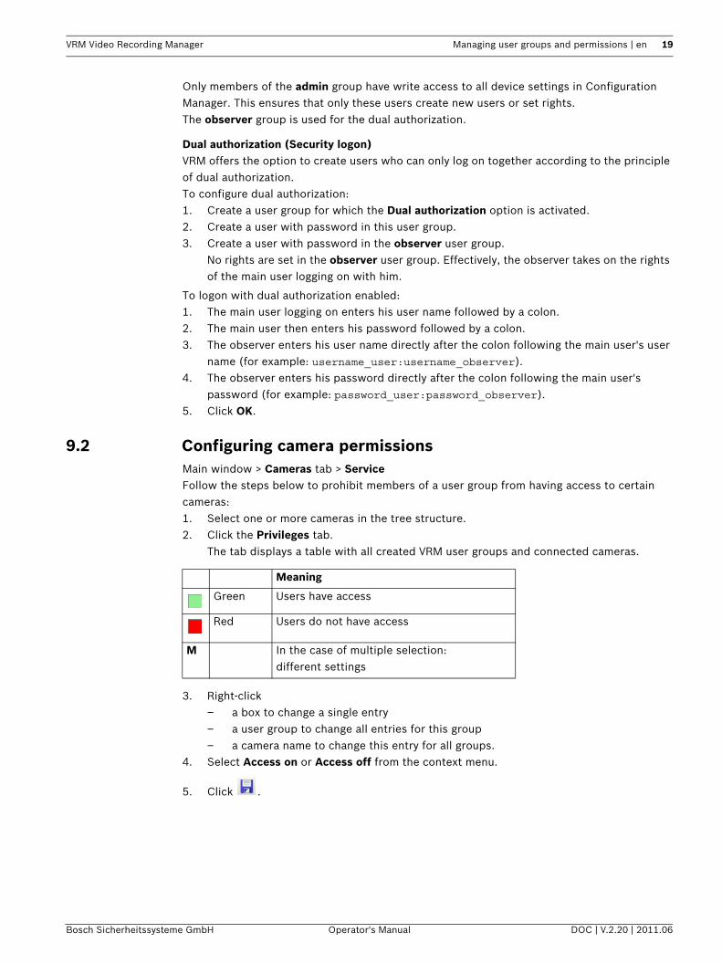
9.2 Configuring camera permissionsMain window > Cameras tab > ServiceFollow the steps below to prohibit members of a user group from having access to certain cameras:1. Select one or more cameras in the tree structure.2. Click the Privileges tab.
The tab displays a table with all created VRM user groups and connected cameras.
3. Right-click – a box to change a single entry– a user group to change all entries for this group– a camera name to change this entry for all groups.
4. Select Access on or Access off from the context menu.
5. Click .
Meaning
Green Users have access
Red Users do not have access
M In the case of multiple selection:different settings
20 en | Configuring Automatic Network Replenishment VRM Video Recording Manager
DOC | V.2.20 | 2011.06 Operator's Manual Bosch Sicherheitssysteme GmbH
10 Configuring Automatic Network Replenishment
Main window > Devices tab > Expand Devices > > Recording > Recording Management VRM supports Automatic Network Replenishment (ANR) for devices with firmware version 4.0 or above. ANR technology gives the VRM system optimum protection against data loss in the event of network failure. The network failure is registered immediately if the failure is longer than 10 seconds. Once the network connection has been restored, gaps in the recording are automatically filled. The ANR technology accurately inserts the missing parts into the gaps in the VRM system recording using the local recording of the device in question.Cameras in ANR mode save the recording locally on transient LUNs. After a network failure between a camera and the VRM system, the data stored locally during the failure is automatically transferred to the VRM system.Whenever VRM server can establish a network connection to an ANR device, the data saved there is transferred to the iSCSI system managed by VRM.For devices with firmware 4.10 or greater, you can use ANR on iSCSI targets that are connected directly to a BVIP device.Note: A failover VRM server cannot perform ANR jobs.Note: A VRM server can perform maximum 3 ANR jobs simultaneously.Note: If you configure multiple ANR jobs for 1 device (for example with 4 channels), these jobs are performed one after the other. This avoids overload of the device.Note: Ensure that disk space available on the transient LUN is sufficient for the recordings made during the time the network connection is missing.The device working in ANR mode must already be added to the system.Follow the steps below to configure a device that works in ANR mode:1. Under Management mode, select the Recording 1 managed by VRM - Recording 2 used
for ANR option.2. In the Local Media tab, select the storage medium on which local recording should take
place. Depending on the device, different media will be available.3. Click Add to add the selected medium to the disk space in use.4. Ensure that the Rec. 2 option is activated for a storage medium in the list; otherwise,
ANR is not possible.Click to ckeck Overwrite older recordings – Recording 2.
Note: To remove a medium from the list of available storage media, select the device and click Remove.
5. Select the associated target in the Storage Systems main node and ensure that Transient type is set for the corresponding LUN.
VRM Video Recording Manager User interface | en 21
Bosch Sicherheitssysteme GmbH Operator's Manual DOC | V.2.20 | 2011.06
11 User interfaceThis chapter contains information on all VRM related pages available in Configuration Manager.
11.1 Device Allocator dialog boxMain window > Tools menu > Device Allocator... command > Device Allocator dialog box
Installed devices / Allocated devicesAll IP cameras and encoders detected in the network are displayed on the left pane, while those allocated to the VRM system appear on the right pane. You can sort the list entries by clicking the relevant table header.
Recordings managed by VRMClick to clear if you want the recordings of this device not be managed by VRM. This is for example the case when you want to configure ANR for this device.
Click to get step-by-step instructions:– Section 7.3 Allocating detected devices, page 13
11.2 Failover VRM Server information
Main window > Devices tab > > General > Unit Access tab
Failover VRM Server informationIP address failover serverFor Archive Player only: Type in the IP address of the failover VRM that you have configured on the VRM Settings tab. This ensures that Archive Player has access to the recordings of the failover VRM.
11.3 VRM Settings tab
Main window > Devices tab > > General > VRM Settings tab
VRM Server nameType a name that is displayed in the device tree of Bosch Video Client.
Server initiator nameDisplays the iSCSI initiator name of VRM Server.
NOTICE! Detailed information about the configuration options for a device can be found in the relevant device documentation and the online Help in the relevant Web browser view.
NOTICE! Some settings (for example in the Date/Time tab) can only be changed if the device is not currently recording.If necessary, stop any recordings before making changes.
22 en | User interface VRM Video Recording Manager
DOC | V.2.20 | 2011.06 Operator's Manual Bosch Sicherheitssysteme GmbH
System-wide CHAP passwordEnter the password that you have configured in the iSCSI storage device. The CHAP password is valid for the VRM and is sent to all devices automatically. Replay clients do not need additional configuration.
Use as failover server / Master server IP address / PasswordYou can set up a computer as the master server, provided that VRM Server is started on it, and set up another computer as a failover server. The configuration settings of the master server are then synchronized on the failover server. If the master server fails, the failover server automatically takes over the management of the VRM system.
Secondary target block allocation [GB]Enter the number of 1 GB storage blocks that are allocated to a device on the failover iSCSI target (secondary target). The minimum number of blocks for each device allocated to the secondary target is eight. When carrying out this step, note that each VIP X1600 module is counted as an individual device.The retention time configured in the system also applies to secondary target blocks.The number of secondary target blocks for a device should be selected in such a way that there is enough disk space to continue recording for the required length of time if the primary target fails. Depending on the bit rate, you can assume that one block is sufficient for approximately one hour of recording.Blocks should remain free on the secondary target as a buffer. These are used by the VRM system if the blocks allocated to a device are insufficient.Calculation example:– Storage capacity of the failover iSCSI target: 5024 GB– Number of allocated VIP X1600 devices: 140 (each occupied with four modules)– Failover block allocation: 8 (minimum)– Resulting number of allocated failover blocks:
140 x 4 x 8 = 4480– Resulting number of free failover blocks:
5024 - 4480 = 544A buffer of 544 GB remains for recordings in case of a failover; this buffer is also available to the allocated devices if required.
Block reservation for VRM Server downtime (days)Enter the number of days that the assigned encoders will be recorded although the VRM Server is down.For example, if you set 4, the encoders will be recorded during approximately 4 days of VRM Server downtime.If your system has encoders with low bit rate, you can significantly reduce the pre-allocated disk space.
Recording preferences modeAutomatic: Load balancing is configured automatically. Each encoder is automatically assigned 2 iSCSI targets and blocks on these 2 iSCSI targets are assigned to the encoder.Manual: You can configure load balancing manually in the traditional recording mode.Section 11.11 Recording Preferences tab, page 28
Sanity check period (days)Move the slider to configure the required time period. After this time period the iSCSI target is checked and blocks are reassigned if needed.
VRM Video Recording Manager User interface | en 23
Bosch Sicherheitssysteme GmbH Operator's Manual DOC | V.2.20 | 2011.06
Click to get step-by-step instructions:– Section 8 Configuring a failover server, page 17– Section 7.9 Configuring manual recording mode, page 16– Section 7.10 Configuring automatic recording mode, page 16
11.4 User Management tab
Main window > Devices tab > > General > User Management tabAllows you to configure user groups and users used for configuring VRM Server.
Add...Click to display the User or Group dialog box.
Edit...Click to display the User or Group dialog box.
RemoveClick to display the Remove User or Remove Group dialog box.
VRM Rights tabClick to configure rights for a selected user group.
PasswordType in a password for the selected user.
ConfirmConfirm the password.
Click to get step-by-step instructions:– Section 9.1 Configuring users and user groups, page 18
11.4.1 User dialog box
Main window > Devices tab > > General > User Management tab > Add... buttonor
Main window > Devices tab > > General > User Management tab > Edit... button
NameType in a name for the user.
PasswordType in a password for the user.
Confirm passwordConfirm the password.
GroupSelect a group to assign this user to the selected group.
Click to get step-by-step instructions:– Section 9.1 Configuring users and user groups, page 18
11.4.2 Group dialog box
Main window > Devices tab > > General > User Management tab > Add... button
24 en | User interface VRM Video Recording Manager
DOC | V.2.20 | 2011.06 Operator's Manual Bosch Sicherheitssysteme GmbH
or
Main window > Devices tab > > General > User Management tab > Edit... button
NameType in a name for the user group.
PTZ control priority (for VIDOS only)Enter a number to configure the priority for the PTZ control for each user of this user group. 1 means lowest priority, 100 means highest priority. 0 means no access.
Click to get step-by-step instructions:– Section 9.1 Configuring users and user groups, page 18
11.5 iSCSI System Access tab
Main window > Devices tab > Expand > Expand Storage Systems > Desired iSCSI
device: > iSCSI System Access tab
Configuration passwordEnter the password that enables the VRM system to access the iSCSI storage system for configuration purposes.
SNMP IP addressIf the RAID system has its own port for SNMP requests, enter the relevant SNMP IP address here.
11.6 Default Configuration tab
Main window > Devices tab > Expand > Expand Storage Systems > Desired iSCSI
device: > Default Configuration tabOnly displayed if the device is a iSCSI storage systems supported by Bosch, for example NetApp.
Capacity [MB]Information on the total capacity of the storage system.
Number of LUNsYou can change the number of LUNs.
Initialization status (%)Additional information is displayed during initialization. When initialization is complete (100%), you will also have the opportunity to delete all LUNs again.Note: On NetApp storage systems, it can take several hours before LUNs are fully deleted. During that time, the total capacity of newly created LUNs can be reduced. You can only create new LUNs with full capacity after the old LUNs have been completely deleted.
CAUTION! If you change the number of LUNs, the entire iSCSI system is reorganized and any sequences saved on the system are lost.Therefore, before making changes, check the recordings and back up any important sequences.
VRM Video Recording Manager User interface | en 25
Bosch Sicherheitssysteme GmbH Operator's Manual DOC | V.2.20 | 2011.06
RAID-DP (reliability focused)This option is only displayed for NetApp DSA-N2B20.Activate this option if you do not wish to use the specified RAID type RAID-4, but would prefer to use the more reliable RAID type RAID-DP.
11.7 Load Balancing tab
Main window > Devices tab > Expand > Expand Storage Systems > Desired iSCSI
device: > Load Balancing tabSet the upper limits for the permitted bit rate and the number of simultaneous iSCSI connections for each iSCSI system. If these limits are exceeded, data is no longer be written to the iSCSI system and is lost. For supported systems (for example Bosch RAID, NetApp, DLA), use the default values. For another device see the documentation of this device. Start testing with small values.Note: The values entered on the Load Balancing tab are only valid if the All or Restricted option is selected.
Soft limitEnter a value smaller or equal to the value in the Hard limit field. If the values are not exceeded, data is written to the iSCSI device without internal reorganization. If they are exceeded but smaller than the values in the Hard limit field, the data is internally reorganized before writing.
Hard limitThese values represent a security margin in relation to the soft limit values. If the write accesses are in this range, internal allocation of addressed blocks must be reorganized. This does not affect the current recording. If this value is also exceeded, the recording is interrupted for a few seconds and the internal allocation of addressed blocks is reorganized.If the system as a whole does not provide sufficient bandwidth or iSCSI connections for the allocated devices, this can result in recordings being impossible on a regular basis. If this is the case, increase the available overall bandwidth and/or the number of possible iSCSI connections by adding further storage systems, or reduce the number of cameras recording on the iSCSI system.
11.8 Target Settings tab
Main window > Devices tab > Expand > Expand Storage Systems > Expand
iSCSI System Access > > Target Settings tab
FormatActivate this option for each LUN that you wish to reformat. You can also use the Select All and Deselect All buttons.
TypeDefine the LUN type:– Standard
Standard VRM LUN for saving and replaying recordings.
– Read onlyRecordings can be replayed from the LUN, but no new data will be written to the LUN.
26 en | User interface VRM Video Recording Manager
DOC | V.2.20 | 2011.06 Operator's Manual Bosch Sicherheitssysteme GmbH
If (format) is displayed after the selected type, the LUN is automatically formatted when this type is selected.There is another LUN type, which cannot be defined on this tab. This type is automatically allocated to each LUN for which the recordings are not managed by the VRM system:– Backup
LUN is used for backups with Archive Player.
Not supported for Bosch Video Client < V.1.2.
– TransientLUN with transient data, for example on the local storage medium of devices in ANR mode. Transient memories are managed locally by the device rather than by VRM. Transient LUNs appear under Unmanaged in the tree structure.
StatusShows the current process. Ready means that the LUNs are available.
SetAll changes are saved and the necessary processes (type changes, formatting) are started. Progress information is displayed in the Status column.
11.8.1 LUN Assignment dialog box
Main window > Devices tab > Expand > Expand Storage Systems > Expand
iSCSI System Access > > Target Settings > LUN Assignment...Add individual LUNs to the system and configure them. You can add a backup LUN that has been used in another VRM system. If the LUN was formatted with VRM 2.10 or later, it is automatically detected as a backup LUN.The type of a LUN types (standard/read-only/backup) is stored on the LUN itself, so if configuration is lost, the LUN can be added without risk of data loss. The correct type of the LUN is read out and is set correctly.
SourceLists the LUNs that are available for this target and have not yet been added to the system.
VRM SystemLists the LUNs that have already been added to the system.
Restore databaseActivate this option if you want to retain any existing data, for example recordings from another VRM system, when the LUN is added. This data is evaluated and any cameras referenced in it are added to the current VRM system, if necessary.
11.9 Recording Management tab (only firmware version 4.0 or later)
Main window > Devices tab > Expand Devices > > Recording > Recording Management Before you make any changes, you must stop any active recordings. Active recordings are
indicated by an icon: If you hover the pointer over the icon, detailed information about the active recordings are displayed. To stop the recordings, click the Recording Scheduler tab and click Stop Recording.
VRM Video Recording Manager User interface | en 27
Bosch Sicherheitssysteme GmbH Operator's Manual DOC | V.2.20 | 2011.06
Recordings manually managedThe recordings are managed locally on this encoder. All relevant settings must be carried out manually. The encoder is removed from the VRM system.
Recording 1 managed by VRMThe recordings of this encoder are managed by the VRM system.
Recording 1 managed by VRM - Recording 2 used for ANRRecording 1 of this encoder is managed by VRM, recording 2 is stored locally on the encoder for ANR. For more details, refer to: Section 10 Configuring Automatic Network Replenishment, page 20.
iSCSI Media tabOnly available if you click Recordings manually managed. Click to display the available iSCSI storage connected to this encoder.
Local Media tabOnly available if you click Recordings manually managed. Click to display the available local storage on this encoder.
AddOnly available if you click Recordings manually managed. Click to add a storage device to the list of managed storage media.
RemoveOnly available if you click Recordings manually managed. Click to remove a storage device from the list of managed storage media.
Overwrite older recordingsIf activated, the oldest recordings are deleted as soon as the medium is full. A loop recording process occurs.If not activated, nothing more is recorded on the disk once it is full.In the case of encoders in ANR mode, ensure that the local storage is sufficient for the recordings that will occur during the time the network connection is missing.
Click to get step-by-step instructions:– Section 7.8.1 Configuring local storage (firmware version 4.0 or later), page 15
11.10 Storage Medium tab (only firmware version up to 3.5)
Main window > Devices tab > Expand Devices > > Recording > Storage Medium The Storage Medium tab is displayed for encoders with firmware 3.5 and older. Once you have allocated an encoder to the VRM system, the storage medium type is automatically set to VRM if iSCSI storage systems have already been allocated and the encoder is not actively recording on another medium (for example a CompactFlash card).Partitioning is performed and managed by the VRM system. For this reason, under Partition only a sequential number and specified name are shown for each camera that is connected to the device, as well as a fixed partition size of approx. 1 GB. This partition size represents the smallest unit that the VRM system can manage. The currently available disk space for recordings of the sender depends on how much total storage you have included in the system under Storage Systems and whether this has been restricted for the sender under Recording Preferences.You must call up the Storage Medium tab if you want to make alarm recordings with the VRM system.
28 en | User interface VRM Video Recording Manager
DOC | V.2.20 | 2011.06 Operator's Manual Bosch Sicherheitssysteme GmbH
The encoder uses a special recording mode during alarm recording for optimal usage of storage capacity: as soon as a time gap for alarm recording begins, a recording is continuously made on one segment, which is the size of a complete alarm sequence (pre- and post-alarm time).This segment in the partition works like a ring buffer and is overwritten until an alarm is actually triggered. Recording occurs on the segment only for the duration of the preset post-alarm time and a new segment subsequently used in the same way.
Click to get step-by-step instructions:– Section 7.8.2 Configuring alarm tracks (firmware up to 3.5x), page 15
11.11 Recording Preferences tab
Main window > Devices tab > Expand > Expand Devices > > Recording > Recording Preferences tabThe Recording preferences page is displayed for each encoder. This page only appears if a device is assigned to a VRM system.Note: When you configure the automatic recording mode, you cannot configure any settings here.Section 11.3 VRM Settings tab, page 21
ModeSelect the required option.– All
The VRM system discovers all available and configured iSCSI targets and assigns the available capacity automatically. If a target fails or memory capacity is used, another target is selected automatically. In this case, you cannot enter targets on the tab.
– RestrictedRecordings are stored primarily to the targets entered here. Primary target and secondary target are used equivalently.
If no disk space is available on either of the targets entered, other storage blocks of the VRM system are used until there is space available again on the entered targets.
– FailoverRecordings are saved only to primary target. If it is not possible to save to this target, the recording will be saved to the target entered under secondary target.
A failure situation is reached if the primary target does not provide storage blocks due to whatever reason: system down, network error, no capacity left.
You can leave the second list empty. In this case no failover is possible but the number of required iSCSI sessions is reduced.
– PreferredRecordings are saved to the entered targets in the specified sequence. For this, enter both a primary and a secondary target. The secondary target is only used while the primary target has no storage capacity available.
Only if these targets are not available, the recordings will be distributed across other targets.
CAUTION! Alarm tracks must be set up in the partition for alarm recording.
VRM Video Recording Manager User interface | en 29
Bosch Sicherheitssysteme GmbH Operator's Manual DOC | V.2.20 | 2011.06
Primary targetSelect the entry for the required target, if you have selected a setting other than All under Mode.
Secondary targetSelect the entry for the required target if you have selected Failover under Mode. If you have set Restricted, Failover, or Preferred, entering a secondary target is optional. Restricted and Preferred without a second target are identical.
11.12 Retention time tabMain window > Cameras tab > Select a cameraNote: If the Cameras tab is not displayed, enable it: Section 6.3 Enabling the Cameras tab, page 11You can specify the retention time for recordings for each camera:
Maximum retention time (days)Recordings are automatically deleted as soon as this value and the minimum retention time are exceeded.The maximum retention time is valid also for already existing recordings.The value O means infinite. In this case VRM Server tries to keep the recordings according to the minimum retention time, for example 10 days. But if enough storage is available, older recordings can exist, for example 20 or more days.VRM Server checks all 60 minutes, whether recordings are available that has exceeded the maximum and the minimum retention time. This data is deleted.Minimum retention time (days)Recordings cannot be deleted until this value is exceeded.This value is stored when the data is written to the disk. It cannot be changed afterwards. If changed, only new recordings are affected.Note: If you configure a minimum retention time that needs more disk space than available, recording stops until the configured minimum retention time is exceeded.LockActivate this option to avoid accidental changing of the retention time values.
11.13 Privileges tabMain window > Cameras tab > ServiceThe Privileges tab is displayed for each camera. This is where access privileges are granted for the camera in line with the VRM user groups. This is where you can revoke access privileges to this camera for members of a user group. These users will then no longer see the camera in question in the camera lists in VRM Monitor and Bosch Video Client. They do not have access to the camera itself or to the associated recordings.In the default setting, all user groups have access privileges to all cameras.
11.14 Advanced tab
Main window > Devices tab > > Service > Advanced tabActivate the different logs for VRM Server and Configuration Manager, and specify the retention time for log files in days.
30 en | User interface VRM Video Recording Manager
DOC | V.2.20 | 2011.06 Operator's Manual Bosch Sicherheitssysteme GmbH
The log files for VRM Server are stored on the computer on which VRM Server has been started, and can be viewed or downloaded with VRM Monitor.The log files for Configuration Manager are stored locally in the following directory:C:\Documents and Settings\<User>\My Documents\Bosch\Video Recording
Manager\Log
Complete memory dump fileOnly activate this option if necessary, for example if the Technical Customer Service team requests a complete summary of the main memory.
Telnet supportActivate this option if access with the Telnet protocol is to be supported. Only activate if necessary.
11.15 License tab
Main window > Devices tab > > Service > License tabProvides information on your license.
CAUTION! Extensive logging requires considerable CPU power and HDD capacity.Do not use extensive logging in continuous operation.
VRM Video Recording Manager Index | en 31
Bosch Sicherheitssysteme GmbH Operator's Manual DOC | V.2.20 | 2011.06
IndexAActivation key 9admin 18Alarmaufzeichnungen 27ANR 20ANR mode 20application windows 21authentication 14Authorization number 9authorize 14Automatic Network Replenishment 20automatic recording mode 22, 28CCamera
ANR mode 10, 20available 10busy 10faulty 10offline 10protected 10
CHAP password 22Clearing allocations 14Configurator
installation 7DDevice
ANR mode 10available 10busy 10faulty 10offline 10protected 10
Device allocator 13, 14, 21EEgg timer 10IInstallation code 9iSCSI password 22iSCSI system
adding 12, 17configuring 12, 17removing 12
LLicensing 9Logging 29logon 14LUN
adding 26allocating 12, 26backup 26removing 12transient 20
Mmanual recording mode 22, 28Master server 22PPadlock 10
Partitioning 27permanent authentication 14Program start 11Rrecording mode
automatic 22, 28manual 22, 28
Recording preferences 16, 28Rights 29SSaving (settings) 10Server
installation 7Server initiator name 21Server name 21Setting up alarm tracks 15Storage management 27TTransient 26UUsers 18VVRM Monitor 6
32 en | Index VRM Video Recording Manager
DOC | V.2.20 | 2011.06 Operator's Manual Bosch Sicherheitssysteme GmbH


Bosch Sicherheitssysteme GmbHWerner-von-Siemens Ring 1085630 GrasbrunnGermany
© Bosch Sicherheitssysteme GmbH, 2011