vrf and k-12 schools
TRANSCRIPT

VRF and K-12 Schools
A Guide to the Design and Use of LG VRF HVAC
Systems for Kindergarten-12 Grade
(K-12) Schools

VRF and K-12 Schools
LG Air Conditioning Systems Page 2 © LG Electronics U.S.A., Inc. 2016
Proprietary Data Notice
This document, as well as all reports, illustrations, data, information and other materials are the prope rty of LG Electronics U.S.A., Inc., and are disclosed by LG Electronics U.S.A., Inc., only in confidence.
Note: Legal Disclaimer: All material presented, referenced, and provided herein is for general informational and/or educational purposes; and is not intended to provide or replace the independent judgment of a qualified engineer and/or HVAC design professional nor does it in any way constitute system application advice. Always seek the advice of a qualified engineer and/or HVAC design professional because reliance on any information provided herein absent the input of said professionals is solely at your own risk.
For continual product development, LG Electronics U.S.A., Inc., reserves the right to change specifications without notice.
For additional technical materials including submittals, engineering data books, and catalogs visit www.lg-vrf.com.

VRF and K-12 Schools
LG Air Conditioning Systems Page 3 © LG Electronics U.S.A., Inc. 2016
Table of Contents
Purpose .............................................................................................................................................4
Heat Recovery ...................................................................................................................................5
Why LG VRF? .....................................................................................................................................7
Installation .................................................................................................................................................... 7
LG VRF Benefits ............................................................................................................................................ 7
Efficient Design ............................................................................................................................................. 7
Zoned Comfort Control & Dehumidification ............................................................................................... 8
Sustainability ................................................................................................................................................ 8
Quiet Operation ........................................................................................................................................... 8
Controls ........................................................................................................................................... 10
Why Is VRF a good application for a K-12 School? ............................................................................. 12
Is VRF too complicated? ................................................................................................................... 14
Is a VRF system more expensive than other conventional systems? ................................................... 14
What about Outside Air? .................................................................................................................. 16
What about the Gym HVAC? ............................................................................................................ 17
What about ASHRAE Standards 15, 34, 55, 62.1 and VRF? ................................................................. 20
How does VRF compare to Water Source Heat Pump (WSHP) Systems for K-12? ................................ 24
VRF vs. WSHP Systems: .................................................................................................................... 28
What about using Ground Source Heat Pump (GHP) Systems for K-12 Schools? ................................. 30
Beware of Marketed EER .................................................................................................................. 37
VRF vs. GHP Systems: ....................................................................................................................... 39
Use LG Multi V Water IV Instead of WSHP/GHP ................................................................................ 41
LG Hydro Kit..................................................................................................................................... 49
What about the use of Air Cooled Chilled Water Systems for K-12 Schools? ....................................... 52
Operating Cost Examples: ................................................................................................................ 54

VRF and K-12 Schools
LG Air Conditioning Systems Page 4 © LG Electronics U.S.A., Inc. 2016
Purpose The purpose of this document is to provide engineers, designers and decision makers with information on how to apply LG Variable Refrigerant Flow (VRF) systems in their designs for the HVAC systems in kindergarten through 12th grade (K-12) schools, the benefits of VRF that make it well suited for K-12 school HVAC designs and how VRF stacks up against other conventional school HVAC systems such as Water Source Heat Pumps (WSHPs), Ground Heat Pump (GHP) Systems, and Air Cooled Chilled Water Systems (CHW). As shown below, R410A refrigerant, the heat transfer medium used in LG VRF systems, can contain the greatest energy per pound compared to air and water, which is the transfer medium for conventional HVAC systems. Also, when comparing molecular characteristics, one molecule of R410A refrigerant is smaller than air and water. This capacity to transfer more energy at a smaller size is the reason LG VRF systems are so energy efficient while using limited physical space and thereby have the lowest life cycle cost compared to other HVAC systems. This makes VRF a good choice for schools construction where a district has limited funds and requires zoned control. Also, what makes an advantage of LG VRF systems for use in K-12 schools is the heat recovery option. Heat recovery uses rejected heat from class rooms in cooling mode to heat classrooms that need heating. This makes for an efficient application. Water Source Heat Pump Systems (WSHP) do this as well, but they require the routing of bigger water pipes throughout the school and WSHP systems require pumps to circulate the water. VRF systems do not require additional pumps to circulate the refrigerant. The LG Multi V IV system combines the best features of heat recovery VRF systems. Condensate drains are not required for Multi V Heat Recovery units. Heat recovery units that can serve 2, 3, or 4 zones are strategically placed in series or in parallel to maximize piping reach while minimizing material and labor costs. Piping, fittings, branches, headers, hangers, insulation, joints, nitrogen, and labor hours can be greatly reduced resulting in significantly lower installed costs.
85.38 Btu/h Energy
per lb. R-410a
Water
8.88 Btu/h Energy
per lb. Water
R-410A
0.48 Btu/h Energy
per lb. Air
Air

VRF and K-12 Schools
LG Air Conditioning Systems Page 5 © LG Electronics U.S.A., Inc. 2016
Heat Recovery It can be seen that the LG heat recovery layout offers many advantages over other manufactures due to the following highlights noted below:
Configured for fully independent heating and cooling
Parallel or series configuration
Ports are closer to the indoor units they serve which reduces piping costs
No heat recovery unit condensate drains saves material costs
Smaller number of Y-Branch brazes reduces field install labor

VRF and K-12 Schools
LG Air Conditioning Systems Page 6 © LG Electronics U.S.A., Inc. 2016
• Configured for fully independent heating
and cooling Series configuration only
Lengthy home run piping May require heat recovery unit condensate
drain
Configured for fully independent heating and cooling
Parallel configuration only
Many heat recovery units for independent heating and cooling
Numerous joints

VRF and K-12 Schools
LG Air Conditioning Systems Page 7 © LG Electronics U.S.A., Inc. 2016
Why LG VRF?
The benefits are numerous: modern style, mirror units for interior designers, less piping for installers and energy efficiency for owners. LG is among the industry leaders in low sound levels, so units are quiet and can be installed where sound is an issue. LG manufactured inverter scroll compressors optimize system energy efficiency and are certified using AHRI Standard 1230. Other benefits include the following:
Installation LG VRF system components are modular, small and lightweight compared to conventional HVAC system components. They are typically installed without the use of a crane, saving substantially on installation cost. The unit modularity supports building a system over time to serve floors as a building is occupied. The low weight can reduce the need for structural reinforcement to support more massive equipment. The compressor units are typically installed outdoors and do not need a machine room or mechanical penthouse reducing noise within the occupied space.
LG VRF Benefits Your project can realize significant benefits by using LG's VRF Technology. Efficiency and modern modular design are just the beginning. The modular design of VRF results in superior energy savings giving occupants the choice to air condition or heat only the zones in use. A VRF system provides exceptional dehumidification and temperature control by rapidly adapting to changing loads as seen in a school environment.
Efficient Design Without using large distribution ducts, the LG Multi V system removes losses that are unavoidable in other systems. In addition, the use of optimized scroll or rotary compressors, specially designed heat exchangers, and inverter technology, the Multi V system minimizes energy consumption to levels previously unattainable by non-VRF systems. The modular design offers comfort on demand allowing

VRF and K-12 Schools
LG Air Conditioning Systems Page 8 © LG Electronics U.S.A., Inc. 2016
the choice to use the system only in the zones where it is needed further promoting reduced energy consumption.
Zoned Comfort Control & Dehumidification With the use of inverters and dual compressor outdoor units, the LG Multi V system offers superior load matching, preventing constant cycling or large temperature swings. Tight temperature control through precise load matching ensures maximum comfort, efficient operation, and superior dehumidification. The modular design of VRF results in superior energy savings giving occupants the choice to air condition or heat only the zones in use. The LG Multi V offers individual zoning to ensure occupants comfort.
Sustainability The architectural and engineering community is adopting a balanced design approach that considers energy and water consumption, repetitive maintenance costs, the impact of development on the environment, and the building’s initial cost as equally important factors in developing high performance, sustainable buildings that will increase building value. LG’s Multi V VRF systems help achieves points for sustainability programs. The USGBC has developed holistic design standards for constructing new and retrofitting existing buildings known as LEED® - Leadership in Energy and Environmental Design. The Multi V variable refrigerant flow air conditioning systems are engineered for sustainable green buildings and provide opportunities for designers to claim numerous LEED® prerequisites and points.
Quiet Operation
With LG VRF, Students can work without distraction. With indoor units that can operate at sound levels as low as 23dB (A) and outdoor units that operate as low as 50dB (A) and lower with night quiet operation, LG Multi V creates a comfortable environment so quiet it’s almost undetectable. For additional sound level control, a night quiet mode can be set to limit fan speed during off peak hours.

VRF and K-12 Schools
LG Air Conditioning Systems Page 9 © LG Electronics U.S.A., Inc. 2016
“The importance of quality room acoustics in schools has been recognized by Educators and School Architects as evidenced by the new standard, ANSI S12.60, "Standard for Classroom Acoustics." This standard was recently created to provide acoustical criteria for those involved in school building design.” “Designing to reduce noise generated by the HVAC system is also critical for creating a quiet space. The more quiet the space, the better the students hear and understand.” http://www.kineticsnoise.com/schools/index.html

VRF and K-12 Schools
LG Air Conditioning Systems Page 10 © LG Electronics U.S.A., Inc. 2016
Controls Controls are an integral part of LG VRF systems. LG VRF systems incorporate sophisticated controls and automation; control of the complex refrigerant system requires this. The many control points of the refrigerant system are monitored resulting in easy trouble-shooting, and automatic diagnostics of the refrigerant system. Control of the internal refrigerant management has been optimized for the system’s overall efficiency, longevity, and comfort to the space. Detailed system diagnostics of internal refrigerant management can be viewed through LG’s Mobile LGMV software. LG’s controls allow users to control and monitor the system for individual zone comfort. Utilizing LG’s individual zone remote controllers, occupants can control their individual zone, central controllers allow building managers to control the entire VRF system, and BACnetTM and LonWorksTM gateways allow the Energy Management System to integrate the VRF system with other systems within the building. * BACnet is a registered trademark of ASHRAE * LonWorks is a trademark of Echelon Corporation
Comfort LG indoor units can be sized to serve small spaces with independent temperature control, such as individual private offices or classrooms. With capability to provide heating or cooling and modulation of the compressor, a narrow temperature range can be maintained. Anecdotal information, and results of one informal field study, indicates that attention needs to be paid to ensure that controls are working to maintain stable temperature control without alternating heating and cooling. Commissioning of zone temperature control is recommended.
Component to component direct communication
VRF and K-12 Schools
LG Air Conditioning Systems Page 11 © LG Electronics U.S.A., Inc. 2016
Space Requirements
Transferring heat through refrigerant piping requires a lot less space than ductwork. This makes LG VRF systems well suited to retrofits, particularly historic buildings that may not have any ductwork or cooling. However, if outside air requirements are not met by natural ventilation already, then ductwork of sufficient size to provide code-required ventilation will need to be added. In new buildings, the low space requirement can result in reduced floor-to-floor height, providing initial cost savings.
Maintenance Regular maintenance of LG VRF systems consists of changing filters and cleaning coils for the fan coil units. This level of maintenance is not substantially different than for other zonal systems, such as conventional water-source fan coils and split systems. Maintenance of the compressor unit is minimal, and there will be significant maintenance savings for this part of the system compared to chilled water and hot water plant equipment.
LG Inverter Scroll
There are several ways to modulate the cooling capacity in compressor air conditioning and heating systems. The most common in air conditioning are the following: on-off cycling, hot gas bypass, use or not of liquid injection, manifold configurations of multiple compressors, mechanical modulation (also called digital) and inverter technology.
• On-off cycling: results in switching off the fixed-speed compressor under light load conditions and could lead to short cycling and the reduction in compressor lifetime. Efficiency of the unit is reduced by pressure cycling and transient losses. The turndown capacity is 100% or 0%.
• Hot gas pass: involves injecting a quantity of gas from discharge to the suction side. The compressor will keep operating at the same speed but thanks to the bypass, the refrigerant mass flow circulating with the system is reduced and thus the cooling capacity. This naturally causes the compressor to run uselessly during the periods where the bypass is operating. The turndown capacity varies between 0 and 100%.[1]
• Manifold configurations: several compressors can be installed in the system to provide the peak cooling capacity. Each compressor can run or not in order to stage the cooling capacity of the unit. The turndown capacity is either 0/33/66 or 100% for a trio configuration and either 0/50 or 100% for a tandem.[2]
• Mechanically modulated compressor: this internal mechanical capacity modulation is based on periodic compression process with a control valve, the 2 scroll set move apart stopping the compression for a given time period. This method varies refrigerant flow by changing the average time of compression, but not the actual speed of the motor. Despite an excellent turndown ratio – from 10 to 100% of the cooling capacity, mechanically modulated scrolls have high energy consumption as the motor continuously runs.
• Inverter compressor: uses an external variable frequency drive - to control the speed of the compressor. The refrigerant flow rate is changed by the change in the speed of compressor. The

VRF and K-12 Schools
LG Air Conditioning Systems Page 12 © LG Electronics U.S.A., Inc. 2016
turndown ratio depends on the system configuration and manufacturer. It modulates from 15 or 25% up to 100% at full capacity with a single inverter from 12 to 100% with a hybrid tandem.
A new high side shell innovation offers a more compact size for the same capacity output with greater reliability in cold climates. Multi V IV is AHRI 1230 Certification performance certified. This ensures that you are getting verified ratings.
1. http://www.pipelineandgasjournal.com/bypass-method-recip-compressor-capacity-control
http://www.ishrae.in/journals/2000apr/article02.html
2. http://info.aia.org/aiarchitect/thisweek09/0410/0410p_vrf.cfm
Compact Design VRF offers more indoor zones, less outdoor space. When space or access is at a premium, this equates to significant cost advantages for the owner on large projects.
Longer Piping Distances Owners can reach extra zones further off the same VRF units. This eliminates the need to invest in extra systems and saves on installation.
Energy Modeling LG has provided and updated library curves, modeling guides, white papers, and sample files for customers who use building energy simulation programs such as: eQUEST®, Energy Pro, Trane Trace™ 700, EnergyPlus, Carrier Hourly Analysis Program (HAP), and others.
Why Is VRF a good application for a K-12
School? The VRF system is uniquely suited to address the changing K-12 environment and is rapidly growing in popularity resulting in greater familiarity and an increasing knowledge base of technicians who understand the system. VRF offers better individual classroom control and comfort and increased energy savings over conventional HVAC systems for K-12 schools.
Stacked LG Water Cooled Units

VRF and K-12 Schools
LG Air Conditioning Systems Page 13 © LG Electronics U.S.A., Inc. 2016
The layout of a school breaks down the building’s total capacity into zones or classrooms typically between 1-1/2 to 3 tons (excluding OA), which is just the right capacity for a VRF system. Each of these classrooms or zones must be able to operate with a widely varying load (as people come and go) and even as an individual zone when the full building may not be occupied. That’s not possible with a traditional air cooled chiller system because the central plant has to turn on the chiller or boiler, and pumps to turn the air conditioning or heating on. With a water cooled chiller, a cooling tower and associated pumps must also be energized. With a WSHP system, pumps and a cooling tower or boiler must be energized to provide air conditioning or heating. So with a conventional air and water cooled chiller and WSHP system, the central plant must run when cooling or heating is needed in any portion of the building. If only one person is working after hours, the central plant for the whole school must run to provide cooling or heating. The second major driving force is energy and water consumption. While air cooled chillers and electric heating systems are reasonably first-cost effective, they are not energy friendly. In the last five years as LEED and other “green” building programs have become the norm, we have seen many school districts change their design strategy to reach higher efficiency goals. A VRF system provides an avenue for school districts to improve energy efficiency without driving construction costs higher and without a substantial water consumption increase.
Example of where VRF can be used in K-12 Schools

VRF and K-12 Schools
LG Air Conditioning Systems Page 14 © LG Electronics U.S.A., Inc. 2016
Is VRF too complicated? There’s a common misperception that VRF is too complicated. The LG VRF system is actually pretty simple. It consists of an indoor fan coil, an outdoor condensing unit, and a Heat Recovery Unit (HRU) when heat recovery is used. The “sophistication” of any HVAC system is in the controls system. This is nothing new for K-12 operations people, who already work with third-party building automation system (BAS) controls providers to program and manage controls for other ‘conventional” systems. The primary difference between a third-party controls system and an LG VRF system is the controls are an integral part of the VRF system. The internal refrigerant management has been optimized for the system’s overall efficiency, longevity, and comfort to the space. The individual zone remote controllers, central controllers, and gateways all communicate across the VRF system requiring minimum setup or configuration.
Is a VRF system more expensive than other
conventional systems?
The installation cost of VRF is actually less than chilled water and WSHP systems when used in the correct application. Because of the high number of separate classrooms or zones, K-12 schools offer an excellent opportunity for VRF applications. In a K-12 school application, each classroom would have one or more separate indoor VRF units providing heating and cooling for the classroom. This allows individual classroom HVAC control. Heat Recovery VRF is also recommended to allow simultaneous operation of heating and cooling. Simultaneous heating and cooling means that the HVAC system in one classroom may provide cooling, while another classroom may be in the heating mode. The heat rejected from the classroom in cooling mode is used to heat the classroom in heating mode. This makes for a very efficient HVAC system. This mode of operation where each classroom has a fan coil unit can also be found on chilled water systems. The difference between VRF and Fan Coil Chilled Water (FCCW) systems is that chilled water systems do not have the ability to do simultaneous heating and cooling unless they have a 4 pipe arrangement where there is a cooling supply and return pipe and a heating supply and return pipe. Also FCCW systems do not use rejected heat from one zone to heat another zone, and thus are not as energy efficient as VRF systems when simultaneously heating and cooling and may not comply with state and local energy codes. WSHP systems can provide simultaneous heating and cooling, but instead of refrigerant, they use water as the medium to transfer the energy. A pound of R410a refrigerant in liquid phase can hold more energy than a pound of water

VRF and K-12 Schools
LG Air Conditioning Systems Page 15 © LG Electronics U.S.A., Inc. 2016
Also FCCW systems require the installation of either an air or water cooled chiller, a cooling tower if the chiller is water cooled, chilled water pumps, cooling tower pumps if water cooled chiller, boilers and boiler pumps, all associated balancing and gate valves, pressure and temperature valves, strainers, flow switches, and service ports, and fan coils for each classroom and all the associated control valves, pressure/temperature ports, ball valves, Y strainer and air vents for the fan coils.
The above is an example of how the installation of a VRF system compares in cost to similar size
Geo Thermal Heat Pump (GHP) system. It can be seen that the VRF system is 38% less than a
comparable GHP system.

VRF and K-12 Schools
LG Air Conditioning Systems Page 16 © LG Electronics U.S.A., Inc. 2016
What about Outside Air? How to handle the outside air load and humidity are among the most important design criteria on a K-12 project. In a K-12 classroom, a dedicated outside air system (DOAS) is the best way to handle outside air and humidity. In any hot and humid climate, the DOAS should decouple the temperature control from the humidity control. The Dedicated Outside Air System (DOAS) should be designed for dehumidification capacity and controlled by a zone level humidity sensor. In a K-12 school, the DOAS would be the primary dehumidification system and the VRF system would be the temperature control system. The best system for this strategy is a DOAS that provides a neutral temperature supply air at 72-75 degrees F, at a humidity ratio of between 40-45 grains of moisture/lb. of dry air. At this low humidity ratio, the ventilation air being delivered to a classroom will dehumidify the ventilation air load and can provide additional drying effect to the humidity sources already in the classroom such as the students and teachers and any other source of moisture. This strategy reduces the condensate in the VRF indoor units and greatly reduces long-term maintenance required for the condensate piping because most of the latent load is taken care of by the DOAS unit. This also increases the efficiency of the VRF system because the remaining cooing load is almost all sensible where the VRF system is most efficient in removing. The below Decoupled Dedicated Outdoor Air System is the preferred way of introducing ventilation air into the school class rooms. The outside ventilation air is introduced into the class rooms separately from the main heating and cooling system. This method prevents problems associated with trying to mix outside air with return air directly at the heating and cooling unit serving the class room. (Typically associated with VAV (variable air volume) systems)
DOAS
Decoupled Dedicated Outdoor air System

VRF and K-12 Schools
LG Air Conditioning Systems Page 17 © LG Electronics U.S.A., Inc. 2016
In a K-12 school, the Dedicated Outdoor Air System (DOAS) optimizes energy savings and performance. The DOAS provides numerous benefits including: • Airflow rate variable from 400 to 2000 CFM • Air handler controller senses high outdoor air humidity and provides dehumidification mode • Reheat coil allows heating of dehumidified air to room neutral temperatures • Flexible design allows matching of outdoor unit to meet local outdoor air design conditions • Web access to air handler controller • Air handler controller connects to laptop computer without special software • Varying outdoor air temperatures can be conditioned using energy efficient LG VRF technology • Available in two models - with electric preheat coil or without electric preheat coil
The unit is provided with an integrated microprocessor-based controller. Remote duct discharge air temperature sensor, outdoor air temperature sensor, and outdoor air humidity sensor for field mounting in the ductwork are shipped loose inside the control cabinet. The field supplied communication cable between the air handler and outdoor units is to be a minimum of 18 AWG, 4- conductor, stranded, and shielded cable (RS-485), terminated via screw terminal on the control boards. The microprocessor control will operate the air handler using one of the five operating modes: • Cooling • Heating • Dehumidification • Ventilation • Defrost Cooling mode is activated when the outdoor air temperature sensor detects temperature increase above the outside air cooling enable set-point. Outdoor unit compressors modulate to meet the cooling demand by the main coil and maintain discharge air temperature set point. Heating mode is activated when the outdoor air temperature sensor detects temperature decrease below the outside air heating.
What about the Gym HVAC? With most Gyms used for after-hours sports games and after school programs, it is typically useful to have the Gym on a separate HVAC system than the classrooms and offices in the school. The HVAC system of choice for Gyms is typically the gas heating/direct expansion (DX) Roof Top Unit (RTU) because it is simple, effective, and well suited for the HVAC requirements of large open spaces like Gyms where tight temperature control is not needed. For integration of control of the VRF system and Gym RTUs, LG can provide an I/O module to allow scheduled on/off of the RTUs through the VRF control system to provide a seamless operation. Another option available to HVAC engineers/designers is the option of using LG’s AHU kit to interface with another manufacturer’s AHU that may be used for the Gym. The benefit of using The LG AHU kit is the use of LG’s VRF condensing unit. The LG AHU kit can be configured for return air or supply air temperature control. Some of the criteria for using the AHU kit include the following: • Minimum coil entering air temperature is 41F for heating mode

VRF and K-12 Schools
LG Air Conditioning Systems Page 18 © LG Electronics U.S.A., Inc. 2016
• AHU coil sizing parameters • Cooling Mode • Suction (evap) temperature for coil sizing is 41~43F • Condensing (liquid) temperature for coil sizing is 110F • Heating Mode • Hot gas temperature at AHU coil is 113F (range is 104~122F) • Recommended coil tube sizes are 3/8” or ½” • Coil volume data is needed from coil manufacturer to calculate refrigerant trim charge amount • Coils larger than 16 tons should be divided into multiple circuits to allow connection of EEV kit
• Heat recovery systems are limited to 8 ton maximum coil size (can only tie 2 HRU ports together) • Pipe sizing rules are same rules as the connected ODU (see ODU Engineering Manual or updated LATS
version) • Maximum recommended combination ratio is 100% • Comm Kits and EEV Kits are not weather proof and must be protected from rain, snow, etc.
For Gymnasium

VRF and K-12 Schools
LG Air Conditioning Systems Page 19 © LG Electronics U.S.A., Inc. 2016
For Gymnasium

VRF and K-12 Schools
LG Air Conditioning Systems Page 20 © LG Electronics U.S.A., Inc. 2016
What about ASHRAE Standards 15, 34, 55,
62.1 and VRF? The American Society of Heating, Refrigerating, and Air Conditioning Engineers (ASHRAE) committees of industry professionals have collaborated to develop voluntary standards that document industry best practices to safely use refrigerants, guidelines to properly ventilate commercial buildings using various technologies, properly control building temperature and relative humidity, as well as design building systems to minimize energy and water consumption.
ASHRAE 15-2013 and ASHRAE 34-2013: Designing for Refrigerant Safety with Multi V
The Standards address the safety and classification of the refrigerant chemical. All LG Multi V systems use R-410A refrigerant. ASHRAE Standard 34-2007 classifies this refrigerant in Safety Group “A1” and a rated as “neither” in the toxicity category titled “highly toxic or toxic under code classification.1” These are the safest ratings given in the Standard to any refrigerant and are the same ratings are given to refrigerants R-22, R-134A, and R-407C.
Of primary concern is the displacement of all oxygen in a room that could lead to occupant asphyxiation in the event of a catastrophic release of the entire system refrigerant charge. The Standard states R-410A has a Refrigerant Concentration Limit (RCL) of 0.026 lbs./ft3. The RCL indicates the allowable volume (by weight) of refrigerant per cubic foot of room volume to avoid escape-impairing effects such as oxygen deprivation, flammability, and cardiac sensitization among others.
The Standard is written to cover a worst case scenario and assumes the complete system charge is dumped into a confined space over a short period of time. If a refrigerant leak occurs, the actual concentration level in the confined space is dependent upon the quantity of refrigerant in the equipment and the volume of air available for dispersion and dilution. The calculated concentration level in each room cannot exceed the RCL (or 50% of the RCL for institutional buildings such as asylums, nursing homes, hospitals and spaces containing locked cells.)
Note 1: This designation does not indicate that R-410A is non-toxic, with high enough concentrations all
refrigerants can be hazardous.
Table 3 - ASHRAE Publications
Standard 15-2013 Safety Standard for Refrigeration
Systems
Standard 34-2013 Designation and Safety Classification
of Refrigerants
Standard 55-2013 Thermal Environmental Conditions for
Human Occupancy
Standard 62.1-2013 Ventilation for Acceptable Indoor Air
Quality
VRF and K-12 Schools
LG Air Conditioning Systems Page 21 © LG Electronics U.S.A., Inc. 2016
ASHRAE 15-2013 and ASHRAE 34-2013 Designing for Refrigerant Safety with LG Multi V (continued)
The total estimated charge of the refrigeration system is calculated using LG’s LATS refrigerant piping design software. Secondly, the designer must determine which zone or room has the smallest cubic volume served by the system. Calculate the volume of air in each area or room using the following guidelines to determine the dimensions of each zone or room.
Non-connecting Spaces: Defined as “where a refrigerating system or a part thereof is located in one or more enclosed occupied spaces that do not connect through permanent openings or HVAC ducts. Where different stories and floor levels connect through an open atrium or mezzanine arrangement, the volume to be used in calculating the refrigerant quantity limit shall be determined by multiplying the floor area of the lowest space by 8.2 ft.”
Ventilated Spaces: Defined as “where a refrigerating system or a part thereof is located within an air handler, an air distribution duct system, or an occupied space served by a mechanical ventilation system, the entire air distribution system shall be analyzed to determine the smallest volume area.”
Closures: “Closures in the air distribution system shall be considered. If one or more spaces of several arranged in parallel can be closed off from the source of the refrigerant leak, the volume(s) shall not be used in the calculation.”
Closure exceptions include smoke and fire dampers or combinations thereof that close only in an emergency not associated with a refrigerant leak and dampers where airflow is never reduced below 10% of its maximum with the fan running.
Plenums: “The space above a suspended ceiling shall not be included in calculating the refrigerant quantity limit in the system unless such space is part of the air supply or return system.”
Supply and Return Ducts: “The volume of the supply and return ducts and plenums shall be included when calculating the refrigerant quantity limit in the system.”
Concentration Calculations
The Standard calculates the concentration as follows: After the zone dimensions are known, calculate the volume of air in the smallest zone and divide by 1000 (Eq 1.) Finally, divide the refrigerant charge in lbs. by the resultant of Eq 1. If the resultant is higher than the allowed RCL as documented in Standard 15-2013, increase the cubic volume of the smallest zone or modify the piping system design.
Refrigerant Concentration (lbs./ft³) =
The resultant must be less than 0.026 lbs./ft3. When applying any standard or regulation in practice, the designer must use some engineering judgment in determining which rooms or areas are connected, non-connected, or ventilated. Use of transfer ducts between rooms, undercut doors, ventilation grilles in doors, using the area above the ceiling as part of the return or supply air path are all methods that can be used to increase the dilution volume of the smallest areas of the building.
ASHRAE 55-2013 - Thermal Environmental Conditions for Human Occupancy
This Standard identifies the factors impacting thermal comfort and identifies the process for developing comfort criteria to assist designers creating comfort in conditioned spaces. The Standard states “this standard specifies the combinations of indoor space environment and personal factors that will produce thermal environmental conditions acceptable to 80% or more of the occupants within the space.

VRF and K-12 Schools
LG Air Conditioning Systems Page 22 © LG Electronics U.S.A., Inc. 2016
The environmental factors addressed are temperature, thermal radiation, humidity and air speed; the personal factors are those of activity and clothing.”
In the past emphasis was put on building structures airtight with little or no control provided to the occupants. Since the green building movement began and the LEED building rating system gained momentum, individual adjustment of comfort parameters such as thermostats and air flow are being considered upfront as part of the overall mechanical system design. To satisfy the minimum requirement for a LEED point credit for thermal comfort, 50% of the occupants must be provided individual control of selected comfort parameters. Another LEED point is available for Thermal Comfort- Design (IEQ credit 7.1) if the HVAC system design complies with Section 6.1.1 of Standard 55-2004.
ASHRAE 62.1-2013 - Ventilation for Acceptable Indoor Air Quality
Publications over the past twenty years have documented that occupant well- being, productivity, and comfort are significantly impacted if the occupied areas are not properly ventilated. It also is well known that properly treating ventilation air raises the building’s overall energy consumption. However, because of today’s medical costs and the cost related to personnel turnover, any premium associated with tempering and cleaning ventilation air has become insignificant. Standard 62.1-2007, known as the indoor air quality (IAQ) performance standard, documents key strategies for maintaining minimum IAQ including limiting the introduction of potential contaminants into the occupied areas originating from outdoor and indoor sources. The document also addresses the proper introduction of outside (fresh) air into the building employing one of two methods: 1) A ventilation rate procedure; and 2) an IAQ compliance procedure.
The ventilation rate procedure prescribes outdoor air quality requirements; treatment procedures that need to be utilized if the outdoor air is deemed contaminated; and the volume of outdoor air that must be introduced to the occupied areas of commercial, institutional, vehicular, industrial and residential buildings. This method has been coined “the dilution solution.” The Standard also addresses reduced outside air volume requirements when used in conjunction with re-circulated air contaminant removal devices.
The IAQ compliance procedure is a performance based design approach in which the indoor air quality in the occupied areas is actively monitored using sensing devices (such as CO2 level sensors). When the IAQ falls below specified levels, the volume of outside air introduced to the building is modified.
There are three methods used for ventilating buildings: 1) mechanical “active” ventilation; 2) natural “passive” ventilation; 3) mixed-mode “active and passive” ventilation.

VRF and K-12 Schools
LG Air Conditioning Systems Page 23 © LG Electronics U.S.A., Inc. 2016
ASHRAE 62.1-2013 - Ventilation for Acceptable Indoor Air Quality (continued)
This summary will concentrate on providing guidance to the designer in applying active mechanical ventilation methods in conjunction with using Multi V variable refrigerant flow equipment. There are four methods of mechanically introducing outside air to individual occupied areas and rooms. They include:
1) From a common outside air inlet, filter and pre-treat the air temperature to room neutral conditions and duct the ventilation air to ceiling or wall registers in each breathing zone.
2) From a common outside air inlet, filter and pre-treat the air temperature to room neutral conditions and duct the ventilation air to ceiling cassette or recessed-ducted Multi V indoor units.
3) From a common (or multiple) outside air openings, duct filtered, untreated ventilation air to ceiling cassette or recessed-ducted Multi V indoor units.
When using the LG Multi V system, the designer must not depend on the indoor unit fans to draw the proper amount of outside air. In all designs, the outside air must be introduced using a separate fan designed specifically for the task.
When considering which of these three methods to use to distribute the outside air to the occupied areas, the designer should employ a design that minimizes potential maintenance costs and operational problems. When these parameters are a priority, Method #1 is preferred, can be used in all applications and in conjunction with any type of Multi V indoor unit. When Method #1 is employed, and the outside air pre-treatment device experiences a filtering, heating, or cooling component failure, the resulting untreated air will be more readily noticed by the occupants who can notify the building engineer of the problem. But more importantly, the failure will less likely impact the Multi V indoor unit operation.
If Method #2 is employed and the outside air is ducted directly to the indoor unit, a failure of the pretreated system could be masked by the Multi V unit changing its operating parameters to compensate for the failure, but could adversely affect the operation of the indoor unit(s). Air stratification, or an entering coil temperature outside the design parameters of the indoor unit will likely cause erratic behavior of the indoor unit microprocessor control.
If Method #3 is employed the adverse effects noted under Method #2 will be engineered into the design and improper system operation is a real possibility. However, Method #3 can be used, with careful engineering analysis, and only in temperate climate areas where, year round, the entering air (mixed air) temperature at the indoor unit coil is within the indoor unit design parameters and proper mixing of the outside air stream with return air occurs. The mixed air load - heating, cooling sensible and latent, must all be considered when sizing indoor units using Method #3.
If using Methods #2 or #3, negative building pressure can impact the indoor unit fan’s ability to pass the proper amount of air over the indoor unit coil, even when the ventilation system supply fan is turned off and the dampers are closed.
References:
American Society of Heating, Refrigeration and Air Conditioning Engineers, Inc. (ASHRAE) Standard 15-2013,
American Society of Heating, Refrigeration and Air Conditioning Engineers, Inc. (ASHRAE) Standard 34-2013,
American Society of Heating, Refrigeration and Air Conditioning Engineers, Inc. (ASHRAE) Standard 55-2013.
American Society of Heating, Refrigeration and Air Conditioning Engineers, Inc. (ASHRAE) Standard 62.1-2013.

VRF and K-12 Schools
LG Air Conditioning Systems Page 24 © LG Electronics U.S.A., Inc. 2016
How does VRF compare to Water Source Heat
Pump (WSHP) (Cooling Tower/Boiler)
Systems for K-12?
A water source heat pump system operates much like a traditional air source heat pump system except that it extracts and dissipates heat by way of water instead of air. Traditional air source heat pumps get their heat from the air outside, as even relatively cold air actually contains a substantial amount of heat.

VRF and K-12 Schools
LG Air Conditioning Systems Page 25 © LG Electronics U.S.A., Inc. 2016
Water source heat pumps work on basically the same principle as air source heat pumps, but they extract heat from a body of water rather than the air. A boiler is used to add heat to the water loop to make the water source heat pumps more effective and efficient because in heating mode as the water loop temperature decreases so does the water source unit’s efficiency. In the summer, water source heat pumps dissipate heat to water. They do this by cycling water through a system of pipes that are routed through a cooling tower. A cooling tower extracts waste heat to the atmosphere though the cooling of a water stream to a lower temperature. The type of heat rejection in a cooling tower is termed "evaporative" in that it allows a small portion of the water being cooled to evaporate into a moving air stream to provide significant cooling to the rest of that water stream. The heat from the water stream transferred to the air stream raises the air's temperature and its relative humidity to 100%, and this air is discharged to the atmosphere. In an open circuit cooling tower the water to be cooled is distributed over a fill pack whilst air is blown or drawn through the packing. A small quantity of the water evaporates and this causes the remainder of the water to be cooled. The cooled water falls into the sump of the tower and the heat extracted from the water is carried out in the leaving air stream. Evaporative condensers or closed circuit evaporative cooling towers have a heat exchanger or coil within the tower instead of a fill pack. Water is distributed over the heat exchange coil and heat is extracted from the refrigerant or primary fluid circulating through the coil by the same evaporative process.The above WSHP system uses a closed circuit cooling tower. Closed circuit cooling towers are preferred for WSHP systems because they completely isolate process cooling fluid from the atmosphere. A closed loop system protects the quality of the process fluid, reduces system maintenance, and provides operational flexibility at a slightly higher initial cost. Of course, you do also need to have access to an appropriate body of water to have a water source heat pump system installed. The impact of water usage is something that should be understood as per the below: “It is important to note that the volume of ground water in storage is decreasing in many areas of the United States in response to withdrawals. If these water-level declines are sustained over time, the effect is often described as ground-water depletion. Among the consequences of ground-water-level declines are increased pumping costs, deterioration of water quality, reduction of water in streams and lakes, and land subsidence. Such negative effects, while variable, happen to some degree with any ground-water use.” http://water.usgs.gov/watercensus/AdHocComm/Background/Ground-WaterAvailabilityintheUnitedStates.pdf With the decline of ground water storage volume, the cost of water will continue to rise. When evaluating any water use HVAC system, this rise in cost should be taken in account.

VRF and K-12 Schools
LG Air Conditioning Systems Page 26 © LG Electronics U.S.A., Inc. 2016
Layout of a Typical WSHP School Wing
To DOAS
Unit
To DOAS
Unit
Fire Dampers
Typical
Outside
Ventilation
Air
Return
Typical
Outside
Ventilation
Air
Supply
Typical
Vertical WSHP
Typical
Supply Duct
Typical
Return Duct
Typical
Water Piping
Typical
Mechanical
Room
Typical
Water Piping
to other
Wings
Cooling Tower
Boiler
Pumps
VRF and K-12 Schools
LG Air Conditioning Systems Page 27 © LG Electronics U.S.A., Inc. 2016
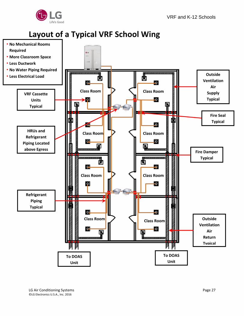
Layout of a Typical VRF School Wing
Class Room Class Room
Class Room Class Room
Class Room Class Room
Class Room Class Room
Fire Damper
Typical
VRF Cassette
Units
Typical
Outside
Ventilation
Air
Return
Typical
Outside
Ventilation
Air
Supply
Typical
To DOAS
Unit To DOAS
Unit
Refrigerant
Piping
Typical
Fire Seal
Typical
• No Mechanical Rooms
Required
• More Classroom Space
• Less Ductwork
• No Water Piping Required
• Less Electrical Load
HRUs and
Refrigerant
Piping Located
above Egress
VRF and K-12 Schools
LG Air Conditioning Systems Page 28 © LG Electronics U.S.A., Inc. 2016
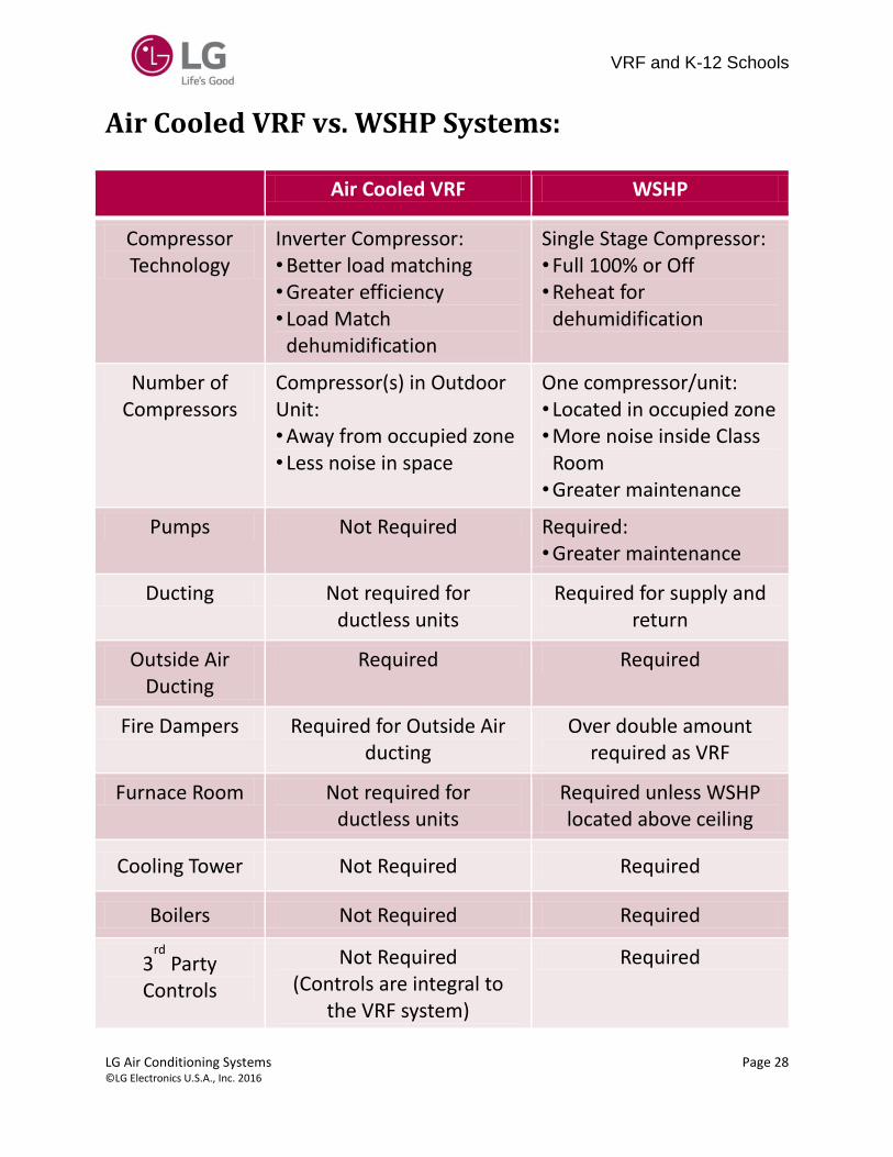
Air Cooled VRF vs. WSHP Systems:
Air Cooled VRF WSHP
Compressor Technology
Inverter Compressor: • Better load matching
• Greater efficiency
• Load Match dehumidification
Single Stage Compressor: • Full 100% or Off • Reheat for
dehumidification
Number of Compressors
Compressor(s) in Outdoor Unit: • Away from occupied zone
• Less noise in space
One compressor/unit: • Located in occupied zone
• More noise inside Class Room
• Greater maintenance
Pumps Not Required Required: • Greater maintenance
Ducting Not required for ductless units
Required for supply and return
Outside Air Ducting
Required Required
Fire Dampers Required for Outside Air ducting
Over double amount required as VRF
Furnace Room Not required for ductless units
Required unless WSHP located above ceiling
Cooling Tower Not Required Required
Boilers Not Required Required
3rd
Party Controls
Not Required (Controls are integral to
the VRF system)
Required

VRF and K-12 Schools
LG Air Conditioning Systems Page 29 © LG Electronics U.S.A., Inc. 2016
Air Cooled VRF WSHP
Make-Up Water Not Required for Air Source
System Required for WSHP
Water Treatment
Not Required on Air Source System
Required for WSHP
Air Balancing Easily done through Fan
Speed Control Required
Water Balancing Not Required Can be complicated and
costly
Continued Adjustment and
Balancing Not Required
May take a couple weather seasons (Each
building is different)
System Operation and Maintenance
Easy to operate and maintain
Requires training: • How to operate system
of pumps, WSHPs, cooling tower, boiler/s
• Extensive Maintenance
VRF and K-12 Schools
LG Air Conditioning Systems Page 30 © LG Electronics U.S.A., Inc. 2016
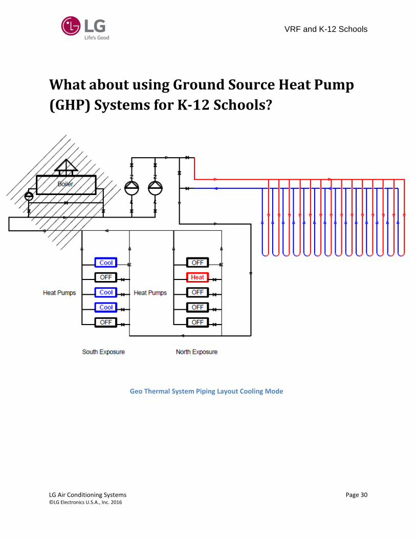
What about using Ground Source Heat Pump
(GHP) Systems for K-12 Schools?
Geo Thermal Loop in Ground Cooling
Mode
Boiler May or May Not Be Used
Geo Thermal System Piping Layout Cooling Mode
VRF and K-12 Schools
LG Air Conditioning Systems Page 31 © LG Electronics U.S.A., Inc. 2016
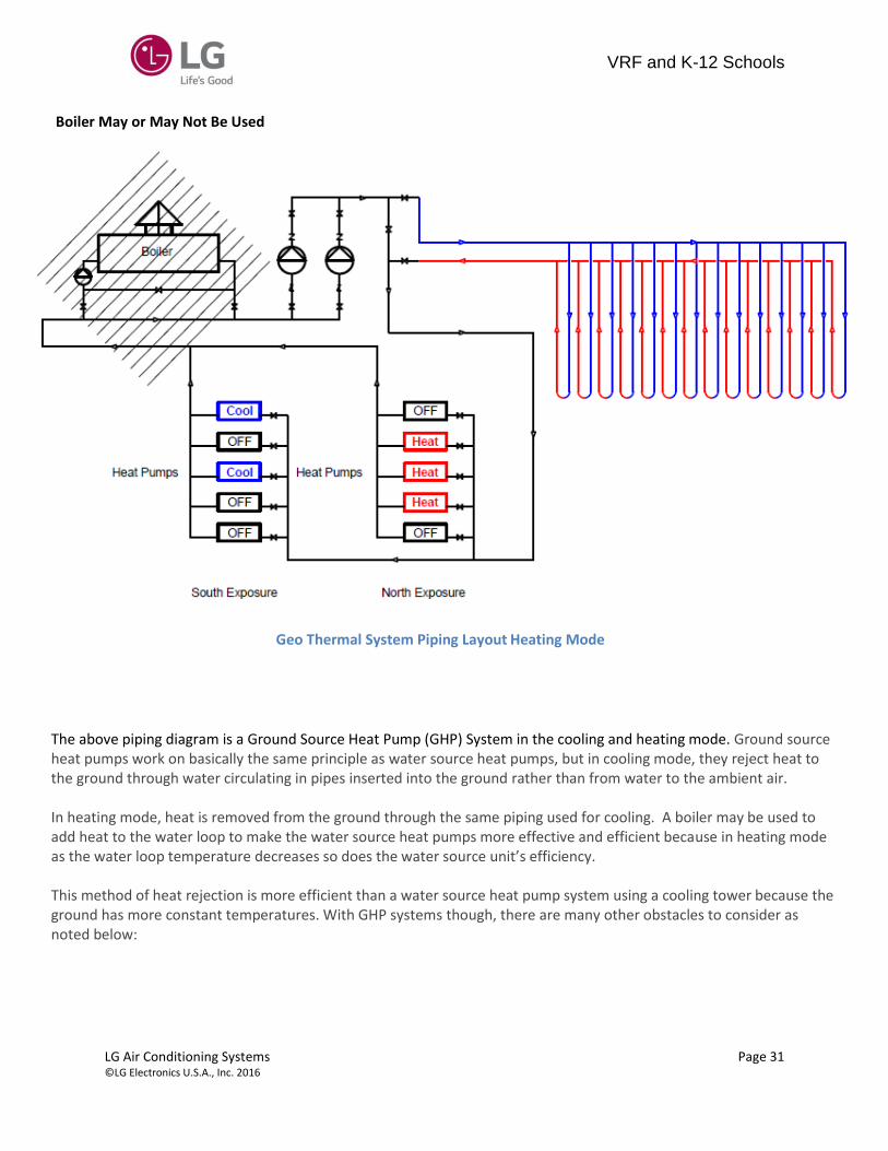
Boiler May or May Not Be Used
Geo Thermal System Piping Layout Heating Mode
The above piping diagram is a Ground Source Heat Pump (GHP) System in the cooling and heating mode. Ground source heat pumps work on basically the same principle as water source heat pumps, but in cooling mode, they reject heat to the ground through water circulating in pipes inserted into the ground rather than from water to the ambient air. In heating mode, heat is removed from the ground through the same piping used for cooling. A boiler may be used to add heat to the water loop to make the water source heat pumps more effective and efficient because in heating mode as the water loop temperature decreases so does the water source unit’s efficiency. This method of heat rejection is more efficient than a water source heat pump system using a cooling tower because the ground has more constant temperatures. With GHP systems though, there are many other obstacles to consider as noted below:

VRF and K-12 Schools
LG Air Conditioning Systems Page 32 © LG Electronics U.S.A., Inc. 2016
The above map shows how the ground temperatures varying from one area to others. It is
interesting to note that the temperatures are not constant but rather are averages. Comfort
heating and cooling is not determined using average temperatures but worst case. So care
should be exercised when using the map to determine the ground temperatures that can be used
to calculate the heating and cooling load.
Ground
Temperatures
are Before
Adding Load
(Btu/hr)
Higher Ground Temp
= Less GHP Efficiency=
Bigger Ground Loop
=More $$
Mean annual earth temperature (Average Temperatures – Not Constant Temperatures)
observations at individual stations, superimposed on well-water temperature contours
11/26/2014 http://www.builditsolar.com/Projects/Cooling/EarthTemperatures.htm
Understanding Average Ground Temps

VRF and K-12 Schools
LG Air Conditioning Systems Page 33 © LG Electronics U.S.A., Inc. 2016
Ground Temps Vary (at different depths)
04/30/2015 http://igs.indiana.edu/Geothermal/HeatPumps.cfm
Deep Borehole Wells
are costly, but have the
most constant ground
temps
Understanding Average Ground Temps
The above graph shows how the ground temperatures varying in depth. The most constant temperatures
are those that have the greatest depth in the ground. For this reason, deep boreholes are the
recommended method of ground heat pump loop construction. Deep boreholes have to be drilled into the
ground and because of that they are also the most expensive.

VRF and K-12 Schools
LG Air Conditioning Systems Page 34 © LG Electronics U.S.A., Inc. 2016
Thermal Conductivity (K) of the ground used to determine the number of wells:
• Thermal Conductivity(K) • Btu/hr = K (Area) Temp Difference / Thickness • Different Soil types at different depths
Soil Type affects Well Field $$ Cost
11/26/2014 http://www.builditsolar.com/Projects/Cooling/EarthTemperatures.htm
Smaller K = Less Heat Transfer= More Wells = $$
There are different soil types at different levels in the ground and each different soil type has different
Thermal Conductivity (K) values. The K value determines how many wells are needed to reject and absorb
heat for a given load.

VRF and K-12 Schools
LG Air Conditioning Systems Page 35 © LG Electronics U.S.A., Inc. 2016
Well Type: Closed Loop Grout Sealed Well
Confined Aquifer
Upper Confining
Bed
Lower Confining Bed
Topsoil
Borehole Wall Un-grouted
Borehole
Trench
HDPE
Pipe
HDPE
Pipe
Static Water Level
HDPE U Bend
Local Governments are restricting use
of open wells because of potential to
contaminate ground water
The above is an example of a closed loop grout sealed well. A well of 200 – 800’ deep is drilled and HDPE pipe
is routed down into the well. The HDPE piping is connected to other wells to make network of wells that are
used to reject and absorb heat for a GHP system.

VRF and K-12 Schools
LG Air Conditioning Systems Page 36 © LG Electronics U.S.A., Inc. 2016
Mean annual earth temperature (Average Temperatures not Constant
Temperatures) observations at individual stations, superimposed on well-water
• Test Bore Hole drilled • Known amount of heated water pumped • through the loop
• Temperature Difference (Tsupply
–Treturn
) is
measured • Result is used to calculate K value • Estimated Cost of $ 7,500/each Test Borehole
Known Heat Rate Btu/hr
Ho
t °F Sup
ply W
ater
Co
ol °
F Su
pp
ly W
ate
r
Known Flow Rate GPM
How is Ground K Properly Determined?
The above is a diagram of how the ground K value is determined. A known amount of water at a known
temperature is pumped down through the pipe in the well and the returning water temperature is used to
determine the K value.

VRF and K-12 Schools
LG Air Conditioning Systems Page 37 © LG Electronics U.S.A., Inc. 2016
Beware of Marketed EER
• GHP Published cooling 27 EER is based on 50°F loop water temperature: • AHRI 330 Rating Conditions for GLHP Cooling @80°F dry bulb/67°F
wet bulb, 77°F Entering water • Cooling @80°F dry bulb/67°F wet bulb, 77°F Entering water = 17.1 *
EER, not 27!! • Does not include pump and other losses!!
• AHRI 330 Rating Conditions for GLHP Heating @70°F dry bulb/60°F wet bulb, 32°F Entering water = 4.0 COP
* 11/26/2014 https://www.climatemaster.com/share/ResAllProductsCLM/Section3TT27.pdf
http://www.ahrinet.org/App_Content/ahri/files/standards%20pdfs/AHRI%20standards%20pdfs/AHRI%20Sta
ndard%20330-1998.pdf
Smaller EER = Less Efficient = More Operation $$

VRF and K-12 Schools
LG Air Conditioning Systems Page 38 © LG Electronics U.S.A., Inc. 2016
Beware of Marketed EER
Pump Power Consumption not included in AHRI ratings:
Assumptions:
• 40 GPM @ 50’ Head Pressure, 30% Glycol Fluid • Pump HP = 3 (Pump HP from Taco 7.0 Pump Selection Program) • Pump Full Load Amps (FLA) @ 3 HP /460/3/60 = 4.8 Amps • Pump Power Factor = 0.84 • Pump Power(Watts) = (Volts X Amperage X √3) X 0.84 • Pump Power(Watts) = 3,824 Watts X 0.84 = 3,212 Watts • GHP Power(Watts) = 20,877 Watts • System EER = Btu/hr/Watts (GHP + Pump) • System EER with Pump Power Consumption = 14.8 Cooling System EER!!

VRF and K-12 Schools
LG Air Conditioning Systems Page 39 © LG Electronics U.S.A., Inc. 2016
Air Cooled VRF vs. GHP Systems:
Air Cooled VRF GHP
Compressor Technology
Inverter Compressor: • Better load matching
• Greater efficiency
• Load Match dehumidification
2 Stage Compressor: • Full 100% or partial 67%
• 2 Speeds – High or Low
• Reheat for dehumidification
Number of Compressors
Compressor(s) in Outdoor Unit: • Away from occupied zone
• Less noise in space
One compressor/unit: • Located in occupied zone
• More noise inside space
• Greater maintenance
Furnace Room Not required for ductless units
Required unless WSHP/GHP
located above ceiling
Ground Loop Not Required Required
Cooling Tower Not Required • Required when ground loop is too warm
• Required for Hybrid system
Boilers Not Required • Required when ground loop doesn't have enough heat
• Required for Hybrid system
3rd
Party Controls
Not Required (Controls are integral to
the VRF system)
Required

VRF and K-12 Schools
LG Air Conditioning Systems Page 40 © LG Electronics U.S.A., Inc. 2016
Air Cooled VRF vs. GHP Systems:
Air Cooled VRF GHP
Make-Up Water Not Required for Air Source
System Required for GHP and
Hybrid System
Water Treatment
Not Required on Air Source System
Required for GHP and Hybrid System
Air Balancing Easily done through Fan
Speed Control Required
Water Balancing Not Required Can be complicated and
costly
Continued Adjustment and
Balancing Not Required
May take a couple weather seasons (Each
building is different)
System Operation and Maintenance
Easy to operate and maintain
Requires training: • How to operate system
of pumps, GHPs, cooling tower, boiler/s
• Extensive Maintenance

VRF and K-12 Schools
LG Air Conditioning Systems Page 41 © LG Electronics U.S.A., Inc. 2016
Use LG Multi V Water IV Instead of WSHP/GHP LG Multi V Water IV water source systems offer the opportunity to minimize ductwork in the same configuration. The system offers zoning without the need for zone damper systems. The LG Multi V Water IV system’s advanced controls provide exceptional building dehumidification and temperature control, and can rapidly adapt system operating parameters to an ever-changing building load. The LG Multi V Water IV system is easy to design, install, and maintain. The modular design allows occupants to control their environmental condition, providing individualized control of the set-point temperature and allowing occupants to condition only the occupied zones.
Multi V Water IV, a Variable Refrigerant Flow (VRF) system, is among the industry’s best air-conditioning
units with great advantage on vertical rise and piping lengths. Choosing an LG Multi V Water IV VRF
system provides the system designer an edge to engineer a system with individual control and design
flexibility with advanced controls. Multi V Water IV is available in two configurations, heat pump and
heat recovery.
Multi V Water IV heat pumps are two-pipe systems available in nominal capacities of 6.0 to 48.0 tons.
These are best suited for applications with zones that require heating or cooling, such as residential and
small office buildings.
Multi V Water IV heat recovery is a three pipe system that provides simultaneous heating and cooling
operation from the same water source unit. Both Multi V Water IV heat pump and heat recovery
systems allow the designer to accommodate up to 64 thermal zones, each controlled from a separate
controller.
Multi V Water IV water source units are available in 208–230 Volt, 60 Hz, 3 Phase and 460 Volt, 60 Hz, 3
Phase.

VRF and K-12 Schools
LG Air Conditioning Systems Page 42 © LG Electronics U.S.A., Inc. 2016
Adaptable and Flexible
Multi V Water IV water source units can be adapted to a wide range of building applications and sizes such as schools. The lightweight and small footprint allows system components to be placed in the building without expensive cranes, easily fitting into most service elevators and set in place with minimal requirements for structural reinforcements. The modular design of VRF systems means Multi V Water IV can be commissioned in stages so tenants can move in as each floor or even each room is completed. Multi V Water IV technology allows you to pipe farther, reaching all areas of a building that would require the installation of a second system when using traditional direct-expansion cooling and heating equipment. Multi V Water IV provides the designer with uncompromised pipe system engineering flexibility—long pipe runs and large elevation differences.
Pump Beware
Classrooms
Multi V IV Heat Recovery
Water Application with
Geo Exchange Loop
Classrooms
Boiler
Boiler
Wat
er P
ipe
Ref
rige
ran
t P
ipe
Multi V IV Heat Recovery
Water Application with
Cooling Tower & Geo Exchange Loop
Multi V IV Heat Recovery
Water Application with
Geo Exchange Loop
Ref
rige
ran
t P
ipe
Multi V IV Heat Recovery
Water Application with
Cooling Tower
Closed Circuit
Cooling Tower
Classrooms
Wat
er P
ipe
Ref
rige
ran
t P
ipe
Boiler
Multi V IV Heat Recovery
Water Application with
Cooling Tower

VRF and K-12 Schools
LG Air Conditioning Systems Page 43 © LG Electronics U.S.A., Inc. 2016
Closed Circuit
Cooling Tower
Wat
er P
ipe
Ref
rige
ran
t P
ipe
Boiler
Multi V IV Heat Recovery
Water Application with Mini Multi V
Server Room
Ref
rige
ran
t P
ipe
Multi V IV Heat Recovery
Water Application with Ducted IDU Closed Circuit
Cooling Tower
Boiler
Multi V IV Heat Pump
Water Application with Separate Thermal Zones

VRF and K-12 Schools
LG Air Conditioning Systems Page 44 © LG Electronics U.S.A., Inc. 2016
Condenser Water Supply
Condenser Water Return
Shutoff Valve
Thermometer
Shutoff Valve
Thermometer
Pressure Gauge Pressure Gauge
Service Valve
Shutoff
Valve
50 Mesh
Strainer PWFCKN000
Flex
Connector
Modulating Control
Valve
Valve Power (24V)
and Control
Flow
Switch
Service Valve
Variable Water Flow Valve Control Kit For variable speed applications, LG has and recommends the below control kit:
Variable Water Flow Valve Control Kit PWFCKN000 • When entering water temperature is lower than 59°F, variable water flow control kit PWFCKN000 is required
• LG recommends installing a variable water flow control kit on each water source unit
• Field supplied 24 volt modulating control valve
• Minimum flow rate ≥ 40% normal flow rate
• 0-10 Volt Signal

VRF and K-12 Schools
LG Air Conditioning Systems Page 45 © LG Electronics U.S.A., Inc. 2016
99°F
Bypass
Valve Temperature
Sensor
Control Wiring
90°F
Pumping Operation
Signal
Room 1 Room 2 Room 3
To other Water Source Units
Ref
rige
ran
t P
ipe
Co
nd
ense
r W
ater
pip
e
Control
Wiring
Water Cooled VRF (Cooling Mode Operation)

VRF and K-12 Schools
LG Air Conditioning Systems Page 46 © LG Electronics U.S.A., Inc. 2016
To Other Water
Source Units
Mechanical Room
Room 1 Room 2 Room 3
Co
nd
ense
r W
ater
pip
e
Ref
rige
ran
t P
ipe
68°F
59°F
Bypass
Valve
Temperature
Sensor
Water Cooled VRF (Heating Mode Operation)

VRF and K-12 Schools
LG Air Conditioning Systems Page 47 © LG Electronics U.S.A., Inc. 2016
Water Cooled VRF (Piping Connections)
Temperature
Gauge
Water Drain Pipe
Flex Connector (2)
Gate Valve
Gate Valve
Pressure
Gauge
Strainer
(50
Mesh)
Gate Valve
Water Balancing Valve
High Pressure Vapor
Low Pressure Vapor (HR units only)
Liquid
PT Service Port
(for HEX cleaning)

VRF and K-12 Schools
LG Air Conditioning Systems Page 48 © LG Electronics U.S.A., Inc. 2016
Water Cooled VRF vs. WSHP/GHP Systems:
Water Cooled VRF WSHP/GHP
Compressor Technology
Inverter Compressor: • Better load matching
• Greater efficiency
• Load Match dehumidification
2 Stage Compressor: • Full 100% or partial 67%
• 2 Speeds – High or Low
• Reheat for dehumidification
Number of Compressors
Compressor(s) in Outdoor Unit: • Away from occupied zone
• Less noise in space
One compressor/unit: • Located in occupied zone
• More noise inside space
• Greater maintenance
Electrical Less Electrical Load - Lower electrical power wiring and
switchgear costs
Greater Electrical Load - Greater electrical power
wiring and switchgear costs
Water Piping Less required More required than VRF
Pumping Less GPM – less pump
power required More GPM than VRF
Maintenance Easier due to centrally
located condensing units
Greater than VRF due to being located through-
out the school instead of a central location
3rd
Party Controls
Not Required (Controls are integral to
the VRF system)
Required

VRF and K-12 Schools
LG Air Conditioning Systems Page 49 © LG Electronics U.S.A., Inc. 2016
LG Hydro Kit The LG Hydro Kit is an efficient way to recover waste heat from VRF air conditioning systems. The Hydro Kit receives heat from the Multi V VRF systems’ waste heat to provide hot water for use where it is needed in areas such as kitchens, bathrooms, radiators, and floor heating. The LG Hydro kit provides hot water with less energy consumption than a boiler. Gas Boiler systems require exhaust to the outside. No exhaust or exhaust piping is required with the Hydro Kit. The LG Hydro Kit is compact and easy to install, and can connect to multiple heat pumps in a system for additional savings. The Hydro Kit may be used in conjunction with 3-phase Multi V Heat Pump and Heat Recovery outdoor and water source units. The Hydro Kit system uses a refrigerant to water heat exchanger to produce chilled or heated water. Hydro Kit can be used to preheat domestic water stored in an indirect storage tank, snow melt, in-floor or other radiant heating systems. Alternately, the K2 Hydro kit can supply chilled or heated water for use with 2-pipe fan coils and the K3 Hydro kit can produce hot water up to 176°F.
Hot water out: MAX 122°F MAX 176°F
Cold water out: 43°F
Cooling Capacity: 96 MBh
Heating Capacity: 108 MBh 86 MBh
ARNH963K2A2 ARNH763K3B2
K2
K3

VRF and K-12 Schools
LG Air Conditioning Systems Page 50 © LG Electronics U.S.A., Inc. 2016
Hydro Kit Applications (Air and Water Cooled)
HR Unit
Hot-water tank
Heating
Medium Temp.
Hydro kit
High Temp.
Hydro kit
Refrigerant
cooling/heating
Multi V
Heat Recovery
R
Water
cooling/heating
Water
cooling/heating
Medium temp Hydro Kit
Heat exchanger
High temp Hydro kit
Indoor unit
HR Unit
Waste heat
Multi V WATER
Rejected heat
from IDU
Rejected heat
from IDU
Cooling Tower
Indoor unit

VRF and K-12 Schools
LG Air Conditioning Systems Page 51 © LG Electronics U.S.A., Inc. 2016
Hydro Kit Domestic Hot Water

VRF and K-12 Schools
LG Air Conditioning Systems Page 52 © LG Electronics U.S.A., Inc. 2016
What about the use of Air Cooled Chilled
Water Systems for K-12 Schools?

VRF and K-12 Schools
LG Air Conditioning Systems Page 53 © LG Electronics U.S.A., Inc. 2016
Air-Cooled Chillers for K-12 HVAC Air cooled chillers reject heat to the atmosphere by blowing air over a fin-tube heat exchanger through
which flows the refrigerant. Air condensers are less expensive and easier to maintain than the cooling
towers required by water-cooled chillers. However, the evaporative effect of cooling towers enables
water cooled chillers to operate at lower condenser temperatures and pressures, which increases chiller
efficiency. Thus, air-cooled chillers are recommended for applications in which low first cost and
maintenance costs outweighs the reduced efficiency compared to water cooled chillers.
LG VRF offers the benefit of lower first cost and maintenance, and high efficiency as compared to air and
water cooled chillers. With LG VRF, operation is very simple, as simple as operating a split air
conditioning system and hence no separate manpower is required for operating the system.
LG VRF is a better option for providing air conditioning to K-12 schools where the complexity of the
system can be kept to a minimum and energy efficiency is maximized.
The energy efficiency of air-cooled chillers is rated in terms of Energy Efficiency Ratio (EER). EER is a
dimensional measure of efficiency. It is the ratio of the rate of cooling to electrical power consumption
by the evaporator and the condenser fans.
EER (Btu/Wh) = Qevap (Btu/hr.) / (Wcomp + W condfans) (W) @ ARI Std 590-92 conditions
The performance of a typical air cooled chiller is shown below. As predicted by a Carnot analysis,
efficiency improves when the temperature of air entering the condenser declines or the leaving water
temperature increases.
Air-Cooled Chiller Evaporator and Condenser Temperature Performance Map
(Does not include Pump or Other Losses)
Using the data in the preceding table, the following relation gives chiller EER as a function of leaving
water temperature of 45 °F and when the condenser air temperature is 95 F. The resultant EER is 9.7.
This EER value does not include pump losses. The additional pump losses are calculated as below using
TACO pump Selection Software:
LWT
°F Tons KW EER Tons KW EER Tons KW EER
20 28 11.4 15.7 8.7 10.2 19.2 6.4 8.8 23.8 4.4
25 24 12.9 16.1 9.6 11.5 19.7 7.0 10.0 24.4 4.9
30 19 14.5 16.6 10.5 13.0 20.2 7.7 11.3 24.9 5.4
35 14 16.1 17.0 11.4 14.5 20.7 8.4 12.6 25.5 5.9
40 0 17.9 17.5 12.3 16.1 21.2 9.1 14.1 26.1 6.5
45 0 19.5 17.9 13.1 17.6 21.7 9.7 15.5 26.7 7.0
50 0 21.3 18.4 13.9 19.2 22.3 10.3 16.9 27.2 7.5
55 0 23.1 18.9 14.7 20.8 22.8 11.0 18.4 27.9 7.9
60 0 24.9 19.4 15.4 22.5 23.4 11.6 19.9 28.5 8.4
Percent
Glycol
Capacity System Capacity System Capacity System
Entering Condenser Air Temperature (°F)
75.0 95.0 115.0

VRF and K-12 Schools
LG Air Conditioning Systems Page 54 © LG Electronics U.S.A., Inc. 2016
Operating Cost Estimate Examples:
80 Ton VRF: Cooling
Given:
• 28,000 Ft² School, 80 Tons Cooling Load, 27 classrooms, 3 tons load per classroom
• Outside Ventilation Air handled separately
• Gym HVAC on separate system
• 2 X (ARNU183TQC2 – 4 way Cassette) Indoor units per 27 classrooms = 54 Total
• 4 X (ARUB264 – 22 Ton Outdoor Unit) = 80 tons @ 75:F DB / 63:F WB
• 1,500 VRF Cooling Run Hours per year (Reduced Cooling Run Hours due to VRF compressor)
• $/KWh = $ 0.10 Blended (Consumption and Demand) Rate
• VRF Outdoor Unit Power Input KW from LG Performance Data for Multi V IV @ 75 db/63 wb Indoor Temperature, 95 db Outdoor Temperature (4 x 22 Ton @ 100% Combination Ratio) = (4 X 14.3) = 57.16 KW for Outdoor Unit
• VRF Indoor Unit Power Input KW from LG Performance Data for (Total 54) – (2 per 27 classrooms) ARNU183TQC2 Ceiling Cassette @ 80 db/67 wb Indoor Temperature, 95 db Outdoor Temperature (54 x 30 watts) = 1.62KW for Total Indoor Units
Solution:
• Total Power Input (Watts) for VRF = (57,160 Outdoor Unit + 1,620 Indoor Unit) = 58,780 Total Watts
• 80 Tons = 80 X 12,000 Btu/hr. / Ton = 960,000 Btu/hr.
• System EER = Btu/hr. / Power Input (Watts) = 960,000/58,780 = 16.0 EER
• Annual Energy Cost (Cooling)= Annual Run Hours X KW X $/KWh
• Annual Energy Cost (Cooling) = 1,500 X 58.8 X 0.10 = $ 8,820 Annual Cost of Cooling (VRF)

VRF and K-12 Schools
LG Air Conditioning Systems Page 55 © LG Electronics U.S.A., Inc. 2016
80 Ton VRF: Heating
Given:
• 2 X (ARNU183TQC2 – 4 way Cassette) Indoor units per 27 classrooms = 54 Total
• 4 X (ARUB264 – 22 Ton Outdoor Unit) = 4 X (275.9 Mbh Heating) = 1,103.6 Mbh Heating
• Power(kW) = P(BTU/hr) / 3,412 = 1,103,600 Btu/hr. / 3,412 = 323 kW
• 600 VRF Heating Run Hours per year (Reduced Heating Run Hours due to VRF compressor)
• $/KWh = $ 0.10 Blended (Consumption and Demand) Rate
• VRF Outdoor Unit Power Input KW from LG Performance Data for Multi V IV @ 70:F db Indoor Temperature, 10:F db Outdoor Temperature (4 x 22 Ton @ 100% Combination Ratio) = (4 X 26.94) = 107.8 KW for Outdoor Unit (Heating)
• VRF Indoor Unit Power Input KW from LG Performance Data for (Total 54) – (2 per 27 classrooms) ARNU183TQC2 Ceiling Cassette @ 70:F db Indoor Temperature, 10:F db Outdoor Temperature (54 x 30 watts) = 1.62KW for Total Indoor Units
Solution:
• Total Power Input (Watts) for VRF = (107,760 + 1,620) = 109,380 Total Watts
• System COP = Power Out (Watts) / Power Input (Watts)
• System COP = 323,000/109,380 = 2.95 COP (Heating @ 10⁰F Outdoor Temperature)
• Annual Energy Cost (Heating)= Annual Run Hours X KW X $/KWh
• Annual Energy Cost (Heating)= 600 X 109.4 X $ 0.10 = $ 6,564 Annual Cost of Heating (VRF)

VRF and K-12 Schools
LG Air Conditioning Systems Page 56 © LG Electronics U.S.A., Inc. 2016
Roof Top Unit (RTU) versus VRF: Cooling
Given:
• (27) 3 Ton (RTUs) 1 for each classroom
• 2000 (RTU) Annual Full Load Run Hours
• 11.2 EER/13 SEER from performance data
• 3 Ton = 36,000 Btu/hr.
• Power Input (Watts) = 36,000 Btu/hr. / 11.2 EER = 3,214 (Watts)
• 3,214 (Watts) = 3.214 kW
• (27) X 3.214 kW = 86.78 kW
Solution:
• Annual Energy Cost (Cooling)= Annual Run Hours X KW X $/KWh
• Annual Energy Cost (Cooling) = 2000 Hours X 86.78 KW X 0.10 = $ 17,356
$ 17,356 - $ 8,820 = $ 8,536 Annual Savings with VRF (Cooling)

VRF and K-12 Schools
LG Air Conditioning Systems Page 57 © LG Electronics U.S.A., Inc. 2016
Roof Top Unit (RTU) versus VRF: Heating
Given:
• 600 Annual Full Load Run Hours, RTUs in Heating
• $/Therm = $ 0.55/Therm, Therm = 100,000 Btus/hr.
• 120,000 Btus/hr. Heating Input from performance data
• 120,000 Btus/hr. / 100,000 Btus/hr. = 1.2 Therms
• (27) Roof Top Units (RTU) – One per each classroom, (27) X 1.2 Therms = 32.4 Therms
• 3 Ton RTU Evaporator Fan, ¾ H.P. Per performance data
• RTU Amps (FLA) @ ¾ HP /460/3/60 = 1.4 Amps X 27 = 37.8 Amps
• Power Factor = 0.84
• Fan Power(Watts) = (Volts X Amperage X √3) X 0.84
• Fan Power(Watts) = (460 X 37.8 X √3) X 0.84 = 25,298 Total Watts
• 25,298 Watts / 1000 Watts/kW = 25.3 kW
Solution:
• Annual Energy Cost (Electric)= Run Hours X kW X $/kWh = 600 X (25.3) X $0.10 = $1,518
• Annual Energy Cost (Natural Gas) = 600 Hours X 32.4 Therms X 0.55= $10,692
• Total Annual Cost = ($1,518 + $10,692) = $12,210
$ 12,210 - $ 6,564 = $ 5,646 Annual Savings with VRF (Heating)

VRF and K-12 Schools
LG Air Conditioning Systems Page 58 © LG Electronics U.S.A., Inc. 2016
Air Cooled Chiller/Fan Coil Units (FCU) versus VRF: Cooling
Given:
• 80 Ton Chiller, 160 GPM @ 50’ Head Pressure, 30% Glycol Fluid
• 2000 Chiller/Fan Coil Unit Annual Full Load Run Hours
• 82.3 KW Power Input for Chiller from performance data
• (27) Fan Coil Units (FCU) – One per each classroom, ½ H.P. Per each from performance data
• FCU Amps (FLA) @ 1/2 HP 277/1/60 = 3.3 Amps X 27 = 89.1 Amps
• Power Factor = 0.84
• FCU (Watts) = (Volts X Amperage) X 0.84
• FCU (Watts) = (277 X 89.1) X 0.84 = 20,732 Total Watts
• Pump HP = 5 (Pump HP from Taco 7.0 Pump Selection Program)
• Pump Full Load Amps (FLA) @ 5 HP /460/3/60 = 7.6 Amps
• Pump Power(Watts) = (Volts X Amperage X √3) X 0.84
• Pump Power(Watts) = 6,055 Watts X 0.84 = 5,086 Watts
• 80 Ton Chiller Power(Watts) = 82,300 Watts
• System EER = Btu/hr./Watts (Chiller + Pump + Fan Coil Units)
• System EER = 960,000/(82,300 + 5,086 + 20,732)=8.8 EER
Solution:
• Total Power Input (Watts) for Chiller/FCUs = (82,300 + 5,086 + 20,732) = 108,118 Watts = 108.1 KW
• 80 Tons = 80 X 12,000 Btu/hr. / Ton = 960,000 Btu/hr.
• Annual Energy Cost (Cooling)= Annual Run Hours X KW X $/KWh
• Annual Energy Cost (Cooling) = 2000 Hours X 108.1 KW X 0.10 = $ 21,620
$ 21,620 - $ 8,820 = $ 12,800 Annual Savings with VRF (Cooling)

VRF and K-12 Schools
LG Air Conditioning Systems Page 59 © LG Electronics U.S.A., Inc. 2016
Air Cooled Chiller/Fan Coil Units (FCU) versus VRF: Heating
Given:
• 800 Annual Full Load Run Hours, FCUs in Heating
• $/Therm = $ 0.55/Therm, Therm = 100,000 Btus/hr.
• 1,388,235 Btus/hr. Boiler Power Input from performance data
• 1,388,235 Btus/hr. / 100,000 Btus/hr. = 13.88 Therms
• (27) Fan Coil Units (FCU) – One per each classroom, ½ H.P. Fan Per each from performance data
• FCU Amps (FLA) @ ½ HP 277/1/60 = 3.3 Amps X 27 = 89.1 Amps
• Power Factor = 0.84
• Fan Power(Watts) = (Volts X Amperage) X 0.84
• Fan Power(Watts) = (277 X 89.1) X 0.84 = 20,732 Total Watts
• Pump(System) HP = 2 (Pump HP from Taco 7.0 Pump Selection Program)
• Pump(Boiler) HP = 3/4(From Boiler Performance Data)
• Pump(System) Full Load Amps (FLA) @ 2 HP /460/3/60 = 3.4 Amps
• Pump(System) Power(Watts) = (Volts X Amperage X √3) X 0.84
• Pump(System) Power(Watts) = 2,709 Watts X 0.84 = 2,276 Watts
• Pump(Boiler) (FLA) @ ¾ HP /460/3/60 = 1.4 Amps
• Pump(Boiler) Power(Watts) = (Volts X Amperage X √3) X 0.84 = (460 X 1.4 X √3) X 0.84 = 937 Watts
• Total Power input (Watts) = (FCUs + Pump(System) + Pump(Boiler))
• Total Power input (Watts) = (20,732 + 2,276 + 937) = 23,945 Watts = 23.9 KW
Solution:
• Annual Energy Cost (Electric)= Run Hours X KW X $/KWh = 800 X (23.9) X $0.10 = $1,912
• Annual Energy Cost (Natural Gas) = 800 Hours X 13.88 Therms X 0.55= $6,107
• Total Annual Cost = ($1,912 + $6,107) = $8,019
$ 8,019 - $ 6,564= $ 1,455 Annual Savings with VRF (Heating)

VRF and K-12 Schools
LG Air Conditioning Systems Page 60 © LG Electronics U.S.A., Inc. 2016
Water Source Heat Pump (WSHP) with Cooling Tower/Boiler versus
VRF: Cooling
Given:
• (27) WSHPs @ 3 Ton/Each, 8.4 GPM/Each, 227 GPM Total @ 50’ Head Pressure, 30% Glycol Fluid
• 2000 WSHP Unit Annual Full Load Run Hours
• Pump(System) HP = 5 (Pump HP from Taco 7.0 Pump Selection Program)
• Pump(System) Full Load Amps (FLA) @ 5 HP /460/3/60 = 7.6 Amps
• Power Factor = 0.84
• Pump(System) Power(Watts) = (Volts X Amperage X √3) X 0.84
• Pump(System) Power(Watts) = 6,055 Watts X 0.84 = 5,086 Watts
• (27) WSHPs @ 1.899 KW/Each (from performance data), Total 51.3 (Kilowatts) WSHPs
• Cooling Tower has (1) 10 HP Fan Motor and (1) 2 HP Pump Motor
• Cooling Tower Fan 10 HP @ /460/3/60, (FLA) = 14.0 Amps,
• Cooling Tower Pump(Cooling Tower) 2 HP @ /460/3/60, (FLA) = 3.4 Amps
• Total Cooling Tower (FLA) = (14.0 + 3.4) = 17.4 Amps
• Cooling Tower Power(Watts) = (Volts X Amperage X √3) X 0.84
• Cooling Tower Power(Watts) = 13,863 watts X 0.84 = 11,645 Watts
• System Total (Watts) (WSHPs + Pump(System) + Cooling Tower) = (51,300 + 5,086 + 11,645) = 68,031 Watts
Solution:
• System EER = Btu/hr./Watts (WSHPs + Pump(System) + Cooling Tower)
• System EER = (960,000 Btu/hr./68,031 Watts) = 14.1 EER
• 68 KW X 2000 run hours = 136,000 KWh x $ 0.10 = $ 13,600 (Annual Cooling cost with WSHP)
$ 13,600 - $ 8,820 = $ 4,780 Annual Savings with VRF (Cooling)

VRF and K-12 Schools
LG Air Conditioning Systems Page 61 © LG Electronics U.S.A., Inc. 2016
Water Source Heat Pump (WSHP) with Cooling Tower/Boiler versus VRF: Heating
Given:
• (27) WSHPs @ 41 Mbh/Each, 8.4 GPM/Each, 227 GPM Total @ 50’ Head Pressure, 30% Glycol Fluid
• Power Input (WSHPs) = 2.38 kW/ Each X 27 = 64.26 kW
• Total Mbh Boiler Load = 70% of (27 X 41Mbh) = 775 Mbh Total Boiler Load
• High Efficiency Natural Gas Boiler used for heating loop water = 89% Efficient
• Use 1000 MBH Boiler with Net Capacity = 1,000 MBH X .89 = 890 MBH
• 800 WSHP Unit Annual Heating Full Load Run Hours/400 Run Hours for the Boiler
• Pump(System) HP = 7.5 (Pump HP from Taco 7.0 Pump Selection Program)
• Pump(System) Full Load Amps (FLA) @ 7.5 HP /460/3/60 = 11.0 Amps
• Power Factor = 0.84
• Pump(System) Power(Watts) = (Volts X Amperage X √3) X 0.84
• Pump(System) Power(Watts) = 8,764 Watts X 0.84 = 7,362 Watts
• Pump(Boiler) (FLA) @ ¾ HP (from performance data) /460/3/60 = 1.4 Amps
• Pump(Boiler) Power(Watts) = (Volts X Amperage X √3) X 0.84 = (460 X 1.4 X √3) X 0.84 = 937 Watts
• Boiler has 1,000,000 Btus/h / 100,000 Btus/h = 10.0 Therms Input
• Total (Watts) (WSHPs + Pump(System) + Pump(Boiler)) = (64,260 + 7,362 + 937) = 72,559 Watts
Solution:
• Annual Energy Cost (Electric)= Run Hours X KW X $/KWh = 800 X (72.6) X $0.10 = $5,808
• Annual Energy Cost (Natural Gas) = 400 Hours X 10.0 Therms X 0.55= $2,200
• Total Annual Cost = ($5,808 + $2,200) = $8,008
$ 8,008 - $ 6,564 = $ 1,444 Annual Savings with VRF (Heating)

VRF and K-12 Schools
LG Air Conditioning Systems Page 62 © LG Electronics U.S.A., Inc. 2016
Geo-Thermal Heat Pump (GHP) versus VRF: Cooling
Given:
• (29) GHPs needed to match VRF Performance @ 34.5 Mbh/Each, 960 Mbh Total, 8.4 GPM/Each, 244 GPM Total @ 50’ Head Pressure, 30% Glycol Fluid
• 2000 GHP Unit Annual Full Load Run Hours
• Pump(System) HP = 5 (Pump HP from Taco 7.0 Pump Selection Program)
• Pump(System) Full Load Amps (FLA) @ 5 HP /460/3/60 = 7.6 Amps
• Power Factor = 0.84
• Pump(System) Power(Watts) = (Volts X Amperage X √3) X 0.84
• Pump(System) Power(Watts) = 6,055 Watts X 0.84 = 5,086 Watts
• (29) GHPs @ 1.899 KW/Each, Total 55.1 (Kilowatts) GHPs
• Total (Watts) (GHPs + Pump(System)) = (55,100 + 5,086) = 60,186 Watts
Solution:
• System EER = Btu/hr./Watts (GHPs + Pump)
• System EER = (960,000 Btu/hr./60,186 Watts) = 15.9 EER
• 60.19 KW X 2000 run hours = 120,380 KWh x $ 0.10 = $ 12,038 (Annual Cooling cost with GHP)
$ 12,038 - $ 8,820 = $ 3,218 Annual Savings with VRF (Cooling)

VRF and K-12 Schools
LG Air Conditioning Systems Page 63 © LG Electronics U.S.A., Inc. 2016
Geo-Thermal Heat Pump (GHP) versus VRF: Heating
Given:
• 1,103.6 Mbh / 38.2 Mbh = 29 GHPs needed to match 1,103.6 Mbh from VRF
• (29) GHPs @ 38.2 Mbh/Each, 1,103.6 Mbh Total, 8.4 GPM/Each, 260.4 GPM Total @ 100’ Head Pressure, 30% Glycol Fluid, Performance based on 50:F Entering Water Temperature EWT
• Power In GHPs (kW) = 2.366 kW/Each X 29= 68.6 kW Total
• Power Out GHPs (kW) = P(BTU/hr) / 3,412 = 1,103,600 Btu/hr. / 3,412 = 299 kW
• 800 GHPs Unit Annual Full Load Run Hours
• Pump HP = 10 (Pump HP from Taco 7.0 Pump Selection Program)
• Pump Full Load Amps (FLA) @ 10 HP /460/3/60 = 14.0 Amps
• Power Factor = 0.84
• Pump Power(Watts) = (Volts X Amperage X √3) X 0.84
• Pump Power(Watts) = 11,154 Watts X 0.84 = 9,370 Watts
• Total (Watts) (GHPs + Pump) = (68,600 + 9,370) = 77,970Watts
Solution:
• System COP = Watts (Output)/Watts (WSHPs + Pump)
• System COP = (299,000 Watts/77,970 Watts) = 3.8 COP
• 78.0 KW X 800 run hours = 62,400 KWh x $ 0.10 = $ 6,616 (Annual Heating cost with GHP)
$ 6,616 - $ 6,564 = $ 52 Annual Savings with VRF (Heating)

VRF and K-12 Schools
LG Air Conditioning Systems Page 64 © LG Electronics U.S.A., Inc. 2016
System Type $Annual Energy Usage
$Cooling $Heating
VRF $8,820 $6,564
RTU $17,356 $12,210
Air Cooled Chiller/ Fan Coil Units (FCU)
$21,620 $8,019
Water Source Heat Pump (WSHP) with Cooling Tower/Boiler
$13,600 $8,008
Geo-Thermal Heat Pump (GHP) $12,038 $6,612

VRF and K-12 Schools
LG Air Conditioning Systems Page 65 © LG Electronics U.S.A., Inc. 2016
Thank You – For more information please contact your LG VRF Sales Person