vr-605 615 krf-v5060d v4060d v5560d - kenwood · audio video surround receivervr-605 vr-615...
TRANSCRIPT
AUDIO VIDEO SURROUND RECEIVER
VR-605VR-615KRF-V5060DKRF-V4060DKRF-V5560DINSTRUCTION MANUALKENWOOD CORPORATION
B60-5197-20 03 ID (K, P, T, M, Y, X, E2) 0109
This instruction manual is for some models. Model availability and features
(functions) may differ depending on the country and sales area.
About the supplied remote controlCompared to standard remote controls, the remote control supplied with this receiver has severaloperation modes. These modes enable the remote control to control other audio/video components. Inorder to effectively use the remote control it is important to read the operating instructions and obtain aproper understanding of the remote control and how to switch its operation modes (etc.).Using the remote control without completely understanding its design and how to switch the operationmodes may result in incorrect operations.
*5197/01-07/EN 26/03/2002, 2:48 PM1
2 EN
VIDEO 2COAXIAL
DVD
DIGITAL IN
CD / DVDOPTICAL
VOLTAGESELECTOR
AC110V-120V / 220V-240V~
50 / 60HzSWITCHED
TOTAL 90W MAX.
AC OUTLETS
AC 220-240V~
AC 110-120V~
SPEAKERS
SURROUNDSPEAKERS
(8-16Ω)
CENTER SPEAKER
(8-16Ω)
FRONTSPEAKERS
(8-16Ω)
GRAYWHITE GREEN BLUERED
L CR LR
CENTER
SUB WOOFERPRE OUT
SUBWOOFER SURROUNDFRONT
DVD / 6CH INPUT
PLAY INVIDEO 2
DVD
AUDIO
REC OUT PLAY INVIDEO1
PHONO REC OUT PLAY INMD / TAPE
CD / DVD
L
R
GND
VIDEO 1OUT
VIDEO 1IN
VIDEO
VIDEO 2IN
DVDIN
MONITOROUT
ANTENNA
GND
AMFM75Ω 75µs
AM 10kHzFM 100kHz
50µsAM 9kHzFM 50kHz
DE-EMPHASISCHANNELSPACE
SYSTEMCONTROL
+
-
+
-
As an ENERGY STAR® Partner, Kenwood
Corporation has determined that this
product meets the ENERGY STAR®
guidelines for energy efficiency.This
product can save energy. Saving energy
reduces air pollution and lowers utility bills.
Units are designed for operation as follows.
U.S.A. and Canada ........................................... AC 120 V only
Australia ........................................................... AC 240 V only
Europe and U.K. ............................................... AC 230 V only
China and Russia ............................................. AC 220 V only
Other countries .......... AC 110-120 / 220-240 V switchable*
Before applying the power Caution : Read this page carefully to ensure safeoperation.
Safety precautions
WARNING :
TO PREVENT FIRE OR ELECTRIC SHOCK,DO NOT EXPOSE THIS APPLIANCE TORAIN OR MOISTURE.
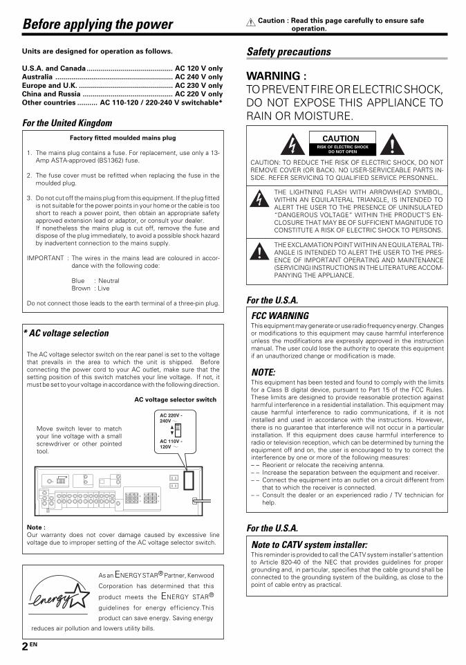
* AC voltage selection
The AC voltage selector switch on the rear panel is set to the voltagethat prevails in the area to which the unit is shipped. Beforeconnecting the power cord to your AC outlet, make sure that thesetting position of this switch matches your line voltage. If not, itmust be set to your voltage in accordance with the following direction.
AC voltage selector switch
Note :
Our warranty does not cover damage caused by excessive linevoltage due to improper setting of the AC voltage selector switch.
Move switch lever to matchyour line voltage with a smallscrewdriver or other pointedtool.
For the U.S.A.
Note to CATV system installer:This reminder is provided to call the CATV system installer's attentionto Article 820-40 of the NEC that provides guidelines for propergrounding and, in particular, specifies that the cable ground shall beconnected to the grounding system of the building, as close to thepoint of cable entry as practical.
For the United KingdomFactory fitted moulded mains plug
1. The mains plug contains a fuse. For replacement, use only a 13-Amp ASTA-approved (BS1362) fuse.
2. The fuse cover must be refitted when replacing the fuse in themoulded plug.
3. Do not cut off the mains plug from this equipment. If the plug fittedis not suitable for the power points in your home or the cable is tooshort to reach a power point, then obtain an appropriate safetyapproved extension lead or adaptor, or consult your dealer.If nonetheless the mains plug is cut off, remove the fuse anddispose of the plug immediately, to avoid a possible shock hazardby inadvertent connection to the mains supply.
IMPORTANT : The wires in the mains lead are coloured in accor-dance with the following code:
Blue : NeutralBrown : Live
Do not connect those leads to the earth terminal of a three-pin plug.
CAUTIONRISK OF ELECTRIC SHOCK
DO NOT OPEN
CAUTION: TO REDUCE THE RISK OF ELECTRIC SHOCK, DO NOTREMOVE COVER (OR BACK). NO USER-SERVICEABLE PARTS IN-SIDE. REFER SERVICING TO QUALIFIED SERVICE PERSONNEL.
THE LIGHTNING FLASH WITH ARROWHEAD SYMBOL,WITHIN AN EQUILATERAL TRIANGLE, IS INTENDED TOALERT THE USER TO THE PRESENCE OF UNINSULATED“DANGEROUS VOLTAGE” WITHIN THE PRODUCT’S EN-CLOSURE THAT MAY BE OF SUFFICIENT MAGNITUDE TOCONSTITUTE A RISK OF ELECTRIC SHOCK TO PERSONS.
THE EXCLAMATION POINT WITHIN AN EQUILATERAL TRI-ANGLE IS INTENDED TO ALERT THE USER TO THE PRES-ENCE OF IMPORTANT OPERATING AND MAINTENANCE(SERVICING) INSTRUCTIONS IN THE LITERATURE ACCOM-PANYING THE APPLIANCE.
FCC WARNINGThis equipment may generate or use radio frequency energy. Changesor modifications to this equipment may cause harmful interferenceunless the modifications are expressly approved in the instructionmanual. The user could lose the authority to operate this equipmentif an unauthorized change or modification is made.
NOTE:This equipment has been tested and found to comply with the limitsfor a Class B digital device, pursuant to Part 15 of the FCC Rules.These limits are designed to provide reasonable protection againstharmful interference in a residential installation. This equipment maycause harmful interference to radio communications, if it is notinstalled and used in accordance with the instructions. However,there is no guarantee that interference will not occur in a particularinstallation. If this equipment does cause harmful interference toradio or television reception, which can be determined by turning theequipment off and on, the user is encouraged to try to correct theinterference by one or more of the following measures:– – Reorient or relocate the receiving antenna.– – Increase the separation between the equipment and receiver.– – Connect the equipment into an outlet on a circuit different from
that to which the receiver is connected.– – Consult the dealer or an experienced radio / TV technician for
help.
For the U.S.A.
*5197/01-07/EN 26/03/2002, 2:48 PM2

3 EN
UnpackingUnpack the unit carefully and make sure that all accessories are present.
FM indoor antenna (1) AM loop antenna (1)
For VR-605, KRF-V4060D and KRF-V5560D
Remote control unit (1) Batteries (R6/AA) (2)RC-R0621
For VR-615 and KRF-V5060D
Remote control unit (1) Batteries (R6/AA) (2)RC-R0620
For KRF-V5060D (For the U.K. and Europe only)
Remote control unit (1) Batteries (R6/AA) (2)RC-R0622
For KRF-V4060D and KRF-V5560D (For the U.K. and Europe only)
Remote control unit (1) Batteries (R6/AA) (2)RC-R0623
*AC plug adapter (1)*Use to adapt the plug on the powercord to the shape of the wall outlet.(Accessory only for regions whereuse is necessary.)
If any accessories are missing, or if the unit is damaged or fails to operate,notify your dealer immediately. If your unit was shipped to you directly,notify your shipper immediately. Kenwood recommend that you retainthe original carton and packing materials in case you need to move or shipthe unit in the future.Keep this manual handy for future reference.
In case of difficulty .......................................... 34Specifications .................................................. 36
Before applying the power .............................. 2Safety precautions ............................................. 2Unpacking .......................................................... 3How to use this manual ..................................... 4Special features ................................................. 4
Names and functions of parts ......................... 5Main Unit ........................................................... 5Remote control unit (RC-R0621) (VR-605/KRF-V4060D/V5560D) and (RC-R0620) (VR-615/KRF-V5060D) ............................................................. 6Remote control unit (RC-R0623) (KRF-V4060D/V5560D) and (RC-R0622) (KRF-V5060D) (For theU.K. and Europe only) ........................................ 7
Setting up the system ........................................ 8Connecting audio components .......................... 9Connecting video components ........................ 10Digital connections .......................................... 11Connecting a DVD player (6-channel input) (ForVR-615/KRF-V5060D only) ............................... 12Connecting the speakers ................................. 13Connecting the terminals ................................ 14Connecting the antennas ................................. 14Connecting the system control ....................... 15Preparing the remote control .......................... 16
Preparing for surround sound ....................... 17Speaker settings .............................................. 17
Normal playback.............................................. 19Preparing for playback ..................................... 19Listening to a source component .................... 19Adjusting the sound ......................................... 20
Recording .......................................................... 21Recording audio (analog sources) ................... 21Recording video ............................................... 21Recording audio (digital sources) .................... 21
Listening to radio broadcasts ....................... 22Tuning (non-RDS) radio stations ...................... 22Using RDS (Radio Data System) (For the U.K.and Europe only) .............................................. 22Presetting radio stations manually .................. 23Receiving preset stations ................................ 23Receiving preset stations in order (P.CALL) ... 23Using the RDS DISPLAY key (For the U.K. andEurope only) ..................................................... 24Presetting RDS stations (RDS AUTO MEMORY)(For the U.K. and Europe only) ........................ 24Tuning by Program TYpe (PTY search) (For theU.K. and Europe only) ...................................... 25
Ambience effects ............................................. 26Surround modes .............................................. 26Surround play ................................................... 28DVD 6-channel playback (For VR-615/KRF-V5060D only) .................................................... 29Convenient functions ....................................... 29
Basic remote control operations for other com-ponents .............................................................. 32
DVD player operation keys .............................. 32CASSETTE deck, CD player & MD recorderoperations ........................................................ 33
Contents
Caution : Read the pages marked carefully to ensuresafe operation.
Before applying the power
Preparations
Operations
RemoteControl
AdditionalInformation
*5197/01-07/EN 26/03/2002, 2:48 PM3
4 EN
Special features
True home theater soundThis receiver incorporates a wide variety of surround modes to bring youmaximum enjoyment from your video software. Select a surround modeaccording to your equipment or the software you are going to play andenjoy! §
Memory back up function
Please note that the following items will be deleted from the unit'smemory if the power cord is disconnected from the AC outlet forapproximately 1 day.
• Power mode. • Distance setting.• Input selector settings. • Input mode setting.• Picture output. • Midnight mode setting.• Speaker ON/OFF. • PRO LOGIC II mode setting.• Volume level. • Broadcast band.• BASS, TREBLE, INPUT level. • Frequency setting.• Dimmer level. • Preset stations.• MD/TAPE settings. • Tuning mode.• Listen mode setting. • CINEMA EQ ON/OFF.• Speaker settings. • LOUDNESS ON/OFF.• SW RE-MIX ON/OFF.
Before applying the power
How to use this manualThis manual is divided into four sections, Preparations, Operations,Remote Control, and Additional Information.
PreparationsShows you how to connect your audio and video components to thereceiver and prepare the surround processor.Since this receiver works with all of your audio and video components,we will guide you in setting up your system to be as easy as possible.
OperationsShows you how to operate the various functions available on thereceiver.
Remote ControlShows you how to operate other components using the remote control,as well as a detailed explanation of all remote control operations. Onceyou have registered your components with the proper setup codes, you’llbe able to operate both this receiver and your other AV components (TV,VCR, DVD player, CD player, etc.) using the remote control supplied withthis receiver.
Additional InformationShows you additional information such as “In case of difficulty” (trouble-shooting) and “Specifications”.
Maintenance of the unitWhen the front panel or case becomes dirty, wipe with a soft, drycloth. Do not use thinner, benzine, alcohol, etc. for these agents maycause discoloration.
In regard to contact cleanerDo not use contact cleaners because it could cause a malfunction. Bespecially careful not to use contact cleaners containing oil, for theymay deform the plastic component.
Dolby DigitalThe DOLBY DIGITAL mode lets you enjoy full digital surround fromsoftware processed in the Dolby Digital format. Dolby Digital provides upto 5.1 channels of independent digital audio for better sound quality andmore powerful presence than conventional Dolby Surround.
Dolby PRO LOGIC IIDOLBY PRO LOGIC II, whilst totally compatible with its predecessorPRO LOGIC, provides greater advantages in surround sound. It allowsuser to enjoy the conventional stereo or Dolby Surround with a convinc-ing “5.1 like” presentation. PRO LOGIC II offers special features forcontrolling the overall spatial, dimensionality and frontal sound fieldimaging. PRO LOGIC II produces an impressive surround sound fromvideo software marked and three-dimensional spacefrom music CD. When listening to music, you will be able to enjoy theexperience of sheer STEREO surround sound.
DTSDTS (Digital Theater System) is a 5.1 channel digital audio format thatprovides five full-spectrum channels and one low-frequency (subwoofer)channel for unprecedented clarity, optimum channel separation and a(wide) dynamic range.In the DTS mode, the 5.1 channel digital input from a DTS CD, LD or DVDdisc (carrying the “DTS” marking) can be played in Digital Surround.Important:When a DTS disc is played on a CD, LD or DVD player, noise may beoutput from the analog output. It is recommended that you connect thedigital output of the player to the digital input of this unit.
DSP surround modesThe DSP (Digital Signal Processor) used for this receiver incorporates avariety of high quality adjustable sound fields, like “ARENA”, “JAZZCLUB”, THEATER”, STADIUM” and “DISCO”. It is compatible withalmost any kind of program source.
DVD 6-channel input (For VR-615/KRF-V5060D only)If you own a DVD player equipped with 6-channel output, this receiverallows you to obtain the full surround sound impact of DVD sourcematerial featuring multi-channel encoding. Since the source signals aredigital and each channel is input independently, the resulting ambienceis far superior to what can be achieved with conventional surround soundsystems.
CINEMA EQCinema EQ mode will produce a more dynamic sound quality in anyconditions. You can enjoy a more impressive sound effect when youswitch CINEMA EQ ON during Dolby Digital and DTS playback.
Universal IR (InfraRed) remote controlIn addition to the basic receiver, the remote control supplied with thisreceiver can also operate almost all of your remote controllable audio andvideo components. Just follow the simple setup procedure to registerthe components you have connected.
RDS (Radio Data System) tuner (For the U.K. andEurope only)The receiver is equipped with an RDS tuner that provides severalconvenient tuning functions: RDS Auto Memory, to automatically presetup to 40 RDS stations broadcasting different programs; station namedisplay, to show you the name of the current broadcast station; and PTYsearch to let you tune stations by program type.
PTY (Program TYpe) search (For the U.K. and Europeonly)Tune the stations by specifying the type of program you want to hear.
*5197/01-07/EN 26/03/2002, 2:48 PM4

5 EN
POWER
STANDBY
DIMMER
SPEAKERS ON ⁄ OFF
PHONES CINEMA EQ
LISTEN MODE
INPUT MODE BAND AUTO MEMORY
DSP DTS DOLBY DIGITAL
SOUND
SET UP
MULTI CONTROL INPUT SELECTORDOWN
MUTE
UP
VOLUME CONTROL
ON OFF
POWERSTANDBY
ON ⁄ STANDBY ON ⁄ STANDBY
Names and functions of parts
1 POWER ON/OFF key &(For KRF-V5060D/V4060D/V5560D)
Use to turn the main power ON/OFF.2 ON/STANDBY ( ) key &
(For KRF-V5060D/V4060D/V5560D)
Use to switch the power ON/STANDBY whenthe POWER is turned ON.STANDBY indicator
2 POWER ON/STANDBY ( ) key
(For VR-605/615) &Use to turn the power ON/STANDBY.STANDBY indicator
3 DIMMER key
Use to select the REC MODE. ¡Use to adjust the brightness of the display.
º4 LISTEN MODE key •
Use to select the listening mode.
5 Surround indicators
DSP mode indicator •Lights when the receiver is in the DSP mode.DTS mode indicator •Lights when the receiver is in the DTS mode.DOLBY DIGITAL indicator •Lights when the receiver is in the DolbyDigital mode.
6 SOUND key ªUse to adjust the sound quality and the ambi-ence effects.
7 MULTI CONTROL knob &Use to control a variety of settings.
8 INPUT SELECTOR knob (Use to select the input sources.
9 VOLUME CONTROL knob (0 PHONES jack )
Use for headphone listening.
! SPEAKERS ON/OFF keys (Use to turn the speakers ON/OFF.
@ CINEMA EQ key )Use to switch the status of CINEMA EQ.
# INPUT MODE key 8Use to switch between full auto, digital andanalog inputs.
$ BAND key ™Use to select the broadcast band.
% AUTO key
Use to change “TAPE” indication to “MD”.(
Use to select the auto tuning mode. ™^ MEMORY key £
Use to store radio stations in the presetmemory.
& SET UP key &Use to select the speakers' settings etc.
* MUTE key )Use to temporarily mute the sound.
Main Unit
For VR-605/
615
Standby modeWhile the standby indicator is lit, a small amount of power is supplied tothe system to back-up the memory. This is called standby mode. Underthe condition, the system can be turned ON by the remote control unit.
Display
Speaker selection indicatorsInput channel indicatorsOutput channel indicators
Band indicators
STEREO indicator
Frequency display,Input display,Preset channel display,Surround mode display
Speaker indicator
PRO LOGICindicator
AUTO DETECTindicator
DOLBY DIGITALindicator
DTS indicator
CLIP indicatorAUTO indicator
MEMO. indicator
ST. indicator
TUNED indicator
MUTE indicator
TONE indicatorLOUDNESS indicator
96kHzfs indicator
DSP indicator
DIGITAL indicator
CINEMA EQ. indicator
RDS indicators
6CH INPUT indicator
Connection at POWER ON/OFF key (for KRF-V5060D/V4060D/V5560D)The power in this equipment will not be completely cut off from the ACwall outlet when the main switch is turned OFF.
*5197/01-07/EN 26/03/2002, 2:48 PM5

6 EN
If the name of a function is different on
the receiver and on the remote control,
the name of the remote control key in
this manual is indicated in parentheses.
Names and functions of parts
Remote control unit (RC-R0621) (VR-605/KRF-V4060D/V5560D) and (RC-R0620) (VR-615/KRF-V5060D)
7 A/B key
If TAPE is selected as the input source, this isA and B deck of a double cassette deck.+100 key
Use to select the disc number with the multi-CD player.DISC SKIP key
If CD is selected as the input source, this keyfunctions as the multi-CD player disc skipkey.
8 BASS BOOST key )Use to select the maximum adjustmentsetting for the low frequency range.
9 INPUT SELECTOR keys [DVD or DVD/6ch
(for RC-R0620 only), AUX, CD/DVD,
TUNER, MD/TAPE, VIDEO1, VIDEO2](Use to select the input sources.4 DVD ¢ keys
When in DVD player operations, these keysfunction as skip keys.
0 DISC SEL. key
Use to operate other components.CINEMA EQ key )Use to switch the status of CINEMA EQ.
! MUTE key )Use to temporarily mute the sound.
@ POWER ( ) key
Use to turn the receiver on and off.# DVD POWER key
Use to turn on the DVD equipment.$ RECEIVER key
Use to return to the operation of the receiver.
% -PAGE-UP key
Use to operate the DVD component.^ TOP MENU key
Use to operate the DVD component.& RETURN key
Use to operate other components.LISTEN MODE key •Use to select the listening mode.
* ENTER key
Use to operate other components.2 key
Use to operate other components.( BAND key ™
Use to select the broadcast band.6 key
If CD is selected as the input source, this keyfunctions as the play/pause key.If MD or TAPE is selected as the input source,this key functions as the play key.
) 8 key
Use to operate other components.¡ AUTO key ™
Use to select the auto tuning mode.7 key
If CD, MD or TAPE is selected as the inputsource, this key functions as the stop key.
™ TONE key )Use to switch the status of TONE control.
£ VOLUME keys (Use to adjust the receiver volume.
1 Numeric keys £If CD or MD is selected as the input source,these keys function as numeric keys. If tuneris selected as the input source, these keysare used to call up station presets.
2 DOWN-PAGE- key
Use to operate the DVD component.LOUDNESS key )Use to switch the status of LOUDNESS.
3 MENU key
Use to operate the DVD component.SET UP key &Use to select the speakers' settings etc.
4 OSD key
Use to operate the DVD components.SOUND key ªUse to adjust the sound quality and ambienceeffects.
5 MULTI CONTROL %/fi keys &Use to control a variety of settings.Use to operate other components.P.CALL 4/¢ keys £If tuner is selected as the input source, thesekeys function as P.CALL keys.4/¢ keys
If CD or MD is selected as the input source,these keys function as skip keys.
6 TUNING 1/¡ keys
Use to operate the tuner or selected compo-nent.If CD, MD or TAPE is selected as the inputsource, these keys function as search keys.
PTY
1
DISC SKIPBASS BOOSTAUTO
AUX CD/DVD
DVD
TUNER MD/TAPE
VIDEO1 VIDEO2
2 3
POWER
DVD
POWER
RECEIVER
MENU
P.CALL
TUNING
MUTE VOLUME
A/B+100
ENTER BAND
P.CALL
MULTI CONTROL
4 5 6
7 8 9
0 +10
SET UP
OSD
SOUND
RETURN
LISTEN MODE
DVD
DISC SEL.CINEMA EQ
LOUDNESSTOP MENU
TONE
DOWN-PAGE-UP
DVD/6CH
(For RC-R0620 only)
*5197/01-07/EN 26/03/2002, 2:48 PM6

7 EN
If the name of a function is different on
the receiver and on the remote control,
the name of the remote control key in
this manual is indicated in parentheses.
Names and functions of parts
Remote control unit (RC-R0623) (KRF-V4060D/V5560D) and (RC-R0622) (KRF-V5060D)(For the U.K. and Europe only)
1
DISC SKIPBASS BOOSTAUTO
AUX CD/DVD
DVD
TUNER MD/TAPE
VIDEO1 VIDEO2
2 3
POWER
DVD
POWER
RECEIVER
MENU
P.CALL
TUNING
MUTE VOLUME
A/B+100
ENTER BAND
P.CALL
MULTI CONTROL
4 5 6
7 8 9
0 +10
SET UP
OSD
SOUND
RETURN
LISTEN MODE
DVD
DISC SEL.CINEMA EQ
LOUDNESSTOP MENU
RDS DISPLAY
TONE
PTYDOWN-PAGE-UP
DVD/6CH
(For RC-R0622 only)PHONO
(For RC-R0622 only)
1 Numeric keys £If CD or MD is selected as the input source,these keys function as numeric keys. If tuneris selected as the input source, these keysare used to call up station presets.
2 DOWN-PAGE- key
Use to operate the DVD component.LOUDNESS key )Use to switch the status of LOUDNESS.
3 MENU key
Use to operate the DVD component.SET UP key &Use to select the speakers' settings etc.
4 OSD key
Use to operate the DVD components.SOUND key ªUse to adjust the sound quality and ambienceeffects.
5 MULTI CONTROL %/fi keys &Use to control a variety of settings.Use to operate other components.P.CALL 4/¢ keys £If tuner is selected as the input source, thesekeys function as P.CALL keys.4/¢ keys
If CD or MD is selected as the input source,these keys function as skip keys.
6 TUNING 1/¡ keys
Use to operate the tuner or selected compo-nent.If CD, MD or TAPE is selected as the inputsource, these keys function as search keys.
7 A/B key
If TAPE is selected as the input source, this is
A and B deck of a double cassette deck.+100 key
Use to select the disc number with the multi-CD player.DISC SKIP key
If CD is selected as the input source, this keyfunctions as the multi-CD player disc skipkey.
8 BASS BOOST key )Use to select the maximum adjustmentsetting for the low frequency range.
9 INPUT SELECTOR keys [DVD or DVD/6ch
(for RC-R0622only), AUX or PHONO (for
RC-R0622 only), CD/DVD, TUNER, MD/
TAPE, VIDEO1, VIDEO2] (Use to select the input sources.4 DVD ¢ keys
When in DVD player operations, these keysfunction as skip keys.
0 DISC SEL. key
Use to operate other components.CINEMA EQ key )Use to switch the status of CINEMA EQ.
! MUTE key )Use to temporarily mute the sound.
@ POWER ( ) key
Use to turn the receiver on and off.# DVD POWER key
Use to turn on the DVD equipment.$ RECEIVER key
Use to return to the operation of the receiver.% -PAGE-UP key
Use to operate the DVD component.
PTY key ∞Use for PTY search.
^ TOP MENU key
Use to operate the DVD component.RDS DISPLAY key ¢Use for RDS function.
& RETURN key
Use to operate other components.LISTEN MODE key •Use to select the listening mode.
* ENTER key
Use to operate other components.2 key
Use to operate other components.( BAND key ™
Use to select the broadcast band.6 key
If CD is selected as the input source, this keyfunctions as the play/pause key.If MD or TAPE is selected as the input source,this key functions as the play key.
) 8 key
Use to operate other components.¡ AUTO key ™
Use to select the auto tuning mode.7 key
If CD, MD or TAPE is selected as the inputsource, this key functions as the stop key.
™ TONE key )Use to switch the status of TONE control.
£ VOLUME keys (Use to adjust the receiver volume.
*5197/01-07/EN 26/03/2002, 2:48 PM7

8 EN
Setting up the system
Make connections as shown in the following pages.
When connecting the related system components, be
sure to refer to the instruction manuals supplied with
the components you are connecting.
Do not connect the power cord to a wall outlet until all
connections are completed.
Notes1. Be sure to insert all connection cords securely. If their connections are
imperfect, the sound may not be produced or there will be noiseinterference.
2. Be sure to remove the power cord from the AC outlet before pluggingor unplugging any connection cords. Plugging/unplugging connectioncords without disconnecting the power cord can cause malfunctionsand may damage the unit.
3. Do not connect power cords from components whose powerconsumption is larger than what is indicated on the AC outlet at therear of this unit.
Analog connectionsAudio connections are made using RCA pin cords. These cables transferstereo audio signal in an “analog” form. This means the audio signalcorresponds to the actual audio of two channels. These cables usuallyhave 2 plugs each end, one red for the right channel and one white forthe left channel. These cables are usually packed together with thesource unit, or are available at your local electronics retailer.
Microcomputer malfunctionIf operation is not possible or an erroneous display appears, eventhough all connections have been made properly, reset themicrocomputer referring to “In case of difficulty”. ‹
Input mode settingsCD/DVD, VIDEO2 and DVD or DVD/6CH (VR-615/KRF-V5060D
only) inputs each include jacks for digital audio input and analog audioinput.To use the analog audio input for playback instead (if, for example, youhave connected a VCR to the VIDEO2 input), you must set the inputmode for the corresponding input to the analog mode.After completing connections and turning on the receiver, follow thesteps below.
1 Use the INPUT SELECTOR knob to select CD/DVD, VIDEO2,
DVD or DVD/6CH (VR-615/KRF-V5060D only).
2 Press the INPUT MODE key.
Each press switches the setting as follows:
In DTS play mode
1 F-AUTO (digital input, analog input)2 D-MANUAL (digital input)
In CD/DVD, VIDEO2, DVD or DVD/6CH (VR-615/KRF-V5060D
only) play mode
1 F-AUTO (digital input, analog input)2 D-MANUAL (digital input)3 6CH INPT (DVD/6CH input)4 ANALOG (analog input)
Digital input:
Select this setting to play digital signals from a DVD, CD, or LDplayer.
Analog input:
Select this setting to play analog signals from a cassette deck, VCR,or record player.
Auto detect:
In “F-AUTO” (full auto) mode (AUTO DETECT and DIGITAL
indicators light up), the receiver detects the digital or analog inputsignals automatically. Priority is given to digital signal during inputmode selection. The receiver will select the input mode and listeningmode automatically during playback to match the type of inputsignal (Dolby Digital, PCM, DTS ) and the speaker setting. The initialfactory setting is full auto.To keep the receiver set to the currently selected listening mode,use the INPUT MODE key to select “D-MANUAL” (digital manual).However, even when this setting is selected, there may be casesin which the listening mode is selected automatically to match aDolby Digital source signal depending on the combination of listeningmode and source digital.If the INPUT MODE key is pressed quickly, sound may not beproduced. Press the INPUT MODE key again.
INPUT MODE
INPUT SELECTOR
*5197/08-16/EN 26/03/2002, 2:51 PM8

9 EN
VIDEO 2COAXIAL
DVD
DIGITAL IN
CD / DVDOPTICAL
VOLTAGESELECTOR
AC110V-120V / 220V-240V~
50 / 60HzSWITCHED
TOTAL 90W MAX.
AC OUTLETS
AC 220-240V~
AC 110-120V~
SPEAKERS
SURROUNDSPEAKERS
(8-16Ω)
CENTER SPEAKER
(8-16Ω)
FRONTSPEAKERS
(8-16Ω)
GRAYWHITE GREEN BLUERED
L CR LR
CENTER
SUB WOOFERPRE OUT
SUBWOOFER SURROUNDFRONT
DVD / 6CH INPUT
PLAY INVIDEO 2
DVD
AUDIO
REC OUT PLAY INVIDEO1
PHONO REC OUT PLAY INMD / TAPE
CD / DVD
L
R
GND
VIDEO 1OUT
VIDEO 1IN
VIDEO
VIDEO 2IN
DVDIN
MONITOROUT
ANTENNA
GND
AMFM75Ω 75µs
AM 10kHzFM 100kHz
50µsAM 9kHzFM 50kHz
DE-EMPHASISCHANNELSPACE
SYSTEMCONTROL
+
-
+
-
PHONO
GND
CD/DVD REC OUT PLAY INVIDEO1
REC OUT PLAY INMD / TAPE
AUX
AUDIO
L
R
R
L
Setting up the system
Connecting audio components
IN
OUTIN
OUT
OUT
OUT
To AC wall outlet
SYSTEM CONTROL
jacks %
Shape of AC outlets
U.K.
Other countries
Australia
U.S.A. and Canada
Record player
Cassette deck or MD
recorder
CD or DVD player
Video component ¡
Moving coil (MC) cartridge
record player cannot be used
directly from the receiver unit. It
can only be used when another
equalizer amplifier is connected.
[For VR-605/615/
KRF-V4060D/
V5560D and
KRF-V5060D
(except for the
U.K. and Europe)]
*5197/08-16/EN 26/03/2002, 2:51 PM9

10 EN
VIDEO 2COAXIAL
DVD
DIGITAL IN
CD / DVDOPTICAL
VOLTAGESELECTOR
AC110V-120V / 220V-240V~
50 / 60HzSWITCHED
TOTAL 90W MAX.
AC OUTLETS
AC 220-240V~
AC 110-120V~
SPEAKERS
SURROUNDSPEAKERS
(8-16Ω)
CENTER SPEAKER
(8-16Ω)
FRONTSPEAKERS
(8-16Ω)
GRAYWHITE GREEN BLUERED
L CR LR
CENTER
SUB WOOFERPRE OUT
SUBWOOFER SURROUNDFRONT
DVD / 6CH INPUT
PLAY INVIDEO 2
DVD
AUDIO
REC OUT PLAY INVIDEO1
PHONO REC OUT PLAY INMD / TAPE
CD / DVD
L
R
GND
VIDEO 1OUT
VIDEO 1IN
VIDEO
VIDEO 2IN
DVDIN
MONITOROUT
ANTENNA
GND
AMFM75Ω 75µs
AM 10kHzFM 100kHz
50µsAM 9kHzFM 50kHz
DE-EMPHASISCHANNELSPACE
SYSTEMCONTROL
+
-
+
-
AUDIO
PLAY INVIDEO 2
DVDREC OUT PLAY INVIDEO1VIDEO 1
OUTVIDEO 1
IN
VIDEO
VIDEO 2IN
DVDIN
MONITOROUT
Setting up the system
Connecting video components
Video inputs andoutputs(Yellow RCA pin cords)
Audio inputsand outputs
OUT OUT
Monitor TV
Video inputs(Yellow RCA pin cords)
VIDEOIN
A video component with digital audio outputs should be connected to the VIDEO2 jacks.
Video deck
IN IN
OUT OUT
OUT OUT
VideoIN/OUT
AudioIN/OUT
DVD player or LD player
DVD player or LD player
For VR-605/
KRF-V4060D/
V5560D only
*5197/08-16/EN 26/03/2002, 2:51 PM10
11 EN
VIDEO 2COAXIAL
DVD
DIGITAL IN
CD / DVDOPTICAL
VOLTAGESELECTOR
AC110V-120V / 220V-240V~
50 / 60HzSWITCHED
TOTAL 90W MAX.
AC OUTLETS
AC 220-240V~
AC 110-120V~
SPEAKERS
SURROUNDSPEAKERS
(8-16Ω)
CENTER SPEAKER
(8-16Ω)
FRONTSPEAKERS
(8-16Ω)
GRAYWHITE GREEN BLUERED
L CR LR
CENTER
SUB WOOFERPRE OUT
SUBWOOFER SURROUNDFRONT
DVD / 6CH INPUT
PLAY INVIDEO 2
DVD
AUDIO
REC OUT PLAY INVIDEO1
PHONO REC OUT PLAY INMD / TAPE
CD / DVD
L
R
GND
VIDEO 1OUT
VIDEO 1IN
VIDEO
VIDEO 2IN
DVDIN
MONITOROUT
ANTENNA
GND
AMFM75Ω 75µs
AM 10kHzFM 100kHz
50µsAM 9kHzFM 50kHz
DE-EMPHASISCHANNELSPACE
SYSTEMCONTROL
+
-
+
-
VIDEO 2COAXIAL
DVD
DIGITAL IN
CD / DVDOPTICAL
Setting up the system
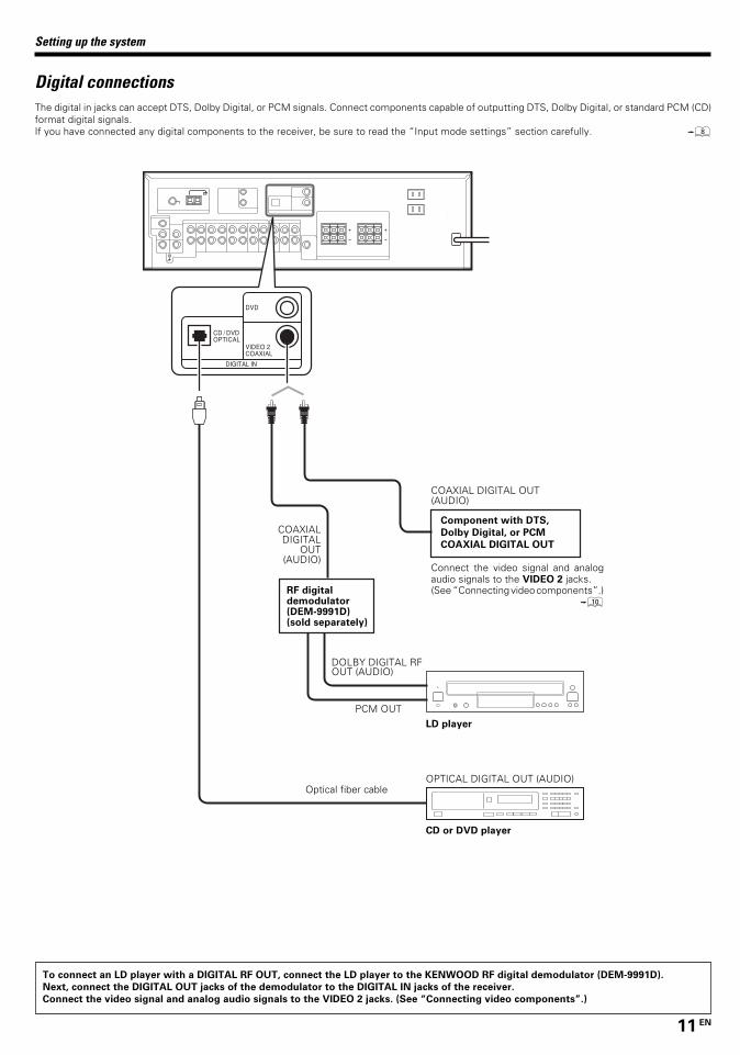
Digital connectionsThe digital in jacks can accept DTS, Dolby Digital, or PCM signals. Connect components capable of outputting DTS, Dolby Digital, or standard PCM (CD)format digital signals.If you have connected any digital components to the receiver, be sure to read the “Input mode settings” section carefully. 8
Component with DTS,
Dolby Digital, or PCM
COAXIAL DIGITAL OUT
COAXIALDIGITAL
OUT(AUDIO)
DOLBY DIGITAL RFOUT (AUDIO)
LD player
PCM OUT
RF digitaldemodulator(DEM-9991D)(sold separately)
CD or DVD player
OPTICAL DIGITAL OUT (AUDIO)Optical fiber cable
COAXIAL DIGITAL OUT(AUDIO)
Connect the video signal and analogaudio signals to the VIDEO 2 jacks.(See “Connecting video components”.)
0
To connect an LD player with a DIGITAL RF OUT, connect the LD player to the KENWOOD RF digital demodulator (DEM-9991D).
Next, connect the DIGITAL OUT jacks of the demodulator to the DIGITAL IN jacks of the receiver.
Connect the video signal and analog audio signals to the VIDEO 2 jacks. (See “Connecting video components”.)
*5197/08-16/EN 26/03/2002, 2:51 PM11

12 EN
VIDEO 2COAXIAL
DVD
DIGITAL IN
CD / DVDOPTICAL
VOLTAGESELECTOR
AC110V-120V / 220V-240V~
50 / 60HzSWITCHED
TOTAL 90W MAX.
AC OUTLETS
AC 220-240V~
AC 110-120V~
SPEAKERS
SURROUNDSPEAKERS
(8-16Ω)
CENTER SPEAKER
(8-16Ω)
FRONTSPEAKERS
(8-16Ω)
GRAYWHITE GREEN BLUERED
L CR LR
CENTER
SUB WOOFERPRE OUT
SUBWOOFER SURROUNDFRONT
DVD / 6CH INPUT
PLAY INVIDEO 2
DVD
AUDIO
REC OUT PLAY INVIDEO1
PHONO REC OUT PLAY INMD / TAPE
CD / DVD
L
R
GND
VIDEO 1OUT
VIDEO 1IN
VIDEO
VIDEO 2IN
DVDIN
MONITOROUT
ANTENNA
GND
AMFM75Ω 75µs
AM 10kHzFM 100kHz
50µsAM 9kHzFM 50kHz
DE-EMPHASISCHANNELSPACE
SYSTEMCONTROL
+
-
+
-
CENTER
SUBWOOFER SURROUNDFRONT
DVD / 6CH INPUT
VIDEO 2COAXIAL
DVD / 6CH
DIGITAL IN
CD / DVDOPTICAL
VIDEO 1OUT
VIDEO 1IN
VIDEO
VIDEO 2IN
DVDIN
MONITOROUT
Setting up the system
Connecting a DVD player (6-channel input) (For VR-615/KRF-V5060D only)
CAUTIONBe sure to adhere to the following, or proper ventilation will be blocked causing damage or fire hazard.
• Do not place any object impairing heat radiation onto the top of the unit.• Leave a space around the unit (from the largest outside dimension including projection) equal or greater than, shown below.
Top panel : 50 cm Side panel : 10 cm Back panel : 10 cm
If you have connected a DVD player to the receiver with digital connection, be sure to read the “Input mode settings” section carefully. 8
SURROUNDOUT L/R
VIDEO OUT(Yellow RCA
pin cord)
DVD player
SUBWOOFEROUT
CENTER OUT
FRONTOUT L/R
COAXIALDIGITAL
OUT(AUDIO)
*5197/08-16/EN 26/03/2002, 2:51 PM12

13 EN
VIDEO 2COAXIAL
DVD
DIGITAL IN
CD / DVDOPTICAL
VOLTAGESELECTOR
AC110V-120V / 220V-240V~
50 / 60HzSWITCHED
TOTAL 90W MAX.
AC OUTLETS
AC 220-240V~
AC 110-120V~
SPEAKERS
SURROUNDSPEAKERS
(8-16Ω)
CENTER SPEAKER
(8-16Ω)
FRONTSPEAKERS
(8-16Ω)
GRAYWHITE GREEN BLUERED
L CR LR
CENTER
SUB WOOFERPRE OUT
SUBWOOFER SURROUNDFRONT
DVD / 6CH INPUT
PLAY INVIDEO 2
DVD
AUDIO
REC OUT PLAY INVIDEO1
PHONO REC OUT PLAY INMD / TAPE
CD / DVD
L
R
GND
VIDEO 1OUT
VIDEO 1IN
VIDEO
VIDEO 2IN
DVDIN
MONITOROUT
ANTENNA
GND
AMFM75Ω 75µs
AM 10kHzFM 100kHz
50µsAM 9kHzFM 50kHz
DE-EMPHASISCHANNELSPACE
SYSTEMCONTROL
+
-
+
-
SUB WOOFERPRE OUT
CENTER SPEAKER
(8-16Ω)
FRONTSPEAKERS
(8-16Ω)
+
-
CR L
RED WHITE GREEN
SURROUNDSPEAKERS
(8-16Ω)
SUB WOOFERSPEAKER
(8-16Ω)
+
-
R
GRAY
L
BLUE PURPLE
SW
VR-615/KRF-V5560D
VR-605/KRF-V5060D/KRF-V4060D
SURROUNDSPEAKERS
(8-16Ω)
+
-
R
GRAY
L
BLUE
Setting up the system
Connecting the speakers
Center
Speaker
Front Speakers
Right Left
Sub wooferPowered
sub woofer
(For VR-605/
KRF-V5060D/
V4060D)
Right Left
(Be sure to connect bothsurround speakers)
Surround Speakers
*5197/08-16/EN 26/03/2002, 2:51 PM13

14 EN
1 Strip coating. 2 Push the lever.
3 Insert the cord. 4 Return the lever.
VIDEO 2COAXIAL
DVD
DIGITAL IN
CD / DVDOPTICAL
VOLTAGESELECTOR
AC110V-120V / 220V-240V~
50 / 60HzSWITCHED
TOTAL 90W MAX.
AC OUTLETS
AC 220-240V~
AC 110-120V~
SPEAKERS
SURROUNDSPEAKERS
(8-16Ω)
CENTER SPEAKER
(8-16Ω)
FRONTSPEAKERS
(8-16Ω)
GRAYWHITE GREEN BLUERED
L CR LR
CENTER
SUB WOOFERPRE OUT
SUBWOOFER SURROUNDFRONT
DVD / 6CH INPUT
PLAY INVIDEO 2
DVD
AUDIO
REC OUT PLAY INVIDEO1
PHONO REC OUT PLAY INMD / TAPE
CD / DVD
L
R
GND
VIDEO 1OUT
VIDEO 1IN
VIDEO
VIDEO 2IN
DVDIN
MONITOROUT
ANTENNA
GND
AMFM75Ω 75µs
AM 10kHzFM 100kHz
50µsAM 9kHzFM 50kHz
DE-EMPHASISCHANNELSPACE
SYSTEMCONTROL
+
-
+
-
ANTENNA
GND
AMFM75Ω
Setting up the system
Connecting the terminals
Speaker impedanceAfter confirming the speaker impedance indications printed on therear panel of the receiver, connect speakers with matching imped-ance ratings. Using speakers with a rated impedance other than thatindicated on the rear panel of the receiver could result in malfunctionsor damage to the speakers or receiver.
• Never short circuit the + and – speaker cords.• If the left and right speakers are connected inversely or the speaker
cords are connected with reversed polarity, the sound will beunnatural with ambiguous acoustic imaging. Be sure to connect thespeakers correctly.
Connecting the antennas
AM loop antennaThe supplied loop antenna is for use indoors. Place it as far as possiblefrom the receiver, TV set, speaker cords and power cord, and adjustthe direction for best reception.
FM indoor antennaThe supplied indoor antenna is for temporary use only. For stablesignal reception we recommend using an outdoor antenna. Discon-nect the indoor antenna when you connect one outdoors.
FM outdoor antennaLead the 75Ω coaxial cable connected to the FM outdoor antenna intothe room and connect it to the FM 75Ω terminal.
AM antenna terminal connections1 Push lever. 2 Insert cord. 3 Release lever.
FM antenna terminal connectionsInsert cord.
Use an antennaadaptor(Commerciallyavailable)
Attach to the stand
AM loop antenna
FM indoor antenna
FM outdoor antenna
*5197/08-16/EN 26/03/2002, 2:51 PM14

15 EN
Receiver
Cassette deckor MD recorder
CD player
Record player
Connecting system control cords after connecting a KENWOOD
audio component system lets you take advantage of convenient
system control operations.
This unit is compatible only with the [SL-16] mode. The system
control operation is not available if the unit is connected in the
[XS8], [XS], or [XR] connection mode.
If your component has the mode select switch, set the connected
components to the [SL16] mode.
• You may connect the system control cord to either the up or downjack.
EXAMPLE: [SL16] mode connections
The underlined portion represents the setting of the system controlmode.
• In order to take advantage of the system control operations, thecomponents must be connected to the correct jacks. To use a CDplayer it must be connected to the CD jacks. To use a cassette deck(or MD recorder) it must be connected to the MD/TAPE jacks.When using more than one CD player (etc.) only the one connectedto the specified jacks may be connected for system control.
• Some CD players and cassette decks are not compatible with the[SL16] system control mode. Do not make system connectionswith equipment that is not [SL16] compatible.
• Some MD players are not system control compatible. You cannotmake system control connections to this kind of equipment.
Notes1. [SL16] equipment cannot be combined with [XR], [XS], and [XS8]
equipment for system operations. If your equipment consists ofthis kind of combination, please do not connect any system controlcords. Even without system control cords, normal operations canbe carried out without effecting performance.
2. Do not connect system control cords to any components otherthan those specified by KENWOOD. It may cause a malfunctionand damage your equipment.
3. Be sure the system control plugs are inserted all the way in to thesystem control terminals.
Connecting the system control
Setting up the system
SYSTEM CONTROLcord
SYSTEM CONTROL OPERATIONSRemote Control
Lets you operate this unit with the system remote supplied with thereceiver.
Automatic Operation
When you start playback from a source component, the input selectoron this unit switches to that component automatically.
Synchronized Recording
Lets you synchronize recording with the start of playback whenrecording from CD, MD or analog discs.SYSTEM
CONTROL
SYSTEMCONTROLcord
[SL16]
[SL16] [XS] [XS8] [XR]
[SL16] [XS] [XS8]
[XS]
*5197/08-16/EN 26/03/2002, 2:51 PM15

16 EN
6 m
Speaker placement
Front speakers : Place to the front left and right of the listeningposition. Front speakers are required for all surround modes.Center speaker : Place front and center. This speaker stabilizes thesound image and helps recreate sound motion. Required for surroundplayback.Surround speakers : Place to the direct left and right, or slightlybehind, the listening position at even heights, approximately 1 meterabove the ears of the listeners. These speakers recreate soundmotion and atmosphere. Required for surround playback.Subwoofer : Reproduces powerful deep bass sounds.
• Although the ideal surround system consists of all the speakerslisted above, if you don't have a center speaker or a subwoofer, youcan divide those signals between the available speakers in thespeaker settings steps to obtain the best possible surround repro-duction from the speakers you have available. &
Operation
When the STANDBY indicator is lit, the power turns ON when youpress the POWER ( ) key on the remote control. When the powercomes ON, press the key you want to operate.
• When pressing more than one remote control key successively,press the keys securely by leaving an interval of 1 second or morebetween keys.
Notes1. The supplied batteries may have shorter lives than ordinary batter-
ies due to use during operation checks.2. When the remote-controllable distance gets shorter than before,
replace both batteries with new ones.3. Placing the remote sensor in direct sunlight, or in direct light from
a high frequency fluorescent lamp may cause a malfunction.In such a case, change the location of the system installation toprevent malfunction.
Setting up the system
Preparing the remote control
Channel space switching(Except for the U.S.A., Canada, U.K., Europe and Australia)
The space between radio channels has been set to the one thatprevails in the area to which the system is shipped. However, if thecurrent channel space setting does not match the setting in the areawhere the system is to be used, for instance when you move fromarea 1 or area 2 shown in the following table or vice versa, properreception of AM/FM broadcasts cannot be expected. In this case,change the channel space setting in accordance with your area byreferring to the following table.
Turn the power OFF by pressing the POWER key before moving theswitch level. Move the switch lever to match your area with a smallscrewdriver or other pointed tool, then turn the power ON again.
1.
2.
CHANNELSpace FrequencyArea
U.S.A., Canada and SouthAmerican countries
Other countries
FM: 100 kHzAM: 10 kHz
FM: 50 kHzAM: 9 kHz
Loading the batteries1 Remove the cover. 2 Insert the batteries.
3 Close the cover.
• Insert two AA-size (R6) batteries as indicated by the polarity mark-ings.
Frontspeaker
Subwoofer
Surroundspeaker
Center speaker
Listeningposition
FRONT
D
PLAY INVIDEO 2
DVD
AUDIO
REC OUT PLAY INVIDEO1
PHONO REC OUT PLAY INMD / TAPE
CD / DVD
L
R
VIDEO 1OUT
VIDEO 1IN
VIDEO
VIDEO 2IN
DVDIN
MONITOROUT
ANTENNA
GND
AMFM75Ω
SYSTEMCONTROL
DE-EMPHASISCHANNELSPACE
75µsAM 10kHzFM 100kHz
50µsAM 9kHzFM 50kHz
75µsAM 10kHzFM 100kHz
50µsAM 9kHzFM 50kHz
DE-EMPHASISCHANNELSPACE
12
Operating range(Approx.)
Remote sensor
Infrared ray system
*5197/08-16/EN 26/03/2002, 2:51 PM16

17 EN
Preparing for surround sound
Speaker settingsTo enable you to obtain optimum enjoyment from the receiver’s listeningmodes, make sure to complete the speaker settings (subwoofer, front,center, and surround speakers) as described below.For VR-615 (HTB model), do not select “LRG” (large) for front, center,and surround speakers as this will cause the speakers to malfunction.
1Turn on the power to this receiver by pressing POWER ON/STANDBY (for VR-605/615) or POWER ON/OFF and ON/STANDBY (for KRF-V5060D/V4060D/V5560D) or POWER key.
2Press the SET UP key to enter the SET UP mode and use theMULTI CONTROL knob or keys for the following displays.
1 SP SETUP
2 TESTTONE
3 DISTANCE
4 EXIT
The flow of the SET UP is as follows;
SP SETUP TESTTONE DISTANCE EXIT
Front
Center
Surround
Subwoofer
Front
Center
Surround
SubwooferRe-mix
LCR
SRSLSW
L
C
R
SR
SL
SW
MANUALAUTO
3Select a speaker system.
1 Select SP SETUP and press the SET UP key again so that the
subwoofer setting indication “SUBW ON” appears.
2 Use the MULTI CONTROL knob or keys to select the
appropriate subwoofer setting.
1 SUBW ON : Subwoofer setting mode to the receiver is ON.2 SUBW OFF : Subwoofer setting mode to the receiver is OFF.
• The initial setting is “SUBW ON”.• When the setting “SUBW OFF” is selected, the front speakers
are automatically set to “FRNT LRG” and the procedure skips tostep 6.Before step 6, press the SET UP key to accept the setting.
• When subwoofer output sound is required, select “FRNT NML”.
3 Press the SET UP key to accept the setting.
• The front speakers setting indication “FRNT LRG” appears.
4 Use the MULTI CONTROL knob or keys to select the appropriate
front speakers setting.
1 FRNT NML (normal) : Average size front speakers areconnected to the receiver.
2 FRNT LRG (large) : Large front speakers are connected tothe receiver.
• For VR-615 (HTB model), do not select “LRG” (large) for frontspeaker as this will cause the speaker to malfunction.
• For “FRNT LRG” selection, no sound will be heard from subwooferspeaker even when it is set to ON. However, if you selectCINEMA EQ when subwoofer is selected, you will be able tohear sound from the subwoofer.When in STEREO mode, the sound goes directly to front speaker.
5 Press the SET UP key to accept the setting.
• The center speaker setting indication “CNTR” appears.
6 Use the MULTI CONTROL knob or keys to select the appropriate
center speaker setting.
If you selected “LRG” as the front speakers setting,
1 CNTR NML (normal) : An average size center speaker isconnected to the receiver.
2 CNTR LRG (large) : A large center speaker is connected tothe receiver.
3 CNTR OFF : Center speaker setting mode to thereceiver is OFF.
• For VR-615 (HTB model), do not select “LRG” (large) for centerspeaker as this will cause the speaker to malfunction.
If you selected “NML” as the front speakers setting,
1 CNTR ON : Center speaker setting mode to thereceiver is ON.
2 CNTR OFF : Center speaker setting mode to thereceiver is OFF.
7 Press the SET UP key again to accept the setting.
•The surround speaker setting indication “SURR” appears.
8 Use the MULTI CONTROL knob or keys to select the
appropriate surround speaker setting.
If you selected “LRG” as the center speaker setting,
1 SURR NML (normal) : Average size surround speakers areconnected to the receiver.
2 SURR LRG (large) : Large surround speakers are connectedto the receiver.
3 SURR OFF : Surround speaker setting mode to thereceiver is OFF.
Continued to next page
MULTI CONTROL
(KRF-V5060D/V4060D/V5560D)
SET UPPOWER ON/OFF
SET UP
MULTI CONTROL
POWER
ON/STANDBY(KRF-V5060D/ V4060D/
V5560D)(VR-605/615)
POWERON/STANDBY
*5197/17-21/EN 26/03/2002, 2:52 PM17

18 EN
Preparing for surround sound
• For VR-615 (HTB model), do not select “LRG” (large) for surroundspeaker as this will cause the speaker to malfunction.
If you have selected other than “LRG” as the center speaker
setting,
1 SURR ON : Surround speaker setting mode to the receiver isON.
2 SURR OFF : Surround speaker setting mode to the receiver isOFF.
9 Press the SET UP key again to accept the setting.
• The subwoofer re-mix setting indication “SW RE-MIX” scrollsacross the display.
“SW RE-MIX” scrolls across the display.
• If subwoofer is turned OFF, subwoofer re-mix setting is notvisible.
0 Use the MULTI CONTROL knob or keys to select the
appropriate subwoofer remix setting.
1 RMX ON : Subwoofer re-mix set mode to the receiver is ON.2 RMX OFF : Subwoofer re-mix set mode to the receiver is OFF.
! Press the SET UP key to accept the setting.
• The receiver enters the speaker volume level adjustmentmode.
• In step 4 and 5, indications appear only for the selectedchannels of the speakers that require adjusting.
4Adjust the speaker volume level.From your usual listening position, adjust the volume levels. Thevolume levels from each speaker should be the same.
1 Press the SET UP key to begin TEST TONE.
1 AUTO
2 MANUAL
2 The selection of AUTO/MANUAL TEST TONE is done by the
MULTI CONTROL knob or keys.
Press the SET UP key again to select either AUTO or MANUAL.
Use the MULTI CONTROL knob or keys to adjust the volume
level of the test tone output from the speaker channel to be
adjusted.
For AUTO selection, the test tone is heard from the speakers
in the following sequence for 2 seconds each:
The channel indication blinks while the test tone is being ouput.
• If you change the volume level settings for the speakers whilelistening to music, the settings referred to on this page are alsochanged. ª
• If the speaker setting selects are OFF, the speaker level settingsare reset.
3 Press the SET UP key.
• The test tone is turned off. The receiver enters the mode forinputting the distance to the speakers.
4 For MANUAL selection, press the SET UP key each time to
select the speaker channel.
5 Input the distance to the speakers.
1 Select the DISTANCE from the set up displays and press the
SET UP key again.
2 Measure the distance from the listening position to each of
the speakers.
Jot down the distance to each of the speakers.
Distance to front speakers : ____ feet (meters)Distance to center speaker : ____ feet (meters)Distance to surround speakers : ____ feet (meters)
3 Use the MULTI CONTROL knob or keys to select the distance
to the front speakers.
The speaker indicator to be adjusted blinks.
Indication in feet Indication in meters• The allowable setting range is 1 to 30 feet (0.3m to 9.0m) ,
adjustable in 1 foot (0.3m) increments.
4 Press the SET UP key to accept the settings.
5 Repeat steps 3 and 4 to input the distance for each of the
speakers.
6 Setup is complete when the input indication appears.
• The speakers you have selected should appear on the display.Confirm that all the speakers have been correctly selected.
7 Press the SET UP key to exit the SET UP mode.
Input level adjustment (analog sources only)If the input level of an analog source signal is too high, the CLIP indicatorwill blink to indicate the source signal. Adjust the input level.
1 Use the INPUT SELECTOR knob to select the source of which the
input level you want to adjust.
• You can store a separate input level for each input source.
2 Press the SOUND key repeatedly until the “INPUT” indication
appears.
3 Use the MULTI CONTROL knob or keys to adjust the input level.
• The adjustment mode is displayed for approximately eight sec-onds.
• The input level may be adjusted to any one of three settings: 0dB,-3dB, and -6dB. (The initial setting is 0dB.)
4 Press the SOUND key again to return to the input indication.
*5197/17-21/EN 26/03/2002, 2:52 PM18
19 EN
Listening to a source component
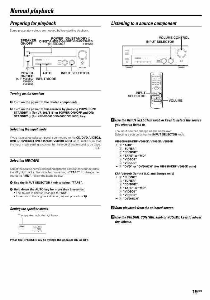
1Use the INPUT SELECTOR knob or keys to select the sourceyou want to listen to.
The input sources change as shown below:Selecting a source using the INPUT SELECTOR knob.
VR-605/615/KRF-V5060D/V4060D/V5560D
1 “AUX”
2 “TUNER”
3 “CD/DVD”
4 “TAPE” or “MD”
5 “VIDEO1”
6 “VIDEO2”
7 “DVD” or “DVD/6CH” (for VR-615/KRF-V5060D only)
KRF-V5060D (for the U.K. and Europe only)
1 “PHONO”
2 “TUNER”
3 “CD/DVD”
4 “TAPE” or “MD”
5 “VIDEO1”
6 “VIDEO2”
7 “DVD/6CH”
2Start playback from the selected source.
3Use the VOLUME CONTROL knob or VOLUME keys to adjustthe volume.
Normal playback
Some preparatory steps are needed before starting playback.
Turning on the receiver
1 Turn on the power to the related components.
2 Turn on the power to this receiver by pressing POWER ON/
STANDBY (for VR-605/615) or POWER ON/OFF and ON/
STANDBY (for KRF-V5060D/V4060D/V5560D) key.
Selecting the input mode
If you have selected a component connected to the CD/DVD, VIDEO2,
DVD or DVD/6CH (VR-615/KRF-V5060D only) jacks, make sure thatthe input mode setting is correct for the type of audio signal to be used.
8
Selecting MD/TAPE
Select the source name corresponding to the component connected tothe MD/TAPE jacks. The initial factory setting is “TAPE”. To change thesource to “MD”, follow the steps below:
1 Use the INPUT SELECTOR knob to select “TAPE”.
2 Hold down the AUTO key for more than 2 seconds.
• The source indication changes to “MD”.• To return to the original indication, repeat procedure 2.
Setting the speaker status
Press the SPEAKER key to switch the speaker ON or OFF.
Preparing for playback
The speaker indicator lights up.
AUTO
INPUT MODE
INPUT SELECTOR
(KRF-V5060D/V4060D/V5560D)
POWERON/OFF
SPEAKER ON/OFF
ON/STANDBY(KRF-V5060D/ V4060D/
V5560D)(VR-605/615)
POWERON/STANDBY INPUT SELECTOR
VOLUME CONTROL
INPUTSELECTOR
VOLUME
*5197/17-21/EN 26/03/2002, 2:52 PM19

20 EN
Normal playback
Adjusting the sound
Adjusting the TONE (remote control only)You can adjust the sound quality when the receiver is in the PCM stereoand analog stereo mode.
1 Press the TONE key to select the TONE mode.
2 Use the MULTI CONTROL knob or keys to select TONE ON/OFF.
3 Press the TONE key for the following displays.
1 TONE : Tone setting mode is ON.2 BASS : Select this to adjust the low frequency range.3 TREB : Select this to adjust the high frequency range.
4 Use the MULTI CONTROL knob or keys to adjust the sound
quality.
• The bass and treble levels are adjustable from -10 to +10 in 2 stepincrements.
• The adjustment item is displayed for approximately 8 seconds.• If CINEMA EQ is turned ON, TONE function will not be available.
Once-touch low frequency emphasis (BASS BOOST)(remote control only)You can adjust the sound quality when the receiver is in the PCM stereoand analog stereo modes.
Press the BASS BOOST key.
• Press the key once to select the maximum (+10) low frequencyemphasis setting.
• TONE will automatically be turned ON.• This key does not function when the receiver is in the sound quality
or ambience effects adjustment mode.
Switching back the previous setting
Press the BASS BOOST key again.
Adjusting the LOUDNESS mode (remote control only)You can adjust the Loudness function which controls the low volumesettings to maintain the music’s richness. The adjustment can be madewhen the receiver is in the PCM stereo and analog stereo mode.
Press the LOUDNESS key to turn the LOUDNESS setting ON.
To cancel
Press the LOUDNESS key again so that the “LOUDNESS” indica-
tor goes off.
Muting the soundThe MUTE key lets you mute the sound of the speakers.
Press the MUTE key.
To cancel
Press the MUTE key again so that the “MUTE” indicator goes off.
• MUTE ON can also be deactivated by turning the volume controlknob.
CINEMA EQ modeYou can enjoy a more impressive sound effect when you switchCINEMA EQ ON during Dolby Digital and DTS playback.
Press the CINEMA EQ key.
“CINEMA EQ” will scroll across the display.
• When CINEMA EQ is turned ON, subwoofer remix’s function willalso be effective.
• If REC MODE is ON or TREBLE’s level is -6 or below, CINEMA EQfunction will not be available.
To cancel
Press the CINEMA EQ key again so that the “CINEMA EQ”
indicator goes off and displays “OFF”.
• When CINEMA EQ is turned OFF, the setting will remain until thenext selection is made.
Listening with headphones
1 Press the SPEAKERS ON/OFF key so that the speaker indicator
goes off.
• If you turn off all of the speakers when in surround mode, thesurround mode will be canceled as well, resulting in stereo play-back.
2 Connect headphones to the PHONES jack.
PHONES
3 Use the VOLUME CONTROL knob or VOLUME keys to adjust the
volume.
Make sure the SP indicator is turned OFF.
VOLUMEMUTE
BASS BOOST
MULTI CONTROL
CINEMA EQVOLUME CONTROL
PHONES MULTI CONTROL
TONECINEMA EQ
LOUDNESS
SPEAKERS ON/OFF
MUTE
*5197/17-21/EN 26/03/2002, 2:52 PM20

21 EN
Recording
Recording audio (analog sources)
Recording a music source
1 Use the INPUT SELECTOR knob to select the source (other than
“MD/TAPE”) you want to record.
2 Set the MD or TAPE recorder to record.
3 Start playback, then start recording.
Recording video
1 Use the INPUT SELECTOR to select the video source (other than
“VIDEO1”) you want to record.
2 Set the video deck connected to VIDEO 1 to record.
• Select the REC MODE to record a digital input source.
3 Start playback, then start recording.
• Recording may not be normal for some video software. This is dueto the copy guard condition. ‹
Recording audio (digital sources)
Switch on the REC MODE to record a digital input source.Usually use the A-REC (Auto-Record) MODE to record audio inputsources. When the digital mode changes during recording in the A-REC
MODE , the audio input source may be interrupted momentarily.
Recording music in A-REC or M-REC mode
INPUT SELECTOR
DIMMER
1 Use the INPUT SELECTOR knob to select the source [CD/DVD,
DVD or DVD/6CH (VR-615/KRF-V5060D only) or VIDEO2] you
want to record.
2 Set the MD or TAPE recorder to record.
3 Press and hold the DIMMER key for more than 2 seconds to select
the A-REC or M-REC mode during digital input.
• The mode changes every 2 seconds as shown below.
1 Rec mode off : The digital input record mode is switched
off.
2 A-REC : The digital input signals (DTS, Dolby
Digital, or PCM) are identified
automatically and converted into stereo
signals that are ready for recording.
3 M-REC : The input signal type at the moment this
mode is selected is held throughout this
mode.
For A-REC mode:
For M-REC mode:
4 Start playback, then start recording.
• If the audio reproduction stops in the middle due to change in theinput signals, etc., press the DIMMER key.
INPUT SELECTOR
*5197/17-21/EN 26/03/2002, 2:52 PM21

22 EN
(For the U.K. and Europe only)Using RDS (Radio Data System)
RDS is a system that transmits useful information (in the form of digitaldata) for FM broadcasts along with the broadcast signal. Tuners andreceivers designed for RDS reception can extract the information fromthe broadcast signal for use with various functions, such as automaticdisplay of the station name.
RDS functions:PTY (Program TYpe Identification) Search ∞Automatically tunes to a station that is currently broadcasting thespecified program type (genre).
PS (Program Service Name) Display
Automatically displays the station name transmitted by the RDSstation.
RDS AUTO MEMORY function ¢Automatically selects and stores up to 40 RDS stations in the presetmemory.If fewer than 40 RDS stations have been stored in the preset memory,regular FM stations will be stored in the remaining places.
Radio Text function
Displays the radio text data transmitted by some RDS stations whenyou press the RDS DISPLAY key. There is “NO RT” display if no textdata is transmitted.
The “RDS” indicator lights up when an RDS broadcast (signal) isreceived.
NoteSome functions and function names may differ for certain countriesand areas.
Before using a function utilizing the RDS, be sure to perform the RDSAuto Memory operation by referring to the description in “PresettingRDS stations (RDS AUTO MEMORY)”. ¢
Listening to radio broadcasts
The receiver can store up to 40 stations in the memory and recall themby one-touch operation.Radio stations can be classified into RDS (Radio Data System) stationsand other stations. To listen to or store RDS stations in the presetmemory see “Using RDS (Radio Data System)”. (For the U.K. and Europeonly)
Tuning (non-RDS) radio stations
“AM” or “FM” indicatorappears in the display
“AUTO” indicator lightsup in the display.
1Use the INPUT SELECTOR knob or TUNER key to select thetuner.
2Use the BAND key to select the desired broadcast band.
Each press switches the band
as follows:
1 FM
2 AM
3Use the AUTO key to select the desired tuning method.
Each press switches the tuning method as follows:
1 AUTO lit (auto tuning)2 AUTO not lit (manual tuning)
• Normally, set to “AUTO” (auto tuning). If the radio waves are weakand there is a lot of interference, switch to manual tuning. (Withmanual tuning, stereo broadcasts will be received in monaural.)
4Use the MULTI CONTROL knob or keys, or TUNING 1 /¡ keys to select the station.
Auto tuning : The next station is tuned automatically.Manual tuning : Turn the knob (press the key) to select the
desired station.
Frequencydisplay
“TUNED” is displayedwhen a station is received.
“ST.” lights whena broadcast is beingreceived in stereo.
MULTI CONTROL
INPUT SELECTORBAND AUTO
MULTI CONTROL
TUNERAUTOBAND
TUNING 1 / ¡
*5197/22-25/EN 26/03/2002, 2:54 PM22
23 EN
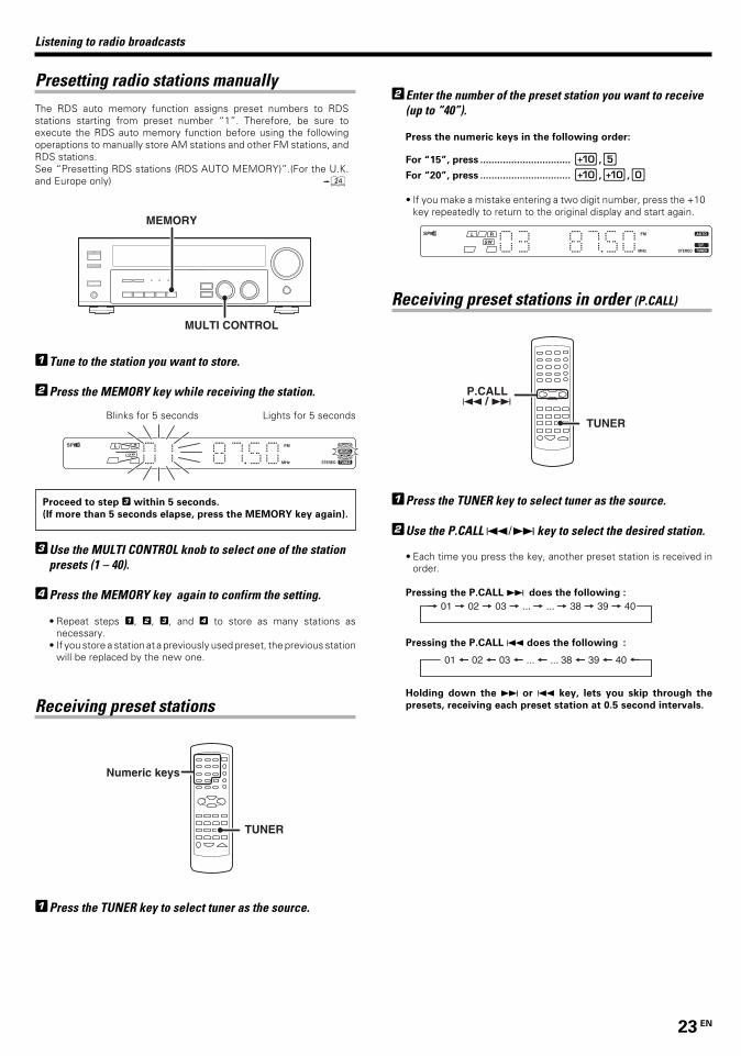
Presetting radio stations manuallyThe RDS auto memory function assigns preset numbers to RDSstations starting from preset number “1”. Therefore, be sure toexecute the RDS auto memory function before using the followingoperaptions to manually store AM stations and other FM stations, andRDS stations.See “Presetting RDS stations (RDS AUTO MEMORY)”.(For the U.K.and Europe only) ¢
MULTI CONTROL
MEMORY
1Tune to the station you want to store.
2Press the MEMORY key while receiving the station.
3Use the MULTI CONTROL knob to select one of the stationpresets (1 – 40).
4Press the MEMORY key again to confirm the setting.
• Repeat steps 1, 2, 3, and 4 to store as many stations asnecessary.
• If you store a station at a previously used preset, the previous stationwill be replaced by the new one.
Receiving preset stations
TUNER
Numeric keys
1Press the TUNER key to select tuner as the source.
Listening to radio broadcasts
2Enter the number of the preset station you want to receive(up to “40”).
Press the numeric keys in the following order:
For “15”, press ................................ 0,5
For “20”, press ................................ 0,0,)
• If you make a mistake entering a two digit number, press the +10key repeatedly to return to the original display and start again.
Receiving preset stations in order (P.CALL)
TUNER
P.CALL 4 / ¢
1Press the TUNER key to select tuner as the source.
2Use the P.CALL 4¥¢ key to select the desired station.
• Each time you press the key, another preset station is received inorder.
Pressing the P.CALL ¢ does the following :
Pressing the P.CALL 4 does the following :
Holding down the ¢ or 4 key, lets you skip through the
presets, receiving each preset station at 0.5 second intervals.
Proceed to step 3 within 5 seconds.
(If more than 5 seconds elapse, press the MEMORY key again).
Blinks for 5 seconds Lights for 5 seconds
*5197/22-25/EN 26/03/2002, 2:54 PM23

24 EN
Listening to radio broadcasts
(For the U.K. and Europe only)Using the RDS DISPLAY key
RDS DISPLAY
Pressing the RDS DISPLAY key changes the contents of thedisplay.
Each press switches the display mode as follows:
1 PS (Program Service name) display
2 RT (Radio Text) display
3 Frequency display
1 PS (Program Service name) display:
The station name is displayed automatically when an RDS broadcastis received.If no PS data was sent, “NO PS” is displayed.
2 RT (Radio Text) display:
Text data accompanying the RDS broadcast scrolls across the display.“NO RT” or “RT----” is displayed if the current RDS station does notprovide RT data.
3 Frequency display:
Displays the frequency of the current station.
(For the U.K. and Europe only)Presetting RDS stations (RDS AUTO MEMORY)
This function automatically stores up to 40 RDS stations in the presetmemory. In order to use the PTY function, the RDS stations must bestored in the preset memory using the RDS AUTO MEMORY function.
INPUT SELECTORBAND AUTO
MEMORY
1Use the INPUT SELECTOR knob to select the tuner.
2Use the BAND key to set the broadcast band to “FM”.
3Press and hold the MEMORY key for more than 2 seconds.
• After a few minutes, up to 40 RDS stations are preset in order fromchannel “01”.
• Stations already stored in the preset memory may be replaced byRDS stations. (i.e., If the RDS AUTO MEMORY function detects 15RDS stations, the stations currently preset at numbers 01~15 willbe replaced by the RDS stations.)
*5197/22-25/EN 26/03/2002, 2:54 PM24
25 EN
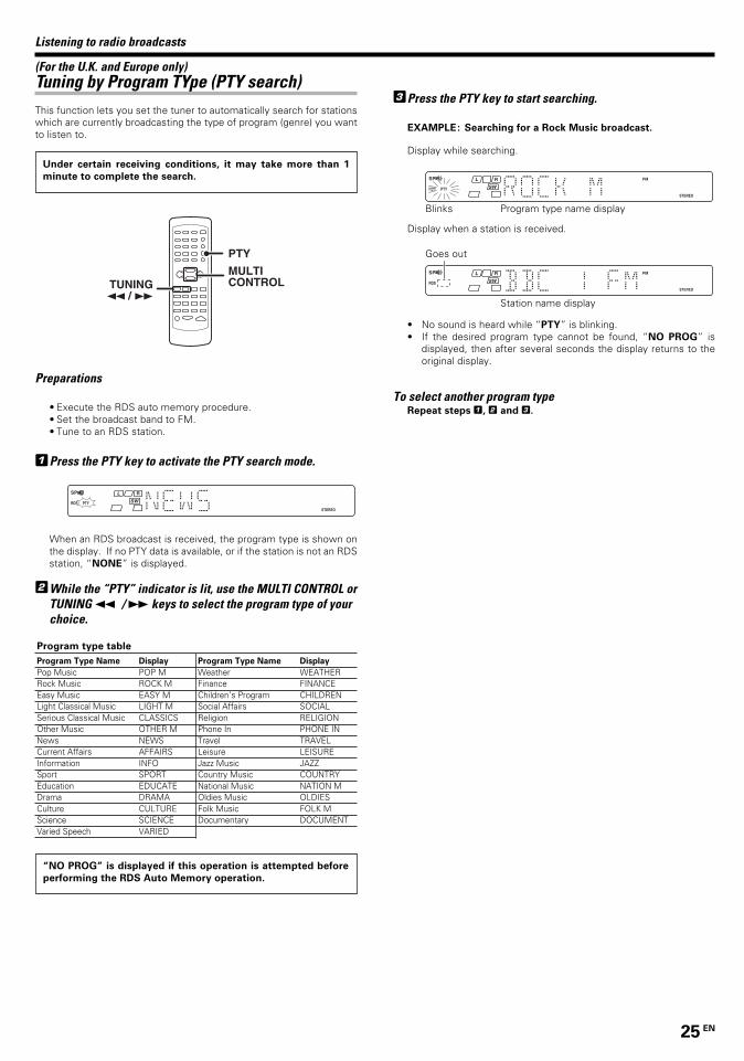
3Press the PTY key to start searching.
EXAMPLE: Searching for a Rock Music broadcast.
Display while searching.
Blinks Program type name display
Display when a station is received.
Station name display
• No sound is heard while “PTY” is blinking.• If the desired program type cannot be found, “NO PROG” is
displayed, then after several seconds the display returns to theoriginal display.
To select another program typeRepeat steps 1, 2 and 3.
Listening to radio broadcasts
Goes out
Under certain receiving conditions, it may take more than 1
minute to complete the search.
“NO PROG” is displayed if this operation is attempted before
performing the RDS Auto Memory operation.
(For the U.K. and Europe only)Tuning by Program TYpe (PTY search)This function lets you set the tuner to automatically search for stationswhich are currently broadcasting the type of program (genre) you wantto listen to.
MULTI CONTROLTUNING
1 / ¡
PTY
Preparations
• Execute the RDS auto memory procedure.• Set the broadcast band to FM.• Tune to an RDS station.
1Press the PTY key to activate the PTY search mode.
When an RDS broadcast is received, the program type is shown onthe display. If no PTY data is available, or if the station is not an RDSstation, “NONE” is displayed.
2While the “PTY” indicator is lit, use the MULTI CONTROL orTUNING 1 / ¡ keys to select the program type of yourchoice.
Program type table
Program Type Name Display
Pop Music POP MRock Music ROCK MEasy Music EASY MLight Classical Music LIGHT MSerious Classical Music CLASSICSOther Music OTHER MNews NEWSCurrent Affairs AFFAIRSInformation INFOSport SPORTEducation EDUCATEDrama DRAMACulture CULTUREScience SCIENCEVaried Speech VARIED
Program Type Name Display
Weather WEATHERFinance FINANCEChildren’s Program CHILDRENSocial Affairs SOCIALReligion RELIGIONPhone In PHONE INTravel TRAVELLeisure LEISUREJazz Music JAZZCountry Music COUNTRYNational Music NATION MOldies Music OLDIESFolk Music FOLK MDocumentary DOCUMENT
*5197/22-25/EN 26/03/2002, 2:54 PM25

26 EN
DTSThe DTS multi-channel audio format is available on CD, LD and DVDsoftware. DTS is a strictly digital format and cannot be decoded insidemost CD, LD or DVD players. For this reason, if you attempt to listento DTS encoded software through the analog output of your new CD,LD or DVD player, you will experience digital noise in most cases. Thisnoise can be quite loud if the analog output is connected directly to ahigh power amplification system. Proper measures for playing thedigital output as described below should be taken to avoid thissituation. To enjoy DTS Digital Surround playback, an external 5.1channel DTS Digital Surround decoder system or an amplifier with abuilt-in DTS Digital Surround decoder must be connected to the digitaloutput (S/P DIF, AES/EBU or TosLink) of a CD, LD or DVD player.All models are incorporated with the DTS decoder.
* LFE = Low Frequency Effects. This channel delivers separate non-directional bass signals to the subwoofer for more dynamic deep basssound effects.DTS has a .1 or LFE channel.The indication “LFE” appears in the display when a signal is beinginput for this channel.
Ambience effects
This receiver is equipped with listening modes that allow
you to enjoy an enhanced sonic ambience with a variety
of video sources.
In order to obtain the optimum effect from the surround
modes, make sure to input the proper speaker settings
beforehand. &
Surround modes
“DTS” and “DTS Digital Surround” are trademarks ofDigital Theater Systems, Inc.
Manufactured under license from Dolby Laboratories. “Dolby”, “ProLogic” and the double-D symbol are trademarks of Dolby Laborato-ries.
Dolby DigitalThe Dolby Digital surround format lets you enjoy up to 5.1 channelsof digital surround sound from Dolby Digital program sources (suchas Laserdisc or DVD software marked ). Compared withprevious Dolby surround, Dolby Digital provides even better soundquality, greater spatial accuracy, and improved dynamic range.
NoteAlthough a full set of speakers (front left, right, and center, surroundleft and right, and a subwoofer) is required for true 5.1 channel DolbyDigital surround sound, this receiver lets you enjoy Dolby Digital (andDolby Surround) program sources, even if you connect only the frontspeakers.
* LFE = Low Frequency Effects. This channel delivers separate non-directional bass signals to the subwoofer for more dynamic deepbass sound effects.Although only Dolby Digital soundtracks incorporate a separate lowfrequency channel, connecting a subwoofer will also improve deepbass performance in the other surround modes.The indication “LFE” appears in the display when a signal is beinginput for this channel.
Center speaker
Front speaker (L, R)
Surround speaker (L, R)
Subwoofer (SW)*
*Optional in this mode.
Center speaker
Front speaker (L, R)
Surround speaker (L, R)
Subwoofer (SW)*
*Optional in this mode.
Dolby PRO LOGIC IIDolby Pro Logic II was designed specifically to provide a new senseof spatiality, directionality and articulation of sounds from DolbySurround encoded sources (such as video and Laserdisc softwaremarked ). This is achieved with an intelligent, built-infeedback logic design, a matrix surround decoding and the decodingof stereo, full bandwidth surround outputs. The PRO LOGIC II modesprogrammed into this receiver are “MOVIE”, “MUSIC” and “PROLOGIC”. The “MOVIE” mode of the PRO LOGIC II has presetcharacteristics to produce a calibrated, high-level surround soundplayback while the “MUSIC” mode has user-adjustable characteris-tics to offer the three optional controls, like “Dimension”, “CenterWidth” and “Panorama” modes to allow optimization of thesoundfields as desired. The “Dimension” control allows the user togradually adjust the soundfield either towards the front or towardsthe rear; the “Center Width” control allows various adjustment of theleft-center-right speakers’ balance; the “Panaroma” extends thefront stereo image to include the surround speakers for an exciting“wraparound” effect with side wall imaging.
Center speaker
Front speaker (L, R)
Surround speaker (L, R)
Subwoofer (SW)
*5197/26-30/EN 26/03/2002, 2:56 PM26

27 EN
Ambience effects
DVD 6-channel mode (For VR-615/KRF-V5060D only)Using a DVD player or the like equipped with six (5.1) output channelsand the receiver, you can enjoy multi-channel encoded DVD sourcematerial in all its splendor. Since the source signals are digital andeach channel is input independently, the resulting sound quality,sense of spaciousness, and dynamic range are superb.
*LFE = Low Frequency Effects. This channel delivers separate non-directional bass singnals to the subwoofer for more dynamic deepbass sound effects.
DSP modeThe DSP mode lets you add the atmosphere of a live concert or hall toalmost any type of program source. These modes are particularlyeffective when used with stereo program sources, like CD, television,and FM radio. You might enjoy trying the ARENA, JAZZ CLUB, THE-ATER, STADIUM or DISCO mode the next time you watch a concert orsporting event!
What's DSP?DSP stands for Digital Signal Processor.The way a sound is heard in an actual environment depends on avariety of different factors. One of the most important is reverbera-tion (the act of decaying elements of sound echoing in variousplaces).The DSP modes produce the feeling of presence by using the DSP tocreate reverberation, without spoiling the sound quality of the originalsignal.
Center speaker
Front speaker (L, R)
Surround speaker (L, R)
Subwoofer (SW)
Center speaker
Front speaker (L, R)
Surround speaker (L, R)
Subwoofer (SW)*
*5197/26-30/EN 26/03/2002, 2:56 PM27

28 EN
Surround playThe DTS compatible models can reproduce a CD, DVD, or LD carrying theDTS mark.DOLBY DIGITAL can be used when playing DVD or LD software bearingthe mark and DOLBY DIGITAL format digital broadcasts (etc.).DOLBY PRO LOGIC can be used when playing video, DVD, or LDsoftware bearing the mark.
INPUT SELECTORINPUT MODE
LISTEN MODE
INPUTSELECTOR
LISTEN MODE
Preparations
•Turn ON related components.•Complete “Preparing for surround sound” (speaker settings).&• Use the INPUT SELECTOR to select the component you wish to
play back with surround sound.• Use the INPUT MODE key to select the input mode (analog or
digital) for the source you wish to play back. 8• Noise will be produced when a DTS source is played by selecting the
analog input.
1Start playing the video software.
2Press the LISTEN MODE key to select the listening mode.
The listening mode settings are stored separately for each input. If theinput mode is set to full auto (“AUTO DETECT” lights), the receiverselects the optimal listening mode automatically based on the type ofinput signal and the speaker settings.
Each press of the LISTEN MODE key switches the setting as
listed below.
The listening mode settings are different depending on the type
of input signal.
When the DOLBY DIGITAL signal is input:(The DOLBY DIGITAL, PRO LOGIC, or STEREO indicator lights up.)
1 DOLBY DIGITAL : DOLBY DIGITAL surround.2 PL II MOVIE : PRO LOGIC II surround MOVIE mode.
(The PRO LOGIC indicator lights up.)3 PL II MUSIC : PRO LOGIC II surround MUSIC mode.
(The PRO LOGIC indicator lights up.)4 PRO LOGIC : PRO LOGIC II surround PRO LOGIC
mode.(The PRO LOGIC indicator lights up.)
5 STEREO : Normal stereo playback.
When you select DOLBY DIGITAL
“DOLBY DIGITAL” will scroll from right to left.
When the DTS signal is input:(The DTS indicator lights up.)
1 DTS : DTS surround2 STEREO : Normal stereo playback
When the analog signal or the digital signal (except forDOLBY DIGITAL or DTS signal) is input:
1 PL II MOVIE : PRO LOGIC II surround MOVIE mode.(The PRO LOGIC indicator lights up.)
2 PL II MUSIC : PRO LOGIC II surround MUSIC mode.(The PRO LOGIC indicator lights up.)
3 PRO LOGIC : PRO LOGIC II surround PRO LOGIC mode.(The PRO LOGIC indicator lights up.)
4 ARENA : DSP Surround ARENA mode.5 JAZZ CLUB : DSP Surround JAZZ CLUB mode.6 THEATER : DSP Surround THEATER mode.7 STADIUM : DSP Surround STADIUM mode.8 DISCO : DSP Surround DISCO mode.9 STEREO : Normal stereo playback. Sound is produced
from the two front channels only.(The STEREO indicator lights up.)
• Dolby Digital or DTS signal having more channels than the maximumnumber of playback channels available using the receiver’s currentsettings is input, downmixing is performed to match the number ofavailable channels.
3Adjust the volume.
Notes• Depending on the type of the signal or speaker setting, some
listening modes cannot be selected.• When playback is started, the sound may be cut or interrupted
before the input source is confirmed as Dolby Digital.• To enjoy Dolby Digital surround (as well as all the other listening
modes) from a single component, be sure to use a Dolby Digitalcompatible source component.
Ambience effects
*5197/26-30/EN 26/03/2002, 2:56 PM28
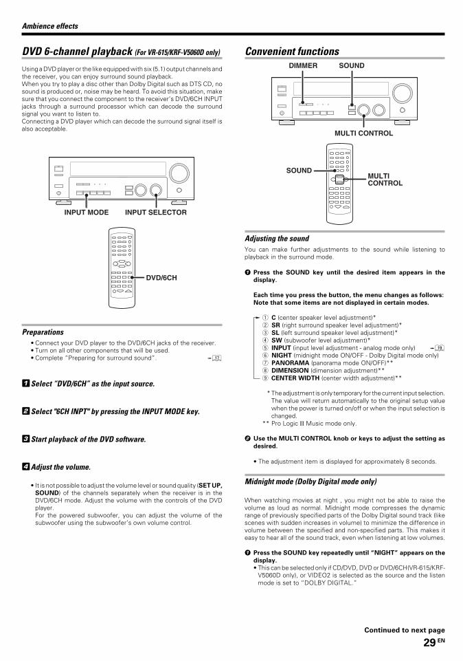
29 EN
DVD 6-channel playback (For VR-615/KRF-V5060D only)
Using a DVD player or the like equipped with six (5.1) output channels andthe receiver, you can enjoy surround sound playback.When you try to play a disc other than Dolby Digital such as DTS CD, nosound is produced or, noise may be heard. To avoid this situation, makesure that you connect the component to the receiver’s DVD/6CH INPUTjacks through a surround processor which can decode the surroundsignal you want to listen to.Connecting a DVD player which can decode the surround signal itself isalso acceptable.
DVD/6CH
INPUT SELECTORINPUT MODE
Preparations• Connect your DVD player to the DVD/6CH jacks of the receiver.• Turn on all other components that will be used.• Complete “Preparing for surround sound”. &
1Select “DVD/6CH” as the input source.
2Select "6CH INPT" by pressing the INPUT MODE key.
3Start playback of the DVD software.
4Adjust the volume.
• It is not possible to adjust the volume level or sound quality (SET UP,
SOUND) of the channels separately when the receiver is in theDVD/6CH mode. Adjust the volume with the controls of the DVDplayer.For the powered subwoofer, you can adjust the volume of thesubwoofer using the subwoofer’s own volume control.
Convenient functions
Adjusting the soundYou can make further adjustments to the sound while listening toplayback in the surround mode.
1 Press the SOUND key until the desired item appears in the
display.
Each time you press the button, the menu changes as follows:
Note that some items are not displayed in certain modes.
1 C (center speaker level adjustment)*2 SR (right surround speaker level adjustment)*3 SL (left surround speaker level adjustment)*4 SW (subwoofer level adjustment)*5 INPUT (input level adjustment - analog mode only) (6 NIGHT (midnight mode ON/OFF - Dolby Digital mode only)7 PANORAMA (panorama mode ON/OFF)**8 DIMENSION (dimension adjustment)**9 CENTER WIDTH (center width adjustment)**
* The adjustment is only temporary for the current input selection.The value will return automatically to the original setup valuewhen the power is turned on/off or when the input selection ischanged.
** Pro Logic II Music mode only.
2 Use the MULTI CONTROL knob or keys to adjust the setting as
desired.
• The adjustment item is displayed for approximately 8 seconds.
Midnight mode (Dolby Digital mode only)
When watching movies at night , you might not be able to raise thevolume as loud as normal. Midnight mode compresses the dynamicrange of previously specified parts of the Dolby Digital sound track (likescenes with sudden increases in volume) to minimize the difference involume between the specified and non-specified parts. This makes iteasy to hear all of the sound track, even when listening at low volumes.
1 Press the SOUND key repeatedly until “NIGHT” appears on the
display.
• This can be selected only if CD/DVD, DVD or DVD/6CH(VR-615/KRF-V5060D only), or VIDEO2 is selected as the source and the listenmode is set to “DOLBY DIGITAL.”
MULTI CONTROL
DIMMER SOUND
SOUNDMULTI CONTROL
Ambience effects
Continued to next page
*5197/26-30/EN 26/03/2002, 2:56 PM29
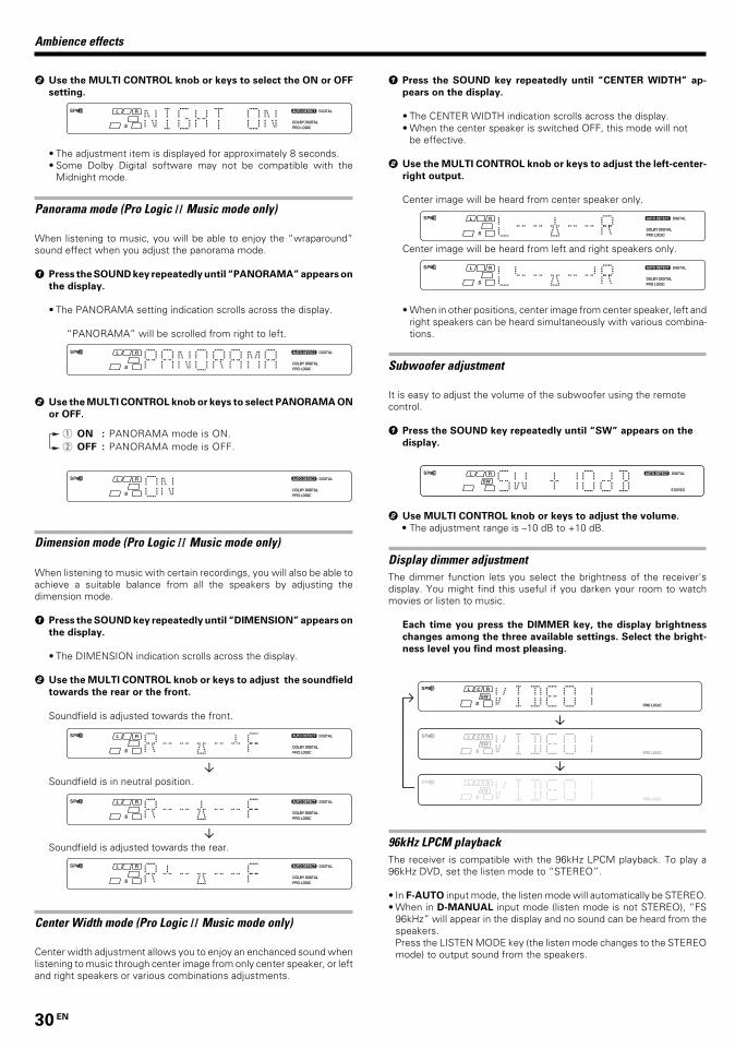
30 EN
2 Use the MULTI CONTROL knob or keys to select the ON or OFF
setting.
• The adjustment item is displayed for approximately 8 seconds.• Some Dolby Digital software may not be compatible with the
Midnight mode.
Panorama mode (Pro Logic II Music mode only)
When listening to music, you will be able to enjoy the “wraparound”sound effect when you adjust the panorama mode.
1 Press the SOUND key repeatedly until “PANORAMA” appears on
the display.
• The PANORAMA setting indication scrolls across the display.
“PANORAMA” will be scrolled from right to left.
2 Use the MULTI CONTROL knob or keys to select PANORAMA ON
or OFF.
1 ON : PANORAMA mode is ON.2 OFF : PANORAMA mode is OFF.
Dimension mode (Pro Logic II Music mode only)
When listening to music with certain recordings, you will also be able toachieve a suitable balance from all the speakers by adjusting thedimension mode.
1 Press the SOUND key repeatedly until “DIMENSION” appears on
the display.
• The DIMENSION indication scrolls across the display.
2 Use the MULTI CONTROL knob or keys to adjust the soundfield
towards the rear or the front.
Soundfield is adjusted towards the front.
Soundfield is in neutral position.
Soundfield is adjusted towards the rear.
Center Width mode (Pro Logic II Music mode only)
Center width adjustment allows you to enjoy an enchanced sound whenlistening to music through center image from only center speaker, or leftand right speakers or various combinations adjustments.
1 Press the SOUND key repeatedly until “CENTER WIDTH” ap-
pears on the display.
• The CENTER WIDTH indication scrolls across the display.• When the center speaker is switched OFF, this mode will not
be effective.
2 Use the MULTI CONTROL knob or keys to adjust the left-center-
right output.
Center image will be heard from center speaker only.
Center image will be heard from left and right speakers only.
• When in other positions, center image from center speaker, left andright speakers can be heard simultaneously with various combina-tions.
Subwoofer adjustment
It is easy to adjust the volume of the subwoofer using the remotecontrol.
1 Press the SOUND key repeatedly until “SW” appears on the
display.
2 Use MULTI CONTROL knob or keys to adjust the volume.
• The adjustment range is –10 dB to +10 dB.
Display dimmer adjustmentThe dimmer function lets you select the brightness of the receiver'sdisplay. You might find this useful if you darken your room to watchmovies or listen to music.
Each time you press the DIMMER key, the display brightness
changes among the three available settings. Select the bright-
ness level you find most pleasing.
96kHz LPCM playbackThe receiver is compatible with the 96kHz LPCM playback. To play a96kHz DVD, set the listen mode to “STEREO”.
• In F-AUTO input mode, the listen mode will automatically be STEREO.• When in D-MANUAL input mode (listen mode is not STEREO), “FS
96kHz” will appear in the display and no sound can be heard from thespeakers.Press the LISTEN MODE key (the listen mode changes to the STEREOmode) to output sound from the speakers.
Ambience effects
*5197/26-30/EN 26/03/2002, 2:56 PM30

31 EN
DVD player operation keysThe remote control of this unit can control two groups of KENWOOD DVD players directly without using the remote control supplied with the DVD player.
Group-1 : DV-4900, DV-4070B, DV-2070, DV-203, DVF-9010, DVF-K7010, DVF-5010, DVF-R9030, DVF-R7030, DVF-3530, DV-402, DV-5900,DV5700, DVF-R9050, DVF-J6050, DV-505, DV-503, DV-502, DVF-3550, DVF-3050 and DVF-R4050.
Group-2 : DV-4050, DV-303, DVF-R6030, DVF-K5020, DVF-5020, DVF-3020 and DVF-3030
Depending on your KENWOOD DVD model, you need to set up your receiver remote control as follows:
To set for Group-1 DVD players:
Press the numeric “1” key while pressing the “POWER ” key (not the DVD Power key) on your remote control.To set for Group-2 DVD players:
Press the numeric “2” key while pressing the “POWER ” key (not the DVD Power key) on your remote control.• If your DVD player is not listed in the list above, perform the set up for either Group-1 or Group-2. When the set up is successful, then your DVD
player falls into that particular group.
How to operate the DVD player with the remote control
1. Pressing the DVD Power key for more than 2 seconds turns the DVD player on or off.2. To carry out the functions of the DVD player, first press the DVD Power key, then press each key for each operation as explained in the DVD
operation pages in the operating instructions. In this case, the DVD operation mode is retained for 15 seconds after pressing any of those DVDoperation buttons.(To turn the receiver operation mode within 15 seconds, press the RECEIVER key.)
DVD player operation keys
You can perform these basic operations using the keys described below when connected to KENWOOD DVD player.
RETURN
TOP MENU(Title)
DOWN-PAGE-UP(Page up or down)
1 (Search)¡ (Search)
1
DISC SKIPBASS BOOSTAUTO
AUX CD/DVD
DVD
TUNER MD/TAPE
VIDEO1 VIDEO2
2 3
POWER
DVD
POWER
RECEIVER
MENU
P.CALL
TUNING
MUTE VOLUME
A/B+100
ENTER BAND
P.CALL
MULTI CONTROL
4 5 6
7 8 9
0 +10
SET UP
OSD
SOUND
RETURN
LISTEN MODE
DVD
DISC SEL.CINEMA EQ
LOUDNESSTOP MENU
TONE(For RC-R0622 only)
PHONO(For RC-R0620/R0622 only)
DVD/6CH
DOWN-PAGE-UP
RDS DISPLAY
(For RC-R0622/R0623 only)
PTY
Numeric keys(Select tracks)
7 (Stop)
6 (3 Play)8 (Pause)
ENTER (Enter)
MENU
OSD (OSD menu)
%(Cursor »)fi(Cursor «)#(Cursor \)@(Cursor |)
DVD POWERPOWER
RECEIVER(Receiver mode)
Basic remote control operations for other components
*5197/31-36/EN 26/03/2002, 2:58 PM31

32 EN
CASSETTE deck, CD player & MD recorder operationsYou can perform these basic operations using the keys described below when connected to KENWOOD cassette deck, MD recorder or CD playerequipped with system control operations. %
Cassette deck operations’ keys CD player operations’ keys
1
DISC SKIPBASS BOOSTAUTO
AUX CD/DVD
DVD
TUNER MD/TAPE
VIDEO1 VIDEO2
2 3
POWER
DVD
POWER
RECEIVER
MENU
P.CALL
TUNING
MUTE VOLUME
A/B+100
ENTER BAND
P.CALL
MULTI CONTROL
4 5 6
7 8 9
0 +10
SET UP
OSD
SOUND
RETURN
LISTEN MODE
DVD
DISC SEL.CINEMA EQ
LOUDNESS
DOWN-PAGE-UP
TOP MENU
TONE
6 (3 Play)
7 (Stop)
1 (Rewind)¡ (Fast forward)
A/B (Cassettedeck selection)
2 (Reverse play)
(For RC-R0620/R0622 only)
DVD/6CH
(For RC-R0622 only)
PHONO
RDS DISPLAY
(For RC-R0622/R0623 only)
PTY
1
DISC SKIPBASS BOOSTAUTO
AUX CD/DVD
DVD
TUNER MD/TAPE
VIDEO1 VIDEO2
2 3
POWER
DVD
POWER
RECEIVER
MENU
P.CALL
TUNING
MUTE VOLUME
A/B+100
ENTER BAND
P.CALL
MULTI CONTROL
4 5 6
7 8 9
0 +10
SET UP
OSD
SOUND
RETURN
LISTEN MODE
DVD
DISC SEL.CINEMA EQ
LOUDNESSTOP MENU
TONE
DOWN-PAGE-UP
Numeric keys(Select tracks)
6 (Play/Pause)
¢ (Skip up)
DISC SKIP
1 (Search)¡ (Search)
4 (Skip down)
7 (Stop)
(For RC-R0620/R0622 only)
DVD/6CH
(For RC-R0622 only)
PHONO
RDS DISPLAY
(For RC-R0622/R0623 only)
PTY
MD recorder operations’ keys
1
DISC SKIPBASS BOOSTAUTO
AUX CD/DVD
DVD
TUNER MD/TAPE
VIDEO1 VIDEO2
2 3
POWER
DVD
POWER
RECEIVER
MENU
P.CALL
TUNING
MUTE VOLUME
A/B+100
ENTER BAND
P.CALL
MULTI CONTROL
4 5 6
7 8 9
0 +10
SET UP
OSD
SOUND
RETURN
LISTEN MODE
DVD
DISC SEL.CINEMA EQ
LOUDNESSTOP MENU
TONE
+100 (Select tracks)
Numeric keys(Select tracks)
6 (3 Play)
¢ (Skip up)
1 (Search)¡ (Search)
4 (Skip down)
7 (Stop)
DOWN-PAGE-UP
(For RC-R0620/R0622 only)
DVD/6CH
(For RC-R0622 only)
PHONO
RDS DISPLAY
(For RC-R0622/R0623 only)
PTY
Notes1. Certain codes may only operate some of the function available on a given model.2. The charts above show the typical functions available for each component. Some manufacturers use different key combinations to perform similar
functions. For that reason, we have programmed extra functions on some of the unused number keys to help you control your equipment.
Basic remote control operations for other components
*5197/31-36/EN 26/03/2002, 2:58 PM32

33 EN
Amplifier
Cause
• The speaker cords are disconnected.
• VOLUME is set to the minimum position.• MUTE is ON.• The SPEAKERS switches are set to OFF.
• Speaker cords are short-circuited.
• The speaker cord is disconnected.
• The surround speaker cords and/or the centerspeaker cord is disconnected.
• A surround mode has not been engaged.• The surround and/or center volume controls
are set to the minimum level.
• The audio cord from the record player is notconnected to the PHONO jacks.
• The record player is not grounded.
• There are many possible causes for this prob-lem, depending on the type of DVD playerused.
• The input mode is set to digital manual.
• The software is copy-guarded.
Remedy
• Connect them properly referring to “Connect-ing the speakers” #
• Adjust the volume to a proper level.• Turn OFF the MUTE. )• Set the SPEAKERS switch to ON. (
• Turn the power off, eliminate the short-circuit-ing, then turn on the power again.
• Connect it properly referring to “Connectingthe speakers”. #
• Connect it properly referring to “Connectingthe speakers”. #
• Select a surround mode.• Adjust the speaker levels using the test tone.
*
• Insert the audio cord plugs securely into thePHONO jacks.
• Connect the grounding wire to the GND termi-nal on the rear panel.
• Set the input mode to digital manual beforestarting playback of the Dolby Digital source.
8
• Press the INPUT MODE key to select to digitalauto mode. 8
• Copy-guarded video software cannot be re-corded.
Symptom
No sound from the speakers.
The standby indicator blinks and sound is
not output.
Sound is not output from one of the speak-
ers.
Sound is not output from the surround
speakers and / or the center speaker, or their
sound is very small.
A humming noise is generated when the
PHONO input selector is selected.
When playing a Dolby Digital source signal
using a DVD player, the sound is cut off soon
after it starts.
No sound is produced during playback from
a DVD player.
A video source cannot be recorded normally.
In case of difficulty
Resetting the MicrocomputerThe microcomputer may malfunction (unit cannot be operated,
or shows an erroneous display) if the power cord is unplugged
while the power is ON, or due to some other external factor. If
this happens, execute the following procedure to reset the
microcomputer and return the unit to its normal operating
condition.
• Please note that resetting the microcomputer will clear the contentsof the memory and return the unit to the state it was in when it leftthe factory
Unplug the power cord from the wall outlet, then
plug it back in while holding down the POWER key.
For the U.S.A. and Canada
With the power cord plugged in, turn the POWER key
OFF. Then, while holding down the ON/STANDBY
key, press POWER.
For other countries
Tuner
Cause
• No antenna is connected.• The broadcast band is not set properly.• The frequency of the desired station is not
tuned.
• Noise due to ignition noise from an automo-bile.
• Noise due to interference from an electricappliance.
• Noise due to a nearby TV set.
• The preset station belongs to a frequency thatcannot be received.
• The preset memory was cleared because thepower cord had been unplugged for a longperiod of time.
Remedy
• Connect an antenna. $• Set the broadcast band properly.• Tune the frequency of the desired station.
™
• Install the outdoor antenna away from theroad.
• Turn off the power to the appliance.
• Install the receiver farther away from the TV.
• Preset a station with a receivable frequency.
• Preset the station again.
Symptom
Radio stations cannot be received.
Interference.
A station which was preset cannot be re-
ceived by pressing the corresponding nu-
meric key.
*5197/31-36/EN 26/03/2002, 2:58 PM33

34 EN
In case of difficulty
Remote control unit
Cause
• The remote control is set to a different opera-tion mode.
• Batteries are exhausted.• The remote control unit is too far away from
the main system, controlling angle is too large,or there is an obstacle between the receiverand the remote.
• The audio cords and system control cords arenot connected properly.
• No software is loaded in the source compo-nent.
• An attempt is made to play a tape which isbeing recorded in the cassette deck.
Remedy
• Press the source select keys or DVD POWER
keys to select the appropriate operation mode.• Replace with new batteries.• Operate the remote control unit within the
controllable range.
• Connect properly referring to “Setting up thesystem”.
• Place software in the source component youwant to play.
• Wait until recording has completed.
Symptom
Remote control operation is not possible.
*5197/31-36/EN 26/03/2002, 2:58 PM34

35 EN
Specifications Caution : Read this page carefully to ensure safe
operation.
For the U.S.A and CanadaAUDIO section (VR-605/615)Rated power output during STEREO operation
Effective power output during SURROUND operationFRONT (40 ~ 20 kHz, 0.7% T.H.D. at 8Ω one channel driven)............................................................................... 100 W + 100 W
CENTER (40 ~ 20 kHz, 0.7% T.H.D. at 8Ω one channel driven).............................................................................................. 100 W
SURROUND (40 ~ 20 kHz, 0.7% T.H.D. at 8Ω one channeldriven) ................................................................... 100 W + 100 WSUBWOOFER (80 Hz, 0.7% T.H.D. at 8Ω one channel driven)(VR-615) ................................................................................ 100 W
Total harmonic distortion ........................... 0.05% (1 kHz, 50 W, 8Ω)Frequency response
CD ............................................... 20 Hz ~ 70 kHz, +0 dB, –3.0 dBSignal to noise ratio (IHF’66)
CD .......................................................................................... 95 dBInput sensitivity / impedance
CD ......................................................................... 550 mV / 47 kΩDVD/6CH INPUT (VR-615) .................................. 550 mV / 47 kΩ
Output level / impedanceTAPE REC ............................................................... 550 mV / 1 kΩPRE OUT (SUBWOOFER) (VR-605) ...................... 1.5 V / 2.2 kΩ
Tone controlBASS................................................................ ±10 dB (at 100 Hz)TREBLE ............................................................ ±10 dB (at 10 kHz)
Loudness controlVOLUME at -30dB level ................................... +8 dB (at 100 Hz)
For other countriesAUDIO section (KRF-V5060D/V5560D)Rated power output during STEREO operation
Effective power output during SURROUND operationFRONT (1 kHz, 0.7% T.H.D. at 8Ω one channel driven)............................................................................... 100 W + 100 W
CENTER (1 kHz, 0.7% T.H.D. at 8Ω one channel driven).............................................................................................. 100 W
SURROUND (1 kHz, 0.7% T.H.D. at 8Ω one channel driven)............................................................................... 100 W + 100 W
SUBWOOFER (80 Hz, 0.7% T.H.D. at 8Ω one channel driven)(KRF-V5560D) ...................................................................... 100 W
Total harmonic distortion ........................... 0.05% (1 kHz, 50 W, 8Ω)Frequency response
CD ............................................... 20 Hz ~ 70 kHz, +0 dB, –3.0 dBSignal to noise ratio (IHF’66)
CD, TUNER, AUX, TAPE ...................................................... 95 dBInput sensitivity / impedance
CD ......................................................................... 550 mV / 47 kΩDVD/6CH INPUT (KRF-V5060D) ........................ 550 mV / 10 kΩ
Output level / impedanceTAPE REC ............................................................... 550 mV / 1 kΩPRE OUT (SUBWOOFER) (KRF-V5060D) ............. 1.5 V / 2.2 kΩ
Tone controlBASS................................................................ ±10 dB (at 100 Hz)TREBLE ............................................................ ±10 dB (at 10 kHz)
Loudness controlVOLUME at -30dB level ................................... +8 dB (at 100 Hz)
AUDIO section (KRF-V4060D)Effective power output during STEREO operation
1 kHz, 0.7% T.H.D.,at 8 Ω ............................................. 50 W + 50 WRated power output during STEREO operation
Effective power output during SURROUND operationFRONT (1 kHz, 0.7% T.H.D. at 8Ω one channel driven)................................................................................... 50 W + 50 W
CENTER (1 kHz, 0.7% T.H.D. at 8Ω one channel driven)................................................................................................ 50 W
SURROUND (1 kHz, 0.7% T.H.D. at 8Ω one channel driven)................................................................................... 50 W + 50 W
Total harmonic distortion ........................... 0.15% (1 kHz, 20 W, 8Ω)Frequency response
CD ............................................... 20 Hz ~ 70 kHz, +0 dB, –3.0 dBSignal to noise ratio (IHF’66)
CD, TUNER, AUX, TAPE ...................................................... 95 dBInput sensitivity / impedance
CD ......................................................................... 400 mV / 47 kΩOutput level / impedance
TAPE REC ............................................................... 400 mV / 1 kΩPRE OUT (SUBWOOFER) ...................................... 1.5 V / 2.2 kΩ
Tone controlBASS.................................................................. ±10 dB (at 70 Hz)TREBLE ............................................................ ±10 dB (at 10 kHz)
Loudness controlVOLUME at -30dB level ................................... +8 dB (at 100 Hz)
DIGITAL AUDIO sectionSampling frequency ...................... 32 kHz, 44.1 kHz, 48 kHz, 96 kHzInput level / impedance / wave length
Optical ........................... (–15 dBm ~ –21 dBm), 660 nm ±30 nmCoaxial ................................................................... 0.5 Vp-p / 75 Ω
VIDEO sectionVIDEO inputs / outputs
VIDEO (composite) ................................................. 1 Vp-p / 75 Ω
FM tuner sectionTuning frequency range................................. 87.5 MHz ~ 108.0 MHzUsable sensitivity (MONO)
VR-605/615.................1.3 µV (75 Ω)/ 13.2 dBf (75 kHz DEV., SINAD 30 dB)
KRF-V5060D/V4060D/V5560D................... 1.6 µV (75 Ω)/ 15.2 dBf (75 kHz DEV., SINAD 30 dB)
50dB quieting sensitivitySTEREO ..................................................... 28 µV (75 Ω)/ 40.2 dBf
Total harmonic distortion (1 kHz)MONO.......................................................... 0.5% (71.2 dBf input)STEREO ....................................................... 0.7% (71.2 dBf input)
Signal to noise ratio (1 kHz, 75 kHz DEV.)MONO........................................................ 75 dB (71.2 dBf input)STEREO ..................................................... 68 dB (71.2 dBf input)
Stereo separation (1 kHz) ........................................................... 40 dBSelectivity (±400 kHz) VR-605/615 ............................................ 70 dB KRF-V5060D/V4060D/V5560D ............. 50 dB
Frequency response .................... (30 Hz ~ 15kHz), +0.5 dB, –3.0 dB
AM tuner sectionTuning frequency range
10 kHz step (VR-605/615) ........................... 530 kHz ~ 1,700 kHz10 kHz step (KRF-V5060D/V4060D/V5560D) .................................................................................................... 530 kHz ~ 1,610 kHz
9 kHz step (KRF-V5060D/V4060D/V5560D) ...................................................................................................... 531 kHz ~ 1,602 kHz
Usable sensitivity (30% mod., S/N 20dB) (VR-606/615)........................................................................ 16 µV / (600 µV/m)
Usable sensitivity (KRF-V5060D/V5560D/V4060D) ................................................................................................... 16 µV / (600 µV/m)
Signal to noise ratio (30% mod. 1 mV input) ........................... 50 dB
GENERALPower consumption VR-605/615 ................................................ 2.2 A
KRF-V5060D/V5560D .............................. 280WKRF-V4060D ............................................. 200W
AC outletSWITCHEDVR-605/615 ........................................ (total 150 W, 1.25 A max.)KRF-V5060D/V4060D/V5560D ....................... (total 90 W max.)
Dimensions .................................................... W : . 440 mm (17-5/16")H : 143 mm (5-5/8")D : 303 mm (11-15/16")
Weight (Net)VR-605/615 ......................................................... 7.7 kg (17.00 lb)KRF-V5060D/V5560D ......................................... 8.8 kg (19.40 lb)KRF-V4060D ........................................................ 7.9 kg (17.41 lb)
100 watts per channel minimum RMS, both channels driven, at 8Ω from40 Hz to 20 kHz with no more than 0.7% total harmonic distortion. (FTC)
100 watts per channel minimum RMS, both channels driven, at 8Ω from40 Hz to 20 kHz with no more than 0.7% total harmonic distortion. (FTC)
40 watts per channel minimum RMS, both channels driven, at 8Ω from40 Hz to 20 kHz with no more than 0.7% total harmonic distortion. (FTC)
*5197/31-36/EN 26/03/2002, 2:58 PM35

36 EN
Specifications
Notes1. KENWOOD follows a policy of continuous advancements in development. For this reason specifications may be changed without notice.2. The full performance may not be exhibited in an extremely cold location (under a water-freezing temperature).
For your recordsRecord the serial number, found on the back of the unit, in the spacesdesignated on the warranty card, and in the space provided below. Referto the model and serial numbers whenever you call upon your dealer forinformation or service on this product.
Model_____________________ Serial Number_____________________
For the U.K and EuropeAUDIO section (KRF-V5060D)Rated power output during STEREO operation
DIN/IEC (63 Hz ~ 12.5 kHz, 0.7% T.H.D., at 6Ω)............................................................................... 100 W + 100 W
Effective power output during SURROUND operationFRONT (1 kHz, 0.7% T.H.D. at 6Ω one channel driven)............................................................................... 100 W + 100 W
CENTER (1 kHz, 0.7% T.H.D. at 6Ω one channel driven).............................................................................................. 100 W
SURROUND (1 kHz, 0.7% T.H.D. at 6Ω one channel driven)............................................................................... 100 W + 100 W
Total harmonic distortion ............................ 0.05% (1kHz, 50 W, 6Ω)Frequency response (IHF’66)
CD ............................................... 20 Hz ~ 70 kHz, +0 dB, –3.0 dBSignal to noise ratio (IHF’66)
PHONO (MM) ........................................................................ 74 dBCD .......................................................................................... 95 dB
Input sensitivity / impedancePHONO (MM) ........................................................ 6.0 mV / 27 kΩCD ......................................................................... 500 mV / 47 kΩDVD/6CH INPUT.................................................. 500 mV / 47 kΩ
Output level / impedanceTAPE REC ............................................................... 500 mV / 1 kΩPRE OUT (SUBWOOFER) ...................................... 1.5 V / 2.2 kΩ
Tone controlBASS................................................................ ±10 dB (at 100 Hz)TREBLE ............................................................ ±10 dB (at 10 kHz)
Loudness controlVOLUME at -30dB level ................................... +8 dB (at 100 Hz)
AUDIO section (KRF-V4060D)Rated power output during STEREO operation
(DIN 1 kHz 0.7% T.H.D., at 6Ω) ............................... 50 W + 50 WEffective power output during SURROUND operation
FRONT (1 kHz, 0.7% T.H.D. at 6Ω one channel driven)................................................................................... 50 W + 50 W
CENTER (1 kHz, 0.7% T.H.D. at 6Ω one channel driven)................................................................................................ 50 W
SURROUND (1 kHz, 0.7% T.H.D. at 6Ω one channel driven)................................................................................... 50 W + 50 W
Total harmonic distortion ........................... 0.15% (1 kHz, 20 W, 6Ω)Frequency response (IHF’66)
CD ............................................... 20 Hz ~ 70 kHz, +0 dB, –3.0 dBSignal to noise ratio (IHF’66)
CD .......................................................................................... 95 dBInput sensitivity / impedance
CD ......................................................................... 400 mV / 47 kΩOutput level / impedance
TAPE REC ............................................................... 400 mV / 1 kΩPRE OUT (SUBWOOFER) ...................................... 1.5 V / 2.2 kΩ
Tone controlBASS................................................................ ±10 dB (at 100 Hz)TREBLE ............................................................ ±10 dB (at 10 kHz)
Loudness controlVOLUME at -30dB level ................................... +8 dB (at 100 Hz)
DIGITAL AUDIO sectionSampling frequency ....................... 32 kHz, 44.1 kHz, 48 kHz, 96kHzInput level / impedance / wave length
Optical ............................ (–15 dBm ~ –21 dBm), 660 nm ±30nmCoaxial ................................................................... 0.5 Vp-p / 75 Ω
VIDEO sectionVIDEO inputs / outputs
VIDEO (composite) ................................................. 1 Vp-p / 75 Ω
FM tuner sectionTuning frequency range................................. 87.5 MHz ~ 108.0 MHz
Usable sensitivity (DIN at 75 Ω)MONO..................... 1.3 µV / 13.2 dBf (40 kHz DEV., S/N 26 dB)STEREO ................... 45 µV / 42.1 dBf (46 kHz DEV., S/N 46 dB)
Total harmonic distortion (1 kHz)MONO.......................................................... 0.2% (71.2 dBf input)STEREO ....................................................... 0.8% (71.2 dBf input)
Signal to noise ratio (DIN weighted)MONO.................................. 65 dB (40 kHz DEV. 71.2 dBf input)STEREO ............................... 60 dB (46 kHz DEV. 71.2 dBf input)
Stereo separation (DIN 1 kHz) ................................................... 36 dBSelectivity (DIN ±300 kHz) .......................................................... 64 dBFrequency response ................... (30 Hz ~ 15 kHz), +0.5 dB, –3.0 dB
AM tuner sectionTuning frequency range..................................... 531 kHz ~ 1,602 kHzUsable sensitivity ................................................. 16 µV / (600 µV/m)Signal to noise ratio (30% mod. 1 mV input) ........................... 50 dB
GENERALPower consumption
KRF-V5060D .......................................................................... 280WKRF-V4060D .......................................................................... 200W
AC outletSWITCHED ....................................................... (total 90 W max.)
Dimensions ........................................................................ W : 440 mmH : 143 mmD : 303 mm
Weight (Net) ................................................................................ 7.8 kg
*5197/31-36/EN 26/03/2002, 2:58 PM36