voyager old school user manual - moog music
TRANSCRIPT
Page 3
Table of Contents
FORWARD from Mike Adams .................................. 4
THE BASICSHow to use this Manual ....................................... 5Setup and Connections ........................................ 6Overview and Features ........................................ 8Signal Flow .................................................................... 10
THE COMPONENTSA. Mixer Section ........................................................ 13B. Oscillator Section ................................................ 15C. Filter Section ......................................................... 18D. Envelopes Section .............................................. 21E. Output Section ..................................................... 24F. Modulation Section .......................................... 25G. LFO Section ......................................................... 28H. Keyboard & LH Controllers ......................... 30I. Back Panel .................................................................. 31
APPENDICESA – Specifi cations ................................................................. 33B – VX-351 CV Expander .............................................. 34C – Using the CP-251 with the Voyager ................. 41D – Synthesis Tutorial ......................................................... 44E – Service & Support Information ........................... 49F – Caring for the Voyager Old School ................... 49G – Accessories ................................................................... 50
GLOSSARY ....................................................................................... 52PATCH TEMPLATES ..................................................................... 56
User’s ManualVoyager Old School

Page 4
Page 5
Voyager OS User’s Manual - The Basics
Congratulations! You now own the Minimoog Voyager Old School, a successor to the synthesizer that Sonic State named the number one synth of all time: the Minimoog Model D. A descendant of the original Minimoog, the Voyager Old School is an ‘instant classic’ that is destined to become another revered piece of synthesizer history, and it is truly yours!
We are so pleased to bring this product to you, and expect it to give you a lifetime of musical satisfaction. Of course, all of the credit goes to Bob Moog, to whose specifi cations we still build instruments everyday. The release of the Voyager Old School synthesizer pays homage to Bob as well as to the classic Model D Minimoog. The Old School has the analog sound engine of the original Voyager, but without the digital elements of patch storage and MIDI control. It recaptures the directness and simplicity of the Model D, but adds extended modulation and Control Voltage interface capabilities. If you are a long time Minimoog player or have always wanted an original Model D, the Voyager Old School is the perfect solution for you. For those looking for a full-featured centerpiece for their modular synth rig or for anyone craving a direct, hands-on connection to their musical creativity, I believe you will fi nd all of that and more with this exciting new product.
Before you power up and start exploring your new Voyager Old School, let me offer two brief reminders. First, please register your beautiful new instrument via the Moog Music web site www.moogmusic.com (alternatively you can mail in the included warranty card), and let us know what you think in the ‘Comments’ section. We value every response that comes to us through our warranty registration program. Second, start playing! And once you do, promise yourself you will go back and read this User’s Manual. It was created to give you a complete understanding of how the Voyager Old School operates and offers helpful suggestions for getting the most from the instrument.
Finally, thank you for sharing your hard earned dollars, euros, sterling, or rupiahs with us. We never take that for granted and we want to encourage you to contact us for any reason - hopefully it will be to simply say “I love this machine.”
And, if you are ever near Asheville, N.C. USA, please come by the Moog factory. We’d love to see you!
Warm Regards,
Mike AdamsPresident, Moog Music, Inc.
Forward
Page 4
Page 5
Voyager OS User’s Manual - The Basics
This User’s Manual is organized into convenient sections to assist you in setting up, playing and exploring your new Voyager OS.
The Setup and Connections section explains how to unpack, setup and connect the Voyager OS, and provides a quick start to get you up and running with your new instrument.
The Components section offers detailed explanations of the Voyager OS components that create and modify sound.
The Appendix provides additional information, such as technical specifi cations, service and support info, and making connections to optional external equipment. First time users should read Appendix D, SynthesisTutorial, where you will fi nd an explanation of sound and subtractive synthesis.
At the back of the manual, you’ll fi nd a Glossary that defi nes important synthesizer terminology, and several Glossary that defi nes important synthesizer terminology, and several GlossaryPatch Template pages for programming and documenting your favorite sounds.
Icons
Throughout the manual you will see icons that offer additional information. Here’s what they mean:
This icon indicates an important note concerning the operation of the Voyager.
This icon indicates a useful performance or programming tip.
This icon indicates technical information for the advanced user or the technically curious.
How to Use this Manual
Page 6
Voyager OS User’s Manual - The Basics
Page 7
Voyager OS User’s Manual - The Basics
In a perfect world, everyone would read the User’s Manual from cover to cover before connecting and playing their new instrument. For those of you who don’t live in a perfect world and can’t wait to play your new synthesizer (completely understandable), the following should get you set up and running quickly.
Note: You are encouraged to read the entire manual at some point to learn more about the instrument and gain a better understanding of what you can do with the Voyager.
Check the contents in the shipping cartonThe Voyager is shipped with the following items:
1. The Voyager OS Synthesizer 2. Power cord 3. User’s Manual 4. Warranty registration card
What you will need In addition to the Voyager and provided accessories, you will need: 1. A stand or table suffi cient to support the Voyager OS 2. A 1⁄4” instrument cable (for mono) or two 1/4” instrument cables (for stereo) and an amplifi er, or a pair of headphones 3. A properly wired AC outlet.
Set upMake sure you have an adequate place to set it up. You will need a sturdy keyboard stand or fl at surface that will provide the proper support (the Voyager Old School weighs approximately 40 lbs.) and will not easily topple. Use caution when lifting the Voyager out of the carton, and be sure to save the carton and all packing material in case you need to ship the Voyager for any reason.
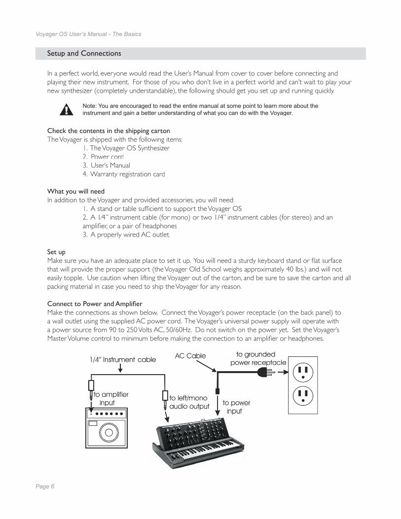
Connect to Power and Amplifi erMake the connections as shown below. Connect the Voyager’s power receptacle (on the back panel) to a wall outlet using the supplied AC power cord. The Voyager’s universal power supply will operate with a power source from 90 to 250 Volts AC, 50/60Hz. Do not switch on the power yet. Set the Voyager’s Master Volume control to minimum before making the connection to an amplifi er or headphones.
Setup and Connections
Page 6
Voyager OS User’s Manual - The Basics
Page 7
Voyager OS User’s Manual - The Basics
Now Power upTurn the Voyager OS power ON. The LFO RATE LED will be begin to blink at the rate set by LFO RATE knob, indicating that the Voyager OS is ON.
Test for Sound and Set LevelsPlay a few notes on the Voyager OS keyboard while turning up the volume of your amplifi cation. Set the volume to a comfortable listening level.
Start PlayingThe sound produced by the Voyager OS is determined by the various knob and switch settings on the front panel, along with the switches and controllers wheels in the left-hand controller section.
Creating SoundsTo create your own sounds from scratch, it’s best to start from a default patch confi guration. This will give you a familiar starting point and guaranty that sound will be produced. To set the Voyager OS to a default patch, adjust the knobs and switches according to the light blue/grey markings on the panel. This will give you a basic one-oscillator square wave sound that will act as a blank canvas for your sonic creations.
After you adjust the Voyager panel controls to the default settings, try the controls to the right of the Mixer, one at a time, starting with FILTER CUTOFF, and notice how they affect the sound. Then try combining different tones with the Mixer and Mixer and Mixer Oscillators 2 and 3. Finally experiment with the Mod Busses to see how different types of modulation affect the sound.
When working with the Voyager, keep in mind that many of the controls are interactive, so there is frequently more than one way to control a single parameter. This may be a source of confusion at fi rst. For instance, if the SUSTAIN control of the Volume Envelope is all the way down, and the ATTACK and DECAY knobs are set to zero, there will be no output. Similarly, if you have a sound where the AMOUNT TO FILTER knob for the Filter Envelope is set to zero, then changing the Filter Envelope ATTACK control will likely result in no audible change. To use your Voyager to its fullest potential, it is very important to understand the workings of all the controls and how they interact in order to understand how a sound (or lack thereof) is produced. Don’t get frustrated; simply work systematically until you know what each control does and how it works with the rest of the Voyager.
If you are new to subtractive synthesis, be sure to read the synthesis tutorial that appears in Appendix D.
Warranty registrationMoog’s on-line warranty registration system is the best way to activate your warranty. Access the Moog web site at www.moogmusic.com and click on the “Product Register” tab. If you complete all the requested information, Moog Music will send you a complimentary gift.
NOTE: The Voyager is recommended for an operating temperature between about 50 and 100 degrees Fahrenheit. It is safe to operate the synthesizer outside of this range (between 0 and 125 degrees F), but the Voyager’s voltage controlled oscilators (VCOs) may not remain in tune.
It is recommended that a warm up period of about 15 minutes be allowed before using the Voyager. The warm up period may be longer if the Voyager has been stored outside the recom-mended operating temperture range.

Page 8
Voyager OS User’s Manual - The Basics
Page 9
Voyager OS User’s Manual - The Basics
The Voyager OS is a monophonic analog performance synthesizer that is a successor to the classic Model D Minimoog. Its sound sources are three analog, variable waveform oscillators, a noise source, and an external audio input. Extensive modulation and fi ltering options give the Voyager OS an expansive sound palette.
Overview and Features

Page 8
Voyager OS User’s Manual - The Basics
Page 9
Voyager OS User’s Manual - The Basics
Back Panel:
The Voyager’s back panel offers con-nections for Power, Control Voltage (CV) and Gate I/O, and Audio I/O. There are 14 CV inputs and 2 CV out-puts provided on 1⁄4“ jacks. Jacks identi-fi ed with a red nut indicate a combina-tion CV/Expression Pedal input, while jacks identifi ed with a blue nut indicate a combination Gate/footswitch input.

Page 10
Voyager OS User’s Manual - The Basics
Page 11
Voyager OS User’s Manual - The Basics
To understand the signal fl ow of the Voyager OS, it’s helpful to consider the three types of signal rout-ings in the system: the audio path, the control voltage path, and the modulation path.
Audio Path
The Voyager’s audio path includes all of the signal sources and signal modifi ers that produce an audio output. These include the oscillators, mixer, fi lters and amplifi ers (VCAs).
The Oscillator section includes controls for selecting the octave and waveforms, adjusting the tuning of the second and third oscillators, for setting the oscillator sync and linear FM functions, and for setting the frequency range and keyboard control for Oscillator 3. The Mixer section is where the oscillators and other sound sources (noise and external input) are selected and mixed together. The output of the Mixer section is routed to the Filter section through a Mixer Out/Filter In jack on the Voyager’s rear panel. This jack allows you to interrupt the signal routing between the Mixer and Filter to insert an external effect, or take the output of the Mixer directly.
The Filter section is responsible for altering the harmonic content of the combined sound sources. The Voyager’s Filter section contains two fi lters that work together in two different modes.: Dual LP and HP/LP. Dual LP mode features two lowpass fi lters in parallel, while HP/LP (Highpass-Lowpass) mode features a lowpass and highpass fi lter in series, creating a Bandpass fi lter response. In either mode, the Filter Cutoff control affects the cutoff frequency of both fi lters, and the Spacing control is used to adjust the difference between the cutoff frequencies. The outputs of the fi lters are routed to the Voltage Controlled Amplifi ers (VCAs).
The VCAs shape the volume level of the audio signal using time-varying control signals called Envelopes. The Envelopes section (part of the control voltage path) contains one Envelope Generator to control the Filters, and one Envelope Generator to control the VCAs. The Voyager’s audio path is illustrated below.
Signal Flow
The Voyager OS Audio Path
Page 10
Voyager OS User’s Manual - The Basics
Page 11
Voyager OS User’s Manual - The Basics
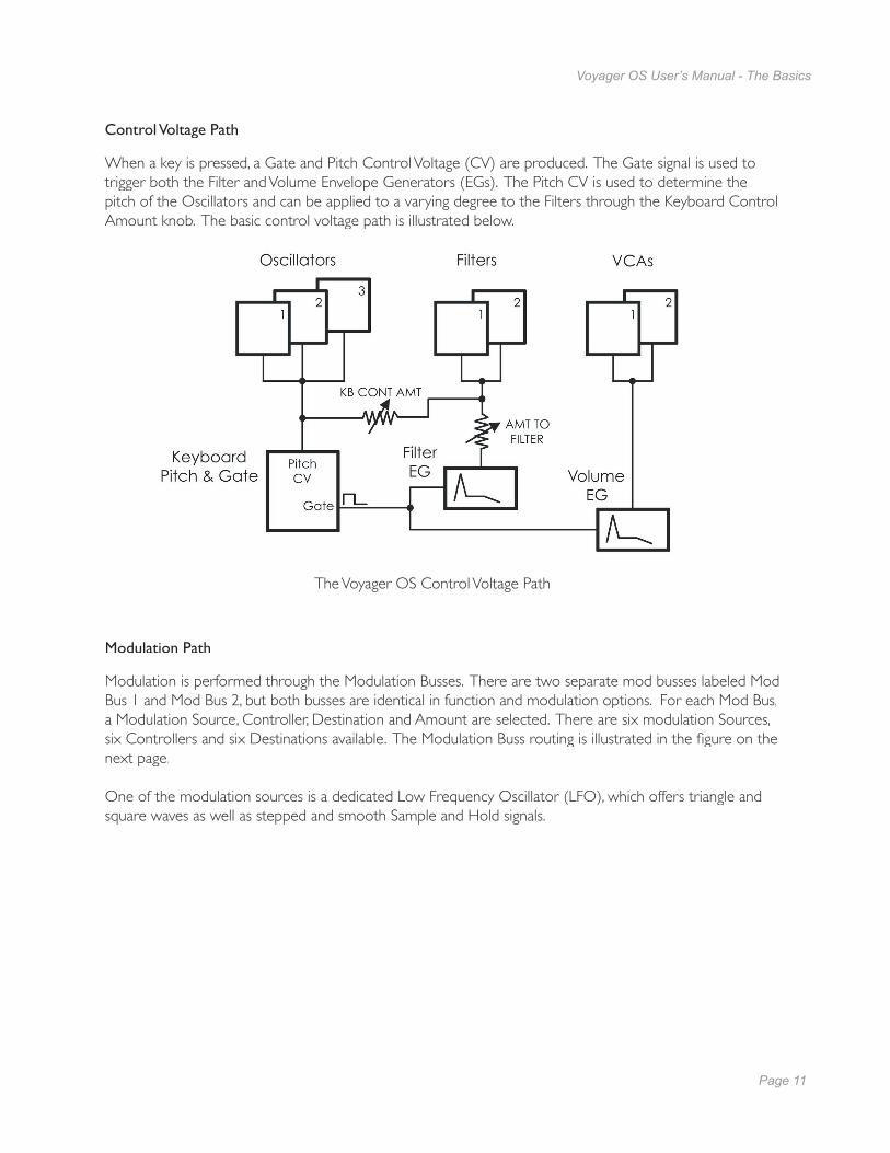
Control Voltage Path
When a key is pressed, a Gate and Pitch Control Voltage (CV) are produced. The Gate signal is used to trigger both the Filter and Volume Envelope Generators (EGs). The Pitch CV is used to determine the pitch of the Oscillators and can be applied to a varying degree to the Filters through the Keyboard Control Amount knob. The basic control voltage path is illustrated below.
Modulation Path
Modulation is performed through the Modulation Busses. There are two separate mod busses labeled Mod Bus 1 and Mod Bus 2, but both busses are identical in function and modulation options. For each Mod Bus, a Modulation Source, Controller, Destination and Amount are selected. There are six modulation Sources, six Controllers and six Destinations available. The Modulation Buss routing is illustrated in the fi gure on the next page.
One of the modulation sources is a dedicated Low Frequency Oscillator (LFO), which offers triangle and square waves as well as stepped and smooth Sample and Hold signals.
The Voyager OS Control Voltage Path

Page 12
Voyager OS User’s Manual - The Basics
Page 13
Voyager OS User’s Manual - The Components
The Voyager OS Modulation Buss
Page 12
Voyager OS User’s Manual - The Basics
Page 13
Voyager OS User’s Manual - The Components
Now let’s take a look at the individual module components that make up the Voyager OS Synthesizer, starting with the Mixer section. Then we’ll cover the Oscillators, Filters, Envelopes, and Output Sections, the LFO and Modulation sections, the Keyboard and Left-Hand controllers, and the Back Panel.
A. The Mixer Section
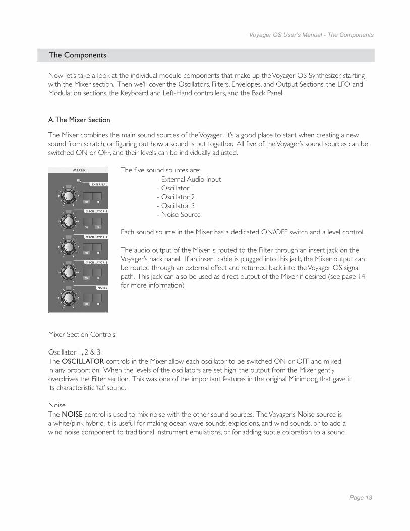
The Mixer combines the main sound sources of the Voyager. It’s a good place to start when creating a new sound from scratch, or fi guring out how a sound is put together. All fi ve of the Voyager’s sound sources can be switched ON or OFF, and their levels can be individually adjusted.
The fi ve sound sources are: - External Audio Input - Oscillator 1 - Oscillator 2 - Oscillator 3 - Noise Source
Each sound source in the Mixer has a dedicated ON/OFF switch and a level control.
The audio output of the Mixer is routed to the Filter through an insert jack on the Voyager’s back panel. If an insert cable is plugged into this jack, the Mixer output can be routed through an external effect and returned back into the Voyager OS signal path. This jack can also be used as direct output of the Mixer if desired (see page 14 for more information).
The Components
Mixer Section Controls:
Oscillator 1, 2 & 3: The OSCILLATOR controls in the Mixer allow each oscillator to be switched ON or OFF, and mixed in any proportion. When the levels of the oscillators are set high, the output from the Mixer gently overdrives the Filter section. This was one of the important features in the original Minimoog that gave it its characteristic ‘fat’ sound.
Noise: The NOISE control is used to mix noise with the other sound sources. The Voyager’s Noise source is a white/pink hybrid. It is useful for making ocean wave sounds, explosions, and wind sounds, or to add a wind noise component to traditional instrument emulations, or for adding subtle coloration to a sound.
Page 14
Voyager OS User’s Manual - The Components
Page 15
Voyager OS User’s Manual - The Components
External:The EXTERNAL control allows an external monophonic audio source to be routed into the Mixer, where it can be mixed with the Oscillators and Noise source (an “Ext Audio In” jack on the Voyager back panel is provided for this input). The LED above the EXTERNAL control knob begins to light up as the input signal overdrives the Mixer input. When the light is faint, a small amount of soft clipping is occurring. When the LED is bright, the signal is strongly overdriven. Judicious use of overdrive can really fatten up a sound. The External Audio Input can accept a signal from instrument level to line level.
Mixer Back Panel Connections:
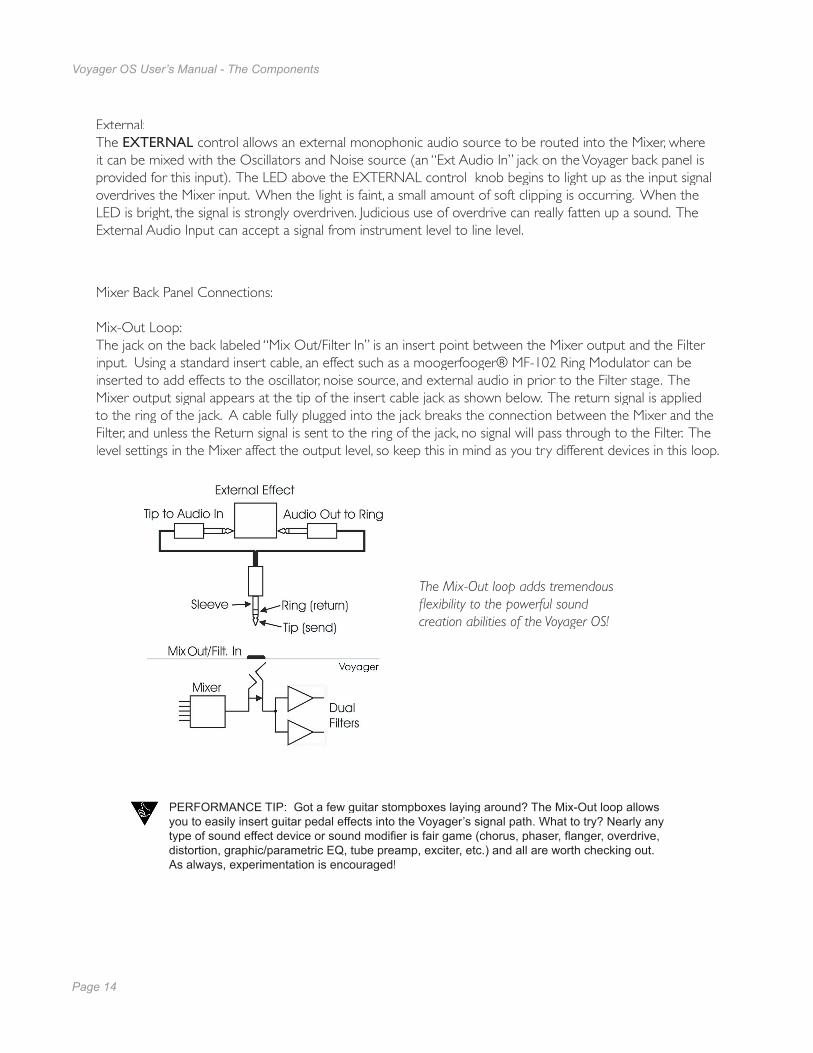
Mix-Out Loop: The jack on the back labeled “Mix Out/Filter In” is an insert point between the Mixer output and the Filter input. Using a standard insert cable, an effect such as a moogerfooger® MF-102 Ring Modulator can be inserted to add effects to the oscillator, noise source, and external audio in prior to the Filter stage. The Mixer output signal appears at the tip of the insert cable jack as shown below. The return signal is applied to the ring of the jack. A cable fully plugged into the jack breaks the connection between the Mixer and the Filter, and unless the Return signal is sent to the ring of the jack, no signal will pass through to the Filter. The level settings in the Mixer affect the output level, so keep this in mind as you try different devices in this loop.
PERFORMANCE TIP: Got a few guitar stompboxes laying around? The Mix-Out loop allows you to easily insert guitar pedal effects into the Voyager’s signal path. What to try? Nearly any type of sound effect device or sound modifi er is fair game (chorus, phaser, fl anger, overdrive, distortion, graphic/parametric EQ, tube preamp, exciter, etc.) and all are worth checking out. As always, experimentation is encouraged!
The Mix-Out loop adds tremendous fl exibility to the powerful sound creation abilities of the Voyager OS!
Page 14
Voyager OS User’s Manual - The Components
Page 15
Voyager OS User’s Manual - The Components
B. The Oscillator Section
The Oscillators are the main sound source of the Voyager. The oscillators in the Voyager are all analog Voltage Controlled Oscillators, or VCOs. They feature a temperature regulation circuit that provides them with excellent tuning stability. The VCOs can produce a total musical range of 8 1⁄2 octaves! In addition, the frequency of oscillator 3 can be set to the sub-audio range (<20Hz) for use as a second LFO.
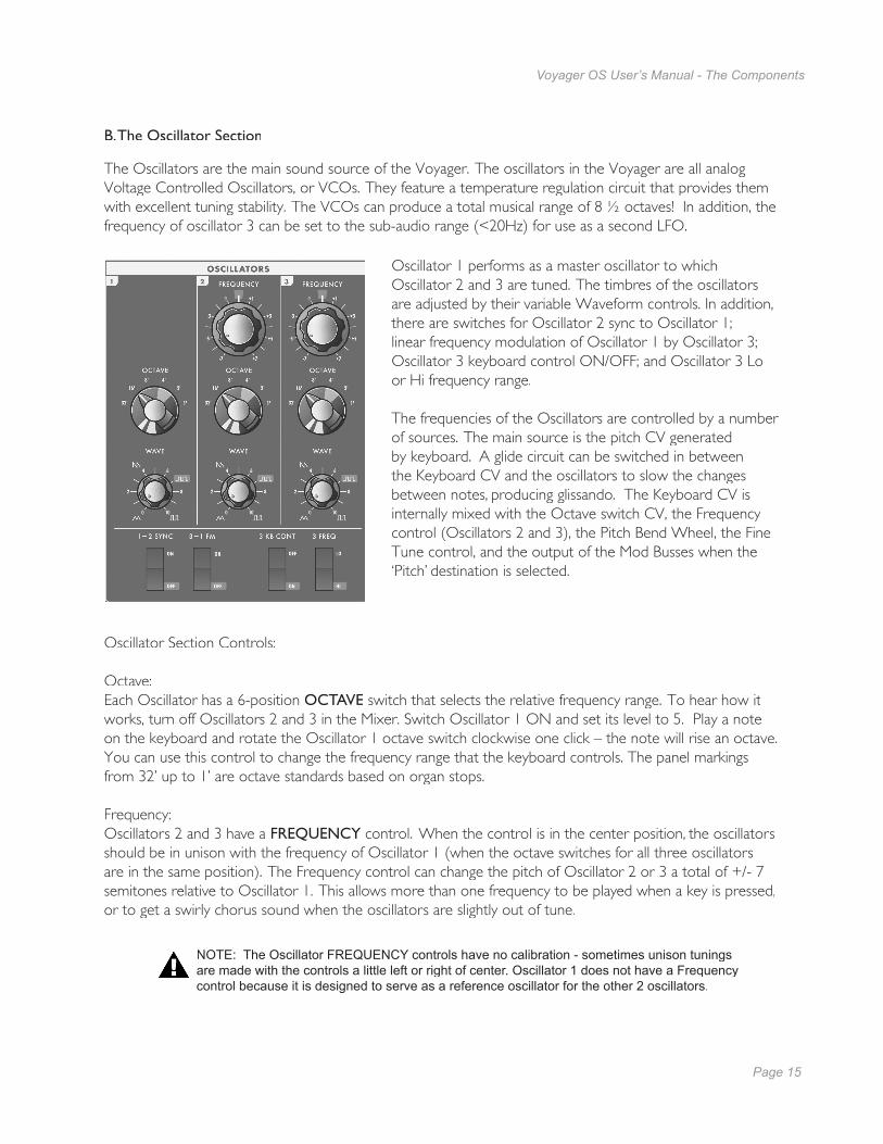
Oscillator 1 performs as a master oscillator to which Oscillator 2 and 3 are tuned. The timbres of the oscillators are adjusted by their variable Waveform controls. In addition, there are switches for Oscillator 2 sync to Oscillator 1; linear frequency modulation of Oscillator 1 by Oscillator 3; Oscillator 3 keyboard control ON/OFF; and Oscillator 3 Lo or Hi frequency range.
The frequencies of the Oscillators are controlled by a number of sources. The main source is the pitch CV generated by keyboard. A glide circuit can be switched in between the Keyboard CV and the oscillators to slow the changes between notes, producing glissando. The Keyboard CV is internally mixed with the Octave switch CV, the Frequency control (Oscillators 2 and 3), the Pitch Bend Wheel, the Fine Tune control, and the output of the Mod Busses when the ‘Pitch’ destination is selected.
Oscillator Section Controls:
Octave:Each Oscillator has a 6-position OCTAVE switch that selects the relative frequency range. To hear how it works, turn off Oscillators 2 and 3 in the Mixer. Switch Oscillator 1 ON and set its level to 5. Play a note on the keyboard and rotate the Oscillator 1 octave switch clockwise one click – the note will rise an octave. You can use this control to change the frequency range that the keyboard controls. The panel markings from 32’ up to 1’ are octave standards based on organ stops.
Frequency:Oscillators 2 and 3 have a FREQUENCY control. When the control is in the center position, the oscillators should be in unison with the frequency of Oscillator 1 (when the octave switches for all three oscillators are in the same position). The Frequency control can change the pitch of Oscillator 2 or 3 a total of +/- 7 semitones relative to Oscillator 1. This allows more than one frequency to be played when a key is pressed, or to get a swirly chorus sound when the oscillators are slightly out of tune.
NOTE: The Oscillator FREQUENCY controls have no calibration - sometimes unison tunings are made with the controls a little left or right of center. Oscillator 1 does not have a Frequency control because it is designed to serve as a reference oscillator for the other 2 oscillators.
Page 16
Voyager OS User’s Manual - The Components
Page 17
Voyager OS User’s Manual - The Components
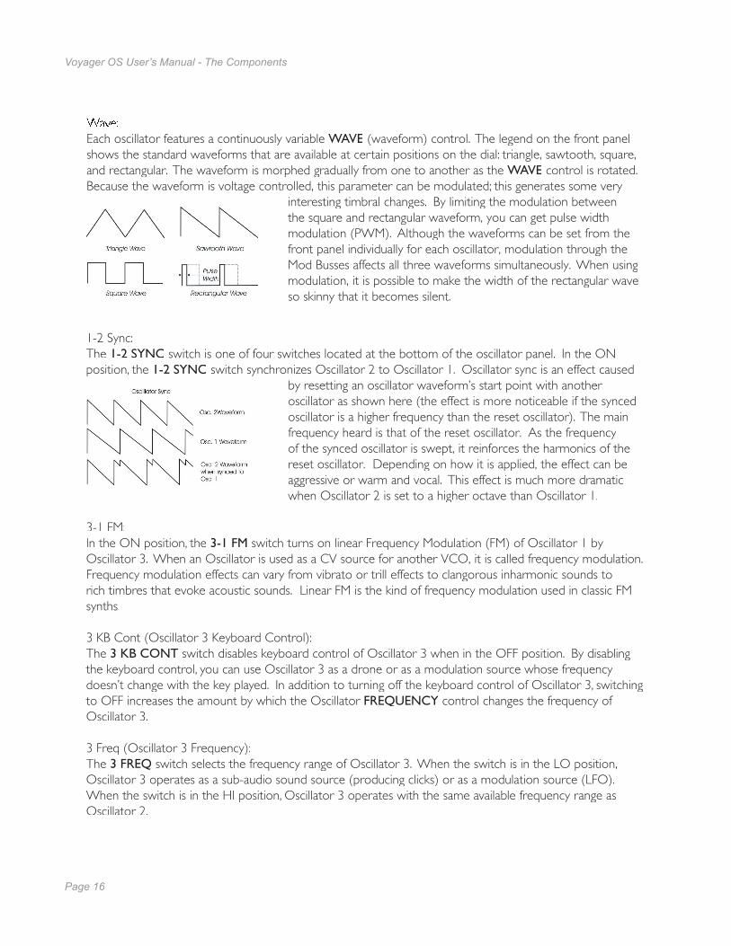
Wave: Each oscillator features a continuously variable WAVE (waveform) control. The legend on the front panel shows the standard waveforms that are available at certain positions on the dial: triangle, sawtooth, square, and rectangular. The waveform is morphed gradually from one to another as the WAVE control is rotated. Because the waveform is voltage controlled, this parameter can be modulated; this generates some very
interesting timbral changes. By limiting the modulation between the square and rectangular waveform, you can get pulse width modulation (PWM). Although the waveforms can be set from the front panel individually for each oscillator, modulation through the Mod Busses affects all three waveforms simultaneously. When using modulation, it is possible to make the width of the rectangular wave so skinny that it becomes silent.
1-2 Sync: The 1-2 SYNC switch is one of four switches located at the bottom of the oscillator panel. In the ON position, the 1-2 SYNC switch synchronizes Oscillator 2 to Oscillator 1. Oscillator sync is an effect caused
by resetting an oscillator waveform’s start point with another oscillator as shown here (the effect is more noticeable if the synced oscillator is a higher frequency than the reset oscillator). The main frequency heard is that of the reset oscillator. As the frequency of the synced oscillator is swept, it reinforces the harmonics of the reset oscillator. Depending on how it is applied, the effect can be aggressive or warm and vocal. This effect is much more dramatic when Oscillator 2 is set to a higher octave than Oscillator 1.
3-1 FM:In the ON position, the 3-1 FM switch turns on linear Frequency Modulation (FM) of Oscillator 1 by Oscillator 3. When an Oscillator is used as a CV source for another VCO, it is called frequency modulation. Frequency modulation effects can vary from vibrato or trill effects to clangorous inharmonic sounds to rich timbres that evoke acoustic sounds. Linear FM is the kind of frequency modulation used in classic FM synths.
3 KB Cont (Oscillator 3 Keyboard Control):The 3 KB CONT switch disables keyboard control of Oscillator 3 when in the OFF position. By disabling the keyboard control, you can use Oscillator 3 as a drone or as a modulation source whose frequency doesn’t change with the key played. In addition to turning off the keyboard control of Oscillator 3, switching to OFF increases the amount by which the Oscillator FREQUENCY control changes the frequency of Oscillator 3.
3 Freq (Oscillator 3 Frequency):The 3 FREQ switch selects the frequency range of Oscillator 3. When the switch is in the LO position, Oscillator 3 operates as a sub-audio sound source (producing clicks) or as a modulation source (LFO). When the switch is in the HI position, Oscillator 3 operates with the same available frequency range as Oscillator 2.
Page 16
Voyager OS User’s Manual - The Components
Page 17
Voyager OS User’s Manual - The Components
Related Oscillator Controls:
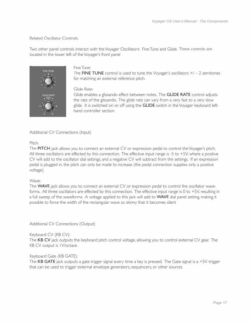
Two other panel controls interact with the Voyager Oscillators: Fine Tune and Glide. These controls are located in the lower left of the Voyager’s front panel
Fine Tune: The FINE TUNE control is used to tune the Voyager’s oscillators +/ – 2 semitones for matching an external reference pitch.
Glide Rate:Glide enables a glissando effect between notes. The GLIDE RATE control adjusts the rate of the glissando. The glide rate can vary from a very fast to a very slow glide. It is switched on or off using the GLIDE switch in the Voyager keyboard left-hand controller section.
Additional CV Connections (Input)
Pitch:The PITCH jack allows you to connect an external CV or expression pedal to control the Voyager’s pitch. All three oscillators are effected by this connection. The effective input range is -5 to +5V, where a positive CV will add to the oscillator dial settings, and a negative CV will subtract from the settings. If an expression pedal is plugged in, the pitch can only be made to increase (the pedal connection supplies only a positive voltage).
Wave:The WAVE jack allows you to connect an external CV or expression pedal to control the oscillator wave-forms. All three oscillators are effected by this connection. The effective input range is 0 to +5V, resulting in a full sweep of the waveforms. A voltage applied to this jack will add to WAVE dial panel setting, making it possible to force the width of the rectangular wave so skinny that it becomes silent.
Additional CV Connections (Output)
Keyboard CV (KB CV):The KB CV jack outputs the keyboard pitch control voltage, allowing you to control external CV gear. The KB CV jack outputs the keyboard pitch control voltage, allowing you to control external CV gear. The KB CVKB CV output is 1V/octave.
Keyboard Gate (KB GATE):The KB GATE jack outputs a gate trigger signal every time a key is pressed. The Gate signal is a +5V trigger that can be used to trigger external envelope generators, sequencers, or other sources.
Page 18
Voyager OS User’s Manual - The Components
Page 19
Voyager OS User’s Manual - The Components
C – The Filter Section
Filters are used to adjust the tone color of an audio signal. Filters modify sounds by rejecting some frequencies while allowing others to pass through. To understand the operation of fi lters and how they process sound, there are a few important terms to know.
In the original Minimoog, the Resonance control was called ‘Emphasis’. Many ofthe current Minimoog emulations (both hardware and software) use the term ‘Emphasis’ instead of ‘Resonance’ in the fi lter section to preserve the authenticvibe of the original hardware.
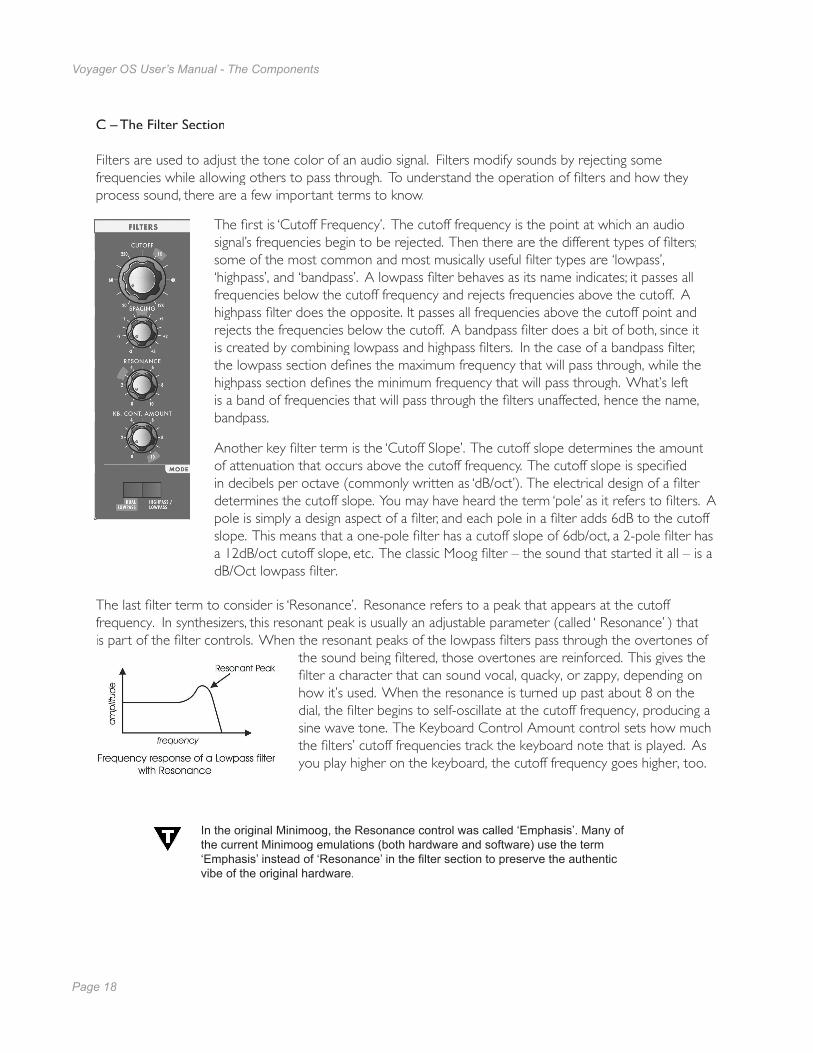
The fi rst is ‘Cutoff Frequency’. The cutoff frequency is the point at which an audio signal’s frequencies begin to be rejected. Then there are the different types of fi lters; some of the most common and most musically useful fi lter types are ‘lowpass’, ‘highpass’, and ‘bandpass’. A lowpass fi lter behaves as its name indicates; it passes all frequencies below the cutoff frequency and rejects frequencies above the cutoff. A highpass fi lter does the opposite. It passes all frequencies above the cutoff point and rejects the frequencies below the cutoff. A bandpass fi lter does a bit of both, since it is created by combining lowpass and highpass fi lters. In the case of a bandpass fi lter, the lowpass section defi nes the maximum frequency that will pass through, while the highpass section defi nes the minimum frequency that will pass through. What’s left is a band of frequencies that will pass through the fi lters unaffected, hence the name, bandpass.
Another key fi lter term is the ‘Cutoff Slope’. The cutoff slope determines the amount of attenuation that occurs above the cutoff frequency. The cutoff slope is specifi ed in decibels per octave (commonly written as ‘dB/oct’). The electrical design of a fi lter determines the cutoff slope. You may have heard the term ‘pole’ as it refers to fi lters. A pole is simply a design aspect of a fi lter, and each pole in a fi lter adds 6dB to the cutoff slope. This means that a one-pole fi lter has a cutoff slope of 6db/oct, a 2-pole fi lter has a 12dB/oct cutoff slope, etc. The classic Moog fi lter – the sound that started it all – is a dB/Oct lowpass fi lter.
The last fi lter term to consider is ‘Resonance’. Resonance refers to a peak that appears at the cutoff frequency. In synthesizers, this resonant peak is usually an adjustable parameter (called ‘ Resonance’ ) that is part of the fi lter controls. When the resonant peaks of the lowpass fi lters pass through the overtones of
the sound being fi ltered, those overtones are reinforced. This gives the fi lter a character that can sound vocal, quacky, or zappy, depending on how it’s used. When the resonance is turned up past about 8 on the dial, the fi lter begins to self-oscillate at the cutoff frequency, producing a sine wave tone. The Keyboard Control Amount control sets how much the fi lters’ cutoff frequencies track the keyboard note that is played. As you play higher on the keyboard, the cutoff frequency goes higher, too.
Page 18
Voyager OS User’s Manual - The Components
Page 19
Voyager OS User’s Manual - The Components
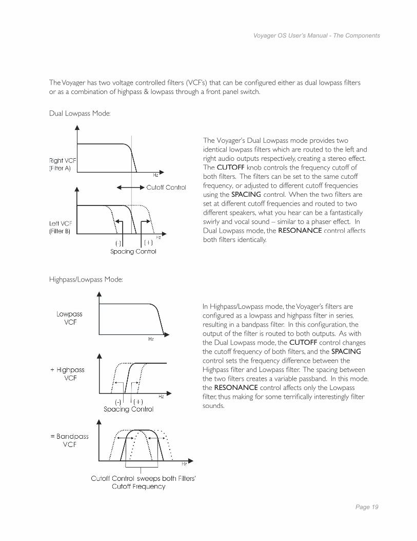
Dual Lowpass Mode:
The Voyager’s Dual Lowpass mode provides two identical lowpass fi lters which are routed to the left and right audio outputs respectively, creating a stereo effect. The CUTOFF knob controls the frequency cutoff of both fi lters. The fi lters can be set to the same cutoff frequency, or adjusted to different cutoff frequencies using the SPACING control. When the two fi lters are set at different cutoff frequencies and routed to two different speakers, what you hear can be a fantastically swirly and vocal sound – similar to a phaser effect. In Dual Lowpass mode, the RESONANCE control affects both fi lters identically.
Highpass/Lowpass Mode:
In Highpass/Lowpass mode, the Voyager’s fi lters are confi gured as a lowpass and highpass fi lter in series, resulting in a bandpass fi lter. In this confi guration, the output of the fi lter is routed to both outputs. As with the Dual Lowpass mode, the CUTOFF control changes the cutoff frequency of both fi lters, and the SPACINGcontrol sets the frequency difference between the Highpass fi lter and Lowpass fi lter. The spacing between the two fi lters creates a variable passband. In this mode, the RESONANCE control affects only the Lowpass fi lter, thus making for some terrifi cally interestingly fi lter sounds.
The Voyager has two voltage controlled fi lters (VCF’s) that can be confi gured either as dual lowpass fi lters or as a combination of highpass & lowpass through a front panel switch.

Page 20
Voyager OS User’s Manual - The Components
Page 21
Voyager OS User’s Manual - The Components
Filter Section Controls:
Cutoff: The CUTOFF knob is the main fi lter control. This sets the cutoff frequency of both fi lters in Dual Lowpass and Highpass/Lowpass mode.
In Dual Lowpass mode, the frequencies to the right of the indicator on the knob are the frequencies that are fi ltered out. The frequencies to the left of the indicator are the frequencies that are allowed to pass through the fi lter. This is why as you turn the control clockwise the cutoff frequency becomes higher and the sound becomes brighter. Of course, to hear the effect of a lowpass fi lter it helps to have a signal rich in harmonics which provides high frequencies to fi lter. A good example of a sound rich in harmonics is a sawtooth waveform.
In Highpass/Lowpass mode, the combination of highpass and lowpass fi lters forms a bandpass fi lter. In this mode, the CUTOFF control changes the center frequency of the passband.
Spacing: The SPACING control is used to determine the difference between the cutoff frequencies of the two fi lters in both Dual Lowpass mode and Highpass/Lowpass mode. The numbers on the legend around the control knob refer to octaves. When the SPACING control knob is centered, the cutoff frequencies of the two fi lters are identical and the fi lter sounds like a classic Moog Filter. Setting the SPACING control to +1 in Dual Lowpass mode means that the right fi lter has a cutoff frequency equal to where the CUTOFF control knob is set, and the left frequency has a cutoff frequency that is one octave higher than the right fi lter. This means when the CUTOFF control is swept, two resonant peaks are heard, giving the fi lter a unique quality.
In Highpass/Lowpass mode, the SPACING control sets the difference between the cutoff frequencies by shifting the Highpass fi lter cutoff frequency up or down. When the SPACING control is fully clockwise, the cutoff frequencies of the two fi lters are the same, making for a very narrow bandpass fi lter.
Resonance: The RESONANCE control causes feedback in the fi lter circuit that adds harmonic emphasis at the cutoff frequency. This control affects the Lowpass fi lter(s) in either fi lter mode, but not the Highpass fi lter. When the RESONANCE control is all the way down, the lowpass fi lters act as a tone control, rolling off the high end (treble) as the CUTOFF control is turned down. As the resonance increases, the fi lter begins to form a peak at the cutoff frequency. These peaks reinforce the harmonics of the signal being fi ltered, creating an effect that can be described as vocal, nasal, or (at high resonances) zappy. As the RESONANCE control is turned up the peak increases in strength until the control is set to about 8 or higher, where it begins to self-oscillate, creating sine waves with the same frequency as the cutoff frequency.
Keyboard Control Amount: The KEYBOARD CONTROL AMOUNT knob allows the fi lter cutoff to follow the key played on the Voyager keyboard. A higher key will cause a higher cutoff frequency. This allows a sound to retain its brightness as it is played higher on the keyboard.
Mode:The fi lter MODE switch selects either the Dual Lowpass confi guration (DUAL LP) or the Highpass/Lowpass confi guration (HP/LP).

Page 20
Voyager OS User’s Manual - The Components
Page 21
Voyager OS User’s Manual - The Components
D. The Envelopes Section Musical sounds have a start, middle and an end. For example, a plucked string sound starts with an initial burst of energy and then slowly fades out until it is silent. In synthesis terms, this progression is called an envelope – a shape that defi nes the changes that occur in a sound over time. An envelope can defi ne any aspect of change in a sound – volume, timbre, or pitch. The circuits that create envelope control signals in synthesizers are called Envelope Generators (EGs).
When triggered, EG’s produce a time-varying control voltage that has a specifi c start, middle and end profi le. The four parameters that defi ne this profi le are Attack, Decay, Sustain and Release, sometimes abbrevi-ated as ADSR.
Attack determines the character of the onset of the sound. The EG’s ATTACK knob controls this parameter by adjusting the time it takes for the envelope to go from zero to full value (in other words, the fade-in time). The DECAY control adjusts the second stage in the envelope’s evolution by determining the time that it takes for the signal to drop from the full level to the level set by the SUSTAIN control. The envelope will remain at the Sustain level as long as an envelope gate signal is present (i.e. a key is held down). When the gate signal is released, the RELEASE control determines the time it takes for the en-velope to transition from the Sustain level to zero (refer to the ADSR Envelope Signal fi gure below).
The Voyager has two identical EG circuits; one EG is dedicated to the fi lter (to control the cutoff frequency), and one is EG dedicated to the amplifi er (to control the volume). Both EG’s can also be used as a modulation sources or modulation control through the Modulation Busses..
Additional CV Connections
Filter :The FILTER jack allows you to connect an external CV or expression pedal to control the fi lter cutoff frequency. Both fi lters are effected by this connection, regardless of the fi lter mode setting. The effective input range is -5 to +5 V, where a positive CV will add to the fi lter cutoff dial setting, and a negative CV will subtract from the setting. Note that if an expression pedal is plugged into this jack, the cutoff can only be made to increase from the cutoff dial setting since the pedal connection supplies only a positive voltage.

Page 22
Voyager OS User’s Manual - The Components
Page 23
Voyager OS User’s Manual - The Components
Envelope Section Controls:
Attack: The ATTACK control sets the attack time of the corresponding envelope generator, from 1 msec to 10 seconds.
Decay: The DECAY control sets the decay time of the corresponding envelope generator, from 1 msec to 10 seconds.
Sustain: The SUSTAIN control sets the corresponding level for the sustained part of the envelope.
Release: The RELEASE control sets the release time of the corresponding envelope (the time for the envelope to transition from the sustain level to zero), from 1 msec to 10 seconds.
Amount To Filter :For the Filter Envelope, there is an AMOUNT TO FILTER control that adjusts the amount of the fi lter envelope signal that modulates the fi lter. The AMOUNT TO FILTER control has both positive and negative values. If it is set to a positive value (say ‘+2’), the envelope will add to the Filter CUTOFF dial setting. If it is a negative value (say ‘–2’), the envelope will subtract from the Filter CUTOFF dial setting.
Envelope Gate: Envelopes are triggered by a gate signal. The envelopes will sustain as long as a gate signal is present. When the gate is off, the Release portion of the envelope is executed as shown below. The switch labeled KEYB/ ON/EXT selects whether the envelopes are triggered from the keyboard, or from another gate source. When KEYB (Keyboard) triggering is selected, the envelopes are triggered by a gate trigger signal that is generated when a note on the keyboard is played. When the switch is set for ON/EXT (On/External), the envelope gate source defaults to ON if nothing is plugged into the ENV GATE jack on the Voyager back panel, and the envelopes will sustain at the level determined by their respective SUSTAIN controls. This is useful for keeping the envelopes sustaining without holding a key down, when you want to process an external audio signal through the fi lters with out using the keyboard, or to create drones.
Envelopes sustain as long as a Gate Trigger is present. The Release phase starts when the Gate Trigger stops.

Page 22
Voyager OS User’s Manual - The Components
Page 23
Voyager OS User’s Manual - The Components
Related Controls
Release Switch:The release time of the envelopes is set by their respective RELEASE control knob, but this control can also be switched OFF. On the Voyager OS , there’s a dedicated RELEASE switch located in the left-hand control panel for this.
NOTE: The Release function is actually a divider for the release time, so if the RELEASE control knob is set to 10, the release of the envelopes will not be absolutely abrupt with the RELEASE ON/OFF function switched off.
Additional CV Connections:
Gate (Envelope Gate Input):The GATE jack allows you to connect a footswitch or input a CV gate signal to remotely trigger both Envelope Generators. This input triggers the EG’s only when the front panel ENV GATE switch is set to ‘ON/EXT’. If the ENV GATE switch is set to ‘KEYB’, any input on the GATE jack will be ignored.
Release: The RELEASE jack allows you to connect a footswitch or input a CV gate signal. Pressing the footswitch or applying a gate signal (+5V) enables the Release phase of both Envelope Generators regardless of the setting of the RELEASE switch.
Rate (Rate Control Input):The RATE jack is a CV input for external control of the Voyager’s envelope time constants, using either a CV or expression pedal. The effective input range is -5V to +5V and effects both envelopes. A positive voltage applied to the RATE jack will decrease the attack, decay and release times from the envelope panel knob settings, and a negative voltage will increase the attack, decay and release times from the panel knob settingsas shown.
The envelope AD&R parameterswill expand and contract based on the voltage at the RATE jack.

Page 24
Voyager OS User’s Manual - The Components
Page 25
Voyager OS User’s Manual - The Components
E. The Output Section
The Voyager has two audio outputs. There is a Voltage Controlled Amplifi er (VCA) for each output, which allows for stereo functions such as panning or the dual lowpass fi ltering. The main control for the volume is the Master Volume control. The Volume Envelope Generator modulates the output VCAs.
Output Section controls:
Master Volume: The MASTER VOLUME knob is the main volume control. Full-clockwise is maximum output, full-counterclockwise silences the Voyager. .
Headphone Volume: This HEADPHONE VOLUME knob controls the volume that appears on the HEADPHONE OUTPUT jack. Full-clockwise is maximum output, full-counterclockwise silences the Voyager.
Headphone Output: The HEADPHONE OUTPUT connection is a 1⁄4” TRS jack that outputs the Voyager signal to a pair of stereo headphones.
Additional CV Connections:
Volume:The VOLUME jack allows you to connect an external CV or expression pedal to control the outputvolume. Both VCA’s are effected by this connection. The effective input range is 0 to +5V, where 0V = Volume OFF, and +5V = Full Volume.
Pan:The PAN jack allows you to connect an external CV or expression pedal to control panning betweenthe right and left outputs. The effective input range is -5 to +5V, where -5V = Fully Left and +5V = Fully Right. If an expression pedal is plugged into the PAN jack, the pedal will reach its fullpositive effect over just half of its useful travel, since it gets +5V from the PAN jack. Note also that you will not be able to pan left with the pedal without additional offset programming because the expression pedal voltage does not go below 0V.
NOTE: The Master Volume knob sets the maximum volume of the Voyager OS output regardless of the signal applied at the VOLUME jack.

Page 24
Voyager OS User’s Manual - The Components
Page 25
Voyager OS User’s Manual - The Components
F – The Modulation Buss Section
Modulation is the heart of making interesting sounds with analog subtractive synthesis. The Voyager’s two Modulation Busses open up a world of modulation possibilities that were not available on the original Minimoog.
The Modulation Busses allow you to select a variety of modulation sources, destinations, modulation controllers, and amounts. The two Mod Busses are labeled MOD BUS 1 and MOD BUS 2, and are identical in function. The control of each mod buss is selectable instead of being tied to a particular controller, and six controller options are available.
Each Mod Bus can select from six modulation sources, six destinations and six controllers. One of the available controllers is the MOD 1 input on the back panel. This input can accept either a CV or an expression pedal like the EP-2. When an expression pedal is used, the result is a foot controller that functions just like the Modulation Wheel to fade in and fade out the desired modulation. If nothing is plugged into the MOD 1 input when ‘MOD 1’ is selected as the Controller, the bus AMOUNT control sets the total modulation amount.
The diagram below shows the confi guration of a single Mod Bus, but the controls and selections for both busses are the same.

Page 26
Voyager OS User’s Manual - The Components
Page 27
Voyager OS User’s Manual - The Components
Two controls modify the amount of modulation sent to the destination: the selected controller (set with the CONTROLLER knob) and the AMOUNT control. When the selected controller is a performance control such as the Mod Wheel or Key Velocity, the modulation can be selectively varied from 0 to 100%. When the selected controller is an envelope, the modulation varies according to the envelope parameters. In both cases, the AMOUNT control always sets the maximum amount of modulation.
To try out a simple modulation effect, make the following settings:
On the LFO: - Set the RATE control to about 6 Hz - Set the WAVE control to the Triangle wave On Mod Bus 1: - Set the SOURCE control to ‘LFO’ - Set the DESTINATION control to ‘PITCH’ - Set the CONTROLLER selector to ‘MOD WHEEL’ - Set the AMOUNT control to 2
These settings allow the Mod Wheel performance control to be used to fade in the modulation, which should sound something like vibrato. This is a simple use of a Mod Bus. The fl exibility of the two Modula-tion Busses offer a wealth of modulation possibilities which make the Voyager OS an incredible sound design tool.
Modulation Bus Section Controls:
Source: The SOURCE control selects the source of the modulation. There are six selections available: - LFO (Low Frequency Oscillator) - OSC 1 (Oscillator 1) - OSC 2 (Oscillator 2) - OSC 3 (Oscillator 3) - NOISE - ON/MOD2: If nothing is plugged into the MOD2 jack, this selection is ON Destination: The DESTINATION control selects the destination of the modulation. The modulation destination is cho-sen in the same manner as the source. The modulation destination selections are: - PITCH (the pitch of all three oscillators) - OSC2 (the pitch of Oscillator 2 only) - OSC3 (the pitch of Oscillator 3 only) - FILTER (the Cutoff Frequency of the fi lter) - WAVE (the waveforms of all 3 oscillators) - LFO (the Low Frequency Oscillator)
Page 26
Voyager OS User’s Manual - The Components
Page 27
Voyager OS User’s Manual - The Components
Controller :The CONTROLLER dial selects from six modulation controller options. The Controller selections are: - MOD WHEEL: This allows the modulation source to be controlled from the Modulation Wheel in the left-hand controller section. - ON/MOD1: This allows the modulation source to be controlled by a CV or expression pedal plugged into the back-panel MOD1 jack. If nothing is plugged into the MOD1 jack when this is selected, the Mod Bus AMOUNT control will set the total amount of modulation. - VELOCITY: This allows the modulation source to be controlled by the keyboard velocity. - PRESSURE: This allows the modulation source to be controlled by keyboard aftertouch. - FILT. ENV: This allows the modulation source to be controlled by the Filter Envelope. - VOL. ENV: This allows the modulation source to be controlled by the Volume Envelope.
Amount:The AMOUNT control is used to set the maximum amount of modulation that is sent to the modulation destination. When the AMOUNT control is set to 0, no modulation will pass. When AMOUNT is set to 10, the maximum amount of modulation is sent to the destination when the selected performance control-ler is set to maximum (such as the Mod Wheel) or when the controller reaches maximum levels (such as the envelopes)
Additional CV Control
MOD 1:The MOD 1 jack accepts an expression pedal or control voltage from 0 to 5 Volts. With nothing plugged into this jack, the voltage here is 5V (the ‘ON’ state).
MOD 2:The MOD 2 jack allows you to apply an external modulation source into the MOD busses. The input accepts an expression pedal or a control voltage of –5 to +5. With nothing plugged into this jack, the voltage here is 5V (the ‘ON’ state). When the Mod Buss SOURCE control is set to ‘ON/MOD2’, the voltage applied to this jack becomes the Modulation Source.

Page 28
Voyager OS User’s Manual - The Components
Page 29
Voyager OS User’s Manual - The Components
G – The LFO
The Voyager OS has a dedicated Low Frequency Oscillator (LFO). The LFO produces triangle and square waves as well as stepped and smoothed Sample & Hold (S&H) signals over a range of approximately 0.2 to 50 Hz. The LFO signal is available as a modulation source on both Mod Busses.
For the Sample and Hold circuit, the LFO’s square wave is used as the S&H Trigger input, while the Voyager’s Noise source is used for the S&H Input signal. For each positive-going cycle of the LFO square wave, the voltage at the input of the S&H circuit is sampled and held until the next cycle. Since the sample source is Noise (a random signal), the voltage that appears at the output of the S&H circuit is a random voltage that changes in time with the LFO.
The Voyager’s CV Interface jacks on the back panel of the Voyager allow additional fl exibility with the Sample and Hold circuit. For example, if a plug is inserted into the S&H Gate input, it will disconnect the LFO trigger; an external gate signal can then be used to trigger the S&H circuit. Similarly, a plug inserted into the S&H Input jack disconnects the Noise source from the S&H input. In this circumstance when the S&H circuit is triggered, the voltage at the tip of the plug is held at the output of the S&H circuit. This makes it possible to get interesting modulation patterns such as the ‘staircase’ modulation shown below.
The Voyager’s Sample and Hold circuit can create more than just random signals –interesting stepped modulation patternsare also possible.
Page 28
Voyager OS User’s Manual - The Components
Page 29
Voyager OS User’s Manual - The Components
LFO/Sample and Hold Section Controls
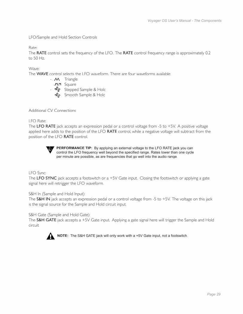
Rate: The RATE control sets the frequency of the LFO. The RATE control frequency range is approximately 0.2 to 50 Hz.
Wave:The WAVE control selects the LFO waveform. There are four waveforms available: - Triangle - Square - Stepped Sample & Hold - Smooth Sample & Hold
Additional CV Connections:
LFO Rate:The LFO RATE jack accepts an expression pedal or a control voltage from -5 to +5V. A positive voltage applied here adds to the position of the LFO RATE control, while a negative voltage will subtract from the position of the LFO RATE control.
NOTE: The S&H GATE jack will only work with a +5V Gate input, not a footswitch.
LFO Sync:The LFO SYNC jack accepts a footswitch or a +5V Gate input. Closing the footswitch or applying a gate signal here will retrigger the LFO waveform.
S&H In (Sample and Hold Input):The S&H IN jack accepts an expression pedal or a control voltage from -5 to +5V. The voltage on this jack is the signal source for the Sample and Hold circuit input.
S&H Gate (Sample and Hold Gate):The S&H GATE jack accepts a +5V Gate input. Applying a gate signal here will trigger the Sample and Hold circuit.
PERFORMANCE TIP: By applying an external voltage to the LFO RATE jack you can control the LFO frequency well beyond the specifi ed range. Rates lower than one cycle per minute are possible, as are frequencies that go well into the audio range.
Page 30
Voyager OS User’s Manual - The Components
Page 31
Voyager OS User’s Manual - The Components
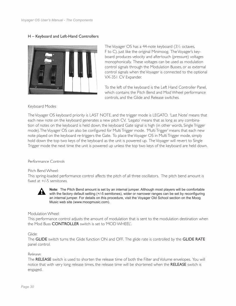
H – Keyboard and Left-Hand Controllers
The Voyager OS has a 44-note keyboard (31⁄2 octaves, F to C), just like the original Minimoog. The Voyager’s key-board produces velocity and aftertouch (pressure) voltages monophonically. These voltages can be used as modulation control signals through the Modulation Busses, or as external control signals when the Voyager is connected to the optional VX-351 CV Expander.
To the left of the keyboard is the Left Hand Controller Panel, which contains the Pitch Bend and Mod Wheel performance controls, and the Glide and Release switches.
Keyboard Modes
The Voyager OS keyboard priority is LAST NOTE, and the trigger mode is LEGATO. ‘Last Note’ means that each new note on the keyboard generates a new pitch CV. ‘Legato’ means that as long as any combina-tion of notes on the keyboard is held down, the keyboard Gate signal is high (in other words, Single Trigger mode). The Voyager OS can also be confi gured for Multi Trigger mode. ‘Multi Trigger’ means that each new note played on the keyboard re-triggers the Gate. To place the Voyager OS in Multi Trigger mode, simply hold down the top two keys of the keyboard as the unit is powered up. The Voyager will revert to Single Trigger mode the next time the unit is powered up unless the top two keys of the keyboard are held down.
Performance Controls
Pitch Bend Wheel: This spring-loaded performance control affects the pitch of all three oscillators. The pitch bend amount is fi xed at +/-5 semitones.
Note: The Pitch Bend amount is set by an internal jumper. Although most players will be comfortable with the factory default setting (+/-5 semitones), wider or narrower ranges can be set by reconfi guring an internal jumper. For details on this procedure, visit the Voyager Old School section on the Moog Music web site (www.moogmusic.com).
Modulation Wheel: This performance control adjusts the amount of modulation that is sent to the modulation destination when the Mod Buss CONTROLLER switch is set to ‘MOD WHEEL’.
Glide:The GLIDE switch turns the Glide function ON and OFF. The glide rate is controlled by the GLIDE RATEpanel control.
Release:The RELEASE switch is used to shorten the release time of both the Filter and Volume envelopes. You will notice that with very long release times, the release time will be shortened when the RELEASE switch is engaged.

Page 30
Voyager OS User’s Manual - The Components
Page 31
Voyager OS User’s Manual - The Components
PERFORMANCE TIP: The expressive use of the Pitch and Modulation Wheels is the key to breathing musical life into your performances. For example, the Pitch Wheel will allow you to perform pitch bends like a guitarist, or create on-the-fl y half and whole step modulations. The Mod Wheel can be programmed to introduce standard modulation effects like vibrato, tremolo or fi lter sweeps, or it can control something less expected, like the LFO rate. Although the actual performance technique with these controls is beyond the scope of this manual, we recommend listening to recordings of synthesizer players, guitarists and other soloists to learn the various ways these controls can be used effectively.
Left/Mono and Right Outputs:The LEFT/MONO and RIGHT outputs on the Voyager OS are unbalanced 1⁄4” TS jacks for use with standard TS instrument cables.
When just the LEFT/MONO output is connected, both channels are summed to this output. A stereo signal is created when both the LEFT/MONO and RIGHT outputs are used. When the Voyager Filter is set to ‘Dual Lowpass Mode’, the RIGHT output can be used to get a monophonic sound that is unaffected by the Filter’s SPACING control.
External Audio In:This is an unbalanced 1⁄4” TS input that accepts any instrument or line level signal and routes the signal to the Mixer. A dedicated EXTERNAL input control on the Mixer adjusts the signal level.
Mixer Out/Filter In:This is a 1⁄4” TRS jack that is used for inserting a processing device between the Voyager’s Mixer and Filters. The tip is the send and the ring is the return (see the illustration on page 14).
CV/Expression Inputs: The CV/Expression Inputs are 1⁄4” TS jacks color coded with a red nut. These jacks accept an input from an expression pedal such as the Moog EP-2, or a CV from -5V to +5V. Note that some inputs, such as the MOD 1 input, operate only from 0V to +5V; a negative CV applied here will have no effect.
IMPORTANT SAFETY NOTE – Do not alter the power connector in any way. Doing so can result in the risk of shock, injury or death. Be familiar with the safety instructions printed at the beginning of this manual. If the connector is damaged, refer servicing to qualifi ed personnel only.
I – The Back Panel
The back panel provides for all of the Voyager’s connectivity, including power, audio and CV expansion con-nections.
Power Connector:This is a standard AC power inlet. Use only a power cord designed to mate with this receptacle. The Voyager power supply is designed to work with power inputs of 100-240 VAC; 50-60 Hz.

Page 32
Voyager OS User’s Manual - The Components
Page 33
Voyager OS User’s Manual - Appendices
Gate/Footswitch Inputs:The Gate/Footswitch Inputs are 1⁄4” TS jacks color coded with a blue nut. These jacks accept an input from a footswitch (a momentary, normally-closed footswitch like the Moog FS-1) or a +5 Volt Gate Signal.
CV Output: The Keyboard Pitch CV (labeled ‘KB CV’) is available at this output. This CV is scaled to 1V/octave. The actual voltage corresponds to the last note played on the keyboard.
Gate Output:The Keyboard Gate (labeled ‘KB GATE’) is available at this output. This signal is a +5V trigger signal that is generated with each key press.
Accessory Port: The Voyager OS has a DB-25 connector which connects to the optional VX-351 Voyager CV Expander. This device outputs all the CV and Gate signals that are generated by the Voyager on 1⁄4” jacks. For more on the VX-351, see Appendix B.
PERFORMANCE TIP: You can use the Voyager OS to process any audio signal simply by plugging into the EXTERNAL AUDIO IN jack. To hear the external audio signal without having to hold down a key on the keyboard, set the ENV. GATE switch to ‘ON/EXT’. This will trigger the envelopes. Make sure that the Volume Envelope SUSTAIN control is set to maximum. The Volume Envelope will remain at its Sustain level until the ENV. GATE switch is changed to ‘KEYB’.
NOTE: The Sample and Hold input jack ONLY accepts a Gate input.

Page 32
Voyager OS User’s Manual - The Components
Page 33
Voyager OS User’s Manual - Appendices
Appendix A - Specifi cations
Type:Monophonic analog performance synthesizer
Sound Generation:3 Oscillators with continuously variable wave-form control, 1 Noise source, 5-input Mixer, 2 Filters, 2 Envelope Generators, 1 LFO,2 Programmable Modulation Busses, Glide and Fine Tune controls
Keyboard:44 keys (F-C)Transmits monophonic velocity and after-touch control voltages
Performance Controls:Pitch Wheel: +/-5 semitones (range is internally adjustable)Modulation Wheel: 0 to 100%Glide and Release Switches: On/OffMaster Volume Control: 0 to 100%
Back Panel:AC Power Inlet (universal power supply,
100-250 VAC, 50-60 Hz)Power ON/OFF switchStereo Audio Output jacks External Audio In jackMixer Out/Filter In jackCV/Gate jacks (14 inputs and 2 outputs
that allow external control of various CV and Gate functions)
Accessory Output Port (DB25 connector) for optional VX-351 CV Expander
Outputs:Stereo Audio Output: Two 1⁄4” jacks on
back panelHeadphone Output: One 1⁄4” TRS jack on
front panel. Dedicated Headphone Volume control.
Dimensions: 30.5” W x 18” D x 3” H (panel fl at)
or30.5”W x 18”D x 12” H (w/panel fully upright)
Weight:40lbs (18.2 kg)
Specifi cations subject to change without notice
Page 34
Voyager OS User’s Manual - Appendices
Page 35
Voyager OS User’s Manual - Appendices
Appendix B - VX-351 CV Expander
Flash back to the late 60’s: Back in the day, a synthesizer was a behemoth of panels and patch cords. They were known as modular synthesizers, because each function of the synthesizer was contained in a single module. A synthesizer was a collection of modules, and the instrument produced no sound until the proper connections were made between modules using patch cables. This approach afforded the synthesist serious creative fl exibility, and the results of creative “what if ?” thinking often yielded amazing results. The approach was not without its drawbacks, however, which include:
Space – a modular synth can take up a lot of space. Time – creating sounds from scratch takes a lot of practice, patience, and time. Repeatability – documenting a sound is a tedious, labor-intensive process, and not always accurate Cost - a good modular synth takes serious money to assemble.
Enter the Minimoog; a portable synthesizer where the most musically useful connections are already in place and permanently wired. Sounds are created quickly and effi ciently using the various knobs and switches of the well laid out front panel (no patch cords needed!). Also, sounds are easy to document using patch templates, and, due to its smaller size and weight, the synth can actually be carried to gigs without having to rely on a road crew. Finally, a serious synthesizer made for the working musician.
Flash forward to today: The Minimoog Voyager Old School is based on the concept of the Minimoog. It is a portable analog synthesizer with all the basic connections for making great electronic sounds. From its front panel, the Voyager OS offers even more functions than the original Minimoog, and provides expansion capabilities through back panel connections that work just like the connections found on a modular synth. In fact, the Voyager OS can become the foundation of modular system. However, in order to take full advantage of this capability, you need a way to access all of the Voyager’s control voltage signals, both incoming and outgoing.
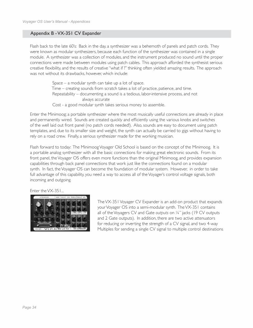
Enter the VX-351...
The VX-351 Voyager CV Expander is an add-on product that expands your Voyager OS into a semi-modular synth. The VX-351 contains all of the Voyagers CV and Gate outputs on 1⁄4” jacks (19 CV outputs and 2 Gate outputs). In addition, there are two active attenuators for reducing or inverting the strength of a CV signal, and two 4-way Multiples for sending a single CV signal to multiple control destinations.

Page 34
Voyager OS User’s Manual - Appendices
Page 35
Voyager OS User’s Manual - Appendices
Connecting the VX351:
Make all connections as described below with the Voyager powered OFF
To connect the VX-351, locate the male end (the end with recessed pins) of the DB-25 cable - this is the end that plugs into the connector on the Voyager’s back panel labeled “ACCESSORY PORT” Align the cable properly and make the connection. Use the thumbscrews to lock the connection. Be careful not to force or cross thread the thumbscrews in the accessory port’s female threads. Following this, connect the other end of the cable to the connector on the VX-351 labeled “FROM ACCESSORY PORT”.
Now let’s start with a basic sound and see how the VX-351 can work with the Voyager.
- Power up the Voyager OS keyboard- Set the panel controls to the default confi guration.- Using a 1⁄4“ patch cord, plug one end into the VX-351’s LFO triangle output. Plug the other end into the Voyager keyboard Filter Control Input.- Play a note on the Voyager and you will hear the LFO modulating the Filter’s Cutoff. Adjusting the Voyager’s LFO RATE control will change the rate that the Filter Cutoff moves up and down. This demonstrates a basic patch with the VX-351.
- Now disconnect the cable from the Voyager’s Filter Control and connect it to the IN of one of the VX-351 Attenuators. Set the Attenuator amount to zero. Using another 1⁄4” cable, make a connection from the VX-351 Attenuator OUT to the Filter Control Input. - Play a note and gradually increase the Attenuator amount. You will notice that the amount of modulation will increase. An Attenuator is used to set the amount of a CV Source that passes to the Destination.
This is a very basic use for the VX-351, but it demonstrates the fundamental concept of how to use it: a source always goes to a destination. Using this fundamental concept, you can patch together additional modulations and get as complex as you like.
NOTE: The Voyager OS does not require the VX-351 output adapter to be installed
PERFORMANCE TIP: As you make CV and Gate connections, think of the output jacks as your Sources (like the LFO triangle wave in the above example), and the input jacks as your Destinations (like the Filter Control Input in the above example).

Page 36
Voyager OS User’s Manual - Appendices
Page 37
Voyager OS User’s Manual - Appendices
VX-351 CV Output Expander - Description
The following is a description of the outputs and functions contained in the VX-351 CV Output Expander.
TOUCHThis group of four outputs is not used with the Voyager OS.
KBDThis group of outputs is generated from the Voyager’s Keyboard. There are three control voltages (Pitch, Velocity and Pressure) and one gate signal.
PITCH: This is the CV determined by the note that is played on the Keyboard. It is the same voltage used for determining the pitch of the Voyager’s Voltage Controlled Oscillators.
VEL: This is the CV determined by the velocity used to press a key. PRESS: This is the CV determined by how much pressure is exerted on a key after it is pressed.GATE: This is the gate signal generated when a key is pressed.
WHEELSThis group of outputs is generated from the Voyager keyboard’s Left Hand Controller Wheels.
PITCH: This is the CV generated from the Pitch Wheel.MOD: This is the CV generated from the Mod Wheel.
PEDALSThis group of outputs is generated from the MOD1 and MOD2 jacks on the rear panel of the Voyager.
MOD1: This is the CV generated from the MOD1 input. The MOD1 Input is a CV input on the Voyager that determines how much of the PEDAL/ON Mod Bus Source goes to the PEDAL/ON Mod Bus Destination. With nothing plugged into the MOD1 jack, the voltage that’s present at the MOD1 jack is +5V. When a CV is plugged in to the MOD1 input, that voltage replaces the +5 Volt signal at the MOD1Input. The Voltage that appears at the MOD1 Input is duplicated at the MOD1 output.
MOD2: This is the CV generated from the MOD2 input. The MOD2 Input is a CV input on theVoyager that is an external modulation source for the Mod Busses. With nothing plugged intothe MOD2 jack, the voltage that’s present at the MOD2 jack is +5V. When a CV is pluggedin to the MOD2 input, that voltage replaces the +5 Volt signal at the MOD2 Input. The Voltagethat appears at the MOD2 Input is duplicated at the MOD2 output.
LFOThis group of outputs is generated from the Voyager’s LFO. There are two CV waveforms available here (triangle and square) and both can be used at the same time
TRIANGLE: This is the triangle wave output of the LFO.SQUARE: This is the square wave output of the LFO.

Page 36
Voyager OS User’s Manual - Appendices
Page 37
Voyager OS User’s Manual - Appendices
BUSSES: This group of outputs is generated by the Mod Buss signals. They are the Modulation source after being shaped by the SHAPING signal at the level determined by the AMOUNT control and the MOD WHEEL or signal at the MOD1 Input jack
WHEEL: This is the output of the Mod Wheel Mod Buss. It is the Mod Wheel SOURCE shaped by theSHAPING signal. The level is determined by the AMOUNT control and the MOD WHEEL.
PEDAL: This is the output of the Pedal/On Mod Buss. It is the Pedal/On SOURCE shaped by theSHAPING signal. The level is determined by the AMOUNT control and the signal at theMOD1 Input jack.
ENVSThis group of outputs is the output of the Envelope Generators.
FILTER: This is the CV output of the Filter Envelope Generator.VOLUME: This is the CV output of the Volume Envelope Generator.
S & HThis group of outputs is generated by the Sample and Hold Circuit.
STEP: This is the output of the Sample and Hold Circuit. SMOOTH: This is the smoothed output of the Sample and Hold Circuit.
ATTENUATORSThe VX-351 contains two attenuators. An attenuator is used to reduce the amount of a CV signal. The attenuators have an input jack, an output jack, and a knob. The knob sets the amount of the signal present at the input jack that passes to the output jack. When the knob is set to fully clockwise, the full input signal passes to the output. When the knob is fully counter-clockwise, no signal passes to the output
MULTThe VX-351 contains two 4-way Multiples, or ‘Mults’. A Mult is used to distribute a single source to multiple destinations. An example is connecting the Voyager’s LFO to the Volume, Filter and Pan Control Inputs. In this case, all three of those parameters will be controlled simultaneously by the LFO.
NOTE: A Mult is NOT a mixer. Never apply more than one CV source to a mult! Combining two or more CVs in a Mult can cause them to add together in a way that can be damaging to some control inputs! If you wish to combine several CV’s, you must use a CV mixer (like the must use a CV mixer (like the mustCP-251 Control Processor’s Mixer) to safely mix these signals.

Page 38
Voyager OS User’s Manual - Appendices
Page 39
Voyager OS User’s Manual - Appendices
SECTION PARAMETER EFFECTIVE RANGE
TOUCH(Note 1)
X N/A
Y N/A
A N/A
GATE N/A
KBD
PITCH (Note 2) -0.916V to 2.667V Nominal
VEL -5 to + 5V
PRESS -5 to + 5V
GATE +5V ON, 0V OFF
WHEELSPITCH -5 to +5V
MOD -5 to +5V
PEDALSMOD1 (Note 3) -5 to +5V
MOD2 (Note 3) -5 to +5V
LFOTRIANGLE +/- 2.5V
SQUARE +3V
BUSSESWHEEL (Note 4) -4 to +4V Nominal
PEDAL (Note 5) -4 to +4V Nominal
ENVSFILTER 0 - 5V
VOLUME 0 - 5V
S&HSTEP -2 to +2V Nominal
SMOOTH -2 to +2V Nominal
NOISE NOISE +/- 1V Nominal
The table below shows the effective ranges of the VX-351 Outputs.
Note 1: The Touch Surface jacks are non-functional when the VX-351 is used with the Voyager OS.
Note 2: The range shown is the Keyboard Pitch voltage range over the Voyager’s 31⁄2 octave key-board (F-C). Keyboard Pitch is scaled for 1 V/octave.
Note 3: The MOD1 and MOD2 outputs default to +5V if nothing is connected to the MOD1 and MOD2 inputs.
Note 4: The jack labeled “WHEEL” outputs the signal from the Voyager OS Mod Bus 1.
Note 5: The jack labeled “PEDAL” outputs the signal from the Voyager OS Mod Bus 2.
VX-351 CV Expander Outputs
Page 38
Voyager OS User’s Manual - Appendices
Page 39
Voyager OS User’s Manual - Appendices
VX-351 CV OUTPUT EXPANDER
SOURCE DESTINATION
KBD Pitch KBD Velocity KBD Pressure
KBD GatePitch WheelMod Wheel
MOD1MOD2
LFO TriangleLFO Square
Mod Wheel Mod BusPedal/On Mod Bus
Filter EnvVol Env
S&H StepS&H Smooth
NoiseAtten 1/AmountAtten 2/Amount
Mult A1Mult A2Mult A3Mult A4Mult B1Mult B2Mult B3Mult B4
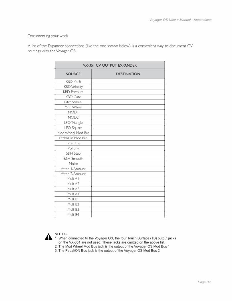
Documenting your work
A list of the Expander connections (like the one shown below) is a convenient way to document CV routings with the Voyager OS.
NOTES:1. When connected to the Voyager OS, the four Touch Surface (TS) output jacks on the VX-351 are not used. These jacks are omitted on the above list.2. The Mod Wheel Mod Bus jack is the output of the Voyager OS Mod Bus 13. The Pedal/ON Bus jack is the output of the Voyager OS Mod Bus 2

Page 40
Voyager OS User’s Manual - Appendices
Page 41
Voyager OS User’s Manual - Appendices
The following are some simple ways to use the VX-351 with the Voyager OS. Gather up some 1⁄4” patch cords and try these suggestions:
1. Use the Mod Wheel to control Volume
This will confi gure the Mod Wheel as a volume controller. Perform the following steps:
- Set the panel controls to the default confi guration.- Set the Mod Bus 1 controls as follows: SOURCE: ON/MOD2 DESTINATION: FILTER CONTROLLER: MOD WHEEL AMOUNT: 6- Using a patch cord, make a connection between the VX-351 ‘BUSSES WHEEL’ jack and the
Voyager’s VOLUME jack.- Play a note and move the Mod Wheel. You’ll hear the sound fade in and out as you move the
Mod Wheel back and forth.- Now adjust the Filter CUTOFF to 60 (about 9 o’clock) and turn the GLIDE and RELEASE
switches ON. Add a slight bit of LFO Pitch modulation from Mod Bus 2, and you have atheremin-like patch where the volume and timbre is completely controlled by your left handwhile you play the notes with your right hand.
2. Use the LFO to auto-trigger the Voyager’s Envelopes
This is an alternative to triggering a sound from the Voyager by pressing a key. In this example, the last key you press will determine the pitch, but the LFO will continuously trigger the start of the envelopes.
- Using a patch cord, make a connection between the VX-351 LFO Square Wave jack and the Voyager’s Envelope Gate (ENV GATE) Input.
- Switch the front panel ENVELOPE GATE switch to ‘ON/EXTERNAL’. You should immediatelyhear a note repeating at the LFO rate.
- For a bit of sonic exploration with this setup, try adjusting the LFO RATE control while you tweakthe FILTER CUTOFF, RESONANCE and Envelope controls.
3. Use the Pitch Wheel to control the waveshape
Here’s a way to make your Pitch Bends stand out:
- Set the panel controls to the default confi guration.- Using a patch cord, make a connection between the VX-351 ‘WHEELS PITCH’ jack and the input of an Attenuator.- With a second patch cord, make a connection between the Attenuator output jack and the Voyager’s WAVE jack.- Set the Attenuator to ‘5’ (12 o’clock)- Play a few notes as you adjust the Pitch Wheel. In addition to affecting the pitch, it will now also introduce a timbre change as the waveform is modulated. This is a handy way to add emphasis to your Pitch Bends. This basic technique also works well when the Pitch Wheel output is routed to affect the Filter Cutoff.

Page 40
Voyager OS User’s Manual - Appendices
Page 41
Voyager OS User’s Manual - Appendices
The Moogerfooger® CP-251 Control Processor makes an ideal companion to the Voyager OS. The CP-251 provides an LFO with two waveforms (Triangle/Square), a Sample & Hold circuit with two outputs (stepped/smooth), a Lag Processor, a Noise source, a Mixer and two active Attenuators. The combination of Voyager, VX-351and CP-251 is very much like having a small Modular synthesizer. The nice thing is that the most basic connections are already made in the Voyager, so the CP-251 and VX-351 add an extra level of modulation signal fl exibility.
Here are some possible confi gurations for using the CP-251 with the Voyager. Grab some 1⁄4” patch cords and try these ideas!
1. Simple confi gurations using the LFO
The LFO in the CP-251 can be used for common modulations such as vibrato, tremolo, auto-pan andmodulated fi lter effects, freeing up the Voyager’s LFO for other uses.
To try any of the examples shown below, begin by connecting the CP-251’s LFO Triangle output to an At-tenuator Input, then follow the example to complete the modulation routing.
To create Vibrato:Using a patch cord, make a connection from the CP-251 Attenuator Output to the Voyager’s PITCH jack. On the CP-251, set the LFO RATE control to 6 Hz (about 1 o’clock), and adjust the ATTEN-UATOR control to about ‘0.5’ on the dial (a very low amount). This confi guration will produce a constant mild vibrato. Setting the CP-251’s LFO RATE control considerably higher will result in wild FM textures.
To create Tremolo:Using a patch cord, make a connection from the CP-251 Attenuator Output to the Voyager’s VOLUME jack. On the CP-251, set the LFO RATE control to 6 Hz (about 1 o’clock), and adjust theATTENUATOR control to ‘10’ on the dial. This will produce a constant tremolo effect. Adjust the LFO Rate to taste. For a sharp, volume-chopping effect, use the CP-251’s LFO Square wave output in place of the LFO Triangle out.
To produce Auto-Panning:Using a patch cord, make a connection from the CP-251 Attenuator Output to the Voyager’s PAN jack. On the CP-251, set the LFO RATE control to 6 Hz (about 1 o’clock), and adjust the AT-TENUATOR control to ‘10’ on the dial. This will produce a constant panning effect. Adjust the LFO Rate to taste.
Appendix C - Using the CP-251 with the Voyager

Page 42
Voyager OS User’s Manual - Appendices
Page 43
Voyager OS User’s Manual - Appendices
To produce a modulated fi lter effect:Using a patch cord, make a connection from the CP-251 Attenuator Output jack to the Voyager’s FILTER jack. On the CP-251, set the LFO RATE control to 6 Hz (about 1 o’clock), and adjust the ATTENUATOR to about ‘2’ on the dial. This will produce a cyclical tonal variation as the fi lter cutoff frequency is modulated. Setting the CP-251’s LFO RATE control considerably higher will result in wild timbral textures, while a very low setting will create a slowly evolving fi lter sweep.
2. Inverting the keyboard CV to the Filters
This is a handy little trick that can be used to lower the fi lter cutoff as you play higher on the keyboard. This effect mimics certain acoustic instruments like a cello, whose tone gets duller as higher notes are played.
- Set the panel controls to the default confi guration.- Turn the Voyager Filter KB. CONT. AMOUNT control to ‘0’- Using a patch cord, connect the VX-351 KBD PITCH output to the CP-251 Attenuator Input. - With a second patch cord, connect the Attenuator output to the Voyager’s FILTER jack.- Set the CP-251’s ATTENUATOR control level to -5.
Play a scale up the keyboard, from low to high, and you’ll notice that the sound gets much duller. Adjust the FILTER CUTOFF and ATTENUATOR controls to taste.
3. Creating Sample and Hold staircase patterns
A Sample and Hold circuit can be used for more than generating random voltages. One type of modulation pattern that can be achieved is called ‘Staircase’ modulation. It is achieved by feeding a slow triangle wave into the Sample and Hold circuit and sampling that input at a high rate, effectively chopping the triangle wave into discreet voltage levels that resembles a staircase. We’ll use two LFO’s for this; a slow one for the input and a fast one for the trigger.
- Set the panel controls to the default confi guration.- Set the Voyager’s LFO rate to about .4 Hz. - Using a patch cable, make a connection from the VX-351’s LFO triangle output jack to the
Voyager’s Sample and Hold Input jack (S&H IN).- Set the CP-251’s LFO RATE control to about 6 Hz (about 1 o’ clock on the dial). - Using another patch cable, make a connection from the CP-251’s LFO square wave output jack to
the Voyager’s Sample and Hold Gate Input jack (S&H GATE). - Set the Voyager’s LFO WAVE control to the S&H position.- Set the Mod Bus 1 controls as follows: SOURCE: LFO DESTINATION: PITCH CONTROLLER: MOD WHEEL AMOUNT: 6
Play a note and move the Mod Wheel forward. You should hear the pitch modulated by an ‘up & down’ staircase waveform.

Page 42
Voyager OS User’s Manual - Appendices
Page 43
Voyager OS User’s Manual - Appendices
PERFORMANCE TIP: There may be times when you want a wider control range than a single CV provides. It’s possible to increase the control range of a CV using a Mult and the Mixer in the CP-251. Begin by connecting the CV to a Mult, and then make connections from the Mult to the Mixer 1 & Mixer 2 inputs. Set the Mixer 1 & 2, and Master levels to maximum, then route the output to your desired input. (Note: Although the Mixer is effec-tively doubling the CV signal in this confi guration, the Mixer output cannot exceed about +/-7.5V)
Connecting other CV compatible equipment
We’ve covered some basic uses of the Voyager and the VX-351 and CP-251. Other CV compatible equipment like our Moogerfooger®equipment like our Moogerfooger®equipment like our Moogerfooger analog effects can be incorporated to further expand the sonic palette.Here are some things you could try with a Voyager, a VX-351and our Moogerfoogers:
- Use the Voyager’s Filter Envelope to control the Sweep of a MF-103 12-Stage Phaser.- Use the Voyager’s Mod Wheel to control the Rate of the MF-103 12-Stage Phaser.- Use the Voyager’s Mod Wheel to control the Mix on the MF-102 Ring Modulator.- Use the Voyager’s Noise Output to add roughness to the MF-101’s Filter Cutoff.- Use the Voyager’s Keyboard Pitch Output to control the VCO in the MF-107 FreqBox.
With all of the control options provided, the possibilities for sound creation are nearly limitless!
We’ve just scratched the Surface
The examples provided here are just a few of the synthesis possibilities afforded by the Voyager OS and our line of CV Expanders. Other CV compatible equipment can be connected as well; just keep in mind that you should always connect a source to a destination, and that you shouldn’t combine multiple source CVs without a mixer. We encourage you to experiment, as there are many possibilities for exploring synthesis – whether you are trying to duplicate a sound or effect you heard, or if you are trying to make a sound that nobody’s heard before. Remember - experimentation is part of the fun!
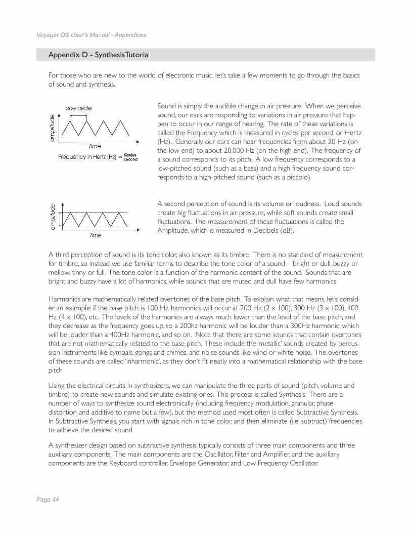
Page 44
Voyager OS User’s Manual - Appendices
Page 45
Voyager OS User’s Manual - Appendices
Appendix D - SynthesisTutorial
For those who are new to the world of electronic music, let’s take a few moments to go through the basics of sound and synthesis.
Sound is simply the audible change in air pressure. When we perceive sound, our ears are responding to variations in air pressure that hap-pen to occur in our range of hearing. The rate of these variations is called the Frequency, which is measured in cycles per second, or Hertz (Hz). Generally, our ears can hear frequencies from about 20 Hz (on the low end) to about 20,000 Hz (on the high end). The frequency of a sound corresponds to its pitch. A low frequency corresponds to a low-pitched sound (such as a bass) and a high frequency sound cor-responds to a high-pitched sound (such as a piccolo).
A second perception of sound is its volume or loudness. Loud sounds create big fl uctuations in air pressure, while soft sounds create small fl uctuations. The measurement of these fl uctuations is called theAmplitude, which is measured in Decibels (dB).
A third perception of sound is its tone color, also known as its timbre. There is no standard of measurement for timbre, so instead we use familiar terms to describe the tone color of a sound – bright or dull, buzzy or mellow, tinny or full. The tone color is a function of the harmonic content of the sound. Sounds that are bright and buzzy have a lot of harmonics, while sounds that are muted and dull have few harmonics.
Harmonics are mathematically related overtones of the base pitch. To explain what that means, let’s consid-er an example: if the base pitch is 100 Hz, harmonics will occur at 200 Hz (2 x 100), 300 Hz (3 x 100), 400 Hz (4 x 100), etc. The levels of the harmonics are always much lower than the level of the base pitch, and they decrease as the frequency goes up, so a 200hz harmonic will be louder than a 300Hz harmonic, which will be louder than a 400Hz harmonic, and so on. Note that there are some sounds that contain overtones that are not mathematically related to the base pitch. These include the ‘metallic’ sounds created by percus-sion instruments like cymbals, gongs and chimes, and noise sounds like wind or white noise. The overtones of these sounds are called ‘inharmonic’, as they don’t fi t neatly into a mathematical relationship with the base pitch.
Using the electrical circuits in synthesizers, we can manipulate the three parts of sound (pitch, volume and timbre) to create new sounds and simulate existing ones. This process is called Synthesis. There are anumber of ways to synthesize sound electronically (including frequency modulation, granular, phasedistortion and additive to name but a few), but the method used most often is called Subtractive Synthesis. In Subtractive Synthesis, you start with signals rich in tone color, and then eliminate (i.e. subtract) frequencies to achieve the desired sound.
A synthesizer design based on subtractive synthesis typically consists of three main components and three auxiliary components. The main components are the Oscillator, Filter and Amplifi er, and the auxiliarycomponents are the Keyboard controller, Envelope Generator, and Low Frequency Oscillator.
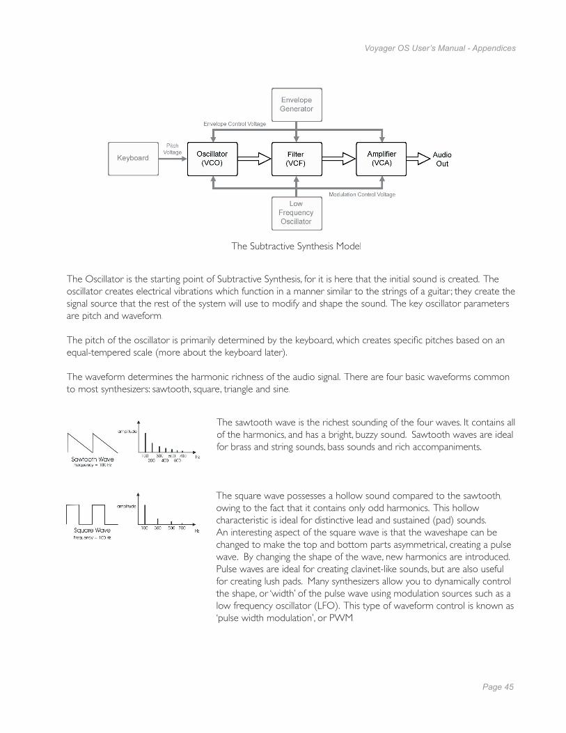
Page 44
Voyager OS User’s Manual - Appendices
Page 45
Voyager OS User’s Manual - Appendices
The Oscillator is the starting point of Subtractive Synthesis, for it is here that the initial sound is created. The oscillator creates electrical vibrations which function in a manner similar to the strings of a guitar ; they create the signal source that the rest of the system will use to modify and shape the sound. The key oscillator parameters are pitch and waveform.
The pitch of the oscillator is primarily determined by the keyboard, which creates specifi c pitches based on an equal-tempered scale (more about the keyboard later).
The waveform determines the harmonic richness of the audio signal. There are four basic waveforms common to most synthesizers: sawtooth, square, triangle and sine.
The sawtooth wave is the richest sounding of the four waves. It contains all of the harmonics, and has a bright, buzzy sound. Sawtooth waves are ideal for brass and string sounds, bass sounds and rich accompaniments.
The square wave possesses a hollow sound compared to the sawtooth, owing to the fact that it contains only odd harmonics. This hollow characteristic is ideal for distinctive lead and sustained (pad) sounds. An interesting aspect of the square wave is that the waveshape can be changed to make the top and bottom parts asymmetrical, creating a pulse wave. By changing the shape of the wave, new harmonics are introduced. Pulse waves are ideal for creating clavinet-like sounds, but are also useful for creating lush pads. Many synthesizers allow you to dynamically control the shape, or ‘width’ of the pulse wave using modulation sources such as a low frequency oscillator (LFO). This type of waveform control is known as ‘pulse width modulation’, or PWM.
The Subtractive Synthesis Model

Page 46
Voyager OS User’s Manual - Appendices
Page 47
Voyager OS User’s Manual - Appendices
Like the square wave, the triangle wave only contains odd harmonics, but the levels of the harmonics in a triangle wave are much less. The triangle wave has a soft, slightly buzzy sound that is suitable for high-pitched leads (like a fl ute) or adding a beefy sub-bass to bass sounds.
The sine wave is the purest waveform of them all. It has no harmonics, so it produces a very pure tone. Because of this, sine waves generally aren’t used as primary audio signals, but are often used to reinforce or enhance other waves. They are also used as modulation sources.
Synthesizers often have more than one oscillator, and each oscillator usually has its own dedicated frequency, waveform and level (volume) parameters. Several oscillators make possible rich and complex sound source confi gurations. Some synthesizers also permit external audio signals to serve as sound sources, allowing you to combine them with the oscillators, or process the external audio by itself using the synthesizer compo-nents.
The combined sound sources are routed to the Filter, a circuit that removes or reduces frequencies (and in some cases, emphasizes them). Although there are several fi lter types designed to remove high, low and middle frequencies, most synths offer at least one type, and most often it’s a Lowpass fi lter.
A Lowpass fi lter gets its name because it allows low frequencies to pass through while removing or reducing the high frequencies. The point at which the fi lter works to remove high frequency signals is called the Cutoff. Above the cutoff, frequencies are gradually reduced according to the fi lter’s ‘slope’, which is a measure of how well the fi lter works. The slope of a fi lter is expressed in decibels per octave (dB/Oct). The Voyager fi lter is rated at 24 dB/Oct, which creates a dramatic reduction in unwanted frequencies. This is a highly desirable quality for subtractive synthesis.
Another important fi lter parameter is the fi lter resonance. Resonance amplifi es the frequencies at the cutoff frequency, emphasizing any signal frequencies that appear there. It’s possible to adjust the resonance control to the point where the fi lter actually oscillates. When this occurs, the oscillation frequency is the same as the cutoff frequency.
The Filtered signal is routed to the Amplifi er, which controls the gain (volume) of the signal. The Ampli-fi er controls the dynamics of a sound, turning it on and off as you play. The Amplifi er is usually paired with an Envelope Generator (described below). The gain of the amplifi er follows the contours of the Envelope Generator signal, shaping the sound from start to fi nish.
The Oscillator, Filter and Amplifi er are voltage controlled, meaning that they respond to changes in voltages. For the Oscillator, it means the higher the voltage, the higher the pitch. For the Filter, it means the higher the voltage, the higher the cutoff frequency. For the Amplifi er, this means the higher the voltage, the greater the volume. Since each of the three main components respond to a voltage, the entire synthesis system thus has a common control element. This provides great fl exibility for sound programming, and allows auxiliary components, like Envelope Generators and Low Frequency Oscillators (which generate control voltages) to further vary the sound.
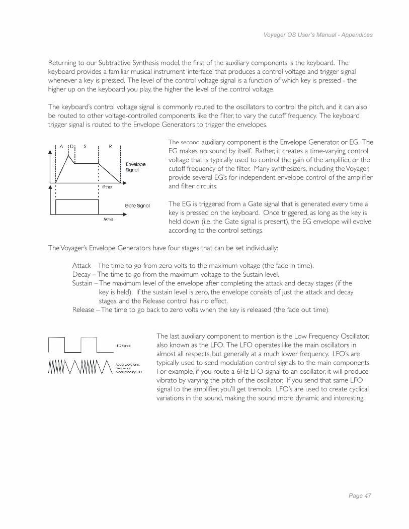
Page 46
Voyager OS User’s Manual - Appendices
Page 47
Voyager OS User’s Manual - Appendices
Returning to our Subtractive Synthesis model, the fi rst of the auxiliary components is the keyboard. The keyboard provides a familiar musical instrument ‘interface’ that produces a control voltage and trigger signal whenever a key is pressed. The level of the control voltage signal is a function of which key is pressed - the higher up on the keyboard you play, the higher the level of the control voltage.
The keyboard’s control voltage signal is commonly routed to the oscillators to control the pitch, and it can also be routed to other voltage-controlled components like the fi lter, to vary the cutoff frequency. The keyboard trigger signal is routed to the Envelope Generators to trigger the envelopes.
The second auxiliary component is the Envelope Generator, or EG. The EG makes no sound by itself. Rather, it creates a time-varying control voltage that is typically used to control the gain of the amplifi er, or the cutoff frequency of the fi lter. Many synthesizers, including the Voyager, provide several EG’s for independent envelope control of the amplifi er and fi lter circuits.
The EG is triggered from a Gate signal that is generated every time a key is pressed on the keyboard. Once triggered, as long as the key is held down (i.e. the Gate signal is present), the EG envelope will evolve according to the control settings.
The Voyager’s Envelope Generators have four stages that can be set individually:
Attack – The time to go from zero volts to the maximum voltage (the fade in time).Decay – The time to go from the maximum voltage to the Sustain level.Sustain – The maximum level of the envelope after completing the attack and decay stages (if the
key is held). If the sustain level is zero, the envelope consists of just the attack and decaystages, and the Release control has no effect.
Release – The time to go back to zero volts when the key is released (the fade out time).
The last auxiliary component to mention is the Low Frequency Oscillator, also known as the LFO. The LFO operates like the main oscillators in almost all respects, but generally at a much lower frequency. LFO’s are typically used to send modulation control signals to the main components. For example, if you route a 6Hz LFO signal to an oscillator, it will produce vibrato by varying the pitch of the oscillator. If you send that same LFO signal to the amplifi er, you’ll get tremolo. LFO’s are used to create cyclical variations in the sound, making the sound more dynamic and interesting.

Page 48
Voyager OS User’s Manual - Appendices
Page 49
Voyager OS User’s Manual - Appendices
So there you have it - the six basic components that make up a synthesizer based on the subtractive synthesis model. Keep in mind that most ‘subtractive’ synthesizers often include more than one of each component. This is especially true of the oscillators and envelope generators, but may also be true of fi lters, amplifi ers and LFO’s. For example, the Voyager OS has three oscillators, two fi lters, two amplifi ers, an LFO, two extensive modulation sections, and the Voyager’s third oscillator can act as an additional LFO. As you would expect, synthesizers that offer more than one of each component provide a broader palette for sound creation then those that don’t, and this generally result in sounds with a greater complexity, variation, and depth. Add some solid programming and playing technique, and incredibly expressive musical sounds can be achieved.
So what is the best way to program synthesizers effectively? The answer to that question could fi ll a book’s worth of explanations and examples. Fortunately, a number of excellent books have been written on the subject in recent years. Two such books, readily available, are:
“Power Tools for Synthesizer Programming” by Jim Aiken, available from Backbeat Books “Analog Synthesis” by Reinhard Smitz, available from Wizoo Publications
As with all musical instruments, practice, exploration and experimentation are an important part of achiev-ing great results. Spend a little time getting to know your new instrument - your efforts will be rewarded!
Page 48
Voyager OS User’s Manual - Appendices
Page 49
Voyager OS User’s Manual - Appendices
Appendix E - Service and Support Information
Moog Limited Warranty
Moog Music warrants its produces to be free of defects in materials or workmanship and conforming to specifi cations at the time of shipment for a period of one year from the date of purchase. During the war-ranty period, any defective products will be repaired or replaced, at Moog Music’s option, on a return-to-fac-tory basis. This warranty covers defects that Moog Music determines are no fault of the user. In countries outside of the USA, contact the Moog authorized distributor listed on our web site (www.moogmusic.com) for service.
Returning your Product to Moog Music
You must obtain prior approval in the form of an RMA (Return Material Authorization) number from Moog Music before returning any product. You can request an RMA number on-line using the ‘Product Register’ link on the Moog Music home page or call us at (828) 251-0090. The Voyager must be returned in the origi-nal inner packing including the foam inserts. The warranty will not be honored if the product is not properly packed. Once packed, send the product to Moog Music Inc. with transportation and insurance charges paid.
What we will do
Once received, we will examine the product for any obvious signs of user abuse or damage as a result of transport. If the product has been abused, damaged in transit, or is out of warranty, we will contact you with an estimate of the repair cost.
How to initiate your warranty
Please initiate your warranty on-line at www.moogmusic.com by clicking on the “Product Register” tab. If you do not have web access, fi ll out the all the information on the included warranty card and mail to:
Moog Music, Inc. Attn: New Product Registration 2004-E Riverside Dr. Asheville, N.C. USA 28804
Appendix F - Caring for the Voyager Old School
Clean the Voyager with a soft, moist cloth only – do not use solvents or abrasive detergents. The fi nish of the Voyager’s wood casing can be cleaned with a guitar polish, or a fi ne furniture polish. Heed the safety warnings at the beginning of the manual. Don’t drop the unit. If you are shipping your Voyager to the factory for servicing, we recommend using the original shipping carton, or an ATA approved Road Case. Shipping the Voyager in a non-ATA or packaging other than the original carton will void the warranty. When setting up the Voyager, be sure your stand or table is capable of holding at least 40lbs.
AN IMPORTANT NOTE ABOUT SAFETY: Do not open the chassis. There are no user serviceable parts in the Voyager. Maintenance of the Voyager synthesizer should be referred to qualifi ed service personnel only.
Page 50
Voyager OS User’s Manual - Appendices
Page 51
Voyager OS User’s Manual - Appendices
To further enhance the functionality and appearance of the Minimoog Voyager OS, Moog Music offers the following optional accessories. For complete information on everything listed here, including pricing and ordering info, see your Moog dealer, or visit www. moogmusic.com
EP2 Expression Pedal
The EP2 Expression Pedal is the fi nest expression pedal available. Its smooth action gives it the feel musicians need for precise, playable control. The heavy construction (2.5 lbs) provides a solid feel, and an output level control allows you to adjust the expression range of the pedal.
VX-351 CV Expander
The VX-351 Voyager CV Expander provides all the CV and Gate outputs of the Voyager OS on standard 1⁄4” interface jacks. The VX-351 connects to the Voyager’s Output Accessory Port with the included detachable cable, turning the Voyager OS into a semi-modular synthesizer.
CP-251 Control Voltage Processor
The CP-251 Control Voltage Processor offers a number CV processing options that can be used with any Voyager, Moogerfooger analog effects module, or other voltage-controlled gear. The CP-251 provides a dual waveform LFO, Noise Generator, Sample-and-Hold circuit, as well as two active attenuators, a Lag Processor, a CV Mixer and a 4-way Multiple. This combination gives you ways to modify, mix, and distribute control voltages to produce the incredible variety of sounds and effects that analog synthesizers are famous for.
VX-351 Rack Mount Kit
The VX-351 Rack Mount Kit allows you to mount any combination of two CV Expanders or CV Processors into a standard 19” equipment rack. The kit occupies three rack spaces (51⁄4”H). All the necessary hardware and instructions for assembly and installation is included.
Moog FS-1 Footswitch
The FS-1 Footswitch is a heavy-duty footswitch in a steel enclosure. The switch is a momentary, normally closed type (press to break connection) which is compatible with any of the Voyager’s footswitch inputs (Envelope Gate, LFO Sync, and Release) or the Moogerfooger MF-105 Tap Tempo input. It has a 6’ cable with a 1⁄4” mono phone plug attached.
Molded ATA Case for Voyager
Protection when you’re on the road. The Voyager Molded Case is designed to meet ATA specifi cations, and is custom fi tted to the Voyager. With rugged, heavy-duty recessed wheels, and an internal compartment large enough for storing cables and our new EP2 Expression Pedal, this case stands up to the most rigorous touring schedules.
Appendix G - Accessories
Page 50
Voyager OS User’s Manual - Appendices
Page 51
Voyager OS User’s Manual - Appendices
Accessories (Con’t)
Voyager Gig Bag
For getting around town, the Voyager gig bag is a lightweight and convenient way to safely transport your Voyager. The gig bag is made of heavy-duty nylon material, with double-stitched construction and a pouch for your cables and accessories.
Dust Cover
Protect your investment when you’re not using it. The water repellent dust cover (with a drawstring) keeps dust, pet hair, and other airborne debris from collecting on the Voyager.
Voyager Extended Warranty (available to US customers only)
The Extended Warranty adds three years to the Voyager’s standard one-year warranty, providing you a total of four years of warranty protection.

Page 52
Voyager OS User’s Manual - Glossary
Page 53
Voyager User’s Manual - Glossary
Glossary
Here are a few key terms that cover the basics of sound generation as used in the Voyager OS synthesizer.
ADSR – Abbreviation for Attack, Decay, Sustain and Release, the four stages of an envelope control voltage.
Amplitude – The strength of a sound’s vibration measured in Decibels (dB). Amplitude corresponds to the musical term Loudness.
Control Voltage – Control voltages (also called CVs) are used in analog synthesizers to affect changes in the sound. In the case of pitch, pressing a key on the keyboard sends a control voltage that determines the pitch of the oscillators. The keyboard CV is set to produce an equal tempered scale. As you play up the keyboard, the CV is raised and the pitch increases. The pitch can also be affected by other CV sources, like an LFO, often used to produce vibrato. Other major synthesizer components that respond to CV’s include the fi lter (the higher the CV, the higher the fi lter cutoff frequency) and the amplifi er (the higher the CV, the higher the gain, or volume).
Envelope – An envelope describes the contours that affect the characteristics of a sound (pitch, tone and volume) over time. For example, when a string is plucked, its amplitude is suddenly very loud, but then dies out gradually. This describes the Volume envelope of the sound. We observe that the initial part of the plucked sound is very bright, but then the brightness fades away. This describes the Tonal envelope contour. We also hear the frequency of the sound go slightly higher when the string is plucked, and then drop slightly as the note fades. This is the pitch envelope contour. A synthesizer can create these kinds of changes by applying electrically generated envelopes to oscillators (affecting pitch), fi lters (affecting tone) and amplifi ers (affecting volume).
Envelope Generator – A circuit that generates an envelope signal. The envelope generator creates a time-varying signal that can be applied to any voltage-controlled circuit. The Envelope Generators in the Voyager have four adjustable segments: Attack, Decay, Sustain and Release, also sometimes referred to as ADSR. The Attack, Decay and Release segments are specifi ed as time parameters, while the Sustain seg-ment is a simply a level setting. Attack specifi es the onset time of the envelope. For example, the sound of a plucked string starts suddenly, meaning its volume envelope has a fast attack time. Decay specifi es how quickly the onset of the envelope fades into the sustained portion. Sustain is the level at which the envelope sustains after the initial transient (the attack and decay portion). Finally, Release determines how long the envelope takes to fade away. An Envelope Generator uses a trigger to start and stop the ADSR envelope. This trigger is called a gate signal, and it’s produced whenever a key is pressed on the keyboard. The gate signal turns on and stays on as long as a key is held down. When the key is released, the gate signal turns off. When the gate is on, the Envelope Generator is triggered and the envelope signal moves through the Attack and Decay segments and settles at the Sustain level as long as the gate signal is on. When the gate goes off, the release segment of the envelope begins. A new gate signal retriggers the Envelope Generator.
Page 52
Voyager OS User’s Manual - Glossary
Page 53
Voyager User’s Manual - Glossary
Filter – A circuit that removes some frequencies and allows other frequencies to pass through the circuit. A fi lter has a cutoff frequency that determines the point at which frequencies begin to be removed. A lowpass fi lter is one in which frequencies above the cutoff frequency are removed and all frequencies below the cutoff are passed through. A highpass fi lter is one in which frequencies below the cutoff frequency are removed and frequencies above the cutoff are passed through. A bandpass fi lter has two cutoff frequencies that defi ne a frequency band, outside of which the frequencies are removed.
Frequency – The rate of vibration in sound measured in Hertz (Hz or cycles per second). The average hearing range of the human ear is from 20 to 20,000 Hz. Frequency corresponds to the musical term ‘pitch’, but the two terms are not always interchangeable. Frequency is an objective measurement of a sound, while pitch is the perception of a sound, either low, high, or mid-ranged. A low frequency corresponds to a low-pitched sound such as a bass; a high frequency sound corresponds to a high-pitched sound such as a piccolo. In music, a change in pitch of one octave higher equals a doubling of the frequency.
Frequency Modulation – Also known as FM, Frequency Modulation describes the technique of using one oscillator to modulate the frequency of another. In FM, the modulating oscillator is called the ‘modulator’, while the other oscillator is known as the ‘carrier’. The carrier oscillator is the one you hear. When the modulator frequency is very low (about 6Hz), the effect is described as vibrato. As the modulator frequency is raised into the audio range, new modulation frequency components are created, and the effect is perceived as adding new overtones to the carrier signal.
Glide – Also called portamento, is the slowing down of pitch changes as you play different notes on the keyboard. Certain acoustic instruments, like the trombone or the violin, create this effect when the performer adjusts the tubing or string length. The speed of the glide is called the glide rate. In synthesizers, a Glide Rate control is used to determine the speed of the glide between notes.
Harmonic – A sound is made up of simple vibrations at many different frequencies (called harmonics) that give a sound its particular character. This corresponds to the musical term timbre or tone color. A harmonic sound, such as a vibrating string, is one in which the harmonics are mathematically related by what is called the harmonic series. These sounds are typically pleasing to the ear and generally the consecutive vibrations have the same characteristic shape or waveform. An inharmonic sound, such as a crash cymbal, is one in which the harmonics are not mathematically related. Their waveforms look chaotic. White noise is an inharmonic sound that contains equal amounts of all frequencies.
LED (Light Emitting Diode) – An electrical component that lights up when a voltage is applied.
Low Frequency Oscillator – Also called an LFO, this is a special type of oscillator that generates signalsprimarily below the range of human hearing (generally below 20 Hz). LFOs are typically used as asource of modulation. For instance, an LFO with a triangle waveform, set to about 6 Hz and modulatingthe pitch of a VCO, results in vibrato. Changing the LFO waveform to a square wave will result in a trill. An LFO modulating a VCA with a triangle wave creates tremolo.
Page 54
Voyager OS User’s Manual - Glossary
Page 55
Voyager User’s Manual - Glossary
Mixer – A circuit for combining multiple sound sources or signals.
Modulation – Modulation is the use of a control voltage to shape a tone. Modulation has a source, a destination, and an amount. This could be as simple as the fi lter cutoff of a VCF (a modulation destination) being changed by the front panel cutoff control (the source), or as complex as mixing multiple CVs together to modulate fi lter cutoff. Modulation is used in synthesis to create complex sounds and add variation.
Noise – A random audio signal having no fundamental, and where all the harmonics have equal strength (more or less). Noise can be used as either an audio or modulation source. When used as an audio source, noise can be used by itself to synthesize explosions or wind noises, or can be mixed with other waveforms to create noise artifacts, such as breath sounds. When used as a modulation source, noise can introduce instabilities to a sound, such as a ‘pitch cloud’ effect when noise modulates an oscillator. In the Voyager OS, noise is available both as a sound source and a modulation source.
Oscillator – A circuit that electronically “vibrates”. When used as a sound source, an oscillator is the electronic equivalent of a vibrating reed, or string. When amplifi ed, an oscillator produces a pitched sound whose frequency is determined by one or more control voltages. Changes to these voltages correspond to changes in pitch. An oscillator’s vibration can have different shapes or waveforms, such as a triangle, sawtooth, or square wave. The Voyager OS has three oscillators for generating sounds.
Pitch – The subjective perception of sound. A bass guitar generates low pitches, while a fl ute generates high pitches.
Pole (or poles) – A term referring to the design of a fi lter circuit. Each fi lter pole adds 6dB/Octave of attenuation to the fi lter response, so while a single pole fi lter has a 6dB/Octave response, a 4-pole fi lter has a 24dB/Octave response. The Voyager OS has two 4-pole fi lters.
Sample and Hold (S&H) – A circuit that generates a control voltage corresponding to the input signal at the time a trigger or gate signal is received. Sample and hold circuits commonly employ white noise as a signal source, taking periodic samples of this signal and holding that sample (a voltage level) until the next sample is taken. Since the signal source is noise (a random audio signal), the output of the S&H circuit is also random. The sampling interval is typically controlled by a low frequency oscillator (LFO). By adjusting the speed of the LFO, the speed of the S&H circuit can be varied. The S&H output is available as a programmable modulation source.
Sound – Audible vibrations of air pressure. For electronic sounds such as those produced by a synthesizer, loudspeakers are used translate the electrical vibrations into the changes in air pressure which we perceive as sound.
Subtractive synthesis – A method of creating tones using harmonically rich (bright) source material, and then removing (or in some cases emphasizing) various frequency components to create the desired sound.
Synthesis – The generation of sound by electronic means, where the programmer or performer has the ability to change the pitch, volume, timbre and articulation.
Page 54
Voyager OS User’s Manual - Glossary
Page 55
Voyager User’s Manual - Glossary
Timbre – Pronounced ‘tamber’, it refers to the quality of a sound by its overtones. An unprocessed sawtooth wave has a bright timbre, while a triangle wave has a mellow timbre.
Tremolo – Technically a form of low frequency amplitude modulation, tremolo is a smooth audible pulsing of volume. In synthesizers, tremolo is produced when a 5-6Hz LFO triangle or sine wave signal is applied to a voltage controlled amplifi er.
Waveform – The shape of an oscillator’s vibration. This shape determines its timbre. Commonly used waveforms in subtractive synthesis include sawtooth, triangle, square, or rectangular. Different waveforms have different timbres. A sawtooth has the greatest number of harmonics, and sounds bright and buzzy. A square wave has only odd harmonics, and sounds bright but hollow, like a clarinet. A rectangular wave can vary in shape, but typically has a bright but thin sound, and a triangle wave’s harmonics are so low in amplitude that it sounds muted and fl utelike.
VCA – Short for Voltage Controlled Amplifi er, a VCA is an amplifi er circuit where the gain is a function of the control voltage. In the Voyager, the VCA is paired with the Volume Envelope Generator to specify the articulation of a sound. Another CV source for the VCA in the Voyager is the Volume CV Input.
VCF – Short for Voltage Controlled Filter, a VCF is a fi lter circuit where the fi lter cutoff frequency is a function of the control voltage. A VCF is used to control the timbre of a sound. In the Voyager, the VCF is paired with the Filter Envelope Generator for dynamic control. Other CV sources for the VCF include the Keyboard Amount, Modulation Matrix and Filter CV Input.
VCO – Short for Voltage Controlled Oscillator, a VCO is an oscillator circuit where the oscillator frequency is a function of the control voltage. In the Voyager, the VCO is primarily controlled from the keyboard. Other CV sources for the VCO include the Modulation Matrix, and Pitch CV Input.
Vibrato – Technically a very low frequency modulation, vibrato is a smooth, mild pitch warble. In synthesizers, vibrato is produced when a 5-6Hz LFO triangle or sine wave signal is applied to a voltage controlled oscillator, causing the pitch to deviate slightly above and below the base frequency.
Voyager OS – A monophonic analog performance synthesizer that is a successor to the classic Minimoog Model D.
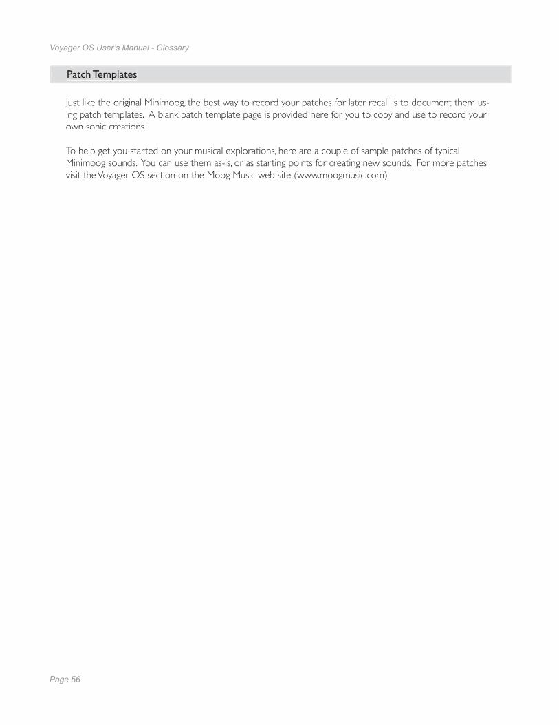
Page 56
Voyager OS User’s Manual - Glossary
Page 57
Voyager OS User’s Manual
Patch Templates
Just like the original Minimoog, the best way to record your patches for later recall is to document them us-ing patch templates. A blank patch template page is provided here for you to copy and use to record your own sonic creations.
To help get you started on your musical explorations, here are a couple of sample patches of typical Minimoog sounds. You can use them as-is, or as starting points for creating new sounds. For more patches, visit the Voyager OS section on the Moog Music web site (www.moogmusic.com).
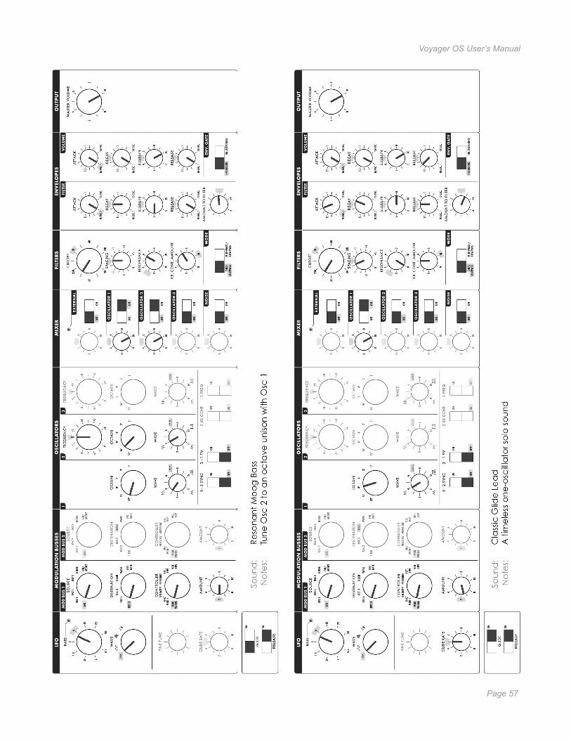
Page 56
Voyager OS User’s Manual - Glossary
Page 57
Voyager OS User’s Manual

Page 58
Voyager OS User’s Manual
Page 59
Voyager OS User’s Manual
Page 58
Voyager OS User’s Manual
Page 59
Voyager OS User’s Manual
Minimoog Voyager Old School User’s Manual© Moog Music 2008, all rights reserved
Text and illustrations by Greg Kist, Steve Dunningtonand the resources of Moog Music.