vowel synthesizer - mitvowel synthesizer 6.101 analog electronics lab - final project report jeremy...
TRANSCRIPT

Vowel Synthesizer 6.101 Analog Electronics Lab - Final Project Report
Jeremy Sogo and David Owusu-Antwi
May 17th, 2018

Table of Contents Abstract
Introduction
Voltage-Controlled Sinusoidal Oscillator
Harmonic Generator
Variable Gain Adder
Audio Amplifier
Control Circuitry
Arduino Code
Final Summary
Abstract - Jeremy and David
For our 6.101 final project, we propose building a vowel synthesizer. The device can generate sounds with voltage-controlled oscillators that resemble sounds of human speech. Vowel sounds can be synthesized with a few frequencies summed together. Initially, we will develop a system to produce one vowel sound at a particular frequency as a proof of concept. From there, we will expand it to make other vowel sounds and a circuit to control the pitch and other properties of the sound produced. If time permits, we can investigate the use of noise generators and other devices to generate consonant sounds, which are much more complex in the frequency spectrum. The components of our speech synthesizer include a frequency generator stage consisting of voltage-controlled oscillators to generate different frequency waveforms, a frequency mixer to add them in specific ratios, a speech output subsystem, and a control subsystem. The control subsystem involves using an Arduino to send control signals and manage timing to string sounds together into words and phrases. Selecting the amplitude ratios for the harmonics required to produce a vowel sound did not produce a clearly distinguishable vowel sound. The result of implementing our circuit design was being able to selectively synthesize sounds of varying audible frequencies. With the control subsystem, we can store and play back a bank of sounds and set a specific playtime for each sound.

Introduction - David
The goal of this project is to synthesize distinguishable vowel sounds. The difficulty arises in fine-tuning the synthesized waveform to sound like human speech. Every sound has a representative waveform that can be synthesized by summing sinusoids of different frequencies and different amplitudes. For a sinusoid with a given frequency, referred to as the fundamental frequency, its harmonics have integer multiples of the fundamental frequency. Any arbitrary periodic waveform can be decomposed into a Fourier series, a sum of harmonics. By taking the Fourier transform of a sound wave to produce an amplitude spectrum, as in Figure 1, the relative magnitudes of harmonics present in the waveform can be retrieved. The relative amplitudes of harmonics in the synthesized vowel sound need to be specific in order to sound like human speech.
Figure 1
Taking the Fourier transform of a speech waveform as in Figure 1 shows that its fundamental frequency is in fact an octave below the frequency heard. In Figure 1, the

frequency heard is at 440Hz, but the fundamental frequency (also known as the first harmonic) is seen to be at 220Hz. This might be particular to human speech, and can be explored by looking at the amplitude spectrums of other kinds of sounds (e.g. from musical instruments or other human sounds like humming). An amplitude spectrum will show harmonics present in a sound wave. In synthesizing a waveform, the most important harmonics are those with the largest relative magnitudes. Also, the more harmonics that are included, the closer to the original sound the waveform gets. The way a sound is perceived depends on the properties of its waveform. The number of harmonics included affect the quality of the synthesized sound, and the presence of real-time amplitude variation can produce vibrato.
Figure 2
The frequency generator is implemented with a modified Wien Bridge oscillator involving a positive gain amplifier. The generated fundamental frequency sine wave will then be fed into a multiplier as two inputs to generate a harmonic, and by subsequently feeding in the fundamental and generated harmonics, more harmonics can be generated. The frequency mixer will mix together harmonics with a variable gain adder, using an op-amp adder stage with JFETs as variable resistors. An additional Wien Bridge oscillator will add vibrato to the final synthesized waveform, which will then be output with a Class AB audio amplifier.
Voltage-Controlled Sinusoidal Oscillator - Jeremy
For Fourier additive synthesis, a clean, fundamental sine wave is required as a
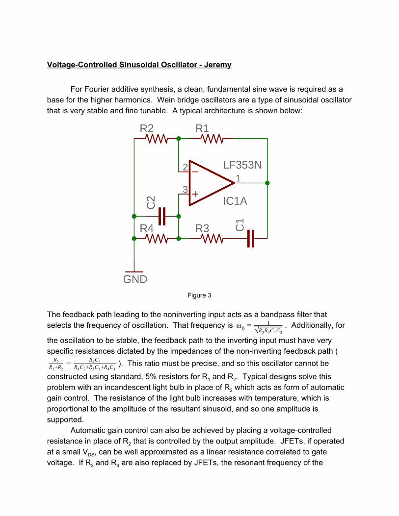
base for the higher harmonics. Wein bridge oscillators are a type of sinusoidal oscillator that is very stable and fine tunable. A typical architecture is shown below:
Figure 3
The feedback path leading to the noninverting input acts as a bandpass filter that selects the frequency of oscillation. That frequency is . Additionally, forω0 =
1√R R C C3 4 1 2
the oscillation to be stable, the feedback path to the inverting input must have very specific resistances dictated by the impedances of the non-inverting feedback path (
). This ratio must be precise, and so this oscillator cannot beR2R +R1 2
= R C4 1R C +R C +R C4 2 3 1 4 1
constructed using standard, 5% resistors for R1 and R2. Typical designs solve this problem with an incandescent light bulb in place of R2 which acts as form of automatic gain control. The resistance of the light bulb increases with temperature, which is proportional to the amplitude of the resultant sinusoid, and so one amplitude is supported.
Automatic gain control can also be achieved by placing a voltage-controlled resistance in place of R2 that is controlled by the output amplitude. JFETs, if operated at a small VDS, can be well approximated as a linear resistance correlated to gate voltage. If R3 and R4 are also replaced by JFETs, the resonant frequency of the
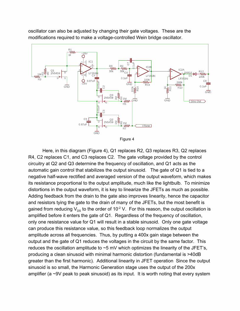
oscillator can also be adjusted by changing their gate voltages. These are the modifications required to make a voltage-controlled Wein bridge oscillator.
Figure 4
Here, in this diagram (Figure 4), Q1 replaces R2, Q3 replaces R3, Q2 replaces
R4, C2 replaces C1, and C3 replaces C2. The gate voltage provided by the control circuitry at Q2 and Q3 determine the frequency of oscillation, and Q1 acts as the automatic gain control that stabilizes the output sinusoid. The gate of Q1 is tied to a negative half-wave rectified and averaged version of the output waveform, which makes its resistance proportional to the output amplitude, much like the lightbulb. To minimize distortions in the output waveform, it is key to linearize the JFETs as much as possible. Adding feedback from the drain to the gate also improves linearity, hence the capacitor and resistors tying the gate to the drain of many of the JFETs, but the most benefit is gained from reducing VDS to the order of 10-2 V. For this reason, the output oscillation is amplified before it enters the gate of Q1. Regardless of the frequency of oscillation, only one resistance value for Q1 will result in a stable sinusoid. Only one gate voltage can produce this resistance value, so this feedback loop normalizes the output amplitude across all frequencies. Thus, by putting a 400x gain stage between the output and the gate of Q1 reduces the voltages in the circuit by the same factor. This reduces the oscillation amplitude to ~5 mV which optimizes the linearity of the JFET’s, producing a clean sinusoid with minimal harmonic distortion (fundamental is >40dB greater than the first harmonic). Additional linearity in JFET operation Since the output sinusoid is so small, the Harmonic Generation stage uses the output of the 200x amplifier (a ~9V peak to peak sinusoid) as its input. It is worth noting that every system

will be operate differently based upon the pinch-off voltage of the JFET’s used. If possible, it is recommended that Q2 and Q3 have as similar pinch-off voltages as possible to minimize distortions and output amplitude changes. For this particular system, the output amplitude is the same for all frequencies from 60Hz to 1kHz The Sallen-Key filter is placed before the gain stage further attenuates the higher harmonics of the sinusoidal output for an even cleaner sine wave.

Harmonic Generator - Jeremy
The harmonics of the fundamental are generated through the multiplication of
sinusoids. The product of two sinusoids can be expressed as a sum of two sinusoids, one with a frequency of the difference of the frequencies of the original sinusoids, and one with a frequency that is the sum of the aforementioned frequencies. The precise equation is shown below.
in(αt)sin(βt)s = 21 (cos os )((α ) )+ β t + c ((α ) )− β t
To generate integer multiples of the fundamental frequency, the first harmonic, a series of multiplications are used. The product of the fundamental frequency input with itself produces a sinusoid of twice the frequency with a DC offset. The second harmonic output is this output passed through a high-pass filter to remove the DC component. The product of the first harmonic with the negative fundamental produces a wave that is the sum of a sinusoid with 1x the frequency, and 3x the frequency. By adding back the fundamental frequency with a tuned potentiometer, the third harmonic can be extracted. The fourth harmonic is generated much like the second, except it uses the first harmonic instead of the fundamental as the multiplicands, and is high-pass filtered as before. A similar principle to the third applies to the fifth harmonic. The fourth harmonic is multiplied by the negative fundamental, and the third harmonic is added back to isolate the fifth harmonic.
There is a phase shift introduced by some of the multiplications. If the first harmonic is a sine wave, the second harmonic will be a cosine wave. The product of the first and second harmonics produces two sine waves again, so simple subtraction can be used to eliminate the first harmonic from the product. The fourth harmonic is the product of two cosine curves, and so itself is a cosine curve. The product of the fourth and first harmonic becomes a sine wave again and so, like the third harmonic, the fifth harmonic can be extracted by subtracting the third harmonic.

Figure 5
This can be implemented in circuitry using multipliers. AD633 is such an IC that
takes five inputs and outputs the function below: Q = 1
10V ((X1 2) )− X (Y 1 2)− Y + Z By grounding one of the X inputs and one of the Y inputs, the output becomes
the product of the two remaining inputs. Also, by inputting a fraction of Q into Z, the coefficient (i.e. the ) can be increased. This is done to keep the output amplitude of1
10V the sinusoids high. It does not particularly matter what those voltages are (as long as they do not exceed the rail voltages), but it is important to normalize the output voltages

to a small value (i.e. ~30mV) to ensure the variable gain adder operates as linearly as possible.
There are three potentiometers that must be tuned for proper circuit operation. R5 adds some of the second harmonic into the first harmonic to reduce distortions in the second harmonic and, consequently, all other harmonics down the line. R15 and R25 are tuned to remove the first and third harmonics respectively present in the products of multiplications of the input sine waves. This tuning cannot be done with standard resistors as the ratio must be exact for optimal harmonic purity. Even a 5% difference will noticeably distort the sine waves.
The choices of resistances here are chosen for the particular system this team built. Any changes in JFETs will require different resistances and dividers. Any system, once fixed resistance values have been chosen, will remain consistent in operation. This is not the case for the potentiometers. Since their value must be much more precise than the others, any small change in device operation due to temperature will require retuning the potentiometers. This can be worked around if the operator has sufficient time to wait and has no qualms with wasting power. If the system is left running, its temperature does find a decently consistent equilibrium temperature while in a climate-controlled room. If the potentiometers are tuned for that equilibrium temperature, the same device operation can be replicated after the system warms up.
The benefit of using multipliers over other means of generating the higher harmonics is that of harmony. Using multipliers guarantees the higher harmonics will be perfectly in tune. The ear can detect harmonics that are even slightly off key, and so it is important to have a system that will always be in tune. While the output amplitude of multipliers may change with temperature, the frequencies remain true and exact. Even if the frequency of the oscillator changes, the higher harmonics will still be in perfect harmony with the first.

Variable Gain Adder - Jeremy
Figure 6
To generate different sounds, the harmonics must be added together in arbitrary ratios. Each harmonic is passed through a variable-gain amplifier that can provide a gain of 0 to ~50 based upon the gate voltage provided by the control circuitry. Again, JFET’s are
used as voltage-controlled resistances. The JFET’s here are chosen to have a similar threshold voltage so that the same control circuitry can be used for each JFET. The output stage of the harmonic generator attenuates and buffers the harmonics to normalized, 15mV peak to peak sinusoids so that the voltage across the JFET’s is minimized (this is important for linearity) and the same control voltage produces a similar gain. After each individual frequency is amplified to the desired magnitude, the harmonics are summed together and outputted to the audio amplifier. The relative phase of each harmonic is irrelevant to the ear; humans can detect only frequency and intensity of sound waves.

Audio Amplifier - David
The final synthesized sound wave is output with a Class AB audio amplifier. The amplifier consists of an Op-Amp amplifier stage and an output stage. The Op-Amp amplifier is an inverting amplifier with a voltage gain of about 9 (R5/R1 = 82K/9.1K ~ 9). The output stage consists of a common emitter amplifier using an NPN BJT in series with a common emitter amplifier using a PNP BJT. The base resistances of 3.9kΩ were selected in order to stabilize the output stage current, in addition to selecting BJTs with similar current gain (β) values. While the β values for the NPN and the PNP BJTs (145 and 198 respectively) were not identical, they were close enough to stabilize the output stage current.
Figure 7
For the inverting amplifier, the input capacitor was selected to be a large electrolytic capacitor, at about 1uF. Selecting a capacitor that was too large would lead to the capacitor storing a lot of charge and introducing a voltage offset into the amplifier. When sourcing the amplifier, the NPN BJT would burn out. The output stage also eliminated crossover distortion using using two 1N914 diodes in series.

Control Circuitry - Jeremy
The control voltages for the VCO and the harmonic synthesizer come from an
Arduino Nano.
This particular microcontroller has no analog outputs, but has six pulse-width modulation (PWM) outputs (pins D3, 5, 6, 9, 10, 11. Also, the pins can output 0-5V, which is not the range desired to operate JFET’s (theshold voltage is around -2.3-3V). The analog voltages required to control the JFET’s is synthsized by summing the Arduino’s PWM output with a reference voltage (i.e. -15V) with an inverting, summing amplifier. A capacitor is added to average the PWM output into a DC voltage.
For the harmonic synthesizer, each of the five variable gain amplifiers requires one level shifting circuit as shown below:
Figure 8
This shifts the operating range of the gate voltage to -2.8-0.5 V. The lower end is beyond the threshold voltage for the JFET, and so pinches off the channel (very large resistance), and the higher end reaches saturation for the JFET. This gives the maximum dynamic range for the variable gain amplifiers.
For the VCO control voltage (VTune), an operating range of -2.3 to .3 V is desired. The oscillator becomes unstable if the the JFET’s reach the cutoff regime, as that corresponds to an effectively infinite resistance, and the output waveform begins to distort at high gate voltages, as the JFET becomes increasingly nonlinear. A level shifter similar to the previous ones is at the beginning of the circuit below to produce the proper DC control voltages.
An additional effect known as vibrato can be added at this stage. Vibrato is a small, oscillating change in frequency of a musical note. This effect is commonly used by singers and string instrumentalists to add more life to the tone. This effect can be
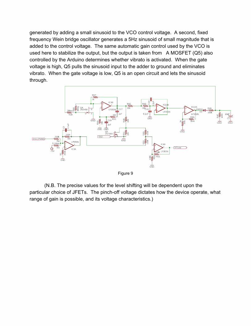
generated by adding a small sinusoid to the VCO control voltage. A second, fixed frequency Wein bridge oscillator generates a 5Hz sinusoid of small magnitude that is added to the control voltage. The same automatic gain control used by the VCO is used here to stabilize the output, but the output is taken from A MOSFET (Q5) also controlled by the Arduino determines whether vibrato is activated. When the gate voltage is high, Q5 pulls the sinusoid input to the adder to ground and eliminates vibrato. When the gate voltage is low, Q5 is an open circuit and lets the sinusoid through.
Figure 9
(N.B. The precise values for the level shifting will be dependent upon the
particular choice of JFETs. The pinch-off voltage dictates how the device operate, what range of gain is possible, and its voltage characteristics.)

Arduino Code
The Arduino Nano gets its power (+5V) and instructions from a computer. Using serial communication, the computer can set the fundamental frequency, magnitude of each harmonic, and the presence of vibrato. One of the benefits of using a microcontroller is the ability to program sequences and pitches can be controlled very precisely. In the range of JFET operation done here, there is an approximately linear relationship between PWM duty cycle (which corresponds to voltage) and the reciprocal of the resistance. This means the frequency of the VCO and the gain of the variable gain adder can be controlled by a linear scale.
A copy of the code can be found here: https://1drv.ms/u/s!AslX6lPUmvWYhNo4Jq8noQNiBNWbzw

Final Summary
This implementation does not produce clearly distinguishable vowel sounds, but the final synthesizer manages to produce distinct sounds, with a fundamental frequency range of 150-999Hz and amplitude range of 0-600mV for individual harmonics. The frequency generator stage consists of a single modified Wien Bridge oscillator, producing the sine wave used as the fundamental. Thus, a future design could add an additional oscillator at a slightly higher or lower frequency to It might be interesting to determine what behaviors other kinds of sounds show (e.g. musical instruments, other human-generated sounds like humming). Future research might consider whether changing the octave of synthesized speech preserves the waveform’s integrity, or how the perceived sound might be affected. This implementation only involved summing five harmonics (the fundamental plus four additional harmonics). While generating distinct sounds, a future implementation might consider adding many more harmonics in order to reproduce a sound as close to human speech as possible.