volume 2 - stormwater management for construction...
TRANSCRIPT

City of Tacoma 2016 SWMM
i Volume 2
Volume 2 - Stormwater Management for Construction Sites
Table of Contents
Purpose of this Volume. . . . . . . . . . . . . . . . . . . . . . . . . . . . . . . . . . . . . . . . . . . . . . . . . . . . . . . . . . . .2-1Content and Organization of this Volume . . . . . . . . . . . . . . . . . . . . . . . . . . . . . . . . . . . . . . . . . . . . . .2-1
Chapter 1 The 13 Elements of Construction Stormwater Pollution Prevention . . . . . . . . 2-3
Chapter 2 Developing a Construction Stormwater Pollution Prevention Plan (SWPPP) 2-152.1 General Requirements and Guidelines . . . . . . . . . . . . . . . . . . . . . . . . . . . . . . . . . . . . . . . . . . . .2-15
2.2 BMP Standards and Specifications. . . . . . . . . . . . . . . . . . . . . . . . . . . . . . . . . . . . . . . . . . . . . . .2-16
2.3 Step-by-Step Procedure . . . . . . . . . . . . . . . . . . . . . . . . . . . . . . . . . . . . . . . . . . . . . . . . . . . . . . .2-16
2.3.1 Step 1 – Data Collection . . . . . . . . . . . . . . . . . . . . . . . . . . . . . . . . . . . . . . . . . . . . . . . . . .2-16
2.3.2 Step 2 – Data Analysis . . . . . . . . . . . . . . . . . . . . . . . . . . . . . . . . . . . . . . . . . . . . . . . . . . .2-17
2.3.3 Step 3 – Construction SWPPP Development and Analysis . . . . . . . . . . . . . . . . . . . . . . .2-18
Chapter 3 Standards and Specifications for Best Management Practices (BMPs) . . . . . 2-253.1 Source Control BMPs . . . . . . . . . . . . . . . . . . . . . . . . . . . . . . . . . . . . . . . . . . . . . . . . . . . . . . . . .2-26
3.1.1 BMP C101: Preserving Natural Vegetation . . . . . . . . . . . . . . . . . . . . . . . . . . . . . . . . . . . .2-273.1.1.1 Purpose . . . . . . . . . . . . . . . . . . . . . . . . . . . . . . . . . . . . . . . . . . . . . . . . . . . . . . . . . .2-273.1.1.2 Conditions of Use. . . . . . . . . . . . . . . . . . . . . . . . . . . . . . . . . . . . . . . . . . . . . . . . . . .2-283.1.1.3 Design and Installation Specifications . . . . . . . . . . . . . . . . . . . . . . . . . . . . . . . . . . .2-283.1.1.4 Maintenance Standards . . . . . . . . . . . . . . . . . . . . . . . . . . . . . . . . . . . . . . . . . . . . . .2-28
3.1.2 BMP C102: Buffer Zone . . . . . . . . . . . . . . . . . . . . . . . . . . . . . . . . . . . . . . . . . . . . . . . . . .2-293.1.2.1 Purpose . . . . . . . . . . . . . . . . . . . . . . . . . . . . . . . . . . . . . . . . . . . . . . . . . . . . . . . . . .2-293.1.2.2 Conditions of Use. . . . . . . . . . . . . . . . . . . . . . . . . . . . . . . . . . . . . . . . . . . . . . . . . . .2-293.1.2.3 Design and Installation Specifications . . . . . . . . . . . . . . . . . . . . . . . . . . . . . . . . . . .2-293.1.2.4 Maintenance Standards . . . . . . . . . . . . . . . . . . . . . . . . . . . . . . . . . . . . . . . . . . . . . .2-29
3.1.3 BMP C103: High Visibility Fence. . . . . . . . . . . . . . . . . . . . . . . . . . . . . . . . . . . . . . . . . . . .2-303.1.3.1 Purpose . . . . . . . . . . . . . . . . . . . . . . . . . . . . . . . . . . . . . . . . . . . . . . . . . . . . . . . . . .2-303.1.3.2 Conditions of Use. . . . . . . . . . . . . . . . . . . . . . . . . . . . . . . . . . . . . . . . . . . . . . . . . . .2-303.1.3.3 Design and Installation Specifications . . . . . . . . . . . . . . . . . . . . . . . . . . . . . . . . . . .2-303.1.3.4 Maintenance Standards . . . . . . . . . . . . . . . . . . . . . . . . . . . . . . . . . . . . . . . . . . . . . .2-30
3.1.4 BMP C105: Stabilized Construction Entrance/Exit . . . . . . . . . . . . . . . . . . . . . . . . . . . . . .2-313.1.4.1 Purpose . . . . . . . . . . . . . . . . . . . . . . . . . . . . . . . . . . . . . . . . . . . . . . . . . . . . . . . . . .2-313.1.4.2 Conditions of Use. . . . . . . . . . . . . . . . . . . . . . . . . . . . . . . . . . . . . . . . . . . . . . . . . . .2-313.1.4.3 Design and Installation Specifications . . . . . . . . . . . . . . . . . . . . . . . . . . . . . . . . . . .2-313.1.4.4 Maintenance Standards . . . . . . . . . . . . . . . . . . . . . . . . . . . . . . . . . . . . . . . . . . . . . .2-31
3.1.5 BMP C106: Wheel Wash. . . . . . . . . . . . . . . . . . . . . . . . . . . . . . . . . . . . . . . . . . . . . . . . . .2-353.1.5.1 Purpose . . . . . . . . . . . . . . . . . . . . . . . . . . . . . . . . . . . . . . . . . . . . . . . . . . . . . . . . . .2-353.1.5.2 Conditions of Use. . . . . . . . . . . . . . . . . . . . . . . . . . . . . . . . . . . . . . . . . . . . . . . . . . .2-353.1.5.3 Design and Installation Specifications . . . . . . . . . . . . . . . . . . . . . . . . . . . . . . . . . . .2-353.1.5.4 Maintenance Standards . . . . . . . . . . . . . . . . . . . . . . . . . . . . . . . . . . . . . . . . . . . . . .2-35
3.1.6 BMP C107: Construction Road/Parking Area Stabilization . . . . . . . . . . . . . . . . . . . . . . . .2-373.1.6.1 Purpose . . . . . . . . . . . . . . . . . . . . . . . . . . . . . . . . . . . . . . . . . . . . . . . . . . . . . . . . . .2-373.1.6.2 Conditions of Use. . . . . . . . . . . . . . . . . . . . . . . . . . . . . . . . . . . . . . . . . . . . . . . . . . .2-373.1.6.3 Design and Installation Specifications . . . . . . . . . . . . . . . . . . . . . . . . . . . . . . . . . . .2-37

2016 SWMM City of Tacoma
Volume 2 ii
3.1.6.4 Maintenance Standards . . . . . . . . . . . . . . . . . . . . . . . . . . . . . . . . . . . . . . . . . . . . . .2-38
3.1.7 BMP C120: Temporary and Permanent Seeding . . . . . . . . . . . . . . . . . . . . . . . . . . . . . . .2-393.1.7.1 Purpose . . . . . . . . . . . . . . . . . . . . . . . . . . . . . . . . . . . . . . . . . . . . . . . . . . . . . . . . . .2-393.1.7.2 Conditions of Use. . . . . . . . . . . . . . . . . . . . . . . . . . . . . . . . . . . . . . . . . . . . . . . . . . .2-393.1.7.3 Design and Installation Specifications . . . . . . . . . . . . . . . . . . . . . . . . . . . . . . . . . . .2-393.1.7.4 Maintenance Standards . . . . . . . . . . . . . . . . . . . . . . . . . . . . . . . . . . . . . . . . . . . . . .2-41
3.1.8 BMP C121: Mulching . . . . . . . . . . . . . . . . . . . . . . . . . . . . . . . . . . . . . . . . . . . . . . . . . . . .2-443.1.8.1 Purpose . . . . . . . . . . . . . . . . . . . . . . . . . . . . . . . . . . . . . . . . . . . . . . . . . . . . . . . . . .2-443.1.8.2 Conditions of Use. . . . . . . . . . . . . . . . . . . . . . . . . . . . . . . . . . . . . . . . . . . . . . . . . . .2-443.1.8.3 Design and Installation Specifications . . . . . . . . . . . . . . . . . . . . . . . . . . . . . . . . . . .2-443.1.8.4 Maintenance Standards . . . . . . . . . . . . . . . . . . . . . . . . . . . . . . . . . . . . . . . . . . . . . .2-44
3.1.9 BMP C122: Nets and Blankets . . . . . . . . . . . . . . . . . . . . . . . . . . . . . . . . . . . . . . . . . . . . .2-483.1.9.1 Purpose . . . . . . . . . . . . . . . . . . . . . . . . . . . . . . . . . . . . . . . . . . . . . . . . . . . . . . . . . .2-483.1.9.2 Conditions of Use. . . . . . . . . . . . . . . . . . . . . . . . . . . . . . . . . . . . . . . . . . . . . . . . . . .2-483.1.9.3 Design and Installation Specifications . . . . . . . . . . . . . . . . . . . . . . . . . . . . . . . . . . .2-483.1.9.4 Maintenance Standards . . . . . . . . . . . . . . . . . . . . . . . . . . . . . . . . . . . . . . . . . . . . . .2-50
3.1.10 BMP C123: Plastic Covering . . . . . . . . . . . . . . . . . . . . . . . . . . . . . . . . . . . . . . . . . . . . . .2-533.1.10.1 Purpose . . . . . . . . . . . . . . . . . . . . . . . . . . . . . . . . . . . . . . . . . . . . . . . . . . . . . . . . .2-533.1.10.2 Conditions of Use. . . . . . . . . . . . . . . . . . . . . . . . . . . . . . . . . . . . . . . . . . . . . . . . . .2-533.1.10.3 Design and Installation Specifications . . . . . . . . . . . . . . . . . . . . . . . . . . . . . . . . . .2-533.1.10.4 Maintenance Standards . . . . . . . . . . . . . . . . . . . . . . . . . . . . . . . . . . . . . . . . . . . . .2-54
3.1.11 BMP C124: Sodding . . . . . . . . . . . . . . . . . . . . . . . . . . . . . . . . . . . . . . . . . . . . . . . . . . . .2-563.1.11.1 Purpose . . . . . . . . . . . . . . . . . . . . . . . . . . . . . . . . . . . . . . . . . . . . . . . . . . . . . . . . .2-563.1.11.2 Conditions of Use. . . . . . . . . . . . . . . . . . . . . . . . . . . . . . . . . . . . . . . . . . . . . . . . . .2-563.1.11.3 Design and Installation Specifications . . . . . . . . . . . . . . . . . . . . . . . . . . . . . . . . . .2-563.1.11.4 Maintenance Standards . . . . . . . . . . . . . . . . . . . . . . . . . . . . . . . . . . . . . . . . . . . . .2-57
3.1.12 BMP C125: Compost. . . . . . . . . . . . . . . . . . . . . . . . . . . . . . . . . . . . . . . . . . . . . . . . . . . .2-583.1.12.1 Purpose . . . . . . . . . . . . . . . . . . . . . . . . . . . . . . . . . . . . . . . . . . . . . . . . . . . . . . . . .2-583.1.12.2 Conditions of Use. . . . . . . . . . . . . . . . . . . . . . . . . . . . . . . . . . . . . . . . . . . . . . . . . .2-583.1.12.3 Design and Installation Specifications . . . . . . . . . . . . . . . . . . . . . . . . . . . . . . . . . .2-583.1.12.4 Maintenance Standards . . . . . . . . . . . . . . . . . . . . . . . . . . . . . . . . . . . . . . . . . . . .2-59
3.1.13 BMP C126: Topsoiling. . . . . . . . . . . . . . . . . . . . . . . . . . . . . . . . . . . . . . . . . . . . . . . . . . .2-603.1.13.1 Purpose . . . . . . . . . . . . . . . . . . . . . . . . . . . . . . . . . . . . . . . . . . . . . . . . . . . . . . . . .2-603.1.13.2 Conditions of Use. . . . . . . . . . . . . . . . . . . . . . . . . . . . . . . . . . . . . . . . . . . . . . . . . .2-603.1.13.3 Design and Installation Specifications . . . . . . . . . . . . . . . . . . . . . . . . . . . . . . . . . .2-603.1.13.4 Maintenance Standards . . . . . . . . . . . . . . . . . . . . . . . . . . . . . . . . . . . . . . . . . . . . .2-62
3.1.14 BMP C127: Polyacrylamide for Soil Erosion Protection . . . . . . . . . . . . . . . . . . . . . . . . .2-633.1.14.1 Purpose . . . . . . . . . . . . . . . . . . . . . . . . . . . . . . . . . . . . . . . . . . . . . . . . . . . . . . . . .2-633.1.14.2 Conditions of Use. . . . . . . . . . . . . . . . . . . . . . . . . . . . . . . . . . . . . . . . . . . . . . . . . .2-633.1.14.3 Design and Installation Specifications . . . . . . . . . . . . . . . . . . . . . . . . . . . . . . . . . .2-633.1.14.4 Maintenance Standards . . . . . . . . . . . . . . . . . . . . . . . . . . . . . . . . . . . . . . . . . . . . .2-65
3.1.15 BMP C130: Surface Roughening . . . . . . . . . . . . . . . . . . . . . . . . . . . . . . . . . . . . . . . . . .2-663.1.15.1 Purpose . . . . . . . . . . . . . . . . . . . . . . . . . . . . . . . . . . . . . . . . . . . . . . . . . . . . . . . . .2-663.1.15.2 Conditions for Use . . . . . . . . . . . . . . . . . . . . . . . . . . . . . . . . . . . . . . . . . . . . . . . . .2-663.1.15.3 Design and Installation Specifications . . . . . . . . . . . . . . . . . . . . . . . . . . . . . . . . . .2-663.1.15.4 Maintenance Standards . . . . . . . . . . . . . . . . . . . . . . . . . . . . . . . . . . . . . . . . . . . . .2-66
3.1.16 BMP C131: Gradient Terraces . . . . . . . . . . . . . . . . . . . . . . . . . . . . . . . . . . . . . . . . . . . .2-683.1.16.1 Purpose . . . . . . . . . . . . . . . . . . . . . . . . . . . . . . . . . . . . . . . . . . . . . . . . . . . . . . . . .2-683.1.16.2 Conditions of Use. . . . . . . . . . . . . . . . . . . . . . . . . . . . . . . . . . . . . . . . . . . . . . . . . .2-683.1.16.3 Design and Installation Specifications . . . . . . . . . . . . . . . . . . . . . . . . . . . . . . . . . .2-683.1.16.4 Maintenance Standards . . . . . . . . . . . . . . . . . . . . . . . . . . . . . . . . . . . . . . . . . . . . .2-69
3.1.17 BMP C140: Dust Control . . . . . . . . . . . . . . . . . . . . . . . . . . . . . . . . . . . . . . . . . . . . . . . .2-70

City of Tacoma 2016 SWMM
iii Volume 2
3.1.17.1 Purpose . . . . . . . . . . . . . . . . . . . . . . . . . . . . . . . . . . . . . . . . . . . . . . . . . . . . . . . . .2-703.1.17.2 Conditions of Use. . . . . . . . . . . . . . . . . . . . . . . . . . . . . . . . . . . . . . . . . . . . . . . . . .2-703.1.17.3 Design and Installation Specifications . . . . . . . . . . . . . . . . . . . . . . . . . . . . . . . . . .2-703.1.17.4 Maintenance Standards . . . . . . . . . . . . . . . . . . . . . . . . . . . . . . . . . . . . . . . . . . . . .2-71
3.1.18 BMP C150: Materials On Hand . . . . . . . . . . . . . . . . . . . . . . . . . . . . . . . . . . . . . . . . . . . .2-723.1.18.1 Purpose . . . . . . . . . . . . . . . . . . . . . . . . . . . . . . . . . . . . . . . . . . . . . . . . . . . . . . . . .2-723.1.18.2 Conditions of Use. . . . . . . . . . . . . . . . . . . . . . . . . . . . . . . . . . . . . . . . . . . . . . . . . .2-723.1.18.3 Design and Installation Specifications . . . . . . . . . . . . . . . . . . . . . . . . . . . . . . . . . .2-723.1.18.4 Maintenance Standards . . . . . . . . . . . . . . . . . . . . . . . . . . . . . . . . . . . . . . . . . . . .2-72
3.1.19 BMP C151: Concrete Handling . . . . . . . . . . . . . . . . . . . . . . . . . . . . . . . . . . . . . . . . . . . .2-733.1.19.1 Purpose . . . . . . . . . . . . . . . . . . . . . . . . . . . . . . . . . . . . . . . . . . . . . . . . . . . . . . . . .2-733.1.19.2 Conditions of Use. . . . . . . . . . . . . . . . . . . . . . . . . . . . . . . . . . . . . . . . . . . . . . . . . .2-733.1.19.3 Design and Installation Specifications . . . . . . . . . . . . . . . . . . . . . . . . . . . . . . . . . .2-733.1.19.4 Maintenance Standards . . . . . . . . . . . . . . . . . . . . . . . . . . . . . . . . . . . . . . . . . . . . .2-74
3.1.20 BMP C152: Sawcutting and Surfacing Pollution Prevention . . . . . . . . . . . . . . . . . . . . . .2-753.1.20.1 Purpose . . . . . . . . . . . . . . . . . . . . . . . . . . . . . . . . . . . . . . . . . . . . . . . . . . . . . . . . .2-753.1.20.2 Conditions of Use. . . . . . . . . . . . . . . . . . . . . . . . . . . . . . . . . . . . . . . . . . . . . . . . . .2-753.1.20.3 Design and Installation Specifications . . . . . . . . . . . . . . . . . . . . . . . . . . . . . . . . . .2-753.1.20.4 Maintenance Standards . . . . . . . . . . . . . . . . . . . . . . . . . . . . . . . . . . . . . . . . . . . . .2-75
3.1.21 BMP C153: Material Delivery, Storage and Containment . . . . . . . . . . . . . . . . . . . . . . . .2-763.1.21.1 Purpose . . . . . . . . . . . . . . . . . . . . . . . . . . . . . . . . . . . . . . . . . . . . . . . . . . . . . . . . .2-763.1.21.2 Conditions of Use. . . . . . . . . . . . . . . . . . . . . . . . . . . . . . . . . . . . . . . . . . . . . . . . . .2-763.1.21.3 Design and Installation Specifications . . . . . . . . . . . . . . . . . . . . . . . . . . . . . . . . . .2-763.1.21.4 Material Storage Areas and Secondary Containment Practices: . . . . . . . . . . . . . .2-773.1.21.5 Maintenance. . . . . . . . . . . . . . . . . . . . . . . . . . . . . . . . . . . . . . . . . . . . . . . . . . . . . .2-77
3.1.22 BMP C154: Concrete Washout Area. . . . . . . . . . . . . . . . . . . . . . . . . . . . . . . . . . . . . . . .2-783.1.22.1 Purpose . . . . . . . . . . . . . . . . . . . . . . . . . . . . . . . . . . . . . . . . . . . . . . . . . . . . . . . . .2-783.1.22.2 Conditions of Use. . . . . . . . . . . . . . . . . . . . . . . . . . . . . . . . . . . . . . . . . . . . . . . . . .2-783.1.22.3 Implementation. . . . . . . . . . . . . . . . . . . . . . . . . . . . . . . . . . . . . . . . . . . . . . . . . . . .2-783.1.22.4 Education . . . . . . . . . . . . . . . . . . . . . . . . . . . . . . . . . . . . . . . . . . . . . . . . . . . . . . . .2-783.1.22.5 Location and Placement Considerations: . . . . . . . . . . . . . . . . . . . . . . . . . . . . . . .2-793.1.22.6 Onsite Temporary Concrete Washout Facility, Transit Truck Washout Procedures:. .
2-793.1.22.7 Inspection and Maintenance . . . . . . . . . . . . . . . . . . . . . . . . . . . . . . . . . . . . . . . . .2-803.1.22.8 Removal of Temporary Concrete Washout Facilities. . . . . . . . . . . . . . . . . . . . . . .2-81
3.1.23 BMP C160: Erosion and Sediment Control Lead . . . . . . . . . . . . . . . . . . . . . . . . . . . . . .2-843.1.23.1 Purpose . . . . . . . . . . . . . . . . . . . . . . . . . . . . . . . . . . . . . . . . . . . . . . . . . . . . . . . . .2-843.1.23.2 Conditions of Use. . . . . . . . . . . . . . . . . . . . . . . . . . . . . . . . . . . . . . . . . . . . . . . . . .2-843.1.23.3 Specifications . . . . . . . . . . . . . . . . . . . . . . . . . . . . . . . . . . . . . . . . . . . . . . . . . . . . .2-84
3.1.24 BMP C161: Payment of Erosion Control Work . . . . . . . . . . . . . . . . . . . . . . . . . . . . . . . .2-863.1.24.1 Purpose . . . . . . . . . . . . . . . . . . . . . . . . . . . . . . . . . . . . . . . . . . . . . . . . . . . . . . . . .2-86
3.1.25 BMP C162: Scheduling . . . . . . . . . . . . . . . . . . . . . . . . . . . . . . . . . . . . . . . . . . . . . . . . . .2-873.1.25.1 Purpose . . . . . . . . . . . . . . . . . . . . . . . . . . . . . . . . . . . . . . . . . . . . . . . . . . . . . . . . .2-873.1.25.2 Conditions of Use. . . . . . . . . . . . . . . . . . . . . . . . . . . . . . . . . . . . . . . . . . . . . . . . . .2-873.1.25.3 Design Considerations . . . . . . . . . . . . . . . . . . . . . . . . . . . . . . . . . . . . . . . . . . . . . .2-87
3.2 Runoff, Conveyance and Treatment BMPs. . . . . . . . . . . . . . . . . . . . . . . . . . . . . . . . . . . . . . . . .2-88
3.2.1 BMP C200: Interceptor Dike and Swale . . . . . . . . . . . . . . . . . . . . . . . . . . . . . . . . . . . . . .2-893.2.1.1 Purpose . . . . . . . . . . . . . . . . . . . . . . . . . . . . . . . . . . . . . . . . . . . . . . . . . . . . . . . . . .2-893.2.1.2 Conditions of Use. . . . . . . . . . . . . . . . . . . . . . . . . . . . . . . . . . . . . . . . . . . . . . . . . . .2-903.2.1.3 Design and Installation Specifications . . . . . . . . . . . . . . . . . . . . . . . . . . . . . . . . . . .2-90
3.2.2 BMP C201: Grass-Lined Channels . . . . . . . . . . . . . . . . . . . . . . . . . . . . . . . . . . . . . . . . . .2-923.2.2.1 Purpose . . . . . . . . . . . . . . . . . . . . . . . . . . . . . . . . . . . . . . . . . . . . . . . . . . . . . . . . . .2-92

2016 SWMM City of Tacoma
Volume 2 iv
3.2.2.2 Conditions of Use. . . . . . . . . . . . . . . . . . . . . . . . . . . . . . . . . . . . . . . . . . . . . . . . . . .2-923.2.2.3 Design and Installation Specifications . . . . . . . . . . . . . . . . . . . . . . . . . . . . . . . . . . .2-923.2.2.4 Maintenance Standards . . . . . . . . . . . . . . . . . . . . . . . . . . . . . . . . . . . . . . . . . . . . . .2-93
3.2.3 BMP C202: Channel Lining . . . . . . . . . . . . . . . . . . . . . . . . . . . . . . . . . . . . . . . . . . . . . . . .2-963.2.3.1 Purpose . . . . . . . . . . . . . . . . . . . . . . . . . . . . . . . . . . . . . . . . . . . . . . . . . . . . . . . . . .2-963.2.3.2 Conditions of Use. . . . . . . . . . . . . . . . . . . . . . . . . . . . . . . . . . . . . . . . . . . . . . . . . . .2-963.2.3.3 Design and Installation Specifications . . . . . . . . . . . . . . . . . . . . . . . . . . . . . . . . . . .2-96
3.2.4 BMP C203: Water Bars . . . . . . . . . . . . . . . . . . . . . . . . . . . . . . . . . . . . . . . . . . . . . . . . . .2-983.2.4.1 Purpose . . . . . . . . . . . . . . . . . . . . . . . . . . . . . . . . . . . . . . . . . . . . . . . . . . . . . . . . . .2-983.2.4.2 Conditions of Use. . . . . . . . . . . . . . . . . . . . . . . . . . . . . . . . . . . . . . . . . . . . . . . . . . .2-983.2.4.3 Design and Installation Specifications . . . . . . . . . . . . . . . . . . . . . . . . . . . . . . . . . . .2-983.2.4.4 Maintenance Standards . . . . . . . . . . . . . . . . . . . . . . . . . . . . . . . . . . . . . . . . . . . . .2-99
3.2.5 BMP C204: Pipe Slope Drains . . . . . . . . . . . . . . . . . . . . . . . . . . . . . . . . . . . . . . . . . . . .2-1003.2.5.1 Purpose . . . . . . . . . . . . . . . . . . . . . . . . . . . . . . . . . . . . . . . . . . . . . . . . . . . . . . . . .2-1003.2.5.2 Conditions of Use. . . . . . . . . . . . . . . . . . . . . . . . . . . . . . . . . . . . . . . . . . . . . . . . . .2-1003.2.5.3 Design and Installation Specifications . . . . . . . . . . . . . . . . . . . . . . . . . . . . . . . . . .2-1003.2.5.4 Maintenance Standards . . . . . . . . . . . . . . . . . . . . . . . . . . . . . . . . . . . . . . . . . . . . .2-101
3.2.6 BMP C205: Subsurface Drains . . . . . . . . . . . . . . . . . . . . . . . . . . . . . . . . . . . . . . . . . . . .2-1033.2.6.1 Purpose . . . . . . . . . . . . . . . . . . . . . . . . . . . . . . . . . . . . . . . . . . . . . . . . . . . . . . . . .2-1033.2.6.2 Conditions of Use. . . . . . . . . . . . . . . . . . . . . . . . . . . . . . . . . . . . . . . . . . . . . . . . . .2-1033.2.6.3 Design and Installation Specifications . . . . . . . . . . . . . . . . . . . . . . . . . . . . . . . . . .2-1033.2.6.4 Maintenance Standards . . . . . . . . . . . . . . . . . . . . . . . . . . . . . . . . . . . . . . . . . . . . .2-104
3.2.7 BMP C206: Level Spreader. . . . . . . . . . . . . . . . . . . . . . . . . . . . . . . . . . . . . . . . . . . . . . .2-1053.2.7.1 Purpose . . . . . . . . . . . . . . . . . . . . . . . . . . . . . . . . . . . . . . . . . . . . . . . . . . . . . . . . .2-1053.2.7.2 Conditions of Use. . . . . . . . . . . . . . . . . . . . . . . . . . . . . . . . . . . . . . . . . . . . . . . . . .2-1053.2.7.3 Design and Installation Specifications . . . . . . . . . . . . . . . . . . . . . . . . . . . . . . . . . .2-1053.2.7.4 Maintenance Standards . . . . . . . . . . . . . . . . . . . . . . . . . . . . . . . . . . . . . . . . . . . . .2-106
3.2.8 BMP C207: Check Dams. . . . . . . . . . . . . . . . . . . . . . . . . . . . . . . . . . . . . . . . . . . . . . . . .2-1073.2.8.1 Purpose . . . . . . . . . . . . . . . . . . . . . . . . . . . . . . . . . . . . . . . . . . . . . . . . . . . . . . . . .2-1073.2.8.2 Conditions of Use. . . . . . . . . . . . . . . . . . . . . . . . . . . . . . . . . . . . . . . . . . . . . . . . . .2-1073.2.8.3 Design and Installation Specifications . . . . . . . . . . . . . . . . . . . . . . . . . . . . . . . . . .2-1073.2.8.4 Maintenance Standards . . . . . . . . . . . . . . . . . . . . . . . . . . . . . . . . . . . . . . . . . . . . .2-108
3.2.9 BMP C208: Triangular Silt Dike (Geotextile-Encased Check Dam) . . . . . . . . . . . . . . . .2-1103.2.9.1 Purpose . . . . . . . . . . . . . . . . . . . . . . . . . . . . . . . . . . . . . . . . . . . . . . . . . . . . . . . . .2-1103.2.9.2 Conditions of Use. . . . . . . . . . . . . . . . . . . . . . . . . . . . . . . . . . . . . . . . . . . . . . . . . .2-1103.2.9.3 Design and Installation Specifications . . . . . . . . . . . . . . . . . . . . . . . . . . . . . . . . . .2-1103.2.9.4 Maintenance Standards . . . . . . . . . . . . . . . . . . . . . . . . . . . . . . . . . . . . . . . . . . . . .2-110
3.2.10 BMP C209: Outlet Protection . . . . . . . . . . . . . . . . . . . . . . . . . . . . . . . . . . . . . . . . . . . .2-1123.2.10.1 Purpose . . . . . . . . . . . . . . . . . . . . . . . . . . . . . . . . . . . . . . . . . . . . . . . . . . . . . . . .2-1123.2.10.2 Conditions of Use. . . . . . . . . . . . . . . . . . . . . . . . . . . . . . . . . . . . . . . . . . . . . . . . .2-1123.2.10.3 Design and Installation Specifications . . . . . . . . . . . . . . . . . . . . . . . . . . . . . . . . .2-1123.2.10.4 Maintenance Standards . . . . . . . . . . . . . . . . . . . . . . . . . . . . . . . . . . . . . . . . . . . .2-112
3.2.11 BMP C220: Storm Drain Inlet Protection . . . . . . . . . . . . . . . . . . . . . . . . . . . . . . . . . . . .2-1133.2.11.1 Purpose . . . . . . . . . . . . . . . . . . . . . . . . . . . . . . . . . . . . . . . . . . . . . . . . . . . . . . . .2-1133.2.11.2 Conditions of Use. . . . . . . . . . . . . . . . . . . . . . . . . . . . . . . . . . . . . . . . . . . . . . . . .2-1133.2.11.3 Design and Installation Specifications . . . . . . . . . . . . . . . . . . . . . . . . . . . . . . . . .2-1133.2.11.4 Maintenance Standards . . . . . . . . . . . . . . . . . . . . . . . . . . . . . . . . . . . . . . . . . . . .2-121
3.2.12 BMP C231: Brush Barrier . . . . . . . . . . . . . . . . . . . . . . . . . . . . . . . . . . . . . . . . . . . . . . .2-1233.2.12.1 Purpose . . . . . . . . . . . . . . . . . . . . . . . . . . . . . . . . . . . . . . . . . . . . . . . . . . . . . . . .2-1233.2.12.2 Conditions of Use. . . . . . . . . . . . . . . . . . . . . . . . . . . . . . . . . . . . . . . . . . . . . . . . .2-1233.2.12.3 Design and Installation Specifications . . . . . . . . . . . . . . . . . . . . . . . . . . . . . . . . .2-1233.2.12.4 Maintenance Standards . . . . . . . . . . . . . . . . . . . . . . . . . . . . . . . . . . . . . . . . . . . .2-123

City of Tacoma 2016 SWMM
v Volume 2
3.2.13 BMP C232: Gravel Filter Berm . . . . . . . . . . . . . . . . . . . . . . . . . . . . . . . . . . . . . . . . . . .2-1253.2.13.1 Purpose . . . . . . . . . . . . . . . . . . . . . . . . . . . . . . . . . . . . . . . . . . . . . . . . . . . . . . . .2-1253.2.13.2 Conditions of Use. . . . . . . . . . . . . . . . . . . . . . . . . . . . . . . . . . . . . . . . . . . . . . . . .2-1253.2.13.3 Design and Installation Specifications . . . . . . . . . . . . . . . . . . . . . . . . . . . . . . . . .2-1253.2.13.4 Maintenance Standards . . . . . . . . . . . . . . . . . . . . . . . . . . . . . . . . . . . . . . . . . . . .2-125
3.2.14 BMP C233: Silt Fence . . . . . . . . . . . . . . . . . . . . . . . . . . . . . . . . . . . . . . . . . . . . . . . . . .2-1263.2.14.1 Purpose . . . . . . . . . . . . . . . . . . . . . . . . . . . . . . . . . . . . . . . . . . . . . . . . . . . . . . . .2-1263.2.14.2 Conditions of Use. . . . . . . . . . . . . . . . . . . . . . . . . . . . . . . . . . . . . . . . . . . . . . . . .2-1263.2.14.3 Design and Installation Specifications . . . . . . . . . . . . . . . . . . . . . . . . . . . . . . . . .2-1263.2.14.4 Maintenance Standards . . . . . . . . . . . . . . . . . . . . . . . . . . . . . . . . . . . . . . . . . . . .2-129
3.2.15 BMP C234: Vegetated Strip . . . . . . . . . . . . . . . . . . . . . . . . . . . . . . . . . . . . . . . . . . . . .2-1323.2.15.1 Purpose . . . . . . . . . . . . . . . . . . . . . . . . . . . . . . . . . . . . . . . . . . . . . . . . . . . . . . . .2-1323.2.15.2 Conditions of Use. . . . . . . . . . . . . . . . . . . . . . . . . . . . . . . . . . . . . . . . . . . . . . . . .2-1323.2.15.3 Design and Installation Specifications . . . . . . . . . . . . . . . . . . . . . . . . . . . . . . . . .2-1323.2.15.4 Maintenance Standards . . . . . . . . . . . . . . . . . . . . . . . . . . . . . . . . . . . . . . . . . . . .2-132
3.2.16 BMP C235: Wattles . . . . . . . . . . . . . . . . . . . . . . . . . . . . . . . . . . . . . . . . . . . . . . . . . . . .2-1333.2.16.1 Purpose . . . . . . . . . . . . . . . . . . . . . . . . . . . . . . . . . . . . . . . . . . . . . . . . . . . . . . . .2-1333.2.16.2 Conditions of Use. . . . . . . . . . . . . . . . . . . . . . . . . . . . . . . . . . . . . . . . . . . . . . . . .2-1333.2.16.3 Design Criteria . . . . . . . . . . . . . . . . . . . . . . . . . . . . . . . . . . . . . . . . . . . . . . . . . . .2-1333.2.16.4 Maintenance Standards . . . . . . . . . . . . . . . . . . . . . . . . . . . . . . . . . . . . . . . . . . . .2-134
3.2.17 BMP C236: Vegetative Filtration . . . . . . . . . . . . . . . . . . . . . . . . . . . . . . . . . . . . . . . . . .2-1363.2.17.1 Purpose . . . . . . . . . . . . . . . . . . . . . . . . . . . . . . . . . . . . . . . . . . . . . . . . . . . . . . . .2-1363.2.17.2 Conditions of Use. . . . . . . . . . . . . . . . . . . . . . . . . . . . . . . . . . . . . . . . . . . . . . . . .2-1363.2.17.3 Design Criteria . . . . . . . . . . . . . . . . . . . . . . . . . . . . . . . . . . . . . . . . . . . . . . . . . . .2-1363.2.17.4 Maintenance Standards . . . . . . . . . . . . . . . . . . . . . . . . . . . . . . . . . . . . . . . . . . . .2-137
3.2.18 BMP C240: Sediment Trap . . . . . . . . . . . . . . . . . . . . . . . . . . . . . . . . . . . . . . . . . . . . . .2-1383.2.18.1 Purpose . . . . . . . . . . . . . . . . . . . . . . . . . . . . . . . . . . . . . . . . . . . . . . . . . . . . . . . .2-1383.2.18.2 Conditions of Use. . . . . . . . . . . . . . . . . . . . . . . . . . . . . . . . . . . . . . . . . . . . . . . . .2-1383.2.18.3 Design and Installation Specifications . . . . . . . . . . . . . . . . . . . . . . . . . . . . . . . . .2-1393.2.18.4 Maintenance Standards . . . . . . . . . . . . . . . . . . . . . . . . . . . . . . . . . . . . . . . . . . . .2-141
3.2.19 BMP C241: Temporary Sediment Pond . . . . . . . . . . . . . . . . . . . . . . . . . . . . . . . . . . . .2-1423.2.19.1 Purpose . . . . . . . . . . . . . . . . . . . . . . . . . . . . . . . . . . . . . . . . . . . . . . . . . . . . . . . .2-1423.2.19.2 Conditions of Use. . . . . . . . . . . . . . . . . . . . . . . . . . . . . . . . . . . . . . . . . . . . . . . . .2-1423.2.19.3 Design and Installation Specifications . . . . . . . . . . . . . . . . . . . . . . . . . . . . . . . . .2-1423.2.19.4 Maintenance Standards . . . . . . . . . . . . . . . . . . . . . . . . . . . . . . . . . . . . . . . . . . . .2-145
3.2.20 BMP C250: Construction Stormwater Chemical Treatment . . . . . . . . . . . . . . . . . . . . .2-1493.2.20.1 Purpose . . . . . . . . . . . . . . . . . . . . . . . . . . . . . . . . . . . . . . . . . . . . . . . . . . . . . . . .2-1493.2.20.2 Conditions of Use. . . . . . . . . . . . . . . . . . . . . . . . . . . . . . . . . . . . . . . . . . . . . . . . .2-1493.2.20.3 Design and Installation Specifications . . . . . . . . . . . . . . . . . . . . . . . . . . . . . . . . .2-1493.2.20.4 Monitoring . . . . . . . . . . . . . . . . . . . . . . . . . . . . . . . . . . . . . . . . . . . . . . . . . . . . . .2-154
3.2.21 BMP C251: Construction Stormwater Filtration . . . . . . . . . . . . . . . . . . . . . . . . . . . . . .2-1563.2.21.1 Purpose . . . . . . . . . . . . . . . . . . . . . . . . . . . . . . . . . . . . . . . . . . . . . . . . . . . . . . . .2-1563.2.21.2 Conditions of Use. . . . . . . . . . . . . . . . . . . . . . . . . . . . . . . . . . . . . . . . . . . . . . . . .2-1563.2.21.3 Background Information . . . . . . . . . . . . . . . . . . . . . . . . . . . . . . . . . . . . . . . . . . . .2-1563.2.21.4 Design and Installation Specifications . . . . . . . . . . . . . . . . . . . . . . . . . . . . . . . . .2-1563.2.21.5 Maintenance Standards . . . . . . . . . . . . . . . . . . . . . . . . . . . . . . . . . . . . . . . . . . . .2-159
3.2.22 BMP C252: High pH Neutralization using CO2 . . . . . . . . . . . . . . . . . . . . . . . . . . . . . . .2-1603.2.22.1 Description . . . . . . . . . . . . . . . . . . . . . . . . . . . . . . . . . . . . . . . . . . . . . . . . . . . . . .2-1603.2.22.2 Treatment Procedures . . . . . . . . . . . . . . . . . . . . . . . . . . . . . . . . . . . . . . . . . . . .2-1613.2.22.3 Safety and Materials Handling . . . . . . . . . . . . . . . . . . . . . . . . . . . . . . . . . . . . . . .2-1613.2.22.4 Operator Records. . . . . . . . . . . . . . . . . . . . . . . . . . . . . . . . . . . . . . . . . . . . . . . . .2-161
3.2.23 BMP C253: pH Control for High pH Water . . . . . . . . . . . . . . . . . . . . . . . . . . . . . . . . . .2-163

2016 SWMM City of Tacoma
Volume 2 vi
3.2.23.1 Description . . . . . . . . . . . . . . . . . . . . . . . . . . . . . . . . . . . . . . . . . . . . . . . . . . . . . .2-1633.2.23.2 Disposal Methods. . . . . . . . . . . . . . . . . . . . . . . . . . . . . . . . . . . . . . . . . . . . . . . . .2-163
Appendix A Standard Notes for Temporary Erosion and Sedimentation Control Plans . . . 2-165
Appendix B Construction SWPPP Short Form . . . . . . . . . . . . . . . . . . . . . . . . . . . . . . . . . 2-167

City of Tacoma 2016 SWMM
Purpose 2- 1 Volume 2
VOLUME
2Stormwater Management for Construction Sites
Purpose of this VolumeThis volume of the Stormwater Management Manual discusses stormwater impacts and controls associated with construction activities. It addresses the planning, design, and implementation of stormwater management activities prior to and during the construction phase of projects.
The purpose of this volume is to provide guidance to prevent construction activities from adversely impacting downstream resources and onsite stormwater flows. Prevention of soil erosion, capture of water-borne and air-borne sediment that has been unavoidably released from exposed soils, and protection of water quality from onsite pollutant sources are all readily achievable when the proper Best Management Practices (BMPs) are planned, installed, and properly maintained.
Content and Organization of this VolumeVolume 2 consists of three chapters and three appendices that address the preparation and implementation of Construction Stormwater Pollution Prevention Plans (SWPPPs).
Chapter 1 describes the 13 elements of stormwater pollution prevention.
Chapter 2 presents a step-by-step method for developing a Construction SWPPP. It encourages examination of all possible conditions that could reasonably affect a particular project’s stormwater control systems during the construction phase of the project.
Chapter 3 contains BMPs for construction stormwater control and site management. The first section of Chapter 3 contains BMPs for Source Control. The second section addresses runoff, conveyance, and treatment BMPs. Various combinations of these BMPs should be used in the Construction SWPPP to satisfy each of the 13 elements applying to the project.

2016 SWMM City of Tacoma
Volume 2 2- 2 Content & Organization
Appendix A provides standard notes that should be used on the project Stormwater Pollution Prevention Plan (SWPPP) and associated drawings.
Appendix B provides the criteria and guidelines for creating a SWPPP Short Form.

City of Tacoma 2016 SWMM
Chapter 1 2- 3 Volume 2
Chapter 1 The 13 Elements of Construction Stormwater Pollution Prevention
The 13 elements of construction stormwater pollution prevention cover the general water quality protection strategies of limiting site impacts, preventing erosion and sedimentation, and managing activities and sources. The applicant is required to address the following 13 elements in the construction stormwater pollution prevention plan (SWPPP). If an element is considered unnecessary, the Construction SWPPP must describe why that element is not needed.
The 13 elements are:
• Element 1 – Mark Clearing Limits
• Element 2 – Establish Construction Access
• Element 3 – Control Flow Rates
• Element 4 – Install Sediment Controls
• Element 5 – Stabilize Soils
• Element 6 – Protect Slopes
• Element 7 – Protect Drain Inlets
• Element 8 – Stabilize Channels and Outlets
• Element 9 – Control Pollutants
• Element 10 – Control Dewatering
• Element 11 – Maintain BMPs
• Element 12 – Manage the Project
• Element 13 – Protect BMPs
Element #1: Preserve Vegetation and Mark Clearing Limits
• Before beginning any land disturbing activities, including clearing and grading, clearly mark all clearing limits, sensitive areas and their buffers, and trees that are to be preserved within the construction area to prevent damage and offsite impacts. Mark clearing limits both in the field and on the plans.
• Retain the duff layer, native topsoil, and natural vegetation in an undisturbed state to the maximum extent practicable. If it is not practicable to retain the duff layer in place, it should be stockpiled onsite, covered to prevent erosion, and replaced immediately upon completion of the ground-disturbing activities.
• Plastic, metal, or fabric fence may be used to mark the clearing limits.
• Suggested BMPs (Refer to Chapter 3):
◦ BMP C101: Preserving Natural Vegetation
◦ BMP C102: Buffer Zones
◦ BMP C103: High Visibility Fence
◦ BMP C233: Silt Fence
2016 SWMM City of Tacoma
Volume 2 2- 4 Chapter 1
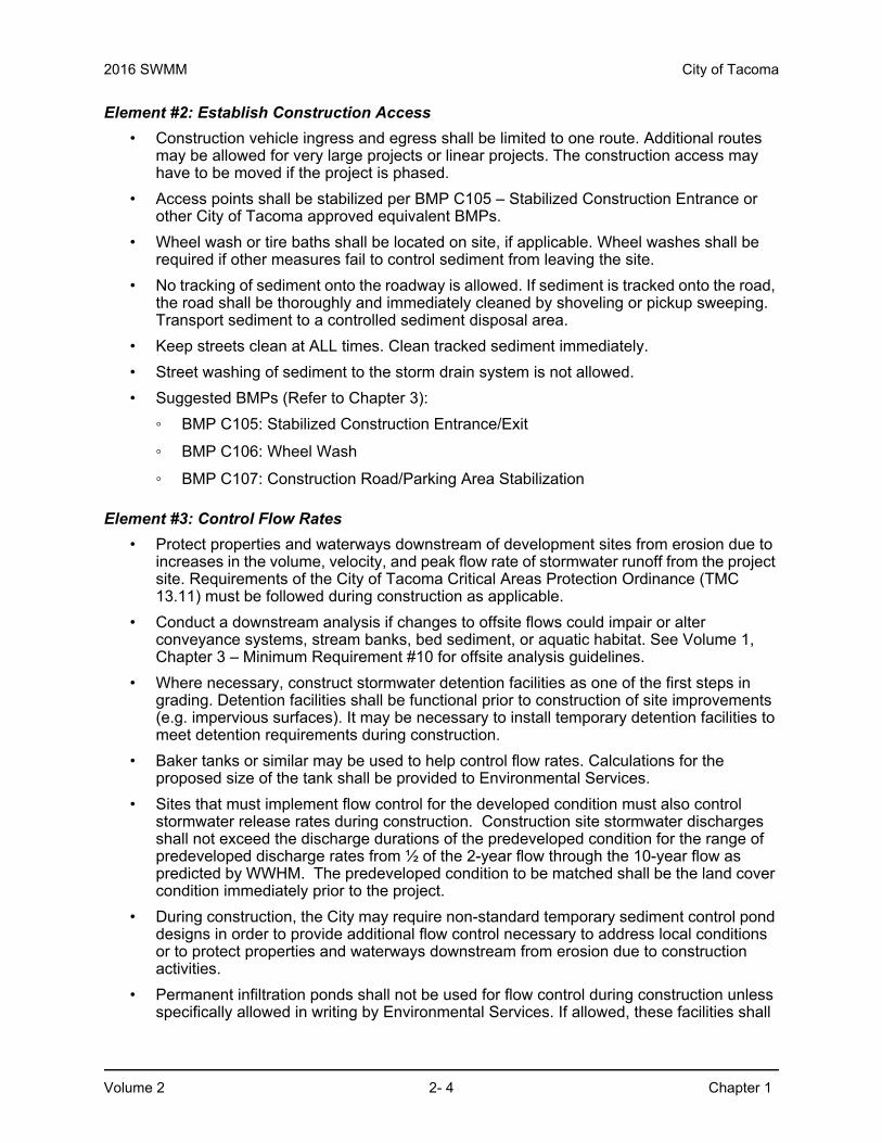
Element #2: Establish Construction Access
• Construction vehicle ingress and egress shall be limited to one route. Additional routes may be allowed for very large projects or linear projects. The construction access may have to be moved if the project is phased.
• Access points shall be stabilized per BMP C105 – Stabilized Construction Entrance or other City of Tacoma approved equivalent BMPs.
• Wheel wash or tire baths shall be located on site, if applicable. Wheel washes shall be required if other measures fail to control sediment from leaving the site.
• No tracking of sediment onto the roadway is allowed. If sediment is tracked onto the road, the road shall be thoroughly and immediately cleaned by shoveling or pickup sweeping. Transport sediment to a controlled sediment disposal area.
• Keep streets clean at ALL times. Clean tracked sediment immediately.
• Street washing of sediment to the storm drain system is not allowed.
• Suggested BMPs (Refer to Chapter 3):
◦ BMP C105: Stabilized Construction Entrance/Exit
◦ BMP C106: Wheel Wash
◦ BMP C107: Construction Road/Parking Area Stabilization
Element #3: Control Flow Rates
• Protect properties and waterways downstream of development sites from erosion due to increases in the volume, velocity, and peak flow rate of stormwater runoff from the project site. Requirements of the City of Tacoma Critical Areas Protection Ordinance (TMC 13.11) must be followed during construction as applicable.
• Conduct a downstream analysis if changes to offsite flows could impair or alter conveyance systems, stream banks, bed sediment, or aquatic habitat. See Volume 1, Chapter 3 – Minimum Requirement #10 for offsite analysis guidelines.
• Where necessary, construct stormwater detention facilities as one of the first steps in grading. Detention facilities shall be functional prior to construction of site improvements (e.g. impervious surfaces). It may be necessary to install temporary detention facilities to meet detention requirements during construction.
• Baker tanks or similar may be used to help control flow rates. Calculations for the proposed size of the tank shall be provided to Environmental Services.
• Sites that must implement flow control for the developed condition must also control stormwater release rates during construction. Construction site stormwater discharges shall not exceed the discharge durations of the predeveloped condition for the range of predeveloped discharge rates from ½ of the 2-year flow through the 10-year flow as predicted by WWHM. The predeveloped condition to be matched shall be the land cover condition immediately prior to the project.
• During construction, the City may require non-standard temporary sediment control pond designs in order to provide additional flow control necessary to address local conditions or to protect properties and waterways downstream from erosion due to construction activities.
• Permanent infiltration ponds shall not be used for flow control during construction unless specifically allowed in writing by Environmental Services. If allowed, these facilities shall

City of Tacoma 2016 SWMM
Chapter 1 2- 5 Volume 2
be protected from siltation during the construction phase as required by Environmental Services. A liner may be required. The ponds shall be excavated to final grade after the site is stabilized.
• Suggested BMPs (Refer to Chapter 3):
◦ BMP C240: Sediment Trap
◦ BMP C241: Temporary Sediment Pond
◦ BMP C203: Water Bars
◦ BMP C207: Check Dams
◦ BMP C209: Outlet Protection
◦ BMP C235: Wattles
Element #4: Install Sediment Controls
• Design, install, and maintain effective erosion controls and sediment control to minimize the discharge of pollutants.
• Minimize sediment discharges from the site. The design, installation and maintenance of erosion and sediment controls must address factors such as the amount, frequency, intensity and duration of precipitation, the nature of resulting stormwater runoff, and soil characteristics, including the range of soil particle sizes expected to be present on the site.
• Prior to leaving a construction site or prior to discharge to an infiltration facility, stormwater runoff from disturbed areas shall pass through a sediment pond or other appropriate sediment removal BMP.
• Construct sediment control BMPs as one of the first steps in grading. These BMPs shall be functional before other land disturbing activities take place.
• Locate BMPs in a manner to avoid interference with the movement of juvenile salmonids attempting to enter off-channel areas or drainages.
• Seed and mulch earthen structures such as dams, dikes, and diversions according to the timing indicated in Element #5.
• Design outlet structures to withdraw impounded stormwater from the surface to avoid discharging sediment that is still suspended lower in the water column. If installing a floating pump structure, include a stopper to prevent the pump basket from hitting the bottom of the pond.
• Full stabilization includes concrete or asphalt paving; quarry spalls used as ditch lining; or the use of rolled erosion products, a bonded fiber matrix product, or vegetative cover in a manner that will fully prevent soil erosion.
• Suggested BMPs (Refer to Chapter 3):
◦ BMP C231: Brush Barrier
◦ BMP C232: Gravel Filter Berm
◦ BMP C233: Silt Fence
◦ BMP C234: Vegetated Strip
◦ BMP C235: Wattles

2016 SWMM City of Tacoma
Volume 2 2- 6 Chapter 1
◦ BMP C240: Sediment Trap
◦ BMP C241: Temporary Sediment Pond
◦ BMP C250: Construction Stormwater Chemical Treatment
◦ BMP C251: Construction Stormwater Filtration
• Proprietary technologies exist that can be used for sediment control. The applicant can utilize any BMP that has been approved by Ecology via the Construction Technical Assessment Protocol Ecology program.
Element #5: Stabilize Soils
• Stabilize exposed and unworked soils by application of effective BMPs that protect the soil from the erosive forces of raindrop impact, flowing water, and wind.
• From October 1 through April 30, no soils shall remain exposed and unworked for more than 2 days. From May 1 to September 30, no soils shall remain exposed and unworked for more than 7 days. This stabilization requirement applies to all soils on site, whether at final grade or not.
• Stabilize soils at the end of the shift, before a holiday or weekend, if needed, based on the weather forecast.
• Select appropriate soil stabilization measures for the time of year, site conditions, estimated duration of use, and the potential water quality impacts that stabilization agents may have on downstream waters or groundwater.
• Stabilize soil stockpiles from erosion, protect stockpiles with sediment trapping measures, and where possible, locate piles away from storm drain inlets, waterways, and drainage channels.
• Control stormwater volume and velocity within the site to minimize soil erosion.
• Control stormwater discharges, including peak flow rates and total stormwater volume, to minimize erosion at outlets and to minimize downstream channel and stream bank erosion.
• Minimize the amount of soil exposed during construction activity.
• Minimize the disturbance of steep slopes.
• Minimize soil compaction and, unless infeasible, preserve topsoil.
• Ensure the gravel base used for stabilization is clean and does not contain fines or sediment.
• Suggested BMPs :(Refer to Chapter 3)
◦ BMP C120: Temporary and Permanent Seeding
◦ BMP C121: Mulching
◦ BMP C122: Nets and Blankets
◦ BMP C123: Plastic Covering
◦ BMP C124: Sodding
◦ BMP C125: Compost
◦ BMP C126: Topsoiling

City of Tacoma 2016 SWMM
Chapter 1 2- 7 Volume 2
◦ BMP C127: Polyacrylamide for Soil Erosion Protection
◦ BMP C130: Surface Roughening
◦ BMP C131: Gradient Terraces
◦ BMP C140: Dust Control
Element #6: Protect Slopes
• Design and construct cut-and-fill slopes in a manner to minimize erosion. Applicable practices include, but are not limited to, reducing continuous length of slope with terracing and diversions, reducing slope steepness, and roughening slope surfaces (for example, track walking).
• Reduce slope runoff velocities by reducing continuous length of slope with terracing and diversions, reducing slope steepness, and/or roughing slope surface.
• Divert offsite stormwater (sometimes called run-on) away from slopes and disturbed areas with interceptor dikes and/or swales. Manage clean offsite stormwater separately from stormwater generated on the site.
• At the top of slopes, collect drainage in pipe slope drains or protected channels to prevent erosion. Size temporary pipe slope drains for the peak 10-minute flowrate from a 10 year, 24 hour event assuming a Type 1A rainfall distribution (3.0-inches). Alternatively, the 10-year return period flowrate, indicated by WWHM using a 15 minute timestep may be used. Use the existing land cover condition for predicting flow rates from tributary areas outside the project limits for the hydrologic analysis. For tributary areas on the project site, use the temporary or permanent project land cover condition, whichever will produce the higher flows for the analysis. If using WWHM to predict flows, model bare soils as landscaped areas.
• Provide drainage to remove groundwater seepage from the slope surface of exposed soil areas.
• Place excavated material on the uphill side of trenches, consistent with safety and space considerations.
• Place check dams at regular intervals within channels that are cut down a slope.
• Stabilize soils on slopes, as specified in Element #5.
• Construction on or near slopes 20% or greater may require evaluation by a geotechnical engineer.
• Suggested BMPs (Refer to Chapter 3):
◦ BMP C120: Temporary and Permanent Seeding
◦ BMP C121: Mulching
◦ BMP C122: Nets and Blankets
◦ BMP C130: Surface Roughening
◦ BMP C131: Gradient Terraces
◦ BMP C200: Interceptor Dike and Swale
◦ BMP C201: Grass-Lined Channels
◦ BMP C203: Water Bars

2016 SWMM City of Tacoma
Volume 2 2- 8 Chapter 1
◦ BMP C204: Pipe Slope Drains
◦ BMP C205: Subsurface Drains
◦ BMP C206: Level Spreader
◦ BMP C207: Check Dams
◦ BMP C208: Triangular Silt Dike (Geotextile-Encased Check Dam)
Element #7: Protect Drain Inlets
• Protect all storm drain inlets that are operable during construction so that stormwater runoff does not enter the conveyance system without first being filtered or treated to remove sediment.
• Keep all approach roads clean. Do not allow sediment to enter storm drains.
• Inspect inlets weekly at a minimum and after each storm event. Clean or remove and replace inlet protection devices when sediment has filled one-third of the available storage (unless a different standard is specified by the product manufacturer).
• Suggested BMPs (Refer to Chapter 3):
◦ BMP C220: Storm Drain Inlet Protection
Element #8: Stabilize Channels and Outlets
• Design, construct, and stabilize all temporary onsite conveyance channels to prevent erosion from the expected peak 10-minute flowrate of a 10-year, 24-hour storm event assuming a Type 1A rainfall distribution (3.0-inches) for the developed condition. Alternatively, the 10-year return period flowrate, indicated by WWHM assuming a 15 minute timestep may be used. For tributary areas outside the project limits, use the existing land cover conditions for predicting flow rates from tributary areas outside the project limits for the hydrologic analysis. For tributary areas on the project site, use the temporary or permanent project land cover condition, whichever will produce the highest flow rates, for the hydrologic analysis. If using WWHM, model bare soils as landscaped.
• Provide stabilization, including armoring material, adequate to prevent erosion of outlets, adjacent stream banks, slopes, and downstream reaches at the outlets of all conveyance systems.
• Suggested BMPs (Refer to Chapter 3):
◦ BMP C122: Nets and Blankets
◦ BMP C202: Channel Lining
◦ BMP C207: Check Dams
◦ BMP C209: Outlet Protection
Element #9: Control Pollutants
• Design, install, implement and maintain effective pollution prevention measures to minimize the discharge of pollutants.
• All discharges to the City sewer system (storm or sanitary sewers) require City approval. The approval may include a separate Special Approved Discharge (SAD) permit. Contact a City Source Control representative at 253-591-5588.

City of Tacoma 2016 SWMM
Chapter 1 2- 9 Volume 2
• Handle and dispose of all pollutants, including waste materials and demolition debris that occur on site during construction in a manner that does not cause contamination of stormwater.
• Provide cover, containment, and protection from vandalism for all chemicals, liquid products, petroleum products, and other materials that have the potential to pose a threat to human health and the environment. Provide secondary containment for tanks holding pollutants. Secondary containment means placing tanks or containers within an impervious structure capable of containing 110% of the volume contained in the largest tank within the containment structure. Double-walled tanks do not require additional secondary containment. If stormwater becomes polluted within the containment structure it must be managed appropriately based upon the pollutant of concern.
• Use spill prevention and control measures, such as drip pans, when conducting maintenance and repair of heavy equipment and vehicles involving oil changes, hydraulic system drain down, solvent and de-greasing cleaning operations, fuel tank drain down and removal, and other activities which may result in discharge or spillage of pollutants to the ground or into stormwater runoff. Clean contaminated surfaces immediately following any discharge or spill incident. Emergency repairs may be performed onsite using temporary plastic placed beneath and, if raining, over the vehicle.
• Discharge wheel wash or tire bath wastewater to a separate onsite treatment system that prevents discharge to surface water, such as closed-loop recirculation or upland applications, or to the sanitary sewer. Wheel wash, or tire bath wastewater shall not include wastewater from concrete washout areas.
• Only apply agricultural chemicals, including fertilizers and pesticides, when absolutely necessary and only in a manner and at application rates that will not result in loss of chemical to stormwater runoff. Follow manufacturers’ recommendations for application rates and procedures.
• Use BMPs to prevent or treat contamination of stormwater runoff by pH modifying sources. These sources include, but are not limited to, bulk cement, cement kiln dust, fly ash, new concrete washing and curing waters, waste streams generated from concrete grinding and sawing, exposed aggregate processes, and concrete pumping and mixer washout waters. Construction site operators must adjust the pH of stormwater to prevent violations of water quality standards.
• Assure that washout of concrete trucks is performed offsite or in designated concrete washout areas only. Do not wash out concrete trucks onto the ground, or into storm drains, open ditches, streets, or streams. Do not dump excess concrete onsite except in designated concrete washout areas. Concrete spillage or concrete discharge to surface waters of the State is prohibited. Do not use upland land applications for discharging wastewater from concrete washout areas.
• Written approval from the Department of Ecology is required prior to using chemical treatment other than CO2 or dry ice to adjust pH.
• Clean contaminated surfaces immediately following any discharge or spill incident.
• Suggested BMPs (Refer to Chapter 3):
◦ BMP C151: Concrete Handling
◦ BMP C152: Sawcutting and Surfacing Pollution Prevention
◦ BMP C153: Material Delivery, Storage, and Containment
◦ BMP C154: Concrete Washout Area

2016 SWMM City of Tacoma
Volume 2 2- 10 Chapter 1
◦ BMP C250: Construction Stormwater Chemical Treatment
◦ BMP C251: Construction Stormwater Filtration
◦ BMP C252: High pH Neutralization Using CO2
◦ BMP C253: pH Control for High pH Water
◦ Source Control BMPs from Volume 4, as appropriate
Element #10: Control Dewatering
• All dewatering discharges to the City sewer system (storm or sanitary sewers) require City approval. The approval may include a separate Special Approved Discharge (SAD) permit. Contact a City Source Control Representative at 253-591-5588.
• Discharge foundation, vault, and trench dewatering water that has similar characteristics to site stormwater runoff into a controlled conveyance system prior to discharge to a sediment trap or sediment pond. Stabilize channels as specified in Element #8.
• Clean, non-turbid dewatering water, such as well-point groundwater, can be discharged to systems tributary to state surface waters, as specified in Element #8, provided the dewatering flow does not cause erosion or flooding of receiving waters. These clean waters should not be routed through stormwater sediment ponds/tanks.
• Handle highly turbid or contaminated dewatering water separately from stormwater at the site.
• Other disposal options, depending on site constraints, may include:
◦ Infiltration, which may require approval from the Tacoma-Pierce County Health Department if located within the South Tacoma Groundwater Protection District.
◦ Transport offsite in vehicle, such as a vacuum flush truck, for legal disposal in a manner that does not pollute state waters
◦ Ecology approved onsite chemical treatment or other suitable treatment technologies
◦ Use of a sedimentation bag that discharges to a ditch or swale for small volumes of localized dewatering
• Suggested BMPs (Refer to Chapter 3):
◦ BMP C203: Water Bars
◦ BMP C226: Vegetative Filtration
◦ BMP C250: Construction Stormwater Chemical Treatment
◦ BMP C251: Construction Stormwater Filtration
Element #11: Maintain BMPs
• Maintain and repair as needed all temporary and permanent erosion and sediment control BMPs to assure continued performance of their intended function. Conduct maintenance and repairs in accordance with BMP specifications.
• Remove temporary erosion and sediment control BMPs within 30 days after final site stabilization is achieved or after the temporary BMPs are no longer needed. Trapped sediment shall be removed or stabilized on site. Permanently stabilize disturbed soil resulting from removal of BMPs or vegetation.

City of Tacoma 2016 SWMM
Chapter 1 2- 11 Volume 2
• Include maintenance as a separate bid item for each BMP, where applicable.
• Suggested BMPs (Refer to Chapter 3):
◦ BMP C150: Materials on Hand
◦ BMP C160 Erosion and Sedimentation Control Lead
Element #12: Manage the Project
• Phasing of Construction – Phase development projects in order to prevent soil erosion and the transport of sediment from the project site during construction, unless the project engineer can demonstrate that construction phasing is infeasible. Revegetation of exposed areas and maintenance of that vegetation shall be an integral part of the clearing activities for any phase.
• Seasonal Work Limitations – From October 1 through April 30, clearing, grading, and other soil disturbing activities shall only be permitted if shown to the satisfaction of the City that silt-laden runoff will be prevented from leaving the site through a combination of the following:
◦ Site conditions including existing vegetative coverage, slope, soil type, and proximity to receiving waters;
◦ Limitations on activities and the extent of disturbed areas; and
◦ Proposed erosion and sediment control measures.
Based on the information provided and local weather conditions, the City may expand or restrict the seasonal limitation on site disturbance. The following activities are exempt from the seasonal clearing and grading limitations:
◦ Routine maintenance and necessary repair of erosion and sediment control BMPs
◦ Routine maintenance of public facilities or existing utility structures that do not expose the soil or result in the removal of the vegetative cover to soil
◦ Activities where there is one hundred percent infiltration of surface water runoff within the site in approved and installed erosion and sediment control facilities
• Coordination with Utilities and Other Contractors – Include surface water management requirements for the entire project, including the utilities and other contractors, in the Construction SWPPP.
• Inspection and Monitoring
a. Inspect, maintain, and repair all BMPs as needed to assure continued performance of their intended function.
b. Projects that disturb one or more acres must have site inspections conducted by a Certified Erosion and Sediment Control Lead (CESCL) or Certified Professional in Erosion and Sediment Control (CPESC).
c. Projects disturbing less than one acre must have an Erosion Sediment Control Lead (ESC) conduct inspections. The ESC Lead does not have to have CESCL or CPESC certification.
d. The CESCL, CPESC, or ESC Lead shall be identified in the SWPPP and shall be onsite or on-call at all times.

2016 SWMM City of Tacoma
Volume 2 2- 12 Chapter 1
e. The CESCL, CPESC, or ESC Lead must be knowledgeable in the principles and practices of erosion and sediment control and have the skills to assess:
• Site conditions and construction activities that could impact the quality of stormwater.
• Effectiveness of erosion and sediment control measures used to control the quality of stormwater discharges.
f. The CESCL, CPESC, or ESC Lead must examine stormwater visually for the presence of suspended sediment, turbidity, discoloration, and oil sheen and evaluate the effectiveness of BMPS to determine if it is necessary to install, maintain, or repair BMPs.
g. The CESCL, CPESC, or ESC Lead must inspect all areas disturbed by construction activities, all BMPs, and all stormwater discharge points at least once every calendar week and within 24 hours of any discharge from the site. (Individual discharge events that last more than one day do not require daily inspections). The CESCL, CPESC, or ESC Lead may reduce the inspection frequency for temporary stabilized, inactive sites to once every calendar month.
h. Construction site operators must correct any problems identified by the CESCL, CPESC, or ESC Lead by:
• Reviewing the SWPPP for compliance with the 13 construction SWPPP elements and making appropriate revisions within 7 days of the inspection.
• Fully implementing and maintaining appropriate source control and/or treatment BMPs as soon as possible but correcting the problem within 10 days.
• Documenting BMP implementation and maintenance in the site log book. (Required for sites larger than 1 acre but recommended for all sites).
Sampling and analysis of the stormwater discharges from a construction site may be necessary on a case-by-case basis to ensure compliance with standards. Ecology or the City will establish these monitoring and associated reporting requirements.
• Responsible Party – For all projects, a 24-hour responsible party shall be listed in the SWPPP, along with that person’s telephone number and email address.
• Reporting – Report spillage or discharge of pollutants within 24-hours to the City of Tacoma Source Control 24-hour phone number at (253) 502-2222.
• Maintenance of the Construction SWPPP – Keep the Construction SWPPP onsite or within reasonable access to the site. Modify the SWPPP whenever there is a change in the design, construction, operation, or maintenance at the construction site that has, or could have, a significant effect on the discharge of pollutants to waters of the state.
Modify the SWPPP if, during inspections or investigations conducted by the owner/operator, City staff, or by local or state officials, it is determined that the SWPPP is ineffective in eliminating or significantly minimizing pollutants in stormwater discharges from the site. Modify the SWPPP as necessary to include additional or modified BMPs designed to correct problems identified. Complete revisions to the SWPPP within seven (7) days following the inspection.

City of Tacoma 2016 SWMM
Chapter 1 2- 13 Volume 2
City of Tacoma Environment Services (review staff or inspector) may require that a modification to the SWPPP go through additional City review.
• Suggested BMPs (Refer to Chapter 3):
◦ BMP C150: Materials on Hand
◦ BMP C160: Erosion and Sediment Control Lead
◦ BMP C162: Scheduling
Element #13: Protect Permanent Stormwater BMPs
• Protect all permanent stormwater BMPs from sedimentation through installation and maintenance of erosion and sediment control BMPs on portions of the site that drain into the BMPs. Restore all BMPs to their fully functioning condition if they accumulate sediment during construction. Sediment impacting Best Management Practices shall be removed before system start-up. Restoring the BMP shall include removal of all sediment.
• If sediment impacts bioretention or rain garden soil; any sediment-laden soil shall be removed and replaced in order to meet design specifications.
• Prevent compacting bioretention and rain garden BMPs by excluding construction equipment and foot traffic.
• Keep all heavy equipment off native soils under infiltration BMPs that have been excavated to final grade to retain the infiltration rate of the soils.
• Protect lawn and landscaped areas from compaction due to construction equipment.
• Do not allow muddy construction equipment on the base material of permeable pavement or on the permeable pavement section.
• Do not allow sediment laden runoff onto permeable pavements or base materials of permeable pavements.
• Permeable pavements fouled with sediment or that can no longer pass an initial infiltration test must be cleaned prior to final acceptance.
• See Chapter 5 of the Low Impact Development Technical Guidance for Puget Sound for additional information.
• Suggested BMPs (Refer to Chapter 3):
◦ BMP C102: Buffer Zone
◦ BMP C103: High Visibility Fence
◦ BMP C200: Interceptor Dike and Swale
◦ BMP C201: Grass-Lined Channels
◦ BMP C207: Check Dams
◦ BMP C208: Triangular Silt Dike (TSD) (Geotextile-Encased Check Dam)
◦ BMP C231: Brush Barrier
◦ BMP C232: Gravel Filter Berm

2016 SWMM City of Tacoma
Volume 2 2- 14 Chapter 1
◦ BMP C233: Silt Fence
◦ BMP C234: Vegetated Strip
◦ BMP C235: Wattles

City of Tacoma 2016 SWMM
Chapter 2 2- 15 Volume 2
Chapter 2 Developing a Construction Stormwater Pollution Prevention Plan (SWPPP)
This chapter provides an overview of the important components of, and the process for, developing and implementing a Construction Stormwater Pollution Prevention Plan (SWPPP).
2.1 General Requirements and GuidelinesThe Construction SWPPP is a document that describes the potential for pollution problems on a construction project. The Construction SWPPP explains and illustrates the measures to be taken on the construction site to control those problems.
All sites are required to comply with elements #1-#13.
Unless located in a critical area, a SWPPP is not required if all of the following are met:
• Add or replace less than 2000 square feet of impervious surface.
• Clear or disturb less than 7000 square feet of land.
• Grade/fill less than 50 cubic yards of material.
If the project quantities exceed any of the above thresholds, prepare a written SWPPP.
The Construction Stormwater Pollution Prevention Plan Short Form (Appendix B ) may be used for projects that:
• Add or replace between 2,000 and 5,000 square feet of impervious surface.
• Clear or disturb between 7000 square feet and 1 acre of land.
• Grade/fill between 50 and 499 cubic yards of material.
If the project quantities exceed any of the above thresholds, prepare a Long Form Construction SWPPP as described in this chapter.
A Long Form SWPPP is required for projects that meet any of the following thresholds:
• Add or replace 5000 square feet or greater of impervious surface, or,
• Disturb greater than 1 acre of land, or,
• Grade/Fill greater than 500 cubic yards of material.
The Construction SWPPP shall be prepared as a separate stand-alone document. Keep the Construction SWPPP on the construction site or within reasonable access to the site for construction and inspection personnel. As site work progresses, the plan must be modified to reflect changing site conditions. See Volume 1, Section 4.2.1 for plan revision requirements.
Include all 13 elements described in Volume 2, Chapter 1 in the Construction SWPPP unless an element is determined not to be applicable to the project and the exemption is justified in the narrative.
A Professional Engineer is required to complete SWPPPs that contain engineering calculations.
2016 SWMM City of Tacoma
Volume 2 2- 16 Chapter 2
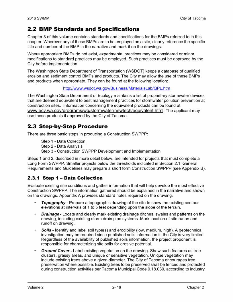
2.2 BMP Standards and SpecificationsChapter 3 of this volume contains standards and specifications for the BMPs referred to in this chapter. Wherever any of these BMPs are to be employed on a site, clearly reference the specific title and number of the BMP in the narrative and mark it on the drawings.
Where appropriate BMPs do not exist, experimental practices may be considered or minor modifications to standard practices may be employed. Such practices must be approved by the City before implementation.
The Washington State Department of Transportation (WSDOT) keeps a database of qualified erosion and sediment control BMPs and products. The City may allow the use of these BMPs and products when appropriate. They can be found at the following location:
http://www.wsdot.wa.gov/Business/MaterialsLab/QPL.htm
The Washington State Department of Ecology maintains a list of proprietary stormwater devices that are deemed equivalent to best management practices for stormwater pollution prevention at construction sites. Information concerning the equivalent products can be found at www.ecy.wa.gov/programs/wq/stormwater/newtech/equivalent.html. The applicant may use these products if approved by the City of Tacoma.
2.3 Step-by-Step ProcedureThere are three basic steps in producing a Construction SWPPP:
Step 1 - Data CollectionStep 2 - Data AnalysisStep 3 - Construction SWPPP Development and Implementation
Steps 1 and 2, described in more detail below, are intended for projects that must complete a Long Form SWPPP. Smaller projects below the thresholds indicated in Section 2.1 General Requirements and Guidelines may prepare a short form Construction SWPPP (see Appendix B).
2.3.1 Step 1 – Data CollectionEvaluate existing site conditions and gather information that will help develop the most effective Construction SWPPP. The information gathered should be explained in the narrative and shown on the drawings. Appendix A provides standard notes required on the drawing.
• Topography - Prepare a topographic drawing of the site to show the existing contour elevations at intervals of 1 to 5 feet depending upon the slope of the terrain.
• Drainage - Locate and clearly mark existing drainage ditches, swales and patterns on the drawing, including existing storm drain pipe systems. Mark location of site runon and runoff on drawing.
• Soils - Identify and label soil type(s) and erodibility (low, medium, high). A geotechnical investigation may be required since published soils information in the City is very limited. Regardless of the availability of published soils information, the project proponent is responsible for characterizing site soils for erosive potential.
• Ground Cover - Label existing vegetation on the drawing. Show such features as tree clusters, grassy areas, and unique or sensitive vegetation. Unique vegetation may include existing trees above a given diameter. The City of Tacoma encourages tree preservation where possible. Existing trees to be preserved shall be fenced and protected during construction activities per Tacoma Municipal Code 9.18.030, according to industry

City of Tacoma 2016 SWMM
Chapter 2 2- 17 Volume 2
standards (ANSI A300 Part 5) and the International Society of Arboriculture’s Best Management Practices – Managing Trees During Construction. In addition, indicate existing denuded or exposed soil areas.
• Critical Areas - Delineate critical areas adjacent to or within the site on the drawing. Such features as steep slopes, streams, floodplains, lakes, wetlands, sole source aquifers, and geologic hazard areas, etc., should be shown. Critical areas identified by the City of Tacoma are available on the City's GovME website. Delineate setbacks and buffer limits for these features on the drawings. Other related jurisdictional boundaries such as Shorelines Management and the Federal Emergency Management Agency (FEMA) base floodplain should also be shown on the drawings. Tacoma Municipal Code 13.10 and 13.11 contain setback requirements for critical areas and shorelines.
• Adjacent Areas - Identify existing buildings, roads, and facilities adjacent to or within the project site on the drawings. Identify existing and proposed utility locations, construction clearing limits, and erosion and sediment control BMPs on the drawings.
• Existing Encumbrances - Identify wells, existing and abandoned septic drain fields, utilities, easements, and site constraints.
• Precipitation Records - Volume 3, Appendix A contains Tacoma’s Design Storm Events. These can be used to help determine typical rainfall events for considering which BMPs are appropriate for your site.
2.3.2 Step 2 – Data AnalysisConsider the data collected in Step 1 to identify potential problems and limitations of the site. Determine those areas that have critical erosion hazards. The following are some important factors to consider in data analysis:
• Topography - The primary topographic considerations are slope steepness and slope length. The longer and steeper the slope, the greater the erosion potential. Erosion potential should be determined by a qualified engineer, soil professional, or certified erosion control specialist. Measures to decrease erosion potential shall be considered.
• Drainage - Natural drainage patterns that consist of overland flow, swales, and depressions should be used to convey runoff through the site to avoid construction of an artificial drainage system. Man-made ditches and waterways will become part of the erosion problem if they are not properly stabilized. Care should be taken to ensure that increased runoff from the site will not erode or flood the existing natural drainage system. Possible sites for temporary surface water retention and detention should be considered at this point.
Direct construction site runoff away from saturated soil areas where groundwater may be encountered and critical areas where drainage will concentrate. Preserve natural drainage patterns on the site.
• Soils - Evaluate soil properties such as surface and subsurface runoff characteristics, depth to impermeable layer, depth to seasonal groundwater table, permeability, shrink-swell potential, texture, settleability, and erodibility. Infiltration sites should be properly protected from clay and silt which will reduce infiltration capacities. Include any recommendations from geotechnical reports for handling construction stormwater runoff.
• Ground Cover - Ground cover is the most important factor in terms of preventing erosion. Existing vegetation that can be saved will prevent erosion better than constructed BMPs. Trees and other vegetation protect the soil structure. Disturb as little of the site as required to construct proposed improvements. If the existing vegetation cannot be saved, consider such practices as phasing of construction, temporary seeding,

2016 SWMM City of Tacoma
Volume 2 2- 18 Chapter 2
and mulching. Phasing of construction involves stabilizing one part of the site before disturbing another. In this way, the entire site is not disturbed at once.
• Critical Areas - Critical areas may include flood hazard areas, mine hazard areas, slide hazard areas, sole source aquifers, wetlands, stream banks, fish-bearing streams, and other water bodies. Any critical areas within or adjacent to the development shall be a key consideration on land development decisions. Critical areas and their buffers delineated on the drawings shall be clearly flagged in the field. Critical areas identified by the City of Tacoma are available on the City’s GovME website. Orange plastic fencing may be more useful than flagging to assure that equipment operators stay out of critical areas. Only unavoidable work should take place within critical areas and their buffers. Such unavoidable work will require special BMPs, permit restrictions, and mitigation plans. Additional requirements may be required by the Critical Areas Preservation Ordinance TMC 13.11 or the South Tacoma Groundwater Protection Ordinance, TMC 13.09.
• Adjacent Areas - An analysis of adjacent properties should focus on areas upslope and down slope from the construction project. Water bodies that will receive direct runoff from the site are a major concern. Investigate and identify runon to the site. The types, values, and sensitivities of and risks to downstream resources, such as private property, stormwater facilities, public infrastructure, or aquatic systems, should be evaluated. Develop a plan to route runon around areas disturbed by construction. Erosion and sediment controls should be selected accordingly.
• Precipitation Records - Volume 3, Appendix A contains Tacoma’s Design Storm Events. These can be used to help determine typical rainfall events for considering which BMPs are appropriate for your site.
• Timing of the Project - An important consideration in selecting BMPs is the timing and duration of the project. Projects that will proceed during the wet season and projects that will last through several seasons must take all necessary precautions to remain in compliance with the SWMM.
2.3.3 Step 3 – Construction SWPPP Development and AnalysisThe Construction SWPPP consists of two parts: a narrative and the drawings. This section describes the contents of the narrative and the drawings. This section is formatted as a checklist to aid the applicant and reviewer in development and review of the plan. Applicants are encouraged to complete and submit this form with their application. The Construction SWPPP shall be prepared as a stand-alone document.
The Department of Ecology has prepared a SWPPP template that offers a quick and convenient means for developing a SWPPP for development and redevelopment projects in the City of Tacoma. This template can be found on Ecology’s website at:
http://www.ecy.wa.gov/programs/wq/stormwater/construction/
NOTE: Ensure that BMP numbers and references match the City SWMM when using the Ecology template. Remove any sections or language that do not pertain to the project site.
The following checklist provides a tool to the applicant to determine if all the major items are included in the Construction SWPPP. The checklist will be used by reviewers to determine that SWPPPs meet all requirements and are complete. Applicants are encouraged to complete and submit this form with their application.
City of Tacoma 2016 SWMM
Chapter 2 2- 19 Volume 2
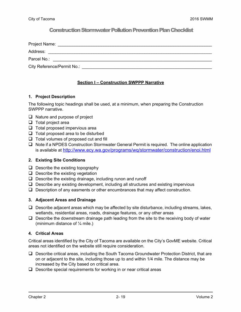
Construction Stormwater Pollution Prevention Plan Checklist
Project Name: ________________________________________________________________
Address: ____________________________________________________________________
Parcel No.: __________________________________________________________________
City Reference/Permit No.: ______________________________________________________
Section I – Construction SWPPP Narrative
1. Project Description
The following topic headings shall be used, at a minimum, when preparing the Construction SWPPP narrative.
Nature and purpose of project Total project area Total proposed impervious area Total proposed area to be disturbed Total volumes of proposed cut and fill Note if a NPDES Construction Stormwater General Permit is required. The online application
is available at http://www.ecy.wa.gov/programs/wq/stormwater/construction/enoi.html
2. Existing Site Conditions
Describe the existing topography Describe the existing vegetation Describe the existing drainage, including runon and runoff Describe any existing development, including all structures and existing impervious Description of any easments or other encumbrances that may affect construction.
3. Adjacent Areas and Drainage
Describe adjacent areas which may be affected by site disturbance, including streams, lakes, wetlands, residential areas, roads, drainage features, or any other areas
Describe the downstream drainage path leading from the site to the receiving body of water (minimum distance of ¼ mile.)
4. Critical Areas
Critical areas identified by the City of Tacoma are available on the City’s GovME website. Critical areas not identified on the website still require consideration.
Describe critical areas, including the South Tacoma Groundwater Protection District, that are on or adjacent to the site, including those up to and within 1/4 mile. The distance may be increased by the City based on critical area.
Describe special requirements for working in or near critical areas

2016 SWMM City of Tacoma
Volume 2 2- 20 Chapter 2
Construction Stormwater Pollution Prevention Plan Checklist
5. Soils
Describe on-site soils, include all relevent tests conducted. Soil name(s) Soil mapping unit Groundwater elevation and seasonal high groundwater elevation
The following information may be required at the direction of Environmental Services:
• Erodibility • Settleability • Permeability • Depth • Texture • Soil structure
6. Potential Erosion Problem Areas
Describe potential erosion problems on site
7. Construction Stormwater Pollution Prevention Elements
Describe how each of the Construction Stormwater Pollution Prevention Elements has been addressed.
Identify the type and location of BMPs used to satisfy the required element. Written justification identifying the reason an element is not applicable to the proposal.
13 Required Elements - Construction Stormwater Pollution Prevention Plan:
1. Preserve Vegetation and Mark Clearing Limits 2. Establish Construction Access 3. Control Flow Rates 4. Install Sediment Controls 5. Stabilize Soils 6. Protect Slopes 7. Protect Drain Inlets 8. Stabilize Channels and Outlets 9. Control Pollutants 10. Control Dewatering 11. Maintain BMPs 12. Manage the Project 13. Protect BMPs
8. Construction Phasing
Construction sequence Construction phasing (if proposed)

City of Tacoma 2016 SWMM
Chapter 2 2- 21 Volume 2
Construction Stormwater Pollution Prevention Plan Checklist
9. Construction Schedule
Provide a proposed construction schedule.
10. Financial/Ownership Responsibilities
Identify the person responsible for ensuring proper erosion and sediment control. Identify the property owner responsible for the initiation of bonds and/or other financial
securities. Describe bonds and/or other evidence of financial responsibility for liability associated
with erosion and sedimentation impacts. Maintenance bond
11. Engineering Calculations
Provide Design Calculations. BMPs such as sediment ponds and traps, interceptor swales, and stormwater detention require engineering calculations. Provide electronic modeling files.
Provide all assumptions and variables used in the design. Provide a signature and stamp from a Professional Engineer licensed in Washington State
for all engineering calculations.

2016 SWMM City of Tacoma
Volume 2 2- 22 Chapter 2
Construction Stormwater Pollution Prevention Plan ChecklistSection II - Erosion and Sediment Control Drawings
At a minimum, provide the following information and drawings as part of the Construction SWPPP erosion and sediment control plans. Include notes addressing construction phasing and scheduling on the drawings.
1. General
Provide a site map(s) showing the following features. The site map requirements may be met using multiple plan sheets for ease of legibility.
Vicinity map with roads and waters of the state within one mile of the site Address, Parcel Number, and street names labels Erosion and Sediment Control Notes A legal description of the property boundaries or an illustration of property lines (including
distances) in the drawings Project limits, including limits of construction and areas to remain undisturbed North arrow Existing structures and roads, if present Boundaries of soil types with labels Areas of potential erosion problems Points where surface water runs on and off the site Any onsite and adjacent surface waters, critical areas, their buffers, FEMA base flood
boundaries, and Shoreline Management boundaries Existing contours, drainage pipes and ditches/swales, and drainage basins, and the direction
of flow for the different drainage areas Final, and interim as appropriate, contours, drainage basins, and the direction of stormwater
flow during and upon completion of construction Areas of soil disturbance, including all areas affected by clearing, grading, and excavation Locations where stormwater discharges to surface waters or the City system during and upon
completion of construction Existing unique or valuable vegetation and the vegetation that is to be preserved Cut and fill slopes indicating top and bottom of slope catch lines Stockpile, waste storage, and vehicle storage/maintenance areas Total cut and fill quantities and the method of disposal for excess material All existing and proposed utilities and any associated easements Proposed structures including roads and parking areas Proposed infiltration facilities that may need protection Identify a responsible, certified erosion and sediment control lead (CESCL) as required
Include the CESCL’s telephone number and email address on drawings

City of Tacoma 2016 SWMM
Chapter 2 2- 23 Volume 2
Construction Stormwater Pollution Prevention Plan Checklist
2. Temporary Conveyance Systems
Show on the site map(s) the following temporary and permanent onsite and offsite conveyance features:
Locations for swales, interceptor trenches, or ditches Drainage pipes, ditches, or cut-off trenches associated with erosion and sediment control and
stormwater management Temporary and permanent pipe inverts and minimum slopes and cover Grades, dimensions, and direction of flow in all ditches and swales, culverts, and pipes Details for bypassing offsite runoff or runon around disturbed areas Locations and outlets of any dewatering systems
3. Location of Detention BMPs
Identify the location of detention BMPs used for construction stormwater runoff.
4. Temporary Erosion and Sediment Control Facilities
Show on the site map all major structural and nonstructural TESC BMPs, including but not limited to:
The location of sediment pond(s), pipes and structures Dimension pond berm widths and inside and outside pond slopes The trap/pond storage required and the depth, length, and width dimensions Typical section views through pond and outlet structure Typical details of gravel cone and standpipe, and/or other filtering devices Stabilization technique details for inlets and outlets Control/restrictor device location and details Stabilization practices, including details, for berms, slopes, and disturbed areas Rock specifications and detail for rock check dam, if used Spacing for rock check dams as required Front and side sections of typical rock check dams The location, detail, and specification for silt fence The construction entrance location and a detail
5. Detailed Drawings
Explain and illustrate with detailed drawings any best management practices used that are not referenced in the SWMM.

2016 SWMM City of Tacoma
Volume 2 2- 24 Chapter 2
Construction Stormwater Pollution Prevention Plan Checklist
6. Other Pollutant BMPs
Indicate on the site plan the location of BMPs to be used for the control of pollutants other than sediment.
7. Monitoring Locations
Indicate on the site map the water quality sampling locations, if required by the City or the Department of Ecology. Sampling stations shall be located in accordance with applicable permit requirements.
Describe inspection reporting responsibility, documentation, and filing.

City of Tacoma 2016 SWMM
Chapter 3 2- 25 Volume 2
Chapter 3 Standards and Specifications for Best Management Practices (BMPs)
Best Management Practices (BMPs) are defined as schedules of activities, prohibitions of practices, maintenance procedures, and structural and/or managerial practices, that when used singly or in combination, prevent or reduce the release of pollutants to waters of Washington State. This chapter contains standards and specifications for temporary BMPs to be used as applicable during the construction phase of a project.
Section 3.1 contains the standards and specifications for Source Control BMPs specific to construction operations. Source Control BMPs prevent contamination from entering stormwater runoff by controlling them at the source.
Section 3.2 contains the standards and specifications for Runoff Conveyance and Treatment BMPs. Runoff Conveyance and Treatment BMPs are structural devices or facilities intended to prevent pollutants from entering the downstream system.
The standards for each individual BMP are divided into four sections:
1. Purpose
2. Conditions of Use
3. Design and Installation Specifications
4. Maintenance Standards
Note that the “Conditions of Use” always refers to site conditions. As site conditions change, BMPs must be changed to remain in compliance with Minimum Requirement #2.
Information on stream bank stabilization is available in the Integrated Streambank Protection Guidelines, Washington State Department of Fish and Wildlife, 2003.

2016 SWMM City of Tacoma
Volume 2 2- 26 Chapter 3
3.1 Source Control BMPsTable 2 - 1, below shows the relationship of some of the BMPs in Section 3.1 to the 13 Elements of a SWPPP. Elements not shown are not satisfied through source control BMPs.
Table 2 - 1: Source Control BMPs by SWPPP Element
BMP or Element
Name
Element #1
Preserve Vegetation
/Mark Clearing Limits
Element #2 Establish
Construction Access
Element #5
Stabilize Soils
Element #6
Protect Slopes
Element #8
Stabilize Channel
and Outlets
Element #9
Control Pollution
Element #11
Maintain BMP
Element #12
Manage the
Project
Element #13
Protect BMPs
BMP C101 Perserving Natural Vegetation
X
BMP C102 Buffer Zones
X X
BMP C103 High Visibility Fencing
X X
BMP C105 Stabilize Construction Entrance/Exit
X
BMP C106 Wheel Wash
X
BMP C107 Construction Road/Parking Area Stabilization
X
BMP C120 Temporary and Permenant Seeding
X X
BMP C121 Mulching
X X
BMP C122 Nets and Blankets
X X X
BMP C123 Plastic Covering
X
BMP C125 Compost
X
BMP C126 Topsoiling
X
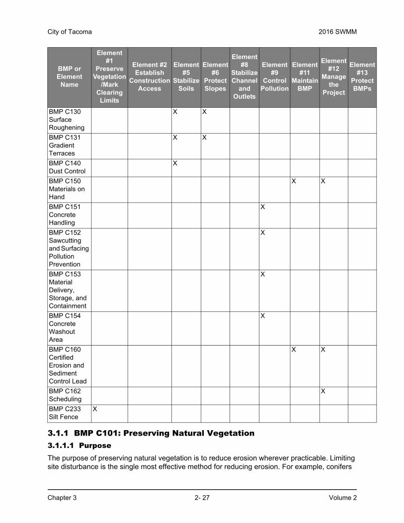
City of Tacoma 2016 SWMM
Chapter 3 2- 27 Volume 2
3.1.1 BMP C101: Preserving Natural Vegetation3.1.1.1 PurposeThe purpose of preserving natural vegetation is to reduce erosion wherever practicable. Limiting site disturbance is the single most effective method for reducing erosion. For example, conifers
BMP C130 Surface Roughening
X X
BMP C131 Gradient Terraces
X X
BMP C140 Dust Control
X
BMP C150 Materials on Hand
X X
BMP C151 Concrete Handling
X
BMP C152 Sawcutting and Surfacing Pollution Prevention
X
BMP C153 Material Delivery, Storage, and Containment
X
BMP C154 Concrete Washout Area
X
BMP C160 Certified Erosion and Sediment Control Lead
X X
BMP C162 Scheduling
X
BMP C233 Silt Fence
X
BMP or Element
Name
Element #1
Preserve Vegetation
/Mark Clearing Limits
Element #2 Establish
Construction Access
Element #5
Stabilize Soils
Element #6
Protect Slopes
Element #8
Stabilize Channel
and Outlets
Element #9
Control Pollution
Element #11
Maintain BMP
Element #12
Manage the
Project
Element #13
Protect BMPs

2016 SWMM City of Tacoma
Volume 2 2- 28 Chapter 3
can hold up to about 50 percent of all rain that falls during a storm. Up to 20-30 percent of this rain may never reach the ground but is taken up by the tree or evaporates. Another benefit is that the rain held in the tree can be released slowly to the ground after the storm.
3.1.1.2 Conditions of UseNatural vegetation should be preserved on steep slopes, near perennial and intermittent watercourses or swales, in wooded areas, and any other location practicable.
Phase construction to preserve natural vegetation on the project site for as long as possible during construction.
3.1.1.3 Design and Installation SpecificationsNatural vegetation can be preserved in natural clumps or as individual trees, shrubs and vines.
The preservation of individual plants is more difficult because heavy equipment is generally used to remove unwanted vegetation. The points to remember when attempting to save individual plants are:
• Is the plant worth saving? Consider the location, species, size, age, vigor, and the work involved. The City of Tacoma encourages the preservation of native vegetation and trees, where practicable.
• Existing trees to be preserved shall be fenced and protected during construction activities per Tacoma Municipal Code 9.18.030, according to industry standards (ANSI A300 Part 5) and the International Society of Arboriculture’s Best Management Practices – Managing Trees During Construction.
Trees and vegetation should be protected during construction per Tacoma Municipal Code 9.18.030, according to industry standards (ANSI A300 Part 5) and the International Society of Arboriculture’s Best Management Practices – Managing Trees from Construction. Described below are the most common types of injury that occur to trees. The language is adapted from the International Society of Arboriculture’s Best Management Practices – Managing Trees from Construction.
• Root cutting or damage which can be caused by excavation equipment, trenching equipment, burial of debris, fill over roots, and alterations made to the water table by grade changes.
• Soil compaction resulting from vehicle, equipment and foot traffic. Compacted soils permit less root growth and biological activity as a result of aeration, higher mechanical resistance to root penetration and slowed water movement.
• Mechanical injury to the tree. Trunks, roots, and tree crowns can be damaged by construction equipment. Injury can affect the ability of the tree or plant to transport water and nutrients, and removes the ability for the plant to protect against pathogens.
• Fill placed near the root collar can facilitate infection and encourage stem-girdling which will affect the long-term longevity of the tree or plant
3.1.1.4 Maintenance Standards• Inspect flagged and/or fenced areas regularly to make sure flagging or fencing has not
been removed or damaged. If the flagging or fencing has been damaged or visibility reduced, it shall be repaired or replaced immediately and visibility restored.
• If tree roots have been exposed or injured, prune cleanly with an appropriate pruning saw or loppers directly above the damaged roots and recover with native soils.

City of Tacoma 2016 SWMM
Chapter 3 2- 29 Volume 2
3.1.2 BMP C102: Buffer Zone3.1.2.1 PurposeAn undisturbed area or strip of natural vegetation or an established suitable planting that will provide a living filter to reduce soil erosion and runoff velocities.
3.1.2.2 Conditions of UseNatural buffer zones are used along streams, wetlands and other bodies of water that need protection from erosion and sedimentation. Vegetative buffer zones can be used to protect natural swales and can be incorporated into the natural landscaping of an area.
Critical-areas buffer zones should not be used as sediment treatment areas. Do not disturb critical area buffers. The City may expand the buffer widths temporarily to allow the use of the expanded area for removal of sediment.
3.1.2.3 Design and Installation Specifications• Preserve natural vegetation or plantings in clumps, blocks, or strips as this is generally
the easiest and most successful method. However, single specimen trees and plants should also be preserved.
• Leave all unstable slopes in their natural, undisturbed state.
• Mark clearing limits and keep all equipment and construction debris out of the natural areas. Steel construction fencing is the most effective method of protecting sensitive areas and buffers. Alternatively, wire-backed silt fence on steel posts is marginally effective. Flagging alone is typically not effective and will not be allowed.
• Keep all excavations and material storage areas outside the dripline of trees and shrubs.
• Do not push debris or extra soil into the buffer zone area because it will cause damage from burying and smothering.
• Vegetative buffer zones for streams, lakes or other waterways shall be established by the City or other state or federal permits or approvals.
3.1.2.4 Maintenance Standards• Inspect the area frequently to make sure flagging and fencing remains in place and the
area remains undisturbed.
3.1.3 BMP C103: High Visibility Fence3.1.3.1 PurposeFencing is intended to:
• Restrict clearing to approved limits.
• Prevent disturbance of sensitive areas, their buffers, and other areas required to be left undisturbed.
• Limit construction traffic to designated construction entrances or roads.
• Protect areas where marking with survey tape or flagging may not provide adequate protection.
3.1.3.2 Conditions of UseTo establish clearing limits, plastic or metal fence may be used:

2016 SWMM City of Tacoma
Volume 2 2- 30 Chapter 3
• At the boundary of sensitive areas, their buffers, and other areas required to be left uncleared.
• As necessary to control vehicle access to and on the site.
3.1.3.3 Design and Installation Specifications• High visibility plastic fence shall be composed of a high-density polyethylene material and
shall be at least four feet in height. Posts for the fencing shall be steel or wood and placed every 6 feet on center (maximum) or as needed to ensure rigidity. The fencing shall be fastened to the post every six inches with a polyethylene tie. On long continuous lengths of fencing, a tension wire or rope shall be used as a top stringer to prevent sagging between posts. The fence color shall be high visibility orange. The fence tensile strength shall be 360 lbs./ft. using the ASTM D4595 testing method.
• If appropriate, install fabric silt fence in accordance with BMP C233 to act as high visibility fence. Silt fence shall be at least 3 feet high and must be highly visible to meet the requirement of this BMP.
• Design and install metal fences according to the manufacturer's specifications.
• Metal fences shall be at least 3 feet high and must be highly visible.
• Do not wire or staple fences to trees.
3.1.3.4 Maintenance Standards• If the fence has been damaged or its visibility reduced, it shall be repaired or replaced
immediately and visibility restored.
3.1.4 BMP C105: Stabilized Construction Entrance/Exit3.1.4.1 PurposeConstruction entrances are stabilized to reduce the amount of sediment transported onto paved roads by vehicles or equipment by constructing a stabilized pad of quarry spalls at entrances and exits to construction sites.
3.1.4.2 Conditions of UseConstruction entrances shall be stabilized wherever traffic will be leaving a construction site and traveling on paved roads or other paved areas within 1,000 feet of the site.
Construction vehicle ingress and egress shall be limited to one route. Additional routes may be allowed for very large projects or linear projects.
For residential construction provide stabilized construction entrances/exits for each residence. Stabilized surfaces shall be of sufficient length/width to provide vehicle access/parking based upon lot size and configuration. See Figure 2 - 2.
3.1.4.3 Design and Installation Specifications• See Figure 2 - 1 and Figure 2 - 2 for details. Reduce the length of the entrance to the
maximum practicable size when the size or configuration of the site does not allow the full 100-foot length. Consult with the Erosion and Sediment Control Lead (ESCL) to determine if reducing the length of the entrance is acceptable.
• Construct stabilized construction entrance with a 12-inch thick pad of 4-inch to 8-inch quarry spalls, a 4-inch course of asphalt treated base (ATB), or using existing pavement. Protect permeable pavement surfaces per Element #13 as applicable. Do not use crushed concrete, cement, or calcium chloride for construction entrances stabilization.

City of Tacoma 2016 SWMM
Chapter 3 2- 31 Volume 2
• Place a separation geotextile under the spalls to prevent fine sediment from pumping up into the rock pad. The geotextile shall meet the following standards:
◦ Grab Tensile Strength (ASTM D4751) – 200 psi min.
◦ Grab Tensile Elongation (ASTM D4632) – 30% max.
◦ Mullen Burst Strength (ASTM D3786-80a) – 400 psi min.
◦ AOS (ASTM D4751) – 20 to 45 (U.S. standard sieve size)
• Consider early installation of the first lift of asphalt or extra concrete in areas that will be paved; this can be used as a stabilized entrance.
• Install fencing (see BMPs C103) as necessary to restrict traffic to the construction entrance.
• Whenever possible, construct the entrance on a firm, compacted subgrade. This can substantially increase the effectiveness of the pad and reduce the need for maintenance
• If possible, install the stabilized construction entrance on the uphill side of the site so that stormwater will not pond near the stabilized construction entrance.
• Construction entrance should avoid crossing existing sidewalks if possible. If a construction entrance must cross a sidewalk, the sidewalk must be covered and protected from sediment leaving the site.
3.1.4.4 Maintenance Standards• Add quarry spalls if the pad is no longer in accordance with the specifications.
• If the entrance is not preventing sediment from being tracked onto pavement, then alternative measures to keep the streets free of sediment shall be used. This may include street sweeping, an increase in the dimensions of the entrance, or the installation of a wheel wash.
• No tracking of sediment onto the roadway is allowed. If sediment is tracked onto the road, immediately clean the road thoroughly by shoveling or pickup sweeping. Transport sediment to a controlled sediment disposal area.
• Perform street sweeping by hand or with a high efficiency sweeper. Do not use a non-high efficiency mechanical sweeper because this creates dust and throws soils into storm systems or conveyance ditches.
• Keep streets clean at ALL times. Clean tracked sediment immediately.
• Street washing of sediment to the storm drain system is not allowed.
• If sediment is discharged to the stormwater system it is the responsibility of the applicant to clean the downstream system.
• Immediately remove any quarry spalls that are loosened from the pad and end up on the roadway.
• Install fencing if vehicles are entering or exiting the site at points other than the construction entrance(s).
• Upon project completion and site stabilization, permanently stabilize all construction accesses intended as permanent access for maintenance.

2016 SWMM City of Tacoma
Volume 2 2- 32 Chapter 3
Figure 2 - 1. Stabilized Construction Entrance
Figure 2 - 2 shows a small site, stabilized construction entrance.
100' MIN.

City of Tacoma 2016 SWMM
Chapter 3 2- 33 Volume 2
Figure 2 - 2. Small-Site Stabilized Construction Entrance

2016 SWMM City of Tacoma
Volume 2 2- 34 Chapter 3
3.1.5 BMP C106: Wheel Wash3.1.5.1 PurposeWheel washes reduce the amount of sediment transported onto paved roads by motor vehicles.
3.1.5.2 Conditions of Use• Can be used when a stabilized construction entrance (see BMP C105) is not preventing
sediment from being tracked onto pavement.
• Wheel washing is generally an effective BMP when installed with careful attention to topography. For example, a wheel wash can be detrimental if installed at the top of a slope abutting a right-of-way where the water from the dripping truck can run unimpeded into the street.
• Pressure washing combined with an adequately sized and surfaced pad with direct drainage to a large 10-foot x 10-foot sump can be very effective.
• Discharge wheel wash or tire bath wastewater to a separate onsite treatment system that prevents discharge to surface water or to the wastewater system with a City of Tacoma Special Approved Discharge permit.
• Wheel wash or tire bath wastewater shall not include wastewater from concrete washout areas.
3.1.5.3 Design and Installation Specifications• Suggested details are shown in Figure 2 - 3. The City may allow other designs. A
minimum of 6 inches of asphalt treated base (ATB) over crushed base material or 8 inches over a good subgrade is recommended to pave the wheel wash.
• Use a low clearance truck to test the wheel wash before paving. Either a belly dump or lowboy will work well to test clearance.
• Keep the water level from 12 to 14 inches deep to avoid damage to truck hubs and filling the truck tongues with water.
• Midpoint spray nozzles are only needed in extremely muddy conditions.
• Design wheel wash systems with a small grade change, 6 to 12 inches for a 10-foot-wide pond, to allow sediment to flow to the low side of pond to help prevent re-suspension of sediment. A drainpipe with a 2- to 3-foot riser should be installed on the low side of the pond to allow for easy cleaning and refilling. Polymers may be used to promote coagulation and flocculation in a closed-loop system. Polyacrylamide (PAM) added to the wheel wash water at a rate of 0.25 - 0.5 pounds per 1,000 gallons of water increases effectiveness and reduces cleanup time. If PAM is already being used for dust or erosion control and is being applied by a water truck, the same truck can be used to change the wash water.
3.1.5.4 Maintenance Standards• The wheel wash should start out the day with fresh water.
• The wash water should be changed as necessary with a minimum of once per day. On large earthwork jobs where more than 10-20 trucks per hour are expected, the wash water will need to be changed more often.
• Wheel wash or tire bath wastewater shall be discharged to a separate onsite treatment system, such as closed-loop recirculation or land application, or to the sanitary sewer with a City of Tacoma Special Approved Discharge permit.


2016 SWMM City of Tacoma
Volume 2 2- 36 Chapter 3
3.1.6 BMP C107: Construction Road/Parking Area Stabilization3.1.6.1 PurposeStabilizing subdivision roads, parking areas and other onsite vehicle transportation routes immediately after grading reduces erosion caused by construction traffic or runoff.
3.1.6.2 Conditions of Use• Stabilize roads or parking areas wherever they are constructed, whether permanent or
temporary, for use by construction traffic.
• Install fencing (see BMPs C103), if necessary, to limit the access of vehicles to only those roads and parking areas that are stabilized.
3.1.6.3 Design and Installation Specifications• On areas that will receive asphalt as part of the project, install the first lift as soon as
possible.
• Use one of the following methods to stabilize the area immediately after grading or utility installation.
◦ Pave the road/parking area.
◦ Apply 6-inch depth of 2- to 4-inch crushed rock, gravel base, or crushed surfacing base course.
◦ Apply a 4-inch course of asphalt treated base (ATB).
◦ Apply cement of calcium chloride1.
◦ Apply a 6-inch depth of hog fuel (only if the area will not be used for permanent roads, parking areas or structures).
• Whenever possible, place construction roads and parking areas on a firm, compacted subgrade.
• Temporary road gradients shall not exceed 15 percent. Carefully grade roadways to drain. Provide drainage ditches on each side of the roadway in the case of a crowned section, or on one side in the case of a super-elevated section. Direct drainage ditches to a sediment control BMP.
• Rather than relying on ditches, it may also be possible to grade the road so that runoff sheet flows into a heavily vegetated area with a well-developed topsoil. Landscaped areas are not adequate. If this area has at least 50 feet of vegetation, then it is generally preferable to use the vegetation to treat runoff, rather than a sediment pond or trap. The 50 feet shall not include wetlands. If runoff is allowed to sheetflow through adjacent vegetated areas, it is vital to design the roadways and parking areas so that no concentrated runoff is created.
• Protect storm drain inlets to prevent sediment-laden water entering the storm drain system (see BMP C220).
1.If cement or cement kiln dust is used for roadbase stabilization, pH monitoring and BMPs are nec-essary to evaluate and minimize the effects on stormwater.

City of Tacoma 2016 SWMM
Chapter 3 2- 37 Volume 2
3.1.6.4 Maintenance Standards• Inspect stabilized areas regularly, especially after large storm events.
• Add crushed rock, gravel base, hog fuel, etc. as required to maintain a stable driving surface and to stabilize any eroded areas.
• Following construction, restore all areas to preconstruction condition or better to prevent future erosion.
• No tracking of sediment onto the roadway is allowed. If sediment is tracked onto road, clean the road thoroughly by shoveling or pickup sweeping.
3.1.7 BMP C120: Temporary and Permanent Seeding3.1.7.1 PurposeSeeding reduces erosion by stabilizing exposed soils. A well-established vegetative cover is one of the most effective methods of reducing erosion.
3.1.7.2 Conditions of Use• Seeding may be used throughout the project on disturbed areas that have reached final
grade or that will remain unworked.
• Channels that will be vegetated should be installed before major earthwork and hydroseeded with a Bonded Fiber Matrix. The vegetation should be well established (i.e., 75 percent cover) before water is allowed to flow in the ditch. With channels that will have high flows, install erosion control blankets over the hydroseed. If vegetation cannot be established from seed before water is allowed in the ditch, sod should be installed in the bottom of the ditch over hydromulch and blankets.
• Seed detention ponds as required.
• Mulch is required at all times because it protects seeds from heat, moisture loss, and transport due to runoff.
Mulch can be applied on top of the seed or simultaneously by hydroseeding. See BMP C121: Mulching for specifications.
• All disturbed areas shall be reviewed in late August to early September and all seeding shall be completed by the end of September. Otherwise, vegetation will not establish itself enough to provide more than average protection.
• At final site stabilization, seed and mulch all disturbed areas not otherwise vegetated or stabilized. Final stabilization means the completion of all soil disturbing activities at the site and the establishment of a permanent vegetative cover, or equivalent permanent stabilization measures (such as pavement, riprap, gabions or geotextiles) which will prevent erosion.
3.1.7.3 Design and Installation Specifications• Seed during seasons most conducive to plant growth.
◦ The optimum seeding windows for western Washington are April 1 through June 30 and September 1 through October 1.
◦ Seeding that occurs between July 1 and August 30 will require irrigation until 75 percent grass cover is established.

2016 SWMM City of Tacoma
Volume 2 2- 38 Chapter 3
◦ Seeding that occurs between October 1 and March 30 will require a mulch or straw cover until 75 percent grass cover is established.
• Deviation from these specifications will be allowed if alternatives are developed by a licensed Landscape Professional and approved by the City.
• To prevent seed from being washed away, confirm that all required surface water control measures have been installed.
• The seedbed should be firm and rough. All soil should be roughened no matter what the slope. If compaction is required for engineering purposes, track walk slopes before seeding. Backblading or smoothing of slopes greater than 4:1 is not allowed if they are to be seeded.
• New and more effective restoration-based landscape practices rely on deeper incorporation than that provided by a simple single-pass rototilling treatment. Wherever practical, the subgrade should be initially ripped to improve long-term permeability, infiltration, and water inflow qualities. At a minimum for permanent areas, use soil amendments to achieve organic matter and permeability performance defined in engineered soil/landscape systems. For systems that are deeper than 8 inches, complete the rototilling process in multiple lifts, or prepare the soil system properly and then place it to achieve the specified depth.
• The use of fertilizers is discouraged. Fertilizers should only be used where necessary to ensure growth. Amending soils per BMPL613 should be considered (and may be required for permanent lawn and landscaped areas) as the first measure for ensuring vegetation growth. If fertilization is necessary, naturally-derived fertilizers should be chosen over chemically-derived fertilizers. Apply fertilizers per manufacturer’s direction. Always use slow-release fertilizers.
• Hydroseed applications shall include a minimum of 1,500 pounds per acre of mulch with 3 percent tackifier. See BMP C121: Mulching for specifications.
• On steep slopes, Bonded Fiber Matrix (BFM) or Mechanically Bonded Fiber Matrix (MBFM) products should be used. BFM/MBFM products are applied at a minimum rate of 3,000 pounds per acre of mulch with approximately 10 percent tackifier. Application is made so that a minimum of 95 percent soil coverage is achieved. Numerous products are available commercially and should be installed per manufacturer’s instructions. Most products require 24-36 hours to cure before a rainfall and cannot be installed on wet or saturated soils. Generally, these products come in 40-50 pound bags and include all necessary ingredients except for seed and fertilizer.
• BFMs and MBFMs have some advantages over blankets:
◦ No surface preparation required;
◦ Can be installed via helicopter in remote areas;
◦ On slopes steeper than 2.5:1, blanket installers may need to be roped and harnessed for safety;
• In most cases, the shear strength of blankets is not a factor when used on slopes, only when used in channels. BFMs and MBFMs are good alternatives to blankets in most situations where vegetation establishment is the goal.
• When installing seed via hydroseeding operations, only about 1/3 of the seed actually ends up in contact with the soil surface. This reduces the ability to establish a good stand of grass quickly. One way to overcome this is to increase seed quantities by up to 50 percent.

City of Tacoma 2016 SWMM
Chapter 3 2- 39 Volume 2
• Vegetation establishment can also be enhanced by dividing the hydromulch operation into two phases:
◦ Phase 1- Install all seed and fertilizer with 25-30 percent mulch and tackifier onto soil in the first lift;
◦ Phase 2- Install the rest of the mulch and tackifier over the first lift.
• An alternative is to install the mulch, seed, fertilizer, and tackifier in one lift. Then, spread or blow straw over the top of the hydromulch at a rate of about 800-1000 pounds per acre. Hold straw in place with a standard tackifier. Both of these approaches will increase cost moderately but will greatly improve and enhance vegetative establishment. The increased cost may be offset by the reduced need for:
◦ Irrigation
◦ Reapplication of mulch
◦ Repair of failed slope surfaces
◦ This technique works with standard hydromulch (1,500 pounds per acre minimum) and BFM/MBFMs (3,000 pounds per acre minimum).
• Provide a healthy topsoil to areas to be permanently landscaped. This will reduce the need for fertilizers, improve overall topsoil quality, provide for better vegetal health and vitality, improve hydrologic characteristics, and reduce the need for irrigation. See the Post-Construction Soil Quality and Depth BMP in Volume 6 for more information. Compost shall meet specification in Volume 5, Apendix E. City of Tacoma Tagro Potting Soil can be used as an alternative to the compost component. Areas that will be seeded only and not landscaped may need compost or meal-based mulch included in the hydroseed in order to establish vegetation. Replace native topsoil on the disturbed soil surface before application.
• Seed that is installed as a temporary measure may be installed by hand if it will be covered by straw, mulch, or topsoil. Seed that is installed as a permanent measure may be installed by hand on small areas (usually less than 1 acre) that will be covered with mulch, topsoil, or erosion blankets.
• The seed mixes listed below include recommended mixes for both temporary and permanent seeding. These mixes, with the exception of the wetland mix, shall be applied at a rate of 120 pounds per acre. This rate can be reduced if soil amendments or slow-release fertilizers are used. Local suppliers or the local conservation district should be consulted for their recommendations because the appropriate mix depends on a variety of factors, including location, exposure, soil type, slope, and expected foot traffic. Alternative seed mixes approved by the City of Tacoma may be used.
• Table 2 - 2 represents the standard mix for those areas where just a temporary vegetative cover is required.
• Table 2 - 3 provides one recommended possibility for landscaping seed.
• The turf seed mix in Table 2 - 4 is for dry situations. The advantage is that this mix requires very little maintenance.
• Table 2 - 5 presents a mix recommended for bioswales and other intermittently wet areas.
• The seed mix shown in Table 2 - 6 is a recommended low-growing, relatively non-invasive seed mix appropriate for very wet areas that are not regulated wetlands. Other mixes may be appropriate, depending on the soil type and hydrology of the area. Recent

2016 SWMM City of Tacoma
Volume 2 2- 40 Chapter 3
research suggests that bentgrass (agrostis sp.) should be emphasized in wet-area seed mixes. Apply this mixture at a rate of 60 pounds per acre.
• The meadow seed mix in Table 2 - 7 is recommended for areas that will be maintained infrequently or not at all and where colonization by native plants is desirable. Likely applications include rural road and utility right-of-way. Seeding should take place in September or very early October in order to obtain adequate establishment prior to the winter months. The appropriateness of clover in the mix may need to be considered, as this can be a fairly invasive species. If the soil is amended, the addition of clover may not be necessary.
3.1.7.4 Maintenance Standards• Reseed any seeded areas that fail to establish at least 80 percent cover within 6 weeks
from the initial seeding (100 percent cover for areas that receive sheet or concentrated flows). If reseeding is ineffective, use an alternate method, such as sodding, mulching, or nets/blankets. If winter weather prevents adequate grass growth, this time limit may be relaxed at the discretion of the City.
• After adequate cover is achieved, reseed and protect with mulch any areas that experience erosion. If the erosion problem is drainage related, the problem shall be fixed and the eroded area reseeded and protected by mulch.
• Water seeded areas if necessary. Watering shall not cause runoff.
Table 2 - 2: Temporary Erosion Control Seed Mix
% Weight % Purity % Germination
Chewings or annual bluegrassFestuca rubra var. commutate or Poa anna
40 98 90
Perrenial ryeLolium perenne
50 98 90
Redtop or colonial bentgrassAgrostis alba or Agrostis tenuis
5 92 85
White Dutch cloverTrifolium repens
5 98 90
Table 2 - 3: Landscaping Seed Mix
% Weight % Purity % Germination
Perennial ryeLolium perenne
70 98 90
Chewings and red fescue blendFestuca rubra var commutate or Festuca rubra
30 98 90
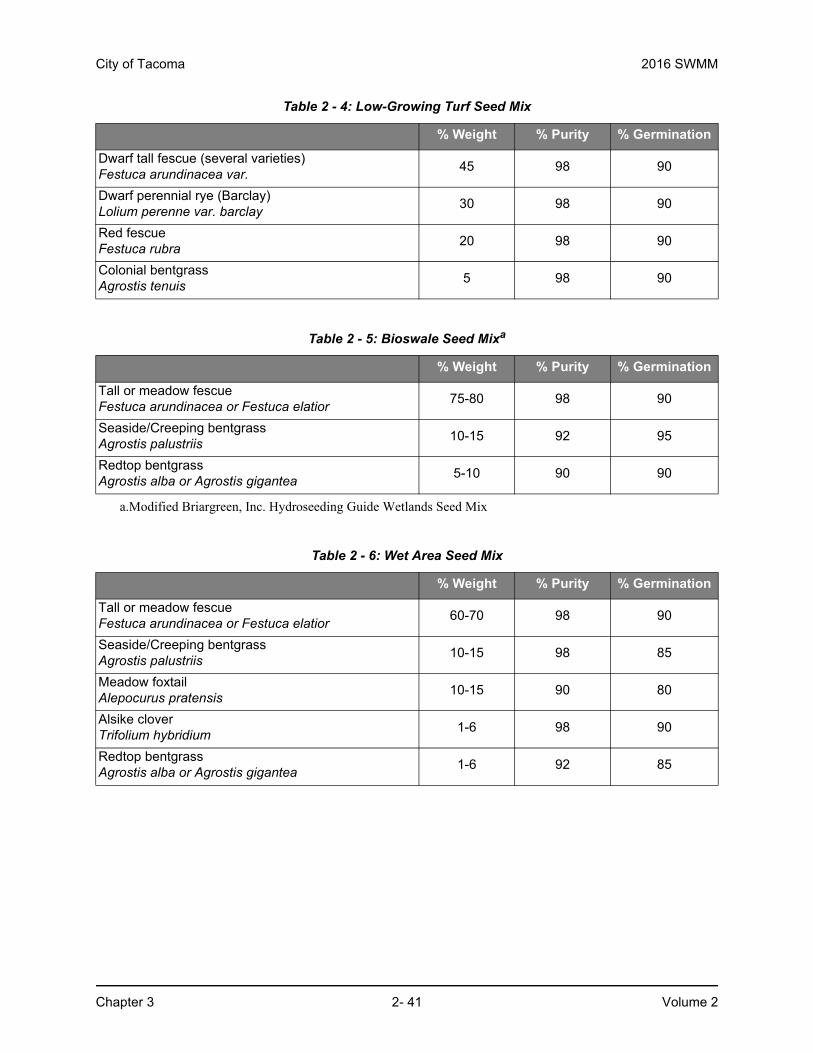
City of Tacoma 2016 SWMM
Chapter 3 2- 41 Volume 2
Table 2 - 4: Low-Growing Turf Seed Mix
% Weight % Purity % Germination
Dwarf tall fescue (several varieties)Festuca arundinacea var.
45 98 90
Dwarf perennial rye (Barclay)Lolium perenne var. barclay
30 98 90
Red fescueFestuca rubra
20 98 90
Colonial bentgrassAgrostis tenuis
5 98 90
Table 2 - 5: Bioswale Seed Mixa
a.Modified Briargreen, Inc. Hydroseeding Guide Wetlands Seed Mix
% Weight % Purity % Germination
Tall or meadow fescueFestuca arundinacea or Festuca elatior
75-80 98 90
Seaside/Creeping bentgrassAgrostis palustriis
10-15 92 95
Redtop bentgrassAgrostis alba or Agrostis gigantea
5-10 90 90
Table 2 - 6: Wet Area Seed Mix
% Weight % Purity % Germination
Tall or meadow fescueFestuca arundinacea or Festuca elatior
60-70 98 90
Seaside/Creeping bentgrassAgrostis palustriis
10-15 98 85
Meadow foxtailAlepocurus pratensis
10-15 90 80
Alsike cloverTrifolium hybridium
1-6 98 90
Redtop bentgrassAgrostis alba or Agrostis gigantea
1-6 92 85
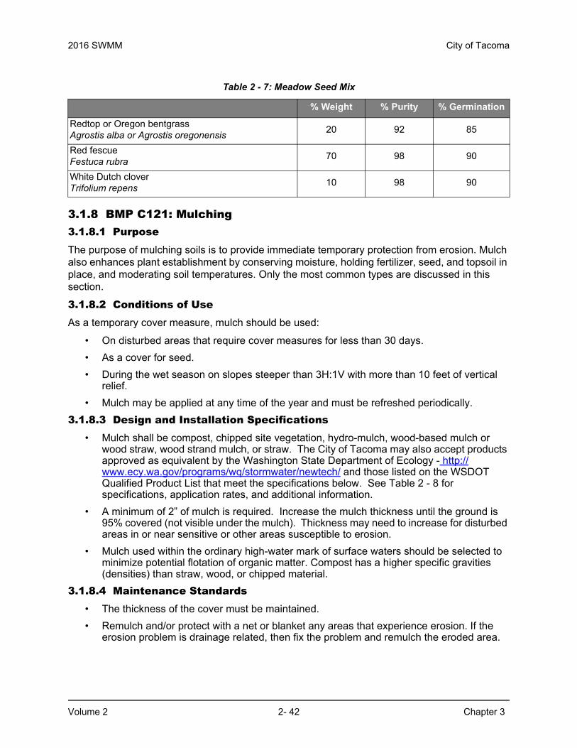
2016 SWMM City of Tacoma
Volume 2 2- 42 Chapter 3
3.1.8 BMP C121: Mulching 3.1.8.1 PurposeThe purpose of mulching soils is to provide immediate temporary protection from erosion. Mulch also enhances plant establishment by conserving moisture, holding fertilizer, seed, and topsoil in place, and moderating soil temperatures. Only the most common types are discussed in this section.
3.1.8.2 Conditions of UseAs a temporary cover measure, mulch should be used:
• On disturbed areas that require cover measures for less than 30 days.
• As a cover for seed.
• During the wet season on slopes steeper than 3H:1V with more than 10 feet of vertical relief.
• Mulch may be applied at any time of the year and must be refreshed periodically.
3.1.8.3 Design and Installation Specifications• Mulch shall be compost, chipped site vegetation, hydro-mulch, wood-based mulch or
wood straw, wood strand mulch, or straw. The City of Tacoma may also accept products approved as equivalent by the Washington State Department of Ecology - http://www.ecy.wa.gov/programs/wq/stormwater/newtech/ and those listed on the WSDOT Qualified Product List that meet the specifications below. See Table 2 - 8 for specifications, application rates, and additional information.
• A minimum of 2” of mulch is required. Increase the mulch thickness until the ground is 95% covered (not visible under the mulch). Thickness may need to increase for disturbed areas in or near sensitive or other areas susceptible to erosion.
• Mulch used within the ordinary high-water mark of surface waters should be selected to minimize potential flotation of organic matter. Compost has a higher specific gravities (densities) than straw, wood, or chipped material.
3.1.8.4 Maintenance Standards• The thickness of the cover must be maintained.
• Remulch and/or protect with a net or blanket any areas that experience erosion. If the erosion problem is drainage related, then fix the problem and remulch the eroded area.
Table 2 - 7: Meadow Seed Mix
% Weight % Purity % Germination
Redtop or Oregon bentgrassAgrostis alba or Agrostis oregonensis
20 92 85
Red fescueFestuca rubra
70 98 90
White Dutch cloverTrifolium repens
10 98 90

City of Tacoma 2016 SWMM
Chapter 3 2- 43 Volume 2
Table 2 - 8: Mulch Standards and Guidelines
Compost
• Compost shall:
◦ Meet the definition for “composted material” per WAC 173-350-100 and comply with standards in WAC 173-350-220, except the feedstock may contain biosolids or manure feedstocks.
◦ Be coarse compost meeting the following size gradations (by dry weight) when tested in accordance with the U.S. Composting Council “Test Methods for the Examination of Compost and Composting” (TMECC) Test Method 02.02-B.
◦ Have no visible water or dust during handling.
◦ Have soil organic matter content of 40% to 65%.
◦ Have a carbon to nitrogen ratio below 25:1. Carbon to nitrogen ratio may be as high as 35:1 for plantings composed entirely of plants native to the Puget Sound Lowlands region.
◦ Be applied a minimum of 2” thick (~100 tons/acre) though thicker application rates may provide more effective control.
• Do not use near wetlands or phosphorus impaired waterbodies.
• Compost can be later tilled into soils to help meet the requirements of BMP L613 – Post-Construction Soil Quality and Depth as required per Minimum Requirement #5.
Compost specifications are also contained in Vol 5, Appendix E.
Chipped Site Vegetation
• Chipped site vegetation shall:
◦ Have an average size of 2-4” with gradations from fine to 6” in length for texture, variation, and interlocking properties.
◦ Be applied a minimum of 2” thick.
• Do not apply on slopes greater than 10%.
• Do not use within 200 feet of surface waterbodies.
• Using chipped site vegetation is a cost-effective way to dispose of debris associated with clearing and grubbing material. The decomposition of the chipped vegetation may help impart nutrients for grass establishment.
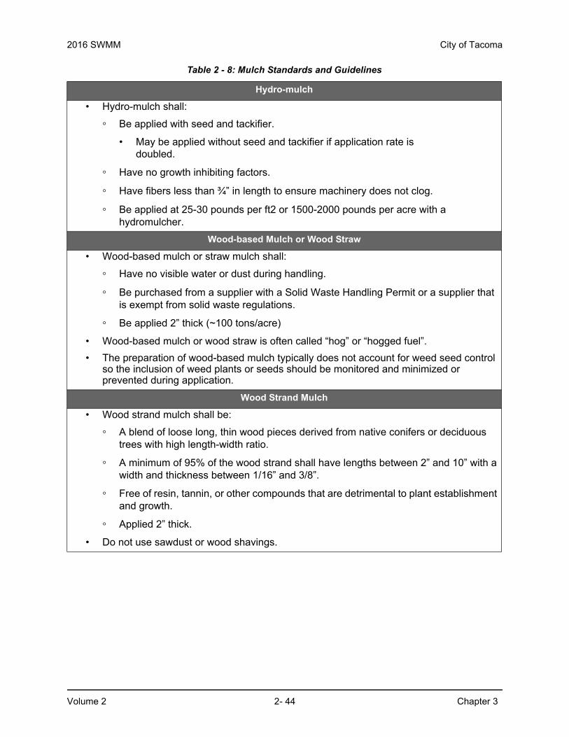
2016 SWMM City of Tacoma
Volume 2 2- 44 Chapter 3
Hydro-mulch
• Hydro-mulch shall:
◦ Be applied with seed and tackifier.
• May be applied without seed and tackifier if application rate is doubled.
◦ Have no growth inhibiting factors.
◦ Have fibers less than ¾” in length to ensure machinery does not clog.
◦ Be applied at 25-30 pounds per ft2 or 1500-2000 pounds per acre with a hydromulcher.
Wood-based Mulch or Wood Straw
• Wood-based mulch or straw mulch shall:
◦ Have no visible water or dust during handling.
◦ Be purchased from a supplier with a Solid Waste Handling Permit or a supplier that is exempt from solid waste regulations.
◦ Be applied 2” thick (~100 tons/acre)
• Wood-based mulch or wood straw is often called “hog” or “hogged fuel”.
• The preparation of wood-based mulch typically does not account for weed seed control so the inclusion of weed plants or seeds should be monitored and minimized or prevented during application.
Wood Strand Mulch
• Wood strand mulch shall be:
◦ A blend of loose long, thin wood pieces derived from native conifers or deciduous trees with high length-width ratio.
◦ A minimum of 95% of the wood strand shall have lengths between 2” and 10” with a width and thickness between 1/16” and 3/8”.
◦ Free of resin, tannin, or other compounds that are detrimental to plant establishment and growth.
◦ Applied 2” thick.
• Do not use sawdust or wood shavings.
Table 2 - 8: Mulch Standards and Guidelines

City of Tacoma 2016 SWMM
Chapter 3 2- 45 Volume 2
Straw
• Straw shall be:
◦ Air-dried.
◦ Free from undesirable seed and coarse material.
◦ Applied 2”-3” thick (5 bales per 1000 ft2 or 2-3 tons per acre)
• Thickness may be reduced by half when used with seeding.
• Hand-application requires a greater thickness than blown straw to ensure required coverage.
◦ Held in place by crimping, using a tackifier, or covering with netting. Blown straw shall be held in place using a tackifier.
• Although straw can be cost-effect, straw can introduce and/or encourage weed species and has no long-term benefits so should only be used when other materials are unavailable.
• Do not used within the ordinary high-water elevation of surface waters (due to flotation).
Table 2 - 8: Mulch Standards and Guidelines

2016 SWMM City of Tacoma
Volume 2 2- 46 Chapter 3
3.1.9 BMP C122: Nets and Blankets3.1.9.1 PurposeErosion control nets and blankets are intended to prevent erosion and hold seed and mulch in place on steep slopes and in channels so that vegetation can become well established. In addition, some nets and blankets can be used to permanently reinforce turf to protect drainage ways during high flows. Nets (commonly called matting) are strands of material woven into an open, but high-tensile strength net (for example, coconut fiber matting). Blankets are strands of material that are not tightly woven, but instead form a layer of interlocking fibers, typically held together by a biodegradable or photodegradable netting (for example, excelsior or straw blankets). They generally have lower tensile strength than nets, but cover the ground more completely. Coir (coconut fiber) fabric comes as both nets and blankets.
3.1.9.2 Conditions of UseErosion control nets and blankets should be used:
• To aid permanent vegetated stabilization of slopes 2H:1V or greater and with more than 10 feet of vertical relief.
• For drainage ditches and swales (highly recommended). The application of appropriate netting or blanket to drainage ditches and swales can protect bare soil from channelized runoff while vegetation is established. Nets and blankets also can capture a great deal of sediment due to their open, porous structure. Synthetic nets and blankets can be used to permanently stabilize channels and may provide a cost-effective, environmentally preferable alternative to riprap. 100 percent synthetic blankets manufactured for use in ditches may be easily reused as temporary ditch liners.
• Disadvantages of blankets include:
◦ Surface preparation required;
◦ On slopes steeper than 2.5:1, blanket installers may need to be roped and harnessed for safety;
• Advantages of blankets include:
◦ Can be installed without mobilizing special equipment;
◦ Can be installed by anyone with minimal training;
◦ Can be installed in stages or phases as the project progresses;
◦ Seed and fertilizer can be hand-placed by the installers as they progress down the slope;
◦ Can be installed in any weather;
◦ There are numerous types of blankets that can be designed with various parameters in mind. Those parameters include: fiber blend, mesh strength, longevity, biodegradability, cost, and availability.
3.1.9.3 Design and Installation Specifications • See Figure 2 - 4 and Figure 2 - 5 for typical orientation and installation of blankets used in
channels and as slope protection. Note: these are typical only; all blankets must be installed per manufacturer’s installation instructions.

City of Tacoma 2016 SWMM
Chapter 3 2- 47 Volume 2
• Installation is critical to the effectiveness of these products. If good ground contact is not achieved, runoff can concentrate under the product, resulting in significant erosion.
Installation of Blankets on Slopes:
• Complete final grade and track walk up and down the slope.
• Slope surface shall be free of rocks, clods, sticks and grass. Nets/blankets shall have good contact with the soil.
• Apply permanent seeding per BMP C120 or mulching per BMP C121 before placing net/blanket.
• Dig a small trench, approximately 12 inches wide by 6 inches deep along the top of the slope. Cover with soil to secure.
• Install the leading edge of the blanket into the small trench, backfill the trench with soil and staple approximately every 18 inches. Staples are metal. ”U”-shaped, and a minimum of 6 inches long. Longer staples are used in sandy soils. Biodegradable stakes are also available and should be used where applicable.
• Roll the blanket slowly down the slope as the installer walks backwards. The blanket rests against the installer’s legs. Staples are installed as the blanket is unrolled. It is critical that the proper staple pattern in used for the blanket being installed. The blanket should not be allowed to roll down the slope on its own as this stretches the blanket, making it impossible to maintain soil contact. In addition, no one should be allowed to walk on the blanket after it is in place.
• If the blanket is not long enough to cover the entire slope length, the trailing edge of the upper blanket should overlap the leading edge of the lower blanket and be stapled. On steeper slopes, this overlap should be installed in a small trench, covered with soil and stapled.
• With the variety of products available, it is impossible to cover all the details of appropriate use and installation. Therefore, it is critical that the design engineer consults the manufacturer's information and that a site visit takes place in order to ensure that the product specified is appropriate. Information is also available at the WSDOT website:
http://www.wsdot.wa.gov/environment/
• Jute matting must be used in conjunction with mulch (BMP C121). Excelsior, woven straw blankets, and coir (coconut fiber) blankets may be installed without mulch. There are many other types of erosion control nets and blankets on the market that may be appropriate in certain circumstances.
• In general, most nets (e.g., jute matting) require mulch in order to prevent erosion because they have a fairly open structure. Blankets typically do not require mulch because they usually provide complete protection of the surface.
• Extremely steep, unstable, wet, or rocky slopes are often appropriate candidates for use of synthetic blankets, as are riverbanks, beaches, and other high-energy environments. If synthetic blankets are used, the soil should be hydromulched first.
• 100 percent biodegradable blankets are available for use in sensitive areas. These organic blankets are usually held together with a paper or fiber mesh and stitching which may last up to a year.
• Most netting used with blankets is photodegradable, meaning it will break down under sunlight (not UV stabilized). However, this process can take months or years even under bright sun. Once vegetation is established, sunlight does not reach the mesh. It is not

2016 SWMM City of Tacoma
Volume 2 2- 48 Chapter 3
uncommon to find non-degraded netting still in place several years after installation. This can be a problem if maintenance requires the use of mowers or ditch cleaning equipment. In addition, birds and small animals can become trapped in the netting.
3.1.9.4 Maintenance Standards• Good contact with the ground must be maintained, and erosion must not occur beneath
the net or blanket.
• Repair or staple any areas of the net or blanket that are damaged or not in close contact with the ground.
• If erosion occurs due to poorly controlled drainage, fix the problem and protect the eroded area.

City of Tacoma 2016 SWMM
Chapter 3 2- 49 Volume 2
Figure 2 - 4. Nets and Blankets – Slope Installation
Min. 2“Overlap
Slope surface shall be smooth beforeplacement for proper soil contact.
Stapling pattern as permanufacturer’s recommendations.
Do not stretch blankets/mattings tight -allow the rolls to mold to any irregularities.
For slopes less than 3H:1V, rollsmay be placed in horizontal strips.
If there is a berm at thetop of slope, anchorupslope of the berm.
Anchor in 6"x6" min. Trenchand staple at 12" intervals.
Min. 6" overlap.
Staple overlapsmax. 5" spacing.
Bring material down to a level area, turnthe end under 4" and staple at 12" intervals.
Lime, fertilize, and seed before installation.Planting of shrubs, trees, etc. Should occurafter installation.

2016 SWMM City of Tacoma
Volume 2 2- 50 Chapter 3
Figure 2 - 5. Nets and Blankets – Channel Installation

City of Tacoma 2016 SWMM
Chapter 3 2- 51 Volume 2
3.1.10 BMP C123: Plastic Covering3.1.10.1 PurposePlastic covering provides immediate, short-term erosion protection to slopes and disturbed areas.
3.1.10.2 Conditions of Use• Plastic covering may be used on disturbed areas that require cover measures for less
than 30 days, except as stated below.
• Plastic is particularly useful for protecting cut and fill slopes and stockpiles.
• The relatively rapid breakdown of most polyethylene sheeting makes it unsuitable for long-term (greater than six months) applications.
• Clear plastic sheeting can be used over newly-seeded areas to create a greenhouse effect and encourage grass growth if the hydroseed was installed too late in the season to establish 75 percent grass cover, or if the wet season started earlier than normal. Clear plastic should not be used for this purpose during the summer months because the resulting high temperatures can kill the grass.
• Due to rapid runoff caused by plastic covering, this method shall not be used upslope of areas that might be adversely impacted by concentrated runoff. Such areas include steep and/or unstable slopes.
• Whenever plastic is used to protect slopes, water collection measures must be installed at the base of the slope. These measures include plastic-covered berms, channels, and pipes used to convey clean rainwater away from bare soil and disturbed areas. At no time is clean runoff from a plastic covered slope to be mixed with dirty runoff from a project.
• Other uses for plastic include:
◦ Temporary ditch liner;
◦ Pond liner in temporary sediment pond;
◦ Liner for bermed temporary fuel storage area if plastic is not reactive to the type of fuel being stored;
◦ Emergency slope protection during heavy rains; and
◦ Temporary drainpipe (“elephant trunk”) used to direct water.
3.1.10.3 Design and Installation SpecificationsSee Figure 3.1.11.
Plastic slope cover must be installed as follows:
• Run plastic up and down slope, not across slope.
• Plastic may be installed perpendicular to a slope if the slope length is less than 10 feet.
• Minimum of 8-inch overlap at seams.
• On long or wide slopes, or slopes subject to wind, all seams should be taped.
• Place plastic into a small (12-inch wide by 6-inch deep) slot trench at the top of the slope and backfill with soil to keep water from flowing underneath.

2016 SWMM City of Tacoma
Volume 2 2- 52 Chapter 3
• Place sand filled burlap or geotextile bags every 3 to 6 feet along seams and pound a wooden stake through each to hold them in place. Alternative options for holding plastic in place exist and may be considered with COT approval.
• Inspect plastic for rips, tears, and open seams regularly and repair immediately. This prevents high velocity runoff from contacting bare soil, which causes extreme erosion;
• Plastic sheeting shall have a minimum thickness of 6 mil.
• If erosion at the toe of a slope is likely, a gravel berm, riprap, or other suitable protection shall be installed at the toe of the slope in order to reduce the velocity of runoff.
3.1.10.4 Maintenance Standards• Torn sheets must be replaced and open seams repaired.
• If the plastic begins to deteriorate due to ultraviolet radiation, it must be completely removed and replaced.
• When the plastic is no longer needed, it shall be completely removed.
• Properly dispose of products used to weigh down covering.

City of Tacoma 2016 SWMM
Chapter 3 2- 53 Volume 2
3.1.11 BMP C124: Sodding3.1.11.1 PurposeThe purpose of sodding is to establish permanent turf for immediate erosion protection and to stabilize drainage ways where concentrated overland flow will occur.
3.1.11.2 Conditions of UseSodding may be used in the following areas:
• Disturbed areas that require short-term or long-term cover.
• Disturbed areas that require immediate vegetative cover.
• All waterways that require vegetative lining. Waterways may also be seeded rather than sodded, and protected with a net or blanket.
3.1.11.3 Design and Installation SpecificationsSod shall be free of weeds, of uniform thickness (approximately 1-inch thick), and shall have a dense root mat for mechanical strength.
The following steps are recommended for sod installation:
• Shape and smooth the surface to final grade in accordance with the approved grading plan. Overexcavate the swale 4 to 6 inches below design elevation to allow room for placing soil amendment and sod.
• Amend 4 inches (minimum) of compost into the top 8 inches of the soil if the organic content of the soil is less than ten percent or the infiltration rate is less than 0.6 inches per hour. Compost used shall:
◦ Meet the definition for “composted material” per WAC 173-350-100 and comply with standards in WAC 173-350-220, except the feedstock may contain biosolids or manure feedstocks.
◦ Have no visible water or dust during handling.
◦ Have soil organic matter content of 40% to 65%.
◦ Have a carbon to nitrogen ratio below 25:1. Carbon to nitrogen ratio may be as high as 35:1 for plantings composed entirely of plants native to the Puget Sound Lowlands region.
City of Tacoma Tagro Potting Soil can be used as an alternative to the compost component in BMP C124
• Fertilize according to the supplier's recommendations.
• Work lime and fertilizer 1 to 2 inches into the soil, and smooth the surface.
• Lay strips of sod beginning at the lowest area to be sodded and perpendicular to the direction of water flow. Wedge strips securely into place. Square the ends of each strip to provide for a close, tight fit. Stagger joints at least 12 inches. Staple on slopes steeper than 3H:1V. Staple the upstream edge of each sod strip.
• Roll the sodded area and irrigate.
• When sodding is carried out in alternating strips or other patterns, seed the areas between the sod immediately after sodding.
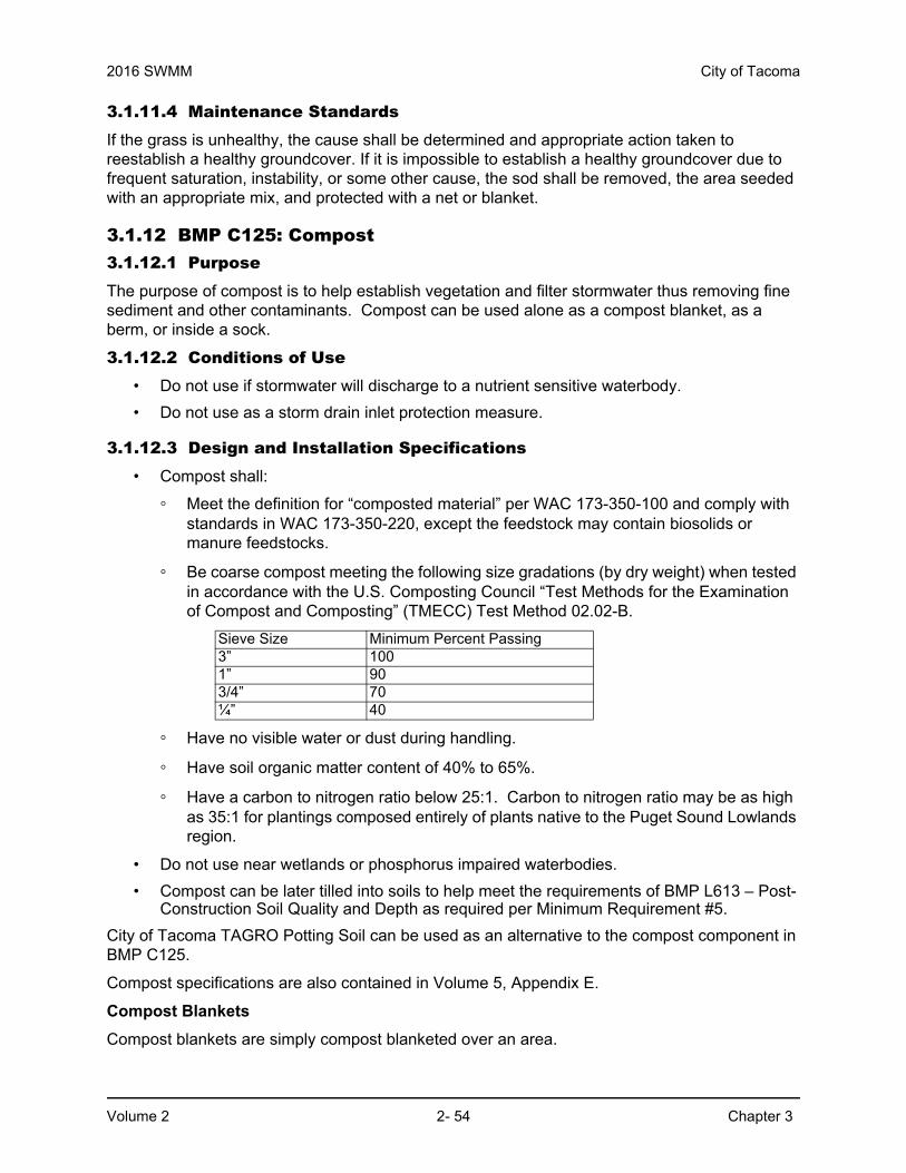
2016 SWMM City of Tacoma
Volume 2 2- 54 Chapter 3
3.1.11.4 Maintenance StandardsIf the grass is unhealthy, the cause shall be determined and appropriate action taken to reestablish a healthy groundcover. If it is impossible to establish a healthy groundcover due to frequent saturation, instability, or some other cause, the sod shall be removed, the area seeded with an appropriate mix, and protected with a net or blanket.
3.1.12 BMP C125: Compost3.1.12.1 PurposeThe purpose of compost is to help establish vegetation and filter stormwater thus removing fine sediment and other contaminants. Compost can be used alone as a compost blanket, as a berm, or inside a sock.
3.1.12.2 Conditions of Use• Do not use if stormwater will discharge to a nutrient sensitive waterbody.
• Do not use as a storm drain inlet protection measure.
3.1.12.3 Design and Installation Specifications• Compost shall:
◦ Meet the definition for “composted material” per WAC 173-350-100 and comply with standards in WAC 173-350-220, except the feedstock may contain biosolids or manure feedstocks.
◦ Be coarse compost meeting the following size gradations (by dry weight) when tested in accordance with the U.S. Composting Council “Test Methods for the Examination of Compost and Composting” (TMECC) Test Method 02.02-B.
◦ Have no visible water or dust during handling.
◦ Have soil organic matter content of 40% to 65%.
◦ Have a carbon to nitrogen ratio below 25:1. Carbon to nitrogen ratio may be as high as 35:1 for plantings composed entirely of plants native to the Puget Sound Lowlands region.
• Do not use near wetlands or phosphorus impaired waterbodies.
• Compost can be later tilled into soils to help meet the requirements of BMP L613 – Post-Construction Soil Quality and Depth as required per Minimum Requirement #5.
City of Tacoma TAGRO Potting Soil can be used as an alternative to the compost component in BMP C125.
Compost specifications are also contained in Volume 5, Appendix E.
Compost Blankets
Compost blankets are simply compost blanketed over an area.
Sieve Size Minimum Percent Passing3” 1001” 903/4” 70¼” 40
City of Tacoma 2016 SWMM
Chapter 3 2- 55 Volume 2
• Place compost 3” thick.
• Compost can be blown onto slopes up to 2:1 or spread by hand on shallower slopes.
• Compost can be mixed with a seed mix to ensure rapid vegetation.
• Compost does not need to be removed after construction phase unless required by the project engineer or geotechnical professional.
Compost Berms
Compost berms are a perimeter sediment control that can be used instead of silt fence.
• Do not use compost berms on steep slopes.
• Berm width shall be a minimum of 2 feet.
• Berm height shall be a minimum of 12 inches.
• Berm width shall be twice the berm height.
Compost can be blown in place or placed by front-end loader.
Compost should be spread over proposed landscaped section when construction is complete to aid in revegetation.
Compost Socks
Compost socks are similar to straw wattles.
• Sock material that is biodegradable will last up to 6 months and can be used for soil amendment after 6 months.
• Sock material that is non-biodegradable must be removed after construction is complete.
• Place socks perpendicular to flow.
• Walk socks in place to ensure good soil contact.
• Install wooden stakes every 12” on steep slopes or every 24” on shallow slopes
3.1.12.4 Maintenance Standards Compost Blankets
• Inspect compost regularly.
• Ensure a 3” thick blanket.
Compost Berms
• Inspect compost berm regularly.
• Ensure vehicular traffic does not cross berm and track compost offsite. If this occurs, sweep compost immediately.
Compost Socks
• Do not allow erosion or concentrated runoff under or around the barrier.
• Inspect the socks after each rainfall and repair any socks that tear or are not abutting the ground.

2016 SWMM City of Tacoma
Volume 2 2- 56 Chapter 3
3.1.13 BMP C126: Topsoiling3.1.13.1 PurposeTo provide a suitable growth medium for final site stabilization with vegetation. While not a permanent cover practice in itself, topsoiling is an integral component of providing permanent cover in those areas where there is an unsuitable soil surface for plant growth. Native soils and disturbed soils that have been organically amended not only retain much more stormwater, but they also serve as effective biofilters for urban pollutants and, by supporting more vigorous plant growth, reduce the amount of water, fertilizer, and pesticides needed to support installed landscapes. Topsoil does not include any subsoils, only the material from the top several inches, including organic debris.
Use this BMP in conjunction with other BMPs such as seeding, mulching, or sodding. This BMP is functionally equivalent to BMP L613 Post-Construction Soil Quality and Depth which is required per Minimum Requirement #5 for disturbed areas that will be developed as lawn or landscaped areas at the completed project.
3.1.13.2 Conditions of Use• Permanent landscaped areas shall contain healthy topsoil that reduces the need for
fertilizers, improves overall topsoil quality, provides for better vegetal health and vitality, improves hydrologic characteristics, and reduces the need for irrigation.
• Leave native soils and the duff layer undisturbed to the maximum extent practicable.
• To the maximum extent practical, native soils disturbed during clearing and grading shall be restored to a condition equal to or better than the original site condition’s moisture-holding capacity. Use onsite native topsoil, incorporate amendments into onsite soil, or import blended topsoil to meet this requirement.
• Topsoiling is a required procedure when establishing vegetation on shallow soils, and soils of critically low pH (high acid) levels.
• Stripping of the existing, properly functioning soil system and vegetation for the purpose of topsoiling during construction is not acceptable. If an existing soil system is functioning properly, it shall be preserved in its undisturbed and uncompacted condition.
• Depending on where the topsoil comes from, or what vegetation was on site before disturbance, invasive plant seeds may be included and could cause problems for establishing native plants, landscaped areas, or grasses.
• Topsoil from the site will contain mycorrhizal bacteria that are necessary for healthy root growth and nutrient transfer. These native mycorrhiza are acclimated to the site and will provide optimum conditions for establishing grasses. Commercially available mycorrhiza products should be used when topsoil is brought in from offsite.
3.1.13.3 Design and Installation SpecificationsIf topsoiling is to be done, the following items should be considered:
• Topsoil shall have:
◦ A minimum depth of 8-inches. Scarify subsoils below the topsoil layer at least 4-inches with some incorporation of the upper material to avoid stratified layers, where feasible. Ripping or restructuring the subgrade may also provide additional benefits regarding the overall infiltration and interflow dynamics of the soil system.

City of Tacoma 2016 SWMM
Chapter 3 2- 57 Volume 2
◦ A minimum organic content of 10% dry weight in planting beds, and 5% organic matter content in turf areas. Incorporate organic amendments to a minimum 8-inch except where tree roots or other natural features limit the depth of incorporation.
◦ A pH between 6.0 and 8.0 or matching the pH of the undisturbed soil.
• To obtain a topsoil meeting the above specifications return native topsoil to the site, import topsoil of sufficient organic content, and/or incorporate organic amendments:
◦ To meet the organic content requirements, the compost shall:
• Meet the definition for “composted material” per WAC 173-350-100 and comply with standards in WAC 173-350-220, except the feedstock may contain biosolids or manure feedstocks.
• Have no visible water or dust during handling.
• Have soil organic matter content of 40% to 65%.
• Have a carbon to nitrogen ratio below 25:1. Carbon to nitrogen ratio may be as high as 35:1 for plantings composed entirely of plants native to the Puget Sound Lowlands region.
City of Tacoma TAGRO Topsoil Mix can be used as an alternative to the compost component in BMP C125.
◦ For till soils use a mixture of approximately two parts soil to one part compost. This equates to 4 inches of compost mixed to a depth of 12 inches in till soils. Increasing the concentration of compost beyond this level can have negative effects on vegetal health, while decreasing the concentrations can reduce the benefits of amended soils.
• Mulch planting beds with 2” of organic material.
• If blended topsoil is imported, fines should be limited to 25 percent passing through a 200 sieve.
• The final composition and construction of the soil system will result in a natural selection or favoring of certain plant species over time. For example, recent practices have shown that incorporation of topsoil may favor grasses, while layering with mildly acidic, high-carbon amendments may favor more woody vegetation.
• Locate the topsoil stockpile so it meets specifications and does not interfere with work on the site. It may be possible to locate more than one pile in proximity to areas where topsoil will be used.
• Allow sufficient time in scheduling for topsoil to be spread prior to seeding, sodding, or planting.
• Do not place topsoil while in a frozen or muddy condition, when the subgrade is excessively wet, or when conditions exist that may otherwise be detrimental to proper grading or proposed sodding or seeding.
• Care must be taken not to apply topsoil over subsoil if the two soils have contrasting textures. Sandy topsoil over clayey subsoil is a particularly poor combination, as water creeps along the junction between the soil layers and causes the topsoil to slough.
• If topsoil and subsoil are not properly bonded, water will not infiltrate the soil profile evenly and it will be difficult to establish vegetation. The best method to prevent a lack of bonding is to work the topsoil into the layer below for a depth of at least 6 inches.

2016 SWMM City of Tacoma
Volume 2 2- 58 Chapter 3
• Field exploration of the site shall be made to determine if there is surface soil of sufficient quantity and quality to justify stripping. Topsoil shall be friable and loamy (loam, sandy loam, silt loam, sandy clay loam, clay loam). Areas of natural groundwater recharge should be avoided.
• Confine stripping to the immediate construction area. A 4- to 6- inch stripping depth is common, but depth may vary depending on the particular soil. Place all surface runoff control structures in place prior to stripping.
Stockpile topsoil in the following manner:
• Side slopes of the stockpile shall not exceed 2:1.
• Surround all topsoil stockpiles between October 1 and April 30 with an interceptor dike with gravel outlet and silt fence. Between May 1 and September 30, install an interceptor dike with gravel outlet and silt fence if the stockpile will remain in place for a longer period of time than active construction grading.
• Complete erosion control seeding or covering with clear plastic or other mulching materials of stockpiles within 2 days (October 1 through April 30) or 7 days (May 1 through September 30) of the formation of the stockpile. Do not cover native topsoil stockpiles with plastic.
• Topsoil shall not be placed while in a frozen or muddy condition, when the subgrade is excessively wet, or when conditions exist that may otherwise be detrimental to proper grading or proposed sodding or seeding.
• Maintain previously established grades on the areas to be topsoiled according to the approved plan.
• When native topsoil is to be stockpiled and reused, the following should apply to ensure that the mycorrhizal bacterial, earthworms, and other beneficial organisms will not be destroyed:
◦ Topsoil is to be re-installed within 4 to 6 weeks;
◦ Topsoil is not to become saturated with water;
◦ Plastic cover is not allowed.
3.1.13.4 Maintenance Standards• Inspect stockpiles regularly, especially after large storm events. Stabilize any areas that
have eroded.
• Establish soil quality and depth toward the end of the construction. Once established, protect from compaction and erosion.
• Plant and mulch soil after installation.
• Leave plant debris or its equivalent on the soil surface to replenish organic matter.
• Reduce and adjust, where possible, the use of irrigation, fertilizers, herbicides and pesticides, rather than continuing to implement formerly established practices.

City of Tacoma 2016 SWMM
Chapter 3 2- 59 Volume 2
3.1.14 BMP C127: Polyacrylamide for Soil Erosion Protection3.1.14.1 PurposePolyacrylamide (PAM) is used on construction sites to prevent soil erosion.
Applying PAM to bare soil in advance of a rain event significantly reduces erosion and controls sediment in two ways. PAM helps maintain soil structure, which increases the ability to infiltrate.
3.1.14.2 Conditions of UseDo not apply PAM directly to water or allow it to enter a water body. In areas that drain to a sediment pond, PAM can be applied to bare soil under the following conditions:
• During rough grading operations.
• Staging areas.
• Balanced cut and fill earthwork.
• Haul roads prior to placement of crushed rock surfacing.
• Compacted soil roadbase.
• Stockpiles.
• After final grade and before paving or final seeding and planting.
• Pit sites.
• Sites having a winter shut down. In the case of winter shut down, or where soil will remain unworked for several months, PAM should be used together with mulch.
3.1.14.3 Design and Installation SpecificationsPAM may be applied in dissolved form with water, or it may be applied in dry, granular or powdered form. The preferred application method is the dissolved form.
PAM is to be applied at a maximum rate of 2/3 pound PAM per 1,000 gallons water (80 mg/L) per 1 acre of bare soil. Higher concentrations of PAM do not provide any additional effectiveness.
The Preferred Method:
• Pre-measure the area where PAM is to be applied and calculate the amount of product and water necessary to provide coverage at the specified application rate (2/3 pound PAM per 1,000 gallons per acre).
• PAM is water soluble, but dissolves very slowly. Dissolve pre-measured dry granular PAM with a known quantity of clean water in a bucket several hours or overnight. Mechanical mixing will help dissolve the PAM. Always add PAM to water - not water to PAM.
• Pre-fill the water truck about 1/8 full with water. The water does not have to be potable, but it must have relatively low turbidity – in the range of 20 NTU or less.
• Add PAM and water mixture to the truck.
• Completely fill the water truck to specified volume.
• Spray PAM and water mixture onto dry soil until the soil surface is uniformly and completely wetted.
2016 SWMM City of Tacoma
Volume 2 2- 60 Chapter 3
An Alternate Method:
PAM may also be applied as a powder at the rate of 5 pounds per acre. This must be applied on a day that is dry. For areas less than 5 to 10 acres, a hand-held “organ grinder” fertilizer spreader set to the smallest setting will work. Tractor-mounted spreaders will work for larger areas.
Benefits and Limitations:
The following benefits and limitations should be considered:
• PAM shall be used in conjunction with other BMPs and not in place of other BMPs.
• Do not use PAM on a slope that flows directly into a stream or wetland or any other waterbody.
• PAM has little to no effect on sandy soils with little clay content.
• Do not add PAM to water discharging from site.
• When the total drainage area is greater than or equal to 5 acres, PAM treated areas shall drain to a sediment pond.
• Areas less than 5 acres shall drain to sediment control BMPs, such as a minimum of 3 check dams per acre. The total number of check dams used shall be maximized to achieve the greatest amount of settlement of sediment prior to discharging from the site. Each check dam shall be spaced evenly in the drainage channel through which stormwater flows are discharged offsite.
• On all sites, use silt fences to limit the discharges of sediment from the site.
• Cover and protect all areas not being actively worked from rainfall. PAM shall not be the only cover BMP used.
• PAM can be applied to wet soil, but dry soil is preferred due to less sediment loss.
• PAM will work when applied to saturated soil but is not as effective as applications to dry or damp soil.
• Keep the granular PAM supply out of the sun. Granular PAM loses its effectiveness in three months after exposure to sunlight and air.
• Proper application and re-application plans are necessary to ensure total effectiveness of PAM usage.
• PAM, combined with water, is very slippery and can be a safety hazard. Care must be taken to prevent spills of PAM powder onto paved surfaces. During an application of PAM, prevent over-spray from reaching pavement, as pavement will become slippery. If PAM powder gets on skin or clothing, wipe it off with a rough towel rather than washing with water, which makes cleanup messier and take longer.
• Some PAMs are more toxic and carcinogenic than others. Only the most environmentally safe PAM products should be used.
City of Tacoma 2016 SWMM
Chapter 3 2- 61 Volume 2
• The specific PAM copolymer formulation must be anionic. Cationic PAM shall not be used in any application because of known aquatic toxicity problems. Only the highest drinking water grade PAM, certified for compliance with ANSI/NSF Standard 60 for drinking water treatment, will be used for soil applications. PAM use shall be reviewed and approved by the City. The Washington State Department of Transportation (WSDOT) has listed approved PAM products on its web page.
http://www.wsdot.wa.gov/Environment/WaterQuality/ErosionControl.htm
• PAM designated for these uses should be "water soluble", "linear", or "non-crosslinked". Cross-linked or water absorbent PAM, polymerized in highly acidic (pH<2) conditions, are used to maintain soil moisture content.
• The PAM anionic charge density may vary from 2 to 30 percent; a value of 18 percent is typical. Studies conducted by the United States Department of Agriculture (USDA)/ARS demonstrated that soil stabilization was optimized by using very high molecular weight (12-15 mg/mole), highly anionic (>20% hydrolysis) PAM.
• PAM tackifiers are available and being used in place of guar and alpha plantago. Typically, PAM tackifiers should be used at a rate of no more than 0.5 to 1 pounds per 1,000 gallons of water in a hydromulch machine. Some tackifier product instructions say to use at a rate of 3 to 5 pounds per acre, which can be too much. In addition, pump problems can occur at higher rates due to increased viscosity.
3.1.14.4 Maintenance Standards• PAM may be reapplied on actively worked areas after a 48-hour period.
• Reapplication is not required unless PAM treated soil is disturbed or turbidity levels show the need for an additional application. If PAM treated soil is left undisturbed, a reapplication may be necessary after two months. When PAM is applied first to bare soil and then covered with straw, a reapplication may not be necessary for several months.
• Loss of sediment and PAM may be a basis for penalties per RCW 90.48.080.
3.1.15 BMP C130: Surface Roughening3.1.15.1 Purpose Surface roughening aids in the establishment of vegetative cover, reduces runoff velocity, increases infiltration, and provides for sediment trapping through the provision of a rough soil surface. Horizontal depressions are created by operating a tiller or other suitable equipment on the contour or by leaving slopes in a roughened condition by not fine grading them.
3.1.15.2 Conditions for Use• All slopes steeper than 3H:1V and greater than 5 vertical feet require surface roughening.
• Areas with grades steeper than 3H:1V should be roughened to a depth of 2 to 4 inches prior to seeding.
• Areas that will not be stabilized immediately may be roughened to reduce runoff velocity until seeding takes place.
• Slopes with a stable rock face do not require roughening.
• Slopes where mowing is planned should not be excessively roughened.
2016 SWMM City of Tacoma
Volume 2 2- 62 Chapter 3
3.1.15.3 Design and Installation Specifications• There are different methods for achieving a roughened soil surface on a slope, and the
selection of an appropriate method depends upon the type of slope. Roughening methods include stair-step grading, grooving, contour furrows, and tracking. See Figure 2 - 6 for tracking and contour furrows. Factors to be considered in choosing a method are slope steepness, mowing requirements, and whether the slope is formed by cutting or filling.
• Disturbed areas that will not require mowing may be stair-step graded, grooved, or left rough after filling.
• Stair-step grading is particularly appropriate in soils containing large amounts of soft rock. Each "step" catches material that sloughs from above, and provides a level site where vegetation can become established. Stairs should be wide enough to work with standard earth moving equipment. Stair steps must be on contour or gullies will form on the slope.
• Areas that will be mowed (these areas should have slopes less steep than 3:1) may have small furrows left by disking, harrowing, raking, or seed-planting machinery operated on the contour.
• Graded areas with slopes greater than 3:1 but less than 2:1 should be roughened before seeding. This can be accomplished in a variety of ways, including "track walking," or driving a crawler tractor up and down the slope, leaving a pattern of cleat imprints parallel to slope contours.
• Tracking is done by operating equipment up and down the slope to leave horizontal depressions in the soil.
3.1.15.4 Maintenance Standards• Areas that are graded in this manner should be seeded as quickly as possible.
• Regular inspections should be made of the area. If rills appear, they should be re-graded and re-seeded immediately.

City of Tacoma 2016 SWMM
Chapter 3 2- 63 Volume 2
Figure 2 - 6. Surface Roughening by Tracking and Contour Furrows
3.1.16 BMP C131: Gradient Terraces3.1.16.1 Purpose Gradient terraces reduce erosion damage by intercepting surface runoff and conducting it to a stable outlet at a non-erosive velocity.

2016 SWMM City of Tacoma
Volume 2 2- 64 Chapter 3
3.1.16.2 Conditions of UseGradient terraces normally are limited to denuded land having a water erosion problem. They should not be constructed on deep sands or on soils that are too stony, steep, or shallow to permit practical and economical installation and maintenance. Gradient terraces may be used only where suitable outlets are or will be made available. See Figure 2 - 7 for gradient terraces.
3.1.16.3 Design and Installation SpecificationsThe maximum vertical spacing of gradient terraces should be determined by the following method:
VI= (0.8)s + y
Where:
VI = vertical interval in feet
s= land rise per 100 feet, expressed in feet
y= a soil and cover variable with values from 1.0 to 4.0
Values of “y” are influenced by soil erodibility and cover practices. The lower values are applicable to erosive soils where little to no residue is left on the surface. The higher value is applicable only to erosion-resistant soils where a large amount of residue (1½ tons of straw/acre equivalent) is on the surface.
• The minimum constructed cross-section should meet the design dimensions.
• The top of the constructed ridge should not be lower at any point than the design elevation plus the specified overfill for settlement. The opening at the outlet end of the terrace should have a cross section equal to that specified for the terrace channel.
• Channel grades may be either uniform or variable with a maximum grade of 0.6 feet per 100 feet length. For short distances, terrace grades may be increased to improve alignment. The channel velocity should not exceed that which is non-erosive for the soil type with the planned treatment.
• All gradient terraces should have adequate outlets. Such an outlet may be a grassed waterway, vegetated area, or tile outlet. In all cases, the outlet must convey runoff from the terrace or terrace system to a point where the outflow will not cause damage. Vegetative cover should be used in the outlet channel.
• The design elevation of the water surface of the terrace should not be lower than the design elevation of the water surface in the outlet at their junction, when both are operating at design flow.
• Vertical spacing determined by the above methods may be increased as much as 0.5 feet or 10 percent, whichever is greater, to provide better alignment or location, avoid obstacles, adjust for equipment size, or reach a satisfactory outlet.
• The drainage area above the top should not exceed the area that would be drained by a terrace with normal spacing.
• The terrace should have enough capacity to handle the peak runoff expected from a 2-year, 24-hour design storm without overtopping.
• The terrace cross-section should be proportioned to fit the land slope. The ridge height should include a reasonable settlement factor. The ridge should have a minimum top width of 3 feet at the design height. The minimum cross-sectional area of the terrace channel should be 8 square feet for land slopes of 5 percent or less, 7 square feet for
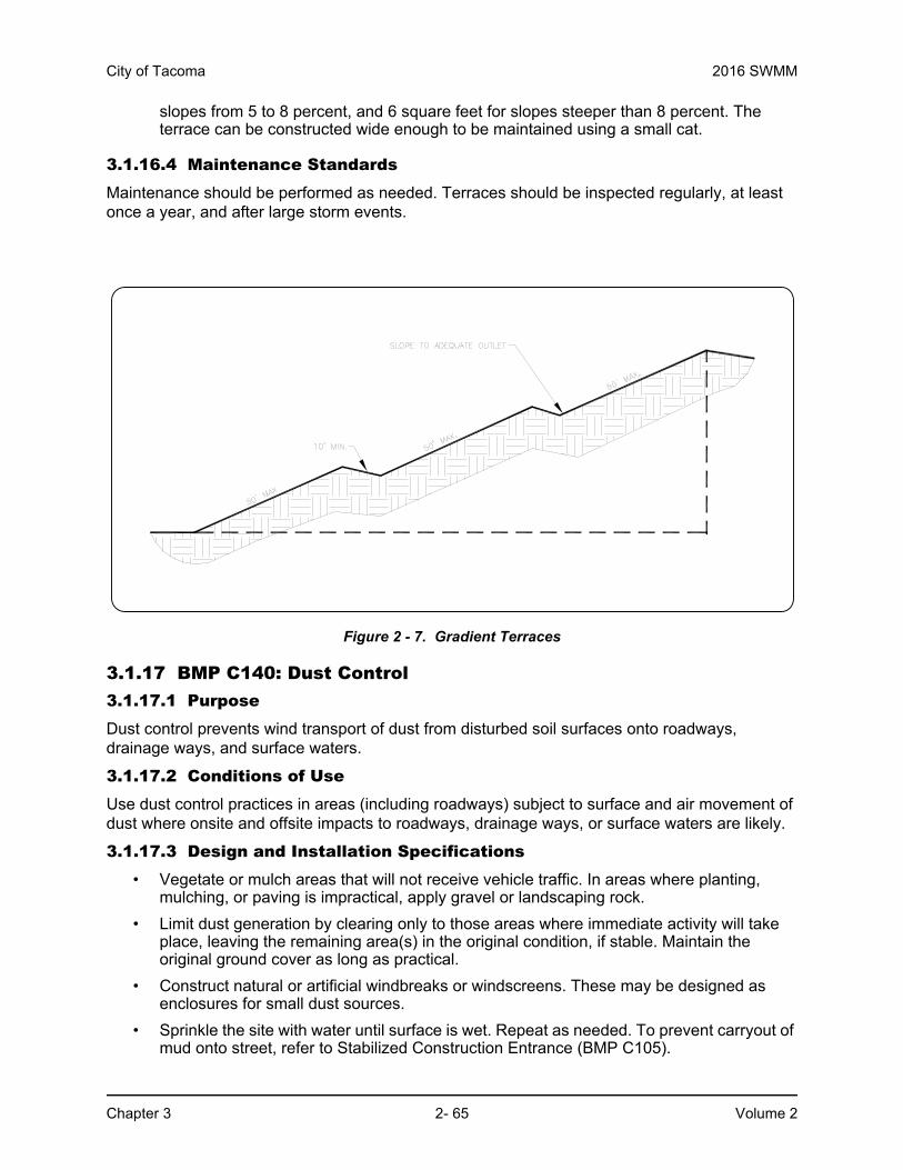
City of Tacoma 2016 SWMM
Chapter 3 2- 65 Volume 2
slopes from 5 to 8 percent, and 6 square feet for slopes steeper than 8 percent. The terrace can be constructed wide enough to be maintained using a small cat.
3.1.16.4 Maintenance StandardsMaintenance should be performed as needed. Terraces should be inspected regularly, at least once a year, and after large storm events.
Figure 2 - 7. Gradient Terraces
3.1.17 BMP C140: Dust Control 3.1.17.1 Purpose Dust control prevents wind transport of dust from disturbed soil surfaces onto roadways, drainage ways, and surface waters.
3.1.17.2 Conditions of UseUse dust control practices in areas (including roadways) subject to surface and air movement of dust where onsite and offsite impacts to roadways, drainage ways, or surface waters are likely.
3.1.17.3 Design and Installation Specifications• Vegetate or mulch areas that will not receive vehicle traffic. In areas where planting,
mulching, or paving is impractical, apply gravel or landscaping rock.
• Limit dust generation by clearing only to those areas where immediate activity will take place, leaving the remaining area(s) in the original condition, if stable. Maintain the original ground cover as long as practical.
• Construct natural or artificial windbreaks or windscreens. These may be designed as enclosures for small dust sources.
• Sprinkle the site with water until surface is wet. Repeat as needed. To prevent carryout of mud onto street, refer to Stabilized Construction Entrance (BMP C105).

2016 SWMM City of Tacoma
Volume 2 2- 66 Chapter 3
• Irrigation water can be used for dust control. Install irrigation systems as a first step on sites where dust control is a concern.
• Spray exposed soil areas with a dust palliative, following the manufacturer’s instructions and cautions regarding handling and application. Used oil is prohibited from use as a dust suppressant. The City may approve other dust palliatives such as calcium chloride or PAM.
• PAM (BMP C127) added to water at a rate of 2/3 pounds per 1,000 gallons of water per acre and applied from a water truck is more effective than water alone. This is due to the increased infiltration of water into the soil and reduced evaporation. In addition, small soil particles are bonded together and are not as easily transported by wind. Adding PAM may actually reduce the quantity of water needed for dust control. There are concerns with the proper use of PAM, refer to BMP C127 for more information on PAM application. PAM use requires COT approval.
• Lower speed limits. High vehicle speed increases the amount of dust stirred up from unpaved roads and lots.
• Upgrade the road surface strength by improving particle size, shape, and mineral types that make up the surface and base materials.
• Add surface gravel to reduce the source of dust emission. Limit the amount of fine particles to 10 to 20 percent.
• Use geotextile fabrics to increase the strength of new roads or roads undergoing reconstruction.
• Encourage the use of alternate, paved routes, if available.
• Restrict use of paved roadways by tracked vehicles and heavy trucks to prevent damage to road surfaces and bases.
• Apply chemical dust suppressants using the admix method, blending the product with the top few inches of surface material. Suppressants may also be applied as surface treatments.
• Pave unpaved permanent roads and other trafficked areas.
• Use vacuum street sweepers.
• Remove mud and other dirt promptly so it does not dry and then turn into dust.
• Limit dust-causing work on windy days.
• Contact the Puget Sound Clean Air Agency for guidance and training on other dust control measures. Compliance with the Puget Sound Clean Air Agency’s recommendations/requirements constitutes compliance with this BMP.
3.1.17.4 Maintenance StandardsEvaluate the potential for dust generation frequently during dry periods. Complete the actions outlined above as needed to limit the dust.
Any dust which leaves the site must be cleaned immediately.
3.1.18 BMP C150: Materials On Hand3.1.18.1 PurposeQuantities of erosion prevention and sediment control materials should be kept on the project site at all times to be used for regular maintenance and emergency situations such as unexpected

City of Tacoma 2016 SWMM
Chapter 3 2- 67 Volume 2
heavy summer rains. Having these materials onsite reduces the time needed to implement BMPs when inspections indicate that existing BMPs are not meeting the Construction SWPPP requirements.
3.1.18.2 Conditions of UseConstruction projects of any size or type can benefit from having materials on hand. A small commercial development project could have a roll of plastic and some gravel available for immediate protection of bare soil and temporary berm construction. A large earthwork project, such as highway construction, might have several tons of straw, several rolls of plastic, flexible pipe, sandbags, geotextile fabric, and steel “T” posts.
• Materials are stockpiled and readily available before any site clearing, grubbing, or earthwork begins. A large contractor or developer could keep a stockpile of materials that are available to be used on several projects.
• If storage space at the project site is at a premium, the contractor could maintain the materials at a location less than one hour from the project site.
3.1.18.3 Design and Installation SpecificationsDepending on project type, size, complexity, and length, materials and quantities will vary. Table 2 - 9 provides a good minimum that will cover numerous situations.
3.1.18.4 Maintenance Standards • All materials with the exception of the quarry spalls, steel “T” posts, and gravel should be
kept covered and out of both sun and rain.
• Re-stock materials used as needed.
3.1.19 BMP C151: Concrete Handling3.1.19.1 PurposeConcrete work can generate process water and slurry that contain fine particles and high pH, both of which can violate water quality standards in the receiving water. This BMP is intended to minimize and eliminate concrete, concrete process water and concrete slurry from entering waters of the state.
Table 2 - 9: Materials on Hand
Material Measure Quantity
Clear Plastic, 6 mil 100 foot roll 1-2
Drainpipe, 6 or 8 inch diameter 25 foot section 4-6
Sandbags, filled each 25-50
Quarry Spalls ton 2-4
Washed Gravel cubic yard 2-4
Geotextile Fabric 100 foot roll 1-2
Catch Basin Inserts each 2-4
Steel “T” Posts each 12-24
2016 SWMM City of Tacoma
Volume 2 2- 68 Chapter 3
3.1.19.2 Conditions of UseUtilize these management practices any time concrete is used.
Concrete construction projects include, but are not limited to, the following:
• Curbs
• Sidewalks
• Roads
• Bridges
• Foundations
• Floors
• Runways
3.1.19.3 Design and Installation Specifications• Concrete trucks, chutes, pumps, and internals shall be washed out only at an approved
offsite location or in designated washout areas.
• Unused concrete remaining in the truck and pump shall be returned to the originating batch plant for recycling.
• Hand tools shall be washed off only into formed areas awaiting installation of concrete or asphalt.
• Equipment that cannot be easily moved, such as concrete pavers, shall only be washed in areas that do not directly drain to natural or constructed stormwater conveyances.
• Washdown from areas such as concrete aggregate driveways shall not drain directly to natural or constructed stormwater conveyances.
• Do not wash out concrete trucks onto the ground, or into storm drains, open ditches, streets, or streams. Refer to BMP C151 for information concerning concrete handling and BMP C154 for information concerning concrete washout areas.
• Always use forms or solid barriers for concrete pours within 15-feet of surface waters.
• Refer to BMPs C252 and C253 for pH adjustment requirements.
• Refer to the Construction Stormwater General Permit for pH monitoring requirements if the project involves one of the following activities:
◦ Significant concrete work (greater than 1,000 cubic yards poured concrete or recycled concrete used over the life of a project).
◦ The use of engineered soils amended with (but not limited to) Portland cement-treated base, cement kiln dust or fly ash.
◦ Discharging stormwater to segments of water bodies on the 303(d) list (Category 5) for high pH.
3.1.19.4 Maintenance StandardsContainers shall be checked for holes in the liner daily during concrete pours and repaired the same day.

City of Tacoma 2016 SWMM
Chapter 3 2- 69 Volume 2
3.1.20 BMP C152: Sawcutting and Surfacing Pollution Prevention3.1.20.1 PurposeSawcutting and surfacing operations generate slurry and process water that contains fine particles and high pH (concrete cutting), both of which can violate water quality standards in the receiving water. This BMP is intended to minimize and eliminate process water and slurry from entering waters of the State
3.1.20.2 Conditions of UseAnytime sawcutting or surfacing operations take place, use these management practices. Sawcutting and surfacing operations include, but are not limited to, the following:
• Sawing
• Coring
• Grinding
• Roughening
• Hydro-demolition
• Bridge and road surfacing
3.1.20.3 Design and Installation Specifications• Vacuum slurry and cuttings during cutting and surfacing operations.
• Do not leave slurry and cuttings on permanent concrete or asphalt pavement overnight.
• Do not drain slurry and cuttings to any natural or constructed drainage conveyance.
• Dispose of collected slurry and cuttings in a manner that does not violate groundwater or surface water quality standards.
• Do not drain process water that is generated during hydro-demolition, surface roughening, or similar operations to any natural or constructed drainage conveyance. Dispose of process water in a manner that does not violate groundwater or surface water quality standards.
• Handle and dispose of cleaning waste material and demolition debris in a manner that does not cause contamination of water. If the area is swept with a pick-up sweeper, haul the material out of the area to an appropriate disposal site.
3.1.20.4 Maintenance StandardsContinually monitor operations to determine whether slurry, cuttings, or process water could enter waters of the state. If inspections show that a violation of water quality standards could occur, stop operations and immediately implement preventive measures such as berms, barriers, secondary containment, and vacuum trucks.
3.1.21 BMP C153: Material Delivery, Storage and Containment3.1.21.1 PurposePrevent, reduce, or eliminate the discharge of pollutants from material delivery and storage to the stormwater system or watercourses by minimizing the storage of hazardous materials onsite, storing materials in a designated area, and installing secondary containment.
2016 SWMM City of Tacoma
Volume 2 2- 70 Chapter 3
3.1.21.2 Conditions of UseThese procedures are suitable for use at all construction sites with delivery and storage of the following materials:
• Petroleum products such as fuel, oil, and grease
• Soil stabilizers and binders (e.g. Polyacrylamide)
• Fertilizers, pesticides, and herbicides
• Detergents
• Asphalt and concrete compounds
• Hazardous chemicals such as acids, lime, adhesives, paints, solvents, and curing compounds
• Any other material that may be detrimental if released to the environment
3.1.21.3 Design and Installation SpecificationsThe following steps should be taken to minimize risk:
• Locate temporary storage area away from vehicular traffic, near the construction entrance(s), and away from waterways or storm drains.
• Supply Material Safety Data Sheets (MSDS) for all materials stored. Keep chemicals in their original labeled containers.
• Surrounding materials with earth berms is an option for temporary secondary containment.
• Minimize hazardous material storage onsite.
• Handle hazardous materials as infrequently as possible.
• During the wet weather season (October 1 through April 30), consider storing materials in a covered area.
• Store materials in secondary containment, such as an earthen dike, a horse trough, or a children’s wading pool for non-reactive materials such as detergents, oil, grease, and paints. “Bus boy” trays or concrete mixing trays may be used as secondary containment for small amounts of material.
• Do not store chemicals, drums, or bagged materials directly on the ground. Place these items on a pallet and, when possible, in secondary containment.
• If drums cannot be stored under a roof, domed plastic covers are inexpensive and snap to the top of drums, preventing water from collecting.
3.1.21.4 Material Storage Areas and Secondary Containment Practices:• Store liquids, petroleum products, and substances listed in 40 CFR Parts 110, 117, or
302 in approved containers and drums and do not overfill the containers or drums. Store containers and drums in temporary secondary containment facilities.
• Temporary secondary containment facilities shall provide for a spill containment volume able to contain precipitation from a 25 year, 24 hour storm event plus 10% of the total enclosed container volume of all containers, or 110% of the capacity of the largest container within its boundary, whichever is greater.
City of Tacoma 2016 SWMM
Chapter 3 2- 71 Volume 2
• Secondary containment facilities shall be impervious to the materials stored therein for a minimum contact time of 72 hours.
• Secondary containment facilities shall be maintained free of accumulated rainwater and spills. In the event of spills or leaks, collect accumulated rainwater and spills and place into drums. Handle these liquids as hazardous waste unless testing determines them to be non-hazardous. Dispose of all wastes properly.
• Provide sufficient separation between stored containers to allow for spill cleanup and emergency response access.
• During the wet weather season (October 1 through April 30), cover each secondary containment facility during non-working days, prior to and during rain events.
• Keep material storage areas clean, organized, and equipped with an ample supply of appropriate spill clean-up material.
• The spill kit should include, at a minimum:
◦ 1 water resistant nylon bag
◦ 3 oil absorbent socks (3-inches by 4-feet)
◦ 2 oil absorbent socks (3-inches by 10-feet)
◦ 12 oil absorbent pads (17-inches by 19-inches)
◦ 1 pair splash resistant goggles
◦ 3 pairs nitrile gloves
◦ 10 disposable bags with ties
◦ Instructions
3.1.21.5 MaintenanceAny stormwater within the material storage area shall be pumped or otherwise discharged after each rain event. Before pumping, the stormwater must be evaluated to determine if it must go to treatment or can be discharged without treatment. If stormwater is contaminated, direct the discharge to appropriate treatment.
3.1.22 BMP C154: Concrete Washout Area3.1.22.1 PurposePrevent or reduce the discharge of pollutants to stormwater from concrete waste by conducting washout offsite, or performing onsite washout in a designated area to prevent pollutants from entering surface waters or groundwater.
3.1.22.2 Conditions of UseUse concrete washout best management practices on construction projects where:
• It is not possible to dispose of all concrete wastewater and washout offsite (ready mix plant, etc.)
• Concrete trucks, pumpers, or other concrete coated equipment are washed onsite.

2016 SWMM City of Tacoma
Volume 2 2- 72 Chapter 3
NOTE: If less than 3 concrete trucks or pumpers need to be washed onsite, the washwater may be disposed of in a formed area awaiting concrete. Do not allow dirty water to enter storm drains, open ditches, or any waterbody.
3.1.22.3 Implementation• Perform washout of concrete trucks offsite or in designated concrete washout areas only.
• Do not wash out concrete trucks onto the ground, or into storm drains, open ditches, streets, or streams.
• Do not allow excess concrete to be dumped onsite, except in designated concrete washout areas.
• Concrete washout areas may be prefabricated concrete washout containers, or self-installed structures (above-grade or below-grade).
◦ Prefabricated containers are most resistant to damage and protect against spills and leaks. Companies may offer delivery service and provide regular maintenance and disposal of solid and liquid waste.
◦ If self-installed concrete washout areas are used, below-grade structures are preferred over above-grade structures because they are less prone to spills and leaks.
◦ Self-installed above-grade structures should only be used if excavation is not practical.
• Identify concrete washout area on the TESC plan.
3.1.22.4 Education• Discuss the concrete management techniques described in this BMP with the ready-mix
concrete supplier before any deliveries are made.
• Educate employees and subcontractors on the concrete waste management techniques described in this BMP.
• Install a sign adjacent to each temporary concrete washout facility to inform concrete equipment operators to utilize the proper facilities.
3.1.22.5 Location and Placement Considerations: • Locate washout area or temporary concrete washout facilities at least 50 feet from
sensitive areas such as storm drains, open ditches, or water bodies, including wetlands.
• Allow convenient access for concrete trucks, preferably near the area where the concrete is being poured.
• If trucks need to leave a paved area to access washout, prevent track-out with a pad of rock or quarry spalls (BMP C105). These areas should be far enough away from other construction traffic to reduce the likelihood of accidental damage and spills.
• The washout area volume installed should depend on the expected demand for storage capacity.
• On large sites with extensive concrete work, washouts may be placed in multiple locations for ease of use by concrete truck drivers.

City of Tacoma 2016 SWMM
Chapter 3 2- 73 Volume 2
3.1.22.6 Onsite Temporary Concrete Washout Facility, Transit Truck Washout Procedures:
• Locate temporary washout facilities at least 50 feet from sensitive areas including storm drain inlets, open drainage facilities, and surface waterbodies.
• Construct and maintain concrete washout facilities in order to contain all liquid and concrete waste generated by washout operations.
◦ Approximately 7 gallons of wash water are used to wash one truck chute.
◦ Approximately 50 gallons are used to wash out the hopper of a concrete pump truck.
• Washout of concrete trucks shall be performed in designated areas only.
• Concrete washout from concrete pumper bins can be washed into concrete pumper trucks and discharged into designated washout area or properly disposed of offsite.
• Once concrete wastes are washed into the designated area and allowed to harden, the concrete should be broken up, removed, and disposed of per applicable solid waste regulations. Dispose of hardened concrete on a regular basis.
Temporary Above-Grade Concrete Washout Facility
• Temporary concrete washout facility (type above grade) should be constructed as shown on the details at the end of this BMP, with a recommended minimum length and minimum width of 10 ft, but with sufficient quantity and volume to contain all liquid and concrete waste generated by washout operations.
• Plastic lining material should be a minimum of 10 mil polyethylene sheeting and should be free of holes, tears, or other defects that compromise the impermeability of the material.

2016 SWMM City of Tacoma
Volume 2 2- 74 Chapter 3
Temporary Below-Grade Concrete Washout Facility
• Temporary concrete washout facilities (type below grade) should be constructed as shown on the details at the end of this BMP, with a recommended minimum length and minimum width of 10 ft. The quantity and volume should be sufficient to contain all liquid and concrete waste generated by washout operations.
• Lath and flagging should be commercial type.
• Plastic lining material shall be a minimum of 10 mil polyethylene sheeting and should be free of holes, tears, or other defects that compromise the impermeability of the material.
• Liner seams shall be installed in accordance with manufacturers’ recommendations.
• Soil base shall be prepared free of rocks or other debris that may cause tears or holes in the plastic lining material.
3.1.22.7 Inspection and Maintenance• Inspect and verify that concrete washout BMPs are in place prior to the commencement
of concrete work.
• During periods of concrete work, inspect daily to verify continued performance.
◦ Check overall condition and performance.
◦ Check remaining capacity (% full).
◦ If using self-installed washout facilities, verify plastic liners are intact and sidewalls are not damaged.
◦ If using prefabricated containers, check for leaks.
• Maintain washout facilities to provide adequate holding capacity with a minimum freeboard of 12 inches.
• Washout facilities must be cleaned, or new facilities must be constructed and ready for use once the washout is 75% full.
• If the washout is nearing capacity, vacuum and dispose of the waste material in an approved manner.
◦ Do not discharge liquid or slurry to waterways, storm drains or directly onto ground.
◦ Do not use sanitary sewer without obtaining a City of Tacoma Special Approved Discharge permit. Call Source Control at 253.591.5588 for more information.
◦ Place a secure, non-collapsing, non-water collecting cover over the concrete washout facility prior to predicted wet weather to prevent accumulation and overflow of precipitation.
◦ Remove and dispose of hardened concrete and return the structure to a functional condition. Concrete may be reused onsite or hauled away for disposal or recycling.
• When you remove materials from the self-installed concrete washout, build a new structure; or, if the previous structure is still intact, inspect for signs of weakening or damage, and make any necessary repairs. Re-line the structure with new plastic after each cleaning.
City of Tacoma 2016 SWMM
Chapter 3 2- 75 Volume 2
3.1.22.8 Removal of Temporary Concrete Washout Facilities• When temporary concrete washout facilities are no longer required for the work, remove
and properly dispose of the hardened concrete, slurries and liquids.
• Remove materials used to construct temporary concrete washout facilities from the site of the work and dispose of or recycle it.
• Holes, depressions or other ground disturbance caused by the removal of the temporary concrete washout facilities shall be backfilled, repaired, and stabilized to prevent erosion.

2016 SWMM City of Tacoma
Volume 2 2- 76 Chapter 3
.
Figure 2 - 8. Temporary Concrete Washout Facility

City of Tacoma 2016 SWMM
Chapter 3 2- 77 Volume 2
Figure 2 - 9. Prefabricated Concrete Washout Container with Ramp
3.1.23 BMP C160: Erosion and Sediment Control Lead3.1.23.1 PurposeThe project proponent designates at least one person as the responsible representative in charge of erosion and sediment control (ESC) and water quality protection. The designated person shall be the erosion and sediment control (ESC) lead, who is responsible for ensuring compliance with all local, state, and federal erosion and sediment control and water quality requirements.
3.1.23.2 Conditions of Use• An erosion and sediment control contact is required for all project sites.
• A certified erosion and sediment control lead (CESCL) or certified professional in erosion and sediment control (CPESC) is required on projects that include, but are not limited to:
◦ Construction activity that disturbs one acre of land or more.
◦ Construction activity that disturbs less than one acre of land, but is part of a larger common plan of development or sale that will ultimately disturb one acre of land or more.

2016 SWMM City of Tacoma
Volume 2 2- 78 Chapter 3
◦ Heavy construction of roads, bridges, highways, airports, buildings.
◦ Projects near wetlands and sensitive or critical areas.
◦ Projects in or over water.
• Projects disturbing less than one acre must have an Erosion Sediment Control Lead (ESC) conduct inspections. The ESC Lead does not have to have CESCL or CPESC certification.
• The CESCL, CPESC, or ESC Lead shall be identified in the SWPPP and shall be onsite or on-call at all times.
• The CESCL, CPESC, or ESC Lead must be knowledgeable in the principles and practices of erosion and sediment control and have the skills to assess:
◦ Site conditions and construction activities that could impact the quality of stormwater.
◦ Effectiveness of erosion and sediment control measures used to control the quality of stormwater discharges.
3.1.23.3 Specifications• The CESCL lead shall:
◦ Have a current certified erosion and sediment control lead (CESCL) certificate proving attendance in an erosion and sediment control training course that meets the minimum ESC training and certification requirements established by Ecology. Ecology will maintain a list of ESC training and certification providers at: www.ecy.wa.gov/programs/wq/stormwater.
• For additional information concerning the Certified Professional in Erosion and Sediment Control program please go to www.cpesc.net.
• The ESC lead shall have authority to act on behalf of the contractor or developer and shall be available, on call, 24 hours per day throughout the period of construction.
• The Construction SWPPP shall include the name, telephone number, email, and address of the designated ESC lead.
• An ESC lead may provide inspection and compliance services for multiple construction projects in the same geographic region.
• Duties and responsibilities of the ESC lead shall include, but are not limited to, the following:
◦ Inspecting all areas disturbed by construction activities, all BMPs and all stormwater discharge points at least once every calendar week and within 24 hours of any discharge from the site. The ESC lead may reduce the inspection frequency for temporary stabilized, inactive sites to monthly.
◦ Examining stormwater visually for the presence of suspended sediment, turbidity, discoloration, and oil sheen.
◦ Evaluating the effectiveness of BMPs.
◦ Maintaining a permit file on site at all times which includes the SWPPP and any associated permits and plans.
◦ Directing BMP installation, inspection, maintenance, modification, and removal.

City of Tacoma 2016 SWMM
Chapter 3 2- 79 Volume 2
◦ Updating all project drawings and the Construction SWPPP with changes made.
◦ Keeping daily logs and inspection reports. Inspection reports should include:
• Inspection date/time.
• Weather information, general conditions during inspection, and approximate amount of precipitation since the last inspection.
• A summary or list of all BMPs implemented, including observations of all erosion/sediment control structures or practices. The following shall be noted:
◦Locations of BMPs inspected,
◦Locations of BMPs that need maintenance,
◦Locations of BMPs that failed to operate as designed or intended, and
◦Locations where additional or different BMPs are required.
• Visual monitoring results, including a description of discharged stormwater. The presence of suspended sediment, turbid water, discoloration, and oil sheen shall be noted, as applicable.
• Any water quality monitoring performed during inspection.
• General comments and notes, including a brief description of any BMP repairs, maintenance, or installations made as a result of the inspection.
◦ Facilitate, participate in, and take corrective actions resulting from inspections performed by outside agencies or the owner.
◦ Keep an inventory of equipment onsite.
3.1.24 BMP C161: Payment of Erosion Control Work3.1.24.1 PurposeAs with any construction operation, the contractor should be paid for erosion control work. Address payment for erosion control during project development and design. Identify the method of payment in the SWPPP.
Erosion control work should never be “incidental” to the contract as it is extremely difficult for the contractor to bid the work.
3.1.25 BMP C162: Scheduling3.1.25.1 PurposeSequencing a construction project reduces the amount and duration of soil exposed to erosion by wind, rain, runoff, and vehicle tracking.
3.1.25.2 Conditions of UseThe construction sequence schedule is an orderly listing of all major land-disturbing activities together with the necessary erosion and sedimentation control measures planned for the project.

2016 SWMM City of Tacoma
Volume 2 2- 80 Chapter 3
This type of schedule guides the contractor on work to be done before other work is started so serious erosion and sedimentation problems can be avoided.
Following a specified work schedule that coordinates the timing of land-disturbing activities and the installation of control measures is perhaps the most cost-effective way of controlling erosion during construction. The removal of surface ground cover leaves a site vulnerable to accelerated erosion. Construction procedures that limit land clearing, provide timely installation of erosion and sedimentation controls, and restore protective cover quickly can significantly reduce the erosion potential of a site.
3.1.25.3 Design Considerations• Minimize construction during rainy periods.
• Schedule projects to disturb only small portions of the site at any one time. Complete grading as soon as possible. Immediately stabilize the disturbed portion before grading the next portion. Practice staged seeding in order to revegetate cut and fill slopes as the work progresses.
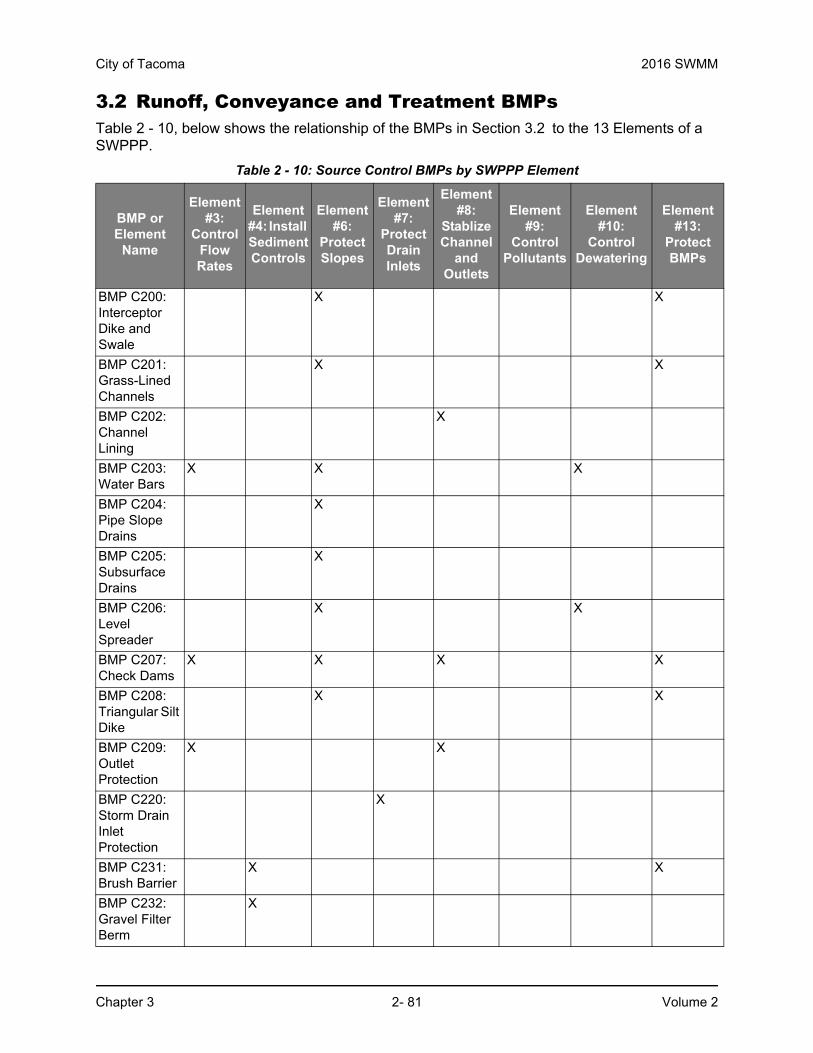
City of Tacoma 2016 SWMM
Chapter 3 2- 81 Volume 2
3.2 Runoff, Conveyance and Treatment BMPsTable 2 - 10, below shows the relationship of the BMPs in Section 3.2 to the 13 Elements of a SWPPP.
Table 2 - 10: Source Control BMPs by SWPPP Element
BMP or Element
Name
Element #3:
Control Flow Rates
Element #4: Install Sediment Controls
Element #6:
Protect Slopes
Element #7:
Protect Drain Inlets
Element #8:
Stablize Channel
and Outlets
Element #9:
Control Pollutants
Element #10:
Control Dewatering
Element #13:
Protect BMPs
BMP C200: Interceptor Dike and Swale
X X
BMP C201: Grass-Lined Channels
X X
BMP C202: Channel Lining
X
BMP C203: Water Bars
X X X
BMP C204: Pipe Slope Drains
X
BMP C205: Subsurface Drains
X
BMP C206: Level Spreader
X X
BMP C207: Check Dams
X X X X
BMP C208: Triangular Silt Dike
X X
BMP C209: Outlet Protection
X X
BMP C220: Storm Drain Inlet Protection
X
BMP C231: Brush Barrier
X X
BMP C232: Gravel Filter Berm
X

2016 SWMM City of Tacoma
Volume 2 2- 82 Chapter 3
3.2.1 BMP C200: Interceptor Dike and Swale3.2.1.1 PurposeProvide a ridge of compacted soil, or a ridge with an upslope swale, at the top or base of a disturbed slope or along the perimeter of a disturbed construction area to convey stormwater. Use the dike and/or swale to intercept the runoff from unprotected areas and direct it to areas
BMP C233: Silt Fence
X X
BMP C234: Vegetated Strip
X X
BMP C235: Wattles
X X
BMP C236: Vegetated Filtration
X
BMP C240: Sediment Trap
X X
BMP C241: Temporary Sediment Pond
X X
BMP C250: Construction Stormwater Chemical Treatment
X X
BMP C251: Construction Stormwater Filtration
X X
BMP C252: High pH Neutralization Using CO2
X
BMP C253: pH Control for High pH Water
X
BMP or Element
Name
Element #3:
Control Flow Rates
Element #4: Install Sediment Controls
Element #6:
Protect Slopes
Element #7:
Protect Drain Inlets
Element #8:
Stablize Channel
and Outlets
Element #9:
Control Pollutants
Element #10:
Control Dewatering
Element #13:
Protect BMPs

City of Tacoma 2016 SWMM
Chapter 3 2- 83 Volume 2
where erosion can be controlled. This can prevent storm runoff from entering the work area or sediment-laden runoff from leaving the construction site.
3.2.1.2 Conditions of UseWhere the runoff from an exposed site or disturbed slope must be conveyed to an erosion control facility that can safely convey the stormwater.
• Locate upslope of a construction site to prevent runoff from entering disturbed area.
• When placed horizontally across a disturbed slope, it reduces the amount and velocity of runoff flowing down the slope.
• Locate downslope to collect runoff from a disturbed area and direct it to a sediment basin.
3.2.1.3 Design and Installation Specifications• Stabilize dike and/or swale and channel with temporary or permanent vegetation or other
channel protection during construction.
• If the design velocity of a channel to be vegetated by seeding exceeds 2 ft/sec, a temporary channel liner is required. See Figure 2 - 11.
• Channel requires a positive grade for drainage; steeper grades require channel protection and check dams.
• Review construction for areas where overtopping may occur.
• Should be used at the top of new fill before vegetation is established.
• May be used as a permanent diversion channel to carry the runoff.
• Sub-basin tributary area should be one acre or less.
• Design capacity for the peak flow from a 10-year, 24-hour storm event assuming a Type 1A rainfall distribution (3-inches) for temporary facilities. Alternatively, use the 10-year return period flowrate, indicated by WWHM assuming a 15 minute timestep. Design capacity for the peak flow from a 25-year, 24-hour storm for permanent facilities.

2016 SWMM City of Tacoma
Volume 2 2- 84 Chapter 3
Interceptor Dikes
• Interceptor dikes shall meet the following criteria:
• Horizontal Spacing of Interceptor Dikes:
• Stabilization depends on velocity and reach.
• The upslope side of the dike shall provide positive drainage to the dike outlet. No erosion shall occur at the outlet. Provide energy dissipation measures as necessary. Sediment-laden runoff must be released through a sediment trapping facility.
• Minimize construction traffic over temporary dikes. Use temporary cross culverts for channel crossing.
Interceptor Swales
• Interceptor swales shall meet the following criteria:
• Inspect diversion dikes and interceptor swales once a week and after every rainfall. Immediately remove sediment from the flow area.
• Repair damage caused by construction traffic or other activity before the end of each working day.
• Check outlets and make timely repairs as needed to avoid gully formation. When the area below the temporary diversion dike is permanently stabilized, remove the dike and fill and stabilize the channel to blend with the natural surface.
Top Width 2 feet minimum.Height 1.5 feet minimum on berm.Side Slope 2:1 or flatter.Grade Depends on topography, however, dike system minimum is
0.5% and maximum is 1%Compaction Minimum of 90 percent ASTM D698 standard proctor.
Average Slope Slope Percent Flowpath Length20H:1V or less 3-5% 300 feet(10 to 20)H:1V 5-10% 200 feet(4 to 10)H:1V 10-25% 100 feet(2 to 4)H:1V 25-50% 50 feet
Slopes <5% Seed and mulch applied within 5 days of dike construction (see BMP C121, Mulching).
Slopes 5 - 40% Dependent on runoff velocities and dike materials. Stabilization should be done immediately using either sod or riprap or other measures to avoid erosion. See Volume 3, Section 3.4 for additional guidance on channel protection.
Bottom Width 2 feet minimum; the bottom shall be level.Depth 1-foot minimum.Side Slope 2H:1V or flatterGrade Maximum 5 percent, with positive drainage to a suitable outlet
(such as a sediment pond).Stabilization Seed as per BMP C120, Temporary and Permanent Seeding,
or BMP C202, Channel Lining, 12 inches thick of riprap pressed into the bank and extending at least 8 inches vertical from the bottom.
City of Tacoma 2016 SWMM
Chapter 3 2- 85 Volume 2
3.2.2 BMP C201: Grass-Lined Channels3.2.2.1 PurposeTo provide a channel with a vegetative lining for conveyance of runoff. See Figure 2 - 10 for typical grass-lined channels.
3.2.2.2 Conditions of UseThis practice applies to construction sites where concentrated runoff needs to be contained to prevent erosion or flooding.
• When a vegetative lining can provide sufficient stability for the channel cross section and lower velocities of water (normally dependent on grade). This means that the channel slopes are generally less than 5 percent and space is available for a relatively large cross section.
• Typical uses include roadside ditches, channels at property boundaries, outlets for diversions, and other channels and drainage ditches in low areas.
• Channels that will be vegetated should be installed before major earthwork and hydroseeded with a bonded fiber matrix (BFM). The vegetation should be well established (i.e., 75 percent cover) before water is allowed to flow in the ditch. With channels that will have high flows, erosion control blankets should be installed over the hydroseed. If vegetation cannot be established from seed before water is allowed in the ditch, sod should be installed in the bottom of the ditch in lieu of hydromulch and blankets.
3.2.2.3 Design and Installation SpecificationsLocate the channel where it can conform to the topography and other features such as roads.
• Locate them to use natural drainage systems to the greatest extent possible.
• Avoid sharp changes in alignment or bends and changes in grade.
• Do not reshape the landscape to fit the drainage channel.
• Base the maximum design velocity on soil conditions, type of vegetation, and method of revegetation, but at no times shall velocity exceed 5 feet/second. The channel shall not be overtopped by the peak runoff from a 10-year, 24–hour storm event, assuming a type 1A rainfall distribution (3.0-inches). Alternatively, use the 10-year return period flowrate, indicated by WWHM assuming a 15 minute timestep to determine a flow rate which the channel must contain.
• An established grass or vegetated lining is required before the channel can be used to convey stormwater, unless stabilized with nets or blankets.
• If the design velocity of a channel to be vegetated by seeding exceeds 2 ft/sec, a temporary channel liner is required. See Figure 2 - 11.
• Remove check dams when the grass has matured sufficiently to protect the ditch or swale unless the slope of the swale is greater than 4 percent. Seed and mulch the area beneath the check dams immediately after dam removal.
• If vegetation is established by sodding, the permissible velocity for established vegetation may be used and no temporary liner is needed.
• Do not subject grass-lined channel to sedimentation from disturbed areas. Use sediment-trapping BMPs upstream of the channel.
2016 SWMM City of Tacoma
Volume 2 2- 86 Chapter 3
• V-shaped grass channels generally apply where the quantity of water is small, such as in short reaches along roadsides. The V-shaped cross section is least desirable because it is difficult to stabilize the bottom where velocities may be high.
• Trapezoidal grass channels are used where runoff volumes are large and slope is low so that velocities are nonerosive to vegetated linings. (Note: it is difficult to construct small parabolic shaped channels.)
• Subsurface drainage, or riprap channel bottoms, may be necessary on sites that are subject to prolonged wet conditions due to long duration flows or a high water table.
• Provide outlet protection at culvert ends and at channel intersections.
• Grass channels, at a minimum, should carry peak runoff for temporary construction drainage facilities from the 10-year, 24-hour storm event assuming a Type 1A rainfall distribution (3.0-inches) without eroding. Where flood hazard exists, increase the capacity according to the potential damage.
• Grassed channel side slopes generally are constructed 3:1 or flatter to aid in the establishment of vegetation and for maintenance.
• Construct channels a minimum of 0.2 foot larger around the periphery to allow for soil bulking during seedbed preparations and sod buildup.
3.2.2.4 Maintenance Standards• During the establishment period, check grass-lined channels after every rainfall.
• After grass is established, periodically check the channel; check the channel after every heavy rainfall event. Immediately make repairs.
• It is particularly important to check the channel outlet and all road crossings for bank stability and evidence of piping or scour holes.
• Remove all significant sediment accumulations to maintain the designed carrying capacity. Keep the grass in a healthy, vigorous condition at all times, since it is the primary erosion protection for the channel.

City of Tacoma 2016 SWMM
Chapter 3 2- 87 Volume 2
Figure 2 - 10. Typical Grass-Lined Channels
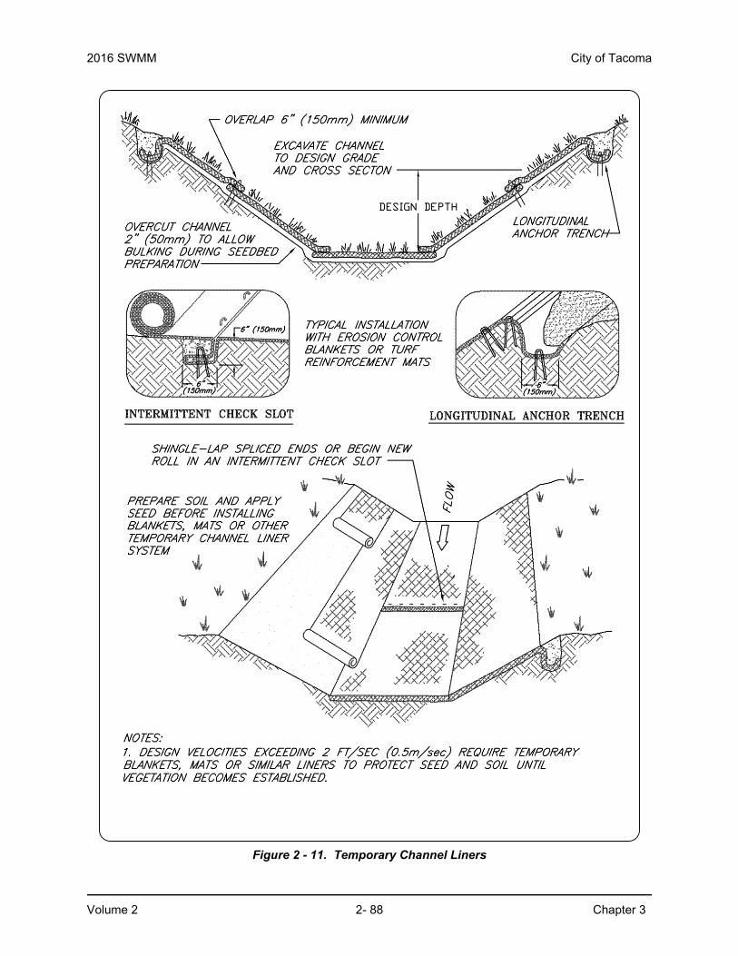
2016 SWMM City of Tacoma
Volume 2 2- 88 Chapter 3
Figure 2 - 11. Temporary Channel Liners

City of Tacoma 2016 SWMM
Chapter 3 2- 89 Volume 2
3.2.3 BMP C202: Channel Lining3.2.3.1 PurposeTo protect erodible channels by providing a channel liner using either blankets or riprap.
3.2.3.2 Conditions of Use• When natural soils or vegetated stabilized soils in a channel are not adequate to prevent
channel erosion.
• When a permanent ditch or pipe system is to be installed and a temporary measure is needed.
• In almost all cases, synthetic and organic coconut blankets are more effective than riprap for protecting channels from erosion. Blankets can be used with and without vegetation. Blanketed channels can be designed to handle any expected flow and longevity requirement. Some synthetic blankets have a predicted life span of 50 years or more, even in sunlight.
• The Federal Highway Administration recommends not using flexible liners whenever the slope exceeds 10 percent or the shear stress exceeds 8 pounds per square foot.
3.2.3.3 Design and Installation Specifications• See BMP C122 for information on blankets.
• Since riprap is used where erosion potential is high, construction must be sequenced so the riprap is put in place with the minimum possible delay (see Figure 2 - 12).
• Only disturb areas where riprap is to be placed if final preparation and placement of the riprap can immediately follow the initial disturbance. Where riprap is used for outlet protection, place the riprap before or in conjunction with the construction of the pipe or channel so it is in place when the pipe or channel begins to operate.
• The designer, after determining the appropriate riprap size for stabilization, shall consider that size to be a minimum size and then, based on riprap gradations actually available in the area, select the size or sizes that equal or exceed the minimum size. Consider the possibility of drainage structure damage by children when selecting a riprap size, especially if there is nearby water or a gully in which to toss the stones. See Volume 3, Section 3.4 for additional channel protection guidance.
• Use field stone or quarry stone of approximately rectangular shape for the riprap. The stone shall be hard and angular and of such quality that it will not disintegrate on exposure to water or weathering and shall be suitable in all respects for the purpose intended.
• Rubble concrete may be used, provided it has a density of at least 150 pounds per cubic foot and otherwise meets the requirement of this standard and specification.
• Place a lining of engineering filter fabric (geotextile) between the riprap and the underlying soil surface to prevent soil movement into or through the riprap. The geotextile should be keyed in at the top of the bank.
• Do not use filter fabric on slopes steeper than 1-1/2H:1V as slippage may occur. It should be used in conjunction with a layer of coarse aggregate (granular filter blanket) when the riprap to be placed is 12 inches and larger.
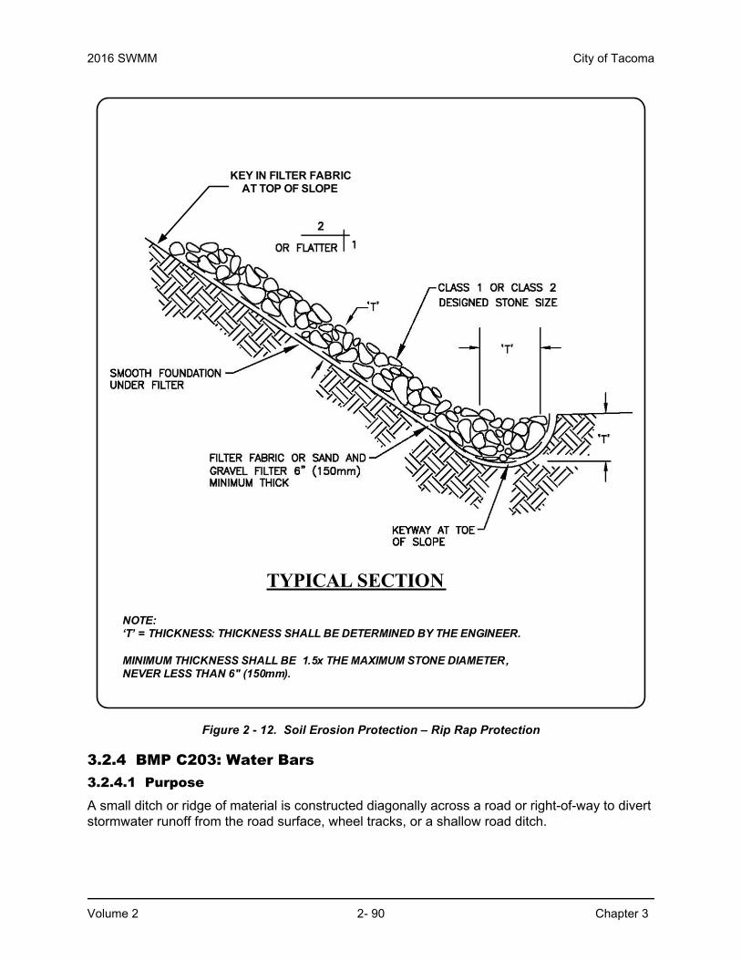
2016 SWMM City of Tacoma
Volume 2 2- 90 Chapter 3
Figure 2 - 12. Soil Erosion Protection – Rip Rap Protection
3.2.4 BMP C203: Water Bars 3.2.4.1 PurposeA small ditch or ridge of material is constructed diagonally across a road or right-of-way to divert stormwater runoff from the road surface, wheel tracks, or a shallow road ditch.
KEY IN FILTER FABRIC AT TOP OF SLOPE
TYPICAL SECTION
NOTE:‘T’ = THICKNESS: THICKNESS SHALL BE DETERMINED BY THE ENGINEER.
MINIMUM THICKNESS SHALL BE 1.5x THE MAXIMUM STONE DIAMETER,NEVER LESS THAN 6" (150mm).

City of Tacoma 2016 SWMM
Chapter 3 2- 91 Volume 2
3.2.4.2 Conditions of UseClearing right-of-way and construction of access for power lines, pipelines, and other similar installations often require long, narrow right-of-ways over sloping terrain. Disturbance and compaction promotes gully formation in these cleared strips by increasing the volume and velocity of runoff. Gully formation may be especially severe in tire tracks and ruts. To prevent gullying, runoff can often be diverted across the width of the right-of-way to undisturbed areas by using small predesigned diversions.
Give special consideration to each individual outlet area, as well as to the cumulative effect of added diversions. Use gravel to stabilize the diversion where significant vehicular traffic is anticipated.
3.2.4.3 Design and Installation Specifications• Height: 8-inch minimum measured from the channel bottom to the top of the ridge.
• Side slope of channel: 2H:1V maximum; 3H:1V or flatter when vehicles will cross.
• Base width of ridge: 6-inch minimum.
• Locate them to use natural drainage systems and to discharge into well vegetated stable areas.
• Guideline for Spacing:
• Grade of water bar and angle: Select angle that results in ditch slope of less than 2 percent.
• Install as soon as clearing and grading is complete. Reconstruct when construction is complete on a section when utilities are being installed.
• Compact the ridge when installed.
• Stabilize, seed, and mulch portions that are not subject to traffic. Gravel areas crossed by vehicles.
Slope % Spacing (ft)< 5 125
5 - 10 10010 - 20 7520 – 35 50
> 35 Use rock lined ditch
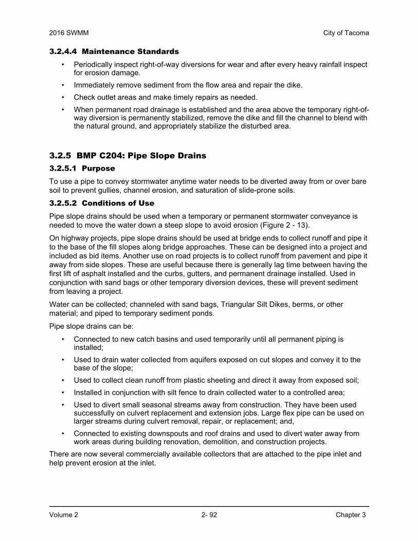
2016 SWMM City of Tacoma
Volume 2 2- 92 Chapter 3
3.2.4.4 Maintenance Standards • Periodically inspect right-of-way diversions for wear and after every heavy rainfall inspect
for erosion damage.
• Immediately remove sediment from the flow area and repair the dike.
• Check outlet areas and make timely repairs as needed.
• When permanent road drainage is established and the area above the temporary right-of-way diversion is permanently stabilized, remove the dike and fill the channel to blend with the natural ground, and appropriately stabilize the disturbed area.
3.2.5 BMP C204: Pipe Slope Drains3.2.5.1 PurposeTo use a pipe to convey stormwater anytime water needs to be diverted away from or over bare soil to prevent gullies, channel erosion, and saturation of slide-prone soils.
3.2.5.2 Conditions of UsePipe slope drains should be used when a temporary or permanent stormwater conveyance is needed to move the water down a steep slope to avoid erosion (Figure 2 - 13).
On highway projects, pipe slope drains should be used at bridge ends to collect runoff and pipe it to the base of the fill slopes along bridge approaches. These can be designed into a project and included as bid items. Another use on road projects is to collect runoff from pavement and pipe it away from side slopes. These are useful because there is generally lag time between having the first lift of asphalt installed and the curbs, gutters, and permanent drainage installed. Used in conjunction with sand bags or other temporary diversion devices, these will prevent sediment from leaving a project.
Water can be collected; channeled with sand bags, Triangular Silt Dikes, berms, or other material; and piped to temporary sediment ponds.
Pipe slope drains can be:
• Connected to new catch basins and used temporarily until all permanent piping is installed;
• Used to drain water collected from aquifers exposed on cut slopes and convey it to the base of the slope;
• Used to collect clean runoff from plastic sheeting and direct it away from exposed soil;
• Installed in conjunction with silt fence to drain collected water to a controlled area;
• Used to divert small seasonal streams away from construction. They have been used successfully on culvert replacement and extension jobs. Large flex pipe can be used on larger streams during culvert removal, repair, or replacement; and,
• Connected to existing downspouts and roof drains and used to divert water away from work areas during building renovation, demolition, and construction projects.
There are now several commercially available collectors that are attached to the pipe inlet and help prevent erosion at the inlet.

City of Tacoma 2016 SWMM
Chapter 3 2- 93 Volume 2
3.2.5.3 Design and Installation Specifications Size the pipe to convey the flow. The capacity for temporary drains shall be sufficient to handle the peak flow from a 10-year, 24-hour storm event assuming a Type 1A rainfall distribution (3.0-inches). Alternatively, use the 10-year return period flowrate, indicated by WWHM assuming a 15 minute timestep. Size permanent pipe slope drains using the guidance in Volume 3, Chapter 3.
• Use care in clearing vegetated slopes for installation.
• Re-establish cover immediately on areas disturbed by installation.
• Use temporary drains on new cut or fill slopes.
• Use diversion dikes or swales to collect water at the top of the slope.
• Ensure that the entrance area is stable and large enough to direct flow into the pipe.
• Piping of water through the berm at the entrance area is a common failure mode.
• The entrance shall consist of a standard flared end section for culverts 12 inches and larger with a minimum 6-inch metal toe plate to prevent runoff from undercutting the pipe inlet. The slope of the entrance shall be at least 3 percent. Sand bags may also be used at pipe entrances as a temporary measure.
• Thoroughly compact the soil around and under the pipe and entrance section to prevent undercutting.
• Securely connect the flared inlet section to the slope drain and have watertight connecting bands.
• Securely fasten, fuse or have gasketed, watertight fittings for the slope drain sections, and securely anchor them into the soil.
• Install thrust blocks anytime 90 degree bends are utilized. Depending on size of pipe and flow, these can be constructed with sand bags, straw bales staked in place, “T” posts and wire, or ecology blocks.
• Pipe needs to be secured along its full length to prevent movement. This can be done with steel “T” posts and wire. A post is installed on each side of the pipe and the pipe is wired to them. This should be done every 10-20 feet of pipe length, depending on the size of the pipe and quantity of water to be diverted.
• Use interceptor dikes to direct runoff into a slope drain. Ensure the height of the dike is at least 1 foot higher at all points than at the top of the inlet pipe.
• Stabilize the area below the outlet with a riprap apron (see BMP C209 Outlet Protection for the appropriate outlet material). For permanent installations, protect the outfall using guideance in Volume 3, Section 3.5.
• If the pipe slope drain is conveying sediment-laden water, direct all flows into the sediment trapping facility.
• Materials specifications for any permanent piped system shall conform to Volume 3, Chapter 3.
3.2.5.4 Maintenance Standards• Check inlet and outlet points regularly, especially after storms.
• The inlet should be free of undercutting, and no water should be going around the point of entry. If there are problems, the headwall should be reinforced with compacted earth or sand bags.

2016 SWMM City of Tacoma
Volume 2 2- 94 Chapter 3
• The outlet point should be free of erosion and installed with appropriate outlet protection.
• For permanent installations, inspect pipe periodically for vandalism and physical distress such as slides and wind-throw.
• Normally the pipe slope is so steep that clogging is not a problem with smooth wall pipe; however, debris may become lodged in the pipe.
Figure 2 - 13. Pipe Slope Drains
3.2.6 BMP C205: Subsurface Drains3.2.6.1 PurposeTo intercept, collect, and convey groundwater to a satisfactory outlet, using a perforated pipe or conduit below the ground surface. Subsurface drains are also known as “French drains.” The perforated pipe provides a dewatering mechanism to drain excessively wet soils, provide a stable base for construction, improve stability of structures with shallow foundations, or to reduce hydrostatic pressure to improve slope stability.
3.2.6.2 Conditions of UseUse when excessive water must be removed from the soil. The soil permeability, depth to water table, and impervious layers are all factors which may govern the use of subsurface drains.
3.2.6.3 Design and Installation Specifications• Relief drains

City of Tacoma 2016 SWMM
Chapter 3 2- 95 Volume 2
◦ Are used either to lower the water table in large, relatively flat areas, improve the growth of vegetation, or to remove surface water.
◦ Are installed along a slope and drain in the direction of the slope.
◦ Can be installed in a grid pattern, a herringbone pattern, or a random pattern.
• Interceptor drains
◦ Are used to remove excess groundwater from a slope, stabilize steep slopes, and lower the water table immediately below a slope to prevent the soil from becoming saturated.
◦ Are installed perpendicular to a slope and drain to the side of the slope.
◦ Usually consist of a single pipe or series of single pipes instead of a patterned layout.
• Depth and spacing considerations for interceptor drains
◦ The depth of an interceptor drain is determined primarily by the depth to which the water table is to be lowered or the depth to a confining layer. For practical reasons, the maximum depth is usually limited to 6 feet, with a minimum cover of 2 feet to protect the conduit.
◦ The soil should have depth and sufficient permeability to permit installation of an effective drainage system at a depth of 2 to 6 feet.
◦ An adequate outlet for the drainage system must be available either by gravity or pumping.
◦ The quantity and quality of discharge needs to be accounted for in the receiving stream (additional detention may be required).
◦ This standard does not apply to subsurface drains for building foundations or deep excavations.
• The capacity of an interceptor drain is determined by calculating the maximum rate of groundwater flow to be intercepted. Therefore, it is good practice to make complete subsurface investigations, including hydraulic conductivity of the soil, before designing a subsurface drainage system.

2016 SWMM City of Tacoma
Volume 2 2- 96 Chapter 3
• Drain sizing considerations
◦ Size subsurface drains to carry the required capacity without pressure flow. The minimum diameter for a subsurface drain is 4 inches.
◦ The minimum velocity required to prevent silting is 1.4 feet per second. Grade the line to achieve this velocity at a minimum. The maximum allowable velocity using a sand-gravel filter or envelope is 9 feet per second.
• Use filter material and fabric around all drains for proper bedding and filtration of fine materials. Envelopes and filters should surround the drain to a minimum of 3-inch thickness.
• Empty the outlet of the subsurface drain into a sediment pond or other appropriate sediment removal device. If free of sediment, it can empty into a receiving channel, swale, or stable vegetated area adequately protected from erosion and undermining.
• Construct the trench on a continuous grade with no reverse grades or low spots.
• Stabilize soft or yielding soils under the drain with gravel or other suitable material.
• Backfill immediately after placement of the pipe. Do not allow sections of pipe to remain uncovered overnight or during a rainstorm. Place backfill material in the trench in such a manner that the drain pipe is not displaced or damaged.
• Do not install permanent drains near trees as tree roots may clog the lines. Use solid pipe with watertight connections where necessary to pass a subsurface drainage system through a stand of trees.
• Outlet considerations
◦ Ensure that the outlet of a drain empties into a channel or other watercourse above the normal water level.
◦ Secure an animal guard to the outlet end of the pipe to keep out rodents.
◦ Use at least 10 feet of corrugated metal, cast iron, or heavy-duty plastic without perforations outlet pipe. Do not use an envelope or filter material around the outlet pipe, and bury at least two-thirds of the pipe length.
◦ When outlet velocities exceed those allowable for the receiving stream, provide outlet protection.
3.2.6.4 Maintenance Standards• Check the subsurface drains periodically to ensure that they are free-flowing and not
clogged with sediment or roots.
• Keep the outlet clean and free of debris.
• Keep surface inlets open and free of sediment and other debris.
• Trees located too close to a subsurface drain often clog the system with their roots. If a drain becomes clogged, relocate the drain or remove the trees as a last resort. Plan the placement of the drain to minimize this problem.
• Where drains are crossed by heavy vehicles, check the line to ensure that it is not crushed and use pipe material that can handle traffic loads.

City of Tacoma 2016 SWMM
Chapter 3 2- 97 Volume 2
3.2.7 BMP C206: Level Spreader3.2.7.1 PurposeTo provide a temporary outlet for dikes and diversions consisting of an excavated depression constructed at zero grade across a slope. To convert concentrated runoff to sheet flow and release it onto areas stabilized by existing vegetation or an engineered filter strip.
3.2.7.2 Conditions of Use• Used when a concentrated flow of water needs to be dispersed over a large area with
existing stable vegetation.
• Items to consider are:
◦ What is the risk of erosion or damage if the flow may become concentrated?
◦ Is an easement required if discharged to adjoining property?
◦ Most of the flow should be as groundwater and not as surface flow.
◦ Is there an unstable area downstream that cannot accept additional groundwater?
• Use only where the slopes are gentle, the water volume is relatively low, and the soil will adsorb most of the low flow events.
3.2.7.3 Design and Installation Specifications• Use above undisturbed areas that are stabilized by existing vegetation.
• If the level spreader has any low points, flow will concentrate, create channels and may cause erosion.
• Discharge area below the outlet must be uniform with a slope of less than 20%.
• Construct outlet level in a stable, undisturbed soil profile (not on fill).
• Do not allow the runoff to reconcentrate after release unless intercepted by another downstream measure.
• The grade of the channel for the last 20 feet of the dike or interceptor entering the level spreader shall be less than or equal to 1 percent. The grade of the level spreader shall be 0 percent to ensure uniform spreading of storm runoff.
• A 6-inch high gravel berm placed across the level lip shall consist of washed crushed rock, 2- to 4-inch or 3/4-inch to 1½-inch size.
• Calculate the spreader length by estimating the peak flow expected from the 10-year, 24-hour design storm event assuming a type 1A rainfall distribution (3.0-inches). The length of the spreader shall be a minimum of 15 feet for 0.1 cubic feet per second and shall be 10 feet for each 0.1 cubic feet per second there after to a maximum of 0.5 cubic feet per second per spreader. Use multiple spreaders for higher flows.
• The width of the spreader should be at least 6 feet.
• The depth of the spreader as measured from the lip should be at least 6 inches and it should be uniform across the entire length.
• Level spreaders shall be setback a minimum of 5 feet from the property line unless there is an easement for flow.
• Level spreaders, when installed every so often in grassy swales, keep the flows from concentrating. Materials that can be used include sand bags, lumber, logs, concrete, and pipe. To function properly, the material needs to be installed level and on contour.

2016 SWMM City of Tacoma
Volume 2 2- 98 Chapter 3
Figure 2 - 14 and Figure 2 - 15 provide a cross-section and a detail of a level spreader. A capped perforated pipe can also be used as a spreader.
3.2.7.4 Maintenance StandardsThe spreader should be inspected after every runoff event to ensure proper function.
• The contractor should avoid the placement of any material on the structure and should prevent construction traffic from crossing over the structure.
• If the spreader is damaged by construction traffic, immediately repair it.
Figure 2 - 14. Cross-Section of a Level Spreader
Figure 2 - 15. Detail of a Level Spreader

City of Tacoma 2016 SWMM
Chapter 3 2- 99 Volume 2
3.2.8 BMP C207: Check Dams3.2.8.1 PurposeConstruction of small dams across a swale or ditch reduces the velocity of concentrated flow and dissipates energy at the check dam.
3.2.8.2 Conditions of Use• Where temporary channels or permanent channels are not yet vegetated, channel lining
is infeasible, and velocity checks are required.
• Do not place check dams in streams unless approved by the State Department of Fish and Wildlife. Do not place check dams in wetlands without approval from the City of Tacoma Planning and Development Services and other appropriate state agencies.
• Do not place check dams below the expected backwater from any salmonid bearing water between September 15 and June 15 to ensure that there is no loss of high flow refuge habitat for overwintering juvenile salmonids and emergent salmonid fry.
3.2.8.3 Design and Installation Specifications• Construct rock check dams from appropriately sized rock; rock or pea-gravel filled bags;
or other products intended for this purpose. The rock used must be large enough to stay in place given the expected design flow through the channel. The rock must be placed by hand or by mechanical means (no dumping of rock to form dam) to achieve complete coverage of the ditch or swale and to ensure that the center of the dam is lower than the edges.
• Before installing check dams bypass upstream flow away from the work area.
• Whatever material is used, the dam should form a triangle when viewed from the side. This prevents undercutting as water flows over the face of the dam rather than falling directly onto the ditch bottom.
• Check dams in association with sumps work more effectively at slowing flow and retaining sediment than just a check dam alone. A deep sump should be provided immediately upstream of the check dam.
• In some cases, if carefully located and designed, check dams can remain as permanent installations with very minor regrading. They may be left as either spillways, in which case accumulated sediment would be graded and seeded, or as check dams to prevent further sediment from leaving the site.
• Check dams can be constructed of either rock or pea-gravel filled bags. Numerous new products are also available for this purpose. They tend to be re-usable, quick and easy to install, effective, and cost efficient.
• Check dams should be placed perpendicular to the flow of water.
• The maximum spacing between the dams shall be such that the toe of the upstream dam is at the same elevation as the top of the downstream dam.
• Keep a maximum height of 2 feet at the center of the dam.
• Keep the center of the check dam at least 12 inches lower than the outer edges at natural ground elevation.
• Keep the side slopes of the check dam at 2H:1V or flatter.
• Key the stone into the ditch banks and extend it beyond the abutments a minimum of 18 inches to avoid washouts from overflow around the dam.

2016 SWMM City of Tacoma
Volume 2 2- 100 Chapter 3
• Use filter fabric foundation under a rock or sand bag check dam. If a blanket ditch liner is used, this is not necessary. A piece of organic or synthetic blanket cut to fit will also work for this purpose.
• In the case of grass-lined ditches and swales, remove all check dams and accumulated sediment when the grass has matured sufficiently to protect the ditch or swale - unless the slope of the swale is greater than 4 percent. Seed and mulch the area beneath the check dams immediately after dam removal.
• Ensure that channel appurtenances, such as culvert entrances below check dams, are not subject to damage or blockage from displaced stones. Figure 2 - 16 depicts a typical rock check dam.
3.2.8.4 Maintenance Standards• Monitor check dams for performance and sediment accumulation during and after each
runoff producing rainfall. Remove sediment when it reaches one half the sump depth.
• Anticipate submergence and deposition above the check dam and erosion from high flows around the edges of the dam.
• If significant erosion occurs between dams, install a protective riprap liner in that portion of the channel.

City of Tacoma 2016 SWMM
Chapter 3 2- 101 Volume 2
Figure 2 - 16. Check Dams

2016 SWMM City of Tacoma
Volume 2 2- 102 Chapter 3
3.2.9 BMP C208: Triangular Silt Dike (Geotextile-Encased Check Dam)3.2.9.1 PurposeTriangular silt dikes (TSDs) may be used as check dams, for perimeter protection, for temporary soil stockpile protection, for drop inlet protection, or as a temporary interceptor dike (refer to Figure 2 - 17).
3.2.9.2 Conditions of Use• May be used on soil or pavement with adhesive or staples.
• TSDs have been used to build temporary:
◦ sediment ponds◦ diversion ditches◦ concrete wash out facilities◦ curbing◦ water bars◦ level spreaders◦ berms
3.2.9.3 Design and Installation Specifications• Made of urethane foam sewn into a woven geosynthetic fabric.
• It is triangular, 10 inches to 14 inches high in the center, with a 20-inch to 28-inch base. A 2–foot apron extends beyond both sides of the triangle along its standard section of 7 feet. A sleeve at one end allows attachment of additional sections as needed.
• Install with ends curved up to prevent water from flowing around the ends.
• The fabric flaps and check dam units are attached to the ground with wire staples. Wire staples should be No. 11 gauge wire and should be 200 mm to 300 mm in length.
• When multiple units are installed, the sleeve of fabric at the end of the unit shall overlap the abutting unit and be stapled.
• Check dams should be located and installed as soon as construction will allow.
• Check dams should be placed perpendicular to the flow of water.
• When used as check dams, the leading edge must be secured with rocks, sandbags, or a small key slot and staples.
3.2.9.4 Maintenance Standards• Monitor triangular silt dikes for performance and sediment accumulation during and after
each runoff producing rainfall. Remove sediment when it reaches one half the height of the dam.
• Anticipate submergence and deposition above the triangular silt dam and erosion from high flows around the edges of the dam. Immediately repair any damage or undercutting of the dam.
• In the case of grass-lined ditches and swales, remove check dams and accumulated sediment when the grass has matured sufficiently to protect the ditch or swale, unless the slope of the swale is greater than 4 percent. Seed and mulch the area beneath the check dams immediately after dam removal.

City of Tacoma 2016 SWMM
Chapter 3 2- 103 Volume 2
Figure 2 - 17. Sediment Barrier – Geosynthetic Dike

2016 SWMM City of Tacoma
Volume 2 2- 104 Chapter 3
3.2.10 BMP C209: Outlet Protection3.2.10.1 PurposeOutlet protection prevents scour at conveyance outlets and minimizes the potential for downstream erosion by reducing the velocity of concentrated stormwater flows.
3.2.10.2 Conditions of UseOutlet protection is required at the outlets of all ponds, pipes, ditches, or other conveyances, and where runoff is conveyed to a natural or manmade drainage feature such as a stream, wetland, lake, or ditch.
3.2.10.3 Design and Installation Specifications• Protect the receiving channel at the outlet of a culvert from erosion by rock lining a
minimum of 6 feet downstream and extending rock lining up the channel sides a minimum of 1–foot above the maximum tailwater elevation or 1-foot above the crown, whichever is higher. For large pipes (more than 18 inches in diameter), the outlet protection lining of the channel is lengthened to four times the diameter of the culvert.
• See Volume 3, Section 3.5 for permanent outlet protection.
• Organic or synthetic erosion blankets, with or without vegetation, may be, cheaper, and easier to install than rock. Materials can be chosen using manufacturer product specifications. ASTM test results are available for most products and the designer can choose the correct material for the expected flow.
• With low flows, vegetation (including sod) can be effective.
• Use the following guidelines for riprap outlet protection:
◦ If the discharge velocity at the outlet is less than 5 feet per second (pipe slope less than 1 percent), use 2-inch to 8-inch riprap. Minimum thickness is 1-foot.
◦ For 5 to 10 feet per second discharge velocity at the outlet (pipe slope less than 3 percent), use 24-inch to 4-foot riprap. Minimum thickness is 2 feet.
◦ For outlets at the base of steep slope pipes (pipe slope greater than 10 percent), an engineered energy dissipater shall be used.
• Always use filter fabric or erosion control blankets under riprap to prevent scour and channel erosion.
• New pipe outfalls can provide an opportunity for low-cost fish habitat improvements. For example, an alcove of low-velocity water can be created by constructing the pipe outfall and associated energy dissipater back from the stream edge and digging a channel, over-widened to the upstream side, from the outfall. Overwintering juvenile and migrating adult salmonids may use the alcove as shelter during high flows. Bank stabilization, bioengineering, and habitat features may be required for disturbed areas. See Volume 3 for more information on outfall system design.
3.2.10.4 Maintenance Standards• Inspect and repair as needed.
• Add rock as needed to maintain the intended function.
• Clean energy dissipater if sediment builds up.
City of Tacoma 2016 SWMM
Chapter 3 2- 105 Volume 2
3.2.11 BMP C220: Storm Drain Inlet Protection3.2.11.1 PurposeTo prevent coarse sediment from entering drainage systems prior to permanent stabilization of the disturbed area.
3.2.11.2 Conditions of Use• Where storm drain inlets are to be made operational before permanent stabilization of the
disturbed drainage area.
• Provide protection for all storm drain inlets downslope and within 500 feet of a disturbed or construction area, unless the runoff that enters the catch basin will be conveyed to a sediment pond or trap. Inlet protection may be used anywhere to protect the drainage system. It is likely that the drainage system will still require cleaning.
• Table 2 - 11 lists several options for inlet protection. All of the methods for storm drain inlet protection are prone to plugging and require a high frequency of maintenance. Drainage areas should be limited to 1 acre or less. Emergency overflows may be required where stormwater ponding would cause a hazard. If an emergency overflow is provided, additional end-of-pipe treatment may be required.
• Only bag filter type catch basin filters (per Section 3.2.11.3) are allowed within the right of way.
3.2.11.3 Design and Installation Specifications
Excavated Drop Inlet Protection
• An excavated impoundment around the storm drain. Sediment settles out of the stormwater prior to entering the storm drain.
Table 2 - 11: Storm Drain Inlet Protection
Type of Inlet ProtectionEmergency
Overflow
Applicable for Paved/Earthen
SurfacesConditions of Use
Excavated drop inlet protection
Yes, temporary flooding will occur
EarthenApplicable for heavy flows. Easy to maintain. Large area requirement:30’ x 30’ per acre.
Block and gravel drop filter
Yes Paved or earthenApplicable for heavy concentrated flows. Will not pond.
Gravel and mesh filter No PavedApplicable for heavy concentrated flows. Will pond. Can withstand traffic.
Catch basin filters Yes Paved or earthen Frequent maintenance required.
Curb inlet protection with a wooden weir
Small capacity overflow
PavedUsed for sturdy, more compact installation.
Block and gravel curb inlet protection
Yes Earthen Sturdy, but limited filtration.
Culvert inlet sediment trap
18-month expected life.

2016 SWMM City of Tacoma
Volume 2 2- 106 Chapter 3
• Provide depth of 1 to 2 feet, as measured from the crest of the inlet structure.
• Slope sides of excavation no steeper than 2H:1V.
• Minimum volume of excavation 35 cubic yards.
• Shape basin to fit site with longest dimension oriented toward the longest inflow area.
• Install provisions for draining to prevent standing water problems.
• Clear the area of all debris.
• Grade the approach to the inlet uniformly.
• Drill weep holes into the side of the inlet.
• Protect weep holes with screen wire and washed aggregate.
• Seal weep holes when removing structure and stabilizing area.
• It may be necessary to build a temporary dike to the down slope side of the structure to prevent bypass flow.
Block and Gravel Filter
• A barrier formed around the storm drain inlet with standard concrete blocks and gravel. See Figure 2 - 18.
• Provide a height 1 to 2 feet above inlet.
• Recess the first row 2 inches into the ground for stability.
• Support subsequent courses by placing a piece of 2x4 lumber through the block opening.
• Do not use mortar.
• Lay some blocks in the bottom row on their side for dewatering the pool.
• Place hardware cloth or comparable wire mesh with ½-inch openings over all block openings.
• Place gravel just below the top of blocks on slopes of 2H:1V or flatter.
• An alternative design is a gravel donut.
• Provide an inlet slope of 3H:1V.
• Provide an outlet slope of 2H:1V.
• Provide a 1-foot wide level stone area between the structure and the inlet.
• Use inlet slope stones 3 inches in diameter or larger.
• For outlet slope use gravel ½- to ¾-inch at a minimum thickness of 1-foot.
Gravel and Wire Mesh Filter
• A gravel barrier placed over the top of the inlet (see Figure 2 - 19). This structure does not provide an overflow.
• Use hardware cloth or comparable wire mesh with ½-inch openings.
• Use coarse aggregate.
• Place wire mesh over the drop inlet so that the wire extends a minimum of 1-foot beyond each side of the inlet structure.
• If more than one strip of mesh is necessary, overlap the strips.

City of Tacoma 2016 SWMM
Chapter 3 2- 107 Volume 2
• Place coarse aggregate over the wire mesh.
• The depth of the gravel should be at least 12 inches over the entire inlet opening and extend at least 18 inches on all sides.
Catchbasin Filters
• Inserts (Figure 2 - 20) shall be designed by the manufacturer for use at construction sites. The limited sediment storage capacity increases the frequency of inspection and maintenance required, which may be daily for heavy sediment loads. The maintenance requirements can be reduced by combining a catchbasin filter with another type of inlet protection. This type of inlet protection provides flow bypass without overflow and therefore may be a better method for inlets located along active rights-of-way.
• Provide a minimum of 5 cubic feet of storage.
• Requires dewatering provisions.
• Provide a high-flow bypass that will not clog under normal use at a construction site.
• The catchbasin filter is inserted in the catchbasin just below the grating.
• Only bag filter type catch basin filters are allowed in the City right-of-way.

2016 SWMM City of Tacoma
Volume 2 2- 108 Chapter 3
Figure 2 - 18. Drop Inlet with Block and Gravel Filter

City of Tacoma 2016 SWMM
Chapter 3 2- 109 Volume 2
Figure 2 - 19. Gravel and Wire Mesh Filter

2016 SWMM City of Tacoma
Volume 2 2- 110 Chapter 3
Figure 2 - 20. Catchbasin Filter

City of Tacoma 2016 SWMM
Chapter 3 2- 111 Volume 2
Curb Inlet Protection with Wooden Weir
Barrier formed around a curb inlet with a wooden frame and gravel.
• Use wire mesh with ½-inch openings.
• Use extra strength filter cloth.
• Construct a frame.
• Attach the wire and filter fabric to the frame.
• Pile coarse washed aggregate against the wire and fabric.
• Place weight on frame anchors.
Block and Gravel Curb Inlet Protection
Barrier formed around an inlet with concrete blocks and gravel. See Figure 2 - 21.
• Use wire mesh with ½-inch openings.
• Place two concrete blocks on their sides abutting the curb at either side of the inlet opening. These are spacer blocks.
• Place a 2x4 stud through the outer holes of each spacer block to align the front blocks.
• Place blocks on their sides across the front of the inlet and abutting the spacer blocks.
• Place wire mesh over the outside vertical face.
• Pile coarse aggregate against the wire to the top of the barrier.

2016 SWMM City of Tacoma
Volume 2 2- 112 Chapter 3
Figure 2 - 21. Block and Gravel Curb Inlet Protection
PLAN VIEW
BACK OF SIDEWALK CATCH BASIN
BACK OF CURB
2X4 WOOD STUD
CONCRETE BLOCKCURB INLET
WIRE SCREEN OR FILTER FABRIC CONCRETE BLOCK
CONCRETE BLOCK
CURB INLET
3/4” DRAIN GRAVEL (20 mm)
3/4” DRAIN GRAVEL (20 mm)
SECTION A – A
A
A
PONDING HEIGHT
OVERFLOW
CATCH BASIN
WIRE SCREEN OR FILTER FABRIC
2X4 WOOD STUD (100x50 TIMBER STUD)
NOTE:1. USE BLOCK AND GRAVEL TYPE SEDIMENT BARRIER WHEN CURB INLET IS LOCATED IN GENTLY SLOPING STREET SEGMENT, WHERE WATER CAN POND AND ALLOW SEDIMENT TO SEPARATE FROM RUNOFF.2. BARRIER SHALL ALLOW FOR OVERFLOW FROM SEVERE STORM EVENT.3. INSPECT BARRIERS AND REMOVE SEDIMENT AFTER EACH STORM EVENT. SEDIMENT AND GRAVEL MUST BE REMOVED FROM THE TRAVELED WAY IMMEDIATELY .
City of Tacoma 2016 SWMM
Chapter 3 2- 113 Volume 2
Curb and Gutter Sediment Barrier
Sandbag or rock berm (riprap and aggregate) 3 feet high and 3 feet wide in a horseshoe shape. See Figure 2 - 22.
• Construct a horseshoe shaped berm, faced with coarse aggregate if using riprap, 3 feet high and 3 feet wide, at least 2 feet from the inlet.
• Construct a horseshoe shaped sedimentation trap on the outside of the berm sized to sediment trap standards for protecting a culvert inlet.
• Sandbag must be gravel filled.
3.2.11.4 Maintenance Standards• Inspect catch basin filters frequently, especially after storm events. If the insert becomes
clogged, clean or replace it.
• For systems using stone filters: If the stone filter becomes clogged with sediment, the stones must be pulled away from the inlet and cleaned or replaced. Since cleaning of gravel at a construction site may be difficult, an alternative approach would be to use the clogged stone as fill and put fresh stone around the inlet.
• Do not wash sediment into storm drains while cleaning. Spread all excavated material evenly over the surrounding land area or stockpile and stabilize as appropriate.
• Do not allow accumulated sediment to enter the storm drain system.
• Inlet protection shall be removed when area is fully stabilized and erosion and sediment controls are no longer needed.

2016 SWMM City of Tacoma
Volume 2 2- 114 Chapter 3
Figure 2 - 22. Curb and Gutter Sediment Barrier

City of Tacoma 2016 SWMM
Chapter 3 2- 115 Volume 2
3.2.12 BMP C231: Brush Barrier3.2.12.1 PurposeThe purpose of brush barriers is to reduce the transport of coarse sediment from a construction site by providing a temporary physical barrier to sediment and reducing the runoff velocities of overland flow.
3.2.12.2 Conditions of Use• Brush barriers may be used downslope of all disturbed areas of less than one-quarter
acre.
• Brush barriers are not intended to treat concentrated flows, nor are they intended to treat substantial amounts of overland flow. Any concentrated flows must be conveyed through the drainage system to a sediment pond. The only circumstance in which overland flow can be treated solely by a barrier, rather than by a sediment pond, is when the area draining to the barrier is small.
• Only install brush barriers on contours.
3.2.12.3 Design and Installation Specifications• Height 2 feet (minimum) to 5 feet (maximum).
• Width 5 feet at base (minimum) to 15 feet (maximum).
• Filter fabric (geotextile) may be anchored over the brush berm to enhance the filtration ability of the barrier. Ten-ounce burlap is an adequate alternative to filter fabric.
• Chipped site vegetation, compost, or wood-based mulch (hog fuel) as specified in BMP C121: Mulching can be used to construct brush barriers.
• A 100 percent biodegradable installation can be constructed using 10-ounce burlap held in place by wooden stakes. Figure 2 - 23 depicts a typical brush barrier.
3.2.12.4 Maintenance Standards• Do not allow erosion or concentrated runoff under or around the barrier. If concentrated
flows are bypassing the barrier, it must be expanded or augmented by toed-in filter fabric.
• Maintain the dimensions of the barrier.

2016 SWMM City of Tacoma
Volume 2 2- 116 Chapter 3
Figure 2 - 23. Brush Barrier
3.2.13 BMP C232: Gravel Filter Berm3.2.13.1 PurposeA gravel filter berm is constructed on rights-of-way or traffic areas within a construction site to retain sediment by using a filter berm of gravel or crushed rock.
3.2.13.2 Conditions of UseWhere a temporary measure is needed to retain sediment from rights-of-way or in traffic areas on construction sites.
3.2.13.3 Design and Installation Specifications• Berm material shall be ¾ to 3 inches in size, washed well-graded gravel or crushed rock,
with less than 5 percent fines.
• Space berms:
◦ Every 300 feet on slopes less than 5 percent
◦ Every 200 feet on slopes between 5 percent and 10 percent
City of Tacoma 2016 SWMM
Chapter 3 2- 117 Volume 2
◦ Every 100 feet on slopes greater than 10 percent
• Berm dimensions:
◦ 1 foot high with 3:1 side slopes
◦ 8 linear feet per 1 cubic foot per second runoff based on the 10-year, 24-hour design storm event assuming a Type 1A rainfall distribution (3.0-inches)
3.2.13.4 Maintenance StandardsRegular inspection is required. Remove sediment and replace filter material as needed.
3.2.14 BMP C233: Silt Fence3.2.14.1 PurposeUse of a silt fence reduces the transport of coarse sediment from a construction site by providing a temporary physical barrier to sediment and reducing the runoff velocities of overland flow. See Figure 2 - 24 for details on silt fence construction.
3.2.14.2 Conditions of Use• Silt fence may be used downslope of all disturbed areas.
• Silt fence shall prevent soil carried by runoff water from going beneath, through, or over the top of the silt fence, but shall allow the water to pass through the fence.
• Silt fence is not intended to treat concentrated flows, nor is it intended to treat substantial amounts of overland flow. Convey any concentrated flows through the drainage system to a sediment pond. The only circumstance in which overland flow can be treated solely by a silt fence is when the area draining to the fence is one acre or less and flow rates are less than 0.5 cfs.
• Do not construct silt fences in streams or use them in V-shaped ditches. They are not an adequate method of silt control for anything deeper than sheet or overland flow.
3.2.14.3 Design and Installation Specifications• Drainage area of 1 acre or less or in combination with appropriate sediment removal
BMPs on larger sites.
• Maximum slope steepness (perpendicular to fence line) 1H:1V.
• Maximum sheet or overland flowpath length to the fence of 100 feet.
• No flows greater than 0.5 cubic feet per second.

2016 SWMM City of Tacoma
Volume 2 2- 118 Chapter 3
• The geotextile used shall meet the following standards. All geotextile properties listed below are minimum average roll values (i.e., the test result for any sampled roll in a lot shall meet or exceed the values shown in Table 2 - 12).
• Support standard strength fabrics with wire mesh, chicken wire, 2-inch x 2-inch wire, safety fence, or jute mesh to increase the strength of the fabric. Silt fence materials are available that have synthetic mesh backing attached.
• Silt fence material shall contain ultraviolet ray inhibitors and stabilizers to provide a minimum of six months of expected usable construction life at a temperature range of 0° to 120° Fahrenheit.
• 100 percent biodegradable silt fence is available that is strong and long lasting.
• The following are standard design and installation methods. Refer to Figure 2 - 24 for standard silt fence details.
◦ Install and maintain temporary silt fences at the locations shown in the plans. Install the silt fences in the areas of clearing, grading, or drainage prior to starting those activities. Do not consider a silt fence temporary if the silt fence must function beyond the life of the contract. The silt fence shall prevent soil carried by runoff water from going beneath, through, or over the top of the silt fence, but shall allow the water to pass through the fence.
◦ The minimum height of the top of silt fence shall be 2 feet and the maximum height shall be 2½ feet above the original ground surface.
◦ Sew the silt fence fabric together at the point of manufacture, or at an approved location as determined by the Engineer, to form lengths as required. Locate all sewn seams at a support post. Alternatively, two sections of silt fence can be overlapped, provided the Contractor can demonstrate, to the satisfaction of the Engineer, that the overlap is long enough and adjacent fence sections are close enough together to prevent silt laden water from escaping through the fence at the overlap.
◦ Attach the silt fence fabric on the up-slope side of the posts and support system with staples, wire, or in accordance with the manufacturer's recommendations. Attach the silt fence fabric to the posts in a manner that reduces the potential for geotextile tearing at the staples, wire, or other connection device. Silt fence back-up support for the fabric in the form of a wire or plastic mesh is dependent on the properties of the fabric selected for use. If wire or plastic back-up mesh is used, fasten the mesh
Table 2 - 12: Geotextile Standards
Standard Description
Polymeric Mesh AOS (ASTM D4751)
0.60 mm maximum for silt film wovens (#30 sieve). 0.30 mm maximum for all other geotextile types (#50 sieve). 0.15 mm minimum for all fabric types (#100 sieve).
Water Permittivity (ASTM D4491) 0.02 sec-1 minimum
Grab Tensile Strength (ASTM D4632)180 lbs. minimum for extra strength fabric.
100 lbs. minimum for standard strength fabric.
Grab Tensile Strength (ASTM D4632) 30% maximum
Ultraviolet Resistance (ASTM D4355) 70% minimum

City of Tacoma 2016 SWMM
Chapter 3 2- 119 Volume 2
securely to the up-slope of the posts with the fabric being up-slope of the mesh back-up support.
◦ Bury the fabric at the bottom of the fence in a trench to a minimum depth of 4 inches below the ground surface. Backfill the trench and tamp the soil in place over the buried portion of the fabric, such that no flow can pass beneath the fence and scouring can not occur. When wire or polymeric back-up support mesh is used, the wire or polymeric mesh shall extend into the trench a minimum of 3 inches.
◦ Drive fence posts in to a minimum depth of 18 inches. A minimum depth of 12 inches is allowed if topsoil or other soft subgrade soil is not present and a minimum depth of 18 inches cannot be reached. Increase fence post depths by 6 inches if the fence is located on slopes of 3H:1V or steeper and the slope is perpendicular to the fence. If required post depths cannot be obtained, adequately secure the posts by bracing or guying to prevent overturning of the fence due to sediment loading.
◦ Locate the silt fences on contour as much as possible, except at the ends of the fence, where the fence shall be turned uphill such that the silt fence captures the runoff water and prevents water from flowing around the end of the fence.
◦ If the fence must cross contours, with the exception of the ends of the fence, place gravel check dams perpendicular to the back of the fence to minimize concentrated flow and erosion along the back of the fence. The gravel check dams shall be approximately 1-foot deep at the back of the fence and be perpendicular to the fence at the same elevation until the top of the check dam intercepts the ground surface behind the fence. The gravel check dams shall consist of crushed surfacing base course, gravel backfill for walls, or shoulder ballast. Locate the gravel check dams every 10 feet along the fence where the fence must cross contours. The slope of the fence line where contours must be crossed shall not be steeper than 3H:1V.
◦ Use wood, steel or equivalent posts. Wood posts shall have minimum dimensions of 2 inches by 2 inches, minimum by 3 feet minimum length, and shall be free of defects such as knots, splits, or gouges. Steel posts shall consist of either size No. 6 rebar or larger; ASTM A120 steel pipe with a minimum diameter of 1-inch; U, T, L, or C shape steel posts with a minimum weight of 1.35 pounds per foot; or other steel posts having equivalent strength and bending resistance to the post sizes listed. The spacing of the support posts shall be a maximum of 6 feet.
◦ Fence back-up support, if used, shall consist of steel wire with a maximum mesh spacing of 2 inches, or a prefabricated polymeric mesh. The strength of the wire or polymeric mesh shall be equivalent to or greater than 180 pounds grab tensile strength. The polymeric mesh must be as resistant to ultraviolet radiation as the geotextile it supports.
• Specification details for silt fence installation using the slicing method follow. Refer to Figure 2 - 25 for slicing method details.
◦ The base of both end posts must be at least 2 to 4 inches above the top of the silt fence fabric on the middle posts for ditch checks to drain properly. Use a hand level or string level, if necessary, to mark base points before installation.
◦ Install posts 3 to 4 feet apart in critical retention areas and a maximum of 6 feet apart in standard applications. If wire backing is used, post spacing may be increased to 8-foot maximum.

2016 SWMM City of Tacoma
Volume 2 2- 120 Chapter 3
◦ Install posts 24 inches deep on the downstream side of the silt fence, and as close as possible to the fabric, enabling posts to support the fabric from upstream water pressure.
◦ Install posts with the nipples facing away from the silt fence fabric.
◦ Attach the fabric to each post with three ties, all spaced within the top 8 inches of the fabric. Attach each tie diagonally 45 degrees through the fabric, with each puncture at least 1 inch vertically apart. In addition, each tie should be positioned to hang on a post nipple when tightening to prevent sagging.
◦ Wrap approximately 6 inches of fabric around the end posts and secure with 3 ties.
◦ No more than 24 inches of a 36-inch fabric is allowed above ground level.
◦ The installation should be checked and corrected for any deviation before compaction. Use a flat-bladed shovel to tuck fabric deeper into the ground, if necessary.
◦ Compaction is vitally important for effective results. Compact the soil immediately next to the silt fence fabric with the front wheel of a tractor, skid steer, or roller exerting at least 60 pounds per square inch. Compact the upstream side first and then each side twice for a total of four trips.

City of Tacoma 2016 SWMM
Chapter 3 2- 121 Volume 2
3.2.14.4 Maintenance Standards• Repair any damage immediately.
• If concentrated flows are evident uphill of the fence, intercept and convey them to a sediment pond.
• It is important to check the uphill side of the fence for signs of the fence clogging, acting as a barrier to flow, and then causing channelization of flows parallel to the fence. If this occurs, replace the fence or remove the trapped sediment.
• Remove sediment deposits when the deposit reaches approximately one-third the height of the silt fence, or install a second silt fence.
• If the filter fabric (geotextile) has deteriorated due to ultraviolet breakdown, replace it.

2016 SWMM City of Tacoma
Volume 2 2- 122 Chapter 3
Figure 2 - 24. Silt Fence
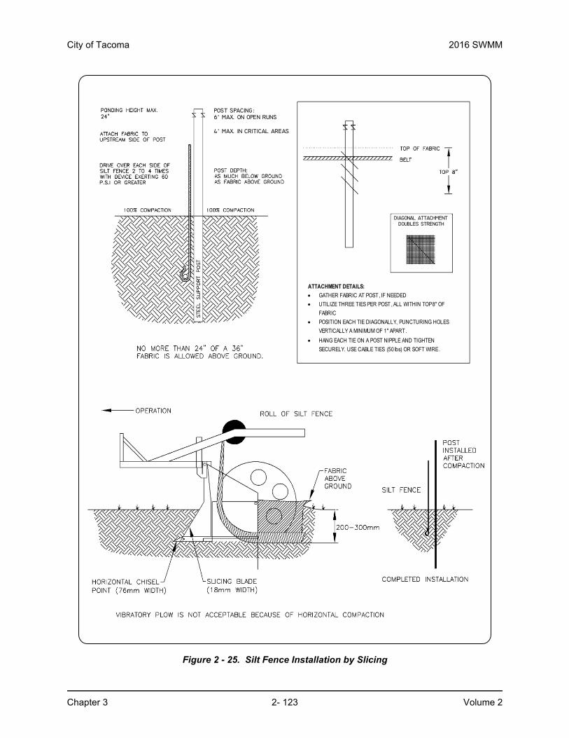
City of Tacoma 2016 SWMM
Chapter 3 2- 123 Volume 2
Figure 2 - 25. Silt Fence Installation by Slicing
ATTACHMENT DETAILS:
GATHER FABRIC AT POST , IF NEEDED
UTILIZE THREE TIES PER POST , ALL WITHIN TOP 8" OF
FABRIC
POSITION EACH TIE DIAGONALLY, PUNCTURING HOLES
VERTICALLY A MINIMUM OF 1" APART .
HANG EACH TIE ON A POST NIPPLE AND TIGHTEN
SECURELY. USE CABLE TIES (50 lbs) OR SOFT WIRE.
POST SPACING:6’ MAX. ON OPEN RUNS
4’ MAX. IN CRITICAL AREAS
DIAGONAL ATTACHMENTDOUBLES STRENGTH

2016 SWMM City of Tacoma
Volume 2 2- 124 Chapter 3
3.2.15 BMP C234: Vegetated Strip3.2.15.1 PurposeVegetated strips reduce the transport of coarse sediment from a construction site by providing a temporary physical barrier to sediment and reducing the runoff velocities of overland flow.
3.2.15.2 Conditions of UseVegetated strips may be used downslope of all disturbed areas.
Vegetated strips are not intended to treat concentrated flows, nor are they intended to treat substantial amounts of overland flow. Convey any concentrated flows through the drainage system to a sediment pond. The only circumstance in which overland flow can be treated solely by a strip, rather than by a sediment pond, is when the criteria shown in Table 2 - 13 are met.
3.2.15.3 Design and Installation Specifications• The vegetated strip shall consist of a minimum of a 25-foot wide continuous strip of dense
vegetation with permeable topsoil. Grass-covered, landscaped areas are generally not adequate because the volume of sediment overwhelms the grass. Ideally, vegetated strips shall consist of undisturbed native growth with a well-developed soil that allows for infiltration of runoff.
• The slope within the strip shall not exceed 4H:1V.
• Delineate the uphill boundary of the vegetated strip with clearing limits.
3.2.15.4 Maintenance Standards• Seed any areas damaged by erosion or construction activity immediately and protect with
mulch.
• If more than 5 feet of the original vegetated strip width has had vegetation removed or is being eroded, install sod.
• If there are indications that concentrated flows are traveling across the vegetated strip, surface water controls must be installed to reduce the flows entering the vegetated strip, or install additional perimeter protection.
3.2.16 BMP C235: Wattles3.2.16.1 PurposeWattles are temporary erosion and sediment control barriers consisting of straw, compost or other material that is wrapped in biodegradable tubular plastic or similar encasing material. They
Table 2 - 13: Vegetated Strips
Average Slope Slope Percent Flowpath Length
1.5H:1V or less 67% or less 100 feet
2H:1V or less 50% or less 115 feet
4H:1V or less 25% or less 150 feet
6H:1V or less 16.7% or less 200 feet
10H:1V or less 10% or less 250 feet

City of Tacoma 2016 SWMM
Chapter 3 2- 125 Volume 2
reduce the velocity and can spread the flow of rill and sheet runoff, and can capture and retain sediment. Wattles are typically 8 to 10 inches in diameter and 25 to 30 feet in length. The wattles are placed in shallow trenches and staked along the contour of disturbed or newly constructed slopes. See Figure 2 - 26 for typical construction details.
3.2.16.2 Conditions of Use• Use wattles
◦ In disturbed areas that require immediate erosion protection.
◦ On exposed soils during the period of short construction delays.
◦ On slopes requiring stabilization until permanent vegetation can be established.
• Wattles are typically effective for one to two seasons.
• If conditions are appropriate, wattles can be staked to the ground using live cuttings for added revegetation.
3.2.16.3 Design Criteria• It is critical that wattles are installed perpendicular to the flow direction and parallel to the
slope contour.
• Dig narrow trenches across the slope on contour to a depth of 3 to 5 inches on clay soils and soils with gradual slopes. On loose soils, steep slopes, and areas with high rainfall, dig the trenches to a depth of 5 to 7 inches, or 1/2 to 2/3 of the thickness of the wattle.
• Start building trenches and installing wattles from the base of the slope and work up. Excavated material should be spread evenly along the uphill slope and compacted using hand tamping or other methods.
• Construct trenches at contour intervals of 3 to 30 feet apart depending on the steepness of the slope, soil type, and rainfall. The steeper the slope, the closer together the trenches shall be.
• Install the wattles snugly into the trenches and abut tightly end to end. Do not overlap the ends. Rilling can occur beneath wattles if not properly entrenched, and water can pass between wattles if not tightly abutted.
• Install stakes at each end of the wattle, and at 4-foot centers along entire length of wattle.
• If required, install pilot holes for the stakes using a straight bar to drive holes through the wattle and into the soil.
• At a minimum, wooden stakes should be approximately 3/4 x 3/4 x 24 inches, minimum. Live cuttings or 3/8-inch rebar can also be used for stakes.
• Stakes should be driven through the middle of the wattle, leaving 2 to 3 inches of the stake protruding above the wattle.
• Compost wattles shall comply with BMP C125: Compost.
3.2.16.4 Maintenance Standards• Wattles may require maintenance to ensure they are in contact with soil and thoroughly
entrenched, especially after significant rainfall on steep sandy soils.
• Inspect the slope after significant storms and repair any areas where wattles are not tightly abutted or water has scoured beneath the wattles.

2016 SWMM City of Tacoma
Volume 2 2- 126 Chapter 3
Figure 2 - 26. Straw Wattles

City of Tacoma 2016 SWMM
Chapter 3 2- 127 Volume 2
3.2.17 BMP C236: Vegetative Filtration3.2.17.1 PurposeVegetative Filtration may be used in conjunction with BMP C241 Temporary Sediment Ponds, BMP C206 Level Spreader and a pumping system with surface intake to improve turbidity levels of stormwater discharges by filtering through existing vegetation where undisturbed forest floor duff layer or established lawn with thatch layer are present. Vegetative Filtration can also be used to infiltrate dewatering waste from foundations, vaults, and trenches as long as runoff does not occur.
3.2.17.2 Conditions of Use• For every five acre of disturbed soil use one acre of grass field, farm pasture, or wooded
area. Reduce or increase this area depending on project size, groundwater table height, and other site conditions.
• Wetlands shall not be used for filtration.
• Do not use this BMP in areas with a high groundwater table, or in areas that will have a high seasonal groundwater table during the use of this BMP.
• This BMP may be less effective on soils that prevent the infiltration of the water, such as hard till.
• Using other effective source control measures throughout a construction site will prevent the generation of additional highly turbid water and may reduce the time period or area need for this BMP.
• Stop distributing water into the vegetated area if standing water or erosion results.
3.2.17.3 Design Criteria• Find land adjacent to the project that has a vegetated field, preferably a farm field, or
wooded area.
• If the project site does not contain enough vegetated field area consider obtaining permission from adjacent landowners (especially for farm fields).
• Install a pump and downstream distribution manifold depending on the project size. Generally, the main distribution line should reach 100 to 200-feet long (many large projects, or projects on tight soil, will require systems that reach several thousand feet long with numerous branch lines off of the main distribution line).
• The manifold should have several valves, allowing for control over the distribution area in the field.
• Install several branches of 4” schedule 20, swaged-fit common septic tight-lined sewer line, or 6” fire hose, which can convey the turbid water out to various sections of the field. See Figure 2 - 27.
• Determine the branch length based on the field area geography and number of branches. Typically, branches stretch from 200-feet to several thousand feet. Always, lay branches on contour with the slope.
• On uneven ground, sprinklers perform well. Space sprinkler heads so that spray patterns do not overlap.
• On relatively even surfaces, a level spreader using 4-inch perforated pipe may be used as an alternative option to the sprinkler head setup. Install drain pipe at the highest point on the field and at various lower elevations to ensure full coverage of the filtration area.

2016 SWMM City of Tacoma
Volume 2 2- 128 Chapter 3
Pipe should be placed with the holes up to allow for a gentle weeping of stormwater evenly out all holes. Leveling the pipe by staking and using sandbags may be required.
• To prevent the over saturation of the field area, rotate the use of branches or spray heads. Do this as needed based on monitoring the spray field.
• Monitor the spray field on a daily basis to ensure that over saturation of any portion of the field doesn’t occur at any time. The presence of standing puddles of water or creation of concentrated flows visually signify that over saturation of the field has occurred.
• Since the operator is handling contaminated water, physically monitor the vegetated spray field all the way down to the nearest surface water, or furthest spray area, to ensure that the water has not caused overland or concentrated flows, and has not created erosion around the spray nozzle.
• Monitoring usually needs to take place 3-5 times per day to ensure sheet-flow into state waters. Do not exceed water quality standards for turbidity.
• Ecology strongly recommends that a separate inspection log be developed, maintained and kept with the existing site logbook to aid the operator conducting inspections. This separate “Field Filtration Logbook” can also aid the facility in demonstrating compliance with permit conditions.
3.2.17.4 Maintenance Standards• Inspect the spray nozzles daily, at a minimum, for leaks and plugging from sediment
particles.
• If erosion, concentrated flows, or over saturation of the field occurs, rotate the use of branches or spray heads or move the branches to a new field location.
• Check all branches and the manifold for unintended leaks.
Table 2 - 14: Flowpath Guidelines for Vegetative Filtration
Average Slope Average Area % SlopeEstimated Flowpath
Length (ft)
1.5H:1V 67% 250 feet
2H:1V 50% 200 feet
4H:1V 25% 150 feet
6H:1V 16.7% 115 feet
10H:1V 10% 100 feet

City of Tacoma 2016 SWMM
Chapter 3 2- 129 Volume 2
Figure 2 - 27. Manifold and branches in a wooded, vegetated spray field
3.2.18 BMP C240: Sediment Trap3.2.18.1 PurposeA sediment trap is a small temporary ponding area with a gravel outlet used to collect and store sediment from sites cleared and/or graded during construction. Install sediment traps, along with other perimeter controls, before any land disturbance takes place in the drainage area.
3.2.18.2 Conditions of Use• Prior to leaving a construction site, stormwater runoff must pass through a sediment pond
or trap or other appropriate sediment removal best management practice. Non-engineered sediment traps may be used onsite prior to an engineered sediment trap or sediment pond to provide additional sediment removal capacity.
• Sediment traps are intended for use on sites where the tributary drainage area is less than 3 acres, with no unusual drainage features, and a projected build-out time of six months or less. The sediment trap is a temporary measure (with a design life of approximately 6 months) and shall be maintained until the site area is permanently protected against erosion by the installation of vegetation and/or structures.
• Sediment traps and ponds are only effective in removing sediment down to about the medium silt size fraction. Runoff with sediment of finer grades (fine silt and clay) will pass through untreated, emphasizing the need to control erosion to the maximum extent first.
• Whenever possible, discharge sediment-laden water into onsite, relatively level, vegetated areas (see BMP C234 – Vegetated Strip). Do not use vegetated wetlands for this purpose. All projects that are constructing permanent detention facilities for runoff quantity control should use the rough-graded or final-graded permanent facilities for traps and ponds. This includes combined facilities and infiltration facilities. When permanent

2016 SWMM City of Tacoma
Volume 2 2- 130 Chapter 3
facilities are used as temporary sedimentation facilities, the surface area requirement of a sediment trap or pond must be met. If the surface area requirements are larger than the surface area of the permanent facility, then the trap or pond shall be enlarged to comply with the surface area requirement. The permanent pond shall also be divided into two cells as required for sediment ponds.
• Use of infiltration facilities for sedimentation basins during construction tends to clog the soils and reduce their capacity to infiltrate. If infiltration facilities are to be used, the sides and bottom of the facility must only be rough excavated to a minimum of 2 feet above final grade. Final grading of the infiltration facility shall occur only when all contributing drainage areas are fully stabilized. The infiltration pretreatment facility should be fully constructed and used with the sedimentation basin to help prevent clogging.
• Either a permanent control structure or the temporary control structure described in BMP C241 - Temporary Sediment Pond can be used. If a permanent control structure is used, it may be advisable to partially restrict the lower orifice with gravel to increase residence time while still allowing dewatering of the pond. A shut-off valve may be added to the control structure to allow complete retention of stormwater in emergency situations. In this case, add an emergency overflow weir.
• A skimmer may be used for the sediment trap outlet if approved by the City.
3.2.18.3 Design and Installation SpecificationsSee Figure 2 - 28 and Figure 2 - 29 for details.
If permanent runoff control facilities are part of the project, they should be used for sediment retention.
• To determine the sediment trap geometry, first calculate the design surface area (SA) of the trap, measured at the invert of the weir. Use the following equation:
SA= FS(Q2/Vs)
Where:
SA = Design surface area, in square feet, of the sediment trap measured at the invert of the weir.
Q2= Design inflow, in cubic feet per second, based on the peak discharge from the developed 2-year runoff event from the contributing drainage area as computed in the hydrologic analysis. The 10-year peak flow shall be used if the project size, expected timing and duration of construction, or downstream conditions warrant a higher level of protection. If no hydrologic analysis is required, the Rational Method may be used.
Alternatively, Q2 = Design inflow (cfs) based on the 2-year return period flowrate, predicted by WWHM for the developed (unmitigated site). Use the 10-year return period flowrate if the project size, expected timing and duration of construction, or downstream conditions warrant a higher level of protection. Q10 is the 10-year return period flowrate, predicted by WWHM.
Vs= The settling velocity of the soil particle of interest. The 0.02 millimeter (medium silt) particle with an assumed density of 2.65 grams per cubic centimeter has been
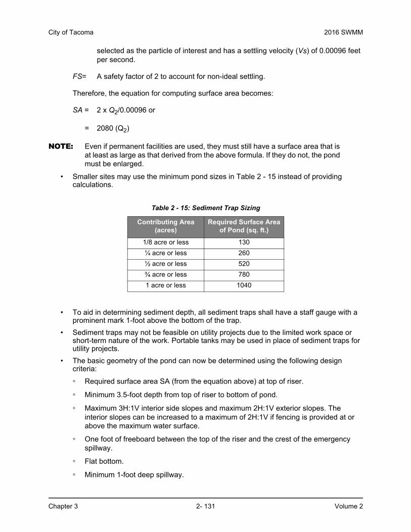
City of Tacoma 2016 SWMM
Chapter 3 2- 131 Volume 2
selected as the particle of interest and has a settling velocity (Vs) of 0.00096 feet per second.
FS= A safety factor of 2 to account for non-ideal settling.
Therefore, the equation for computing surface area becomes:
SA = 2 x Q2/0.00096 or
= 2080 (Q2)
NOTE: Even if permanent facilities are used, they must still have a surface area that is at least as large as that derived from the above formula. If they do not, the pond must be enlarged.
• Smaller sites may use the minimum pond sizes in Table 2 - 15 instead of providing calculations.
• To aid in determining sediment depth, all sediment traps shall have a staff gauge with a prominent mark 1-foot above the bottom of the trap.
• Sediment traps may not be feasible on utility projects due to the limited work space or short-term nature of the work. Portable tanks may be used in place of sediment traps for utility projects.
• The basic geometry of the pond can now be determined using the following design criteria:
◦ Required surface area SA (from the equation above) at top of riser.
◦ Minimum 3.5-foot depth from top of riser to bottom of pond.
◦ Maximum 3H:1V interior side slopes and maximum 2H:1V exterior slopes. The interior slopes can be increased to a maximum of 2H:1V if fencing is provided at or above the maximum water surface.
◦ One foot of freeboard between the top of the riser and the crest of the emergency spillway.
◦ Flat bottom.
◦ Minimum 1-foot deep spillway.
Table 2 - 15: Sediment Trap Sizing
Contributing Area (acres)
Required Surface Area of Pond (sq. ft.)
1/8 acre or less 130
¼ acre or less 260
½ acre or less 520
¾ acre or less 780
1 acre or less 1040

2016 SWMM City of Tacoma
Volume 2 2- 132 Chapter 3
◦ Length-to-width ratio between 3:1 and 6:1.
3.2.18.4 Maintenance Standards• Remove sediment from the trap when it reaches 1-foot in depth.
• Repair any damage to the pond embankments or slopes.
Figure 2 - 28. Cross-Section of a Sediment Trap
Figure 2 - 29. Sediment Trap Outlet
3.2.19 BMP C241: Temporary Sediment Pond3.2.19.1 PurposeSediment ponds remove sediment from runoff originating from disturbed areas of the site. Sediment ponds are typically designed to remove sediment no smaller than medium silt (0.02 mm). Consequently, they usually reduce turbidity only slightly.

City of Tacoma 2016 SWMM
Chapter 3 2- 133 Volume 2
3.2.19.2 Conditions of Use• Prior to leaving a construction site, stormwater runoff must pass through a sediment pond
or other appropriate sediment removal best management practice.
• Use a sediment pond where the contributing drainage area is 3 acres or more. Ponds must be used in conjunction with erosion control practices to reduce the amount of sediment flowing into the basin.
3.2.19.3 Design and Installation Specifications• Only install sediment basins on sites where failure of the structure would not result in loss
of life, damage to homes or buildings, or interruption of use or service of public roads or utilities. Also, sediment traps and ponds are attractive to children and can be very dangerous. Compliance with local ordinances regarding health and safety must be addressed. If fencing of the pond is required, show the type of fence and its location on the ESC plan.
• Structures having a maximum storage capacity at the top of the dam of 10 acre-feet (435,600 cubic feet) or more are subject to the Washington Dam Safety Regulations (Chapter 173-175 WAC).
• See Figure 2 - 30, Figure 2 - 31 and Figure 2 - 32 for details.
• If permanent detention facilities are part of the project, they may be used for sediment retention. The surface area requirements of the sediment basin must be met. This may require enlarging the permanent basin to comply with the surface area requirements. If a permanent control structure is used, it may be advisable to partially restrict the lower orifice with gravel to increase residence time while still allowing dewatering of the basin.
• Use of infiltration facilities for sedimentation basins during construction tends to clog the soils and reduce their capacity to infiltrate. If infiltration facilities are to be used, the sides and bottom of the facility must only be rough excavated to a minimum of 2 feet above final grade. Final grading of the infiltration facility shall occur only when all contributing drainage areas are fully stabilized. The infiltration pretreatment facility should be fully constructed and used with the sedimentation basin to help prevent clogging.

2016 SWMM City of Tacoma
Volume 2 2- 134 Chapter 3
Determining Pond Geometry
• Determine the required surface area at the top of the riser pipe with the equation:
SA = 2 x Q2/0.00096 or
SA= 2080 (Q2)
Where:
SA = Design surface area, in square feet, of the sediment trap measured at the invert of the weir.
Q2= Design inflow, in cubic feet per second, based on the peak discharge from the developed 2-year runoff event from the contributing drainage area as computed in the hydrologic analysis. The 10-year peak flow shall be used if the project size, expected timing and duration of construction, or downstream conditions warrant a higher level of protection. If no hydrologic analysis is required, the Rational Method may be used.
Alternatively, Q2 = Design inflow (cfs) based on the 2-year return period flowrate, predicted by WWHM for the developed (unmitigated site). Use the 10-year return period flowrate if the project size, expected timing and duration of construction, or downstream conditions warrant a higher level of protection. Q10 is the 10-year return period flowrate, predicted by WWHM.
• See BMP C240 for more information on the derivation of the surface area calculation.
• The basic geometry of the pond can now be determined using the following design criteria:
◦ Required surface area SA (from the equation above) at top of riser.
◦ Minimum 3.5-foot depth from top of riser to bottom of pond.
◦ Maximum 3H:1V interior side slopes and maximum 2H:1V exterior slopes. The interior slopes can be increased to a maximum of 2H:1V if fencing is provided at or above the maximum water surface.
◦ One foot of freeboard between the top of the riser and the crest of the emergency spillway.
◦ Flat bottom.
◦ Minimum 1-foot deep spillway.
◦ Length-to-width ratio between 3:1 and 6:1.

City of Tacoma 2016 SWMM
Chapter 3 2- 135 Volume 2
Sizing of Discharge Mechanisms
The outlet for the basin consists of a combination of principal and emergency spillways. These outlets must pass the peak runoff expected from the contributing drainage area for a 100-year storm. If, due to site conditions and basin geometry, a separate emergency spillway is not feasible, the principal spillway must pass the entire peak runoff expected from the 100-year storm. However, an attempt to provide a separate emergency spillway should always be made. The runoff calculations shall be based on the site conditions during construction. The flow through the dewatering orifice cannot be utilized when calculating the 100-year storm elevation because of its potential to become clogged; therefore, available spillway storage must begin at the principal spillway riser crest.
The principal spillway designed by the procedures contained in this standard will result in some reduction in the peak rate of runoff. However, the riser outlet design will not adequately control the basin discharge to the predevelopment discharge limitations as stated in Minimum Requirement #7: Flow Control. However, if the basin for a permanent stormwater detention pond is used for a temporary sedimentation basin, the control structure for the permanent pond can be used to maintain predevelopment discharge limitations. The size of the basin, the expected life of the construction project, the anticipated downstream effects, and the anticipated weather conditions during construction should be considered to determine the need of additional discharge control. See Figure 2 - 33 for riser inflow curves.
Principal Spillway: Determine the required diameter for the principal spillway (riser pipe). The diameter shall be the minimum necessary to pass the pre-developed 10-year peak flow (Q10). If using WWHM, Q10 is the 10-year return period flowrate. Use Figure 2 - 33 to determine this diameter (h = 1-foot).
NOTE: A permanent control structure may be used instead of a temporary riser.
Emergency Overflow Spillway: Determine the required size and design of the emergency overflow spillway for the developed 100-year peak flow using the method contained in Volume 3. If using WWHM, Q100 is the 100-year return period flowrate.
Dewatering Orifice: Determine the size of the dewatering orifice(s) (minimum 1-inch diameter) using a modified version of the discharge equation for a vertical orifice and a basic equation for the area of a circular orifice. Determine the required area of the orifice with the following equation:
Where:
Ao= orifice area (square feet)As= pond surface area (square feet)h= head of water above orifice (height of riser in feet)T= dewatering time (24 hours)g= acceleration of gravity (32.2 feet per second squared)D= orifice diameter (inches)
Convert the required surface area to the required diameter D of the orifice:
5.0
5.0
3600x6.0
)2(
Tg
hAA so

2016 SWMM City of Tacoma
Volume 2 2- 136 Chapter 3
The vertical, perforated tubing connected to the dewatering orifice must be at least 2 inches larger in diameter than the orifice to improve flow characteristics. The size and number of perforations in the tubing shall be large enough so the tubing does not restrict flow. The orifice shall control the flow rate.
Additional Design Specifications
The pond shall be divided into two roughly equal volume cells by a permeable divider that will reduce turbulence while allowing movement of water between cells. The divider shall be at least one-half the height of the riser and a minimum of one foot below the top of the riser. Wire-backed, 2- to 3-foot high, extra strength filter fabric supported by treated 4"x4"s can be used as a divider. If the pond is more than 6 feet deep, a different mechanism must be proposed. A riprap embankment is one acceptable method of separation for deeper ponds. Other designs that satisfy the intent of this provision are allowed as long as the divider is permeable, structurally sound, and designed to prevent erosion under or around the barrier.
To aid in determining sediment depth, prominently mark one-foot intervals on the riser.
If an embankment height of more than 6 feet is proposed, the pond must comply with the criteria contained in Volume 3 regarding dam safety for detention BMPs.
The most common structural failure of sedimentation basins is caused by piping. Piping refers to two phenomena: (1) water seeping through fine-grained soil, eroding the soil grain by grain and forming pipes or tunnels and (2) water under pressure flowing upward through a granular soil with a head of sufficient magnitude to cause soil grains to lose contact and capability for support.
The most critical construction sequences to prevent piping will be:
• Tight connections between the riser and barrel and other pipe connections.
• Adequate anchoring of the riser.
• Proper soil compaction of the embankment and riser footing.
• Proper construction of anti-seep devices.
3.2.19.4 Maintenance Standards• Remove sediment from the pond when it reaches 1–foot in depth.
• Repair any damage to the pond embankments or slopes.
oo AA
D x54.13x24

City of Tacoma 2016 SWMM
Chapter 3 2- 137 Volume 2
Figure 2 - 30. Sediment Pond
Figure 2 - 31. Sediment Pond Cross Section

2016 SWMM City of Tacoma
Volume 2 2- 138 Chapter 3
Figure 2 - 32. Sediment Pond Riser Detail

City of Tacoma 2016 SWMM
Chapter 3 2- 139 Volume 2
Figure 2 - 33. Riser Inflow Curves

2016 SWMM City of Tacoma
Volume 2 2- 140 Chapter 3
3.2.20 BMP C250: Construction Stormwater Chemical Treatment3.2.20.1 PurposeThis BMP applies when using stormwater chemicals in batch treatment or flow-through treatment.
Turbidity is difficult to control once fine particles are suspended in stormwater runoff from a construction site. Sedimentation ponds are effective at removing larger particulate matter by gravity settling, but are ineffective at removing smaller particulates such as clay and fine silt. Traditional erosion and sediment control BMPs may not be adequate to ensure compliance with the water quality standards for turbidity in the receiving water.
3.2.20.2 Conditions of UseFormal written approval from Ecology and the City is required for the use of chemical treatment regardless of site size. When approved, include the chemical treatment system in the Stormwater Pollution Prevention Plan (SWPPP).
3.2.20.3 Design and Installation SpecificationsSee Appendix B for background information on chemical treatment.
Criteria for Chemical Treatment Product Use
Chemically treated stormwater discharged from construction sites must be nontoxic to aquatic organisms. The Chemical Technology Assessment Protocol - Ecology (CTAPE) must be used to evaluate chemicals proposed for stormwater treatment. Only chemicals approved by Ecology under the CTAPE may be used for stormwater treatment. The approved chemicals, their allowable application techniques (batch treatment or flow-through treatment), allowable application rates, and conditions of use can be found at the Department of Ecology Emerging Technologies website: http://www.ecy.wa.gov/programs/wq/stormwater/newtech/index.html
Treatment System Design Considerations
• The design and operation of a chemical treatment system should take into consideration the factors that determine optimum, cost-effective performance. It is important to recognize the following:
• Only Ecology approved chemicals may be used and must follow approved dose rates.
• The pH of the stormwater must be in the proper range for the polymers to be effective, which is typically 6.5 to 8.5.
• The coagulant must be mixed rapidly into the water to ensure proper dispersion.
• A flocculation step is important to increase the rate of settling, to produce the lowest turbidity, and to keep the dosage rate as low as possible.
• Too little energy input into the water during the flocculation phase results in flow that are too small and/or insufficiently dense. Too much energy can rapidly destroy floc as it is formed.
• Care must be taken in the design of the withdrawal system to minimize outflow velocities and to prevent floc discharge. Discharge from a batch treatment system should be directed through a physical filter such as a vegetated swale that would catch any unintended floc discharge. Currently, flow-through systems always discharge through the chemically enhanced sand filtration system.

City of Tacoma 2016 SWMM
Chapter 3 2- 141 Volume 2
• System discharge rates must take into account downstream conveyance integrity.
Polymer Batch Treatment Process Description
A batch chemical treatment system consists of the stormwater collection system (either temporary diversion or the permanent site drainage system), an untreated stormwater storage pond, pumps, a chemical feed system, treatment cells, and interconnecting piping.
The batch treatment system shall use a minimum of two lined treatment cells in addition to the untreated stormwater storage pond. Multiple treatment cells allow for clarification of treated water while other cells are being filled or emptied. Treatment cells may be ponds or tanks. Ponds with constructed earthen embankments greater than six feet high require special engineering analyses.
Stormwater is collected at interception point(s) on the site and is diverted by gravity or by pumping to an untreated stormwater storage pond or other untreated stormwater holding area. The stormwater is stored until treatment occurs. It is important that the holding pond be large enough to provide adequate storage.
The first step in the treatment sequence is to check the pH of the stormwater in the untreated stormwater storage pond. The pH is adjusted by the application of carbon dioxide or a base until the stormwater in the storage pond is within the desired pH range, 6.5 to 8.5. When used, carbon dioxide is added immediately downstream of the transfer pump. Typically sodium bicarbonate (baking soda) is used as a base, although other bases may be used. When needed, base is added directly to the untreated stormwater storage pond. The stormwater is recirculated with the treatment pump to provide mixing in the storage pond. Initial pH adjustments should be based on daily bench tests. Further pH adjustments can be made at any point in the process.
Once the stormwater is within the desired pH range (dependant on polymer being used), the stormwater is pumped from the untreated stormwater storage pond to a treatment cell as polymer is added. The polymer is added upstream of the pump to facilitate rapid mixing.
After polymer addition, the water is kept in a lined treatment cell for clarification of the sediment-floc. In a batch mode process, clarification typically takes from 30 minutes to several hours. Prior to discharge samples are withdrawn for analysis of pH and turbidity. If both are acceptable, the treated water is discharged.
Several configurations have been developed to withdraw treated water from the treatment cell. The original configuration is a device that withdraws the treated water from just beneath the water surface using a float with adjustable struts that prevent the float from settling on the cell bottom (Figure 2 - 34). This reduces the possibility of picking up sediment-floc from the bottom of the pond. The struts are usually set at a minimum clearance of about 12 inches; that is, the float will come within 12 inches of the bottom of the cell. Other systems have used vertical guides or cables which constrain the float, allowing it to drift up and down with the water level. More recent designs have an H-shaped array of pipes, set on the horizontal.

2016 SWMM City of Tacoma
Volume 2 2- 142 Chapter 3
Figure 2 - 34. Floating Platform with Struts
This scheme provides for withdrawal from four points rather than one. This configuration reduces the likelihood of sucking settled solids from the bottom. It also reduces the tendency for a vortex to form. Inlet diffusers - long floating or fixed pipes with many small holes in them - are also an option.
Safety is a primary concern. Design should consider the hazards associated with operations, such as sampling. Facilities should be designed to reduce slip hazards and drowning. Tanks and ponds should have life rings, ladder, or steps extending from the bottom to the top.
Polymer Flow-Through Treatment Process Description
At a minimum, a flow-through chemical treatment system consists of the stormwater collection system (either temporary diversion or the permanent site drainage system), an untreated stormwater storage pond, and the chemically enhanced sand filtration system.
Stormwater is collected at interception point(s) on the site and is diverted by gravity or by pumping to an untreated stormwater storage pond or other untreated stormwater holding area. The stormwater is stored until treatment occurs. It is important that the holding pond be large enough to provide adequate storage.
Stormwater is then pumped from the untreated stormwater storage pond to the chemically enhanced sand filtration system where polymer is added. Adjustments to pH may be necessary before chemical addition. The sand filtration system continually monitors the stormwater for turbidity and pH. If the discharge water is ever out of an acceptable range for turbidity or pH, the water is recycled to the untreated stormwater pond where it can be retreated.
City of Tacoma 2016 SWMM
Chapter 3 2- 143 Volume 2
Equipment
For batch treatment and flow-through treatment, the following equipment should be located in a lockable shed:
• The chemical injector
• Secondary non-corrosive containment for acid, caustic, buffering compound, and treatment chemical
• Emergency shower and eyewash
• Monitoring equipment
System Sizing
Certain sites are required to implement flow control for the developed sites. These sites must also control stormwater release rates during construction. System sizing is dependent on flow control requirements.
Sizing Criteria for Batch Treatment Systems for Flow Control Exempt Water Bodies
• The total volume of the untreated stormwater storage pond and treatment ponds or tanks must be large enough to treat the volume of stormwater that is produced during multiple day storm events. At a minimum, size the untreated storage pond to hold 1.5 times the runoff volume of the 10-year, 24-hour storm event assuming a Type 1A rainfall distribution (3.0-inches). Provide bypass around the chemical treatment system to accommodate extreme storm events. Calculate runoff volumes using the methods in Volume 3, Chapter 3. Use worst-case land cover conditions (i.e., producing the most runoff) for analyses (in most cases, this would be the land cover conditions just prior to final landscaping).
• Primary settling should be encouraged in the untreated stormwater storage pond. A forebay with access for maintenance is beneficial.
• There are two opposing considerations in sizing the treatment cells. A larger cell is able to treat a larger volume of water each time a batch is processed. However, the larger the cell the longer the time is required to empty the cell. A larger cell may also be less effective at flocculation and therefore require a longer settling time. The simplest approach to sizing the treatment cell is to multiply the allowable discharge flowrate times the desired drawdown time. A 4-hour drawdown time allows one batch per cell per 8-hour work period, given 1 hour of flocculation followed by 2 hours of settling.
• If the discharge is directly to a lake, flow control exempt receiving water, or to an infiltration system, there is no discharge flow limit.
• Ponds sized for flow control water bodies must be sized accoding to the Sizing Criteria for Flow Control Water Bodies below. If the sizing criteria shows a smaller pond size than required for Sizing Criteria for Flow Control Water Bodies, use the larger pond size.
Sizing Criteria for Flow-Through Treatment for Flow Control Exempt Water Bodies:
• When sizing storage ponds or tanks for flow-through systems for flow control exempt water bodies, the treatment system capacity should be a factor. The untreated stormwater storage pond or tank should be sized to hold 1.5 times the runoff volume of the 10-year, 24-hour storm event assuming a Type 1A rainfall distribution (3.0-inches) minus the treatment system flowrate for an 8-hour period. For a chitosan-enhanced sand filtration system, the treatment system flowrate should be sized using a hydraulic loading
2016 SWMM City of Tacoma
Volume 2 2- 144 Chapter 3
rate between 6-8 gpm/ft2. Other hydraulic loading rates may be appropriate for other systems. Bypass should be provided around the chemical treatment system to accommodate extreme storms. Runoff volume shall be calculated using the methods presented in Volume 3. Worst-case land cover conditions (i.e. producing the most runoff) should be used for analyses (in most cases, this would be the land cover conditions just prior to final landscaping).
Sizing Criteria for Flow Control Water Bodies:
• Sites that must implement flow control for the developed site condition must also control stormwater release rates during construction. Construction site stormwater discharges shall not exceed the discharge durations of the predeveloped condition for the range of predeveloped discharge rates from ½ of the 2-year flow through the 10-year flow as predicted by WWHM. The predeveloped condition to be matched shall be the land cover condition immediately prior to the development project. This restriction on release rates can affect the size of the storage pond and treatment cells.
• The following is how WWHM can be used to determine the release rates from the chemical treatment systems:
1. Determine the predeveloped flow durations to be matched by entering the land use area under the “Predeveloped” scenario in WWHM. The default flow range is from ½ of the 2-year flow through the 10-year flow.
2. Enter the post developed land use area in the “Developed Unmitigated” scenario in WWHM.
3. Copy the land use information for the “Developed Unmitigated” to “Developed Mitigated” scenario.
4. While in the “Developed Mitigated” scenario, add a pond element under the basin element containing the post-developed land use areas. This pond element represents information on the available untreated stormwater storage and discharge from the chemical treatment system. In cases where the discharge from the chemical treatment is controlled by a pump, a stage/storage/discharge (SSD) table representing the pond must be generated outside WWHM and imported into WWHM. WWHM can route the runoff from the post-developed condition through this SSD table (the pond) and determine compliance with the flow duration standard. This would be an iterative design procedure where if the initial SSD table proved to be inadequate, the designer would have to modify the SSD table outside WWHM and reimport in WWHM and route the runoff through it again. The iteration will continue until a pond that complies with the flow duration standard is correctly sized.
Notes on SSD table characteristics:
◦The pump discharge rate would likely be initially set at just below ½ of the 2-year flow from the pre-developed condition. As runoff coming into the untreated stormwater storage pond increases and the available untreated stormwater storage volume gets used up, it would be necessary to increase the pump discharge rate above ½ of the 2-year. The increase(s) above ½ of the 2-year must be such

City of Tacoma 2016 SWMM
Chapter 3 2- 145 Volume 2
that they provide some relief to the untreated stormwater storage needs but at the same time will not cause violations of the flow duration standard at the higher flows. The final design SSD table will identify the appropriate pumping rates and the corresponding stage and storages.
◦When building such a flow control system, the design must ensure that any automatic adjustments to the pumping rates will be as a result of the changes to the available storage in accordance with the final design SSD table.
• It should be noted that the above procedures would be used to meet the flow control requirements. The chemical treatment system must be able to meet the runoff treatment requirements. It is likely that the discharge flowrate of ½ of the 2-year or more may exceed the treatment capacity of the system. If that is the case, the untreated stormwater discharge rate(s) (i.e., influent to the treatment system) must be reduced to allow proper treatment. Any reduction in the flows will likely result in the need for a larger untreated stormwater storage volume.
• If the discharge is to a municipal storm drainage system, the allowable discharge rate may be limited by the capacity of the public system. It may be necessary to clean the municipal storm drainage system prior to the start of the discharge to prevent scouring solids from the drainage system. If the municipal storm drainage system discharges to a water body that is not flow control exempt, the project site is subject to flow control requirements.
• If system design does not allow you to discharge at the slower rates as described above and if the site had a retention or detention pond that will serve the planned development, the discharge from the treatment system may be directed to the permanent retention/detention pond to comply with the flow control requirement. In this case, the untreated stormwater storage pond and treatment system will be sized according to the sizing criteria for flow-through system for flow control exempt water bodies described earlier except all discharge (water passing through the treatment system and stormwater bypassing the treatment system) will be directed into the permanent retention/detention pond. If site constraints make locating the untreated stormwater storage pond difficult, the permanent retention/detention pond may be divided to serve as the untreated stormwater storage pond and the post-treatment flow control pond. A berm or barrier must be used in this case so the untreated water does not mix with the treated water. Both untreated stormwater storage requirements, and adequate post-treatment flow control must be achieved. The post-treatment flow control pond’s revised dimensions must be entered into the WWHM and the WWHM must be run to confirm compliance with the flow control requirements.
3.2.20.4 MonitoringConduct the following monitoring. Record test results on a daily log kept on site. Additional testing may be required by the NPDES permit based on site conditions.
Operational Monitoring:
• Total volume treated and discharged
• Flow must be continuously monitored and recorded at not greater than 15-minute intervals
• Type and amount of chemical used for pH adjustment, if any

2016 SWMM City of Tacoma
Volume 2 2- 146 Chapter 3
• Quantity of chemical used for treatment
• Settling time
Compliance Monitoring
• Influent and effluent pH and turbidity must be continuously monitored and recorded at not greater than 15-minute intervals.
• pH and turbidity of the receiving water
Biomonitoring
• Treated stormwater must be non-toxic to aquatic organisms. Treated stormwater must be tested for aquatic toxicity or residual chemical content. Frequency of biomonitoring will be determined by Ecology.
• Residual chemical tests must be approved by Ecology prior to their use.
• If testing treated stormwater for aquatic toxicity, you must test for acute (lethal) toxicity. Bioassays shall be conducted by a laboratory accredited by Ecology, unless otherwise approved by Ecology. Acute toxicity tests shall be conducted per the CTAPE protocol.
Discharge Compliance
• Prior to discharge, treated stormwater must be sampled and tested for compliance with pH and turbidity limits. These limits may be established by the Construction Stormwater General Permit, or a site-specific discharge permit. Sampling and testing for other pollutants may also be necessary at some sites. pH must be within the range of 6.5 to 8.5 standard units and not cause a change in the pH of the receiving water of more than 0.2 standard units.
• Treated stormwater samples and measurements shall be taken from the discharge pipe or another location representative of the nature of the treated stormwater discharge. Compliance with the water quality standards is determined in the receiving water.
Operator Training
• Each contractor who intends to use chemical treatment shall be trained by an experienced contractor. Each site using chemical treatment must have an operator trained and certified by an organization approved by Ecology.
Standard BMPs
• Surface stabilization BMPs should be implemented on site to prevent significant erosion. All sites shall use a truck wheel wash to prevent tracking of sediment off site.
Sediment Removal and Disposal:
• Remove sediment from the storage or treatment cells as necessary. Typically, sediment removal is required at least once during a wet season and at the decommissioning of the cells. Sediment remaining in the cells between batches may enhance the settling process and reduce the required chemical dosage.
• Sediment that is known to be non-toxic may be incorporated into the site away from drainages.

City of Tacoma 2016 SWMM
Chapter 3 2- 147 Volume 2
3.2.21 BMP C251: Construction Stormwater Filtration 3.2.21.1 PurposeFiltration removes sediment from runoff originating from disturbed areas of the site.
3.2.21.2 Conditions of UseTraditional BMPs used to control soil erosion and sediment loss from sites under development may not be adequate to ensure compliance with the water quality standard for turbidity in the receiving water. Filtration may be used in conjunction with gravity settling to remove sediment as small as fine silt (0.5 µm). The reduction in turbidity will be dependent on the particle size distribution of the sediment in the stormwater. In some circumstances, sedimentation and filtration may be sufficient to achieve compliance with the water quality standard for turbidity.
The use of construction stormwater filtration does not require approval from Ecology as long as treatment chemicals are not used. Filtration in conjunction with polymer treatment requires testing under the Chemical Technology Assessment Protocol – Ecology (CTAPE) before it can be initiated. Approval from the appropriate regional Ecology office must be obtained at each site where polymers use is proposed prior to system start-up. For more guidance on stormwater chemical treatment see BMP C250.
3.2.21.3 Background InformationFiltration with sand media has been used for over a century to treat water and wastewater. The use of sand filtration for treatment of stormwater has developed recently, generally to treat runoff from streets, parking lots, and residential areas. The application of filtration to construction stormwater is currently under development.
3.2.21.4 Design and Installation SpecificationsTwo types of filtration systems may be applied to construction stormwater treatment: rapid and slow. Rapid sand filters are the typical system used for water and wastewater treatment. They can achieve relatively high hydraulic flow rates, on the order of 2 to 20 gpm/sf, because they have automatic backwash systems to remove accumulated solids. In contrast, slow sand filters have very low hydraulic rates, on the order of 0.02 gpm/sf, because they do not have backwash systems. To date, slow sand filtration has generally been used to treat stormwater. Slow sand filtration is mechanically simple in comparison to rapid sand filtration but requires a much larger filter area.
Filtration Equipment
Sand media filters are available with automatic backwashing features that can filter to 50 µm particle size. Screen or bag filters can filter down to 5 µm. Fiber wound filters can remove particles down to 0.5 µm. Filters should be sequenced from the largest to the smallest pore opening. Sediment removal efficiency will be related to particle size distribution in the stormwater.
Treatment Process Description
Stormwater is collected at interception point(s) on the site and is diverted to an untreated stormwater sediment pond or tank for removal of large sediment and storage of the stormwater before it is treated by the filtration system. The untreated stormwater is pumped from the trap, pond, or tank through the filtration system in a rapid sand filtration system. Slow sand filtration systems are designed as flow through systems using gravity.

2016 SWMM City of Tacoma
Volume 2 2- 148 Chapter 3
Sizing Criteria for Flow-Through Treatment Systems for Flow Control Exempt Water Bodies
When sizing storage ponds or tanks for flow-through systems for flow control exempt water bodies, the treatment system capacity should be a factor. The untreated stormwater storage pond or tank should be sized to hold 1.5 times the runoff volume of the 10-year, 24-hour storm event assuming a Type 1A rainfall distribution (3.0-inches) minus the treatment system flowrate for an 8-hour period. For a chitosan-enhanced sand filtration system, the treatment flowrate should be sized using a hydraulic loading rate between 6-8 gpm/ft². Other hydraulic loading rates may be more appropriate for other systems. Bypass should be provided around the chemical treatment system to accommodate extreme storms. Runoff volumes shall be calculated using the methods presented in Volume 3, Chapter 3. Worst-case conditions (i.e., producing the most runoff) should be used for analyses (most likely conditions present prior to final landscaping).
Sizing Criteria for Flow Control Waters:
Sites that must implement flow control for the developed site condition must also control stormwater release rates during construction. Construction site stormwater discharges shall not exceed the discharge durations of the pre-developed condition for the range of pre-developed discharge rates from 1/2 of the 2-year flow through the 10-year flow as predicted by WWHM. The pre-developed condition to be matched shall be the land cover condition immediately prior to the development project. This restriction on release rates will affect the size of the sediment pond, the filtration system, and the flow rate through the filter system.
The following is how WWHM can be used to determine the release rates from the filtration systems:
1. Determine the pre-developed flow durations to be matched by entering the land use area under the “Pre-developed” scenario in WWHM. The default flow range is from ½ of the 2-year flow through the 10-year flow.
2. Enter the post developed land use area in the “Developed Unmitigated” scenario in WWHM.
3. Copy the land use information from the “Developed Unmitigated” to “Developed Mitigated” scenario.
4. There are two possible ways to model stormwater filtration systems:
a. The stormwater filtration system uses a storage pond/tank and the discharge from this pond/tank is pumped to one or more filters. In-line filtration chemicals would be added to the flow right after the pond/tank and before the filter(s). Because the discharge is pumped, WWHM can’t generate a stage/storage/discharge (SSD) table for this system. This system is modeled the same way as described in BMP C250 and is as follows:
While in the “Developed Mitigated” scenario, add a pond element under the basin element containing the post-developed land use areas. This pond element represents information on the available storage and discharge from the filtration system. In cases where the discharge from the filtration system is controlled by a pump, a stage/storage/discharge (SSD) table representing the pond must be generated outside WWHM and imported into WWHM. WWHM can route the runoff from the post-developed condition through this SSD table (the pond) and determine compliance with the flow duration standard. This would be

City of Tacoma 2016 SWMM
Chapter 3 2- 149 Volume 2
an iterative design procedure where if the initial SSD table proved to be out of compliance, the designer would have to modify the SSD table outside WWHM and re-import in WWHM and route the runoff through it again. The iteration will continue until a pond that enables compliance with the flow duration standard is designed.
Notes on SSD Table Characteristics
• The pump discharge rate would likely be initially set at just below ½ of the 2-year flow from the pre-developed condition. As runoff coming to the storage pond increases and the available storage volume gets used up, it would be necessary to increase the pump discharge rate above ½ of the 2-year. The increase(s) above ½ of the 2-year must be such that they provide some relief to the storage needs but at the same time they will not cause violations of the flow duration standard at the higher flows. The final design SSD table will identify the appropriate pumping rates and the corresponding stage and storages.
• When building such a flow control system, the design must ensure that any automatic adjustments to the pumping rates will be as a result of changes to the available storage in accordance with the final design SSD table.
b. The stormwater filtration system uses a storage pond/tank and the discharge from this pond/tank gravity flows to the filter. This is usually a slow sand filter system and it is possible to model it in WWHM as a Filter element or as a combination of Pond and Filter element placed in series. The stage/storage/discharge table(s) may then be generated within WWHM as follows:
(i) While in the “Developed Mitigated” scenario, add a Filter element under the basin element containing the post-developed land use areas. The length and width of this filter element would have to be the same as the bottom length and width of the upstream storage pond/tank.
(ii) In cases where the length and width of the filter is not the same as those for the bottom of the upstream storage tank/pond, the treatment system may be modeled as a Pond element followed by a Filter element. By having these two elements, WWHM would then generate a SSD table for the storage pond which then gravity flows to the Filter element. The Filter element downstream of the storage pond would have a storage component through the media, and an overflow component for when the filtration capacity is exceeded.
WWHM can route the runoff from the post-developed condition through the treatment systems in 4b and determine compliance with the flow duration standard. This would be an iterative design procedure where if the initial sizing estimates for the treatment system proved to be inadequate, the designer would have to modify the system and route the runoff through it again. The iteration would continue until compliance with the flow duration standard is achieved.
5. It should be noted that the above procedures would be used to meet the flow control requirements. The filtration system must be able to meet the runoff treatment requirements. It is likely that the discharge flow rate of ½ of the 2-year or more may exceed the treatment
2016 SWMM City of Tacoma
Volume 2 2- 150 Chapter 3
capacity of the system. If that is the case, the discharge rate(s) must be reduced to allow proper treatment. Any reduction in the flows would likely result in the need for a larger storage volume.
If the system does not allow you to discharge at the slower rate as described above and if the site has a retention or detention pond that will serve the planned development, the discharge from the treatment system may be directed to the permanent retention/detention pond to comply with the flow control requirements. In this case, the untreated stormwater storage pond and treatment system will be sized according to the sizing criteria for flow-through treatment systems for flow control exempt waterbodies except all discharges (water passing through the treatment system and stormwater bypassing the treatment system) will be directed into the permanent retention/detention pond. If site constraints make locating the untreated stormwater storage pond difficult, the permanent retention/detention pond may be divided to serve as the untreated stormwater discharge pond and the post-treatment flow control pond. A berm or barrier must be used in this case so the untreated water does not mix with the treated water. Both untreated stormwater storage requirements, and adequate post-treatment flow control must be achieved. The post-treatment flow control pond’s revised dimensions must be entered into the WWHM and the WWHM must be run to confirm compliance with the flow control requirements.
3.2.21.5 Maintenance Standards• Rapid sand filters typically have automatic backwash systems that are triggered by a pre-
set pressure drop across the filter. If the backwash water volume is not large or substantially more turbid than the untreated stormwater stored in the holding pond or tank, backwash return to the untreated stormwater pond or tank may be appropriate. However, land application or another means of treatment and disposal may be necessary.
• Clean and/or replace screen, bag, and fiber filters when they become clogged.
• Remove sediment from the storage and/or treatment ponds as necessary. Typically, sediment removal is required once or twice during a wet season and at the decommissioning of the ponds.
3.2.22 BMP C252: High pH Neutralization using CO2
3.2.22.1 DescriptionWhen pH levels in stormwater rise above 8.5 it is necessary to lower the pH levels to the acceptable range of 6.5 to 8.5, this process is called pH neutralization. pH neutralization involves the use of solid or compressed carbon dioxide gas in water requiring neutralization. Neutralized stormwater may be discharged to surface waters under the General Construction NPDES permit but neutralized process wastewater must be managed to prevent discharge to surface waters. Process wastewater includes wastewaters such as concrete truck wash-out, hydro-demolition, or saw-cutting slurry. Any stormwater contaminated during concrete work is considered process wastewater and must not be discharged to surface water.
Reason for pH neutralization
A pH level range of 6.5 to 8.5 is typical for most natural watercourses, and this neutral pH is required for the survival of aquatic organisms. Should the pH rise or drop out of this range, fish and other aquatic organisms may become stressed and may die.
City of Tacoma 2016 SWMM
Chapter 3 2- 151 Volume 2
Calcium hardness can contribute to high pH values and cause toxicity that is associated with high pH conditions. A high level of calcium hardness in waters of the state is not allowed.
The water quality standard for pH in Washington State is in the range of 6.5 to 8.5.
Groundwater standard for calcium and other dissolved solids in Washington State is less than 500 mg/l.
Causes of high pH
High pH at construction sites is most commonly caused by the contact of stormwater with poured or recycled concrete, cement, mortars, and other Portland cement or lime-containing construction materials. (See BMP C151: Concrete Handling for more information on concrete handling procedures). The principal caustic agent in cement is calcium hydroxide (free lime).
Advantages of CO2 Sparging
• Rapidly neutralizes high pH water.
• Cost effective and safer to handle than acid compounds.
• CO2 is self-buffering. It is difficult to overdose and create harmfully low pH levels.
• Material is readily available.
The Chemical Process
When carbon dioxide (CO2) is added to water (H2O), carbonic acid (H2CO3) is formed which can
further dissociate into a proton (H+) and a bicarbonate anion (HCO3-) as shown below:
CO2 + H2O H2CO3 H+ + HCO3-
The free proton is a weak acid that can lower the pH.
Water temperature has an effect on the reaction as well. The colder the water temperature is the slower the reaction occurs and the warmer the water temperature is the quicker the reaction occurs. Most construction applications in Washington State have water temperatures in the 50°F or higher range so the reaction is almost simultaneous.
3.2.22.2 Treatment Procedures High pH water may be treated using continuous treatment, continuous discharge systems. These manufactured systems continuously monitor influent and effluent pH to ensure that pH values are within an acceptable range before being discharged. All systems must have fail safe automatic shut off switches in the event that pH is not within the acceptable discharge range. Only trained operators may operate manufactured systems. System manufacturers often provide trained operators or training on their devices.
The following procedure may be used when not using a continuous discharge system:
• Prior to treatment, the appropriate jurisdiction should be notified in accordance with the regulations set by the jurisdiction.
• Every effort should be made to isolate the potential high pH water in order to treat it separately from other stormwater onsite.
• Water should be stored in an acceptable storage facility, detention pond, or containment cell prior to treatment.
2016 SWMM City of Tacoma
Volume 2 2- 152 Chapter 3
• Transfer water to be treated to the treatment structure. Ensure that treatment structure size is sufficient to hold the amount of water that is to be treated. Do not fill tank completely, allow at least 2 feet of freeboard.
• The operator samples the water for pH and notes the clarity of the water. As a rule of thumb, less CO2 is necessary for clearer water. This information should be recorded.
• In the pH adjustment structure, add CO2 until the pH falls in the range of 6.9-7.1. Remember that pH water quality standards apply so adjusting pH to within 0.2 pH units of receiving water (background pH) is recommended. It is unlikely that pH can be adjusted to within 0.2 pH units using dry ice. Compressed carbon dioxide gas should be introduced to the water using a carbon dioxide diffuser located near the bottom of the tank, this will allow carbon dioxide to bubble up through the water and diffuse more evenly.
• Slowly release the water to discharge making sure water does not get stirred up in the process. Release about 80% of the water from the structure leaving any sludge behind.
• Discharge treated water through a pond or drainage system.
• Excess sludge needs to be disposed of properly as concrete waste. If several batches of water are undergoing pH treatment, sludge can be left in treatment structure for the next batch treatment. Dispose of sludge when it fills 50% of tank volume.
Sites that must implement flow control for the developed site must also control stormwater release rates during construction. All treated stormwater must go through a flow control facility before being released to surface waters which require flow control.
3.2.22.3 Safety and Materials Handling• All equipment should be handled in accordance with OSHA rules and regulations.
• Follow manufacturer guidelines for materials handling.
3.2.22.4 Operator RecordsEach operator should provide:
• A diagram of the monitoring and treatment equipment
• A description of the pumping rates and capacity the treatment equipment is capable of treating.
Each operator should keep a written record of the following:
• Client name and phone number
• Date of treatment
• Weather conditions
• Project name and location
• Volume of water treated
• pH of untreated water
• Amount of CO2 needed to adjust water to a pH range of 6.9-7.1
• pH of treated water
• Discharge point location and description
A copy of this record should be given to the client/contractor who should retain the record for three years.

City of Tacoma 2016 SWMM
Chapter 3 2- 153 Volume 2
3.2.23 BMP C253: pH Control for High pH Water3.2.23.1 DescriptionWhen pH levels in stormwater rise above 8.5 it is necessary to lower the pH levels to the acceptable range of 6.5 to 8.5, this process is called pH neutralization. Stormwater with pH levels exceeding water quality standards may be treated by infiltration, dispersion in vegetation or compost-amended soils meeting BMP L613 Post-Construction Soil Quality and Depth, pumping to a sanitary sewer, disposal at a permitted concrete batch plant with pH neutralization capabilities, or carbon dioxide sparging. BMP C252 provides guidance for carbon dioxide sparging.
Reason for pH neutralization
A pH level between 6.5 and 8.5 is typical for most natural watercourses, and this pH range is required for the survival of aquatic organisms. Should the pH rise or drop out of this range, fish and other aquatic organisms may become stressed and may die.
Causes of high pH
High pH levels at construction sites are most commonly caused by the contact of stormwater with poured or recycled concrete, cement, mortars, and other Portland cement or lime-containing construction materials. (See BMP C151: Concrete Handling for more information on concrete handling procedures). The principal caustic agent in cement is calcium hydroxide (free lime).
3.2.23.2 Disposal Methods
Infiltration
• Infiltration is only allowed if soil type allows all water to infiltrate (no surface runoff) without causing or contributing to a violation of surface or groundwater quality standards.
• Infiltration techniques should be consistent with Volume 5, Chapter 5.
Dispersion
• Use BMP L614 Full Dispersion
Sanitary Sewer Disposal
• A Special Approved Discharge (SAD) permit will be required for discharge to the sanitary sewer. Contact Source Control at 253.591.5588 for information on the SAD permit.
Concrete Batch Plant Disposal
• Only permitted facilities may accept high pH water.
• Facility should be contacted before treatment to ensure they can accept the high pH water.
Stormwater Discharge
Any pH treatment options that generate treated water that must be discharged off site are subject to flow control requirements. Sites that must implement flow control for the developed site must also control stormwater release rates during construction. All treated stormwater must go through a flow control facility before being released to surface waters which require flow control.

2016 SWMM City of Tacoma
Volume 2 2- 154 Chapter 3
This Page Intentionally Left Blank

City of Tacoma 2016 SWMM
Appendix A 2- 155 Volume 2
Appendix A Standard Notes for Temporary Erosion and Sedimentation Control Plans
The following standard notes shall be included on project drawings for projects exceeding the thresholds for a short form SWPPP and are recommended to be included on drawings for all projects. Plans shall identify the name and phone number of the person or firm responsible for the preparation and maintenance of the erosion control plan.
Standard TESC Notes
1. The implementation of these TESC plans and the construction, maintenance, replacement, and upgrading of TESC facilities is the responsibility of the applicant/contractor until all construction is completed and approved, vegetation/landscaping is established and the entire site is stabilized.
2. The boundaries of the clearing limits shown on this plan shall be clearly marked in the field prior to construction. During the construction period, no disturbance beyond the clearing limits shall be permitted. The marking shall be maintained by the applicant/contractor for the duration of construction.
3. The TESC facilities shown on this plan shall be constructed prior to and/or in conjunction with all clearing and grading activities, and in such a manner as to ensure that sediment and sediment laden water do not enter the drainage system or roadways, or violate applicable water standards.
4. The TESC facilities shown on this plan are the minimum requirements for anticipated site conditions. During the construction period, TESC facilities shall be upgraded as needed for unexpected storm events and to ensure that sediment and sediment-laden water do not leave the site.
5. The CESCL, CPESC, or ESC Lead shall be identified in the SWPPP and shall be onsite or on-call at all times.
6. The CESCL, CPESC, or ESC Lead must be knowledgeable in the principles and practices of erosion and sediment control and have the skills to assess:
a. Site conditions and construction activities that could impact the quality of stormwater.
b. Effectiveness of erosion and sediment control measures used to control the quality of stormwater discharges.
7. The CESCL, CPESC, or ESC Lead must examine stormwater visually for the presence of suspended sediment, turbidity, discoloration, and oil sheen and evaluate the effectiveness of BMPS to determine if it is necessary to install, maintain, or repair BMPs.
8. The CESCL, CPESC, or ESC Lead must inspect all areas disturbed by construction activities, all BMPs, and all stormwater discharge points at least once every calendar week and within 24 hours of any discharge from the site. (Individual discharge events that last more than one day do not require daily inspections). The CESCL or inspector may reduce the inspection frequency for temporary stabilized, inactive sites to once every calendar month.
9. Construction site operators must correct any problems identified by the CESCL, CPESC, or ESC Lead by:

2016 SWMM City of Tacoma
Volume 2 2- 156 Appendix A
a. Reviewing the SWPPP for compliance with the 13 construction SWPPP elements and making appropriate revisions within 7 days of the inspection.
b. Fully implement and maintain appropriate source control and/or treatment BMPs as soon as possible but correcting the problem within 10 days.
c. Documenting BMP implementation and maintenance in the site log book. (Required for sites larger than 1 acre but recommended for all sites).
Sampling and analysis of the stormwater discharges from a construction site may be necessary on a case-by-case basis to ensure compliance with standards. Ecology or the City will establish these monitoring and associated reporting requirements.
10. At no time shall more than one foot of sediment be allowed to accumulate within a catch basin sediment trap.
11. All catch basins and conveyance lines shall be cleaned prior to paving. The cleaning operation shall not flush sediment-laden water into the downstream system.
12. Stabilized construction entrances shall be installed at the beginning of construction and maintained for the duration of the project. Additional measures may be required to ensure that all paved areas are kept clean for the duration of the project.

City of Tacoma 2016 SWMM
Appendix B 2- 157 Volume 2
Appendix B Construction SWPPP Short FormProjects falling within the thresholds listed below may use this short form instead of preparing a formal Construction Stormwater Pollution Prevention Plan (SWPPP). If your project meets the following thresholds and includes or may impact a critical area, please contact the City to determine if the SWPPP short form may be used.
The short form may be used if any of the following criteria are met:
• Add or replace between 2,000 and 5,000 square feet of impervious surface.
• Clear or disturb between 7,000 square feet and 1 acre of land.
• Grade/fill 50-499 cubic yards.
If project quantities exceed any of the above thresholds, prepare a Long Form Construction SWPPP as described in Chapter 2 of Volume 2.

2016 SWMM City of Tacoma
Volume 2 2- 158 Appendix B
City of TacomaConstruction Stormwater Pollution Prevention Plan
Short Form
Project Name: ________________________________________________________________
Address:_____________________________________________________________________
Contact/Owner: ____________________________ Phone: _________________________
E-mail: _____________________________________________________________________
Erosion Control Lead: __________________________________________________________
Phone: _________________ Cell: _________________ Email: _____________________
Emergency (After hour) contact: ____________________ Phone: _____________________
Permit No: __________________________________________________________________
Parcel No.: ___________________________________________________________________
Date Submitted: ______________________________________________________________
Required Submittals
A Construction Stormwater Pollution Prevention Plan consists of both a project narrative and a site plan. The project narrative describes the existing conditions on the site, the proposed conditions, and how construction site runoff will be managed until final site stabilization. Any additional relevant information should be included in the project narrative.
The site plan is a drawing which shows the location of the proposed BMPs. The Site Plan is described in Section 2 below.
The information required in Section 1 below is the project narrative. All Best Management Practices (BMPs) that will be utilized onsite shall be printed (or provided electronically - depending upon permit submittal method) and included as part of the project narrative. If additional best management practices beyond those included in the SWMM will be used, a narrative and appropriate details describing the BMP (its function, installation method, and maintenance activities) will be required.
The City of Tacoma govMe site (http://www.govme.org.) may be used to find much of the information needed to complete this form, such as adjacent areas, topography, critical areas, the downstream drainage path, and information concerning onsite features.

City of Tacoma 2016 SWMM
Appendix B 2- 159 Volume 2
1. Project Narrative
NOTE: From October 1 thru April 30, clearing, grading, and other soil disturbing activities shall only be permitted by special authorization from the City of Tacoma Planning and Development Services. (TMC 2.19.030)
A. Project Description (Check all boxes and complete all text fields that apply)
Additional Project Information: ___________________________________________________
____________________________________________________________________________
New Structure/Building Building Addition Grading/Excavation Paving
Utilities Other: __________________________________________
Table 2 - 16: Project Threshold Worksheet
Descriptiona
a.All terms are defined in the SWMM glossary.
Onsite Offsite Total
Existing Conditions
Total Project Areab (ft²)
b.The total project area in the existing condition should typically match the total project area in the proposed condition.
Existing hard surface (ft²)
Existing vegetation area (ft²)
Existing Conditions
Total Project Areab (ft²)
Amount of new hard surface (ft²)
Amount of new pollution generating hard surface
(PGHS)c (ft²)
c.The “amount of new PGHS” should be part of or all of “amount of new hard surfaces”.
Amount of replaced hard surface (ft²)
Amount of replaced PGHSd (ft²)
d.The “amount of replaced PGHS” should be part of or all of “amount of replaced hard surfaces”
Amount of new plus replaced hard surface (ft²)
Amount of new + replaced PGHS (ft²)
Amount of existing hard surfaces converted to vegetation (ft²)
Amount of Land Disturbed (ft²)
Vegetation to Lawn/Landscaped (acres)
Native Vegetation to Pasture (acres)
Existing vegetation area to remain (ft²)
Existing hard surface to remain unaltered (ft²)

2016 SWMM City of Tacoma
Volume 2 2- 160 Appendix B
____________________________________________________________________________
____________________________________________________________________________
B. Existing Site Conditions (Check all boxes and complete all text fields that apply)
1. Describe the existing conditions on the site. (Check all that apply)
Forest Pasture/prairie grass Pavement Landscaping Brush
Trees Other_____________________________________________________
2. Describe how surface water (stormwater) drainage flows across/from the site. (Check all that apply)
Sheet Flow Gutter Catch Basin Ditch/Swale Storm sewer
Stream Other __________________________________________________
3. Describe any unusual site condition(s) or other features of note.
Steep Grades Large depression Underground tanks Springs
Easements Existing Structures Existing Utilities
Other___________________________________________________________
4. Is the site located within the South Tacoma Groundwater Protection District?
Yes No
C. Adjacent Areas (Check all boxes and complete all text fields that apply)
1. Check any adjacent areas that may be affected by site disturbance and fully describe in item 2 below:
Streams* Lakes* Wetlands* Steep Slopes*
Residential Areas Roads Ditches, pipes, culverts
Other __________________________________________________________
* If site is on or adjacent to a critical area, the City of Tacoma may require additional information, engineering, and other permits to be submitted prior to permit approval.
2. Describe how and where surface water enters the site from upstream properties:
______________________________________________________________________
______________________________________________________________________
______________________________________________________________________
______________________________________________________________________

City of Tacoma 2016 SWMM
Appendix B 2- 161 Volume 2
3. Describe the downstream drainage path leading from the site to the receiving body of water. (Minimum distance of ¼-mile (1320 feet)) {E.g. water flows from site, into curb-line to catch basin at intersection of X and Y streets. A 10-inch pipe system conveys water another 1000 feet to a ravine/wetland.} Include information on the condition of the drainage structures.
______________________________________________________________________
______________________________________________________________________
______________________________________________________________________
______________________________________________________________________
______________________________________________________________________
D. Soils Information
If the project is proposing construction on or near slopes 15% or greater or proposing to infiltrate construction site stormwater runoff, the City may require that additional soils information be presented before allowing construction on these sites.
1. Does the project propose construction on or near slopes 15% or greater?.
Yes No
2. Does the project propose to infiltrate construction stormwater?
Yes No
E. 13 Elements of a Construction SWPPP
The following 13 elements are required for each SWPPP. If an element does not apply to the project site describe why the element does not apply. Check off those BMPs that are proposed to be used to meet the requirements of the 13 elements below. Everything that is checked below should be shown on the site plan. If a BMP is checked as a possible contingent BMP, state that in this report. Only those erosion and sediment control techniques most pertinent to small construction sites are included here. More detailed information on construction BMPs can be found in Volume 2 of the City of Tacoma Stormwater Management Manual. The BMP numbers referenced are BMPs located in the City of Tacoma SWMM. Print or attach those BMPs that will be used for the project and include as part of this Construction SWPPP. BMPs that may be used if needed can be noted as being contingent in the event additional erosion control is required. Describe any additional BMPs that will be utilized on the site and add them to the Short Form SWPPP.
For phased construction plans, clearly indicate erosion control methods to be used for each phase of construction.
Element #1 – Preserve Vegetation and Mark Clearing Limits
Retain the duff layer, native topsoil, and natural vegetation in an undisturbed state to the maximum extent practicable. If it is not practicable to retain the duff layer in place, it should be

2016 SWMM City of Tacoma
Volume 2 2- 162 Appendix B
stockpiled onsite, covered to prevent erosion, and replaced immediately upon completion of the ground-disturbing activity.
All construction projects must clearly mark any clearing limits, sensitive areas and their buffers, and any trees that will be preserved prior to beginning any land disturbing activities, including clearing and grading. Clearly mark the limits both in the field and on the plans. Limits shall be marked in such a way that any trees or vegetation to remain will not be harmed. See Figure 3 - 13 of the SWMM.
The BMP(s) being proposed to meet this element are: BMP C101: Preserving Natural Vegetation BMP C102: Buffer Zones BMP C103: High Visibility Fence BMP C233: Silt Fence Other (Describe Method)__________________________________________________
______________________________________________________________________ Or
This element is not required for this project because: ___________________________________________________________________________________________________________________________________________________________________________________________________________________________
Element #2 – Establish Construction Access
All construction projects subject to vehicular traffic shall provide a means of preventing vehicle “tracking” of soil from the site onto City streets or neighboring properties. Limit vehicle ingress and egress to one route if possible. All access points shall be stabilized with a rock pad construction entrance per BMP C105 or other City of Tacoma approved BMP. The applicant should consider placing the entrance in the area for future driveway(s), as it may be possible to use the rock as a driveway base material. The entrance(s) must be inspected weekly, at a minimum, to ensure no excess sediment buildup or missing rock.
If sediment is tracked offsite, it shall be swept or shoveled from the paved surface immediately. Keep streets clean at all times. Street washing for sediment removal is not allowed as it can transport sediment to downstream water courses and clog the downstream stormwater system.
The proposed construction entrance must be identified on the site plan.
The BMP(s) being proposed to meet this element are: BMP C105: Stabilized Construction Entrance/Exit BMP C107: Construction Road/Parking Area Stabilization Other (Describe Method)_____________________________________
Or
This element is not required for this project because: ___________________________________________________________________________________________________________________________________________________________________________________________________________________________
Element #3 – Control Flow Rates
Protect properties and waterways downstream of the development site from erosion due to increases in volume, velocity, and peak flow of stormwater runoff from the project site.

City of Tacoma 2016 SWMM
Appendix B 2- 163 Volume 2
Permanent infiltration facilities shall not be used for flow control during construction unless specifically approved in writing by Environmental Services. Sediment traps can provide flow control for small sites by allowing water to pool and allowing sediment to settle out of the water.
The BMP(s) being proposed to meet this element are: BMP C203: Water Bars BMP C207: Check Dams BMP C209: Outlet Protection BMP C235: Wattles BMP C240: Sediment Trap Other (Describe Method)_____________________________________
Or
This element is not required for this project because: ___________________________________________________________________________________________________________________________________________________________________________________________________________________________

2016 SWMM City of Tacoma
Volume 2 2- 164 Appendix B
Element #4 – Install Sediment Controls
Prior to leaving a construction site or discharging into an infiltration facility, surface water runoff from disturbed areas must pass through an appropriate sediment removal device. Sediment barriers are typically used to slow sheet flow of stormwater and allow the sediment to settle out behind the barrier.
Install/construct the sediment removal BMP before site grading.
The BMP(s) being proposed to meet this element are: BMP C233: Silt Fence BMP C234: Vegetated Strip BMP C235: Wattles BMP C240: Sediment Trap Other (Describe Method)
________________________________________________________________________________________________________________________________
Or
This element is not required for this project because: ___________________________________________________________________________________________________________________________________________________________________________________________________________________________
Element #5 – Stabilize Soils
Stabilize exposed and unworked soils by applying BMPs that protect the soils from raindrop impact, flowing water, and wind. Minimize the amount of soil exposed during construction activity. Minimize the disturbance of steep slopes. Minimize soil compaction and, unless infeasible, preserve topsoil.
From October 1 through April 30, no soils shall remain exposed or unworked for more than 2 days. From May 1 to September 30, no soils shall remain exposed and unworked for more than 7 days. This applies to all soils on site whether at final grade or not.
The BMP(s) being proposed to meet this element are: BMP C120: Temporary and Permanent Seeding BMP C121: Mulching BMP C122: Nets and Blankets BMP C123: Plastic Covering BMP C124: Sodding BMP C125: Compost BMP C126: Topsoiling BMP C140: Dust Control Other (Describe Method)_____________________________________
Or
This element is not required for this project because: ___________________________________________________________________________________________________________________________________________________________________________________________________________________________

City of Tacoma 2016 SWMM
Appendix B 2- 165 Volume 2
Element #6 – Protect Slopes
Design and construct cut-and-fill slopes in a manner to minimize erosion.
Protect slopes by diverting water at the top of the slope. Reduce slope velocities by minimizing the continuous length of the slope, which can be accomplished by terracing and roughening slope sides. Establishing vegetation on slopes will protect them as well.
The BMP(s) being proposed to meet this element are: BMP C120: Temporary and Permanent Seeding BMP C121: Mulching BMP C122: Nets and Blankets BMP C200: Interceptor Dike and Swale BMP C203: Water Bars BMP C204: Pipe Slope Drains BMP C205: Subsurface Drains BMP C207: Check Dams BMP C208: Triangular Silt Dike Other (Describe Method)_____________________________________
Or
This element is not required for this project because: ___________________________________________________________________________________________________________________________________________________________________________________________________________________________
Element #7 – Protect Drain Inlets
Protect all storm drain inlets that are operable during construction so that stormwater runoff does not enter the conveyance system without first being filtered or treated to remove sediment. Install catch basin protection on all catch basins within 500 feet downstream of the project. The catch basin inlet protection shown in Figure 2-45 is the only catch basin protection allowed within the City right of way. Once the site is fully stabilized, catch basin protection must be removed.
The BMP(s) being proposed to meet this element are: BMP C220: Storm Drain Inlet Protection Other (Describe Method)______________________________________________
Or
This element is not required for this project because: ___________________________________________________________________________________________________________________________________________________________________________________________________________________________

2016 SWMM City of Tacoma
Volume 2 2- 166 Appendix B
Element #8 – Stabilize Channels and Outlets
Stabilize all temporary onsite conveyance channels. Provide stabilization to prevent erosion of outlets, adjacent stream banks, slopes, and downstream reaches at the outlets of conveyance systems.
The BMP(s) being proposed to meet this element are: BMP C122: Nets and Blankets BMP C202: Channel Lining BMP C207: Check Dams BMP C209: Outlet Protection Other (Describe Method)_____________________________________
Or
This element is not required for this project because: ___________________________________________________________________________________________________________________________________________________________________________________________________________________________
Element #9 – Control Pollutants
Handle and dispose of all pollutants, including demolition debris and other solid wastes in a manner that does not cause contamination of the stormwater. Provide cover and containment for all chemicals, liquid products (including paint), petroleum products, and other materials. Handle all concrete and concrete waste appropriately. All discharges to the City sanitary sewer system require City approval, which may include a Special Approved Discharge (SAD) permit.
The BMP(s) being proposed to meet this element are: BMP C151: Concrete Handling BMP C152: Sawcutting and Surfacing Pollution Prevention BMP C153: Material Delivery, Storage, and Containment BMP C154: Concrete Washout Area Other (Describe Method)_____________________________________
Or
This element is not required for this project because: ___________________________________________________________________________________________________________________________________________________________________________________________________________________________

City of Tacoma 2016 SWMM
Appendix B 2- 167 Volume 2
Element #10 – Control Dewatering
Clean, non-turbid dewatering water, such as groundwater, can be discharged to the stormwater system provided the dewatering flow does not cause erosion or flooding of receiving waters. All other water shall be discharged to the City sewer system.
All discharges to the City sewer system require City approval, which may include a Special Approved Discharge (SAD) permit. Dewatering water must be discharged through a stabilized channel to a sediment pond or trap.
The BMP(s) being proposed to meet this element are: BMP C203: Water Bars BMP C236: Vegetative Filtration Other (Describe Method)_____________________________________
Or
This element is not required for this project because: ___________________________________________________________________________________________________________________________________________________________________________________________________________________________
Element #11 – Maintain BMPs
Maintain and repair temporary erosion and sediment control BMPs as needed. Inspect all BMPs at least weekly and after every storm event.
Remove all temporary erosion and sediment control BMPs within 30 days after final site stabilization or if the BMP is no longer needed. Any trapped sediment should be removed or stabilized onsite. No sediment shall be discharged into the storm drainage system or natural conveyance systems.
The BMP(s) being proposed to meet this element are: BMP C150: Materials on Hand BMP C160: Erosion and Sediment Control Lead Other (Describe Method)_____________________________________
Or
This element is not required for this project because: ___________________________________________________________________________________________________________________________________________________________________________________________________________________________

2016 SWMM City of Tacoma
Volume 2 2- 168 Appendix B
Element #12 – Manage the Project
Phase development projects in order to prevent soil erosion and the transport of sediment from the project site during construction.
Coordinate all work before initial construction with subcontractors and other utilities to ensure no areas are prematurely worked.
An Erosion Control Lead is required for all construction sites. The Erosion Control Lead is the party responsible for ensuring that the proposed erosion and sediment control BMPs are appropriate for the site and are functioning. They are also responsible for updating the SWPPP as necessary as site conditions warrant. They must be available 24 hours a day to ensure compliance.
The BMP(s) being proposed to meet this element are: BMP C150: Materials on Hand BMP C160: Erosion and Sediment Control Lead BMP C162: Scheduling Other (Describe Method)_____________________________________
Or
This element is not required for this project because: __________________________________________________________________________________________________________________________________________________________________________________________________________________
Element #13 – Protect BMPs
Protect all BMPs from sedimentation through installation and maintenance of erosion and sediment control BMPs on portions of the site that drain into the BMPs. Restore all BMPs to their fully functioning condition if they accumulate sediment during construction. Restoring the BMP shall include removal of all sediment. Keep heavy equipment off of infiltration surfaces.
BMP C102: Buffer Zone BMP C103: High Visibility Fence BMP C200: Interceptor Dike and Swale BMP C201: Grass-Lined Channels BMP C207: Check Dams BMP C208: Triangular Silt Dike (TSD) (Geotextile-Encased Check Dam) BMP C231: Brush Barrier BMP C233: Silt Fence BMP C234: Vegetated Strip Other (Describe Method)_____________________________________
Construction Sequencing/Phasing
1. The standard construction sequence is as follows:
◦ Mark clearing/grading limits.
◦ Call Site Development Inspector to inspect clearing/grading limits.
◦ Install initial erosion control practices (construction entrance, silt fence, catch basin inserts).

City of Tacoma 2016 SWMM
Appendix B 2- 169 Volume 2
◦ Contact Site Development Inspector to inspect initial erosion control practices.
◦ Clear, grade, and fill site as outlined in the site plan while implementing and maintaining temporary erosion and sediment control practices at the same time.
◦ Install proposed site improvements (impervious surface, landscaping, etc.).
◦ Contact Site Development Inspector for approval of permanent erosion protection and site grades.
◦ Remove erosion control methods as permitted by the Site Development Inspector and repair permanent erosion protection as necessary.
◦ Monitor and maintain permanent erosion protection until fully established.
List any changes from the standard construction sequence outlined above.
______________________________________________________________________
______________________________________________________________________
______________________________________________________________________
______________________________________________________________________
______________________________________________________________________
2. Construction phasing: If construction is going to occur in separate phases, describe:
______________________________________________________________________
______________________________________________________________________
______________________________________________________________________
______________________________________________________________________
______________________________________________________________________
Construction Schedule
1. Provide a proposed construction schedule (dates construction starts and ends, and dates for any construction phasing).
Start Date: ____________________ End Date: ______________________________
Interim Phasing Dates: ___________________________________________________
Wet Season Construction Activities: Wet season occurs from October 1 to April 30.
Describe construction activities that will occur during this time period.
______________________________________________________________________
______________________________________________________________________

2016 SWMM City of Tacoma
Volume 2 2- 170 Appendix B
______________________________________________________________________
______________________________________________________________________
______________________________________________________________________
NOTE: Additional erosion control measures beyond those shown may be required to manage site runoff.

City of Tacoma 2016 SWMM
Appendix B 2- 171 Volume 2
2. Site Plan (See Figure 2 - 35 for an Example)
Much of the information needed for developing a site plan is available on the City of Tacoma govMe website at http://www.govme.org.
Onsite field verification of actual conditions is required.
A site plan, to scale, shall be included with this checklist that shows the following items:
_____ a. Address, Parcel Number, Permit Number and Street names
_____ b. North Arrow
_____ c. Indicate boundaries of existing vegetation (e.g. tree lines, grassy areas, pasture areas, fields, etc.)
_____ d. Identify any on-site or adjacent critical areas and associated buffers (e.g. wetlands, steep slopes, streams, etc.).
_____ e. Show existing and proposed contours.
_____ f. Delineate areas that are to be cleared and graded.
_____ g. Show all cut and fill slopes, indicating top and bottom of slope catch lines
_____ h. Show locations where upstream runon enters the site and locations where runoff leaves the site.
_____ i. Indicate existing surface water flow direction(s).
_____ j. Label final grade contours and indicate proposed surface water flow direction and surface water conveyance systems (e.g. pipes, catch basins, ditches, etc.).
_____ k. Show grades, dimensions, and direction of flow in all (existing and proposed) ditches, swales, culverts, and pipes.
_____ l. Indicate locations and outlets of any dewatering systems (usually to sediment trap).
_____ m. Identify and locate all erosion control techniques to be used during and after construction.
_____ n. Finish floor elevations of all structures.

2016 SWMM City of Tacoma
Volume 2 2- 172 Appendix B
Figure 2 - 35. Sample Erosion and Sediment Control Plan
ALL EXPOSED AREAS TO BE TOP -SOILED, SEEDED & MULCHED BYOWNER AT THE COMPLETION OFCONSTRUCTION OR IF LEFT UN -WORKED FOR 7 DAYS FROM MAY 1 TO SEPTEMBER 30 AND 2 DAYS FROM OCTOBER 1 TO APRIL 30.BMPS C121, C126 & C120 WILL BE UTILIZED

City of Tacoma 2016 SWMM
Appendix B 2- 173 Volume 2
Figure 2 - 36. Construction Entrance
CONSTRUCTION SWPPP SHORT -FORMCONSTRUCTION ENTRANCE
CITY OF TACOMA
CONSTRUCTION SWPPP SHORT -FORMCONSTRUCTION ENTRANCE
CITY OF TACOMA
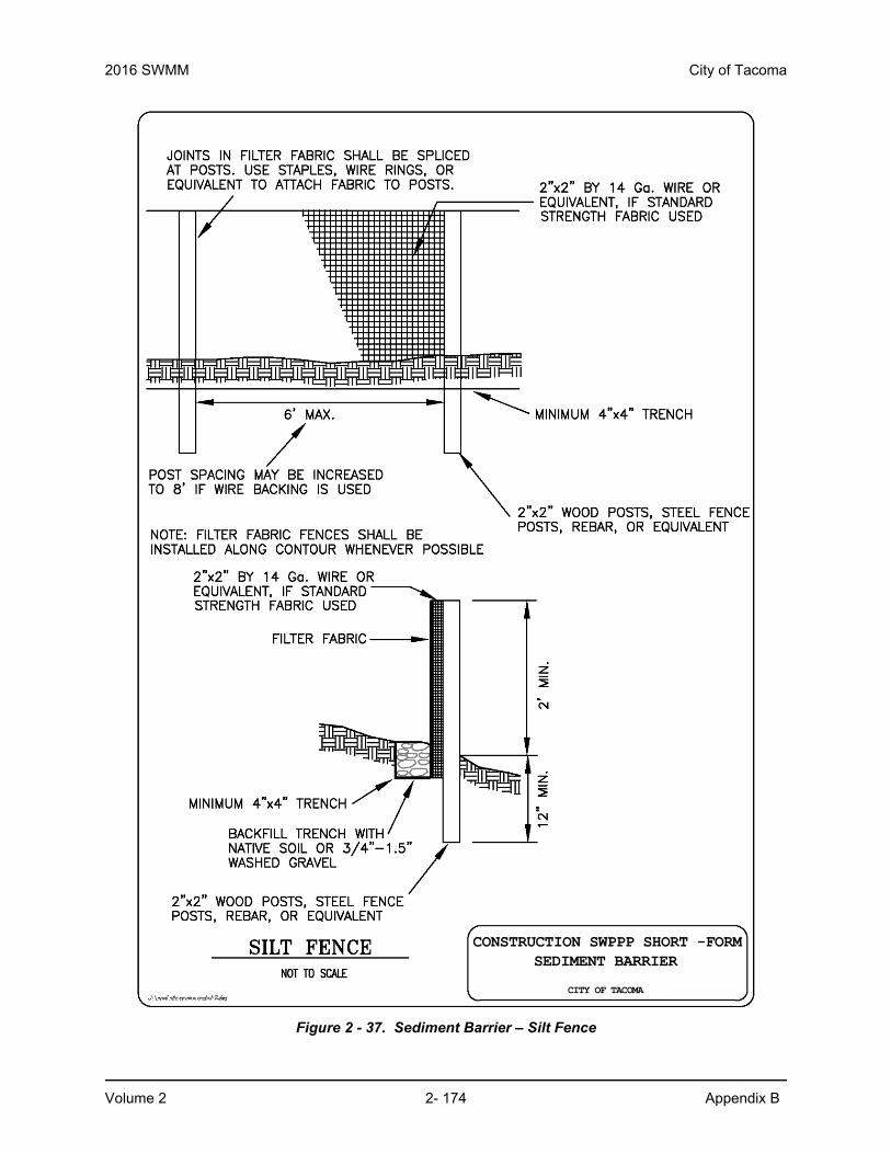
2016 SWMM City of Tacoma
Volume 2 2- 174 Appendix B
Figure 2 - 37. Sediment Barrier – Silt Fence
CONSTRUCTION SWPPP SHORT -FORMSEDIMENT BARRIER
CITY OF TACOMA

City of Tacoma 2016 SWMM
Appendix B 2- 175 Volume 2
Figure 2 - 38. Sediment (Berm) Barrier – Straw Wattle Rolls
CONSTRUCTION SWPPP SHORT -FORMSEDIMENT (BERM) BARRIER
CITY OF TACOMA
STRAW WATTLE ROLLSNOT TO SCALE

2016 SWMM City of Tacoma
Volume 2 2- 176 Appendix B
Figure 2 - 39. Catch Basin Protection – Bag Filter
CONSTRUCTION SWPPP SHORT -FORMCATCH BASIN PROTECTION
CITY OF TACOMA
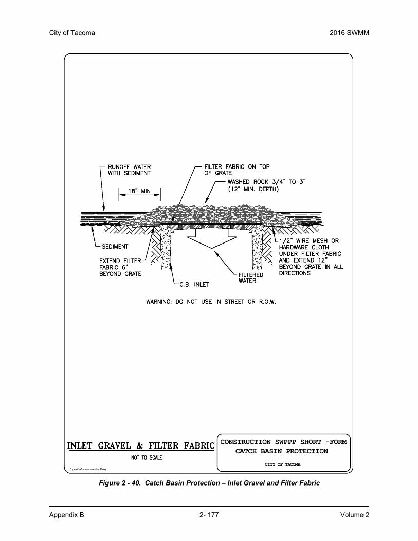
City of Tacoma 2016 SWMM
Appendix B 2- 177 Volume 2
Figure 2 - 40. Catch Basin Protection – Inlet Gravel and Filter Fabric
CONSTRUCTION SWPPP SHORT -FORMCATCH BASIN PROTECTION
CITY OF TACOMA

2016 SWMM City of Tacoma
Volume 2 2- 178 Appendix B
Figure 2 - 41. Water Runoff Containment/Control – Sediment Trap Cross-Section
CONSTRUCTION SWPPP SHORT -FORMWATER RUNOFF CONTAINMENT /CONTROL
CITY OF TACOMA

City of Tacoma 2016 SWMM
Appendix B 2- 179 Volume 2
Figure 2 - 42. Water Runoff Containment/Control – Sediment Trap Outlet
CONSTRUCTION SWPPP SHORT -FORMWATER RUNOFF CONTAINMENT /CONTROL
CITY OF TACOMA

2016 SWMM City of Tacoma
Volume 2 2- 180 Appendix B
Figure 2 - 43. Water Runoff Containment/Control – Drainage Swale Cross-Sections
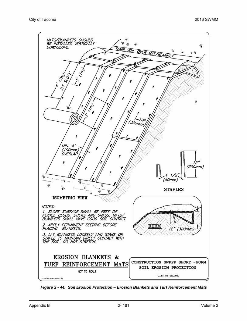
City of Tacoma 2016 SWMM
Appendix B 2- 181 Volume 2
Figure 2 - 44. Soil Erosion Protection – Erosion Blankets and Turf Reinforcement Mats
CONSTRUCTION SWPPP SHORT -FORMSOIL EROSION PROTECTION
CITY OF TACOMA

2016 SWMM City of Tacoma
Volume 2 2- 182 Appendix B
Figure 2 - 45. Soil Erosion Protection – Rip Rap Protection
CONSTRUCTION SWPPP SHORT -FORMSOIL EROSION PROTECTION
CITY OF TACOMA

City of Tacoma 2016 SWMM
Appendix B 2- 183 Volume 2
Figure 2 - 46. Soil Erosion Protection – Pipe Slope Drains
PIPE SLOPE DRAINSCONSTRUCTION SWPPP SHORT -FORM
SOIL EROSION PROTECTION
CITY OF TACOMA

2016 SWMM City of Tacoma
Volume 2 2- 184 Appendix B
This Page Intentionally Left Blank